
Modeling GMPLS and Optical MPLS Networks · Modeling GMPLS and optical M PLS networks Henrik...
8
General rights Copyright and moral rights for the publications made accessible in the public portal are retained by the authors and/or other copyright owners and it is a condition of accessing publications that users recognise and abide by the legal requirements associated with these rights. Users may download and print one copy of any publication from the public portal for the purpose of private study or research. You may not further distribute the material or use it for any profit-making activity or commercial gain You may freely distribute the URL identifying the publication in the public portal If you believe that this document breaches copyright please contact us providing details, and we will remove access to the work immediately and investigate your claim. Downloaded from orbit.dtu.dk on: May 26, 2020 Modeling GMPLS and Optical MPLS Networks Christiansen, Henrik Lehrmann; Wessing, Henrik Published in: 10th International Conference on Telecommunications, 2003. ICT 2003. Link to article, DOI: 10.1109/ICTEL.2003.1191237 Publication date: 2003 Document Version Publisher's PDF, also known as Version of record Link back to DTU Orbit Citation (APA): Christiansen, H. L., & Wessing, H. (2003). Modeling GMPLS and Optical MPLS Networks. In 10th International Conference on Telecommunications, 2003. ICT 2003. IEEE. https://doi.org/10.1109/ICTEL.2003.1191237
Transcript of Modeling GMPLS and Optical MPLS Networks · Modeling GMPLS and optical M PLS networks Henrik...

General rights Copyright and moral rights for the publications made accessible in the public portal are retained by the authors and/or other copyright owners and it is a condition of accessing publications that users recognise and abide by the legal requirements associated with these rights.
Users may download and print one copy of any publication from the public portal for the purpose of private study or research.
You may not further distribute the material or use it for any profit-making activity or commercial gain
You may freely distribute the URL identifying the publication in the public portal If you believe that this document breaches copyright please contact us providing details, and we will remove access to the work immediately and investigate your claim.
Downloaded from orbit.dtu.dk on: May 26, 2020
Modeling GMPLS and Optical MPLS Networks
Christiansen, Henrik Lehrmann; Wessing, Henrik
Published in:10th International Conference on Telecommunications, 2003. ICT 2003.
Link to article, DOI:10.1109/ICTEL.2003.1191237
Publication date:2003
Document VersionPublisher's PDF, also known as Version of record
Link back to DTU Orbit
Citation (APA):Christiansen, H. L., & Wessing, H. (2003). Modeling GMPLS and Optical MPLS Networks. In 10th InternationalConference on Telecommunications, 2003. ICT 2003. IEEE. https://doi.org/10.1109/ICTEL.2003.1191237

Modeling GMPLS and optical M PLS networks Henrik Christiansen and Henrik Wesr ing
COM Bldg. 345V. Technical University of Dent lark
2800 Kgs. Lyngby Denmark
E-mail: [email protected]
Abstract A consequence of migrating the existing Internet architecture to an all-optical one i s that the network wi l l consist o f a mixture of equipment, ranging from electrical routers to all,optical packet switches. Hence, future networks wil l consist ofmultiple do- ., mains employing different technologies: The MPLS concept is : attractive because it can work as a unifying control structure : . '
covering a l l kchnologies. This paper describes how a novel ,. : ' scheme for optical MPLS and circuit switched GMPLS based
.. '
'
~ .:. :: 'networks can incorporated in such multi-domain, MPLS-based
.. ' ing GMPLS the proposed novel scheme,is implementedand. "
scenarios and how i t could be modeled. Network-nodes support-
:.. ' : ' routing and path setup i s demonstrated. :.: . . . ' . ' . . , . . . . . . .
Introduction I n the old days, the vision was 1 0 create one single technology for multi service networks. This was one of the drivers behind developing and deplo)ing AThl. Howwer. the technologies be- ing dcveloped today are of a different nature. I t i s no longer likcly wi th a network bascd on one single technology. simply hecause the vast amount o f equipment in e.g., thc glohal Internet ir ides instant upgrtddreplaccnieiit impossible. hligration to future technologies w i l l be sccn as islands popping up and this gradual upgrade creates hcterogencous networks consisting of a number of different technologies. Currently, for instnncc. optical technologies arc being inmduccd into the networks, but clectri- caI routers/suitche~ are s t i l l prcsenl. Thus, the networks of thc future w i l l be niulti tcchnolagy, mulu service networks as sketched in Figure I. Add to that the requirements of traffic en- gineering capabilities and you will end up with 3 very coiriplex network
Figure I : A multi-domain network comprising different rechnologies
This has had an impact on the smcture of modem networks, but also this has created a requirement for special adaptation devices that are able to propagate traffic between network domains run- ning different technologies and for a common control plane
structure able to inify all these technologies and create a useful network. A closc r look at the adaptation deviceqcan be found in [Chr2001]. In this paper the emphasis i s on the control part of the network. This paper is org mized as follows. Firstly, a brief MPLS tutorial is provided. The] I the limitations fdiintroducing optical MPLS are reviewed, an I two possible approaches are presented. One is :anovel approact, which:8voids'fieadermodifica'tion; and the other is GMF'LS., The integration of th&technplogies is Waled and i t ' is describe j how to modt1'these'~combineii MPLS I ~' : GMPLS networi s. The GMPLS as well as the optical MPLS OPNET model a 'e then preSented.dong-vv'ith some simulation results that verif:'. the function&ty and,illustiatk how the models interoperates wit I the build in OPNET M P L S niodel.
. .. . . . . . . . i MPLS badd concepts This qection intri duca thc MPLS nrtworking concept suitable for electrical pac Let snitching. The use o i the MPLS concept with all-optical r 3work nodes i s considered and n novel scheme and the GMPLS :oncept is presented i ts solutions to tha faced problems.
Basic proper ies of MPLS MPLS IRos2001 11 is a neiworking concept that i s based mainly on a shift o f al l c implex functionality to the cdge of the network, lraving only r im rle operation for the core network and hence cnabling fast and efficient opcr2tion The control plane (thst takes ewe of e.g. routing) and switching (packer forwarding) are completely decol plcd, which yields the aJv~ntagcous properly that they can he i husen independently. This is the main rcason why we in this p, per can consider routing and structural issues without treating I .g.. packet forwarding explicitly. MP1.S is de- signed as a piire :verything over evcrything'concept. hence its name. In reality, iowever. i ts predominant use and the majority o f standardizatio I work arc focused on carrying IP traffic with MPLS, which i s h e to thc importance of l he ubiquitous Internet. In MPLS packet! are forwarded along routes called Label Switched Paths ( SPs) that may be determined by routing proto- cols hascd on prr lefined traffic classcs called Forward Equiva- lent Classes (FE( s). An FEC can be cquivalent to a single entry in a conventional IP routing table or i t can be an aggregation of multiple entries. i n W.C can also be specified based on a num- ber of ddditional :onsuaints such as originating address, rccciv- ing pon numher . nd QoS parameters. Thesc LSPs are defined in h e switches by U ;ing labels, which arc distributed by a Label Distnbuuon Pro1 col (LDP) responsible for mapping between routing and s u i t c ling. The MPLS standard doesn't specify one specific label dis rihution protocol; i t just highlights the required properties. Curre ttly. four protocols of which two are new and two are mdi f ica ions of existing protocols are mentioned in the standds IAnd2( Ol][Rckh2000][Jamol999j[Brad19971.
0-7803-7661-7/03/% 17.0002003 JEEE
288
Authorized licensed use limited to: Danmarks Tekniske Informationscenter. Downloaded on March 03,2010 at 09:30:20 EST from IEEE Xplore. Restrictions apply.

One ofthe major benefits of the MPLS concept is its ability U) perform traffic engineering, i.e., to be able to control how traffic tlows through the network, which i s one of the prerequisites for providing QoS guarantees on connections. Generally, traffic engineering implies to route along non-shortesl paths and util- izes Constraint Based Routing (CBR) where the routes are calcu- lated subject to performance- and administrative constraints, which are assigned by the network management system, based on e.g., traffic measurements. In MPLS. switches are generally called Label Switch Routers (LSRs). Ingress edge LSRs take care of attaching short, fixed length labels to packets when they enter the MPLS domain, which includes the non-trivial task of determining to which FEC a given packet belongs. Within the core of the network forward- ing wil l be based on thc label only, and before leaving the MPLS domain packets have their label removed by the egress edge LSR, as it.is.sketched in Figure 2. . .. . .
-- Label rwilched path
Figure 2: The label is used only within one MPLS domain. By attaching diflerent labels ar rhe ingress LSR. different roelee9 rhough rhe network for Ihe same desfinariori can be selecred, which nllowr for rrofric engi-
aeering.
The labels are generally not kept constant along an LSP and thus a path through the network i s defined by a sequence of labels, all o f which are assigned by Ihe LDP. Within the core switches only the labels are examined, and what distinguishes this method from that o f conventional IP routing are the loose coupling be- tween the label and the destination address as well as the lookup scheme within the switches themselves. The labels used by MPLS require exact match in the lookup tables, which i s a much simpler operation than LPM [Rekh1995]. I.e., OSPF would build a routing table i s each LSR and based on this information and possibly additional information the labcl distribution protocol builds another table in which the lnbel i s used as the key. The outcome of a table lookup i s information about outgoing port number and the outgoing label, which i s used to replace the label contained within the packet as well as expediting the packet to the designated output port. The label replacement operation i s usually called lnbel swrtppirrg and i s the most common packet modification operation in MPLS. In addition, when working with multiple domains in a network, the single label might he
replaced by a stack of labels with only the top label being used within one particular domain. At domain boundaries label swap- ping i s insufficient and must be exchanged for more complex operations such as label pushing and popping.
Optical MPLS MPLS was designed for packet switched networks. However, when considering all-optical devices, packet switching using header modification i s not yet a mature technology. Even though switching of optical signals potentially i s done with very high bit rates [Dan1997, Hun2000, Chi19981, the approach is facing sev- eral problems. Regeneration of the signal through 2R or 1R re- generation is required if several switches are cascaded [Wol1999] and buffering of packets and optical label swapping are two challenges that are only solved in the labs, even though .attempts have been done to reduce the buffer requirements by utiiizing the.wavelength dimension [Danl9971: . .
Key. ,. . identification ..
As previously described, header modification is a main techno- logical limitationfor introducing optical MPLS network. This problem is addressed:in the key identification scheme [WessOOI][Chr2002], where the requirements to the optical layer are reduced. The concept of the scheme i s shown in Figure. 3, for a nctwork comprising two edge nodes and three core nodes. Each node is initially assigned a unique so-called key.
Output port = func(labe1, key)
Figure 3; Concept of the k y idmriflcarion approach. The label, created at rhe edge node. is used together wtrlz a morhemorical funclion to iden- rib rhe ourputporr in eoch core MPLS node.
I t is desired to route the packet through the core nodes repre- sented with key I and key 2. This i s achieved by creating a label at the ingress node, and by using this label and the node specific keys each core node calculates the outgoing port by a function on the label and the key. The mathematical function i s based on the Chinese Remninder Theorem [Cormen]. which states that- with some restrictions- it is possible to define two independent arrays of integers of same length and combine those to a single scalar, which we wil l use as the label. Then, by a simple modulo function on the label (the scalar) and an integer from the first array, the result i s the value fmm the other array. Hence, by defining the first a m y as the keys for the nodes along the path and the second array as the desired output ports for the nodes, then the label is created and at each node the correct output port is simply calculated. The only restriction is that all the keys should he pair-wise relative primes.
289
Authorized licensed use limited to: Danmarks Tekniske Informationscenter. Downloaded on March 03,2010 at 09:30:20 EST from IEEE Xplore. Restrictions apply.

As the same label is used at all the nodes, it is not necessary to modify the header along the path. Hence, optical header modifi- cation is avoided as the label is only created and removed at the edge LSRs. The scheme differs from "normal" MPLS as the full switching information is carried within the header. This might reduce the scalability of the scheme for very large network sizes, but on the other hand the use header modification and mainte- nance of an LDP is avoided.
GMPLS GMPLS is.a generalization of MPLS that allows a seamless in- tegration of a multitude of technologies, especially circuit switched systems, with packet switched networks. Thus, inter- facing with traditional telecom TDM systems (e.g. SONET I
.,. SDH) and wavelength routed optical networks is possible.with .the.nse of GMPLS. GMPLS is in widcspread.Use and have.becn
~' iinplemented,by several manufacturers [Ber2002]. :In, contrast to optical packet switching technologies, the le nologies for optical circuit switching are far more accessible,in!. the core network. By using mixed-technology, multi domain
ages of different technologies can be com- 9
is normally that a unified control and man lacking. However, by integrating MPLS,
. :
:
.'
'. .key-MPLS and GMPLS a number of advantages are significant: The,integration is depicted in Figure 4 where the big cloud de,'.:: notes the.MPLS based domain and the smaller clouds are islands
"of key-MPLS and GhlPLS sub-domains. I > ' ,
. . ~ ~
Figure 4: GMPLS in n typical usoge seenorio where GMPLS is used (IS
'irlnnds' in [he network.
A unified control and management structure can he uscd for the full cloud. This enables support of traffic engineering even though different underlying physical layers are used. Furthermore the advantages for both circuit- and packet switched networks is combined, which is advantageous as it of- fers:
Traffic engineering capabilities, High capacity core Flexible, controllable edge Protocol independence (i.e., e.g. IP interoperability)
Hence GMFLS for circuit switched networks while allowing a management structure similar to standard MPLS.
Modeling and integration The models in It is paper have been made with OPNET modeler 8.0 and the MPL 5 model suite. The MPLS model has been ex- tended and modi ied in order to create GMPLS and key-ID net- work elements.
Modeling Gh IPLS Real GMPLS ne works are highly complex and may cover de- vices such as oplical wavelength switches and SONET network
,,nodes, i.e. GMPI .S can operate with as well electronic as optical technologies. He ice, GMPLS networks can get very complex since a multitude of technologies are hidden there, implying a vast number of F P ~ W O ~ S , devices and configuration options. The real-life net! iork must he simplified greatly.~in, order to be able,to build a m idel that can produceresults within an accept;
..able . . . timeframe.. L brute-force,model Irks to model thi 'real network i n ev
. . . . Below the,goals, or the simulation ar that the simplifie i simulation model
, i .!he model must t e simple enough to.a, hile representir g a fair model of the
'!.
:. Requircmcnts tl I the model , The goal of this : imulation study i .' GMPLS interact: with an MPLS based network..With !he model
it should be poss:ble to measurelstudy: . . . . , . Call seti:ip probability - Optical 'ignal quality
s Networl!. topology I routing issues Label l4igth (when model is used for key-MPLS)
A list of input pa'ameters is provided below: I
OPNET implem mtation The MPLS mode has been extcndedlmoditied in order to create a GMPLS netwol k element that can he built into MPLS network. This GMPLS mo lek element represents the entire GMPLS net- work, i.e. a conlp ete topology can he built with this single node. Figure 4 illustratf E how the GMPLS network can interowrate with MPLS devio domain in this in
:s, i.e., LSPs can be setup through Lhe'GMPLS :ed environment. .
290
Authorized licensed use limited to: Danmarks Tekniske Informationscenter. Downloaded on March 03,2010 at 09:30:20 EST from IEEE Xplore. Restrictions apply.

Figure 5: A GMPLSmodel, wh i .h . .Mi~ l~ro~e~a te , with MPLS, has been builf info OPNET. . I . . . . '.. .. .
. . . . . . .
. . , . ., . . . . . , . . . . . . .
More drrails of the implemented model. In order to minimize the modifications neeJed in the OPNET code, GMI'IS has hren implemented as a separate process within the network nodes. The LDP process has then just heen modified to detect whcther this GMPLS process is oresent or not (and hence whether his is a MPLS or GGPLS n&)
Figure 6: CMPLS has been implemented os 0 repororeprocess in the MPLS node model
The details of the process model is shown below (figure 6)
. . ... . . Figure 7: The'GMPLSprociss model '';
...... , . .::
Topology generation isperformed by. using the Route package in OPNET. The GMPLS implementations allows for either topol- ogy import from:a fileor.ge based on a specification size (number of nodes and links). Motlelingne has been studied by a number of researchers [ieg1996] [Fen20001 and it has heen shown that the topologieshave an impact on the network behav- ior. The topologies generated.are suited to model an optical WDM network, i.e. the capacities of each link is given as a number of wavelengths. The actual capacity (i.e., bit rate) of each wavelength is not modeled explicitly. This is not necessary when path setup is considered as in this study.
The setup state tries to find a route through the network. One path requires one available wavelength from source to destina- tion node. An attempt is made to find the shortest possible path though the network. This minimizes the overall capacity con- sumption of the oath and moreover (id the network is build from optical cross-connects) maximizes the signal quality. If the net- work possesses insufficient resources, the setup request is re- jected.
Release request causes all resources associated with a given path to be released and they thus become available for future call setup requests. Simulation results This section contains results from simulations on the GMPLS model.
Now, let's try to arbitrarily generate network topologies. The results shown below are obtained for a network consisting of 20 nodes randomly (uniformly distributed) interconnected by 40 links. In total approximately 1750 setup requests were sent to this network. The paths are then active for a random time and then tom down. Figure 8 shows the number of LSPs in the network. Paths setup is accomplished in the following way: The edge of the GMPLS domain receives the setup request from the surrounding MPLS network. Then an attempt is made to route the call though the GMPLS domain is made. To mimic all kinds of setup requests,
on of arbitrary topologies
29 1
Authorized licensed use limited to: Danmarks Tekniske Informationscenter. Downloaded on March 03,2010 at 09:30:20 EST from IEEE Xplore. Restrictions apply.
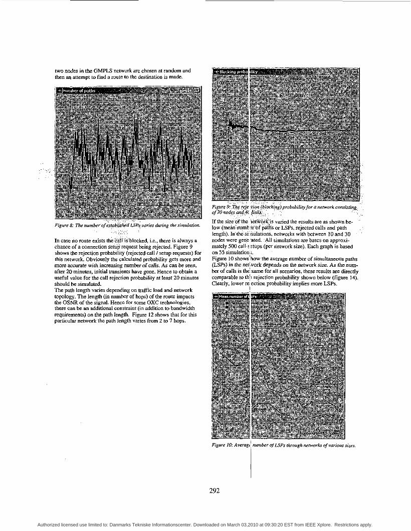
, . - . Figure 8; The number of &tqbl&d LSBs:vnrieies during the simularion.
In case no route exists the call is'blocked, i.e., there is always a chance of a connection s'e&p.request being rejected. Figure 9 shows the rejection probability (rejected call I setup requests) for this network. Obviously the calculated probability gets more and more accurate with increasing number of calls. As can be seen, after 20 minutes, initial transients have gone. Hence to obtain a useful value for the call rejection probability at least 20 minutes should be simulated. The path length varies depending on traffic load and network topology. The length (in number of hops) of the route impacts the OSNR of the signal. Hence for some OXC technologies, there can be an additional constraint (in addition to handwidth requirements) on the path length. Figure 12 shows that for this particular network the path length varies from 2 to 7 hops.
. . . . . . . .,.., , ,... .
two nodes in the GMF'LS network are chosen at random and then an attempt to find a mute to the destination is made.
.. . . . .., .:..... ~. ., . . . Figure 9rThq rej.e ?ion fbl0ckirtg)pmbabiliq for a nerwork consisting of 20 nodes a@.$( $nkr,. .... :'. : . ': . .. , If the size of the, i&two&& varied the results are as shown be- low (mear inh t zr6f pitiis or LSPs, rejected calls and path length). 1n'the:sii riulations, networks with between 10 and 30 nodes were gene sted. .All simulations are bases on approxi- mately 500 calk :tups (per network size). Each graph is based on 55 simulation,;. Figure 10 shows how the average number of simultaneous paths (UPS) in the net:.work depends on the network size. As the num- ber of calls is the same for all scenarios, these results are directly comparable to th': rejection probability shown below (figure 14). Clearly, lower re ection probability implies more LSPs.
' '
I
Figure IO: Avcragej number of U P S through network of various sires
292
Authorized licensed use limited to: Danmarks Tekniske Informationscenter. Downloaded on March 03,2010 at 09:30:20 EST from IEEE Xplore. Restrictions apply.

. . . . . ,, . . . Figure 11: Rejection (blocking) prqbability for a number of different network sires.
The GMPLS model has been iniegrated with the OPNET MPLS models. Figure 12 shows a scenario where GMPLS is used is the core of a MPLS network.
.,; . .. , . . . , . .. . . . . . ,
Figure 12: The CMPLT models are fully integrated with the OPNET MPLT models.
MPLS setup request are propagated to all involved nodes by the LDP protocol. The GMPLS model responds to these setup re- quest by setting up a path. GMPLS path setups are reported in the OPNET simulation log. Hence an end-to-end path can cross
as well MPLS and GMPLS domains in the network. In a typical scenario, where GMPLS is used in the core, the path will thus be MPLS-GMPLS/key -MPLS-MPLS.
Modeling the Key MPLS scheme The scalability of the scheme is evaluated through simulation of randomly connected networks of various sizes. The result is shown in Figure 13, where the average and the maximum values represent typical and worst-case values, re- spectively. It is shown that a label length of about 2 bytes is suf- ficient to support network sizes of up to 10 all-optical network nodes. Larger networks will generally require longer paths, which are infeasible without optical regeneration.
. .
. . , . . . . . . .. . .. . . 1
111
--cJoii*,
--tOl,i*f 1; U -d-SOiii*I
Figure 13: Required sue of labelfield for dif/eerenr network sizes
Clearly the length increases with networks size, but interestingly enough the length is appropriate for optical networks and does not severely impact the use of network resources.
i Blocking probabillty
0.45 0.4
0.-
0.25 0.3 0.2
.... ~ , . . .SO 0.1s 0. I
O M 0
0 5 m n 2 0 ~ , 5 0 numb.. 0, nod..," Ih.".,ro,l
Conclusion GMPLS is becoming more and more widely used as a control plane in optical circuit switched networks. Combining GMPLS with MPLS (which in itself can seamlessly integrate a number of packet switched technologies, regardless of protocol) yields an interesting network architecture, which is rather future proof. In this paper a model of such mixed MPLS, GMPLS network has been presented. Path setup through MPLS and GMPLS has been demonstrated and impact of network size on e.g. call rejec- tion probability has been measured. Furthermore simulation on a novel packet forwarding scheme for optical MPLS networks and
293
Authorized licensed use limited to: Danmarks Tekniske Informationscenter. Downloaded on March 03,2010 at 09:30:20 EST from IEEE Xplore. Restrictions apply.

s imu la t ion results are presented that shows the feas ib i l i t y of this scheme.
References [BerZWZ] L. Bergrr, Y. Rckhtcr. '%eneraliced MPLS Signaling - Implementn- tion Survey", Internet draft, dmfi-ietf-ccamp~ginplrrignulillksurvey-0 I .txt. May ZWZ [ChrZWI] H. Chrisriansen."Using OPNFTTo Compm and Analyze Different Traffic- Bundling Schemer", OPNETWork2001. [Corm9901 T. H. Cormen. C. E. Leiserson. R. L. Rivest. -'letmduction to Algo- rithms''. MIT Press. 1990. [BanZOOI] A. Banejee. J.Drake, J.P.Lang, BTurner. K.Kompella. and Y.Rkhier,"GeneTBliled Mu~~~~Io~ocoI Label Switching: An overview of muting and Manngeinent Enhmceinent", IEE communication magazine. January 2001 IYeq19961 E.W.Zegura. K.L.Calvert. S.Bhattncherjee"How to model an Inter- nctworl". In proceedings EEE infocoin 1996 [FenZWO] C.Ecnger. E.Limul, U. Gliese. ''Stotisfi~oI Study of the influence of Topology on Wavelength Usage in WDM networks". In proceeding of Optical Fiber Communication Conference (OFC) 2000 ~. . [RosZWIa] .F.C.. Rosen. er al. '"Multiprotocol Label Switching architecture". RFC 303.1. Jmumy 2 W I [AndZWl ] L. Andcrsson. et. al.. "LDP Specification". RFC 3036. Januilry 2001 ' [RekhZWO] Y. Rekhtcr. '"Carrying Label Information in BCP-C. Internet Draft, druft-i;tf-mpls-bgp4-mplr-04trr. work in progress. January 20W [Jam019991 6. J?rnoussi. et. al., "Constraint-Based U P Setup using LDP'. . :
Internet draft. dmfr-ielf-mpls-cr-Idp-O~.~t. work in progress, Seprembm 1999 [Bnd1997] R. B.raden. et al. "Resource ReSerVation Protocol (RSVP) -. Version '
I Func~iunal Spccificution". RFC 2205. September 1997 IRosZWlbl E.C.Roren. et al. "MPLS Label Slack Encoding", RFC 3032. Jmu- ' ' . .
. ,
. '
: ' .
.ry2001 - ' ' . . IRekh19951 Y..Rekhter. "CIDR and Clarrful Rowing", RFC 1817. Augusr 199s [Dan19971 S.L Dmielren. Mikkelsen, B., Joergenrm. C., Durhuur. l' and
SNbkjaer;.K.E:. "WDM Packet Switch Architectures and Analyrir of the Influ- ' '
ence of Tuneable Wavelemlh Converters on the Prrformance"~ Jo~lmal of ~ ~~~ " ~ ~ ~ ~ ~~~ ~~~~ ~~~~. Lightwave Technology. Vol. 15, No. 2. pp. 219-226, 1997. [Hun20001 Hunter, D.K., Andonovic. 1.. "Approaches IO Optical lntcrnet packet switching". IEEE Communications Magazine, September 2000 [Chi19981 Chiaroni, D., Lsvigne, B.. Jourdm, A.. Sotom, M.. Humon. L., et al. "Physical and logical validation of a network based on all-opticul packet switch- ing systems". Journal Of i ightwve technology. vol. 16# 12. Deccmbrr 1998 [WessWI] H. WeSsing. T. Fjeldc, H. Chririiannen, L. Dirrmann. "Novel scheme for efficient and cost-effecrive forwarding of packets in optical networks without header modification". OFC 2001,Techn. Digest, Anaheim, USA. 2001. IWo119991 Wolfson, D.. Hanren. P.B.. Kloch, A., Fje1de.T.. Jam, C.. Coquelin. A., Guillemot, 1.. Gaboit, F., Poingt, F.. Renaud. M.. "AII-o~UCPI regeneration at 40 GbiVr i n an SOA-bused Mach-Zehnder interferometer". in Technical Digest of OFC99. pmt deadline paper PD36, San Dkgo (USA), Feb.. 1999 IWesr0021 H. Wessing. H. Christiansen. T. Fjelde, L . Dirmmunn. "Novel scheme pocket forwarding wilhoul header $modifications in optical networks".Accepted for publication in IEEE JLT, August 2002. [ChrZOOZ] H.Christiansen. T.Fjclde. H.Wrssing. "Novel label process- ing schemes for MPLS", Optical Networks Magazine. Novem- bedDecember 2002
294
Authorized licensed use limited to: Danmarks Tekniske Informationscenter. Downloaded on March 03,2010 at 09:30:20 EST from IEEE Xplore. Restrictions apply.


![Photonic-GMPLS Leading Edge Code Research …biblio.yamanaka.ics.keio.ac.jp/file/67a178ae535c87ca44beb4da5c98df... · Photonic-GMPLS Leading Edge Code [INVITED PAPER] Research Consortium:](https://static.fdocuments.us/doc/165x107/5b1e55d57f8b9a116d8b6e9f/photonic-gmpls-leading-edge-code-research-photonic-gmpls-leading-edge-code-invited.jpg)