Modeling Friction and Air Effects between Cloth and...
8
Modeling Friction and Air Effects between Cloth and Deformable Bodies Zhili Chen * The Ohio State University Renguo Feng * The Ohio State University Huamin Wang * The Ohio State University (a) Cloth only (b) Inner body only (c) Our model Figure 1: Rotating sphere. We propose efficient algorithms to realistically animate friction and air effects between cloth and deformable bodies. They allow us to simulate objects that are made of a cloth layer, an inner body layer, and an air layer. Compared with cloth animation in (a) and inner body animation in (b), the animation of such objects exhibit different dynamic behaviors as shown in (c). Abstract Real-world cloth exhibits complex behaviors when it contacts de- formable bodies. In this paper, we study how to improve the simu- lation of cloth-body interactions from three perspectives: collision, friction, and air pressure. We propose an efficient and robust al- gorithm to detect the collisions between cloth and deformable bod- ies, using the surface traversal technique. We develop a friction measurement device and we use it to capture frictional data from real-world experiments. The derived friction model can realistically handle complex friction properties of cloth, including anisotropy and nonlinearity. To produce pressure effects caused by the air be- tween cloth and deformable bodies, we define an air mass field on the cloth layer and we use real-world air permeability data to ani- mate it over time. Our results demonstrate the efficiency and accu- racy of our system in simulating objects with a three-layer structure (i.e., a cloth layer, an air layer, and an inner body layer), such as pillows, comforters, down jackets, and stuffed toys. Keywords: Contacts, data-driven, material measurement, colli- sion detection, air permeability, cloth simulation. CR Categories: I.3.7 [Computer Graphics]: Three-Dimensional Graphics—Animation. Links: DL PDF * e-mail: {chenzhi, fengr, whmin}@cse.ohio-state.edu 1 Introduction In the real world, cloth is often used as a cover to protect its in- terior from separation, moisture, heat, and dust. For bedding and clothing, the interior is made of soft materials that feel comfortable and warm. Animating the cloth cover and its interior requires a simulator to solve not only cloth and deformable body dynamics, but also their interactions. While graphics researchers have made substantial progress in simulating and modeling cloth [Wang et al. 2011; Zheng and James 2012; Miguel et al. 2012] and deformable bodies [Bickel et al. 2009; Faure et al. 2011; Coros et al. 2012] re- cently, how to efficiently and accurately handle their interactions is still a less studied problem. Many cloth animation effects, such as wrinkles and folds, are formed when cloth contacts itself or other objects. Without accurately handling the contacts, we cannot faith- fully produce interesting cloth behaviors as in Figure 1. The challenges in simulating the contacts between cloth and de- formable bodies come from two main reasons. Firstly, a cloth cover frequently collides with its inner deformable body, making the col- lision detection process more computationally expensive. Such col- lisions often occur coherently in space and time, while self colli- sions of cloth are less common. We think these properties can be used to improve the efficiency of collision detection in this cloth- body interaction problem. Secondly, the contact behaviors of cloth and deformable bodies are highly complex in the real world, due to different combinations of cloth and deformable body materials. For example, their frictions can be nonlinear, anisotropic, and even asymmetric. The air trapped between cloth and deformable bod- ies provides more interesting effects in cloth animation, but it also requires more computational cost to simulate using fluid dynamics. How to model these behaviors and how to incorporate them into ex- isting simulators have not been well studied in computer graphics or textile engineering yet, as far as we know. We present a systematic study on efficiently and accurately animat- ing contact behaviors between cloth and deformable bodies. The goal of our study is to simulate real-world objects that can be mod- eled by a three-layer structure, including a cloth cover as its outer layer, a deformable body as its inner layer, and an in-between air layer. Under this representation, we develop novel techniques to model and simulate cloth-body interaction from three aspects: col- lision, friction, and air pressure. Our main contributions are:
Transcript of Modeling Friction and Air Effects between Cloth and...

Modeling Friction and Air Effects between Cloth and Deformable Bodies
Zhili Chen∗
The Ohio State UniversityRenguo Feng∗
The Ohio State UniversityHuamin Wang∗
The Ohio State University
(a) Cloth only (b) Inner body only (c) Our model
Figure 1: Rotating sphere. We propose efficient algorithms to realistically animate friction and air effects between cloth and deformablebodies. They allow us to simulate objects that are made of a cloth layer, an inner body layer, and an air layer. Compared with cloth animationin (a) and inner body animation in (b), the animation of such objects exhibit different dynamic behaviors as shown in (c).
Abstract
Real-world cloth exhibits complex behaviors when it contacts de-formable bodies. In this paper, we study how to improve the simu-lation of cloth-body interactions from three perspectives: collision,friction, and air pressure. We propose an efficient and robust al-gorithm to detect the collisions between cloth and deformable bod-ies, using the surface traversal technique. We develop a frictionmeasurement device and we use it to capture frictional data fromreal-world experiments. The derived friction model can realisticallyhandle complex friction properties of cloth, including anisotropyand nonlinearity. To produce pressure effects caused by the air be-tween cloth and deformable bodies, we define an air mass field onthe cloth layer and we use real-world air permeability data to ani-mate it over time. Our results demonstrate the efficiency and accu-racy of our system in simulating objects with a three-layer structure(i.e., a cloth layer, an air layer, and an inner body layer), such aspillows, comforters, down jackets, and stuffed toys.
Keywords: Contacts, data-driven, material measurement, colli-sion detection, air permeability, cloth simulation.
CR Categories: I.3.7 [Computer Graphics]: Three-DimensionalGraphics—Animation.
Links: DL PDF
∗e-mail: chenzhi, fengr, [email protected]
1 Introduction
In the real world, cloth is often used as a cover to protect its in-terior from separation, moisture, heat, and dust. For bedding andclothing, the interior is made of soft materials that feel comfortableand warm. Animating the cloth cover and its interior requires asimulator to solve not only cloth and deformable body dynamics,but also their interactions. While graphics researchers have madesubstantial progress in simulating and modeling cloth [Wang et al.2011; Zheng and James 2012; Miguel et al. 2012] and deformablebodies [Bickel et al. 2009; Faure et al. 2011; Coros et al. 2012] re-cently, how to efficiently and accurately handle their interactions isstill a less studied problem. Many cloth animation effects, such aswrinkles and folds, are formed when cloth contacts itself or otherobjects. Without accurately handling the contacts, we cannot faith-fully produce interesting cloth behaviors as in Figure 1.
The challenges in simulating the contacts between cloth and de-formable bodies come from two main reasons. Firstly, a cloth coverfrequently collides with its inner deformable body, making the col-lision detection process more computationally expensive. Such col-lisions often occur coherently in space and time, while self colli-sions of cloth are less common. We think these properties can beused to improve the efficiency of collision detection in this cloth-body interaction problem. Secondly, the contact behaviors of clothand deformable bodies are highly complex in the real world, dueto different combinations of cloth and deformable body materials.For example, their frictions can be nonlinear, anisotropic, and evenasymmetric. The air trapped between cloth and deformable bod-ies provides more interesting effects in cloth animation, but it alsorequires more computational cost to simulate using fluid dynamics.How to model these behaviors and how to incorporate them into ex-isting simulators have not been well studied in computer graphicsor textile engineering yet, as far as we know.
We present a systematic study on efficiently and accurately animat-ing contact behaviors between cloth and deformable bodies. Thegoal of our study is to simulate real-world objects that can be mod-eled by a three-layer structure, including a cloth cover as its outerlayer, a deformable body as its inner layer, and an in-between airlayer. Under this representation, we develop novel techniques tomodel and simulate cloth-body interaction from three aspects: col-lision, friction, and air pressure. Our main contributions are:

• A surface-traversal-based collision detection algorithm thatruns significantly faster than alternative methods. It is moreeffective in frequent contact cases, and its results are useful inhandling friction and air effects.
• A nonlinear, anisotropic friction model. We capture frictionaldata using a friction measurement device. Our dataset in-cludes multiple cloth and deformable body materials, such ascotton, leather, and sponge.
• An air mass field representing the air layer. We update thisfield by an air propagation model and an air transfer model,the latter of which animates air penetrating through cloth us-ing real-world air permeability data from [Cay et al. 2007].
The proposed models and techniques are compatible with most ex-isting cloth and deformable body simulators. We implement a sys-tem based on them and we test its performance in cloth animationexamples. Our experiment shows that this system can efficientlyand realistically handle a variety of real-world objects with a three-layer structure, such as pillows (in Figure 3), comforters (in Fig-ure 12b), and down vests (in Figure 12c).
2 Previous Work
Collision and Contact Handling. Collision handling is a largeresearch area in computer graphics and previous research has stud-ied a number of problems, including collision culling [Schvartzmanet al. 2010; Lauterbach et al. 2010; Tang et al. 2011; Zheng andJames 2012], collision detection [Provot 1997; Bridson et al. 2002;Stam 2009; Brochu et al. 2012], and asynchrony [Thomaszewskiet al. 2008; Harmon et al. 2009; Ainsley et al. 2012]. While mostprevious techniques were developed for general collision cases, ourcollision detection algorithm was specifically designed to handlecollisions between two surfaces that are in frequent contacts. Likeother discrete approaches [Baraff et al. 2003; Wicke et al. 2006],it detects and resolves collisions at the end of each time step. It isefficient and robust, when objects are not moving too fast.
A more general question is how to animate complex contactsbetween two objects. Frictions are typically modeled usingCoulomb’s law, as Bridson and colleagues [2002] showed. Pabstand collaborators [2009] proposed a friction tensor to modelanisotropic friction effects. Adhesive contacts can be modeled ei-ther by adhesive constraints [Bridson et al. 2002; Gascon et al.2010], or adhesive springs [Jimenez and Luciani 1993]. Adhesivesprings can also be used to handle the contacts between wet clothand other objects as Huber and collaborators [2011] demonstrated.Shinar and colleagues [2008] developed a unified time integrator tosimulate the contacts between deformable and solid bodies. Guen-delman and collaborators [2005] studied the contacts between clothand liquids. Lenaerts and colleagues [2008] used smoothed-particlehydrodynamics to animate fluids penetrating through porous de-formable objects. By assuming that incompressible fluid exists vir-tually between two objects, Sifakis and collaborators [2008] solvedfluid dynamics to calculate contact responses. Stam [2009] mod-elled inflation and deflation effects using uniform air pressure. Incontrast, the air pressure force in our system is derived from a time-varying air mass field, which is updated due to air transfer and prop-agation. Using it, we can conveniently handle open cloth meshesand animate wavy effects on cloth.
Material Measurement. Material measurement has been an ac-tive research topic in computer graphics in recent years. The sem-inal work of Pai and colleagues [2001] pioneered this area by cap-turing and modeling a 3D deformable object’s shape, elasticity, andfriction properties. Their idea was later extended by Lang and col-
Outer Layer
Inner Layer(Deformable Body)
Outer Layer (Cloth)
Air Layer
Figure 2: A three-layer structure. It includes an outer cloth layer,an inner deformable body layer, and an air layer. The cloth layermay or may not be closed.
laborators [2002] for more robustness, and by Schoner and col-leagues [2004] for visco-elasticity. While cloth material propertiescan also be obtained from unconstrained cloth motions as shownin [Bhat et al. 2003; Kunitomo et al. 2010], it turns out to be amuch more difficult problem due to self occlusion and large defor-mation. Instead, Wang and collaborators [2011] and Miguel andcolleagues [2012] developed their own 2D testers to measure non-linear, anisotropic elasticity behaviors of cloth. The nonlinearityalso exhibits in the elasticity of 3D objects, and Kauer and collab-orators [2002] proposed a way to measure it. Bickel and collabora-tors [2009] pushed this direction even further by considering bothnonlinearity and heterogeneity of 3D objects.
Researchers in materials science and textile engineering havealso developed a number of material measurement devices, suchas tensile testers [KATO Tech 2013b; Deben 2013], bendingtesters [KATO Tech 2013a; Taber Industries 2013], and air per-meability testers [Textest 2013; Frazier 2013; SDL Atlas 2013]. Byusing a vacuum pump to create desired pressure difference and aflowmeter to measure the amount of air passing through the testsample, most air permeability testers are designed in a Shirleytest fashion and some of their results [Cay et al. 2007] are pub-licly available online. While researchers have also designed fric-tion testers [KATO Tech 2013c; Qualitest 2013], existing frictiondatasets are still too limited for graphics research, due to variouscombinations of different materials. For this project, we are inter-ested in not only self friction properties of cloth materials, but alsothe friction properties between cloth and deformable body materi-als, such as cotton, sponge, and leather.
3 A Three-Layer Structure
Our system is based on a three-layer structure, as Figure 2 shows.The outermost layer is a cloth cover. It is represented by a trian-gle mesh and it may not be closed. We use an implicit FEM solverto simulate its planar deformation, similar to Volino and collabo-rators [2009] did. We calculate the bending forces using the hingeedge model proposed by Bridson and colleagues [2002]. Both pla-nar and bending stiffness parameters are chosen from the cloth elas-ticity database presented by Wang and collaborators [2011]. Theinnermost layer is an airtight deformable body. Since its shapeis usually smooth, we represent it by a low-resolution tetrahedralmesh and simulate it by co-rotational FEM [Muller et al. 2002].Between the cloth cover and the deformable body, we have an airlayer represented by an air mass field. In each simulation time step,we first simulate the cloth layer and the inner layer separately, andthen process their collisions (in Section 4) and frictions (in Sec-tion 5). After that, we update the air layer and apply its influenceon the cloth layer and the inner body layer (in Section 6). Figure 3shows the effects of this three-layer structure in a pillow example.
4 Collision Handling
We use the signed distances between cloth and deformable bodiesto resolve their collisions in our system. In addition, the distances
(a) Inner body only (b) Without the air layer (c) With the air layer
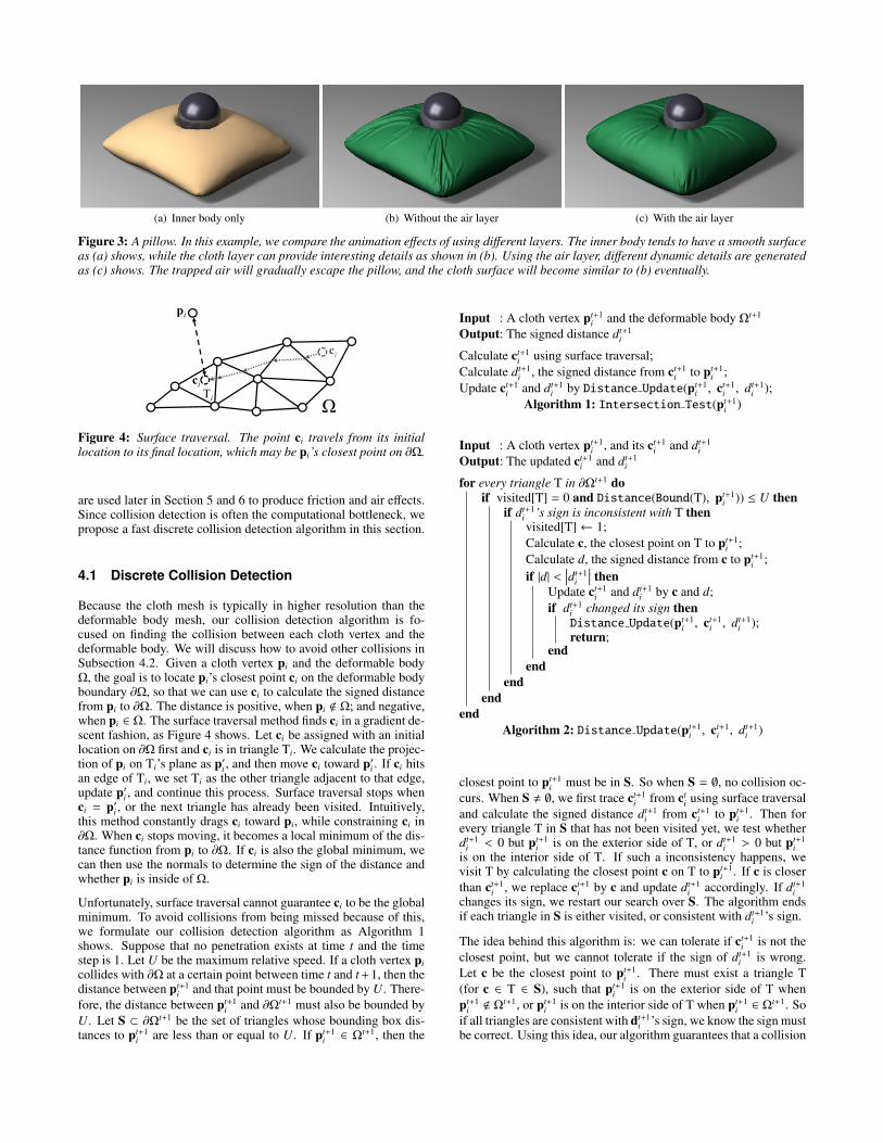
Figure 3: A pillow. In this example, we compare the animation effects of using different layers. The inner body tends to have a smooth surfaceas (a) shows, while the cloth layer can provide interesting details as shown in (b). Using the air layer, different dynamic details are generatedas (c) shows. The trapped air will gradually escape the pillow, and the cloth surface will become similar to (b) eventually.
pi
ci
ciTi ΩΩ
Figure 4: Surface traversal. The point ci travels from its initiallocation to its final location, which may be pi’s closest point on ∂Ω.
are used later in Section 5 and 6 to produce friction and air effects.Since collision detection is often the computational bottleneck, wepropose a fast discrete collision detection algorithm in this section.
4.1 Discrete Collision Detection
Because the cloth mesh is typically in higher resolution than thedeformable body mesh, our collision detection algorithm is fo-cused on finding the collision between each cloth vertex and thedeformable body. We will discuss how to avoid other collisions inSubsection 4.2. Given a cloth vertex pi and the deformable bodyΩ, the goal is to locate pi’s closest point ci on the deformable bodyboundary ∂Ω, so that we can use ci to calculate the signed distancefrom pi to ∂Ω. The distance is positive, when pi < Ω; and negative,when pi ∈ Ω. The surface traversal method finds ci in a gradient de-scent fashion, as Figure 4 shows. Let ci be assigned with an initiallocation on ∂Ω first and ci is in triangle Ti. We calculate the projec-tion of pi on Ti’s plane as p′i , and then move ci toward p′i . If ci hitsan edge of Ti, we set Ti as the other triangle adjacent to that edge,update p′i , and continue this process. Surface traversal stops whenci = p′i , or the next triangle has already been visited. Intuitively,this method constantly drags ci toward pi, while constraining ci in∂Ω. When ci stops moving, it becomes a local minimum of the dis-tance function from pi to ∂Ω. If ci is also the global minimum, wecan then use the normals to determine the sign of the distance andwhether pi is inside of Ω.
Unfortunately, surface traversal cannot guarantee ci to be the globalminimum. To avoid collisions from being missed because of this,we formulate our collision detection algorithm as Algorithm 1shows. Suppose that no penetration exists at time t and the timestep is 1. Let U be the maximum relative speed. If a cloth vertex picollides with ∂Ω at a certain point between time t and t + 1, then thedistance between pt+1
i and that point must be bounded by U. There-fore, the distance between pt+1
i and ∂Ωt+1 must also be bounded byU. Let S ⊂ ∂Ωt+1 be the set of triangles whose bounding box dis-tances to pt+1
i are less than or equal to U. If pt+1i ∈ Ωt+1, then the
Input : A cloth vertex pt+1i and the deformable body Ωt+1
Output: The signed distance dt+1i
Calculate ct+1i using surface traversal;
Calculate dt+1i , the signed distance from ct+1
i to pt+1i ;
Update ct+1i and dt+1
i by Distance Update(pt+1i , ct+1
i , dt+1i );
Algorithm 1: Intersection Test(pt+1i )
Input : A cloth vertex pt+1i , and its ct+1
i and dt+1i
Output: The updated ct+1i and dt+1
i
for every triangle T in ∂Ωt+1 doif visited[T] = 0 and Distance(Bound(T), pt+1
i )) ≤ U thenif dt+1
i ’s sign is inconsistent with T thenvisited[T]← 1;Calculate c, the closest point on T to pt+1
i ;Calculate d, the signed distance from c to pt+1
i ;if |d| <
∣∣∣dt+1i
∣∣∣ thenUpdate ct+1
i and dt+1i by c and d;
if dt+1i changed its sign thenDistance Update(pt+1
i , ct+1i , dt+1
i );return;
endend
endend
endAlgorithm 2: Distance Update(pt+1
i , ct+1i , dt+1
i )
closest point to pt+1i must be in S. So when S = ∅, no collision oc-
curs. When S , ∅, we first trace ct+1i from ct
i using surface traversaland calculate the signed distance dt+1
i from ct+1i to pt+1
i . Then forevery triangle T in S that has not been visited yet, we test whetherdt+1
i < 0 but pt+1i is on the exterior side of T, or dt+1
i > 0 but pt+1i
is on the interior side of T. If such a inconsistency happens, wevisit T by calculating the closest point c on T to pt+1
i . If c is closerthan ct+1
i , we replace ct+1i by c and update dt+1
i accordingly. If dt+1i
changes its sign, we restart our search over S. The algorithm endsif each triangle in S is either visited, or consistent with dt+1
i ’s sign.
The idea behind this algorithm is: we can tolerate if ct+1i is not the
closest point, but we cannot tolerate if the sign of dt+1i is wrong.
Let c be the closest point to pt+1i . There must exist a triangle T
(for c ∈ T ∈ S), such that pt+1i is on the exterior side of T when
pt+1i < Ωt+1, or pt+1
i is on the interior side of T when pt+1i ∈ Ωt+1. So
if all triangles are consistent with dt+1i ’s sign, we know the sign must
be correct. Using this idea, our algorithm guarantees that a collision

Figure 5: Three Pillows. Intensive collisions happen between clothand deformable bodies in this example. We use this example to testthe performance of our collision detection algorithm.
01020304050
0 2000 4000 6000 8000
Col
lisio
n C
ost (
ms)
1 2 3 40Animation Time (s)
An Exhaustive Approach
Our Approach
Figure 6: Collision detection timings per time step. Our methodruns approximately eight times faster than an exhaustive method.
must be detected if pt+1i is inside of Ωt+1. As a discrete method, it
may still miss collisions when vertices quickly travel through thebody, known as the tunneling artifact. The only solution to thisproblem under the discrete framework is to use smaller time steps,as far as we know.
Analysis. The efficiency of our algorithm comes from two rea-sons. Firstly, surface traversal explores collision coherence in spaceand time. When a cloth vertex slides over a deformable body, onlya small set of triangles need to be examined. In extreme, whenthere is no relative motion between cloth and a deformable body,only one triangle needs to be tested per cloth vertex. Secondly, thedeformable body mesh is smooth in most cases. A cloth vertexis likely to be on the exterior sides of most local triangles, if it isoutside; and it is likely to be on the interior sides of most local tri-angles, if it is inside. If so, the only additional computational cost tosurface traversal is a dot product per cloth vertex per local triangle.
Figure 6 compares the performance of our approach with the per-formance of an exhaustive approach, which calculates the vertex-triangle distance using every triangle in S. Both approaches use auniform grid acceleration structure and the comparison is based ona three pillow example containing 70K triangles as Figure 5 shows.In average, the surface traversal step in our approach visits only 1.4triangles in each time step and the whole approach runs approxi-mately eight times faster. Without using our method, our experi-ment shows that collision handling can cause more than 80 percentof the computational cost, at least half of which is spent on handlingcloth-body collisions. So the use of our method can save approxi-mately 30 to 40 percent of the overall computational cost.
Another advantage of our method is its ability to estimate the signeddistance even when a vertex is far from the inner body. Althoughthis distance may not be accurate, it is required in the air mass fieldupdate (in Section 6). For this reason, alternative approaches, suchas the edge-triangle test [Baraff et al. 2003] and the ray-intersectiontest, do not fit in our system.
4.2 Other Steps
The collision detection algorithm described in Subsection 4.1 con-siders the collisions between cloth vertices and deformable bodiesonly. But there can be other cloth-body collisions, including thecollisions between body vertices and cloth, and the collisions be-tween cloth edges and body edges. To prevent them from causingpenetration artifacts, we add a thickness buffer H = 2L/3 on thedeformable body surface, in which L is the upper bound on clothedge lengths. We typically set L from 2 to 5mm and we enforceit using the strain limiting method. By ensuring that the distancesbetween cloth vertices and the deformable body are above 2L/3,the algorithm guarantees that no other collisions can occur betweencloth and deformable bodies.
We resolve the collision between a cloth vertex and a deformablebody in the same way as Bridson and colleagues [2002] did. Specif-ically, given a distance coefficient h, if dt+1
i < H + h, we apply re-pulsion forces on the vertex and the deformable body triangle. Ifdt+1
i < H, we apply geometric constraints to prevent them fromactual collision. When there are multiple collisions, we apply theconstraints in a Jacobi fashion iteratively. Since most deformablebody surfaces are smooth, this method often converges in one ortwo iterations and we did not experience any convergence issue.But if necessary, the impact zone method can be implemented inthe future to avoid further collisions after a number of iterations.
5 Friction Effects
Real-world cloth has complex friction behaviors, including nonlin-earity and anisotropy. Here we perform an experimental study toreveal these properties and we propose a simple friction model toanimate friction effects in animation.
5.1 Friction Test
Our frictional test device is set up as Figure 7 shows. We placethe cloth sample on the test bed and we attach the deformable bodysample on the bottom of a weight cart. The friction between themhappens when a linear actuator drives a sliding piece to move. Thefriction force is measured by a Futek LSM250 load cell sensor, at-tached between the sliding piece and the weight cart. We can mod-ify the pressure forces between cloth and deformable bodies by us-ing different weights on the cart. At the beginning of each test, thesample typically experiences a large friction force due to static fric-tion. After that, the motion stabilizes and the dynamic friction forceis nearly constant.
Figure 9a compares the friction forces of different cloth materials,when they contact sponge under a 0.05kg load. Figure 9b comparesthe friction forces of different deformable bodies, when they slideover the same Jet Set cloth material under a 0.1kg load. These twoexamples demonstrate the importance of frictional tests. Withoutreal-world frictional data, we can only estimate friction coefficientsin simulation, which are often far from accurate. Figure 9c and 9dillustrate the friction behaviors of the same cloth sample, when it isplaced on the test bed with different orientations. Figure 9c showsthat the friction between sheepskin and the Jet Set material is highlyisotropic, as all of the three tests result in similar curves. Mean-while, the friction between sponge and the Jet Set material is moreanisotropic, as Figure 9d shows. To understand the nonlinearity infriction, we adjust the weight load and record the average frictionforce over time. The result in Figure 9e shows that the friction be-tween sheepskin and the Rib Knit material is more nonlinear, whilethe friction between plastic foam and the Polyester material is morelinear, largely due to its smoothness.

Weight CartLoad SensorLinear Actuator
Test Bed Sliding Piece Cloth Sample
Figure 7: The friction measurement device.
(a) Initial configuration (b) A Polyester sheet (c) A Jet Set sheet
Figure 8: Friction effects. A Polyester sheet and a Jet Set sheetexhibit different friction effects, when they both fall onto the samesponge cushion as shown in (a). The Polyester sheet slides equallyfast in the warp and weft directions as (b) shows, due to isotropicfriction. Meanwhile, the Jet Set sheet slides more toward to theright side as (c) shows, because of anisotropic friction.
Our existing dataset includes the ten cloth materials in the clothelasticity database developed by Wang and collaborators [2011] andfive deformable body materials: sponge, cotton, plastic foam, rawsheepskin, and waxed sheepskin. For each pair of materials, wefirst test the friction forces in 0, 45, and 90 directions under thesame load. If they appear to be similar, we simply assume that theirfriction is isotropic. A large number of tests are needed when thefriction force is both anisotropic and nonlinear. Fortunately, suchcases do not happen often, as our experiment shows.
5.2 Friction Model
Many existing physically based simulators use Coulomb’s lawto model the dynamic friction force between two objects: ff =−µ|fn|vt/|vt|, in which µ is a constant friction coefficient, vt is thetangent velocity, and fn is the pressure force between the two ob-jects in the normal direction. In our system, fn is obtained from thecollision impulse calculated in Subsection 4.2. Since Coulomb’slaw is only an approximation while real-world friction is more com-plex, we propose a new friction model based on the frictional datacaptured in Subsection 5.1.
We first consider the nonlinearity. Assuming that the friction be-tween two objects behaves isotropically, we can use the load-forcecurve to obtain the frictional force immediately:
ff = − f (|fn|)vt
|vt|, (1)
in which f (·) is the load-force function as in Figure 9e. The situ-ation gets complex when the friction is anisotropic, since we needto consider different load-force relationships in different directions.Here we make a few assumptions to simplify our model. Firstly,we assume that the friction is symmetric. In other words, when anobject slides in one direction, the magnitude of the received forceshould be the same as the force magnitude when the object slides inthe opposite direction. Secondly, we assume that the friction force
1N)
0 40.60.8
1
on F
orce
(N
00.20.4
0 5 10 15 20 25
TargetRib Knit
Jet SetDenim
Ti ( )
Fric
tio
Time (s)(a) Sponge test
1N)
0 40.60.8
1
on F
orce
(N
00.20.4
0 5 10 15 20 25
CottonSponge
SheepskinPlastic foam
Ti ( )
Fric
tio
Time (s)(b) Jet Set test
0 81
e (N
)
0.20.40.60.8
0° 45° 90°ictio
n Fo
rce
00 5 10 15 20 25
Time (s)
Fri
(c) Isotropic test
0 81
e (N
)
0.20.40.60.8
0° 45° 90°ictio
n Fo
rce
00 5 10 15 20 25
Time (s)
Fri
(d) Anisotropic test
2N)
1
1.5
Rib Kniton F
orce
(N0
0.5
0 1 2 3 4 5 6 7
PolyesterRib Knit
Fric
tio
Normal Force (N)Normal Force (N)(e) Nonlinearity test
1.5 Captured 30°Captured 45°(N
)
0.5
1 Captured 60°
Estimated 30°Estimated 45°ct
ion
Forc
e
00 0.5 1 1.5
Estimated 60°
Fric
Normal Force (N)(f) Model evaluation
Figure 9: Friction test results. Our experiment shows that the fric-tion force is affected by the combination of different cloth materialsin (a) and deformable body materials in (b). Even when testing thesame materials, the friction behavior can vary in different slidingdirections as (d) shows, and the relationship between the pressureforce and the friction force can be nonlinear as (e) shows. Ourfriction model approximates these behaviors as shown in (f).
is always in the opposite direction of the tangent velocity. Last butnot least, we assume that the friction is orthotropic, so the frictionforce is symmetric to two orthogonal axes. This is a reasonable as-sumption, since most deformable body materials that we tested areisotropic and most cloth materials are orthotropic. Under these as-sumptions, we propose an anisotropic nonlinear friction model as:
ff = −uT
(f00(|fn|) f01(|fn|)f01(|fn|) f11(|fn|)
)u
vt
|vt|, (2)
in which u is the normalized 2D velocity direction in the materialspace, and f00(·), f01(·), and f11(·) are three nonlinear functions de-scribing the friction anisotropy. We obtain these three functions bysolving a linear equation, using the load-force curves in differentorientations. When the deformable body is isotropic and the clothis orthotropic, we assume that the maximum and minimum frictionforces are in the warp and weft directions. So f01(·) is zero, andf00(·) and f11(·) correspond to the 0 and 90 load-force curves im-mediately. Figure 9f compares the captured load-force curves withthe estimated curves in 30, 45 and 60, using such a model. Fig-ure 8 demonstrates the effects of our friction model in animation.
The nonlinearity in friction behaviors is often due to slight com-pressibility of the material surface. We find it to be important, butit was not considered in the previous model by Pabst and collabo-rators [2009]. We also note that friction behaviors cannot be easilydetermined by the two material properties. For example, the Jet-
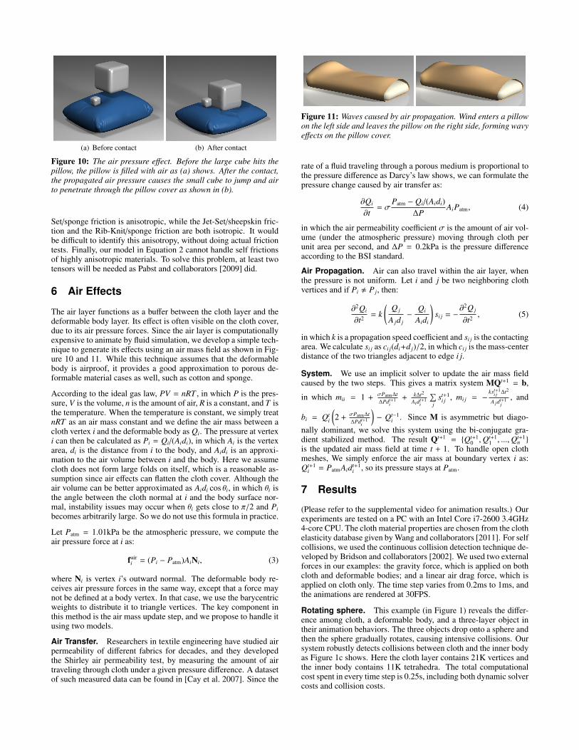
(a) Before contact (b) After contact
Figure 10: The air pressure effect. Before the large cube hits thepillow, the pillow is filled with air as (a) shows. After the contact,the propagated air pressure causes the small cube to jump and airto penetrate through the pillow cover as shown in (b).
Set/sponge friction is anisotropic, while the Jet-Set/sheepskin fric-tion and the Rib-Knit/sponge friction are both isotropic. It wouldbe difficult to identify this anisotropy, without doing actual frictiontests. Finally, our model in Equation 2 cannot handle self frictionsof highly anisotropic materials. To solve this problem, at least twotensors will be needed as Pabst and collaborators [2009] did.
6 Air Effects
The air layer functions as a buffer between the cloth layer and thedeformable body layer. Its effect is often visible on the cloth cover,due to its air pressure forces. Since the air layer is computationallyexpensive to animate by fluid simulation, we develop a simple tech-nique to generate its effects using an air mass field as shown in Fig-ure 10 and 11. While this technique assumes that the deformablebody is airproof, it provides a good approximation to porous de-formable material cases as well, such as cotton and sponge.
According to the ideal gas law, PV = nRT , in which P is the pres-sure, V is the volume, n is the amount of air, R is a constant, and T isthe temperature. When the temperature is constant, we simply treatnRT as an air mass constant and we define the air mass between acloth vertex i and the deformable body as Qi. The pressure at vertexi can then be calculated as Pi = Qi/(Aidi), in which Ai is the vertexarea, di is the distance from i to the body, and Aidi is an approxi-mation to the air volume between i and the body. Here we assumecloth does not form large folds on itself, which is a reasonable as-sumption since air effects can flatten the cloth cover. Although theair volume can be better approximated as Aidi cos θi, in which θi isthe angle between the cloth normal at i and the body surface nor-mal, instability issues may occur when θi gets close to π/2 and Pibecomes arbitrarily large. So we do not use this formula in practice.
Let Patm = 1.01kPa be the atmospheric pressure, we compute theair pressure force at i as:
fairi = (Pi − Patm)AiNi, (3)
where Ni is vertex i’s outward normal. The deformable body re-ceives air pressure forces in the same way, except that a force maynot be defined at a body vertex. In that case, we use the barycentricweights to distribute it to triangle vertices. The key component inthis method is the air mass update step, and we propose to handle itusing two models.
Air Transfer. Researchers in textile engineering have studied airpermeability of different fabrics for decades, and they developedthe Shirley air permeability test, by measuring the amount of airtraveling through cloth under a given pressure difference. A datasetof such measured data can be found in [Cay et al. 2007]. Since the
Figure 11: Waves caused by air propagation. Wind enters a pillowon the left side and leaves the pillow on the right side, forming wavyeffects on the pillow cover.
rate of a fluid traveling through a porous medium is proportional tothe pressure difference as Darcy’s law shows, we can formulate thepressure change caused by air transfer as:
∂Qi
∂t= σ
Patm − Qi/(Aidi)∆P
AiPatm, (4)
in which the air permeability coefficient σ is the amount of air vol-ume (under the atmospheric pressure) moving through cloth perunit area per second, and ∆P = 0.2kPa is the pressure differenceaccording to the BSI standard.
Air Propagation. Air can also travel within the air layer, whenthe pressure is not uniform. Let i and j be two neighboring clothvertices and if Pi , P j, then:
∂2Qi
∂t2 = k(
Q j
A jd j−
Qi
Aidi
)si j = −
∂2Q j
∂t2 , (5)
in which k is a propagation speed coefficient and si j is the contactingarea. We calculate si j as ci j(di+d j)/2, in which ci j is the mass-centerdistance of the two triangles adjacent to edge i j.
System. We use an implicit solver to update the air mass fieldcaused by the two steps. This gives a matrix system MQt+1 = b,
in which mii = 1 + σPatm∆t∆Pdt+1
i+ k∆t2
Aidt+1i
∑j
st+1i j , mi j = −
kst+1i j ∆t2
A jdt+1j
, and
bi = Qti
(2 + σPatm∆t
∆Pdt+1i
)− Qt−1
i . Since M is asymmetric but diago-
nally dominant, we solve this system using the bi-conjugate gra-dient stabilized method. The result Qt+1 = Qt+1
0 ,Qt+11 , ...,Qt+1
n
is the updated air mass field at time t + 1. To handle open clothmeshes, We simply enforce the air mass at boundary vertex i as:Qt+1
i = PatmAidt+1i , so its pressure stays at Patm.
7 Results
(Please refer to the supplemental video for animation results.) Ourexperiments are tested on a PC with an Intel Core i7-2600 3.4GHz4-core CPU. The cloth material properties are chosen from the clothelasticity database given by Wang and collaborators [2011]. For selfcollisions, we used the continuous collision detection technique de-veloped by Bridson and collaborators [2002]. We used two externalforces in our examples: the gravity force, which is applied on bothcloth and deformable bodies; and a linear air drag force, which isapplied on cloth only. The time step varies from 0.2ms to 1ms, andthe animations are rendered at 30FPS.
Rotating sphere. This example (in Figure 1) reveals the differ-ence among cloth, a deformable body, and a three-layer object intheir animation behaviors. The three objects drop onto a sphere andthen the sphere gradually rotates, causing intensive collisions. Oursystem robustly detects collisions between cloth and the inner bodyas Figure 1c shows. Here the cloth layer contains 21K vertices andthe inner body contains 11K tetrahedra. The total computationalcost spent in every time step is 0.25s, including both dynamic solvercosts and collision costs.
(a) Cloth cover (b) Bedding set (c) Down vest
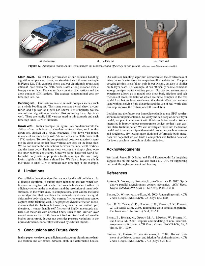
Figure 12: Animation examples that demonstrate the robustness and efficiency of our system. (The car model c©Alexander Lashko)
Cloth cover. To test the performance of our collision handlingalgorithm in open cloth cases, we simulate the cloth cover examplein Figure 12a. This example shows that our algorithm is robust andefficient, even when the cloth cover slides a long distance over abumpy car surface. The car surface contains 18K vertices and thecloth contains 80K vertices. The average computational cost pertime step is 0.05s.
Bedding set. Our system can also animate complex scenes, suchas a whole bedding set. This scene contains a cloth sheet, a com-forter, and a pillow, as Figure 12b shows. For simplicity, we useour collision algorithm to handle collisions among these objects aswell. There are totally 81K vertices used in this example and eachtime step takes 0.07s to simulate.
Down vest. In this example (in Figure 12c), we demonstrate theability of our techniques to simulate winter clothes, such as thisdown vest dressed on a virtual character. This down vest modelis made of an inner body with 5K vertices and a cloth cover with117K vertices. To save the computational cost, we adaptively sam-ple the cloth cover so that fewer vertices are used on the inner side.We do not handle the interactions between the inner cloth verticesand the inner body. The inner cloth vertices are simply glued ontothe inner body by constraints. Since we do not have real-world de-formable body material properties for this example, the inner bodylooks slightly stiffer than it should be. We plan to improve this inthe future. It takes 0.37s to simulate each time step in this example.
8 Limitations
Our collision detection algorithm cannot handle self collisions. Asa discrete algorithm, it suffers from tunneling artifacts when ver-tices are moving too fast or when deformable bodies are too thin. Itsefficiency relies on the smoothness and the resolution of inner bodysurfaces. In the worst case, its computational cost will be the sameas an algorithm that calculates the vertex-body distance using alldeformable body triangles. Our current friction experiment cannotcapture static frictions well. The proposed dynamic friction modelassumes that the friction behavior is symmetric and orthotropic,therefore, it cannot handle self frictions of highly anisotropic ma-terials or materials with oriented fibers, such as fur. Our air layermodel assumes that cloth does not fold on itself and deformablebodies are airproof. It does not consider pressure variations in thenormal direction, nor air flows blocked by external objects.
9 Conclusions and Future Work
In this paper, we developed efficient and accurate algorithms to han-dle friction and air effects between cloth and deformable bodies.
Our collision handling algorithm demonstrated the effectiveness ofusing the surface traversal technique in collision detection. The pro-posed algorithm is useful not only in our system, but also in similarmulti-layer cases. For example, it can efficiently handle collisionsamong multiple winter clothing pieces. Our friction measurementexperiment allows us to model both cloth-body frictions and selffrictions of cloth, the latter of which are more complex in the realworld. Last but not least, we showed that the air effect can be simu-lated without solving fluid dynamics and the use of real-world datacan help improve the realism of cloth simulation.
Looking into the future, our immediate plan is to use GPU acceler-ation in our implementation. To verify the accuracy of our air layermodel, we plan to compare it with fluid simulation results. We areinterested in improving our measurement device, so that it can cap-ture static frictions better. We will investigate more into the frictionmodel and its relationship with material properties, such as wetnessand roughness. By testing more cloth and deformable body mate-rials, we hope that we can build a comprehensive friction databasefor future graphics research in cloth simulation.
Acknowledgments
We thank James F. O’Brien and Ravi Ramamoothi for inspiringsuggestions on this work. We also thank NVIDIA for supportingour work through equipment and funding.
References
Ainsley, S., Vouga, E., Grinspun, E., and Tamstorf, R. 2012. Spec-ulative parallel asynchronous contact mechanics. ACM Trans.Graph. (SIGGRAPH Asia) 31, 6 (Nov.), 151:1–151:8.
Baraff, D., Witkin, A., and Kass, M. 2003. Untangling cloth. ACMTrans. Graph. (SIGGRAPH) 22 (July), 862–870.
Bhat, K. S., Twigg, C. D., Hodgins, J. K., Khosla, P. K., Popovic,Z., and Seitz, S. M. 2003. Estimating cloth simulation parame-ters from video. In Proc. of SCA, 37–51.
Bickel, B., Bacher, M., Otaduy, M. A., Matusik, W., Pfister, H.,and Gross, M. 2009. Capture and modeling of non-linear het-erogeneous soft tissue. ACM Trans. Graph. (SIGGRAPH) 28, 3(July), 89:1–89:9.
Bridson, R., Fedkiw, R., and Anderson, J. 2002. Robust treat-ment of collisions, contact and friction for cloth animation. ACMTrans. Graph. (SIGGRAPH) 21, 3 (July), 594–603.

Brochu, T., Edwards, E., and Bridson, R. 2012. Efficient geomet-rically exact continuous collision detection. ACM Trans. Graph.(SIGGRAPH) 31, 4 (July), 96:1–96:7.
Cay, A., Vassiliadis, S., Rangoussi, M., and Tarakcioglu, I. 2007.Prediction of the air permeability of woven fabrics using neuralnetworks. International Journal of Clothing Science and Tech-nology 19, 18–35.
Coros, S., Martin, S., Thomaszewski, B., Schumacher, C., Sumner,R., and Gross, M. 2012. Deformable objects alive! ACM Trans.Graph. (SIGGRAPH) 31, 4 (July), 69:1–69:9.
Deben, 2013. Biaxial tensile stage for textiles and polymers, Jan-uary. http://www.deben.co.uk/details.php?id=11.
Faure, F., Gilles, B., Bousquet, G., and Pai, D. K. 2011. Sparsemeshless models of complex deformable solids. ACM Trans.Graph. (SIGGRAPH) 30, 4 (July), 73:1–73:10.
Frazier, 2013. Differential pressure air permeability tester, Jan-uary. http://www.frazierinstrument.com/products/fap/fap.html.
Gascon, J., Zurdo, J. S., and Otaduy, M. A. 2010. Constraint-basedsimulation of adhesive contact. In Proc. of SCA, 39–44.
Guendelman, E., Selle, A., Losasso, F., and Fedkiw, R. 2005. Cou-pling water and smoke to thin deformable and rigid shells. ACMTrans. Graph. (SIGGRAPH) 24, 3 (July), 973–981.
Harmon, D., Vouga, E., Smith, B., Tamstorf, R., and Grinspun, E.2009. Asynchronous contact mechanics. ACM Trans. Graph.(SIGGRAPH) 28, 3 (July), 87:1–87:12.
Huber, M., Pabst, S., and Straßer, W. 2011. Wet cloth simulation.In ACM SIGGRAPH 2011 Posters, 10:1–10:1.
Jimenez, S., and Luciani, A. 1993. Animation of interacting ob-jects with collisions and prolonged contacts. In Proc. of the IFIPWorking Group 5.10, 129–141.
KATO Tech, 2013. KES-FB2-AUTO-A bending tester, January.http://english.keskato.co.jp/products/kes fb2.html.
KATO Tech, 2013. KES-G2 strip biaxial tensile tester, January.http://english.keskato.co.jp/products/kes g2.html.
KATO Tech, 2013. KES-SE friction tester, January.http://english.keskato.co.jp/products/kes se.html.
Kauer, M., Vuskovic, V., Dual, J., Szekely, G., and Bajka, M.2002. Inverse finite element characterization of soft tissues.Medical Image Analysis 6, 3, 257–287.
Kunitomo, S., Nakamura, S., and Morishima, S. 2010. Optimiza-tion of cloth simulation parameters by considering static and dy-namic features. In ACM SIGGRAPH 2010 Posters, 15:1–15:1.
Lang, J., Pai, D., and Woodham, R. J. 2002. Acquisition of elas-tic models for interactive simulation. International Journal ofRobotics Research 21, 8, 713–733.
Lauterbach, C., Mo, Q., and Manocha, D. 2010. gProximity:Hierarchical GPU-based operations for collision and distancequeries. In Proc. of Eurographics, vol. 29, 419–428.
Lenaerts, T., Adams, B., and Dutre, P. 2008. Porous flowin particle-based fluid simulations. ACM Trans. Graph. (SIG-GRAPH) 27, 3 (Aug.), 49:1–49:8.
Miguel, E., Bradley, D., Thomaszewski, B., Bickel, B., Matusik,W., Otaduy, M. A., and Marschner, S. 2012. Data-driven es-timation of cloth simulation models. In Proc. of Eurographics,vol. 31.
Muller, M., Dorsey, J., McMillan, L., Jagnow, R., and Cutler, B.2002. Stable real-time deformations. In Proc. of SCA, 49–54.
Pabst, S., Thomaszewski, B., and Straßer, W. 2009. Anisotropicfriction for deformable surfaces and solids. In Proc. of SCA,149–154.
Pai, D. K., Doel, K. v. d., James, D. L., Lang, J., Lloyd, J. E., Rich-mond, J. L., and Yau, S. H. 2001. Scanning physical interactionbehavior of 3D objects. In Proc. of SIGGRAPH 98, Annual Con-ference Series, 87–96.
Provot, X. 1997. Collision and self-collision handling in clothmodel dedicated to design garments. In Computer Animationand Simulation, 177–189.
Qualitest, 2013. Coefficient of friction (COF) tester, January.http://www.worldoftest.com/cof.htm.
Schoner, J. L., Lang, J., and Seidel, H.-P. 2004. Measurement-based interactive simulation of viscoelastic solids. In Proc. ofEurographics, vol. 23, 547C–556.
Schvartzman, S. C., Perez, A. G., and Otaduy, M. A. 2010. Star-contours for efficient hierarchical self-collision detection. ACMTrans. Graph. (SIGGRAPH) 29 (July), 80:1–80:8.
SDL Atlas, 2013. Air permeability tester, January.http://www.sdlatlas.com/consumable/58/.
Shinar, T., Schroeder, C., and Fedkiw, R. 2008. Two-way couplingof rigid and deformable bodies. In Proc. of SCA, 95–103.
Sifakis, E., Marino, S., and Teran, J. 2008. Globally coupledcollision handling using volume preserving impulses. In Proc.of SCA, 147–153.
Stam, J. 2009. Nucleus: Towards a unified dynamics solver forcomputer graphics. In 11th IEEE International Conference onComputer-Aided Design and Computer Graphics.
Taber Industries, 2013. Fabric stiffness tester, January.http://www.taberindustries.com/fabric-stiffness.
Tang, M., Manocha, D., Yoon, S.-E., Du, P., Heo, J.-P., and Tong,R.-F. 2011. VolCCD: Fast continuous collision culling betweendeforming volume meshes. ACM Trans. Graph. 30, 5 (Oct.),111:1–111:15.
Textest, 2013. Air Permeability Tester FX 3300 LabAir IV, Jan-uary. http://www.textest.ch/pages en/3300-IV en.htm.
Thomaszewski, B., Pabst, S., and Straßer, W. 2008. Asynchronouscloth simulation. In Proc. of Computer Graphics International.
Volino, P., Magnenat-Thalmann, N., and Faure, F. 2009. A simpleapproach to nonlinear tensile stiffness for accurate cloth simula-tion. ACM Trans. Graph. 28, 4 (September), 105:1–105:16.
Wang, H., O’Brien, J. F., and Ramamoorthi, R. 2011. Data-drivenelastic models for cloth: Modeling and measurement. ACMTrans. Graph. (SIGGRAPH) 30, 4 (July), 71:1–71:12.
Wicke, M., Lanker, H., and Gross, M. 2006. Untangling clothwith boundaries. In Proc. of Vision, Modeling, and Visualization,349–356.
Zheng, C., and James, D. L. 2012. Energy-based self-collisionculling for arbitrary mesh deformations. ACM Trans. Graph.(SIGGRAPH) 31, 4 (July), 98:1–98:12.