
Modeling and simulation of circuit-electromagnetic effects ... · Modeling and simulation of...
6
Modeling and simulation of circuit-electromagnetic effects in electronic design flow Pavel V. Nikitin 1 , Vikram Jandhyala 1 , Daniel White 2 , Nathan Champagne 2 , John D. Rockway 2 , C.-J. Richard Shi 1 , Chuanyi Yang 1 , Yong Wang 1 , Gong Ouyang 1 , Rob Sharpe 2 , and John W. Rockway 3 1 Universityof Washington, Department of Electrical Engineering, Seattle, WA 98195 Email: {nikitin, jandhyala, cjshi, cyang1, oyg, yongw}@ee.washington.edu 2 Lawrence Livermore National Laboratory, 7000 East Ave, Livermore, CA 94550 Email: {dwhite, champagne, rockway2, rsharpe} @llnl.gov 3 Space and Naval Warfare Systems Command, 4301 Pacific Highway San Diego, CA 92110 Email: [email protected] Abstract The goal of this paper is to describe a methodology for modeling and simulation of circuit-electromagnetic (EM) effects that fits into a current electronic design flow. Our methodology is based on using time-domain macromodels implemented in a hardware description language (HDL). Simulation of the entire coupled circuit-EM system can be carried out either entirely in HDL simulator or in SPICE- type circuit simulator (using model compiler for macro- model import). We also describe in detail a circuit-EM con- tact interface and a neutral mesh format necessary to allow for flexibility in choice of EM simulators. At each step of our methodology, we provide an overview of current prob- lems and solutions with reference to existing publications. As a demonstration example, we consider a simple cou- pled system (MEMS resonator connected to a lumped cir- cuit) and show that simulations using VHDL-AMS macro- model match full-wave EM results but easily fit in the de- sign flow and take significantly less time. Our methodology is straightforward and permits the use of various EM simu- lators and macromodel identification algorithms 1 . 1 This research was supported by DARPA NeoCAD Program 1. Introduction Electromagnetic effects have always been impor- tant in microwave circuits but now they have become an increasingly significant factor that affects the per- formance of modern integrated circuit (IC) systems, especially at multi-gigahertz frequencies [18]. Such sys- tems include very large scale integrated (VLSI) chips as well systems-on-chips (SoC), and the examples of ob- jects exhibiting EM behavior are interconnects, spiral inductors, traces, etc. This leads to a necessity of using ac- curate computer-automated design (CAD) tools for EM modeling and efficient use of those models in circuit simu- lation [6]. A variety of numerical electromagnetic field solving tools have been developed in the past, all of which have different limitations, capabilities, input and output formats, and computational costs. Choosing the best tool for a partic- ular task and successfully employing and integrating it into an IC CAD design flow are challenging tasks. Both circuit and EM simulations can be carried out ei- ther in time domain or frequency domain but mixed-signal circuit simulations are mostly performed in time domain (due to nonlinearity of analog circuits and sharp rise and fall times of digital signals) whereas EM simulations are mostly performed in frequency domain (due to well devel- oped frequency domain EM methods). There are three main approaches to incorporate EM sim- ulation results in SPICE-type time-domain circuit simula- tors. First approach is to extract an equivalent RLC cir- 0-7695-2093-6/04 $20.00 2004 IEEE
-
Upload
trinhkhanh -
Category
Documents
-
view
225 -
download
0
Transcript of Modeling and simulation of circuit-electromagnetic effects ... · Modeling and simulation of...
Modeling and simulation of circuit-electromagnetic effectsin electronic design flow
Pavel V. Nikitin1, Vikram Jandhyala1, Daniel White2, Nathan Champagne2, John D. Rockway2,C.-J. Richard Shi1, Chuanyi Yang1, Yong Wang1, Gong Ouyang1,
Rob Sharpe2, and John W. Rockway3
1University of Washington, Department of Electrical Engineering, Seattle, WA 98195Email: {nikitin, jandhyala, cjshi, cyang1, oyg, yongw}@ee.washington.edu
2Lawrence Livermore National Laboratory, 7000 East Ave, Livermore, CA 94550Email: {dwhite, champagne, rockway2, rsharpe} @llnl.gov
3Space and Naval Warfare Systems Command, 4301 Pacific Highway San Diego, CA 92110Email: [email protected]
Abstract
The goal of this paper is to describe a methodology formodeling and simulation of circuit-electromagnetic (EM)effects that fits into a current electronic design flow. Ourmethodology is based on using time-domain macromodelsimplemented in a hardware description language (HDL).Simulation of the entire coupled circuit-EM system can becarried out either entirely in HDL simulator or in SPICE-type circuit simulator (using model compiler for macro-model import). We also describe in detail a circuit-EM con-tact interface and a neutral mesh format necessary to allowfor flexibility in choice of EM simulators. At each step ofour methodology, we provide an overview of current prob-lems and solutions with reference to existing publications.
As a demonstration example, we consider a simple cou-pled system (MEMS resonator connected to a lumped cir-cuit) and show that simulations using VHDL-AMS macro-model match full-wave EM results but easily fit in the de-sign flow and take significantly less time. Our methodologyis straightforward and permits the use of various EM simu-lators and macromodel identification algorithms1.
1 This research was supported by DARPA NeoCAD Program
1. Introduction
Electromagnetic effects have always been impor-tant in microwave circuits but now they have becomean increasingly significant factor that affects the per-formance of modern integrated circuit (IC) systems,especially at multi-gigahertz frequencies [18]. Such sys-tems include very large scale integrated (VLSI) chips aswell systems-on-chips (SoC), and the examples of ob-jects exhibiting EM behavior are interconnects, spiralinductors, traces, etc. This leads to a necessity of using ac-curate computer-automated design (CAD) tools for EMmodeling and efficient use of those models in circuit simu-lation [6].
A variety of numerical electromagnetic field solvingtools have been developed in the past, all of which havedifferent limitations, capabilities, input and output formats,and computational costs. Choosing the best tool for a partic-ular task and successfully employing and integrating it intoan IC CAD design flow are challenging tasks.
Both circuit and EM simulations can be carried out ei-ther in time domain or frequency domain but mixed-signalcircuit simulations are mostly performed in time domain(due to nonlinearity of analog circuits and sharp rise andfall times of digital signals) whereas EM simulations aremostly performed in frequency domain (due to well devel-oped frequency domain EM methods).
There are three main approaches to incorporate EM sim-ulation results in SPICE-type time-domain circuit simula-tors. First approach is to extract an equivalent RLC cir-
0-7695-2093-6/04 $20.00 2004 IEEE

cuit [1], which can be very large (i.e. for substrate cou-pling) and cumbersome to deal with (model order reductionis often needed). Second approach is to concurrently cou-ple a circuit and EM simulator. While adding lumped pas-sives to a full-wave EM simulation is straightforward, cou-pling a full-wave EM solver with a non-linear circuit solveris not a routine procedure (e.g. FDTD-SPICE coupling hasbeen done but on case-by-case basis [15]). Third approach,which we describe in this paper, is to develop compact lin-ear EM macromodels [10].
The last approach is very convenient because macro-models can be implemented in high-level hardware descrip-tion languages used for design (such as VHDL-AMS [3]or Verilog-A [12]), easily interfaced to non-linear circuits,and re-used. Macromodeling permits significant speed-upof simulations and thus gains more and more attention inCAD community (e.g., for MEMS [17]). We should notethat propositions to extend HDL’s to directly support PDE’sand hence EM modeling have also appeared in the litera-ture [13] but this work is still in the research stage.
In this paper, we describe a methodology for modelingand simulation of circuit-EM effects on system performanceby using compact linear EM macromodels implementedin a hardware description language. We provide an exam-ple – a simple circuit-driven MEMS system analyzed usingVHDL-AMS macromodel extracted from time-domain EMsimulation. We also describe specifics of circuit-EM contactinterface and EM mesh format in a way that can be used bydifferent circuit and EM simulators.
2. Methodology
Modern electronic design flow includes such steps asschematic capture and simulation, system layout, parasiticextraction, post-layout simulation, etc. At each stage, dif-ferent tools and file formats, standard and proprietary, areused [9].
Analog and digital circuitry is typically described usingSPICE- or VHDL-type netlists, which specify how lumpedcomponents or digital logic blocks are connected together.Layout is typically described using CIF or GDS II formatfiles. These files contain 2D data about structures locatedat different chip layers and together with technology files(which contain information about thickness, material prop-erties, and stacking of different layers) give a complete 3Ddescription of a chip.
Having an ability to do an accurate post-layout simu-lation is critical for verification of functionality and per-formance of the complete system. Fully coupled circuit-electromagnetic simulations are very computationally in-tensive and are not commonly used. A typical approachused in the design process today is to perform parasitic ex-
traction and include equivalent RLC circuits into a circuitsimulator.
The process of RLC extraction from EM simulations isdifficult, but works well in many cases, especially for capac-itances of interconnects. Complex coupled problems resultin large RLC networks and require a subsequent applicationof model order reduction methods, which are not well inte-grated into design flow. Thus there is a clear need for newapproaches in coupled circuit-EM simulation.
Figure 1. Methodology.
The methodology that we propose is illustrated in Fig-ure 1. An IC system of interest contains lumped circuitsconnected at certain contact points to geometrical structuresthat exhibit EM behavior and need to be meshed and accu-rately modeled. Volumetric or surface mesh is stored in neu-tral mesh format reusable by various electromagnetic sim-ulators. From frequency- or time-domain simulation data(depending on application and frequency range of inter-
0-7695-2093-6/04 $20.00 2004 IEEE

est), time-domain macromodel can be identified and ex-tracted [20]. Such model can easily be implemented in ahardware description language (such as VHDL-AMS) andused either in HDL simulation of the whole system (circuitnetlist needs to be converted from SPICE to HDL format)or, with recent advances in model compilers [7, 23], com-piled for direct use in a SPICE-type circuit simulator.
2.1. EM simulation, contact interface,mesh format
In circuit simulation, the most popular method is node-based modified nodal analysis (MNA) [16]. In electromag-netic simulation, the variety of methods is richer and in-cludes differential methods (FDTD – finite difference timedomain, FEM – finite element method, etc.), integral equa-tion methods (MoM – method of moments, BEM – bound-ary element method, etc.), hybrid methods [21], etc. Manyof these methods can be utilized both in frequency or timedomain but traditionally only FDTD has been used for time-domain modeling, and FEM and MoM have been usedin frequency domain. Recently, new time-domain methods(TD-FEM [24], TD-MoM [26]) have been developed andsuccessfully applied to a variety of problems. An excellentsurvey of existing EM methods can be found in [11].
Each method listed above has many variations and de-serves a separate overview but most EM commercialtools are based on three major methods and their flavors– method of moments (e.g., Sonnet by Sonnet Technolo-gies), finite element method (e.g., HFSS by Ansoft Cor-poration), and finite-difference time domain method (e.g.,XFDTD by Remcom, Inc.). All electromagnetic solvers re-quire creation of some sort of grid or mesh: either vol-umetric one that includes all problem space (FEM andFDTD) or surface mesh that covers only certain sur-faces (MoM).
An electromagnetic solver applied to coupled circuit-EMproblem must recognize the existence of ports or terminalsthat connect circuit and EM subsystems and through whichthe interaction happens [22]. Exact definition is different fordifferent EM solving techniques [2]. Examples of specify-ing such interaction for FDTD can be found in [15] andfor MoM in [26, 5]. Circuit world understands currents andvoltages, and thus latter serve as common shared quantitiesat the points of circuit-EM interaction.
Assume that we have identified EM objects and lumpedcircuit elements connected to them (identification of ICpackage parts that must be modeled as EM objects is a sep-arate challenging problems that we do not address here).Then circuit-EM contact interface can be defined as an areaof the EM object surface to which a circuit element is at-tached. This concept is shown in Figure 2 (two contacts mayform a microwave port).
Figure 2. Circuit-EM contact interface.
The contact interface area can be specified in two ways:mesh-dependent and mesh-independent. Mesh-dependentmethod can be defined as specifying mesh elements that be-long to the contact interface. Mesh-independent method canbe defined as specifying 3D coordinates of contact points(using either x, y, z coordinates in the integrated chip ref-erence frame or text labels in layout/technology files). Af-ter the mesh is created, mesh faces in the vicinity of thatpoint (e.g, a spherical region of a certain radius) are recog-nized as part of contact interface.
Both ways described above have advantages and disad-vantages. Mesh-dependent method is less portable as it re-quires the existence of prior mesh but is better for accu-rate coupled simulations. Mesh-independent method doesnot require prior mesh existence and has better portabilitybut may suffer from potential problems related to mesh re-finement in the process of EM solution.
Figure 3. Mesh format.
Mesh itself can also be stored in a variety of ways. Cur-rently, many different mesh formats for EM simulation ex-ist. Unfortunately, there is no standard analogous to netliststandard for circuits. We propose to use the following neu-tral mesh format, simple and intuitive. To completely definea mesh, three files are needed: node file, element file, andmaterial file. The format of those files can be illustrated withthe example shown in Figure 3, where a surface of a per-fectly conducting object positioned in free-space is meshed
0-7695-2093-6/04 $20.00 2004 IEEE

with triangles.Node file lists coordinates of all nodes (in units selected
by user) in the cartesian coordinate system. The node filefor the example shown in Figure 3 is:
Node x y z1 x1 y1 z12 x2 y2 z2...
Element file lists all surface and volume elements (trian-gles, tetrahedra, etc.) formed by nodes which serve as ele-ment vertices. If an element belongs to a surface dividingtwo regions with different properties, those regions must bespecified by their numbers. In the example shown in Fig-ure 3 the elements are triangles on the surface dividing re-gion 1 and region 2, and the node file is:
Element n1 n2 n3 region1 region21 5 6 9 1 22 6 9 10 1 2...
Material file lists all regions (by number), their type (vol-ume, surface, layer), and their properties (permittivity, per-meability, and conductivity). Infinite conductivity for per-fect electric conductors can be denoted as PEC. The exam-ple shown in Figure 3 contains free-space (region 1) and aPEC object (region 2). The material file for this example is:
Region eps mu sigma type1 1 1 0 volume2 1 1 PEC volume...
The mesh format, described above, can be used for dif-ferent EM simulators and translated into mesh formats un-derstood by any of the commercial tools. Once an EM sim-ulation of the multi-port structure is completed, a macro-model needs to be extracted. This process is described inthe next subsection.
2.2. Macromodeling
Macromodeling is extremely important for speed-ing up simulations of complex systems, such as coupledcircuit-electromagnetic systems. In order to be easily im-plementable in a hardware description language, a macro-model must be casted into a time-domain differentialequation form. Such model can be obtained from ei-ther frequency- or time-domain EM simulation.
A number of different algorithms for extracting macro-models and reduced order models from data are avail-able [14, 8]. An advantage of using time-domain datais that in most cases passivity and stability of obtainedmacromodel are easier to guarantee than when work-ing with frequency-domain data. Thus, for illustration of
our methodology, we choose an approach where a lin-ear compact macromodel is identified from a time-domainelectromagnetic response as described in [25].
All possible information about system dynamics is the-oretically contained in an impulse response – a system re-sponse to a delta-function excitation. System response toany input can be found as a convolution of the impulse re-sponse with the input signal. This process is very compu-tationally expensive, especially for highly-resonant deviceswith long impulse responses. In addition, delta-functioncauses numerical problems in time-domain EM solvers, andmore commonly used excitation is Gaussian pulse:
u(t) = uo e−
(t−τ)2
2T2 (1)
with -3dB bandwidth of 0.13/T.System response to a Gaussian pulse can allow one to
identify a continuous time-domain macromodel in its clas-sical state-space form:
~x = A ~x + B ~u + K ~e ,
~y = C ~x + D ~u + ~e , (2)
where ~x(t) is the vector of state variables, ~u(t) is the excita-tion, ~y(t) is the output, and ~e(t) is the noise signal. The pro-cess of identification can be described as finding A, B, C ,D, and K from given ~u(t) and ~y(t).
There exists a large number of different methods andtools for system identification (see, e.g., MATLAB2 sys-tem identification toolbox). The order of the model (dimen-sion of the A matrix) can be determined from the data.The accuracy and other issues associated with macromodelidentification, such as passivity and stability, are not dis-cussed here since they are well covered in the literature (see,e.g., [4, 19]) and lie outside the scope of this paper.
The time-domain state-space model (2) is essentially aset of ordinary differential equations that can easily be im-plemented in a hardware description language for later usein circuit simulation, as it is shown in the next section.
3. Example
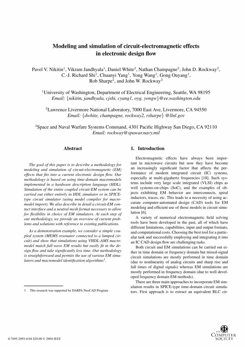
For demonstration of modeling flow methodology de-scribed above, consider a simple example: MEMS res-onator (micromachined comb structure, approximately1.5 mm × 0.5 mm in size, and positioned in free-space)driven by an external voltage source as shown in Fig-ure 4. This MEMS structure represents an electromagneticsubsystem and can be thought of as part of a larger inte-grated package. The voltage source and the resistor repre-sent a lumped circuit subsystem (which can be any transis-tor circuit).
2 Trademark of Mathworks, Inc.
0-7695-2093-6/04 $20.00 2004 IEEE
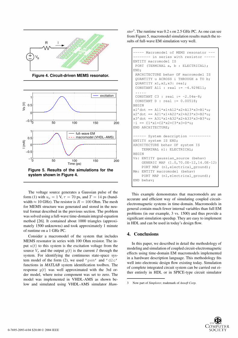
Figure 4. Circuit-driven MEMS resonator.
0 50 100 150 200−0.5
0
0.5
1
Vs
(V)
excitation
0 50 100 150 200−1
−0.5
0
0.5
1
Time (ps)
I (m
A)
full−wave EMmacromodel (VHDL−AMS)
Figure 5. Results of the simulations for thesystem shown in Figure 4.
The voltage source generates a Gaussian pulse of theform (1) with uo = 1 V, τ = 70 ps, and T = 14 ps (band-width ≈ 10 GHz). The resistor is R = 100 Ohm. The meshfor MEMS structure was generated and stored in the neu-tral format described in the previous section. The problemwas solved using a full-wave time-domain integral-equationmethod [26]. It contained about 1000 triangles (approxi-mately 1500 unknowns) and took approximately 1 minuteof runtime on a 1 GHz PC.
Consider a macromodel of the system that includesMEMS resonator in series with 100 Ohm resistor. The in-put u(t) to this system is the excitation voltage from thesource Vs and the output y(t) is the current I through thesystem. For identifying the continuous state-space sys-tem model of the form (2), we used ’pem’ and ’d2c’functions in MATLAB system identification toolbox. Theresponse y(t) was well approximated with the 3rd or-der model, where noise component was set to zero. Themodel was implemented in VHDL-AMS as shown be-low and simulated using VHDL-AMS simulator Ham-
ster3. The runtime was 0.2 s on 2.5 GHz PC. As one can seefrom Figure 5, macromodel simulation results match the re-sults of full-wave EM simulation very well.
----- Macromodel of MEMS resonator ----------- in series with resistor -----ENTITY macromodel ISPORT (TERMINAL a, b : ELECTRICAL);END;ARCHITECTURE behav OF macromodel ISQUANTITY u ACROSS i THROUGH a TO b;QUANTITY x1,x2,x3: real;CONSTANT A11 : real := -4.929E11;.....CONSTANT C3 : real := -2.04e-8;CONSTANT D : real := 0.00518;BEGINx1’dot == A11*x1+A12*x2+A13*x3+B1*u;x2’dot == A21*x1+A22*x2+A23*x3+B2*u;x3’dot == A31*x1+A32*x2+A33*x3+B3*u;-i == C1*x1+C2*x2+C3*x3+D*u;END ARCHITECTURE;
------ System description ----------ENTITY system IS END;ARCHITECTURE behav OF system IS
TERMINAL n1: ELECTRICAL;BEGINVs: ENTITY gaussian_source (behav)
GENERIC MAP (1.0,70.0E-12,14.0E-12)PORT MAP (n1,electrical_ground);
Mm: ENTITY macromodel (behav)PORT MAP (n1,electrical_ground);
END behav;
This example demonstrates that macromodels are anaccurate and efficient way of simulating coupled circuit-electromagnetic systems in time-domain. Macromodels ingeneral contain much fewer internal variables than full EMproblems (in our example, 3 vs. 1500) and thus provide asignificant simulation speedup. They are easy to implementin HDL and can be used in today’s design flow.
4. Conclusions
In this paper, we described in detail the methodology ofmodeling and simulation of coupled circuit-electromagneticeffects using time-domain EM macromodels implementedin a hardware description language. This methodology fitswell into electronic design flow existing today. Simulationof complete integrated circuit system can be carried out ei-ther entirely in HDL or in SPICE-type circuit simulator
3 Now part of Simplorer, trademark of Ansoft Corp.
0-7695-2093-6/04 $20.00 2004 IEEE

(using HDL-to-SPICE model compiler). We have also de-fined a circuit-EM contact interface and a neutral geome-try meshing format that can be used by various electromag-netic solvers used in the design process.
For demonstration, we considered a simple coupled sys-tem (MEMS resonator connected to a lumped circuit) andshowed that VHDL-AMS macromodel simulation resultsmatch full-wave EM results but take significantly less timeto obtain. This shows that EM macromodeling is a very ef-fective way to include circuit-electromagnetic effects intosimulation. Implementing macromodels in a hardware de-scription language allows one to use them in the current ICdesign flow.
References
[1] R. Achar and M. S. Nakhla. Simulation of high-speed inter-connects. Proceedings of IEEE, 89(5):693–728, May 2001.
[2] N. J. Champagne. On attaching a wire to a triangulated sur-face. IEEE Antennas and Propagation Symposium Digest,1:54–57, June 2002.
[3] E. Christen and K. Bakalar. VHDL-AMS – a hardware de-scription language for analog and mixed-signal applications.IEEE Transactions on Circuits and Systems, 46(10):1263–1272, October 1999.
[4] S. Grivet-Talocia, I. S. Stievano, I. A. Maio, and F. Canavero.Time-domain and frequency-domain macromodeling: appli-cation to package structures. IEEE International Symposiumon Electromagnetic Compatibility, 2:570–574, August 2003.
[5] V. Jandhyala, Y. Wang, D. Gope, and C.-J. Shi. A surface-based integral-equation formulation for coupled electromag-netic and circuit simulation. IEEE Microwave and OpticalTechnology Letters, 34(2):103–106, July 2002.
[6] K. Kundert, H. Chang, D. Jefferies, G. Lamant, E. Malavasi,and F. Sendig. Design of mixed-signal systems-on-a-chip.IEEE Transactions on CAD of Integrated Circuits and Sys-tems, 19(12):1561 –1571, December 2000.
[7] L. Lemaitre, C. McAndrew, and S. Hamm. ADMS – auto-matic device model synthesizer. Proceedings of the IEEECustom Integrated Circuits Conference, pages 27–30, 2002.
[8] Y. Liu, L. T. Pileggi, and A. J. Strojwas. Ftd: frequencyto time domain conversion for reduced-order interconnectsimulation. IEEE Transactions on Circuits and Systems,48(4):500–506, April 2001.
[9] D. MacMillen, R. Camposano, D. Hill, and T. W. Williams.An industrial view of electronic design automation. IEEETransactions on CAD of Integrated Circuits and Systems,19(12):1428–1448, December 2000.
[10] G. Marrocco and F. Bardati. Time-domain macromodel ofplanar microwave devices by FDTD and moment expansion.IEEE Transactions on Microwave Theory and Techniques,49(7):1321–1328, July 2001.
[11] E. K. Miller. A selective survey of computational electro-magnetics. IEEE Transactions on Antennas and Propaga-tion, 36(9):1281–1305, September 1988.
[12] I. Miller and T. Cassagnes. Verilog-A and Verilog-AMS pro-vide a new dimension in modeling and simulation. Proceed-ings of the 2000 Third IEEE International Caracas Confer-ence on Devices, Circuits and Systems, pages C49/1–c49/6,March 2000.
[13] P. V. Nikitin, C. J.-R. Shi, and B. Wan. Modeling partial dif-ferential equations in VHDL-AMS. IEEE System-on-ChipConference, pages 345–348, September 2003.
[14] A. Odabasioglu, M. Celik, and L. T. Pileggi. PRIMA: pas-sive reduced-order interconnect macromodeling algorithm.IEEE Transactions on CAD of Integrated Circuits and Sys-tems, 17(8):645–654, August 1998.
[15] N. Orhanovic and N. Matsui. FDTD-SPICE analysis of high-speed cells in silicon integrated circuits. Proceedings ofElectronic Components and Technology Conference, pages347–352, 2002.
[16] D. Pederson. A historical review of circuit simulation. IEEETransactions on Circuits and Systems, 31(1):103–111, Jan-uary 1984.
[17] B. F. Romanowicz. Methodology for the modeling and simu-lation of microsystems. Kluwer Academic Publishers, 1998.
[18] A. E. Ruehli and A. Cangellaris. Progress in the method-ologies for the electrical modeling of interconnects and elec-tronic packages. Proceedings of IEEE, 89(5):740–771, May2001.
[19] J. J. Sanchez-Gasca, K. Clark, N. W. Miller, H. Okamoto,A. Kurita, and J. Chow. Identifying linear models from timedomain simulations. IEEE Computer Applications in Power,10(2):26–30, April 1997.
[20] K. Seok-Yoon, N. Gopal, and L. T. Pillage. Time-domain macromodels for VLSI interconnect analysis. IEEETransactions on CAD of Integrated Circuits and Systems,13(10):1257–1270, October 1994.
[21] R. Sharpe, J. B. Grant, N. J. Champagne, W. A. Johnson,R. E. Jorgenson, D. R. Wilton, W. J. Brown, and J. W.Rockway. EIGER: Electromagnetic Interactions GEneRal-ized. IEEE Antennas and Propagation Symposium Digest,4(12):2366–2369, July 1997.
[22] I. A. Tsukerman, A. Konrad, G. Meunier, and J. C. Sabon-nadiere. Coupled field-circuit problems: trends and accom-plishments. IEEE Transactions on Magnetics, 29(2):1701–1704, August 1992.
[23] B. Wan, B. Hu, L. Zhou, and C.-J. R. Shi. MCAST: anabstract-syntax-tree based model compiler for circuit simula-tion. Proceedings of IEEE Custom Integrated Circuits Con-ference, 2003.
[24] D. A. White. Orthogonal vector basis functions for time do-main finite element solution of the vector wave equation.IEEE Transactions on Magnetics, 35(3):1458–1461, May1999.
[25] D. A. White and M. Stowell. Full wave simulation of elec-tromagnetic coupling effects in RF and mixed-signal IC’s us-ing time domain finite element method. IEEE Transactionson Microwave Theory and Techniques, submitted.
[26] C. Yang and V. Jandhyala. A time domain surface integraltechnique for mixed electromagnetic and circuit simulation.Electrical Performance of Electronic Packaging Conference,pages 41–44, 2002.
0-7695-2093-6/04 $20.00 2004 IEEE