
Modeling and Analysis of Inter-Copter Missile Guidance and ...
5
International Research Journal of Engineering and Technology (IRJET) e-ISSN: 2395-0056 Volume: 08 Issue: 03 | Mar 2021 www.irjet.net p-ISSN: 2395-0072 © 2021, IRJET | Impact Factor value: 7.529 | ISO 9001:2008 Certified Journal | Page 2661 Modeling and Analysis of Inter-Copter Missile Guidance and Control System using MATLAB Pratham Purkait 1 1 B.Tech student, Dept. of Mechanical Engineering, Delhi Technological University, Shahbad Daulatpur, Delhi, India. ---------------------------------------------------------------------***--------------------------------------------------------------------- Abstract - Inter-copter or anti-ballistic missile is a surface-to-air missile that is generally designed to counter potential threats in a particular area. It is a system that is designed to destroy any ballistic targets like missiles or fighter jets. The objective of the paper is to study and simulate a missile to hit its target. The concept of the flight control system is developed which helps the missile to activate the steering commands produced by the guidance system.The modeling of the Inter-copter missile was done with the famous concept of proportional navigation guidance law that predicts the line of sight of 2 bodies doesn’t change when they approach each other. The modeling was done with MATLAB-Simulink. The test result shows that the missile will launch when the target is 200m ahead and will strike the target within a given period. The position-time graph is obtained which shows the position of target and missile intersecting each other. Key Words: Proportional navigation guidance, Line of sight, acceleration, Autopilot. 1. INTRODUCTION Guided missiles are like the backbone of all weapons in today’s modern world of war. Due to technological advancement in the developing process of guided missiles there is a significant increase in the accuracy of military weapons. The application of automatic control is vast this includes Underwater Homing Torpedoes, Surface-to- Surface Aerodynamic Guided Missiles, Intercontinental Ballistic Missiles, Air-to-Air Guided Missiles, Surface-to-Air Guided Missiles e.t.c. Every missile guidance system is governed by a flight path control system. The Flight-path control systems help the missile to maintain a desired altitude on the commanded flight path by controlling the missile pitch, roll and yaw motion. The control system works on auto-pilot which eliminates the fluctuation and damping caused by air resistance thus prevent the missile to deflect from its ordered flight path. Hence the control system determine the flight path necessary for target interception and maintain a proper altitude and velocity [2]. 1.1 Phases of guidance There are a total of three phases of guidance system: Boost phase, Mid-course phase, Terminal phase. I)Boost phase: In this phase the missile is accelerated to the flight speed by booster components followed by onboard Inertial guidance processing and arriving at a pre- calculated point at the end of boost. II)Mid-course: This is the longest phase in terms of distance and time. During this phase off board target tracking and guidance processing is done to maintain a desired course. The aim is to bring the missile close to target by managing the trajectory and proper energy. III)Terminal phase: This is the last phase of missile guidance which requires high degree of accuracy as well as fast response rate towards the guidance signals. The missile performance plays a significant role which need to be monitor continuously. The final impact will be a function of velocity and air-frame design. The missile must be able to strike the target within given period of time [1]. Figure 1: Different phases of guidance system [1] 1.2 Types of Guidance law Missile guidance system is classified into two main categories: electromagnetic guidance system which are man made. It consists of control guidance and homing guidance missiles. The other one is hybrid guidance which is a combination of command guidance and semi-active homing guidance. This paper focuses on four important guidance laws that are: Pursuit guidance, Proportional navigation guidance, LQ-optimal guidance and Q-kappa guidance. I) Pursuit guidance - Pursuit guidance law states that missile velocity vector is always directed towards the target and the rate at which the missile will turn is always equal to the rate of turn of line of sight. The missile constantly follow the line of sight of the target and the total path traced is called the total pursuit [5].
Transcript of Modeling and Analysis of Inter-Copter Missile Guidance and ...

International Research Journal of Engineering and Technology (IRJET) e-ISSN: 2395-0056
Volume: 08 Issue: 03 | Mar 2021 www.irjet.net p-ISSN: 2395-0072
© 2021, IRJET | Impact Factor value: 7.529 | ISO 9001:2008 Certified Journal | Page 2661
Modeling and Analysis of Inter-Copter Missile Guidance and Control
System using MATLAB
Pratham Purkait1
1B.Tech student, Dept. of Mechanical Engineering, Delhi Technological University, Shahbad Daulatpur, Delhi, India. ---------------------------------------------------------------------***---------------------------------------------------------------------
Abstract - Inter-copter or anti-ballistic missile is a surface-to-air missile that is generally designed to counter potential threats in a particular area. It is a system that is designed to destroy any ballistic targets like missiles or fighter jets. The objective of the paper is to study and simulate a missile to hit its target. The concept of the flight control system is developed which helps the missile to activate the steering commands produced by the guidance system.The modeling of the Inter-copter missile was done with the famous concept of proportional navigation guidance law that predicts the line of sight of 2 bodies doesn’t change when they approach each other. The modeling was done with MATLAB-Simulink. The test result shows that the missile will launch when the target is 200m ahead and will strike the target within a given period. The position-time graph is obtained which shows the position of target and missile intersecting each other.
Key Words: Proportional navigation guidance, Line of sight, acceleration, Autopilot.
1. INTRODUCTION Guided missiles are like the backbone of all weapons in today’s modern world of war. Due to technological advancement in the developing process of guided missiles there is a significant increase in the accuracy of military weapons. The application of automatic control is vast this includes Underwater Homing Torpedoes, Surface-to-Surface Aerodynamic Guided Missiles, Intercontinental Ballistic Missiles, Air-to-Air Guided Missiles, Surface-to-Air Guided Missiles e.t.c. Every missile guidance system is governed by a flight path control system. The Flight-path control systems help the missile to maintain a desired altitude on the commanded flight path by controlling the missile pitch, roll and yaw motion. The control system works on auto-pilot which eliminates the fluctuation and damping caused by air resistance thus prevent the missile to deflect from its ordered flight path. Hence the control system determine the flight path necessary for target interception and maintain a proper altitude and velocity [2].
1.1 Phases of guidance
There are a total of three phases of guidance system: Boost phase, Mid-course phase, Terminal phase.
I)Boost phase: In this phase the missile is accelerated to the flight speed by booster components followed by onboard Inertial guidance processing and arriving at a pre-calculated point at the end of boost.
II)Mid-course: This is the longest phase in terms of distance and time. During this phase off board target tracking and guidance processing is done to maintain a desired course. The aim is to bring the missile close to target by managing the trajectory and proper energy.
III)Terminal phase: This is the last phase of missile guidance which requires high degree of accuracy as well as fast response rate towards the guidance signals. The missile performance plays a significant role which need to be monitor continuously. The final impact will be a function of velocity and air-frame design. The missile must be able to strike the target within given period of time [1].
Figure 1: Different phases of guidance system [1]
1.2 Types of Guidance law Missile guidance system is classified into two main categories: electromagnetic guidance system which are man made. It consists of control guidance and homing guidance missiles. The other one is hybrid guidance which is a combination of command guidance and semi-active homing guidance. This paper focuses on four important guidance laws that are: Pursuit guidance, Proportional navigation guidance, LQ-optimal guidance and Q-kappa guidance. I) Pursuit guidance - Pursuit guidance law states that missile velocity vector is always directed towards the target and the rate at which the missile will turn is always equal to the rate of turn of line of sight. The missile constantly follow the line of sight of the target and the total path traced is called the total pursuit [5].
International Research Journal of Engineering and Technology (IRJET) e-ISSN: 2395-0056
Volume: 08 Issue: 03 | Mar 2021 www.irjet.net p-ISSN: 2395-0072
© 2021, IRJET | Impact Factor value: 7.529 | ISO 9001:2008 Certified Journal | Page 2662
II) Proportional guidance law - This is one of the most widely used guidance law for short-mid range targets. This law states that the line of sight from the missile and the target remains parallel throughout the entire journey. Thus the rate of change of direction of missile is proportional to rate of change of direction of target [2]. III) LQ-optimal guidance -This law is based on the fact that the terminal acceleration almost approaches to zero as the distance between missile and target keeps on reducing. For practical application, the lateral acceleration is highly restricted. Hence, this law helps the missile to reduce the terminal miss distance even if the lateral acceleration is limited [3]. IV) Q-kappa guidance - Kappa guidance is used to optimize the the second phase that is mid-course trajectory of a missile to maximize the terminal velocity. The probability of hitting the target in this case is maximum. However this is a complex method and a lot of approximations are made in the derivation making it sub-optimal [4].
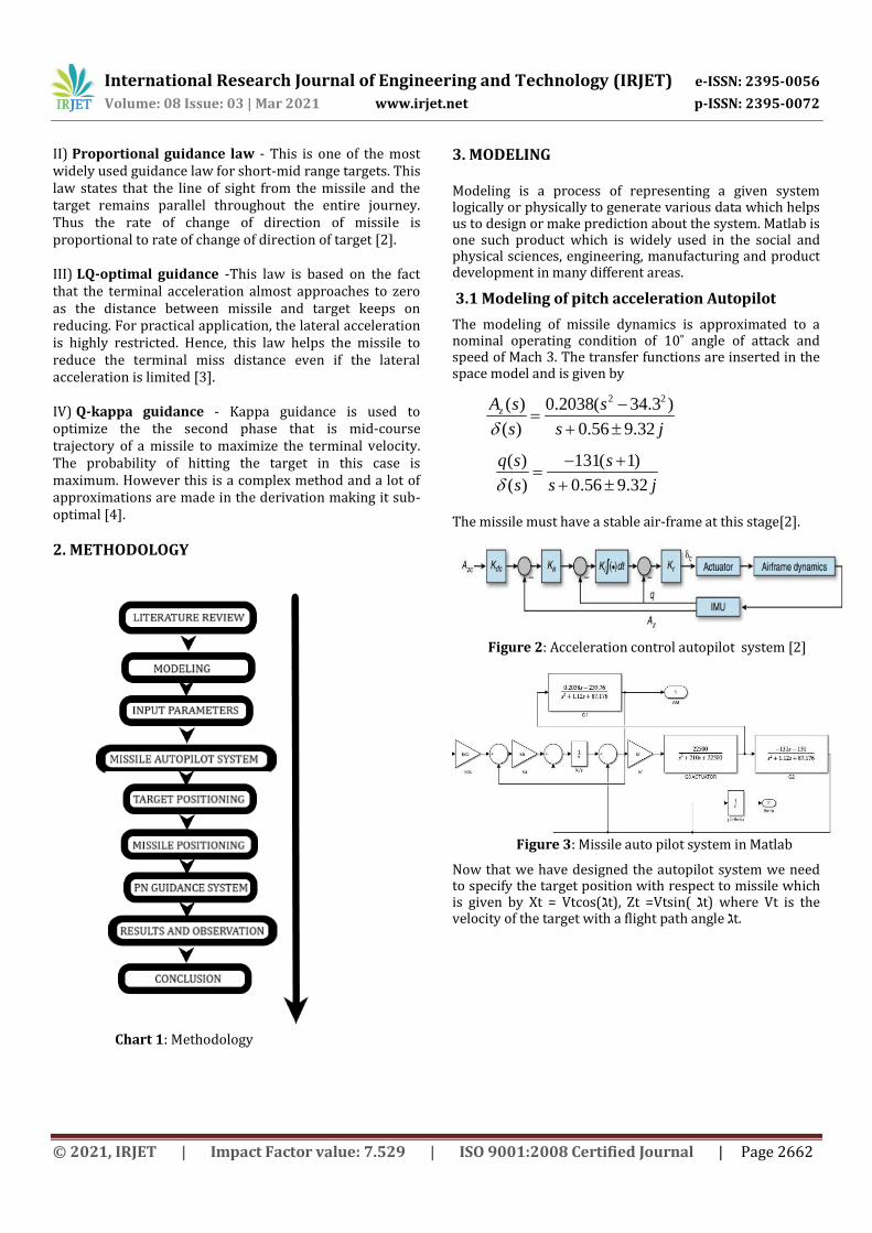
2. METHODOLOGY
Chart 1: Methodology
3. MODELING Modeling is a process of representing a given system logically or physically to generate various data which helps us to design or make prediction about the system. Matlab is one such product which is widely used in the social and physical sciences, engineering, manufacturing and product development in many different areas.
3.1 Modeling of pitch acceleration Autopilot
The modeling of missile dynamics is approximated to a nominal operating condition of 10˚ angle of attack and speed of Mach 3. The transfer functions are inserted in the space model and is given by
2 2( ) 0.2038( 34.3 )
( ) 0. 9.36 25
z
j
A s s
s s
( ) 131( 1)
( ) 0 6 9..5 32 j
q s s
s s
The missile must have a stable air-frame at this stage[2].
Figure 2: Acceleration control autopilot system [2]
Figure 3: Missile auto pilot system in Matlab
Now that we have designed the autopilot system we need to specify the target position with respect to missile which is given by Xt = Vtcos(ℷt), Zt =Vtsin( ℷt) where Vt is the velocity of the target with a flight path angle ℷt.

International Research Journal of Engineering and Technology (IRJET) e-ISSN: 2395-0056
Volume: 08 Issue: 03 | Mar 2021 www.irjet.net p-ISSN: 2395-0072
© 2021, IRJET | Impact Factor value: 7.529 | ISO 9001:2008 Certified Journal | Page 2663
Figure 4: Target positioning
Based on the target position the launch logic is set. When t=0 the target is behind the missile and it is approaching towards the missile. When the target is at a distance of 200m behind the missile it will launch with a particular flight path angle ℷ(0).
Figure 5: Missile positioning
The missile position is given by Xm = Vmcos(ℷm) and Zm= Vmsin(ℷm), where Vm is the missile velocity and ℷm is the flight path angle for the missile.
3.2 Modeling of PN guidance law
The figure represents a 2-D planar guidance system in which A = acceleration, V= speed, ℷ = flight path angle, R = range, M = missile, T = target.
Figure 6 : Planar guidance[1]
Figure 7: PN guidance system
From proportional navigation guidance law we have
Aℷ = N*Vc*(dℷ/dt) or Am = N*Vm*(dℷ/dt)
Vm = Missile velocity
Vc = closing velocity = dR/dt
For intercept to happen we need dR/dt < 0
dℷ/dt = Rate of change of line of sight
N = Proportional Navigation guidance constant (3-5)
The formula used is Am = N*Vm*(dℷ/dt), as the control system set-point is Am = Azc, that is the acceleration is perpendicular to velocity vector.
Table -1: Initial conditions
Assumptions: The seeker dynamics is ignored in the process that is laser semi-active homing, passive homing, IR homing etc.
Missile velocity Vm(0) 0 m/s Missile position
Xm(0)
2000 m
Flight path angle
ℷm (0) (missile)
80 deg Target position
Zt(0)
20000 m
Target velocity Vt(0) 600 m/s PN guidance
activation at
Vm =
950 m/s
Flight path angle ℷt (0)
( Target)
(-2.5-5) deg
Vm (t) final 1021
m/s
Missile will launch when | Xt - Xm|
< 200 m (Xt,Zm)
(0,0)

International Research Journal of Engineering and Technology (IRJET) e-ISSN: 2395-0056
Volume: 08 Issue: 03 | Mar 2021 www.irjet.net p-ISSN: 2395-0072
© 2021, IRJET | Impact Factor value: 7.529 | ISO 9001:2008 Certified Journal | Page 2664
Figure 8: Pictorial representation of setup
The implementation of PN guidance is an important step to ensure that the missile does not turn steep angles and to avoid damage to the actuators.
The commanded acceleration Aℷ is constrained, this is done to keep the actuator requirement low and avoid steep angles. The missile actuator like fin, canard etc, has constraints in reality which is not capable of achieving very high commanded accelerations. Based on the rate of change of flight path angle, the vector Aℷ will be positive or negative.
From Coriolis equation: d(ℷm)/dt = Am/Vm or Aℷ/Vℷ (LOS)
Figure 9: Overall system
4. RESULTS
Chart 2: Missile and Target position
Chart 3: Response to unit step function (Autopilot)
Chart 4: Missile velocity
4. CONCLUSIONS The modeling and analysis of inter-copter missiles are done with PN guidance law using Matlab. Various guidance laws and different phases were discussed. For simulation purposes, we take standard values from different journals and proceed step by step. At first missile auto-pilot system is designed and measured the output with a unit step function. Secondly, the positioning of target and missile is specified with respect to each other and apply PN guidance law which will activate only when the speed of the missile exceeds 950 m/s. The results obtained were shown in the charts. Chart 2 shows the position of target and missile which intersects at a point, this means that the missile will hit the target with a given period of time. The final missile velocity is set to 1021 m/s which is shown in chart 4 and will maintain a constant cruise speed. The missile will launch when the target is 200 m behind the missile position. The missile will hit the target at height 0f 19200 m in 32 sec
International Research Journal of Engineering and Technology (IRJET) e-ISSN: 2395-0056
Volume: 08 Issue: 03 | Mar 2021 www.irjet.net p-ISSN: 2395-0072
© 2021, IRJET | Impact Factor value: 7.529 | ISO 9001:2008 Certified Journal | Page 2665
approximately. Hence from the above observation we can conclude that the simulation is successfully performed.
REFERENCES [1] Neil F. Palumdo, Ross A. Blauwkamp and Justin M.
Llyod, “Basic principle of homing guidance,” vol. 29, 2010.
[2] Paul B. Jackson, “Overview of missile flight control system,” vol. 29, 2010.
[3] Chang Kyung Ryoo, H. Jin Kim, Min Jea Tahk and JinIk Lee “Optimal guidance law: Impact angle and terminal lateral acceleration control,” Inha University, Incheon, 402-751, Korea.
[4] Demetrios Serakos and Ching Fang Lin, “Linearized kappa guidance,” Combat system department, Dahlgren division naval surface warfare centre, 1996.
[5] Yilmaz Baris Erkan and Nevan Sengil, “Comparison between the pursuit guidance and the proportional navigation guidance laws regarding a predetermined scenario,” pp. 162-165, Ankara, Turkey, 2018.
[6] D. Ghose, “Navigation guidance control,” Bangalore: Nptel, 2012, pp. 103-109.
[7] R. Yanushevsky, “Modern missile guidance,” CRC Press, 2007.
[8] R. Goodstein, “Guidance law applicability to missile closing guidance and control of tactical missiles,” AGARD, France, 1972.
[9] D. Perh, “A study into advanced guidance laws using computational methods,” Master thesis, NPGS, Monetary, California, 2011.
[10] G.H. Lindsley and D.R. Redmon, “Tactical missile design,” NPGS, 1985, pp. 9-12.