![Freon 410A · 2019. 10. 17. · New tables of the thermodynamic properties of Freon™ 410A refrigerant (ASHRAE designation: R-410A [50/50]), have been developed and are presented](https://static.fdocuments.us/doc/165x107/60b627c139ff3c2213239567/freon-410a-2019-10-17-new-tables-of-the-thermodynamic-properties-of-freona.jpg)
Model WGZ-D • 30 to 200 Tons • R-410A • 60Hz/50Hz Packaged ...
86
Water-Cooled Scroll-Compressor Chillers Catalog 613-2 Model WGZ-D • 30 to 200 Tons • R-410A • 60Hz/50Hz Packaged Chillers and Condenserless Units
Transcript of Model WGZ-D • 30 to 200 Tons • R-410A • 60Hz/50Hz Packaged ...

Water-Cooled Scroll-Compressor Chillers Catalog 613-2
Model WGZ-D • 30 to 200 Tons • R-410A • 60Hz/50Hz
Packaged Chillers and Condenserless Units
2 CAT 613-2
Introduction. . . . . . . . . . . . . . . . . . . . . . . . . . . . . . . . 3Features and Benefits . . . . . . . . . . . . . . . . . . . . . . . 4Application Considerations. . . . . . . . . . . . . . . . . . . 7Selection Procedure. . . . . . . . . . . . . . . . . . . . . . . . 12Performance Data. . . . . . . . . . . . . . . . . . . . . . . . . . 16Part Load Performance Data (60 Hz) . . . . . . . . . . 32Part Load Performance Data (50 Hz) . . . . . . . . . . 34WGZ-DA with Matching ACH Condensers . . . . . . 36Pressure Drop Data . . . . . . . . . . . . . . . . . . . . . . . . 37
Physical Data - Packaged Units . . . . . . . . . . . . . . 39Physical Data - Units Less Condenser . . . . . . . . 42Dimensions - Packaged . . . . . . . . . . . . . . . . . . . . 44Dimensions - Condenserless . . . . . . . . . . . . . . . . 48Lifting and Mounting Weights . . . . . . . . . . . . . . . 53Electrical Data . . . . . . . . . . . . . . . . . . . . . . . . . . . . 56Sound Data . . . . . . . . . . . . . . . . . . . . . . . . . . . . . . 74Options and Accessories . . . . . . . . . . . . . . . . . . . 78Engineering Guide Specification . . . . . . . . . . . . . 79
Hazard Identification
Note: Cover photograph is a 130-ton WGZ without suction insulation for clarity.
Manufactured in an ISO certified facility
© 2014 Daikin Applied. Illustrations and data cover the Daikin Applied product at the time of publication and we reserve the right to make changes in design and construction at anytime without notice.
DANGER
Dangers indicate a hazardous situation which will result in death or serious injury if not avoided.
WARNING
Warnings indicate potentially hazardous situations, which can result in property damage, severe personal injury, or death if not avoided.
CAUTION
Cautions indicate potentially hazardous situations, which can result in personal injury or equipment damage if not avoided.
Modbus
*AHRI Certification and ETL Listing apply to 60Hz packaged models only.
CAT 613-2 3
IntroductionIntroduction
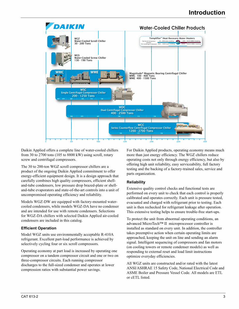
Daikin Applied offers a complete line of water-cooled chillers from 30 to 2700 tons (105 to 8800 kW) using scroll, rotary screw and centrifugal compressors.
The 30 to 200-ton WGZ scroll compressor chillers are a product of the ongoing Daikin Applied commitment to offer energy-efficient equipment design. It is a design approach that carefully combines high quality compressors, efficient shell-and-tube condensers, low pressure drop brazed-plate or shell-and-tube evaporators and state-of-the-art controls into a unit of uncompromised operating efficiency and reliability.
Models WGZ-DW are equipped with factory-mounted water-cooled condensers, while models WGZ-DA have no condenser and are intended for use with remote condensers. Selections for WGZ-DA chillers with selected Daikin Applied air-cooled condensers are included in this catalog.
Efficient Operation
Model WGZ units use environmentally acceptable R-410A refrigerant. Excellent part-load performance is achieved by selectively cycling four or six scroll compressors.
Operating economy at part load is increased by operating one compressor on a tandem compressor circuit and one or two on three-compressor circuits. Each running compressor discharges to the full-sized condenser and operates at lower compression ratios with substantial power savings.
For Daikin Applied products, operating economy means much more than just energy efficiency. The WGZ chillers reduce operating costs not only through energy efficiency, but also by offering high unit reliability, easy serviceability, full factory testing and the backing of a factory-trained sales, service and parts organization.
Reliability
Extensive quality control checks and functional tests are performed on every unit to check that each control is properly calibrated and operates correctly. Each unit is pressure tested, evacuated and charged with refrigerant prior to testing. Each unit is then rechecked for refrigerant leakage after operation. This extensive testing helps to ensure trouble-free start-ups.
To protect the unit from abnormal operating conditions, an advanced MicroTech™ II microprocessor controller is installed as standard on every unit. In addition, the controller takes preemptive action when certain operating limits are approached, keeping the unit on line and sending an alarm signal. Intelligent sequencing of compressors and fan motors (on cooling towers or remote condenser models) as well as responding to external reset and load limit instructions optimize everyday efficiencies.
All WGZ units are constructed and/or rated with the latest ANSI/ASHRAE 15 Safety Code, National Electrical Code and ASME Boiler and Pressure Vessel Code. All models are ETL or cETL listed.
Water-Cooled Chiller Products
0 500 1000 1500 2000 2500 3000
WGZWater-Cooled Scroll Chiller30 - 200 Tons
WGSWater-Cooled Screw Chiller130 - 190 Tons
Magnitude® Magnetic Bearing Centrifugal ChillerWMC 100 - 400 TonsWME 400 - 1500 Tons
WSCSingle Centrifugal Compressor Chiller
200 - 1250 Tons
WDCDual Centrifugal Compressor Chiller
400 - 2500 Tons
WCCSeries Counterflow Centrifugal Compressor Chiller
1200 - 2700 Tons
15� - �255� tons �cooling
200� - �1200� tons �cooling 3000� - �18000� MBH �heating
320� - �3410� MBH �heatingcooling
s cooling 3000 - 1
320 - 3
Templifier™ Heat Recovery Water HeatersTGZ (Scroll Compressor)
TSC (Centrifugal Compressor)
063 079 087 100 113 126
063 079 087 100 113 126
WMC WME
100 113 126
E
4 CAT 613-2
Features and Benefits
Flexibility
The WGZ chillers come in 16 sizes between 30 and 200 nominal tons (105 and 700 kW). This small capacity increment allows a selection that can closely match the required job capacity.
Several options for power connections can match field requirements.
Many optional features can be added to fit job requirements. A unit-mounted non-fused disconnect switch eliminates the need for a field installed disconnect. Phase failure/reversal protection and acoustical sound blankets around each compressor are among the many optional features that can be factory installed.
Latest Control Technology
These units have the latest control technology through utilization of Daikin Applied's MicroTech II® microprocessor.
Integrating with your building automation system is easy with the Open Choice™ feature using LonTalk®, BACnet® or Modbus® network communication, via field mounting of a small communication module to the unit controller.
LEED® Points
Developed by the U.S. Green Building Council (USGBC) in 1998, Leadership in Energy and Environmental Design (LEED®) is an internationally recognized certification program and intends to provide building owners and operators a consistent structure for identifying and implementing practical and measurable green building design, construction, operations and maintenance solutions. For building owners who want to pursue LEED Green Building Certification, most WGZ-D models will qualify for the Energy and Atmosphere Credit 4, Enhanced Refrigerant Management worth 2 points. Contact your local sales representative for more details.
Chiller Nomenclature
Features and Benefits
Unit Design Features
The Daikin WGZ water chillers are completely factory assembled, piped, wired and shipped in one piece, ready for field connection of power, water piping, and refrigerant piping on remote air or evaporative cooled condenser models. Each chiller consists of compressors, insulated brazed plate or shell-and-tube evaporator and centralized electrical control panel containing all necessary equipment protection and operating controls. Packaged units (“DW”) come complete with mounted, water-cooled condensers with integral subcooler circuits. Condenserless units (“DA”) are provided without condensers to allow for remote installation of air-cooled or evaporative condensing equipment.
Compressors
WGZ chillers use rugged hermetic scroll compressors constructed with an integral cast iron frame, cast iron scrolls, coated bearings, and three oil filtration devices for each compressor. Compressors are placed in tandem or trio arrangements to allow for optimized capacity modulation, resulting in excellent part-load efficiency. Each refrigerant circuit has specially designed oil and gas equalization lines to control oil migration.
The design also offers radial and axial compliance (no tip seals), a large internal volume for liquid handling, a removable suction screen, and a rotary dirt trap and oil screen. In addition,
the compressor is self-compensating for wear, handles liquid and debris, and inherently yields high efficiency.
Units are available in 60-hertz with voltages from 208 to 575 volt, operating at 3500 RPM, and 50-hertz, 400 volt models.
Evaporator
ModelsWGZ030D through WGZ130D
Evaporators are compact, high efficiency, two-circuit, brazed-plate type heat exchanger consisting of parallel type 304 stainless steel plates, with a design water-side pressure of 653 psi.
Evaporators are designed and constructed according to, and listed by, Underwriters Laboratories (UL). The evaporators do not have vent or drain connections and they must be supplied in the field piping.
Models WGZ150D through WGZ200D
The evaporator is direct-expansion, shell and tube type with water flowing in the baffled shell side and refrigerant flowing through the tubes. The water side working pressure is 152 psig (1048 kPa). Each evaporator is designed, constructed, inspected, and stamped according to the requirements of the ASME Boiler and Pressure Vessel Code. Double thickness insulation is available as an option. Drain and vent connections are provided on the vessel.
W G Z XXX D W
Water-Cooled
Global DesignScroll CompressorNominal Tons
Condenser
Design Vintage
W = Standard PackagedA = Less Condenser
CAT 613-2 5
Features and Benefits
Water-Cooled CondensersThe WGZ-DW water-cooled condensers are cleanable shell and tube type with water in the tubes and two refrigerant circuits in the shell side, divided by a vertical, midpoint partition. Each condenser circuit is capable of holding the circuit's refrigerant charge and each circuit has its own charging and relief valves.
The condenser is constructed with a carbon steel shell and seamless integrally finned high efficiency copper tubes roller expanded into steel tubesheets. The water heads at each end have vent and drain connections and are removable. Also included is a liquid shutoff valve, purge valve, and relief valve per ANSI/ASHRAE Pressure Vessel Code, Section VIII. Water-side working pressure is 232 psi (1599 kPa). Standard condenser connections are located on the right end looking at the control panel. Optional left hand connections available.
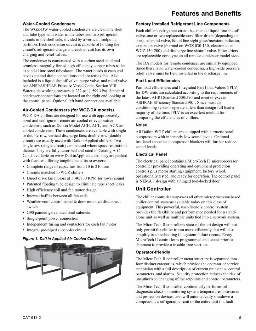
Air-Cooled Condensers (for WGZ-DA models)WGZ-DA chillers are designed for use with appropriately sized and configured remote air-cooled or evaporative condensers, such as Daikin Model ACH, ACL, and ACX air-cooled condensers. These condensers are available with single- or double-row, vertical discharge fans; double-row (double-circuit) are usually used with Daikin Applied chillers. Two single row (single circuit) can be used where space restrictions dictate. They are fully described and rated in Catalog A-C Cond, available on www.DaikinApplied.com. They are packed with features offering tangible benefits to owners:
• Complete range of capacities from 10 to 210 tons
• Circuits matched to WGZ chillers
• Direct drive fan motors at 1140/830 RPM for lower sound
• Patented floating tube design to eliminate tube sheet leaks
• High efficiency coil and fan motor design
• Internal baffles between all fan cells
• Weatherproof control panel & door-mounted disconnect switch
• G90 painted galvanized steel cabinets
• Single-point power connection
• Independent fusing and contactors for each fan motor
• Integral pre-piped subcooler circuit
Figure 1: Daikin Applied Air-Cooled Condenser
Factory Installed Refrigerant Line Components
Each chiller's refrigerant circuit has manual liquid line shutoff valve, one or two replaceable-core filter-driers (depending on size), solenoid valve, liquid line sight glass/moisture indicator, expansion valve (thermal on WGZ 030-130, electronic on WGZ 150-200) and discharge line shutoff valve. Filter-driers are replaceable-core type on all remote condenser model sizes.
The DA models for remote condenser are similarly equipped. Since there is no water-cooled condenser, a high-side pressure relief valve must be field installed in the discharge line.
Part Load Efficiencies
Part load efficiencies and Integrated Part Load Values (IPLV) for DW units are calculated according to the requirements of the latest AHRI Standard 550/590-and meet or exceed ASHRAE Efficiency Standard 90.1. Since most air conditioning systems operate at less than design full load a majority of the time, IPLV is an excellent method for comparing the efficiencies of chillers.
Noise
All Daikin WGZ chillers are equipped with hermetic scroll compressors with inherently low sound levels. Optional insulated acoustical compressor blankets will further reduce sound levels.
Electrical Panel
The electrical panel contains a MicroTech II microprocessor controller providing operating and equipment protection controls plus motor starting equipment, factory wired, operationally tested, and ready for operation. The control panel is NEMA 1 design with a hinged tool-locked door.
Unit Controller
The chiller controller surpasses all other microprocessor-based chiller control systems available today on this class of equipment. This powerful, user-friendly control system provides the flexibility and performance needed for a stand-alone unit as well as multiple units tied into a network system.
The MicroTech II controller's state-of-the-art design will not only permit the chiller to run more efficiently, but will also simplify troubleshooting if a system failure occurs. Every MicroTech II controller is programmed and tested prior to shipment to provide a trouble-free start-up.
Operator-friendly
The MicroTech II controller menu structure is separated into four distinct categories, which provide the operator or service technician with a full description of current unit status, control parameters, and alarms. Security protection reduces the risk of unauthorized changing of the setpoints and control parameters.
The MicroTech II controller continuously performs self-diagnostic checks, monitoring system temperatures, pressures and protection devices, and will automatically shutdown a compressor, a refrigerant circuit or the entire unit if a fault
6 CAT 613-2
Features and Benefits
occurs. The cause of the shutdown will be retained in memory and can be easily displayed in plain language for operator review. The MicroTech II chiller controller will also retain and display the time the fault occurred and the operating conditions that were present at the time of the fault, which is an extremely useful feature for troubleshooting. In addition to displaying alarm diagnostics, the MicroTech II chiller controller also provides the operator with a warning of pre-alarm conditions.
Staging
The four scroll compressors on models WGZ 030 to 130 are staged on and off as a function of leaving chilled water temperature, providing 4 steps of unloading. Models WGZ 150 to 200 have six capacity steps. Lead/lag is automatic and switched every ten starts.
Equipment Protection
The unit is protected by alarms that shut it down and require manual reset. It's also guarded by limit alarms that limit unit operation in response to some out-of-limit condition. Shut down alarms activate an alarm signal.
Shutdown Alarms• No evaporator water flow• No condenser flow• Low evaporator pressure• High condenser pressure• Motor protection system• Phase voltage protection (Optional)• Outside ambient temperature (For remote condenser
models, field wired sensor)• Evaporator freeze protection• Sensor failures
Limit Alarms• Condenser pressure stage down, unloads unit at high
discharge pressures• Low ambient lockout, shuts off unit at low ambient
temperatures• Low evaporator pressure hold, holds stage #1 until circuit
pressure rises• Low evaporator pressure unload, shuts off stage #2 per
circuit
Unit Enable Selection
Enables unit operation from keypad, digital input, or BAS.
Unit Mode Selection
Selects standard cooling, ice, glycol, or test operation mode to correctly control staging and other functions.
• Digital Inputs• Unit off switch• Remote start/stop• Flow switch• Ice mode switch, converts control operation and set-
points for ice production• Motor protection
Digital Outputs• Shutdown alarm; field wired, activates on an alarm con-
dition and is off when alarm is cleared• Evaporator pump; field wired, starts pump when unit is
set to start• Twelve outputs for fan control on remote condenser
applications
Condenser fan control
On remote air-cooled condenser units, the MicroTech II controller provides control of up to four condenser fans for each of the two circuits. The control sequences condenser fans based on discharge pressure. This function may also be furnished as part of the condenser control.
Keypad/Display
A 4-line by 20 character/line LCD with 6-button keypad is mounted on the unit controller. Its layout is shown below.
Building Automation System (BAS) Interface
All MicroTech II controllers are capable of BAS communications, providing seamless integration and comprehensive monitoring, control, and two-way data exchange with industry standard protocols such as LONMARK , Modbus or BACnet. The BAS communication module can be ordered factory-mounted or can be field-mounted at any time after the chiller is installed.
Open Choice™ Benefits• Easily integrate into building automation system of choice• Factory-installed and tested communication module• Comprehensive point list for system integration, equipment
monitoring and alarm notification • Provides efficient equipment operation• Owner/designer selects BAS that best meets requirements• Comprehensive data exchange
Integration Made Easy
Daikin Applied unit controllers strictly conform to the guidelines of the LONMARK Interoperability Association and the BACnet Manufacturers Association. The control system has received:• LONMARK certification with optional LONMARK
communication module• BACnet certification pending
Protocol Options• BACnet MS/TP• LONMARK (FTT-10A)• BACnet IP• Modbus RTU• BACnet Ethernet
CAT 613-2 7
Application ConsiderationsApplication Considerations
Location and Space Requirements
WGZ-D units are designed for indoor application and must be located in a space where the operating and standby conditions are 40°F to 122°F (4.4°C to 50°C).
Provide clearance of 3 ft. (914 mm) on each side and end for piping and to provide space for servicing the unit. Provide sufficient clearance above the unit for component removal.
Provide clearance at either end of the unit to permit cleaning or removal of condenser tubes (see dimensional data). If a properly located door or window is provided in the wall at one end of the unit, the tubes may be able to be replaced through the opening provided.
Foundation
Mount the unit on a level concrete foundation. Floors must be strong enough to support the unit operating weight. If necessary, use structural supports to transfer the weight of the unit to the nearest beams.
Vibration Isolation
Optional rubber-in-shear or spring vibration mounts are recommended for upper floor installations or where compressor noises might be objectionable (next to occupied spaces such as offices, meeting rooms, etc.).
Pipe vibration eliminators may be required for water piping connected to the unit to minimize transmission of water or pump noise into occupied spaces.
System Water Volume
It is important to have adequate water volume in the system to provide an opportunity for the chiller to sense a load change, adjust to the change and stabilize. As the expected load change becomes more rapid, a greater water volume is needed. The system water volume is the total amount of water in the evaporator, air handling products and associated piping. If the water volume is too low, operational problems can occur, including rapid compressor cycling, rapid loading and unloading of compressors, erratic refrigerant flow in the chiller, improper motor cooling, shortened equipment life and other undesirable occurrences.
For normal comfort cooling applications where the cooling load changes relatively slowly, Daikin Applied recommends a minimum system volume of two to three times the flow rate (GPM). For example, if the design chiller flow rate is 120 GPM, we recommend a minimum system volume of 240 to 360 gallons.
For process applications where the cooling load can change rapidly, additional system water volume is needed. A process example would be the cooling of hot metal objects. The load would be very stable until the hot metal is dipped into the water tank. Then, the load would increase drastically.
Since there are many other factors that can influence performance, systems can successfully operate below these suggestions. However, as the water volume decreases below these values, the possibility of system instability increases.
Evaporator Variable Flow
Reducing evaporator flow in proportion to load can reduce system power consumption. Certain restrictions apply to the amount and rate of flow change. The rate of flow change should be a maximum of 10 percent of the change per minute. Do not reduce flow lower than the minimum flows listed in the evaporator pressure drop table, page 38.
Chilled Water Piping
If factory-installed flow switches are not ordered, install a flow switch in the horizontal piping of the system supply (evaporator outlet) water line.
Provide drain connections at low points in the system to permit complete drainage of the system. Locate air vents at the high points in the system to purge air out of the system. There are no vent or drain connections on the evaporator for models 030 to 130. Purge air from the water system before unit start-up to ensure adequate flow through the evaporator.
NOTE: Install a perforated metal basket strainer (0.062-inch perforations, 41% open area for models for WGZ 030 through 130, and a strainer with 0.125-inch perforations, 40% open area for WGZ 150 through 200) in the return chilled water line before the inlet to the evaporator.
Flush the system water piping thoroughly before making connections to the unit evaporator. Design the water piping so the chilled water circulating pump discharges into the evaporator inlet.
Install pressure gauges in the inlet and outlet water lines to the evaporator. Measure pressure drop through the evaporator to calculate proper flow. Vibration eliminators are recommended in both the supply and return water lines.
Insulate chilled water piping to reduce heat loss and prevent condensation.
8 CAT 613-2
Application Considerations
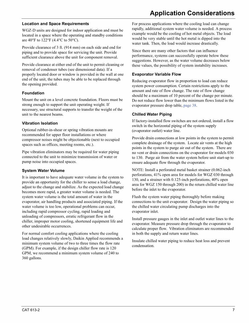
Figure 2: Typical Chilled Water Piping, models WGZ030-130 (Brazed Plate Evaporator)
Figure 3: Typical Chilled Water Piping, models WGZ150-200 (Shell & Tube type Evaporator)
Condenser Water
Be certain the condenser water enters the bottom connection of the condenser and exits the condenser from the top connection. Head pressure control must be provided if the entering condenser water can fall below 60°F (15°C). Install a 20-mesh strainer in the condenser inlet line. The WGZ condenser has two refrigerant circuits with a common condenser water circuit. This arrangement makes head pressure control with discharge pressure actuated control valves difficult.
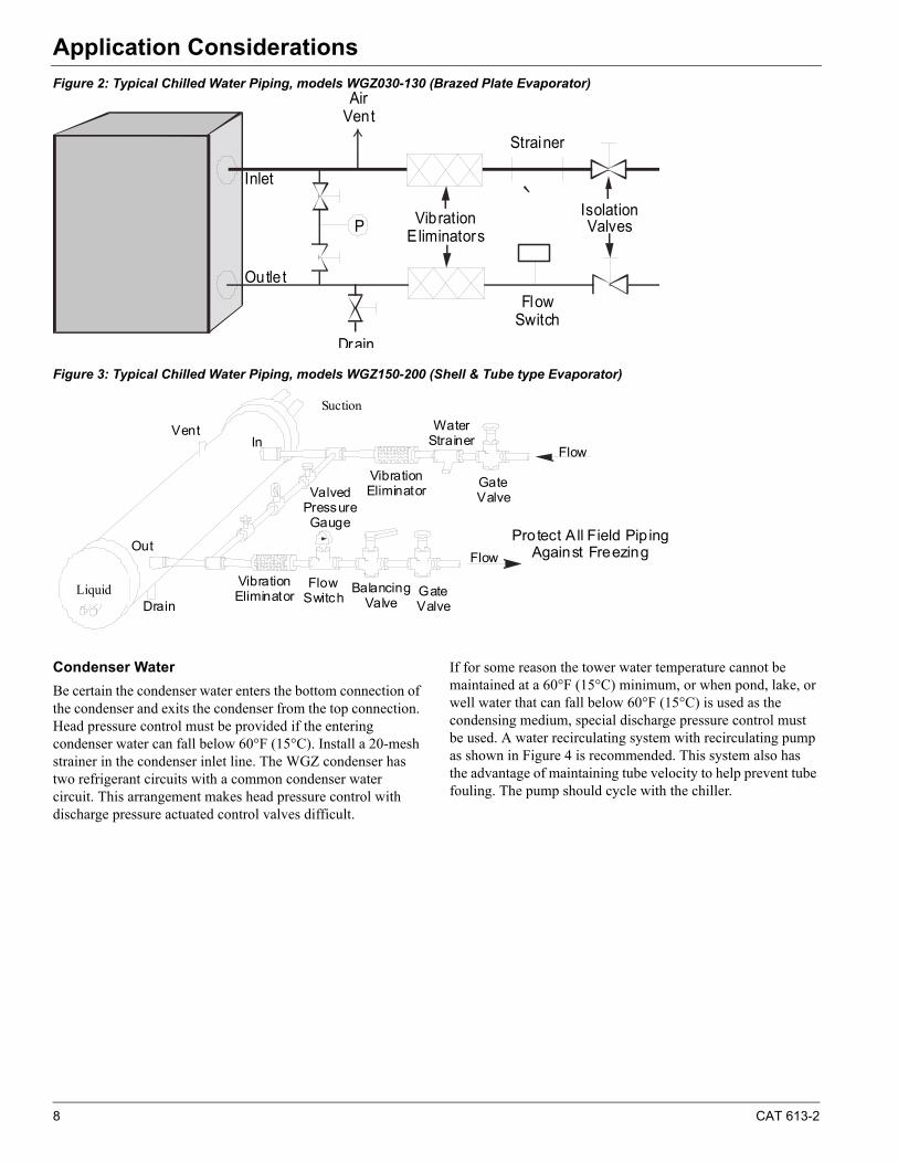
If for some reason the tower water temperature cannot be maintained at a 60°F (15°C) minimum, or when pond, lake, or well water that can fall below 60°F (15°C) is used as the condensing medium, special discharge pressure control must be used. A water recirculating system with recirculating pump as shown in Figure 4 is recommended. This system also has the advantage of maintaining tube velocity to help prevent tube fouling. The pump should cycle with the chiller.
AirVent
FlowSwitch
VibrationEliminators
Drain
Outle t
Inlet
PIsolationValves
Strainer
Vent
Drain
GateValve
WaterStrainer
VibrationEliminatorValved
Pressure Gauge
In
Out Protect All Field Pip ing Against Freezing
Flow
Vibration Eliminator
Flow Switch Balancing
ValveGateValve
Flow
Liquid
Suction
CAT 613-2 9
Application Considerations
Figure 4: Recirculating Discharge Pressure Control System
Ice Storage Applications
The MicroTech II controller has logic to change setpoints from the low ice-making mode to higher normal comfort cooling setpoints. It is important that the MicroTech II controller receive a 0 VAC (normal operation) to 24 VAC (ice mode) signal to convert from ice mode to normal operating mode. MicroTech II includes the logic to keep compressors fully loaded when operating in the ice mode. The double insulation thickness option is recommend to prevent sweating.
Two Pipe Systems
When the same two pipes are used for both heating and cooling water, several limitations should be observed. The maximum allowable temperature that the evaporator should experience in a non-operating mode is 100°F (38°C). For unit operation and system changeover from heating to cooling, the maximum allowable temperature entering the evaporator is 90 degrees Fahrenheit. System controls, provided by others, must prevent chiller operation until the loop temperature drops to 90°F (32°C).
Series or Parallel Operation
Consider system pressure drop when designing the water piping. Parallel piped systems have half of the total system flow going through the evaporator of each chiller, reducing the individual unit and total system pressure drop for a two chiller installation.
Series piped evaporators require that the total system water flows through both evaporators. Not only is the pressure drop through each evaporator increased but the pressure drops must be added together to obtain the total evaporator pressure drop. Series piped evaporators normally require larger circulating pumps for the chilled water system.
Electrical Connection
Every WGZ chiller requires field installation of the main supply power plus mandatory flow switch interlock, optional pump starter auxiliary contact interlock or other field-installed devices. A control circuit transformer installed at the factory eliminates the need for field installation of a separate 115V supply to the control circuit. However, if desired, a separate
115V field connection to the control circuit can be substituted. A system time clock and remote on-off switch can also be field installed.
See Figure 22, page 58 (packaged units) or Figure 23, page 59 (remote condenser models) for field control wiring diagrams. The diagrams shown represents all WGZ units; however, individual terminal numbers can vary between unit sizes. Each unit is provided with its specific wiring diagram in the control panel. All wiring must be done according to local and national codes.
Main Power Supply Disconnect Switch
Every WGZ unit with the standard single-point power supply is equipped with compressor circuit breakers as standard. Multiple-point power connection is available as an option using two power blocks. Circuit breakers are not available with the multiple-point option.
A factory-installed, non-fused disconnect switch (required to meet NEC Code for disconnects) with a through-the-door handle is available as an option with single or multiple-point power supply. The disconnect switch(s) is properly sized for the model and voltage supplied.
A field-supplied and installed remote disconnect switch can also be used.
Control Circuit
A control power transformer is standard equipment on WGZ units. Terminals are provided in the unit control center (terminals TB1 and TB1-20) for field connection to a remote 115V power supply if desired.
Terminals are also provided for field connection of the chilled water flow switch, unit time clock, ambient thermostat and/or remote on/off switch.
Condenser Pump Interlock
The condenser water pump should be interlocked to cycle with the compressor(s). This will prevent the refrigerant pressure from being overly depressed during the off cycle and allows the energy savings of pump shutdown. Interlock terminals are provided in the unit control panel.
Circuit #1 Outlet
Condenser
TemperatureControlValve
CondenserWater
Circuit #2 Outlet
Circuit #1 Inlet
Circuit #2 Inlet
10 CAT 613-2
Application Considerations
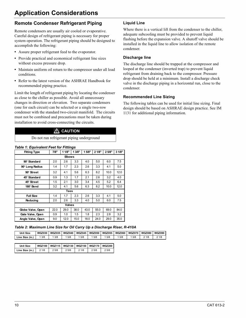
Remote Condenser Refrigerant Piping
Remote condensers are usually air cooled or evaporative. Careful design of refrigerant piping is necessary for proper system operation. The refrigerant piping should be designed to accomplish the following:
• Assure proper refrigerant feed to the evaporator.
• Provide practical and economical refrigerant line sizes without excess pressure drop.
• Maintain uniform oil return to the compressor under all load conditions.
• Refer to the latest version of the ASHRAE Handbook for recommended piping practice.
Limit the length of refrigerant piping by locating the condenser as close to the chiller as possible. Avoid all unnecessary changes in direction or elevation. Two separate condensers (one for each circuit) can be selected or a single two-row condenser with the standard two-circuit manifold. The circuits must not be combined and precautions must be taken during installation to avoid cross-connecting the circuits.
Liquid Line
Where there is a vertical lift from the condenser to the chiller, adequate subcooling must be provided to prevent liquid flashing before the expansion valve. A shutoff valve should be installed in the liquid line to allow isolation of the remote condenser.
Discharge line
The discharge line should be trapped at the compressor and looped at the condenser (inverted trap) to prevent liquid refrigerant from draining back to the compressor. Pressure drop should be held at a minimum. Install a discharge check valve in the discharge piping in a horizontal run, close to the condenser.
Recommended Line Sizing
The following tables can be used for initial line sizing. Final design should be based on ASHRAE design practice. See IM 1131 for additional piping information.
Table 1: Equivalent Feet for Fittings
Table 2: Maximum Line Size for Oil Carry Up a Discharge Riser, R-410A
CAUTION
Do not run refrigerant piping underground
Fitting Type 7/8" 1 1/8" 1 3/8" 1 5/8" 2 1/8" 2 5/8" 3 1/8"
90º Standard 2.0 2.6 3.3 4.0 5.0 6.0 7.5
90º Long Radius 1.4 1.7 2.3 2.6 3.3 4.1 5.0
90º Street 3.2 4.1 5.6 6.3 8.2 10.0 12.0
45º Standard 0.9 1.3 1.7 2.1 2.6 3.2 4.0
45º Street 1.5 2.1 3.0 3.4 4.5 5.2 6.4
180º Bend 3.2 4.1 5.6 6.3 8.2 10.0 12.0
Full Size 1.4 1.7 2.3 2.6 3.3 4.1 5.0
Reducing 2.0 2.6 3.3 4.0 5.0 6.0 7.5
Globe Valve, Open 22.0 29.0 38.0 43.0 55.0 69.0 84.0
Gate Valve, Open 0.9 1.0 1.5 1.8 2.3 2.8 3.2
Angle Valve, Open 9.0 12.0 15.0 18.0 24.0 29.0 35.0
Valves
Elbows
Tees
Unit Size WGZ030 WGZ035 WGZ040 WGZ045 WGZ050 WGZ055 WGZ060 WGZ070 WGZ080 WGZ090
Line Size (in.) 1 3/8 1 3/8 1 5/8 1 5/8 1 5/8 1 5/8 1 5/8 1 5/8 2 1/8 2 1/8
Unit Size WGZ100 WGZ115 WGZ130 WGZ150 WGZ170 WGZ200
Line Size (in.) 2 1/8 2 5/8 2 5/8 2 1/8 2 5/8 2 5/8
CAT 613-2 11
Application Considerations
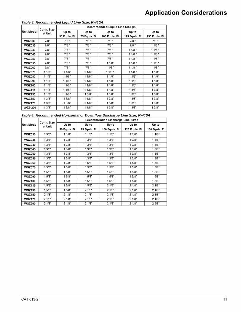
Table 3: Recommended Liquid Line Size, R-410A
Table 4: Recommended Horizontal or Downflow Discharge Line Size, R-410A
Up to Up to Up to Up to Up to
50 Equiv. Ft 75 Equiv. Ft 100 Equiv. Ft 125 Equiv. Ft 150 Equiv. Ft
WGZ030 7/8" 7/8 " 7/8 " 7/8 " 7/8 " 7/8 "
WGZ035 7/8" 7/8 " 7/8 " 7/8 " 7/8 " 1 1/8 "
WGZ040 7/8" 7/8 " 7/8 " 7/8 " 1 1/8 " 1 1/8 "
WGZ045 7/8" 7/8 " 7/8 " 7/8 " 1 1/8 " 1 1/8 "
WGZ050 7/8" 7/8 " 7/8 " 7/8 " 1 1/8 " 1 1/8 "
WGZ055 7/8" 7/8 " 7/8 " 1 1/8” 1 1/8 " 1 1/8 "
WGZ060 7/8" 7/8 “ 7/8 " 1 1/8 " 1 1/8 " 1 1/8 "
WGZ070 1 1/8” 1 1/8” 1 1/8 " 1 1/8 " 1 1/8 " 1 1/8”
WGZ080 1 1/8” 1 1/8 " 1 1/8 " 1 1/8” 1 1/8” 1 1/8”
WGZ090 1 1/8” 1 1/8 " 1 1/8 " 1 1/8” 1 1/8” 1 1/8”
WGZ100 1 1/8” 1 1/8 " 1 1/8 " 1 1/8” 1 1/8” 1 1/8”
WGZ115 1 1/8” 1 1/8 " 1 1/8 " 1 1/8” 1 3/8” 1 3/8”
WGZ130 1 1/8” 1 1/8 " 1 3/8” 1 1/8” 1 3/8” 1 3/8”
WGZ150 1 3/8” 1 3/8” 1 1/8 " 1 3/8” 1 3/8” 1 3/8”
WGZ170 1 3/8” 1 3/8” 1 1/8 " 1 3/8” 1 3/8” 1 3/8”
WGZ-200 1 3/8” 1 3/8” 1 1/8 " 1 3/8” 1 3/8” 1 3/8”
Unit Model
Recommended Liquid Line Size (in.)Conn. Size
at Unit
Up to Up to Up to Up to Up to
50 Equiv. Ft 75 Equiv. Ft 100 Equiv. Ft 125 Equiv. Ft 150 Equiv. Ft
WGZ030 1 3/8" 1 1/8" 1 1/8" 1 1/8" 1 1/8" 1 1/8"
WGZ035 1 3/8" 1 3/8" 1 3/8" 1 3/8" 1 3/8" 1 3/8"
WGZ040 1 3/8" 1 3/8" 1 3/8" 1 3/8" 1 3/8" 1 3/8"
WGZ045 1 3/8" 1 3/8" 1 3/8" 1 3/8" 1 3/8" 1 3/8"
WGZ050 1 3/8" 1 3/8" 1 3/8" 1 3/8" 1 3/8" 1 3/8"
WGZ055 1 3/8" 1 3/8" 1 3/8" 1 3/8" 1 3/8" 1 3/8"
WGZ060 1 3/8" 1 3/8" 1 5/8” 1 5/8” 1 5/8” 1 5/8”
WGZ070 1 3/8" 1 3/8" 1 5/8” 1 5/8” 1 5/8” 1 5/8”
WGZ080 1 5/8” 1 5/8” 1 5/8” 1 5/8” 1 5/8” 1 5/8”
WGZ090 1 5/8” 1 5/8” 1 5/8” 1 5/8” 1 5/8” 1 5/8”
WGZ100 1 5/8” 1 5/8” 1 5/8” 1 5/8” 1 5/8” 1 5/8”
WGZ115 1 5/8” 1 5/8” 1 5/8” 2 1/8" 2 1/8" 2 1/8"
WGZ130 1 5/8” 1 5/8” 2 1/8" 2 1/8" 2 1/8" 2 1/8"
WGZ150 2 1/8" 2 1/8" 2 1/8" 2 1/8" 2 1/8" 2 1/8"
WGZ170 2 1/8" 2 1/8" 2 1/8" 2 1/8" 2 1/8" 2 1/8"
WGZ200 2 1/8" 2 1/8" 2 1/8" 2 1/8" 2 1/8" 2 5/8"
Recommended Discharge Line SizesConn. Size
at UnitUnit Model
12 CAT 613-2
Selection ProcedureSelection Procedure
Selection Procedure
Packaged Chillers (Models WGZ-DW)
1 Ratings are based and certified in accordance with AHRI Standard 550/590.
2 Performance ratings, beginning on page 16, can be interpolated for any chiller water temperature between 40°F and 50°F (4.4°C and 10.0°C) but cannot be extrapolated.
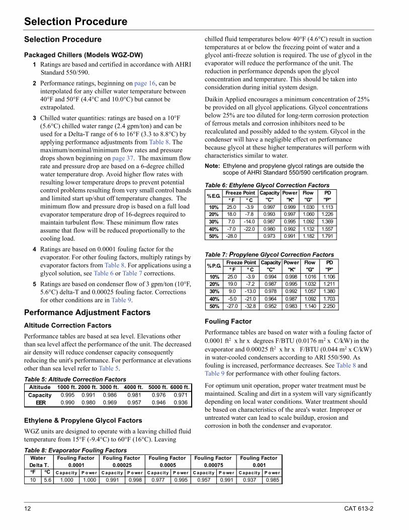
3 Chilled water quantities: ratings are based on a 10°F (5.6°C) chilled water range (2.4 gpm/ton) and can be used for a Delta-T range of 6 to 16°F (3.3 to 8.8°C) by applying performance adjustments from Table 8. The maximum/nominal/minimum flow rates and pressure drops shown beginning on page 37. The maximum flow rate and pressure drop are based on a 6-degree chilled water temperature drop. Avoid higher flow rates with resulting lower temperature drops to prevent potential control problems resulting from very small control bands and limited start up/shut off temperature changes. The minimum flow and pressure drop is based on a full load evaporator temperature drop of 16-degrees required to maintain turbulent flow. These minimum flow rates assume that flow will be reduced proportionally to the cooling load.
4 Ratings are based on 0.0001 fouling factor for the evaporator. For other fouling factors, multiply ratings by evaporator factors from Table 8. For applications using a glycol solution, see Table 6 or Table 7 corrections.
5 Ratings are based on condenser flow of 3 gpm/ton (10°F, 5.6°C) delta-T and 0.00025 fouling factor. Corrections for other conditions are in Table 9.
Performance Adjustment Factors
Altitude Correction Factors
Performance tables are based at sea level. Elevations other than sea level affect the performance of the unit. The decreased air density will reduce condenser capacity consequently reducing the unit's performance. For performance at elevations other than sea level refer to Table 5.
Table 5: Altitude Correction Factors
Ethylene & Propylene Glycol Factors
WGZ units are designed to operate with a leaving chilled fluid temperature from 15°F (-9.4°C) to 60°F (16°C). Leaving
chilled fluid temperatures below 40°F (4.6°C) result in suction temperatures at or below the freezing point of water and a glycol anti-freeze solution is required. The use of glycol in the evaporator will reduce the performance of the unit. The reduction in performance depends upon the glycol concentration and temperature. This should be taken into consideration during initial system design.
Daikin Applied encourages a minimum concentration of 25% be provided on all glycol applications. Glycol concentrations below 25% are too diluted for long-term corrosion protection of ferrous metals and corrosion inhibitors need to be recalculated and possibly added to the system. Glycol in the condenser will have a negligible effect on performance because glycol at these higher temperatures will perform with characteristics similar to water.
Note: Ethylene and propylene glycol ratings are outside the scope of AHRI Standard 550/590 certification program.
Table 6: Ethylene Glycol Correction Factors
Table 7: Propylene Glycol Correction Factors
Fouling Factor
Performance tables are based on water with a fouling factor of 0.0001 ft2 x hr x degrees F/BTU (0.0176 m2 x C/kW) in the evaporator and 0.00025 ft2 x hr x F/BTU (0.044 m2 x C/kW) in water-cooled condensers according to ARI 550/590. As fouling is increased, performance decreases. See Table 8 and Table 9 for performance with other fouling factors.
For optimum unit operation, proper water treatment must be maintained. Scaling and dirt in a system will vary significantly depending on local water conditions. Water treatment should be based on characteristics of the area's water. Improper or untreated water can lead to scale buildup, erosion and corrosion in both the condenser and evaporator.
Table 8: Evaporator Fouling Factors
Altitude 1000 ft. 2000 ft. 3000 ft. 4000 ft. 5000 ft. 6000 ft.
Capacity 0.995 0.991 0.986 0.981 0.976 0.971EER 0.990 0.980 0.969 0.957 0.946 0.936
° F ° C10% 25.0 -3.9 0.997 0.999 1.030 1.11320% 18.0 -7.8 0.993 0.997 1.060 1.226
30% 7.0 -14.0 0.987 0.995 1.092 1.369
40% -7.0 -22.0 0.980 0.992 1.132 1.55750% -28.0 0.973 0.991 1.182 1.791
Flow"G"
PD"P"
% E.G.Freeze Point Capacity
"C"Power
"K"
° F ° C10% 25.0 -3.9 0.994 0.998 1.016 1.10620% 19.0 -7.2 0.987 0.995 1.032 1.211
30% 9.0 -13.0 0.978 0.992 1.057 1.380
40% -5.0 -21.0 0.964 0.987 1.092 1.703
50% -27.0 -32.8 0.952 0.983 1.140 2.250
Flow"G"
PD"P"
% P.G.Freeze Point Capacity
"C"Power
"K"
oF oC C apacity P o wer C apacity P o wer C apacity P o wer C apacity P o wer C apacity P o wer
10 5.6 1.000 1.000 0.991 0.998 0.977 0.995 0.957 0.991 0.937 0.985
Water Delta T. 0.00075
Fouling Factor Fouling Factor 0.0005
Fouling Factor 0.001
Fouling Factor 0.0001 0.00025
Fouling Factor
CAT 613-2 13
Selection Procedure
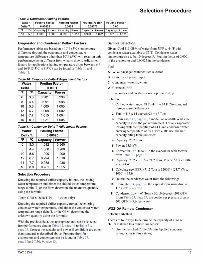
Table 9: Condenser Fouling Factors
Evaporator and Condenser Delta-T Factors
Performance tables are based on a 10°F (5°C) temperature difference through the evaporator and condenser. A temperature difference other than 10°F (5°C) will result in unit performance being different from what is shown. Adjustment factors for applications having temperature drops between 6 F and 16°F (3.3°C to 8.9°C) can be found in Table 10 and Table 11.
Table 10: Evaporator Delta-T Adjustment Factors
Table 11: Condenser Delta-T Adjustment Factors
Selection Procedure
Knowing the required chiller capacity in tons, the leaving water temperature and either the chilled water temperature range (Delta T) or the flow, determine the unknown quantity using the formula:
Tons= GPM x Delta T/24 (water only)
Knowing the required chiller capacity (tons), the entering condenser water temperature, and either the condenser water temperature range-delta T, or the GPM, determine the unknown quantity using the formula:
With the previous data, the appropriate unit can be selected fromperformance data in Table 12, page 16 to Table 31, page 35. Correct the capacity and power if conditions are other than standard as described above. Pressure drop for evaporators and condensers can be found in Table 33, page 37and Table 9, page 13.
Sample Selection
Given: Cool 115 GPM of water from 58°F to 44°F with condenser water available at 85°F. Condenser water temperature rise to be 10 degrees F. Fouling factor of 0.0001 in the evaporator and 0.00025 in the condenser.
Find:
A WGZ packaged water chiller selection
B Compressor power input
C Condenser water flow rate
D Corrected EER
E Evaporator and condenser water pressure drop
Solution:
1 Chilled water range: 58 F - 44 F = 14 F (Nonstandard Temperature Difference).
2 Tons = 115 x 14 degrees/24 = 67 Tons
3 From Table 12, page 16, a model WGZ-070DW has the capacity to meet the job requirement. For an evaporator leaving water temperature of 44 F and condenser water entering temperature of 85 F with a 10° rise, the unit capacity rating table indicates:
4 Capacity: 70.2 Tons
5 Power: 53.3 kW
6 Correct for 14° Delta-T in the evaporator with factors from Table 10, page 13.
7 Capacity: 70.2 x 1.015 = 71.2 Tons, Power: 53.3 x 1.004 = 53.7 kW
8 Calculate new EER: (71.2 Tons x 12000) / (53.7 kW x 1000) = 15.9
9 Determine condenser water from the following:
10 FromTable 34, page 38, the vaporator pressure drop at 115 GPM is 6.2 feet.
11 Condenser flow = 67 Tons x 30/10 degrees=201 GPM. From Table 33, page 37, the condenser pressure drop at 201 GPM is 9.6 feet water
WGZ-DA Remote Condenser
Selection Method
There are four ways to determine the capacity of a WGZ chiller matched to a remote condenser:
1 Use the matched Chiller/Daikin Applied condenser rating tables in this catalog.
oF oC C apacity P o wer C apacity P o wer C apacity P o wer C apacity P o wer
10 5.6 1.000 1.000 0.995 1.010 0.990 1.022 0.981 1.035
WaterDelta T.
Fouling Factor 0.001
Fouling Factor 0.00075
Fouling Factor 0.00025 0.0005
Fouling Factor
oF oC Capacity Power
6 3.3 0.981 0.996
8 4.4 0.991 0.99810 5.6 1.000 1.00012 6.7 1.008 1.00214 7.7 1.015 1.00416 8.9 1.021 1.005
Water Delta T.
Fouling Factor 0.0001
oF oC Capacity Power
6 3.3 1.012 0.960
8 4.4 1.006 0.98010 5.6 1.000 1.00012 6.7 0.994 1.01814 7.7 0.988 1.03616 8.9 0.981 1.055
Delta T. 0.00025Water Fouling Factor

14 CAT 613-2
Selection Procedure
2 Contact the Daikin Applied sales office for a computerized selection using a Daikin Applied condenser.
3 Calculate the performance interpolating chiller and any remote condenser capacity.
4 Plot the chiller heat rejection and any remote condenser capacity to find the balance point.
Examples of methods 1, 3 and 4 follow.
Method 1, Matched Chiller/Condenser Rating
Table 32, page 36 gives performance data for WGZ models matched with several sizes of Daikin Applied air-cooled condensers (1140 rpm fans). The ratings points are limited due to the large number of chiller/condenser combinations. If particular job conditions do not match the table rating points, do not extrapolate. Use the table selections as a guide to make specific selections at the job conditions.
The performance shown is based on a 5 psi discharge line pressure drop. In many cases there are one or more larger condensers that will also match the chiller. They are usually in the realm of diminishing return on investment but can be selected manually if desired.
Dual row condensers are used since they match up easily with the two circuits on the WGZ units. Splitting the coil of a single row unit results in an uncontrollable head pressure situation.
Two single row condenser can be used and placed end-to-end for a long narrow condenser site.
The power (PWR) and efficiency (EER) shown include the condenser fan power. Selections are at sea level altitude, 14 fpi, 10-degree F delta-T and 0.0001 fouling factor. See Table 5, page 12 for altitude correction. Contact the local Daikin Applied sales office for other non-standard selections.
Method 2, Table Interpolation
The performance of the WGZ-DA chillers is listed by LWT (leaving chilled water temperature) and by Discharge Temperature. Unit Tons, Power, and THR (Total Heat Rejection) are givenfor each performance point. This data can then be used to select any condenser. Use Catalog A-C Cond for Daikin ACL, ACX, ACH air-cooled condensers. It is important to note that most condensers are rated on saturated condensing temperature and Daikin Applied chillers are rated on saturated discharge temperature. Therefore it is necessary to account for the discharge piping line loss. Most designs are based on a pressure drop equivalent to two-degrees F. Unless otherwise stated, the condenser should therefore be selected with a condensing temperature two-degrees F less than the compressor discharge temperature.
1 Ratings can be interpolated for any chiller water temperature between 40°F and 50°F (4.4°C and 10°C) but cannot be extrapolated (contact the local Daikin Applied sales office for ratings outside this range).
2 Chilled water quantities. Ratings are based on a 10°F chilled-water range and are applicable from a minimum of 6°F to a maximum of 16°F differential between entering and leaving chilled water temperatures.
3 Ratings are based on 0.0001 fouling factor for the evaporator. For other fouling factors, multiply ratings by cooler factors from Table 8, page 12 or Table 9, page 13. For applications using a glycol solution, see Table 6, page 12 or Table 7, page 12.
4 Ratings are based on sea level altitude (corrected from Table 5, page 12) and 5 psi discharge and liquid line pressure drop. Consult the Daikin Applied sales office for other conditions.
EFFICIENCY NOTE: Generally, larger condensers will provide better system efficiency. However, a point of diminishing return can often be reached where the added condenser fans consume more power than is saved by the chiller operating at a lower discharge pressure. The system EER may actually go down.
Selection Procedure
The following selection procedure can be used or selections can be picked from matched WGZ and Daikin Applied air-cooled condenser selections found in Table 32, page 36.
Normally, the required chiller capacity in tons, the entering and leaving chilled water temperature, flow, and the design outdoor air temperature are known. Determine any unknown quantity using the formula:
Tons = gpm x Delta-T / 24 (water only)
Capacity data is based on:
"Leaving chilled water temperatures from 40ºF to 50ºF (4.4ºC to 10ºC) with a 10-degree F Delta-T. Selections can be interpolated between these leaving temperatures but not extrapolated. Correction factors for Delta-Ts other than 10° are in Table 10, page 13. Exceeding the Delta-T range of 6 to 16 degrees F will cause problems controlling unit unloading.
"Condensing temperatures (CT) from 105ºF to 125ºF (40ºC to 55ºC).
"Total Heat Rejection (THR) is used to select the condenser, whether it is a dry, air-cooled or evaporative-condenser type.
Several different size condensers can usually be matched to any given WGZ-DA unit depending on the condensing temperature that typically ranges from 20 to 30°F above the outdoor temperature. Increasing condensing temperatures will reduce the chiller capacity, increase its power, reduce efficiency, but will result in a smaller, lower cost condenser being required.
Normally a WGZ-DA is selected to meet or exceed the required cooling capacity at some discharge temperature, and a condenser then selected with sufficient capacity to handle the heat rejection with the selected temperature difference (TD,
CAT 613-2 15
Selection Procedure
difference between design outdoor dry bulb temperature and condensing temperature).
Sample Selections
Given: Required capacity of 50 tons, cooling 120 gpm of water from 54ºF to 44ºF with 95 F design dry bulb temperature, sea level altitude, 5 psi (2°F) discharge and liquid line pressure drop and evaporator fouling factor of 0.0001.
Find:
1 WGZ water chiller and a model ACH condenser selection
2 Compressor power input, chilled water pressure drop
Solution:
1 From Table 20, page 24, two WGZ selections are possible:
a WGZ 050D at 105° F CT; 52.4 tons, 42.4 kW, 773.6 mbh THR, 0.848 kW/ton (calculated)
b WGZ 055D at 125° F CT; 50.6 tons, 56.9 kW, 801.8 mbh THR, 1.14 kW/ton (calculated)
Note that the condensing temperature has significant influence on the chiller efficiency. Progressing from a to b above will require smaller condensers, offset by larger, more expensive chillers and lower efficiency. The WGZ 050 selection with a 10-degree approach (disregarding line loss) will result in a large jump of more four condenser sizes.
2 For this example, a Daikin Model ACH air-cooled condenser will be selected using selection procedures and data contained in Catalog A-C Cond. A model ACH AD (double circuit, two rows of fans, 1140 rpm fan speed) will be used.
For the WGZ055D with a 30-degree temperature differential, (125°F - 95°F) a Model ACH050AD with 14 fpi will do the
service with a capacity of 978.000 mbh. If a high efficiency selection is desired, it usually most productive to select (when possible) a WGZ with a low condensing temperature as the power savings on the chiller will exceed the additional fan horsepower required for the larger condenser.
An economic decision must often be made between low first cost and low operating cost.
Method 4, Plotting
A more accurate solution can be achieved by plotting the capacity of the chiller and the condenser as a function of the TD and observing the curves intersection that is the system balance point. An example is shown in the following "Selection Example" section.
Graphical solutions can also be used as shown in the following typical example:
a Take the WGZ heat rejection values at two temperatures differences and connecting them, drawing a heat rejection curve.
b Plot and connect the air-cooled condenser capacity at two different temperature differences.
c The intersection of the curves is the full load balance point for the chiller/condenser combination.
d Add 2 degrees (estimated) to chiller discharge temperature to account for line loss and extrapolate the WGZ chiller capacity at that point. This will give accurate performance data for the combination.
AHRI Certification
Performance on all 60Hz standard packaged models is certified per AHRI standard 550/590. Chillers with optional remote evaporators or chillers with glycol applications are outside the scope of the AHRI rating program. Ratings in bold are at AHRI standard conditions.

16 CAT 613-2
Performance DataPerformance Data
Table 12: 60 Hz (Packaged Chiller) Full Load Performance Data (IP)
Unit PWR Unit Unit PWR Unit Unit PWR Unit Unit PWR Unit Unit PWR Unit
Tons kWi EER Tons kWi EER Tons kWi EER Tons kWi EER Tons kWi EER
40 29.2 20.9 16.8 28.6 21.9 15.7 28.1 23.0 14.6 27.4 24.2 13.6 26.7 25.5 12.6
42 30.2 21.1 17.2 29.6 22.1 16.1 29.0 23.2 15.3 28.3 24.4 13.9 27.6 25.6 13.0
44 31.2 21.3 17.6 30.6 22.2 16.6 30.0 23.4 15.4 29.2 24.5 14.3 28.5 25.7 13.4
46 32.3 21.4 18.1 31.7 22.4 17.0 31.0 23.5 15.8 30.2 24.6 14.8 29.6 25.9 13.748 33.3 21.6 18.5 32.7 22.5 17.4 32.0 23.6 16.3 31.3 24.7 15.2 30.6 26.0 14.150 34.7 21.8 19.0 33.8 22.7 17.9 33.1 23.7 16.8 32.3 24.9 15.6 31.7 26.2 14.5
40 33.7 23.1 17.5 33.0 24.1 16.4 32.4 25.4 15.3 31.6 26.7 14.2 30.8 28.1 13.142 34.8 23.3 18.0 34.2 24.3 16.9 33.5 25.6 16.0 32.6 26.9 14.6 31.8 28.2 13.644 36.0 23.5 18.5 35.3 24.5 17.3 34.6 25.8 16.1 33.6 27.0 15.0 32.9 28.3 14.046 37.2 23.6 18.9 36.5 24.7 17.8 35.7 25.9 16.6 34.8 27.1 15.4 34.1 28.5 14.448 38.4 23.8 19.4 37.7 24.8 18.2 36.9 26.0 17.0 36.1 27.2 15.9 35.3 28.7 14.850 40.0 24.1 19.9 39.0 25.0 18.7 38.2 26.1 17.5 37.3 27.4 16.3 36.6 28.9 15.2
40 39.6 27.1 17.5 38.8 28.4 16.4 38.1 29.8 15.3 37.1 31.4 14.2 36.2 33.0 13.142 41.0 27.3 18.0 40.2 28.6 16.9 39.4 30.1 16.0 38.3 31.5 14.6 37.4 33.1 13.644 42.4 27.5 18.5 41.6 28.8 17.3 40.7 30.3 16.1 39.6 31.7 15.0 38.7 33.2 14.046 43.8 27.8 18.9 43.0 29.0 17.8 42.0 30.5 16.6 41.0 31.8 15.4 40.1 33.5 14.448 45.2 28.0 19.4 44.4 29.1 18.2 43.4 30.6 17.0 42.4 32.0 15.9 41.6 33.7 14.850 47.1 28.3 19.9 45.8 29.3 18.7 44.9 30.7 17.5 43.9 32.2 16.3 43.0 34.0 15.2
40 44.3 30.9 17.2 43.4 32.3 16.1 42.5 33.9 15.0 41.5 35.7 13.9 40.4 37.6 12.942 45.8 31.1 17.6 45.0 32.5 16.5 44.0 34.2 15.7 42.9 35.9 14.3 41.9 37.7 13.344 47.4 31.4 18.1 46.5 32.7 17.0 45.5 34.5 15.8 44.2 36.1 14.7 43.3 37.8 13.746 49.0 31.6 18.5 48.0 33.0 17.4 47.0 34.7 16.2 45.8 36.2 15.2 44.9 38.1 14.148 50.6 31.9 19.0 49.6 33.2 17.9 48.5 34.8 16.7 47.4 36.4 15.6 46.5 38.4 14.550 52.6 32.2 19.5 51.2 33.4 18.4 50.2 34.9 17.2 49.0 36.6 16.0 48.1 38.7 14.9
40 50.1 35.4 17.0 49.0 37.0 15.9 48.1 38.9 14.8 46.9 40.9 13.7 45.7 43.0 12.742 51.8 35.6 17.4 50.8 37.2 16.3 49.7 39.2 15.5 48.4 41.1 14.1 47.3 43.2 13.144 53.5 35.9 17.9 52.5 37.5 16.8 51.4 39.5 15.6 50.0 41.3 14.5 48.9 43.3 13.546 55.3 36.2 18.3 54.3 37.8 17.2 53.1 39.7 16.0 51.8 41.5 15.0 50.7 43.6 13.948 57.1 36.5 18.8 56.0 38.0 17.7 54.8 39.9 16.5 53.6 41.7 15.4 52.5 44.0 14.350 59.5 36.9 19.3 57.9 38.2 18.1 56.7 40.0 17.0 55.4 41.9 15.8 54.3 44.3 14.7
40 54.9 38.6 17.1 53.8 40.3 16.0 52.7 42.4 14.9 51.4 44.7 13.8 50.1 46.9 12.842 56.8 38.9 17.5 55.7 40.6 16.4 54.5 42.8 15.6 53.1 44.9 14.2 51.9 47.1 13.244 58.7 39.2 18.0 57.6 40.9 16.9 56.4 43.1 15.7 54.8 45.0 14.6 53.6 47.3 13.646 60.7 39.5 18.4 59.6 41.2 17.3 58.3 43.3 16.1 56.8 45.3 15.1 55.6 47.6 14.048 62.7 39.8 18.9 61.5 41.5 17.8 60.2 43.5 16.6 58.8 45.5 15.5 57.6 48.0 14.450 65.3 40.2 19.4 63.5 41.7 18.3 62.2 43.7 17.1 60.8 45.8 15.9 59.6 48.3 14.8
40 58.9 41.6 17.0 57.7 43.5 15.9 56.6 45.8 14.8 55.2 48.2 13.7 53.8 50.6 12.742 60.9 41.9 17.4 59.8 43.8 16.3 58.5 46.1 15.5 57.0 48.4 14.1 55.7 50.8 13.144 63.0 42.3 17.9 61.8 44.1 16.8 60.5 46.5 15.6 58.8 48.6 14.5 57.5 51.0 13.546 65.1 42.6 18.3 63.9 44.5 17.2 62.5 46.7 16.0 60.9 48.8 15.0 59.7 51.4 13.948 67.2 43.0 18.8 65.9 44.7 17.7 64.6 46.9 16.5 63.0 49.1 15.4 61.8 51.8 14.350 70.0 43.4 19.3 68.1 45.0 18.1 66.7 47.1 17.0 65.2 49.4 15.8 63.9 52.1 14.7
40 68.4 47.7 17.2 67.0 49.9 16.1 65.6 52.4 15.0 64.0 55.2 13.9 62.4 58.0 12.942 70.7 48.1 17.6 69.4 50.3 16.5 67.9 52.9 15.7 66.1 55.5 14.3 64.6 58.3 13.344 73.1 48.4 18.1 71.7 50.6 17.0 70.2 53.3 15.8 68.2 55.7 14.7 66.8 58.5 13.746 75.5 48.8 18.5 74.1 51.0 17.4 72.5 53.6 16.2 70.7 56.0 15.2 69.2 58.9 14.148 78.0 49.2 19.0 76.5 51.3 17.9 74.9 53.8 16.7 73.1 56.3 15.6 71.7 59.3 14.550 81.2 49.7 19.5 79.0 51.6 18.4 77.4 54.0 17.2 75.7 56.6 16.0 74.2 59.7 14.9
60
60
60
60
60
035
030
Unit Size
Hz
60
070 60
040
045
050
060
055
Evap.LWT(°F)
60
Entering Condenser Water Temperature (°F)
75°F 80°F 85°F 90°F 95°F
CAT 613-2 17
Performance Data
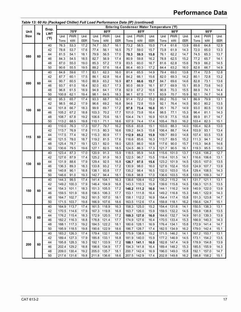
Table 13: 60 Hz (Packaged Chiller) Full Load Performance Data (IP) (continued)
Unit PWR Unit Unit PWR Unit Unit PWR Unit Unit PWR Unit Unit PWR UnitTons kWi EER Tons kWi EER Tons kWi EER Tons kWi EER Tons kWi EER
40 76.3 53.3 17.2 74.7 55.7 16.1 73.2 58.5 15.0 71.4 61.6 13.9 69.6 64.8 12.942 78.8 53.7 17.6 77.4 56.1 16.5 75.7 59.0 15.7 73.8 61.9 14.3 72.0 65.0 13.344 81.5 54.1 18.1 79.9 56.5 17.0 78.3 59.5 15.8 76.1 62.2 14.7 74.5 65.3 13.746 84.3 54.5 18.5 82.7 56.9 17.4 80.9 59.8 16.2 78.8 62.5 15.2 77.2 65.7 14.148 87.0 55.0 19.0 85.3 57.2 17.9 83.5 60.0 16.7 81.6 62.8 15.6 79.9 66.2 14.550 90.6 55.5 19.5 88.2 57.6 18.4 86.4 60.3 17.2 84.4 63.2 16.0 82.8 66.7 14.9
40 84.8 59.6 17.1 83.1 62.3 16.0 81.4 65.5 14.9 79.4 69.0 13.8 77.4 72.5 12.842 87.7 60.1 17.5 86.1 62.8 16.4 84.2 66.1 15.6 82.0 69.3 14.2 80.1 72.8 13.244 90.7 60.5 18.0 88.9 63.2 16.9 87.1 66.6 15.7 84.7 69.6 14.6 82.8 73.1 13.646 93.7 61.0 18.4 92.0 63.7 17.3 90.0 66.9 16.1 87.7 69.9 15.1 85.9 73.6 14.048 96.8 61.5 18.9 94.9 64.1 17.8 92.9 67.2 16.6 90.8 70.3 15.5 88.9 74.1 14.450 100.8 62.1 19.4 98.1 64.5 18.3 96.1 67.5 17.1 93.9 70.7 15.9 92.1 74.7 14.8
40 95.3 65.7 17.4 93.3 68.7 16.3 91.4 72.2 15.2 89.2 76.0 14.1 86.9 79.9 13.142 98.5 66.2 17.9 96.6 69.2 16.8 94.6 72.8 15.9 92.1 76.4 14.5 90.0 80.2 13.544 101.8 66.7 18.3 99.9 69.7 17.2 97.8 73.4 16.0 95.1 76.7 14.9 93.0 80.5 13.946 105.2 67.2 18.8 103.3 70.2 17.7 101.0 73.8 16.4 98.5 77.1 15.3 96.4 81.1 14.348 108.7 67.8 19.2 106.6 70.6 18.1 104.4 74.1 16.9 101.9 77.5 15.8 99.9 81.7 14.750 113.2 68.5 19.8 110.1 71.1 18.6 107.9 74.4 17.4 105.4 78.0 16.2 103.4 82.3 15.1
40 110.0 76.3 17.3 107.7 79.7 16.2 105.6 83.8 15.1 103.0 88.3 14.0 100.4 92.8 13.042 113.7 76.9 17.8 111.5 80.3 16.6 109.2 84.5 15.8 106.4 88.7 14.4 103.9 93.1 13.444 117.5 77.4 18.2 115.3 80.9 17.1 112.9 85.2 15.9 109.7 89.0 14.8 107.4 93.5 13.846 121.5 78.0 18.7 119.2 81.5 17.6 116.6 85.6 16.3 113.7 89.5 15.2 111.3 94.1 14.248 125.4 78.7 19.1 123.1 82.0 18.0 120.5 86.0 16.8 117.6 90.0 15.7 115.3 94.8 14.650 130.6 79.5 19.6 127.1 82.5 18.5 124.5 86.3 17.3 121.7 90.5 16.1 119.3 95.5 15.0
40 123.4 87.3 17.0 120.9 91.3 15.9 118.5 95.9 14.8 115.6 101.0 13.7 112.6 106.2 12.742 127.6 87.9 17.4 125.2 91.9 16.3 122.5 96.7 15.5 119.4 101.5 14.1 116.6 106.6 13.144 131.9 88.6 17.9 129.4 92.5 16.8 126.7 97.5 15.6 123.2 101.9 14.5 120.5 107.0 13.546 136.3 89.3 18.3 133.8 93.2 17.2 130.9 98.0 16.0 127.6 102.4 15.0 124.9 107.7 13.948 140.8 90.1 18.8 138.1 93.8 17.7 135.2 98.4 16.5 132.0 103.0 15.4 129.4 108.5 14.350 146.6 91.0 19.3 142.7 94.4 18.1 139.8 98.8 17.0 136.6 103.5 15.8 133.9 109.3 14.7
40 144.3 99.5 17.4 141.4 104.1 16.3 138.6 109.4 15.2 135.2 115.2 14.1 131.7 121.1 13.142 149.2 100.3 17.9 146.4 104.9 16.8 143.3 110.3 15.9 139.6 115.8 14.5 136.3 121.5 13.544 154.3 101.1 18.3 151.3 105.5 17.2 148.2 111.2 16.0 144.1 116.2 14.9 140.9 122.0 13.946 159.5 101.9 18.8 156.5 106.3 17.7 153.1 111.8 16.4 149.2 116.8 15.3 146.1 122.9 14.348 164.7 102.7 19.2 161.5 107.0 18.1 158.1 112.2 16.9 154.4 117.4 15.8 151.3 123.8 14.750 171.5 103.7 19.8 166.9 107.6 18.6 163.5 112.6 17.4 159.8 118.1 16.2 156.6 124.7 15.1
40 164.9 113.7 17.4 161.5 118.9 16.3 158.3 125.0 15.2 154.4 131.6 14.1 150.5 138.3 13.142 170.5 114.6 17.9 167.3 119.8 16.8 163.7 126.0 15.9 159.5 132.2 14.5 155.8 138.8 13.544 176.2 115.4 18.3 172.9 120.5 17.2 169.3 127.0 16.0 164.6 132.7 14.9 161.0 139.3 13.946 182.2 116.3 18.8 178.8 121.4 17.7 174.9 127.6 16.4 170.5 133.4 15.3 166.9 140.3 14.348 188.1 117.3 19.2 184.5 122.2 18.1 180.6 128.1 16.9 176.4 134.1 15.8 172.9 141.4 14.750 195.9 118.5 19.8 190.6 122.9 18.6 186.7 128.7 17.4 182.5 134.9 16.2 179.0 142.4 15.1
40 183.2 126.3 17.4 179.4 132.1 16.3 175.9 138.8 15.2 171.5 146.2 14.1 167.2 153.7 13.142 189.4 127.3 17.9 185.8 133.1 16.8 181.9 140.0 15.9 177.2 146.9 14.5 173.1 154.2 13.544 195.8 128.3 18.3 192.1 133.9 17.2 188.1 141.1 16.0 182.8 147.4 14.9 178.9 154.8 13.946 202.4 129.2 18.8 198.6 134.9 17.7 194.3 141.8 16.4 189.4 148.2 15.3 185.5 155.9 14.348 209.0 130.4 19.2 205.0 135.7 18.1 200.7 142.4 16.9 196.0 149.0 15.8 192.1 157.0 14.750 217.6 131.6 19.8 211.8 136.6 18.6 207.5 142.9 17.4 202.8 149.8 16.2 198.8 158.2 15.1
115
130
170
200
150
60
Hz
60
60
60
60
60
60
60
080
100
090
Unit Size
Evap.LWT(°F)
Entering Condenser Water Temperature (°F)
75°F 80°F 85°F 90°F 95°F
18 CAT 613-2
Performance Data
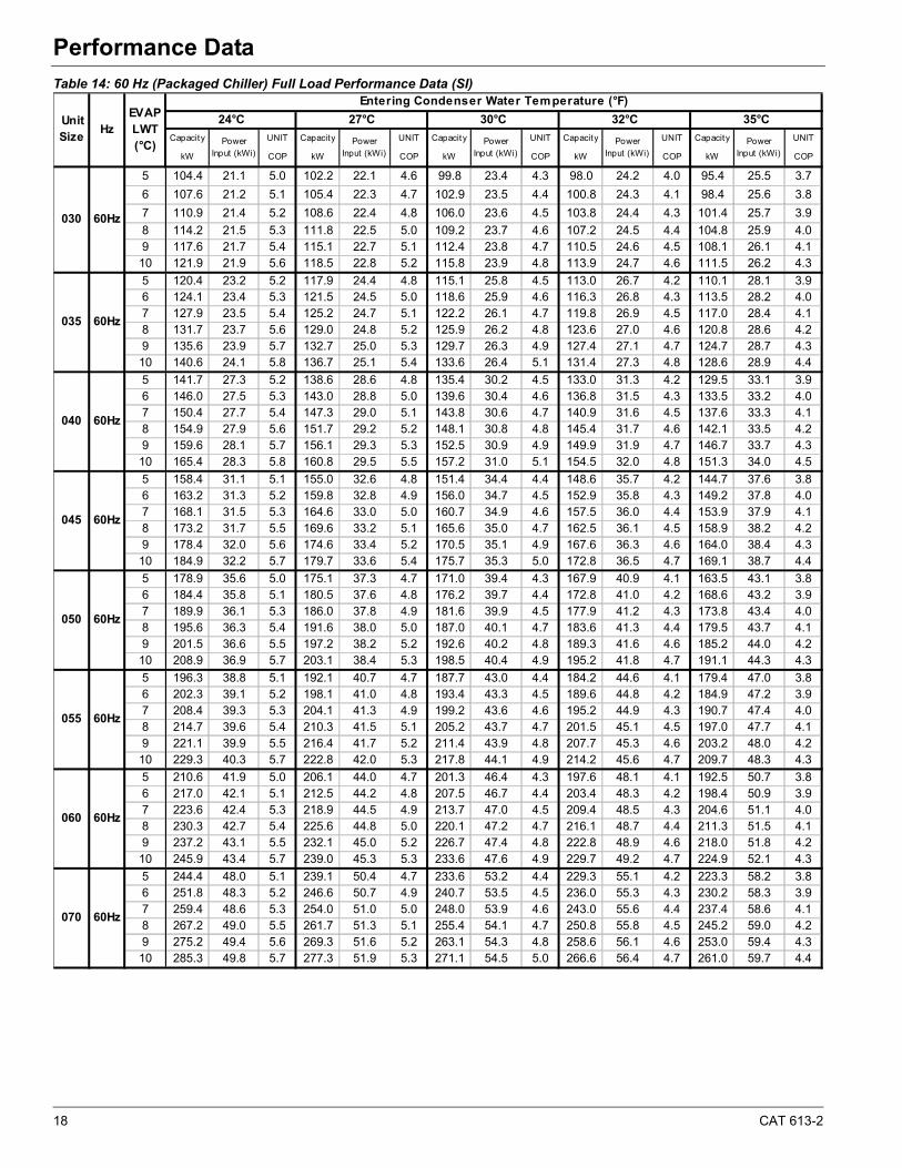
Table 14: 60 Hz (Packaged Chiller) Full Load Performance Data (SI)
Capacity UNIT Capacity UNIT Capacity UNIT Capacity UNIT Capacity UNIT
kW COP kW COP kW COP kW COP kW COP
5 104.4 21.1 5.0 102.2 22.1 4.6 99.8 23.4 4.3 98.0 24.2 4.0 95.4 25.5 3.7
6 107.6 21.2 5.1 105.4 22.3 4.7 102.9 23.5 4.4 100.8 24.3 4.1 98.4 25.6 3.8
7 110.9 21.4 5.2 108.6 22.4 4.8 106.0 23.6 4.5 103.8 24.4 4.3 101.4 25.7 3.9
8 114.2 21.5 5.3 111.8 22.5 5.0 109.2 23.7 4.6 107.2 24.5 4.4 104.8 25.9 4.09 117.6 21.7 5.4 115.1 22.7 5.1 112.4 23.8 4.7 110.5 24.6 4.5 108.1 26.1 4.110 121.9 21.9 5.6 118.5 22.8 5.2 115.8 23.9 4.8 113.9 24.7 4.6 111.5 26.2 4.3
5 120.4 23.2 5.2 117.9 24.4 4.8 115.1 25.8 4.5 113.0 26.7 4.2 110.1 28.1 3.96 124.1 23.4 5.3 121.5 24.5 5.0 118.6 25.9 4.6 116.3 26.8 4.3 113.5 28.2 4.07 127.9 23.5 5.4 125.2 24.7 5.1 122.2 26.1 4.7 119.8 26.9 4.5 117.0 28.4 4.18 131.7 23.7 5.6 129.0 24.8 5.2 125.9 26.2 4.8 123.6 27.0 4.6 120.8 28.6 4.29 135.6 23.9 5.7 132.7 25.0 5.3 129.7 26.3 4.9 127.4 27.1 4.7 124.7 28.7 4.310 140.6 24.1 5.8 136.7 25.1 5.4 133.6 26.4 5.1 131.4 27.3 4.8 128.6 28.9 4.4
5 141.7 27.3 5.2 138.6 28.6 4.8 135.4 30.2 4.5 133.0 31.3 4.2 129.5 33.1 3.96 146.0 27.5 5.3 143.0 28.8 5.0 139.6 30.4 4.6 136.8 31.5 4.3 133.5 33.2 4.07 150.4 27.7 5.4 147.3 29.0 5.1 143.8 30.6 4.7 140.9 31.6 4.5 137.6 33.3 4.18 154.9 27.9 5.6 151.7 29.2 5.2 148.1 30.8 4.8 145.4 31.7 4.6 142.1 33.5 4.29 159.6 28.1 5.7 156.1 29.3 5.3 152.5 30.9 4.9 149.9 31.9 4.7 146.7 33.7 4.310 165.4 28.3 5.8 160.8 29.5 5.5 157.2 31.0 5.1 154.5 32.0 4.8 151.3 34.0 4.5
5 158.4 31.1 5.1 155.0 32.6 4.8 151.4 34.4 4.4 148.6 35.7 4.2 144.7 37.6 3.86 163.2 31.3 5.2 159.8 32.8 4.9 156.0 34.7 4.5 152.9 35.8 4.3 149.2 37.8 4.07 168.1 31.5 5.3 164.6 33.0 5.0 160.7 34.9 4.6 157.5 36.0 4.4 153.9 37.9 4.18 173.2 31.7 5.5 169.6 33.2 5.1 165.6 35.0 4.7 162.5 36.1 4.5 158.9 38.2 4.29 178.4 32.0 5.6 174.6 33.4 5.2 170.5 35.1 4.9 167.6 36.3 4.6 164.0 38.4 4.310 184.9 32.2 5.7 179.7 33.6 5.4 175.7 35.3 5.0 172.8 36.5 4.7 169.1 38.7 4.4
5 178.9 35.6 5.0 175.1 37.3 4.7 171.0 39.4 4.3 167.9 40.9 4.1 163.5 43.1 3.86 184.4 35.8 5.1 180.5 37.6 4.8 176.2 39.7 4.4 172.8 41.0 4.2 168.6 43.2 3.97 189.9 36.1 5.3 186.0 37.8 4.9 181.6 39.9 4.5 177.9 41.2 4.3 173.8 43.4 4.08 195.6 36.3 5.4 191.6 38.0 5.0 187.0 40.1 4.7 183.6 41.3 4.4 179.5 43.7 4.19 201.5 36.6 5.5 197.2 38.2 5.2 192.6 40.2 4.8 189.3 41.6 4.6 185.2 44.0 4.210 208.9 36.9 5.7 203.1 38.4 5.3 198.5 40.4 4.9 195.2 41.8 4.7 191.1 44.3 4.3
5 196.3 38.8 5.1 192.1 40.7 4.7 187.7 43.0 4.4 184.2 44.6 4.1 179.4 47.0 3.86 202.3 39.1 5.2 198.1 41.0 4.8 193.4 43.3 4.5 189.6 44.8 4.2 184.9 47.2 3.97 208.4 39.3 5.3 204.1 41.3 4.9 199.2 43.6 4.6 195.2 44.9 4.3 190.7 47.4 4.08 214.7 39.6 5.4 210.3 41.5 5.1 205.2 43.7 4.7 201.5 45.1 4.5 197.0 47.7 4.19 221.1 39.9 5.5 216.4 41.7 5.2 211.4 43.9 4.8 207.7 45.3 4.6 203.2 48.0 4.210 229.3 40.3 5.7 222.8 42.0 5.3 217.8 44.1 4.9 214.2 45.6 4.7 209.7 48.3 4.3
5 210.6 41.9 5.0 206.1 44.0 4.7 201.3 46.4 4.3 197.6 48.1 4.1 192.5 50.7 3.86 217.0 42.1 5.1 212.5 44.2 4.8 207.5 46.7 4.4 203.4 48.3 4.2 198.4 50.9 3.97 223.6 42.4 5.3 218.9 44.5 4.9 213.7 47.0 4.5 209.4 48.5 4.3 204.6 51.1 4.08 230.3 42.7 5.4 225.6 44.8 5.0 220.1 47.2 4.7 216.1 48.7 4.4 211.3 51.5 4.19 237.2 43.1 5.5 232.1 45.0 5.2 226.7 47.4 4.8 222.8 48.9 4.6 218.0 51.8 4.210 245.9 43.4 5.7 239.0 45.3 5.3 233.6 47.6 4.9 229.7 49.2 4.7 224.9 52.1 4.3
5 244.4 48.0 5.1 239.1 50.4 4.7 233.6 53.2 4.4 229.3 55.1 4.2 223.3 58.2 3.86 251.8 48.3 5.2 246.6 50.7 4.9 240.7 53.5 4.5 236.0 55.3 4.3 230.2 58.3 3.97 259.4 48.6 5.3 254.0 51.0 5.0 248.0 53.9 4.6 243.0 55.6 4.4 237.4 58.6 4.18 267.2 49.0 5.5 261.7 51.3 5.1 255.4 54.1 4.7 250.8 55.8 4.5 245.2 59.0 4.29 275.2 49.4 5.6 269.3 51.6 5.2 263.1 54.3 4.8 258.6 56.1 4.6 253.0 59.4 4.310 285.3 49.8 5.7 277.3 51.9 5.3 271.1 54.5 5.0 266.6 56.4 4.7 261.0 59.7 4.4
070 60Hz
35°C
Power Input (kWi)
030 60Hz
035 60Hz
055 60Hz
Unit Size
HzEVAP LWT (°C)
Entering Condenser Water Temperature (°F)
24°C 27°C 30°C 32°C
040 60Hz
045 60Hz
060 60Hz
050 60Hz
Power Input (kWi)
Power Input (kWi)
Power Input (kWi)
Power Input (kWi)
CAT 613-2 19
Performance Data
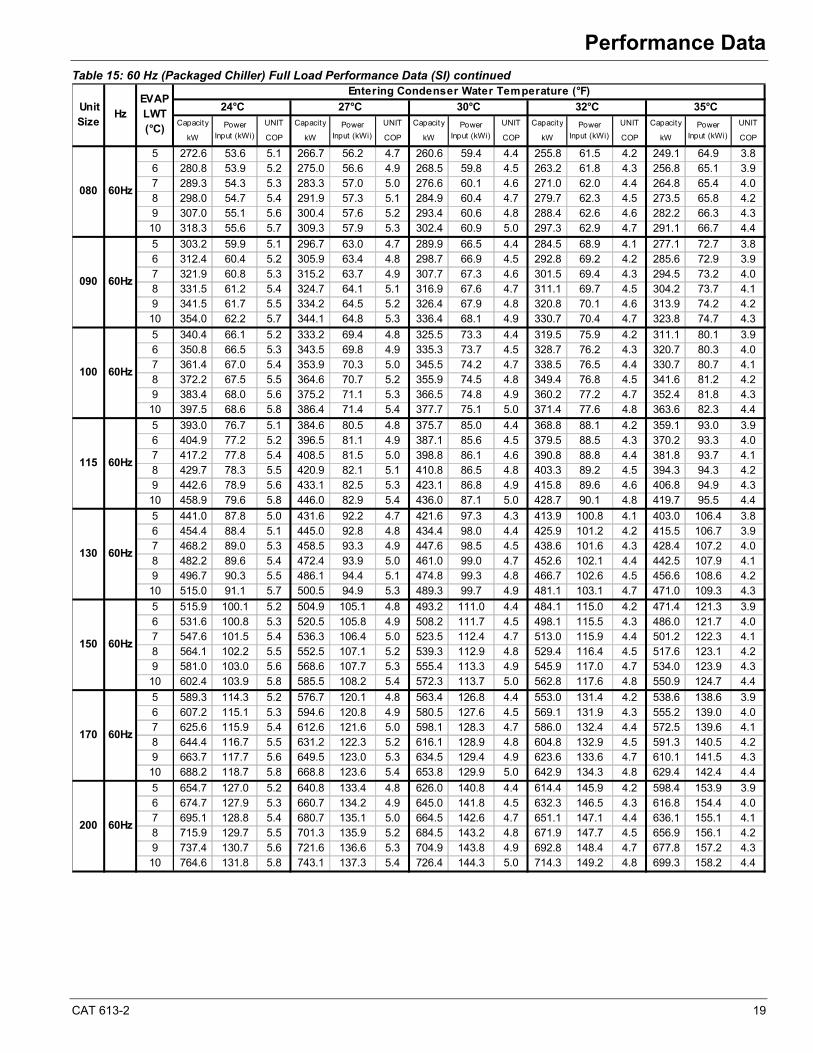
Table 15: 60 Hz (Packaged Chiller) Full Load Performance Data (SI) continued
Capacity UNIT Capacity UNIT Capacity UNIT Capacity UNIT Capacity UNIT
kW COP kW COP kW COP kW COP kW COP
5 272.6 53.6 5.1 266.7 56.2 4.7 260.6 59.4 4.4 255.8 61.5 4.2 249.1 64.9 3.86 280.8 53.9 5.2 275.0 56.6 4.9 268.5 59.8 4.5 263.2 61.8 4.3 256.8 65.1 3.97 289.3 54.3 5.3 283.3 57.0 5.0 276.6 60.1 4.6 271.0 62.0 4.4 264.8 65.4 4.08 298.0 54.7 5.4 291.9 57.3 5.1 284.9 60.4 4.7 279.7 62.3 4.5 273.5 65.8 4.29 307.0 55.1 5.6 300.4 57.6 5.2 293.4 60.6 4.8 288.4 62.6 4.6 282.2 66.3 4.310 318.3 55.6 5.7 309.3 57.9 5.3 302.4 60.9 5.0 297.3 62.9 4.7 291.1 66.7 4.4
5 303.2 59.9 5.1 296.7 63.0 4.7 289.9 66.5 4.4 284.5 68.9 4.1 277.1 72.7 3.86 312.4 60.4 5.2 305.9 63.4 4.8 298.7 66.9 4.5 292.8 69.2 4.2 285.6 72.9 3.97 321.9 60.8 5.3 315.2 63.7 4.9 307.7 67.3 4.6 301.5 69.4 4.3 294.5 73.2 4.08 331.5 61.2 5.4 324.7 64.1 5.1 316.9 67.6 4.7 311.1 69.7 4.5 304.2 73.7 4.19 341.5 61.7 5.5 334.2 64.5 5.2 326.4 67.9 4.8 320.8 70.1 4.6 313.9 74.2 4.210 354.0 62.2 5.7 344.1 64.8 5.3 336.4 68.1 4.9 330.7 70.4 4.7 323.8 74.7 4.3
5 340.4 66.1 5.2 333.2 69.4 4.8 325.5 73.3 4.4 319.5 75.9 4.2 311.1 80.1 3.96 350.8 66.5 5.3 343.5 69.8 4.9 335.3 73.7 4.5 328.7 76.2 4.3 320.7 80.3 4.07 361.4 67.0 5.4 353.9 70.3 5.0 345.5 74.2 4.7 338.5 76.5 4.4 330.7 80.7 4.18 372.2 67.5 5.5 364.6 70.7 5.2 355.9 74.5 4.8 349.4 76.8 4.5 341.6 81.2 4.29 383.4 68.0 5.6 375.2 71.1 5.3 366.5 74.8 4.9 360.2 77.2 4.7 352.4 81.8 4.310 397.5 68.6 5.8 386.4 71.4 5.4 377.7 75.1 5.0 371.4 77.6 4.8 363.6 82.3 4.4
5 393.0 76.7 5.1 384.6 80.5 4.8 375.7 85.0 4.4 368.8 88.1 4.2 359.1 93.0 3.96 404.9 77.2 5.2 396.5 81.1 4.9 387.1 85.6 4.5 379.5 88.5 4.3 370.2 93.3 4.07 417.2 77.8 5.4 408.5 81.5 5.0 398.8 86.1 4.6 390.8 88.8 4.4 381.8 93.7 4.18 429.7 78.3 5.5 420.9 82.1 5.1 410.8 86.5 4.8 403.3 89.2 4.5 394.3 94.3 4.29 442.6 78.9 5.6 433.1 82.5 5.3 423.1 86.8 4.9 415.8 89.6 4.6 406.8 94.9 4.310 458.9 79.6 5.8 446.0 82.9 5.4 436.0 87.1 5.0 428.7 90.1 4.8 419.7 95.5 4.4
5 441.0 87.8 5.0 431.6 92.2 4.7 421.6 97.3 4.3 413.9 100.8 4.1 403.0 106.4 3.86 454.4 88.4 5.1 445.0 92.8 4.8 434.4 98.0 4.4 425.9 101.2 4.2 415.5 106.7 3.97 468.2 89.0 5.3 458.5 93.3 4.9 447.6 98.5 4.5 438.6 101.6 4.3 428.4 107.2 4.08 482.2 89.6 5.4 472.4 93.9 5.0 461.0 99.0 4.7 452.6 102.1 4.4 442.5 107.9 4.19 496.7 90.3 5.5 486.1 94.4 5.1 474.8 99.3 4.8 466.7 102.6 4.5 456.6 108.6 4.210 515.0 91.1 5.7 500.5 94.9 5.3 489.3 99.7 4.9 481.1 103.1 4.7 471.0 109.3 4.3
5 515.9 100.1 5.2 504.9 105.1 4.8 493.2 111.0 4.4 484.1 115.0 4.2 471.4 121.3 3.96 531.6 100.8 5.3 520.5 105.8 4.9 508.2 111.7 4.5 498.1 115.5 4.3 486.0 121.7 4.07 547.6 101.5 5.4 536.3 106.4 5.0 523.5 112.4 4.7 513.0 115.9 4.4 501.2 122.3 4.18 564.1 102.2 5.5 552.5 107.1 5.2 539.3 112.9 4.8 529.4 116.4 4.5 517.6 123.1 4.29 581.0 103.0 5.6 568.6 107.7 5.3 555.4 113.3 4.9 545.9 117.0 4.7 534.0 123.9 4.310 602.4 103.9 5.8 585.5 108.2 5.4 572.3 113.7 5.0 562.8 117.6 4.8 550.9 124.7 4.4
5 589.3 114.3 5.2 576.7 120.1 4.8 563.4 126.8 4.4 553.0 131.4 4.2 538.6 138.6 3.96 607.2 115.1 5.3 594.6 120.8 4.9 580.5 127.6 4.5 569.1 131.9 4.3 555.2 139.0 4.07 625.6 115.9 5.4 612.6 121.6 5.0 598.1 128.3 4.7 586.0 132.4 4.4 572.5 139.6 4.18 644.4 116.7 5.5 631.2 122.3 5.2 616.1 128.9 4.8 604.8 132.9 4.5 591.3 140.5 4.29 663.7 117.7 5.6 649.5 123.0 5.3 634.5 129.4 4.9 623.6 133.6 4.7 610.1 141.5 4.310 688.2 118.7 5.8 668.8 123.6 5.4 653.8 129.9 5.0 642.9 134.3 4.8 629.4 142.4 4.4
5 654.7 127.0 5.2 640.8 133.4 4.8 626.0 140.8 4.4 614.4 145.9 4.2 598.4 153.9 3.96 674.7 127.9 5.3 660.7 134.2 4.9 645.0 141.8 4.5 632.3 146.5 4.3 616.8 154.4 4.07 695.1 128.8 5.4 680.7 135.1 5.0 664.5 142.6 4.7 651.1 147.1 4.4 636.1 155.1 4.18 715.9 129.7 5.5 701.3 135.9 5.2 684.5 143.2 4.8 671.9 147.7 4.5 656.9 156.1 4.29 737.4 130.7 5.6 721.6 136.6 5.3 704.9 143.8 4.9 692.8 148.4 4.7 677.8 157.2 4.310 764.6 131.8 5.8 743.1 137.3 5.4 726.4 144.3 5.0 714.3 149.2 4.8 699.3 158.2 4.4
080 60Hz
090 60Hz
Unit Size
HzEVAP LWT (°C)
Entering Condenser Water Temperature (°F)
24°C 27°C 30°C 32°C 35°C
Power Input (kWi)
Power Input (kWi)
Power Input (kWi)
Power Input (kWi)
Power Input (kWi)
100 60Hz
115 60Hz
170 60Hz
130 60Hz
150 60Hz
200 60Hz
20 CAT 613-2
Performance Data
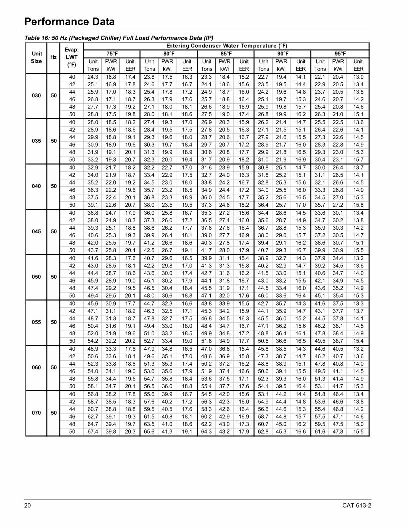
Table 16: 50 Hz (Packaged Chiller) Full Load Performance Data (IP)
Unit PWR Unit Unit PWR Unit Unit PWR Unit Unit PWR Unit Unit PWR UnitTons kWi EER Tons kWi EER Tons kWi EER Tons kWi EER Tons kWi EER
40 24.3 16.8 17.4 23.8 17.5 16.3 23.3 18.4 15.2 22.7 19.4 14.1 22.1 20.4 13.042 25.1 16.9 17.8 24.6 17.7 16.7 24.1 18.6 15.6 23.5 19.5 14.4 22.9 20.5 13.444 25.9 17.0 18.3 25.4 17.8 17.2 24.9 18.7 16.0 24.2 19.6 14.8 23.7 20.5 13.846 26.8 17.1 18.7 26.3 17.9 17.6 25.7 18.8 16.4 25.1 19.7 15.3 24.6 20.7 14.248 27.7 17.3 19.2 27.1 18.0 18.1 26.6 18.9 16.9 25.9 19.8 15.7 25.4 20.8 14.650 28.8 17.5 19.8 28.0 18.1 18.6 27.5 19.0 17.4 26.8 19.9 16.2 26.3 21.0 15.1
40 28.0 18.5 18.2 27.4 19.3 17.0 26.9 20.3 15.9 26.2 21.4 14.7 25.5 22.5 13.642 28.9 18.6 18.6 28.4 19.5 17.5 27.8 20.5 16.3 27.1 21.5 15.1 26.4 22.6 14.144 29.9 18.8 19.1 29.3 19.6 18.0 28.7 20.6 16.7 27.9 21.6 15.5 27.3 22.6 14.546 30.9 18.9 19.6 30.3 19.7 18.4 29.7 20.7 17.2 28.9 21.7 16.0 28.3 22.8 14.948 31.9 19.1 20.1 31.3 19.9 18.9 30.6 20.8 17.7 29.9 21.8 16.5 29.3 23.0 15.350 33.2 19.3 20.7 32.3 20.0 19.4 31.7 20.9 18.2 31.0 21.9 16.9 30.4 23.1 15.7
40 32.9 21.7 18.2 32.2 22.7 17.0 31.6 23.9 15.9 30.8 25.1 14.7 30.0 26.4 13.742 34.0 21.9 18.7 33.4 22.9 17.5 32.7 24.0 16.3 31.8 25.2 15.1 31.1 26.5 14.144 35.2 22.0 19.2 34.5 23.0 18.0 33.8 24.2 16.7 32.8 25.3 15.6 32.1 26.6 14.546 36.3 22.2 19.6 35.7 23.2 18.5 34.9 24.4 17.2 34.0 25.5 16.0 33.3 26.8 14.948 37.5 22.4 20.1 36.8 23.3 18.9 36.0 24.5 17.7 35.2 25.6 16.5 34.5 27.0 15.350 39.1 22.6 20.7 38.0 23.5 19.5 37.3 24.6 18.2 36.4 25.7 17.0 35.7 27.2 15.8
40 36.8 24.7 17.9 36.0 25.8 16.7 35.3 27.2 15.6 34.4 28.6 14.5 33.6 30.1 13.442 38.0 24.9 18.3 37.3 26.0 17.2 36.5 27.4 16.0 35.6 28.7 14.9 34.7 30.2 13.844 39.3 25.1 18.8 38.6 26.2 17.7 37.8 27.6 16.4 36.7 28.8 15.3 35.9 30.3 14.246 40.6 25.3 19.3 39.9 26.4 18.1 39.0 27.7 16.9 38.0 29.0 15.7 37.2 30.5 14.748 42.0 25.5 19.7 41.2 26.6 18.6 40.3 27.8 17.4 39.4 29.1 16.2 38.6 30.7 15.150 43.7 25.8 20.4 42.5 26.7 19.1 41.7 28.0 17.9 40.7 29.3 16.7 39.9 30.9 15.5
40 41.6 28.3 17.6 40.7 29.6 16.5 39.9 31.1 15.4 38.9 32.7 14.3 37.9 34.4 13.242 43.0 28.5 18.1 42.2 29.8 17.0 41.3 31.3 15.8 40.2 32.9 14.7 39.2 34.5 13.644 44.4 28.7 18.6 43.6 30.0 17.4 42.7 31.6 16.2 41.5 33.0 15.1 40.6 34.7 14.046 45.9 28.9 19.0 45.1 30.2 17.9 44.1 31.8 16.7 43.0 33.2 15.5 42.1 34.9 14.548 47.4 29.2 19.5 46.5 30.4 18.4 45.5 31.9 17.1 44.5 33.4 16.0 43.6 35.2 14.950 49.4 29.5 20.1 48.0 30.6 18.8 47.1 32.0 17.6 46.0 33.6 16.4 45.1 35.4 15.3
40 45.6 30.9 17.7 44.7 32.3 16.6 43.8 33.9 15.5 42.7 35.7 14.3 41.6 37.5 13.342 47.1 31.1 18.2 46.3 32.5 17.1 45.3 34.2 15.9 44.1 35.9 14.7 43.1 37.7 13.744 48.7 31.3 18.7 47.8 32.7 17.5 46.8 34.5 16.3 45.5 36.0 15.2 44.5 37.8 14.146 50.4 31.6 19.1 49.4 33.0 18.0 48.4 34.7 16.7 47.1 36.2 15.6 46.2 38.1 14.548 52.0 31.9 19.6 51.0 33.2 18.5 49.9 34.8 17.2 48.8 36.4 16.1 47.8 38.4 14.950 54.2 32.2 20.2 52.7 33.4 19.0 51.6 34.9 17.7 50.5 36.6 16.5 49.5 38.7 15.4
40 48.9 33.3 17.6 47.9 34.8 16.5 47.0 36.6 15.4 45.8 38.5 14.3 44.6 40.5 13.242 50.6 33.6 18.1 49.6 35.1 17.0 48.6 36.9 15.8 47.3 38.7 14.7 46.2 40.7 13.644 52.3 33.8 18.6 51.3 35.3 17.4 50.2 37.2 16.2 48.8 38.9 15.1 47.8 40.8 14.046 54.0 34.1 19.0 53.0 35.6 17.9 51.9 37.4 16.6 50.6 39.1 15.5 49.5 41.1 14.548 55.8 34.4 19.5 54.7 35.8 18.4 53.6 37.5 17.1 52.3 39.3 16.0 51.3 41.4 14.950 58.1 34.7 20.1 56.5 36.0 18.8 55.4 37.7 17.6 54.1 39.5 16.4 53.1 41.7 15.3
40 56.8 38.2 17.8 55.6 39.9 16.7 54.5 42.0 15.6 53.1 44.2 14.4 51.8 46.4 13.442 58.7 38.5 18.3 57.6 40.2 17.2 56.3 42.3 16.0 54.9 44.4 14.8 53.6 46.6 13.844 60.7 38.8 18.8 59.5 40.5 17.6 58.3 42.6 16.4 56.6 44.6 15.3 55.4 46.8 14.246 62.7 39.1 19.3 61.5 40.8 18.1 60.2 42.9 16.9 58.7 44.8 15.7 57.5 47.1 14.648 64.7 39.4 19.7 63.5 41.0 18.6 62.2 43.0 17.3 60.7 45.0 16.2 59.5 47.5 15.050 67.4 39.8 20.3 65.6 41.3 19.1 64.3 43.2 17.9 62.8 45.3 16.6 61.6 47.8 15.5
95°F
030 50
035 50
Unit Size
Hz
050 50
055 50
Evap.LWT(°F)
Entering Condenser Water Temperature (°F)
75°F 80°F 85°F 90°F
040 50
045 50
060 50
070 50
CAT 613-2 21
Performance Data
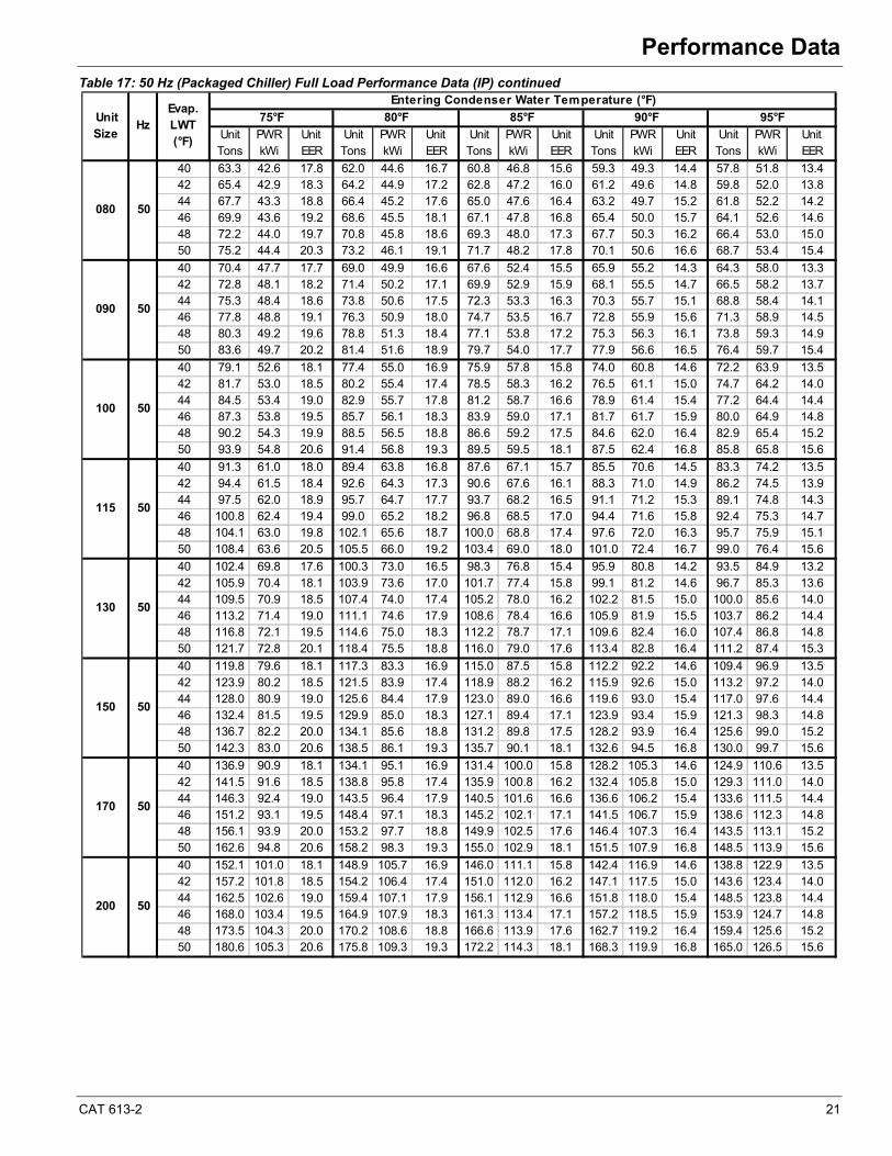
Table 17: 50 Hz (Packaged Chiller) Full Load Performance Data (IP) continued
Unit PWR Unit Unit PWR Unit Unit PWR Unit Unit PWR Unit Unit PWR UnitTons kWi EER Tons kWi EER Tons kWi EER Tons kWi EER Tons kWi EER
40 63.3 42.6 17.8 62.0 44.6 16.7 60.8 46.8 15.6 59.3 49.3 14.4 57.8 51.8 13.442 65.4 42.9 18.3 64.2 44.9 17.2 62.8 47.2 16.0 61.2 49.6 14.8 59.8 52.0 13.844 67.7 43.3 18.8 66.4 45.2 17.6 65.0 47.6 16.4 63.2 49.7 15.2 61.8 52.2 14.246 69.9 43.6 19.2 68.6 45.5 18.1 67.1 47.8 16.8 65.4 50.0 15.7 64.1 52.6 14.648 72.2 44.0 19.7 70.8 45.8 18.6 69.3 48.0 17.3 67.7 50.3 16.2 66.4 53.0 15.050 75.2 44.4 20.3 73.2 46.1 19.1 71.7 48.2 17.8 70.1 50.6 16.6 68.7 53.4 15.4
40 70.4 47.7 17.7 69.0 49.9 16.6 67.6 52.4 15.5 65.9 55.2 14.3 64.3 58.0 13.342 72.8 48.1 18.2 71.4 50.2 17.1 69.9 52.9 15.9 68.1 55.5 14.7 66.5 58.2 13.744 75.3 48.4 18.6 73.8 50.6 17.5 72.3 53.3 16.3 70.3 55.7 15.1 68.8 58.4 14.146 77.8 48.8 19.1 76.3 50.9 18.0 74.7 53.5 16.7 72.8 55.9 15.6 71.3 58.9 14.548 80.3 49.2 19.6 78.8 51.3 18.4 77.1 53.8 17.2 75.3 56.3 16.1 73.8 59.3 14.950 83.6 49.7 20.2 81.4 51.6 18.9 79.7 54.0 17.7 77.9 56.6 16.5 76.4 59.7 15.4
40 79.1 52.6 18.1 77.4 55.0 16.9 75.9 57.8 15.8 74.0 60.8 14.6 72.2 63.9 13.542 81.7 53.0 18.5 80.2 55.4 17.4 78.5 58.3 16.2 76.5 61.1 15.0 74.7 64.2 14.044 84.5 53.4 19.0 82.9 55.7 17.8 81.2 58.7 16.6 78.9 61.4 15.4 77.2 64.4 14.446 87.3 53.8 19.5 85.7 56.1 18.3 83.9 59.0 17.1 81.7 61.7 15.9 80.0 64.9 14.848 90.2 54.3 19.9 88.5 56.5 18.8 86.6 59.2 17.5 84.6 62.0 16.4 82.9 65.4 15.250 93.9 54.8 20.6 91.4 56.8 19.3 89.5 59.5 18.1 87.5 62.4 16.8 85.8 65.8 15.6
40 91.3 61.0 18.0 89.4 63.8 16.8 87.6 67.1 15.7 85.5 70.6 14.5 83.3 74.2 13.542 94.4 61.5 18.4 92.6 64.3 17.3 90.6 67.6 16.1 88.3 71.0 14.9 86.2 74.5 13.944 97.5 62.0 18.9 95.7 64.7 17.7 93.7 68.2 16.5 91.1 71.2 15.3 89.1 74.8 14.346 100.8 62.4 19.4 99.0 65.2 18.2 96.8 68.5 17.0 94.4 71.6 15.8 92.4 75.3 14.748 104.1 63.0 19.8 102.1 65.6 18.7 100.0 68.8 17.4 97.6 72.0 16.3 95.7 75.9 15.150 108.4 63.6 20.5 105.5 66.0 19.2 103.4 69.0 18.0 101.0 72.4 16.7 99.0 76.4 15.6
40 102.4 69.8 17.6 100.3 73.0 16.5 98.3 76.8 15.4 95.9 80.8 14.2 93.5 84.9 13.242 105.9 70.4 18.1 103.9 73.6 17.0 101.7 77.4 15.8 99.1 81.2 14.6 96.7 85.3 13.644 109.5 70.9 18.5 107.4 74.0 17.4 105.2 78.0 16.2 102.2 81.5 15.0 100.0 85.6 14.046 113.2 71.4 19.0 111.1 74.6 17.9 108.6 78.4 16.6 105.9 81.9 15.5 103.7 86.2 14.448 116.8 72.1 19.5 114.6 75.0 18.3 112.2 78.7 17.1 109.6 82.4 16.0 107.4 86.8 14.850 121.7 72.8 20.1 118.4 75.5 18.8 116.0 79.0 17.6 113.4 82.8 16.4 111.2 87.4 15.3
40 119.8 79.6 18.1 117.3 83.3 16.9 115.0 87.5 15.8 112.2 92.2 14.6 109.4 96.9 13.542 123.9 80.2 18.5 121.5 83.9 17.4 118.9 88.2 16.2 115.9 92.6 15.0 113.2 97.2 14.044 128.0 80.9 19.0 125.6 84.4 17.9 123.0 89.0 16.6 119.6 93.0 15.4 117.0 97.6 14.446 132.4 81.5 19.5 129.9 85.0 18.3 127.1 89.4 17.1 123.9 93.4 15.9 121.3 98.3 14.848 136.7 82.2 20.0 134.1 85.6 18.8 131.2 89.8 17.5 128.2 93.9 16.4 125.6 99.0 15.250 142.3 83.0 20.6 138.5 86.1 19.3 135.7 90.1 18.1 132.6 94.5 16.8 130.0 99.7 15.6
40 136.9 90.9 18.1 134.1 95.1 16.9 131.4 100.0 15.8 128.2 105.3 14.6 124.9 110.6 13.542 141.5 91.6 18.5 138.8 95.8 17.4 135.9 100.8 16.2 132.4 105.8 15.0 129.3 111.0 14.044 146.3 92.4 19.0 143.5 96.4 17.9 140.5 101.6 16.6 136.6 106.2 15.4 133.6 111.5 14.446 151.2 93.1 19.5 148.4 97.1 18.3 145.2 102.1 17.1 141.5 106.7 15.9 138.6 112.3 14.848 156.1 93.9 20.0 153.2 97.7 18.8 149.9 102.5 17.6 146.4 107.3 16.4 143.5 113.1 15.250 162.6 94.8 20.6 158.2 98.3 19.3 155.0 102.9 18.1 151.5 107.9 16.8 148.5 113.9 15.6
40 152.1 101.0 18.1 148.9 105.7 16.9 146.0 111.1 15.8 142.4 116.9 14.6 138.8 122.9 13.542 157.2 101.8 18.5 154.2 106.4 17.4 151.0 112.0 16.2 147.1 117.5 15.0 143.6 123.4 14.044 162.5 102.6 19.0 159.4 107.1 17.9 156.1 112.9 16.6 151.8 118.0 15.4 148.5 123.8 14.446 168.0 103.4 19.5 164.9 107.9 18.3 161.3 113.4 17.1 157.2 118.5 15.9 153.9 124.7 14.848 173.5 104.3 20.0 170.2 108.6 18.8 166.6 113.9 17.6 162.7 119.2 16.4 159.4 125.6 15.250 180.6 105.3 20.6 175.8 109.3 19.3 172.2 114.3 18.1 168.3 119.9 16.8 165.0 126.5 15.6
080 50
090 50
Unit Size
HzEvap.LWT(°F)
Entering Condenser Water Temperature (°F)
75°F 80°F 85°F 90°F 95°F
170 50
200 50
130 50
150 50
100 50
115 50
22 CAT 613-2
Performance Data
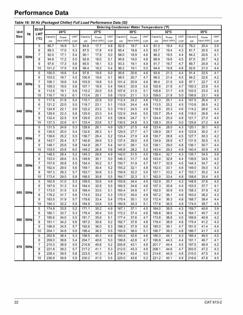
Table 18: 50 Hz (Packaged Chiller) Full Load Performance Data (SI)
Capacity UNIT Capacity UNIT Capacity UNIT Capacity UNIT Capacity UNIT
kW COP kW COP kW COP kW COP kW COP
5 86.7 16.9 5.1 84.8 17.7 4.8 82.9 18.7 4.4 81.3 19.4 4.2 79.2 20.4 3.96 89.3 17.0 5.3 87.5 17.8 4.9 85.4 18.8 4.5 83.7 19.4 4.3 81.7 20.5 4.07 92.0 17.1 5.4 90.1 17.9 5.0 88.0 18.9 4.6 86.2 19.5 4.4 84.2 20.6 4.18 94.8 17.2 5.5 92.8 18.0 5.1 90.6 19.0 4.8 88.9 19.6 4.5 87.0 20.7 4.29 97.6 17.3 5.6 95.5 18.1 5.3 93.3 19.1 4.9 91.7 19.7 4.7 89.7 20.9 4.310 101.2 17.5 5.8 98.4 18.2 5.4 96.2 19.1 5.0 94.6 19.8 4.8 92.6 21.0 4.4
5 100.0 18.6 5.4 97.8 19.5 5.0 95.6 20.6 4.6 93.8 21.3 4.4 91.4 22.5 4.16 103.0 18.7 5.5 100.9 19.6 5.1 98.5 20.7 4.7 96.5 21.4 4.5 94.2 22.6 4.27 106.1 18.8 5.6 103.9 19.8 5.3 101.4 20.9 4.9 99.4 21.5 4.6 97.1 22.7 4.38 109.3 19.0 5.8 107.1 19.9 5.4 104.5 20.9 5.0 102.6 21.6 4.7 100.3 22.8 4.49 112.6 19.1 5.9 110.2 20.0 5.5 107.6 21.0 5.1 105.8 21.7 4.9 103.5 23.0 4.510 116.7 19.3 6.1 113.4 20.1 5.6 110.9 21.1 5.3 109.0 21.8 5.0 106.8 23.1 4.6
5 117.6 21.8 5.4 115.1 22.9 5.0 112.4 24.2 4.6 110.3 25.1 4.4 107.5 26.4 4.16 121.2 22.0 5.5 118.7 23.1 5.1 115.8 24.4 4.8 113.5 25.2 4.5 110.8 26.5 4.27 124.8 22.1 5.6 122.2 23.2 5.3 119.3 24.5 4.9 116.9 25.3 4.6 114.2 26.6 4.38 128.6 22.3 5.8 125.9 23.3 5.4 122.9 24.6 5.0 120.7 25.4 4.8 118.0 26.8 4.49 132.4 22.5 5.9 129.6 23.5 5.5 126.6 24.7 5.1 124.4 25.5 4.9 121.7 27.0 4.510 137.3 22.6 6.1 133.4 23.6 5.7 130.5 24.8 5.3 128.3 25.6 5.0 125.6 27.2 4.6
5 131.5 24.8 5.3 128.6 26.1 4.9 125.7 27.5 4.6 123.4 28.5 4.3 120.1 30.1 4.06 135.5 25.0 5.4 132.6 26.3 5.1 129.5 27.7 4.7 126.9 28.7 4.4 123.8 30.2 4.17 139.6 25.2 5.5 136.7 26.4 5.2 133.4 27.9 4.8 130.7 28.8 4.5 127.7 30.3 4.28 143.7 25.4 5.7 140.8 26.6 5.3 137.4 28.0 4.9 134.9 28.9 4.7 131.9 30.5 4.39 148.1 25.6 5.8 144.9 26.7 5.4 141.5 28.1 5.0 139.1 29.0 4.8 136.1 30.7 4.410 153.5 25.8 6.0 149.2 26.9 5.6 145.8 28.2 5.2 143.4 29.2 4.9 140.4 30.9 4.5
5 148.5 28.4 5.2 145.3 29.9 4.9 142.0 31.5 4.5 139.4 32.7 4.3 135.7 34.5 3.96 153.0 28.6 5.3 149.8 30.1 5.0 146.3 31.7 4.6 143.4 32.8 4.4 139.9 34.6 4.07 157.6 28.8 5.5 154.4 30.2 5.1 150.7 31.9 4.7 147.7 32.9 4.5 144.3 34.7 4.28 162.4 29.0 5.6 159.1 30.4 5.2 155.2 32.1 4.8 152.4 33.1 4.6 149.0 35.0 4.39 167.3 29.3 5.7 163.7 30.6 5.3 159.9 32.2 5.0 157.1 33.2 4.7 153.7 35.2 4.410 173.4 29.5 5.9 168.5 30.8 5.5 164.7 32.3 5.1 162.0 33.4 4.8 158.6 35.4 4.5
5 162.9 31.0 5.3 159.5 32.6 4.9 155.8 34.4 4.5 152.9 35.7 4.3 148.9 37.6 4.06 167.9 31.3 5.4 164.4 32.8 5.0 160.5 34.6 4.6 157.3 35.8 4.4 153.5 37.7 4.17 173.0 31.5 5.5 169.4 33.0 5.1 165.4 34.8 4.7 162.0 35.9 4.5 158.3 37.9 4.28 178.2 31.7 5.6 174.5 33.2 5.3 170.3 35.0 4.9 167.2 36.1 4.6 163.5 38.2 4.39 183.5 31.9 5.7 179.6 33.4 5.4 175.4 35.1 5.0 172.4 36.3 4.8 168.7 38.4 4.410 190.3 32.2 5.9 184.9 33.6 5.5 180.8 35.3 5.1 177.8 36.5 4.9 174.0 38.7 4.5
5 174.8 33.5 5.2 171.1 35.2 4.9 167.1 37.1 4.5 164.0 38.5 4.3 159.7 40.6 3.96 180.1 33.7 5.3 176.4 35.4 5.0 172.2 37.4 4.6 168.8 38.6 4.4 164.7 40.7 4.07 185.6 34.0 5.5 181.7 35.6 5.1 177.4 37.6 4.7 173.8 38.8 4.5 169.8 40.9 4.28 191.1 34.2 5.6 187.2 35.8 5.2 182.7 37.8 4.8 179.4 38.9 4.6 175.4 41.2 4.39 196.9 34.5 5.7 192.6 36.0 5.3 188.2 37.9 5.0 185.0 39.1 4.7 181.0 41.4 4.410 204.1 34.8 5.9 198.4 36.2 5.5 193.9 38.0 5.1 190.7 39.3 4.8 186.7 41.7 4.5
5 202.8 38.4 5.3 198.5 40.3 4.9 193.9 42.6 4.6 190.3 44.1 4.3 185.4 46.5 4.06 209.0 38.6 5.4 204.7 40.6 5.0 199.8 42.8 4.7 195.8 44.3 4.4 191.1 46.7 4.17 215.3 38.9 5.5 210.8 40.8 5.2 205.8 43.1 4.8 201.7 44.4 4.5 197.0 46.9 4.28 221.8 39.2 5.7 217.2 41.1 5.3 212.0 43.3 4.9 208.1 44.6 4.7 203.5 47.2 4.39 228.4 39.5 5.8 223.5 41.3 5.4 218.4 43.4 5.0 214.6 44.9 4.8 210.0 47.5 4.410 236.8 39.8 5.9 230.2 41.5 5.5 225.0 43.6 5.2 221.2 45.1 4.9 216.6 47.8 4.5
030 50Hz
035 50Hz
50Hz
045 50Hz
Unit Size
HzEVAP LWT (°C)
Entering Condenser Water Temperature (°F)
24°C 27°C 30°C 32°C 35°C
Power Input (kWi)
Power Input (kWi)
060 50Hz
070 50Hz
050 50Hz
055 50Hz
040
Power Input (kWi)
Power Input (kWi)
Power Input (kWi)
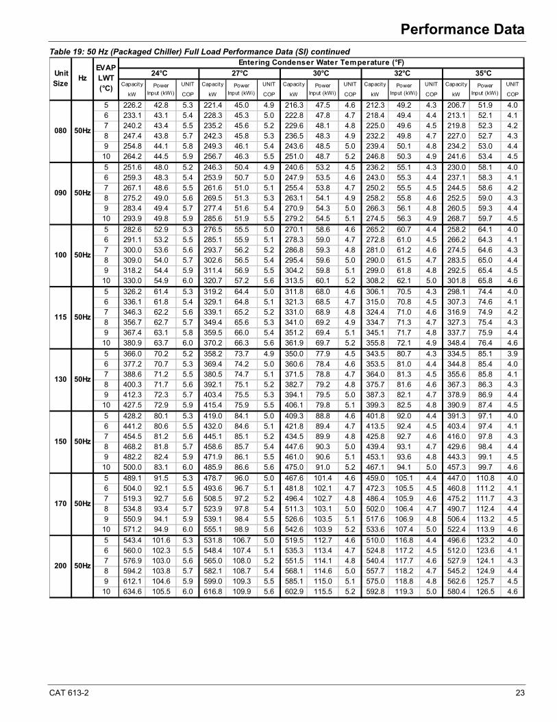
CAT 613-2 23
Performance Data
Table 19: 50 Hz (Packaged Chiller) Full Load Performance Data (SI) continued
Capacity UNIT Capacity UNIT Capacity UNIT Capacity UNIT Capacity UNIT
kW COP kW COP kW COP kW COP kW COP
5 226.2 42.8 5.3 221.4 45.0 4.9 216.3 47.5 4.6 212.3 49.2 4.3 206.7 51.9 4.06 233.1 43.1 5.4 228.3 45.3 5.0 222.8 47.8 4.7 218.4 49.4 4.4 213.1 52.1 4.17 240.2 43.4 5.5 235.2 45.6 5.2 229.6 48.1 4.8 225.0 49.6 4.5 219.8 52.3 4.28 247.4 43.8 5.7 242.3 45.8 5.3 236.5 48.3 4.9 232.2 49.8 4.7 227.0 52.7 4.39 254.8 44.1 5.8 249.3 46.1 5.4 243.6 48.5 5.0 239.4 50.1 4.8 234.2 53.0 4.410 264.2 44.5 5.9 256.7 46.3 5.5 251.0 48.7 5.2 246.8 50.3 4.9 241.6 53.4 4.5
5 251.6 48.0 5.2 246.3 50.4 4.9 240.6 53.2 4.5 236.2 55.1 4.3 230.0 58.1 4.06 259.3 48.3 5.4 253.9 50.7 5.0 247.9 53.5 4.6 243.0 55.3 4.4 237.1 58.3 4.17 267.1 48.6 5.5 261.6 51.0 5.1 255.4 53.8 4.7 250.2 55.5 4.5 244.5 58.6 4.28 275.2 49.0 5.6 269.5 51.3 5.3 263.1 54.1 4.9 258.2 55.8 4.6 252.5 59.0 4.39 283.4 49.4 5.7 277.4 51.6 5.4 270.9 54.3 5.0 266.3 56.1 4.8 260.5 59.3 4.410 293.9 49.8 5.9 285.6 51.9 5.5 279.2 54.5 5.1 274.5 56.3 4.9 268.7 59.7 4.5
5 282.6 52.9 5.3 276.5 55.5 5.0 270.1 58.6 4.6 265.2 60.7 4.4 258.2 64.1 4.06 291.1 53.2 5.5 285.1 55.9 5.1 278.3 59.0 4.7 272.8 61.0 4.5 266.2 64.3 4.17 300.0 53.6 5.6 293.7 56.2 5.2 286.8 59.3 4.8 281.0 61.2 4.6 274.5 64.6 4.38 309.0 54.0 5.7 302.6 56.5 5.4 295.4 59.6 5.0 290.0 61.5 4.7 283.5 65.0 4.49 318.2 54.4 5.9 311.4 56.9 5.5 304.2 59.8 5.1 299.0 61.8 4.8 292.5 65.4 4.510 330.0 54.9 6.0 320.7 57.2 5.6 313.5 60.1 5.2 308.2 62.1 5.0 301.8 65.8 4.6
5 326.2 61.4 5.3 319.2 64.4 5.0 311.8 68.0 4.6 306.1 70.5 4.3 298.1 74.4 4.06 336.1 61.8 5.4 329.1 64.8 5.1 321.3 68.5 4.7 315.0 70.8 4.5 307.3 74.6 4.17 346.3 62.2 5.6 339.1 65.2 5.2 331.0 68.9 4.8 324.4 71.0 4.6 316.9 74.9 4.28 356.7 62.7 5.7 349.4 65.6 5.3 341.0 69.2 4.9 334.7 71.3 4.7 327.3 75.4 4.39 367.4 63.1 5.8 359.5 66.0 5.4 351.2 69.4 5.1 345.1 71.7 4.8 337.7 75.9 4.410 380.9 63.7 6.0 370.2 66.3 5.6 361.9 69.7 5.2 355.8 72.1 4.9 348.4 76.4 4.6
5 366.0 70.2 5.2 358.2 73.7 4.9 350.0 77.9 4.5 343.5 80.7 4.3 334.5 85.1 3.96 377.2 70.7 5.3 369.4 74.2 5.0 360.6 78.4 4.6 353.5 81.0 4.4 344.8 85.4 4.07 388.6 71.2 5.5 380.5 74.7 5.1 371.5 78.8 4.7 364.0 81.3 4.5 355.6 85.8 4.18 400.3 71.7 5.6 392.1 75.1 5.2 382.7 79.2 4.8 375.7 81.6 4.6 367.3 86.3 4.39 412.3 72.3 5.7 403.4 75.5 5.3 394.1 79.5 5.0 387.3 82.1 4.7 378.9 86.9 4.410 427.5 72.9 5.9 415.4 75.9 5.5 406.1 79.8 5.1 399.3 82.5 4.8 390.9 87.4 4.5
5 428.2 80.1 5.3 419.0 84.1 5.0 409.3 88.8 4.6 401.8 92.0 4.4 391.3 97.1 4.06 441.2 80.6 5.5 432.0 84.6 5.1 421.8 89.4 4.7 413.5 92.4 4.5 403.4 97.4 4.17 454.5 81.2 5.6 445.1 85.1 5.2 434.5 89.9 4.8 425.8 92.7 4.6 416.0 97.8 4.38 468.2 81.8 5.7 458.6 85.7 5.4 447.6 90.3 5.0 439.4 93.1 4.7 429.6 98.4 4.49 482.2 82.4 5.9 471.9 86.1 5.5 461.0 90.6 5.1 453.1 93.6 4.8 443.3 99.1 4.510 500.0 83.1 6.0 485.9 86.6 5.6 475.0 91.0 5.2 467.1 94.1 5.0 457.3 99.7 4.6
5 489.1 91.5 5.3 478.7 96.0 5.0 467.6 101.4 4.6 459.0 105.1 4.4 447.0 110.8 4.06 504.0 92.1 5.5 493.6 96.7 5.1 481.8 102.1 4.7 472.3 105.5 4.5 460.8 111.2 4.17 519.3 92.7 5.6 508.5 97.2 5.2 496.4 102.7 4.8 486.4 105.9 4.6 475.2 111.7 4.38 534.8 93.4 5.7 523.9 97.8 5.4 511.3 103.1 5.0 502.0 106.4 4.7 490.7 112.4 4.49 550.9 94.1 5.9 539.1 98.4 5.5 526.6 103.5 5.1 517.6 106.9 4.8 506.4 113.2 4.510 571.2 94.9 6.0 555.1 98.9 5.6 542.6 103.9 5.2 533.6 107.4 5.0 522.4 113.9 4.6
5 543.4 101.6 5.3 531.8 106.7 5.0 519.5 112.7 4.6 510.0 116.8 4.4 496.6 123.2 4.06 560.0 102.3 5.5 548.4 107.4 5.1 535.3 113.4 4.7 524.8 117.2 4.5 512.0 123.6 4.17 576.9 103.0 5.6 565.0 108.0 5.2 551.5 114.1 4.8 540.4 117.7 4.6 527.9 124.1 4.38 594.2 103.8 5.7 582.1 108.7 5.4 568.1 114.6 5.0 557.7 118.2 4.7 545.2 124.9 4.49 612.1 104.6 5.9 599.0 109.3 5.5 585.1 115.0 5.1 575.0 118.8 4.8 562.6 125.7 4.510 634.6 105.5 6.0 616.8 109.9 5.6 602.9 115.5 5.2 592.8 119.3 5.0 580.4 126.5 4.6
080 50Hz
090 50Hz
Unit Size
Hz24°C 27°C 30°C 32°C 35°C
Power Input (kWi)
170 50Hz
200 50Hz
130 50Hz
150 50Hz
100 50Hz
115 50Hz
Power Input (kWi)
Power Input (kWi)
Power Input (kWi)
Power Input (kWi)
EVAP LWT (°C)
Entering Condenser Water Temperature (°F)
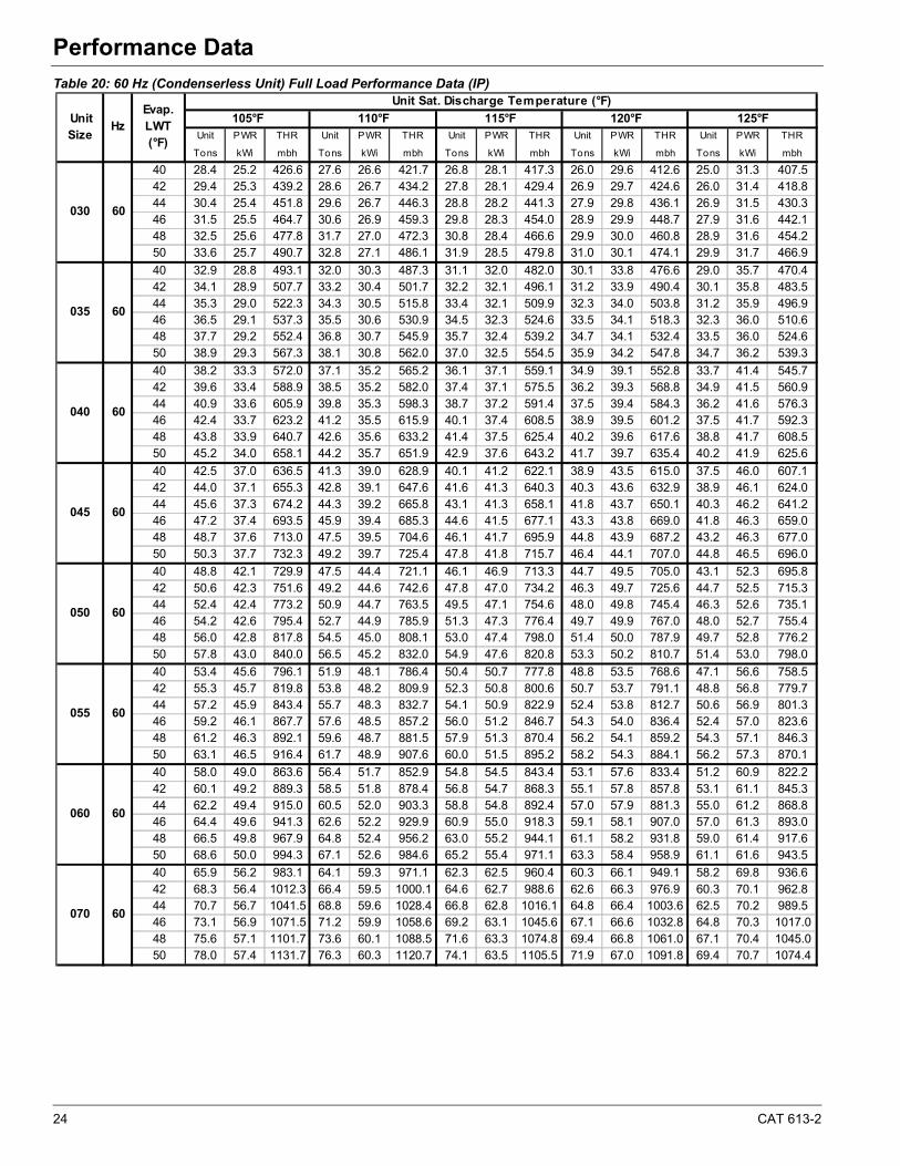
24 CAT 613-2
Performance Data
Table 20: 60 Hz (Condenserless Unit) Full Load Performance Data (IP)
Unit PWR THR Unit PWR THR Unit PWR THR Unit PWR THR Unit PWR THR
Tons kWi mbh Tons kWi mbh Tons kWi mbh Tons kWi mbh Tons kWi mbh
40 28.4 25.2 426.6 27.6 26.6 421.7 26.8 28.1 417.3 26.0 29.6 412.6 25.0 31.3 407.542 29.4 25.3 439.2 28.6 26.7 434.2 27.8 28.1 429.4 26.9 29.7 424.6 26.0 31.4 418.844 30.4 25.4 451.8 29.6 26.7 446.3 28.8 28.2 441.3 27.9 29.8 436.1 26.9 31.5 430.346 31.5 25.5 464.7 30.6 26.9 459.3 29.8 28.3 454.0 28.9 29.9 448.7 27.9 31.6 442.148 32.5 25.6 477.8 31.7 27.0 472.3 30.8 28.4 466.6 29.9 30.0 460.8 28.9 31.6 454.250 33.6 25.7 490.7 32.8 27.1 486.1 31.9 28.5 479.8 31.0 30.1 474.1 29.9 31.7 466.9
40 32.9 28.8 493.1 32.0 30.3 487.3 31.1 32.0 482.0 30.1 33.8 476.6 29.0 35.7 470.442 34.1 28.9 507.7 33.2 30.4 501.7 32.2 32.1 496.1 31.2 33.9 490.4 30.1 35.8 483.544 35.3 29.0 522.3 34.3 30.5 515.8 33.4 32.1 509.9 32.3 34.0 503.8 31.2 35.9 496.946 36.5 29.1 537.3 35.5 30.6 530.9 34.5 32.3 524.6 33.5 34.1 518.3 32.3 36.0 510.648 37.7 29.2 552.4 36.8 30.7 545.9 35.7 32.4 539.2 34.7 34.1 532.4 33.5 36.0 524.650 38.9 29.3 567.3 38.1 30.8 562.0 37.0 32.5 554.5 35.9 34.2 547.8 34.7 36.2 539.3
40 38.2 33.3 572.0 37.1 35.2 565.2 36.1 37.1 559.1 34.9 39.1 552.8 33.7 41.4 545.742 39.6 33.4 588.9 38.5 35.2 582.0 37.4 37.1 575.5 36.2 39.3 568.8 34.9 41.5 560.944 40.9 33.6 605.9 39.8 35.3 598.3 38.7 37.2 591.4 37.5 39.4 584.3 36.2 41.6 576.346 42.4 33.7 623.2 41.2 35.5 615.9 40.1 37.4 608.5 38.9 39.5 601.2 37.5 41.7 592.348 43.8 33.9 640.7 42.6 35.6 633.2 41.4 37.5 625.4 40.2 39.6 617.6 38.8 41.7 608.550 45.2 34.0 658.1 44.2 35.7 651.9 42.9 37.6 643.2 41.7 39.7 635.4 40.2 41.9 625.6
40 42.5 37.0 636.5 41.3 39.0 628.9 40.1 41.2 622.1 38.9 43.5 615.0 37.5 46.0 607.142 44.0 37.1 655.3 42.8 39.1 647.6 41.6 41.3 640.3 40.3 43.6 632.9 38.9 46.1 624.044 45.6 37.3 674.2 44.3 39.2 665.8 43.1 41.3 658.1 41.8 43.7 650.1 40.3 46.2 641.246 47.2 37.4 693.5 45.9 39.4 685.3 44.6 41.5 677.1 43.3 43.8 669.0 41.8 46.3 659.048 48.7 37.6 713.0 47.5 39.5 704.6 46.1 41.7 695.9 44.8 43.9 687.2 43.2 46.3 677.050 50.3 37.7 732.3 49.2 39.7 725.4 47.8 41.8 715.7 46.4 44.1 707.0 44.8 46.5 696.0
40 48.8 42.1 729.9 47.5 44.4 721.1 46.1 46.9 713.3 44.7 49.5 705.0 43.1 52.3 695.842 50.6 42.3 751.6 49.2 44.6 742.6 47.8 47.0 734.2 46.3 49.7 725.6 44.7 52.5 715.344 52.4 42.4 773.2 50.9 44.7 763.5 49.5 47.1 754.6 48.0 49.8 745.4 46.3 52.6 735.146 54.2 42.6 795.4 52.7 44.9 785.9 51.3 47.3 776.4 49.7 49.9 767.0 48.0 52.7 755.448 56.0 42.8 817.8 54.5 45.0 808.1 53.0 47.4 798.0 51.4 50.0 787.9 49.7 52.8 776.250 57.8 43.0 840.0 56.5 45.2 832.0 54.9 47.6 820.8 53.3 50.2 810.7 51.4 53.0 798.0
40 53.4 45.6 796.1 51.9 48.1 786.4 50.4 50.7 777.8 48.8 53.5 768.6 47.1 56.6 758.542 55.3 45.7 819.8 53.8 48.2 809.9 52.3 50.8 800.6 50.7 53.7 791.1 48.8 56.8 779.744 57.2 45.9 843.4 55.7 48.3 832.7 54.1 50.9 822.9 52.4 53.8 812.7 50.6 56.9 801.346 59.2 46.1 867.7 57.6 48.5 857.2 56.0 51.2 846.7 54.3 54.0 836.4 52.4 57.0 823.648 61.2 46.3 892.1 59.6 48.7 881.5 57.9 51.3 870.4 56.2 54.1 859.2 54.3 57.1 846.350 63.1 46.5 916.4 61.7 48.9 907.6 60.0 51.5 895.2 58.2 54.3 884.1 56.2 57.3 870.1
40 58.0 49.0 863.6 56.4 51.7 852.9 54.8 54.5 843.4 53.1 57.6 833.4 51.2 60.9 822.242 60.1 49.2 889.3 58.5 51.8 878.4 56.8 54.7 868.3 55.1 57.8 857.8 53.1 61.1 845.344 62.2 49.4 915.0 60.5 52.0 903.3 58.8 54.8 892.4 57.0 57.9 881.3 55.0 61.2 868.846 64.4 49.6 941.3 62.6 52.2 929.9 60.9 55.0 918.3 59.1 58.1 907.0 57.0 61.3 893.048 66.5 49.8 967.9 64.8 52.4 956.2 63.0 55.2 944.1 61.1 58.2 931.8 59.0 61.4 917.650 68.6 50.0 994.3 67.1 52.6 984.6 65.2 55.4 971.1 63.3 58.4 958.9 61.1 61.6 943.5
40 65.9 56.2 983.1 64.1 59.3 971.1 62.3 62.5 960.4 60.3 66.1 949.1 58.2 69.8 936.642 68.3 56.4 1012.3 66.4 59.5 1000.1 64.6 62.7 988.6 62.6 66.3 976.9 60.3 70.1 962.844 70.7 56.7 1041.5 68.8 59.6 1028.4 66.8 62.8 1016.1 64.8 66.4 1003.6 62.5 70.2 989.546 73.1 56.9 1071.5 71.2 59.9 1058.6 69.2 63.1 1045.6 67.1 66.6 1032.8 64.8 70.3 1017.048 75.6 57.1 1101.7 73.6 60.1 1088.5 71.6 63.3 1074.8 69.4 66.8 1061.0 67.1 70.4 1045.050 78.0 57.4 1131.7 76.3 60.3 1120.7 74.1 63.5 1105.5 71.9 67.0 1091.8 69.4 70.7 1074.4
060 60
070 60
045 60
050 60
055 60
030 60
035 60
040 60
Unit Size
HzEvap.LWT(°F)
Unit Sat. Discharge Temperature (°F)
105°F 110°F 115°F 120°F 125°F

CAT 613-2 25
Performance Data
Table 21: 60 Hz (Condenserless Unit) Full Load Performance Data (IP) (continued)
Unit PWR THR Unit PWR THR Unit PWR THR Unit PWR THR Unit PWR THR
Tons kWi mbh Tons kWi mbh Tons kWi mbh Tons kWi mbh Tons kWi mbh
40 74.6 63.6 1112.1 72.5 67.1 1098.5 70.4 70.7 1086.4 68.2 74.7 1073.6 65.8 79.0 1059.442 77.3 63.8 1145.1 75.2 67.3 1131.3 73.0 70.9 1118.3 70.8 75.0 1105.0 68.2 79.2 1089.144 80.0 64.1 1178.2 77.8 67.4 1163.2 75.6 71.1 1149.4 73.2 75.1 1135.2 70.7 79.4 1119.346 82.7 64.3 1212.1 80.5 67.7 1197.4 78.3 71.4 1182.7 75.9 75.4 1168.3 73.2 79.6 1150.448 85.5 64.6 1246.2 83.3 68.0 1231.3 81.0 71.6 1215.8 78.5 75.5 1200.2 75.9 79.6 1182.150 88.2 64.9 1280.1 86.3 68.2 1267.8 83.8 71.9 1250.5 81.4 75.7 1235.0 78.5 80.0 1215.4
40 83.7 71.8 1249.1 81.3 75.8 1234.0 79.0 79.9 1220.5 76.5 84.4 1206.3 73.8 89.3 1190.542 86.7 72.1 1286.2 84.3 76.0 1270.8 81.9 80.1 1256.3 79.4 84.7 1241.5 76.5 89.5 1223.744 89.7 72.4 1323.2 87.2 76.2 1306.6 84.8 80.3 1291.2 82.2 84.9 1275.4 79.3 89.7 1257.746 92.8 72.7 1361.3 90.3 76.5 1344.9 87.8 80.6 1328.6 85.2 85.1 1312.5 82.2 89.9 1292.548 95.9 73.0 1399.6 93.4 76.8 1383.0 90.8 80.9 1365.6 88.1 85.3 1348.3 85.1 90.0 1328.050 99.0 73.3 1437.6 96.7 77.1 1423.9 94.0 81.2 1404.6 91.3 85.6 1387.3 88.1 90.3 1365.4
40 93.6 80.1 1396.2 90.9 84.5 1379.3 88.3 89.1 1364.2 85.6 94.1 1348.2 82.6 99.5 1330.542 96.9 80.4 1437.7 94.3 84.7 1420.5 91.6 89.3 1404.2 88.8 94.4 1387.6 85.6 99.8 1367.744 100.3 80.7 1479.2 97.6 84.9 1460.5 94.8 89.5 1443.2 91.9 94.6 1425.5 88.7 100.0 1405.646 103.8 81.0 1521.7 101.0 85.3 1503.4 98.2 89.9 1485.0 95.3 94.9 1467.0 91.9 100.2 1444.648 107.2 81.4 1564.6 104.5 85.6 1545.9 101.6 90.2 1526.5 98.5 95.1 1507.0 95.2 100.3 1484.350 110.7 81.7 1607.1 108.2 85.9 1591.7 105.1 90.5 1570.1 102.1 95.4 1550.6 98.5 100.7 1526.1
40 107.5 92.1 1604.4 104.4 97.2 1584.9 101.5 102.5 1567.5 98.3 108.2 1549.2 94.9 114.4 1528.842 111.4 92.5 1652.0 108.3 97.4 1632.2 105.3 102.7 1613.5 102.0 108.6 1594.4 98.3 114.8 1571.644 115.2 92.8 1699.6 112.1 97.6 1678.2 108.9 102.9 1658.4 105.6 108.8 1638.0 101.9 115.0 1615.246 119.2 93.2 1748.5 116.1 98.1 1727.5 112.8 103.4 1706.4 109.4 109.1 1685.7 105.6 115.2 1660.048 123.2 93.6 1797.8 120.0 98.4 1776.3 116.7 103.7 1754.0 113.2 109.4 1731.7 109.3 115.3 1705.650 127.2 94.0 1846.6 124.3 98.8 1828.9 120.8 104.1 1804.1 117.3 109.7 1781.8 113.2 115.8 1753.7
40 121.4 104.1 1812.5 118.0 109.9 1790.5 114.6 115.8 1770.9 111.1 122.3 1750.2 107.2 129.4 1727.242 125.8 104.5 1866.3 122.4 110.1 1843.9 118.9 116.1 1822.9 115.2 122.7 1801.3 111.1 129.7 1775.544 130.2 104.9 1920.1 126.6 110.4 1895.9 123.0 116.4 1873.5 119.2 123.0 1850.5 115.1 130.0 1824.846 134.7 105.3 1975.3 131.1 110.9 1951.5 127.4 116.9 1927.7 123.6 123.4 1904.3 119.2 130.3 1875.448 139.2 105.8 2030.9 135.6 111.3 2006.7 131.8 117.3 1981.6 127.9 123.6 1956.3 123.5 130.4 1926.950 143.6 106.2 2086.1 140.4 111.7 2066.1 136.4 117.7 2038.1 132.5 124.0 2012.9 127.9 130.9 1981.2
40 140.4 120.2 2095.0 136.4 126.8 2069.6 132.6 133.7 2046.8 128.4 141.2 2022.9 123.9 149.3 1996.242 145.5 120.6 2157.2 141.5 127.1 2131.3 137.5 134.0 2106.9 133.2 141.6 2081.9 128.4 149.7 2052.144 150.5 121.1 2219.5 146.4 127.4 2191.4 142.3 134.3 2165.5 137.9 141.9 2138.9 133.1 150.0 2109.046 155.7 121.5 2283.3 151.6 128.0 2255.8 147.3 134.9 2228.2 142.9 142.4 2201.1 137.9 150.3 2167.548 160.9 122.1 2347.6 156.8 128.4 2319.6 152.4 135.3 2290.4 147.9 142.7 2261.2 142.8 150.5 2227.150 166.1 122.6 2411.4 162.4 128.9 2388.2 157.7 135.8 2355.9 153.2 143.1 2326.6 147.9 151.1 2289.9
40 162.2 138.2 2417.3 157.5 145.8 2387.9 153.1 153.7 2361.4 148.3 162.3 2333.7 143.1 171.6 2302.842 168.0 138.7 2489.1 163.4 146.1 2459.1 158.8 154.0 2430.9 153.9 162.8 2401.9 148.3 172.2 2367.244 173.8 139.2 2561.0 169.1 146.5 2528.5 164.3 154.4 2498.4 159.2 163.2 2467.6 153.7 172.5 2433.046 179.8 139.7 2634.7 175.1 147.1 2602.8 170.1 155.1 2570.9 165.1 163.7 2539.4 159.2 172.8 2500.548 185.8 140.4 2709.0 181.1 147.7 2676.5 176.0 155.6 2642.7 170.8 164.0 2608.9 164.9 173.0 2569.450 191.8 140.9 2782.7 187.5 148.2 2755.7 182.1 156.1 2718.3 176.9 164.6 2684.4 170.8 173.7 2641.8
40 183.9 156.3 2739.8 178.7 164.9 2706.4 173.6 173.8 2676.4 168.2 183.6 2644.8 162.3 194.1 2609.642 190.5 156.9 2821.3 185.3 165.2 2787.2 180.1 174.2 2755.1 174.5 184.2 2722.1 168.2 194.7 2682.744 197.1 157.4 2902.8 191.7 165.6 2865.9 186.3 174.6 2831.7 180.6 184.6 2796.6 174.3 195.1 2757.346 203.9 158.0 2986.4 198.5 166.4 2950.2 193.0 175.4 2913.8 187.2 185.1 2878.1 180.6 195.5 2833.948 210.7 158.8 3070.6 205.3 167.0 3033.7 199.6 176.0 2995.3 193.6 185.5 2956.8 187.0 195.7 2912.050 217.5 159.4 3154.2 212.6 167.6 3123.6 206.5 176.6 3081.0 200.6 186.1 3042.5 193.6 196.5 2994.1
200 60
130 60
150 60
170 60
090 60
100 60
115 60
080 60
Unit Size
HzEvap.LWT(°F)
Unit Sat. Discharge Temperature (°F)
105°F 110°F 115°F 120°F 125°F
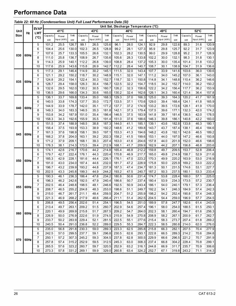
26 CAT 613-2
Performance Data
Table 22: 60 Hz (Condenserless Unit) Full Load Performance Data (SI)
Capacity THR Capacity THR Capacity THR Capacity THR Capacity THR
kW kW kW kW kW kW kW kW kW kW
5 101.2 25.5 126.7 99.1 26.5 125.6 96.1 28.0 124.1 92.9 29.8 122.6 89.3 31.6 120.96 104.4 25.6 130.0 102.3 26.5 128.8 99.2 28.1 127.3 95.9 29.8 125.7 92.2 31.7 123.97 107.6 25.7 133.3 105.5 26.6 132.1 102.3 28.2 130.5 99.0 29.9 128.8 95.2 31.7 126.98 111.0 25.8 136.7 108.9 26.7 135.6 105.6 28.3 133.8 102.2 30.0 132.1 98.3 31.8 130.19 114.3 25.9 140.1 112.2 26.8 139.0 108.8 28.4 137.2 105.3 30.0 135.4 101.4 31.8 133.210 117.6 25.9 143.6 115.8 26.9 142.7 112.2 28.4 140.7 108.7 30.1 138.9 104.7 31.9 136.6
5 117.3 29.1 146.4 114.9 30.2 145.1 111.5 32.0 143.4 107.7 33.9 141.6 103.6 36.0 139.66 121.1 29.2 150.2 118.7 30.2 148.9 115.1 32.0 147.1 111.2 34.0 145.2 107.0 36.1 143.07 124.8 29.2 154.1 122.4 30.3 152.7 118.7 32.1 150.8 114.8 34.1 148.8 110.4 36.2 146.68 128.7 29.4 158.0 126.3 30.4 156.7 122.5 32.2 154.7 118.5 34.2 152.7 114.0 36.2 150.29 132.6 29.5 162.0 130.2 30.5 160.7 126.2 32.3 158.6 122.2 34.2 156.4 117.7 36.2 153.910 136.5 29.6 166.0 134.3 30.6 165.0 130.2 32.4 162.6 126.1 34.3 160.4 121.4 36.4 157.8
5 136.1 33.7 169.8 133.4 35.0 168.3 129.3 37.0 166.3 125.0 39.3 164.3 120.2 41.7 161.96 140.5 33.8 174.3 137.7 35.0 172.7 133.5 37.1 170.6 129.0 39.4 168.4 124.1 41.8 165.97 144.9 33.9 178.7 142.0 35.1 177.2 137.7 37.2 174.9 133.2 39.5 172.6 128.1 41.9 170.08 149.3 34.0 183.3 146.5 35.3 181.8 142.1 37.3 179.4 137.5 39.6 177.1 132.3 42.0 174.29 153.8 34.2 187.9 151.0 35.4 186.4 146.5 37.5 183.9 141.8 39.7 181.4 136.5 42.0 178.510 158.3 34.3 192.6 155.9 35.5 191.4 151.0 37.6 188.6 146.3 39.8 186.1 140.8 42.2 183.0
5 151.5 37.4 188.9 148.5 38.8 187.3 144.0 41.1 185.1 139.1 43.6 182.8 133.8 46.3 180.16 156.4 37.5 193.9 153.3 38.9 192.2 148.6 41.2 189.8 143.7 43.7 187.4 138.1 46.4 184.67 161.3 37.6 198.9 158.1 39.0 197.1 153.3 41.3 194.6 148.2 43.8 192.1 142.6 46.5 189.28 166.2 37.8 204.0 163.1 39.2 202.3 158.2 41.5 199.6 153.1 44.0 197.0 147.2 46.6 193.89 171.2 37.9 209.1 168.1 39.3 207.4 163.0 41.6 204.6 157.8 44.0 201.9 152.0 46.6 198.610 176.3 38.1 214.3 173.5 39.4 212.9 168.1 41.7 209.9 162.9 44.2 207.1 156.8 46.8 203.6
5 174.1 42.6 216.7 170.6 44.2 214.8 165.4 46.8 212.2 159.8 49.7 209.5 153.7 52.8 206.46 179.7 42.7 222.4 176.1 44.3 220.4 170.8 46.9 217.7 165.0 49.8 214.9 158.7 52.9 211.67 185.3 42.9 228.1 181.6 44.4 226.1 176.1 47.0 223.2 170.3 49.9 220.2 163.9 53.0 216.98 191.0 43.0 234.0 187.4 44.6 232.0 181.7 47.2 228.9 175.8 50.0 225.9 169.2 53.0 222.29 196.7 43.2 239.9 193.2 44.8 237.9 187.3 47.4 234.7 181.3 50.1 231.5 174.6 53.1 227.710 202.5 43.3 245.8 199.3 44.9 244.2 193.2 47.5 240.7 187.2 50.3 237.5 180.1 53.3 233.4
5 190.3 46.1 236.3 186.4 47.8 234.2 180.8 50.6 231.4 174.7 53.8 228.4 168.0 57.1 225.06 196.3 46.2 242.6 192.5 47.9 240.4 186.6 50.7 237.4 180.4 53.9 234.3 173.5 57.2 230.77 202.5 46.4 248.8 198.5 48.1 246.6 192.5 50.9 243.4 186.1 54.0 240.1 179.1 57.3 236.48 208.7 46.5 255.2 204.8 48.3 253.0 198.6 51.1 249.7 192.2 54.1 246.3 184.9 57.4 242.39 215.0 46.7 261.7 211.1 48.4 259.5 204.7 51.2 255.9 198.2 54.2 252.4 190.8 57.4 248.310 221.3 46.9 268.2 217.9 48.6 266.4 211.1 51.4 262.5 204.5 54.4 259.0 196.9 57.7 254.5
5 206.8 49.5 256.4 202.6 51.4 254.1 196.5 54.5 251.0 189.9 57.8 247.7 182.6 61.4 243.96 213.4 49.7 263.1 209.2 51.5 260.7 202.9 54.6 257.4 196.1 58.0 254.0 188.5 61.5 250.17 220.1 49.9 269.9 215.8 51.7 267.5 209.2 54.7 264.0 202.3 58.1 260.4 194.7 61.6 256.38 226.9 50.0 276.9 222.6 51.9 274.5 215.9 54.9 270.8 208.9 58.2 267.1 200.9 61.7 262.79 233.7 50.2 283.9 229.4 52.1 281.5 222.5 55.1 277.6 215.4 58.3 273.7 207.4 61.8 269.210 240.5 50.4 291.0 236.8 52.2 289.0 229.5 55.3 284.7 222.3 58.5 280.8 214.0 62.0 276.0
5 235.0 56.8 291.8 230.3 59.0 289.3 223.3 62.5 285.8 215.8 66.3 282.1 207.5 70.4 277.96 242.5 57.0 299.5 237.7 59.1 296.8 230.5 62.6 293.1 222.8 66.5 289.3 214.2 70.6 284.87 250.1 57.2 307.3 245.2 59.3 304.5 237.8 62.8 300.5 229.9 66.6 296.5 221.2 70.7 291.98 257.8 57.4 315.2 252.9 59.5 312.5 245.3 63.0 308.3 237.4 66.8 304.2 228.4 70.8 299.19 265.5 57.6 323.2 260.7 59.7 320.5 252.9 63.2 316.1 244.8 66.9 311.7 235.7 70.9 306.610 273.3 57.8 331.2 269.1 59.9 329.0 260.8 63.4 324.2 252.7 67.1 319.8 243.2 71.1 314.3
060 60Hz
070 60Hz
045 60Hz
050 60Hz
055 60Hz
030 60Hz
035 60Hz
040 60Hz
Unit Size
HzEVAP LWT (°C)
Unit Sat. Discharge Temperature (°C)
41°C 43°C 46°C 49°C 52°C
Power Input (kWi)
Power Input (kWi)
Power Input (kWi)
Power Input (kWi)
Power Input (kWi)
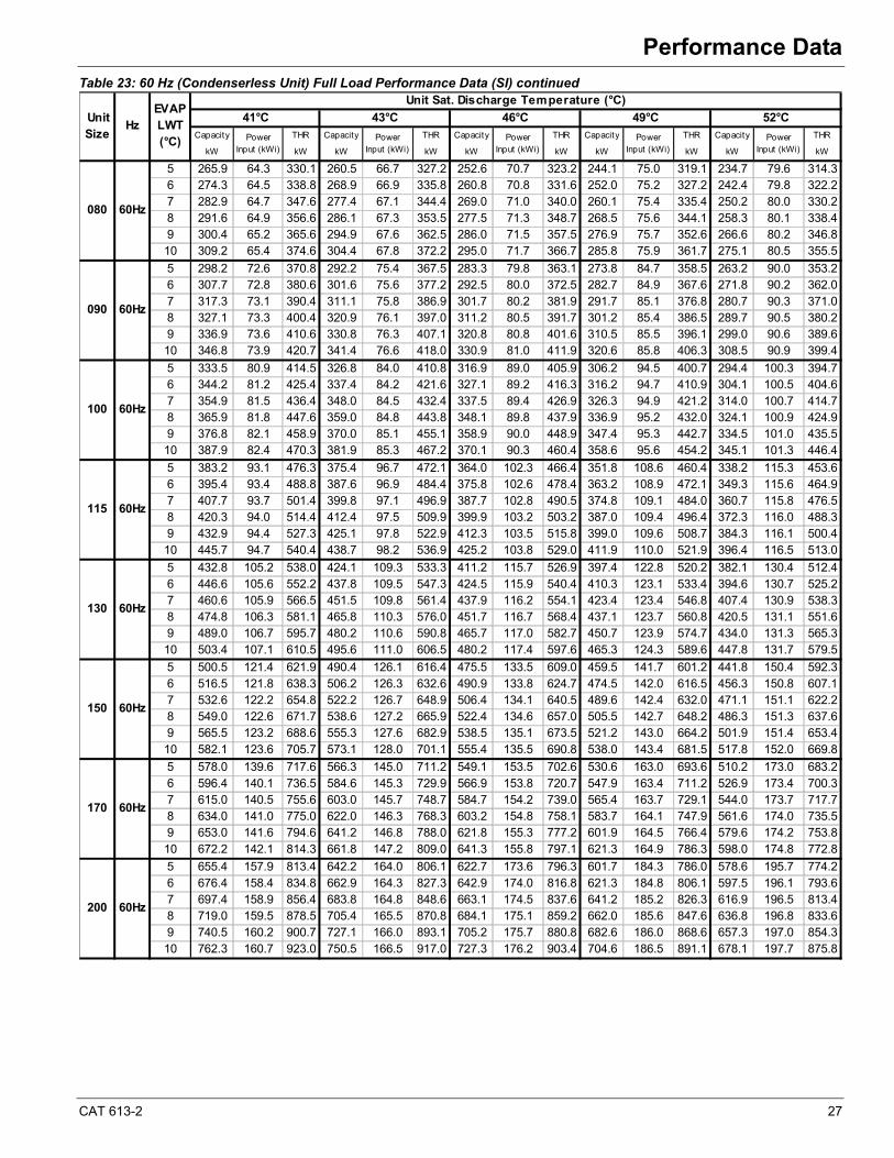
CAT 613-2 27
Performance Data
Table 23: 60 Hz (Condenserless Unit) Full Load Performance Data (SI) continued
Capacity THR Capacity THR Capacity THR Capacity THR Capacity THR
kW kW kW kW kW kW kW kW kW kW
5 265.9 64.3 330.1 260.5 66.7 327.2 252.6 70.7 323.2 244.1 75.0 319.1 234.7 79.6 314.36 274.3 64.5 338.8 268.9 66.9 335.8 260.8 70.8 331.6 252.0 75.2 327.2 242.4 79.8 322.27 282.9 64.7 347.6 277.4 67.1 344.4 269.0 71.0 340.0 260.1 75.4 335.4 250.2 80.0 330.28 291.6 64.9 356.6 286.1 67.3 353.5 277.5 71.3 348.7 268.5 75.6 344.1 258.3 80.1 338.49 300.4 65.2 365.6 294.9 67.6 362.5 286.0 71.5 357.5 276.9 75.7 352.6 266.6 80.2 346.810 309.2 65.4 374.6 304.4 67.8 372.2 295.0 71.7 366.7 285.8 75.9 361.7 275.1 80.5 355.5
5 298.2 72.6 370.8 292.2 75.4 367.5 283.3 79.8 363.1 273.8 84.7 358.5 263.2 90.0 353.26 307.7 72.8 380.6 301.6 75.6 377.2 292.5 80.0 372.5 282.7 84.9 367.6 271.8 90.2 362.07 317.3 73.1 390.4 311.1 75.8 386.9 301.7 80.2 381.9 291.7 85.1 376.8 280.7 90.3 371.08 327.1 73.3 400.4 320.9 76.1 397.0 311.2 80.5 391.7 301.2 85.4 386.5 289.7 90.5 380.29 336.9 73.6 410.6 330.8 76.3 407.1 320.8 80.8 401.6 310.5 85.5 396.1 299.0 90.6 389.610 346.8 73.9 420.7 341.4 76.6 418.0 330.9 81.0 411.9 320.6 85.8 406.3 308.5 90.9 399.4
5 333.5 80.9 414.5 326.8 84.0 410.8 316.9 89.0 405.9 306.2 94.5 400.7 294.4 100.3 394.76 344.2 81.2 425.4 337.4 84.2 421.6 327.1 89.2 416.3 316.2 94.7 410.9 304.1 100.5 404.67 354.9 81.5 436.4 348.0 84.5 432.4 337.5 89.4 426.9 326.3 94.9 421.2 314.0 100.7 414.78 365.9 81.8 447.6 359.0 84.8 443.8 348.1 89.8 437.9 336.9 95.2 432.0 324.1 100.9 424.99 376.8 82.1 458.9 370.0 85.1 455.1 358.9 90.0 448.9 347.4 95.3 442.7 334.5 101.0 435.510 387.9 82.4 470.3 381.9 85.3 467.2 370.1 90.3 460.4 358.6 95.6 454.2 345.1 101.3 446.4
5 383.2 93.1 476.3 375.4 96.7 472.1 364.0 102.3 466.4 351.8 108.6 460.4 338.2 115.3 453.66 395.4 93.4 488.8 387.6 96.9 484.4 375.8 102.6 478.4 363.2 108.9 472.1 349.3 115.6 464.97 407.7 93.7 501.4 399.8 97.1 496.9 387.7 102.8 490.5 374.8 109.1 484.0 360.7 115.8 476.58 420.3 94.0 514.4 412.4 97.5 509.9 399.9 103.2 503.2 387.0 109.4 496.4 372.3 116.0 488.39 432.9 94.4 527.3 425.1 97.8 522.9 412.3 103.5 515.8 399.0 109.6 508.7 384.3 116.1 500.410 445.7 94.7 540.4 438.7 98.2 536.9 425.2 103.8 529.0 411.9 110.0 521.9 396.4 116.5 513.0
5 432.8 105.2 538.0 424.1 109.3 533.3 411.2 115.7 526.9 397.4 122.8 520.2 382.1 130.4 512.46 446.6 105.6 552.2 437.8 109.5 547.3 424.5 115.9 540.4 410.3 123.1 533.4 394.6 130.7 525.27 460.6 105.9 566.5 451.5 109.8 561.4 437.9 116.2 554.1 423.4 123.4 546.8 407.4 130.9 538.38 474.8 106.3 581.1 465.8 110.3 576.0 451.7 116.7 568.4 437.1 123.7 560.8 420.5 131.1 551.69 489.0 106.7 595.7 480.2 110.6 590.8 465.7 117.0 582.7 450.7 123.9 574.7 434.0 131.3 565.310 503.4 107.1 610.5 495.6 111.0 606.5 480.2 117.4 597.6 465.3 124.3 589.6 447.8 131.7 579.5
5 500.5 121.4 621.9 490.4 126.1 616.4 475.5 133.5 609.0 459.5 141.7 601.2 441.8 150.4 592.36 516.5 121.8 638.3 506.2 126.3 632.6 490.9 133.8 624.7 474.5 142.0 616.5 456.3 150.8 607.17 532.6 122.2 654.8 522.2 126.7 648.9 506.4 134.1 640.5 489.6 142.4 632.0 471.1 151.1 622.28 549.0 122.6 671.7 538.6 127.2 665.9 522.4 134.6 657.0 505.5 142.7 648.2 486.3 151.3 637.69 565.5 123.2 688.6 555.3 127.6 682.9 538.5 135.1 673.5 521.2 143.0 664.2 501.9 151.4 653.410 582.1 123.6 705.7 573.1 128.0 701.1 555.4 135.5 690.8 538.0 143.4 681.5 517.8 152.0 669.8
5 578.0 139.6 717.6 566.3 145.0 711.2 549.1 153.5 702.6 530.6 163.0 693.6 510.2 173.0 683.26 596.4 140.1 736.5 584.6 145.3 729.9 566.9 153.8 720.7 547.9 163.4 711.2 526.9 173.4 700.37 615.0 140.5 755.6 603.0 145.7 748.7 584.7 154.2 739.0 565.4 163.7 729.1 544.0 173.7 717.78 634.0 141.0 775.0 622.0 146.3 768.3 603.2 154.8 758.1 583.7 164.1 747.9 561.6 174.0 735.59 653.0 141.6 794.6 641.2 146.8 788.0 621.8 155.3 777.2 601.9 164.5 766.4 579.6 174.2 753.810 672.2 142.1 814.3 661.8 147.2 809.0 641.3 155.8 797.1 621.3 164.9 786.3 598.0 174.8 772.8
5 655.4 157.9 813.4 642.2 164.0 806.1 622.7 173.6 796.3 601.7 184.3 786.0 578.6 195.7 774.26 676.4 158.4 834.8 662.9 164.3 827.3 642.9 174.0 816.8 621.3 184.8 806.1 597.5 196.1 793.67 697.4 158.9 856.4 683.8 164.8 848.6 663.1 174.5 837.6 641.2 185.2 826.3 616.9 196.5 813.48 719.0 159.5 878.5 705.4 165.5 870.8 684.1 175.1 859.2 662.0 185.6 847.6 636.8 196.8 833.69 740.5 160.2 900.7 727.1 166.0 893.1 705.2 175.7 880.8 682.6 186.0 868.6 657.3 197.0 854.310 762.3 160.7 923.0 750.5 166.5 917.0 727.3 176.2 903.4 704.6 186.5 891.1 678.1 197.7 875.8
200 60Hz
130 60Hz
150 60Hz
170 60Hz
090 60Hz
100 60Hz
115 60Hz
EVAP LWT (°C)
Unit Sat. Discharge Temperature (°C)
41°C 43°C 46°C 49°C 52°C
Power Input (kWi)
Power Input (kWi)
Power Input (kWi)
080 60Hz
Unit Size
HzPower
Input (kWi)Power
Input (kWi)
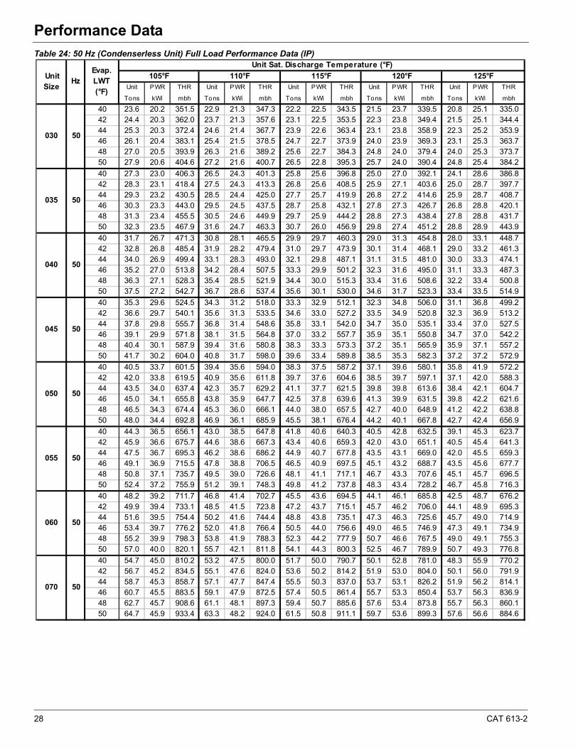
28 CAT 613-2
Performance Data
Table 24: 50 Hz (Condenserless Unit) Full Load Performance Data (IP)
Unit PWR THR Unit PWR THR Unit PWR THR Unit PWR THR Unit PWR THR
Tons kWi mbh Tons kWi mbh Tons kWi mbh Tons kWi mbh Tons kWi mbh
40 23.6 20.2 351.5 22.9 21.3 347.3 22.2 22.5 343.5 21.5 23.7 339.5 20.8 25.1 335.042 24.4 20.3 362.0 23.7 21.3 357.6 23.1 22.5 353.5 22.3 23.8 349.4 21.5 25.1 344.444 25.3 20.3 372.4 24.6 21.4 367.7 23.9 22.6 363.4 23.1 23.8 358.9 22.3 25.2 353.946 26.1 20.4 383.1 25.4 21.5 378.5 24.7 22.7 373.9 24.0 23.9 369.3 23.1 25.3 363.748 27.0 20.5 393.9 26.3 21.6 389.2 25.6 22.7 384.3 24.8 24.0 379.4 24.0 25.3 373.750 27.9 20.6 404.6 27.2 21.6 400.7 26.5 22.8 395.3 25.7 24.0 390.4 24.8 25.4 384.2
40 27.3 23.0 406.3 26.5 24.3 401.3 25.8 25.6 396.8 25.0 27.0 392.1 24.1 28.6 386.842 28.3 23.1 418.4 27.5 24.3 413.3 26.8 25.6 408.5 25.9 27.1 403.6 25.0 28.7 397.744 29.3 23.2 430.5 28.5 24.4 425.0 27.7 25.7 419.9 26.8 27.2 414.6 25.9 28.7 408.746 30.3 23.3 443.0 29.5 24.5 437.5 28.7 25.8 432.1 27.8 27.3 426.7 26.8 28.8 420.148 31.3 23.4 455.5 30.5 24.6 449.9 29.7 25.9 444.2 28.8 27.3 438.4 27.8 28.8 431.750 32.3 23.5 467.9 31.6 24.7 463.3 30.7 26.0 456.9 29.8 27.4 451.2 28.8 28.9 443.9
40 31.7 26.7 471.3 30.8 28.1 465.5 29.9 29.7 460.3 29.0 31.3 454.8 28.0 33.1 448.742 32.8 26.8 485.4 31.9 28.2 479.4 31.0 29.7 473.9 30.1 31.4 468.1 29.0 33.2 461.344 34.0 26.9 499.4 33.1 28.3 493.0 32.1 29.8 487.1 31.1 31.5 481.0 30.0 33.3 474.146 35.2 27.0 513.8 34.2 28.4 507.5 33.3 29.9 501.2 32.3 31.6 495.0 31.1 33.3 487.348 36.3 27.1 528.3 35.4 28.5 521.9 34.4 30.0 515.3 33.4 31.6 508.6 32.2 33.4 500.850 37.5 27.2 542.7 36.7 28.6 537.4 35.6 30.1 530.0 34.6 31.7 523.3 33.4 33.5 514.9
40 35.3 29.6 524.5 34.3 31.2 518.0 33.3 32.9 512.1 32.3 34.8 506.0 31.1 36.8 499.242 36.6 29.7 540.1 35.6 31.3 533.5 34.6 33.0 527.2 33.5 34.9 520.8 32.3 36.9 513.244 37.8 29.8 555.7 36.8 31.4 548.6 35.8 33.1 542.0 34.7 35.0 535.1 33.4 37.0 527.546 39.1 29.9 571.8 38.1 31.5 564.8 37.0 33.2 557.7 35.9 35.1 550.8 34.7 37.0 542.248 40.4 30.1 587.9 39.4 31.6 580.8 38.3 33.3 573.3 37.2 35.1 565.9 35.9 37.1 557.250 41.7 30.2 604.0 40.8 31.7 598.0 39.6 33.4 589.8 38.5 35.3 582.3 37.2 37.2 572.9
40 40.5 33.7 601.5 39.4 35.6 594.0 38.3 37.5 587.2 37.1 39.6 580.1 35.8 41.9 572.242 42.0 33.8 619.5 40.9 35.6 611.8 39.7 37.6 604.6 38.5 39.7 597.1 37.1 42.0 588.344 43.5 34.0 637.4 42.3 35.7 629.2 41.1 37.7 621.5 39.8 39.8 613.6 38.4 42.1 604.746 45.0 34.1 655.8 43.8 35.9 647.7 42.5 37.8 639.6 41.3 39.9 631.5 39.8 42.2 621.648 46.5 34.3 674.4 45.3 36.0 666.1 44.0 38.0 657.5 42.7 40.0 648.9 41.2 42.2 638.850 48.0 34.4 692.8 46.9 36.1 685.9 45.5 38.1 676.4 44.2 40.1 667.8 42.7 42.4 656.9
40 44.3 36.5 656.1 43.0 38.5 647.8 41.8 40.6 640.3 40.5 42.8 632.5 39.1 45.3 623.742 45.9 36.6 675.7 44.6 38.6 667.3 43.4 40.6 659.3 42.0 43.0 651.1 40.5 45.4 641.344 47.5 36.7 695.3 46.2 38.6 686.2 44.9 40.7 677.8 43.5 43.1 669.0 42.0 45.5 659.346 49.1 36.9 715.5 47.8 38.8 706.5 46.5 40.9 697.5 45.1 43.2 688.7 43.5 45.6 677.748 50.8 37.1 735.7 49.5 39.0 726.6 48.1 41.1 717.1 46.7 43.3 707.6 45.1 45.7 696.550 52.4 37.2 755.9 51.2 39.1 748.3 49.8 41.2 737.8 48.3 43.4 728.2 46.7 45.8 716.3
40 48.2 39.2 711.7 46.8 41.4 702.7 45.5 43.6 694.5 44.1 46.1 685.8 42.5 48.7 676.242 49.9 39.4 733.1 48.5 41.5 723.8 47.2 43.7 715.1 45.7 46.2 706.0 44.1 48.9 695.344 51.6 39.5 754.4 50.2 41.6 744.4 48.8 43.8 735.1 47.3 46.3 725.6 45.7 49.0 714.946 53.4 39.7 776.2 52.0 41.8 766.4 50.5 44.0 756.6 49.0 46.5 746.9 47.3 49.1 734.948 55.2 39.9 798.3 53.8 41.9 788.3 52.3 44.2 777.9 50.7 46.6 767.5 49.0 49.1 755.350 57.0 40.0 820.1 55.7 42.1 811.8 54.1 44.3 800.3 52.5 46.7 789.9 50.7 49.3 776.8
40 54.7 45.0 810.2 53.2 47.5 800.0 51.7 50.0 790.7 50.1 52.8 781.0 48.3 55.9 770.242 56.7 45.2 834.5 55.1 47.6 824.0 53.6 50.2 814.2 51.9 53.0 804.0 50.1 56.0 791.944 58.7 45.3 858.7 57.1 47.7 847.4 55.5 50.3 837.0 53.7 53.1 826.2 51.9 56.2 814.146 60.7 45.5 883.5 59.1 47.9 872.5 57.4 50.5 861.4 55.7 53.3 850.4 53.7 56.3 836.948 62.7 45.7 908.6 61.1 48.1 897.3 59.4 50.7 885.6 57.6 53.4 873.8 55.7 56.3 860.150 64.7 45.9 933.4 63.3 48.2 924.0 61.5 50.8 911.1 59.7 53.6 899.3 57.6 56.6 884.6
070 50
050 50
055 50
060 50
035 50
040 50
045 50
HzEvap.LWT(°F)
Unit Sat. Discharge Temperature (°F)
105°F
030 50
Unit Size
110°F 115°F 120°F 125°F

CAT 613-2 29
Performance Data
Table 25: 50 Hz (Condenserless Unit) Full Load Performance Data (IP) continued
Unit PWR THR Unit PWR THR Unit PWR THR Unit PWR THR Unit PWR THR
Tons kWi mbh Tons kWi mbh Tons kWi mbh Tons kWi mbh Tons kWi mbh
40 61.9 50.9 916.5 60.1 53.7 904.9 58.4 56.6 894.5 56.6 59.8 883.5 54.6 63.2 871.242 64.1 51.1 943.9 62.4 53.8 932.1 60.6 56.7 920.9 58.7 60.0 909.5 56.6 63.4 895.844 66.4 51.3 971.3 64.5 53.9 958.6 62.7 56.9 946.7 60.8 60.1 934.5 58.7 63.5 920.946 68.7 51.5 999.4 66.8 54.2 986.9 65.0 57.1 974.4 63.0 60.3 962.0 60.8 63.6 946.748 70.9 51.7 1027.8 69.1 54.4 1015.0 67.2 57.3 1001.8 65.2 60.4 988.4 63.0 63.7 973.050 73.2 51.9 1055.9 71.6 54.6 1045.3 69.5 57.5 1030.6 67.5 60.6 1017.3 65.2 64.0 1000.6
40 69.4 57.5 1029.4 67.5 60.6 1016.5 65.6 63.9 1004.8 63.5 67.5 992.6 61.3 71.4 979.042 71.9 57.7 1060.1 70.0 60.8 1047.0 68.0 64.1 1034.5 65.9 67.7 1021.8 63.5 71.6 1006.544 74.4 57.9 1090.9 72.4 60.9 1076.7 70.4 64.2 1063.5 68.2 67.9 1049.9 65.8 71.8 1034.746 77.0 58.1 1122.4 75.0 61.2 1108.5 72.9 64.5 1094.5 70.7 68.1 1080.6 68.2 71.9 1063.648 79.6 58.4 1154.2 77.5 61.4 1140.0 75.4 64.7 1125.2 73.1 68.2 1110.3 70.6 72.0 1093.150 82.1 58.6 1185.7 80.3 61.6 1173.9 78.0 64.9 1157.5 75.8 68.5 1142.7 73.1 72.3 1124.1
40 77.7 64.1 1150.7 75.5 67.6 1136.2 73.3 71.3 1123.1 71.0 75.3 1109.4 68.5 79.6 1094.142 80.5 64.3 1185.1 78.3 67.8 1170.3 76.1 71.4 1156.4 73.7 75.5 1142.0 71.0 79.8 1124.944 83.3 64.6 1219.5 81.0 67.9 1203.5 78.7 71.6 1188.7 76.3 75.7 1173.5 73.6 80.0 1156.446 86.1 64.8 1254.7 83.9 68.2 1239.1 81.5 71.9 1223.4 79.1 75.9 1207.9 76.3 80.2 1188.848 89.0 65.1 1290.3 86.7 68.5 1274.4 84.3 72.2 1257.8 81.8 76.1 1241.1 79.0 80.2 1221.750 91.9 65.4 1325.6 89.8 68.7 1312.3 87.2 72.4 1293.9 84.7 76.3 1277.3 81.8 80.6 1256.4
40 89.2 73.7 1322.2 86.7 77.7 1305.5 84.2 82.0 1290.6 81.6 86.6 1274.8 78.7 91.5 1257.242 92.4 74.0 1361.7 89.9 77.9 1344.7 87.4 82.2 1328.7 84.7 86.8 1312.3 81.6 91.8 1292.744 95.7 74.2 1401.2 93.0 78.1 1382.9 90.4 82.3 1365.9 87.6 87.0 1348.4 84.6 92.0 1328.846 99.0 74.5 1441.7 96.3 78.5 1423.8 93.6 82.7 1405.7 90.8 87.3 1387.9 87.6 92.2 1366.048 102.3 74.9 1482.6 99.6 78.8 1464.3 96.8 83.0 1445.2 94.0 87.5 1426.1 90.8 92.3 1403.950 105.6 75.2 1523.1 103.2 79.0 1507.9 100.2 83.3 1486.8 97.3 87.8 1467.6 94.0 92.6 1443.7
40 100.8 83.3 1493.7 97.9 87.9 1474.9 95.2 92.7 1458.0 92.2 97.9 1440.2 88.9 103.5 1420.442 104.4 83.6 1538.3 101.6 88.1 1519.2 98.7 92.9 1501.1 95.6 98.2 1482.5 92.2 103.8 1460.444 108.0 83.9 1582.9 105.1 88.3 1562.3 102.1 93.1 1543.1 99.0 98.4 1523.4 95.5 104.0 1501.246 111.8 84.2 1628.7 108.8 88.7 1608.4 105.8 93.5 1588.1 102.6 98.7 1568.0 99.0 104.2 1543.248 115.5 84.7 1674.8 112.5 89.0 1654.2 109.4 93.8 1632.7 106.1 98.9 1611.1 102.5 104.3 1586.050 119.2 85.0 1720.6 116.6 89.3 1703.4 113.2 94.1 1679.6 110.0 99.2 1658.0 106.1 104.7 1631.0
40 116.5 96.1 1726.5 113.2 101.4 1704.8 110.0 106.9 1685.2 106.6 112.9 1664.6 102.9 119.4 1641.642 120.7 96.5 1778.2 117.4 101.6 1756.0 114.1 107.2 1735.1 110.6 113.3 1713.5 106.6 119.8 1687.944 124.9 96.8 1829.8 121.5 101.9 1805.9 118.1 107.4 1783.6 114.5 113.5 1760.7 110.5 120.0 1735.146 129.3 97.2 1882.7 125.8 102.4 1859.2 122.3 107.9 1835.6 118.6 113.9 1812.3 114.5 120.2 1783.748 133.6 97.7 1936.0 130.1 102.7 1912.1 126.5 108.2 1887.2 122.7 114.1 1862.2 118.5 120.4 1833.150 137.9 98.0 1989.0 134.8 103.1 1969.0 130.9 108.6 1941.5 127.2 114.5 1916.5 122.7 120.8 1885.1
40 134.6 110.5 1992.2 130.8 116.6 1967.0 127.1 123.0 1944.3 123.1 129.9 1920.3 118.8 137.3 1893.742 139.4 111.0 2051.8 135.6 116.9 2026.1 131.8 123.2 2001.8 127.7 130.3 1976.9 123.1 137.7 1947.244 144.3 111.4 2111.4 140.3 117.2 2083.7 136.4 123.5 2057.9 132.2 130.5 2031.4 127.6 138.0 2001.746 149.3 111.8 2172.5 145.3 117.7 2145.3 141.2 124.1 2118.0 137.0 131.0 2091.0 132.2 138.3 2057.848 154.2 112.3 2234.1 150.3 118.1 2206.4 146.1 124.5 2177.5 141.7 131.2 2148.6 136.9 138.4 2114.950 159.2 112.7 2295.2 155.6 118.5 2272.1 151.2 124.9 2240.2 146.8 131.7 2211.2 141.7 139.0 2174.9
40 152.6 125.0 2258.1 148.3 131.9 2229.4 144.1 139.1 2203.6 139.6 146.9 2176.4 134.7 155.3 2146.142 158.1 125.5 2325.6 153.8 132.2 2296.5 149.4 139.4 2268.9 144.8 147.3 2240.5 139.6 155.8 2206.744 163.6 126.0 2393.2 159.1 132.5 2361.8 154.7 139.7 2332.4 149.9 147.7 2302.3 144.7 156.1 2268.646 169.3 126.4 2462.5 164.8 133.1 2431.6 160.1 140.3 2400.5 155.4 148.1 2369.9 149.9 156.4 2332.148 174.9 127.0 2532.3 170.4 133.6 2500.9 165.6 140.8 2468.1 160.7 148.4 2435.2 155.2 156.5 2396.950 180.5 127.5 2601.7 176.5 134.1 2575.4 171.4 141.3 2539.1 166.5 148.9 2506.2 160.7 157.2 2465.0
200 50
130 50
150 50
170 50
090 50
100 50
115 50
080 50
115°F 120°F 125°F Unit Size
HzEvap.LWT(°F)
Unit Sat. Discharge Temperature (°F)
105°F 110°F
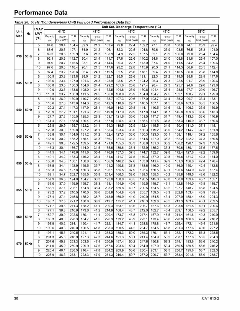
30 CAT 613-2
Performance Data
Table 26: 50 Hz (Condenserless Unit) Full Load Performance Data (SI)
Capacity THR Capacity THR Capacity THR Capacity THR Capacity THR
kW kW kW kW kW kW kW kW kW kW
5 84.0 20.4 104.4 82.3 21.2 103.4 79.8 22.4 102.2 77.1 23.8 100.9 74.1 25.3 99.46 86.6 20.5 107.1 84.9 21.2 106.1 82.3 22.5 104.8 79.6 23.9 103.5 76.5 25.3 101.97 89.3 20.5 109.9 87.6 21.3 108.9 84.9 22.5 107.5 82.1 23.9 106.0 79.0 25.4 104.48 92.1 20.6 112.7 90.4 21.4 111.7 87.6 22.6 110.2 84.8 24.0 108.8 81.6 25.4 107.09 94.9 20.7 115.5 93.1 21.4 114.6 90.3 22.7 113.0 87.4 24.0 111.5 84.2 25.4 109.610 97.6 20.8 118.4 96.1 21.5 117.6 93.2 22.8 115.9 90.3 24.1 114.3 86.9 25.5 112.4
5 97.4 23.2 120.6 95.4 24.1 119.5 92.5 25.6 118.1 89.4 27.1 116.5 86.0 28.8 114.86 100.5 23.3 123.8 98.5 24.2 122.7 95.5 25.6 121.1 92.3 27.2 119.5 88.8 28.9 117.67 103.6 23.4 127.0 101.6 24.3 125.9 98.5 25.7 124.2 95.3 27.3 122.5 91.7 28.9 120.68 106.8 23.5 130.3 104.8 24.4 129.2 101.6 25.8 127.4 98.4 27.3 125.7 94.6 29.0 123.69 110.0 23.6 133.6 108.0 24.4 132.5 104.8 25.9 130.6 101.4 27.4 128.8 97.7 29.0 126.710 113.3 23.7 136.9 111.5 24.5 136.0 108.0 25.9 134.0 104.7 27.5 132.1 100.7 29.1 129.9
5 113.0 26.9 139.9 110.7 28.0 138.7 107.3 29.6 137.0 103.7 31.4 135.2 99.7 33.4 133.16 116.6 27.0 143.6 114.3 28.0 142.3 110.8 29.7 140.5 107.1 31.5 138.6 103.0 33.5 136.57 120.2 27.1 147.3 117.9 28.1 146.0 114.3 29.8 144.1 110.5 31.6 142.1 106.3 33.5 139.98 123.9 27.2 151.1 121.6 28.2 149.8 117.9 29.9 147.8 114.1 31.7 145.8 109.8 33.6 143.39 127.7 27.3 155.0 125.3 28.3 153.7 121.6 30.0 151.5 117.7 31.7 149.4 113.3 33.6 146.910 131.4 27.4 158.8 129.4 28.4 157.8 125.4 30.1 155.4 121.5 31.8 153.3 116.9 33.7 150.6
5 125.8 29.9 155.7 123.2 31.1 154.3 119.5 32.9 152.4 115.5 34.9 150.4 111.0 37.1 148.16 129.8 30.0 159.8 127.2 31.1 158.4 123.4 33.0 156.3 119.2 35.0 154.2 114.7 37.2 151.87 133.8 30.1 164.0 131.2 31.2 162.4 127.3 33.0 160.3 123.0 35.1 158.1 118.4 37.2 155.68 138.0 30.2 168.2 135.4 31.3 166.7 131.3 33.2 164.5 127.0 35.2 162.2 122.2 37.3 159.59 142.1 30.3 172.5 139.5 31.4 171.0 135.3 33.3 168.6 131.0 35.2 166.2 126.1 37.3 163.510 146.3 30.4 176.7 144.0 31.5 175.6 139.6 33.4 172.9 135.2 35.3 170.6 130.1 37.5 167.6
5 144.5 34.1 178.6 141.6 35.4 176.9 137.3 37.5 174.7 132.7 39.8 172.4 127.6 42.2 169.86 149.1 34.2 183.3 146.2 35.4 181.6 141.7 37.5 179.3 137.0 39.8 176.8 131.7 42.3 174.07 153.8 34.3 188.1 150.8 35.5 186.3 146.2 37.6 183.8 141.4 39.9 181.3 136.0 42.4 178.48 158.5 34.4 192.9 155.5 35.7 191.2 150.8 37.8 188.6 146.0 40.0 186.0 140.4 42.4 182.89 163.3 34.5 197.8 160.3 35.8 196.1 155.5 37.9 193.4 150.5 40.1 190.6 144.9 42.5 187.410 168.1 34.7 202.7 165.5 35.9 201.4 160.3 38.0 198.3 155.3 40.2 195.6 149.5 42.6 192.2
5 157.9 36.8 194.8 154.7 38.3 193.0 150.0 40.5 190.5 145.0 43.0 188.0 139.4 45.7 185.16 163.0 37.0 199.9 159.7 38.3 198.1 154.9 40.6 195.5 149.7 43.1 192.8 144.0 45.8 189.77 168.1 37.1 205.1 164.8 38.4 203.2 159.8 40.7 200.5 154.5 43.2 197.7 148.7 45.8 194.58 173.2 37.2 210.5 170.0 38.6 208.6 164.8 40.9 205.7 159.5 43.3 202.8 153.4 45.9 199.49 178.4 37.4 215.8 175.2 38.7 213.9 169.9 41.0 210.9 164.5 43.4 207.9 158.4 46.0 204.310 183.7 37.5 221.2 180.8 38.9 219.7 175.2 41.1 216.3 169.8 43.5 213.3 163.4 46.1 209.5
5 171.7 39.6 211.3 168.2 41.1 209.3 163.1 43.6 206.7 157.6 46.3 203.8 151.5 49.1 200.66 177.1 39.8 216.9 173.6 41.2 214.9 168.4 43.7 212.0 162.7 46.4 209.1 156.5 49.2 205.77 182.7 39.9 222.6 179.1 41.4 220.4 173.7 43.8 217.4 167.9 46.5 214.4 161.6 49.3 210.98 188.3 40.0 228.3 184.7 41.5 226.3 179.2 43.9 223.1 173.4 46.6 220.0 166.8 49.4 216.29 193.9 40.2 234.1 190.4 41.7 232.1 184.7 44.1 228.8 178.8 46.7 225.4 172.1 49.4 221.610 199.6 40.3 240.0 196.5 41.8 238.3 190.5 44.2 234.7 184.5 46.8 231.3 177.6 49.6 227.2
5 195.1 45.5 240.5 191.1 47.2 238.3 185.3 50.0 235.3 179.1 53.1 232.1 172.2 56.3 228.56 201.3 45.6 246.9 197.3 47.3 244.6 191.3 50.1 241.4 184.9 53.2 238.1 177.8 56.5 234.37 207.6 45.8 253.3 203.5 47.4 250.9 197.4 50.2 247.6 190.8 53.3 244.1 183.6 56.6 240.28 214.0 45.9 259.9 209.9 47.6 257.6 203.6 50.4 254.0 197.0 53.4 250.5 189.5 56.6 246.29 220.4 46.1 266.5 216.4 47.8 264.2 209.9 50.6 260.4 203.1 53.5 256.7 195.6 56.7 252.310 226.9 46.3 273.1 223.3 47.9 271.3 216.4 50.7 267.2 209.7 53.7 263.4 201.8 56.9 258.7
070 50Hz
050 50Hz
055 50Hz
060 50Hz
035 50Hz
040 50Hz
045 50Hz
EVAP LWT (°C)
Unit Sat. Discharge Temperature (°C)
41°C 43°C 46°C 49°C 52°C
Power Input (kWi)
030 50Hz
Unit Size
HzPower
Input (kWi)Power
Input (kWi)Power
Input (kWi)Power
Input (kWi)
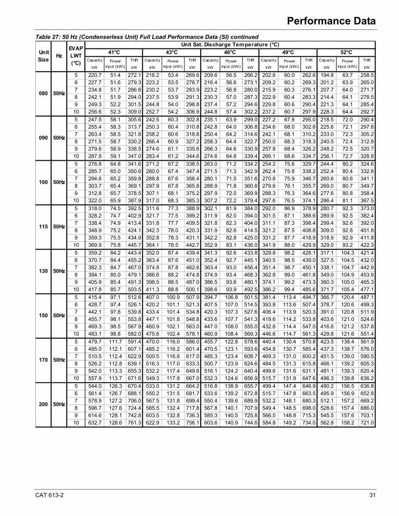
CAT 613-2 31
Performance Data
Table 27: 50 Hz (Condenserless Unit) Full Load Performance Data (SI) continued
Capacity THR Capacity THR Capacity THR Capacity THR Capacity THR
kW kW kW kW kW kW kW kW kW kW
5 220.7 51.4 272.1 216.2 53.4 269.6 209.6 56.5 266.2 202.6 60.0 262.6 194.8 63.7 258.56 227.7 51.6 279.3 223.2 53.5 276.7 216.4 56.6 273.1 209.2 60.2 269.3 201.2 63.9 265.07 234.8 51.7 286.6 230.2 53.7 283.9 223.2 56.8 280.0 215.9 60.3 276.1 207.7 64.0 271.78 242.1 51.9 294.0 237.5 53.9 291.3 230.3 57.0 287.3 222.9 60.4 283.3 214.4 64.1 278.59 249.3 52.2 301.5 244.8 54.0 298.8 237.4 57.2 294.6 229.8 60.6 290.4 221.3 64.1 285.410 256.6 52.3 309.0 252.7 54.2 306.9 244.8 57.4 302.2 237.2 60.7 297.9 228.3 64.4 292.7
5 247.5 58.1 305.6 242.5 60.3 302.8 235.1 63.9 299.0 227.2 67.8 295.0 218.5 72.0 290.46 255.4 58.3 313.7 250.3 60.4 310.8 242.8 64.0 306.8 234.6 68.0 302.6 225.6 72.1 297.87 263.4 58.5 321.8 258.2 60.6 318.8 250.4 64.2 314.6 242.1 68.1 310.2 233.0 72.3 305.28 271.5 58.7 330.2 266.4 60.9 327.2 258.3 64.4 322.7 250.0 68.3 318.3 240.5 72.4 312.89 279.6 58.9 338.5 274.6 61.1 335.6 266.3 64.6 330.9 257.8 68.4 326.2 248.2 72.5 320.710 287.9 59.1 347.0 283.4 61.2 344.6 274.6 64.8 339.4 266.1 68.6 334.7 256.1 72.7 328.8
5 276.8 64.8 341.6 271.2 67.2 338.5 263.0 71.2 334.2 254.2 75.6 329.7 244.4 80.2 324.66 285.7 65.0 350.6 280.0 67.4 347.4 271.5 71.3 342.9 262.4 75.8 338.2 252.4 80.4 332.87 294.6 65.2 359.8 288.8 67.6 356.4 280.1 71.5 351.6 270.8 75.9 346.7 260.6 80.6 341.18 303.7 65.4 369.1 297.9 67.8 365.8 288.9 71.8 360.8 279.6 76.1 355.7 269.0 80.7 349.79 312.8 65.7 378.5 307.1 68.1 375.2 297.9 72.0 369.9 288.3 76.3 364.6 277.6 80.8 358.410 322.0 65.9 387.9 317.0 68.3 385.3 307.2 72.2 379.4 297.6 76.5 374.1 286.4 81.1 367.5
5 318.0 74.5 392.5 311.6 77.3 388.9 302.1 81.9 384.0 292.0 86.9 378.9 280.7 92.3 373.06 328.2 74.7 402.9 321.7 77.5 399.2 311.9 82.0 394.0 301.5 87.1 388.6 289.9 92.5 382.47 338.4 74.9 413.4 331.8 77.7 409.5 321.8 82.3 404.0 311.1 87.3 398.4 299.4 92.6 392.08 348.9 75.2 424.1 342.3 78.0 420.3 331.9 82.6 414.5 321.2 87.5 408.8 309.0 92.8 401.89 359.3 75.5 434.9 352.8 78.3 431.1 342.2 82.8 425.0 331.2 87.7 418.9 318.9 92.9 411.810 369.9 75.8 445.7 364.1 78.5 442.7 352.9 83.1 436.0 341.9 88.0 429.9 329.0 93.2 422.3
5 359.2 84.2 443.4 352.0 87.4 439.4 341.3 92.6 433.8 329.8 98.2 428.1 317.1 104.3 421.46 370.7 84.4 455.2 363.4 87.6 451.0 352.4 92.7 445.1 340.5 98.5 439.0 327.5 104.5 432.07 382.3 84.7 467.0 374.8 87.8 462.6 363.4 93.0 456.4 351.4 98.7 450.1 338.1 104.7 442.98 394.1 85.0 479.1 386.6 88.2 474.8 374.9 93.4 468.3 362.8 99.0 461.8 349.0 104.9 453.99 405.9 85.4 491.3 398.5 88.5 487.0 386.5 93.6 480.1 374.1 99.2 473.3 360.3 105.0 465.310 417.8 85.7 503.5 411.3 88.8 500.1 398.6 93.9 492.5 386.2 99.4 485.6 371.7 105.4 477.1
5 415.4 97.1 512.6 407.0 100.9 507.9 394.7 106.8 501.5 381.4 113.4 494.7 366.7 120.4 487.16 428.7 97.4 526.1 420.2 101.1 521.3 407.5 107.0 514.5 393.8 113.6 507.4 378.7 120.6 499.37 442.1 97.8 539.8 433.4 101.4 534.8 420.3 107.3 527.6 406.4 113.9 520.3 391.0 120.8 511.98 455.7 98.1 553.8 447.1 101.8 548.8 433.6 107.7 541.3 419.6 114.2 533.8 403.6 121.0 524.69 469.3 98.5 567.9 460.9 102.1 563.0 447.0 108.0 555.0 432.6 114.4 547.0 416.6 121.2 537.810 483.1 98.8 582.0 475.6 102.4 578.1 460.9 108.4 569.3 446.6 114.7 561.3 429.8 121.6 551.4
5 479.7 111.7 591.4 470.0 116.0 586.0 455.7 122.8 578.6 440.4 130.4 570.8 423.5 138.4 561.96 495.0 112.1 607.1 485.2 116.2 601.4 470.5 123.1 593.6 454.8 130.7 585.4 437.3 138.7 576.07 510.5 112.4 622.9 500.5 116.6 617.0 485.3 123.4 608.7 469.3 131.0 600.2 451.5 139.0 590.58 526.2 112.8 639.1 516.3 117.0 633.3 500.7 123.9 624.6 484.5 131.3 615.8 466.1 139.2 605.39 542.0 113.3 655.3 532.2 117.4 649.6 516.1 124.2 640.4 499.6 131.6 631.1 481.1 139.3 620.410 557.9 113.7 671.6 549.3 117.8 667.0 532.3 124.6 656.9 515.7 131.9 647.6 496.3 139.8 636.2
5 544.0 126.3 670.4 533.0 131.2 664.2 516.8 138.9 655.7 499.4 147.4 646.9 480.2 156.5 636.86 561.4 126.7 688.1 550.2 131.5 681.7 533.6 139.2 672.8 515.7 147.8 663.5 495.9 156.9 652.87 578.9 127.2 706.0 567.5 131.8 699.4 550.4 139.6 689.9 532.2 148.1 680.3 512.1 157.2 669.28 596.7 127.6 724.4 585.5 132.4 717.8 567.8 140.1 707.9 549.4 148.5 698.0 528.6 157.4 686.09 614.6 128.1 742.8 603.5 132.8 736.3 585.3 140.5 725.8 566.5 148.8 715.3 545.5 157.6 703.110 632.7 128.6 761.3 622.9 133.2 756.1 603.6 140.9 744.6 584.8 149.2 734.0 562.8 158.2 721.0
200 50Hz
130 50Hz
150 50Hz
170 50Hz
090 50Hz
100 50Hz
115 50Hz
EVAP LWT (°C)
Unit Sat. Discharge Temperature (°C)
41°C 43°C 46°C 49°C 52°C
Power Input (kWi)
080 50Hz
Unit Size
HzPower
Input (kWi)Power
Input (kWi)Power
Input (kWi)Power
Input (kWi)
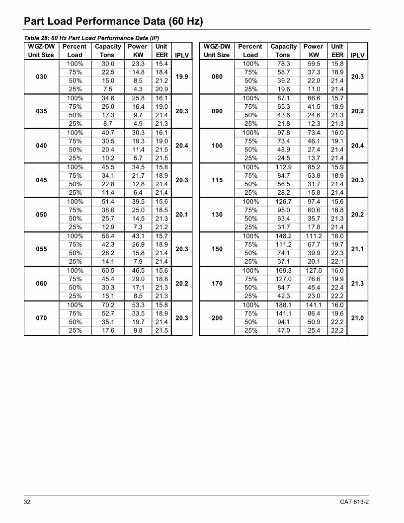
32 CAT 613-2
Part Load Performance Data (60 Hz)Part Load Performance Data (60 Hz)
Table 28: 60 Hz Part Load Performance Data (IP)
WGZ-DW Percent Capacity Power Unit WGZ-DW Percent Capacity Power Unit Unit Size Load Tons KW EER Unit Size Load Tons KW EER
100% 30.0 23.3 15.4 100% 78.3 59.5 15.875% 22.5 14.8 18.4 75% 58.7 37.3 18.950% 15.0 8.5 21.2 50% 39.2 22.0 21.425% 7.5 4.3 20.9 25% 19.6 11.0 21.4
100% 34.6 25.8 16.1 100% 87.1 66.6 15.775% 26.0 16.4 19.0 75% 65.3 41.5 18.950% 17.3 9.7 21.4 50% 43.6 24.6 21.325% 8.7 4.9 21.3 25% 21.8 12.3 21.3
100% 40.7 30.3 16.1 100% 97.8 73.4 16.075% 30.5 19.3 19.0 75% 73.4 46.1 19.150% 20.4 11.4 21.5 50% 48.9 27.4 21.425% 10.2 5.7 21.5 25% 24.5 13.7 21.4
100% 45.5 34.5 15.8 100% 112.9 85.2 15.975% 34.1 21.7 18.9 75% 84.7 53.8 18.950% 22.8 12.8 21.4 50% 56.5 31.7 21.425% 11.4 6.4 21.4 25% 28.2 15.8 21.4
100% 51.4 39.5 15.6 100% 126.7 97.4 15.675% 38.6 25.0 18.5 75% 95.0 60.6 18.850% 25.7 14.5 21.3 50% 63.4 35.7 21.325% 12.9 7.3 21.2 25% 31.7 17.8 21.4
100% 56.4 43.1 15.7 100% 148.2 111.2 16.075% 42.3 26.9 18.9 75% 111.2 67.7 19.750% 28.2 15.8 21.4 50% 74.1 39.9 22.325% 14.1 7.9 21.4 25% 37.1 20.1 22.1
100% 60.5 46.5 15.6 100% 169.3 127.0 16.075% 45.4 29.0 18.8 75% 127.0 76.6 19.950% 30.3 17.1 21.3 50% 84.7 45.4 22.425% 15.1 8.5 21.3 25% 42.3 23.0 22.2
100% 70.2 53.3 15.8 100% 188.1 141.1 16.075% 52.7 33.5 18.9 75% 141.1 86.4 19.650% 35.1 19.7 21.4 50% 94.1 50.9 22.225% 17.6 9.8 21.5 25% 47.0 25.4 22.2
20.3
20.2
20.4
20.3
IPLVIPLV
20.3
20.2
21.1
20.1
20.3
080
090
100
19.9
20.3
20.4
060
070 20.3
21.3
21.0
045
055
050
170
200
20.2
030
035
040
115
130
150
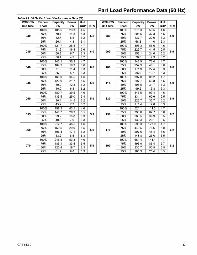
CAT 613-2 33
Part Load Performance Data (60 Hz)
Table 29: 60 Hz Part Load Performance Data (SI) WGZ-DW Percent Capacity Power Unit WGZ-DW Percent Capacity Power Unit Unit Size Load kW kW COP Unit Size Load kW kW COP
100% 105.5 23.3 4.5 100% 275.3 59.5 4.675% 79.1 14.8 5.3 75% 206.5 37.3 5.550% 52.7 8.5 6.2 50% 137.7 22.0 6.325% 26.4 4.3 6.1 25% 68.8 11.0 6.3
100% 121.7 25.8 4.7 100% 306.3 66.6 4.675% 91.2 16.4 5.6 75% 229.7 41.5 5.550% 60.8 9.7 6.3 50% 153.1 24.6 6.225% 30.4 4.9 6.2 25% 76.6 12.3 6.2
100% 143.1 30.3 4.7 100% 343.9 73.4 4.775% 107.3 19.3 5.6 75% 257.9 46.1 5.650% 71.6 11.4 6.3 50% 171.9 27.4 6.325% 35.8 5.7 6.3 25% 86.0 13.7 6.3
100% 160.0 34.5 4.6 100% 397.0 85.2 4.775% 120.0 21.7 5.5 75% 297.7 53.8 5.550% 80.0 12.8 6.2 50% 198.5 31.7 6.325% 40.0 6.4 6.2 25% 99.2 15.8 6.3
100% 180.7 39.5 4.6 100% 445.5 97.4 4.675% 135.5 25.0 5.4 75% 334.1 60.6 5.550% 90.4 14.5 6.2 50% 222.7 35.7 6.225% 45.2 7.3 6.2 25% 111.4 17.8 6.3
100% 198.3 43.1 4.6 100% 521.1 111.2 4.775% 148.7 26.9 5.5 75% 390.8 67.7 5.850% 99.2 15.8 6.3 50% 260.5 39.9 6.525% 49.6 7.9 6.3 25% 130.3 20.1 6.5
100% 212.7 46.5 4.6 100% 595.3 127.0 4.775% 159.5 29.0 5.5 75% 446.5 76.6 5.850% 106.4 17.1 6.2 50% 297.6 45.4 6.625% 53.2 8.5 6.3 25% 148.8 23.0 6.5
100% 246.8 53.3 4.6 100% 661.4 141.1 4.775% 185.1 33.5 5.5 75% 496.0 86.4 5.750% 123.4 19.7 6.3 50% 330.7 50.9 6.525% 61.7 9.8 6.3 25% 165.3 25.4 6.5
070 5.9 200 6.2
050 5.9 130 5.9
055 5.9 150 6.2
060 5.9 170 6.2
5.9
040 6.0 100 6.0
045 5.9 115 5.9
IPLV
030 5.8 080 5.9
035 6.0 090
IPLV

34 CAT 613-2
Part Load Performance Data (50 Hz)Part Load Performance Data (50 Hz)
Table 30: 50 Hz Part Load Performance Data (IP) WGZ-DW Percent Capacity Power Unit WGZ-DW Percent Capacity Power Unit Unit Size Load Tons KW EER Unit Size Load Tons KW EER
100% 24.9 18.6 16.0 100% 65.0 47.6 16.475% 18.7 11.8 18.9 75% 48.7 29.8 19.650% 12.5 6.8 22.0 50% 32.5 17.6 22.225% 6.2 3.4 21.7 25% 16.2 8.8 22.2
100% 28.7 20.6 16.7 100% 72.3 53.3 16.375% 21.5 13.1 19.7 75% 54.2 33.2 19.650% 14.4 7.8 22.2 50% 36.1 19.7 22.025% 7.2 3.9 22.0 25% 18.1 9.8 22.0
100% 33.8 24.2 16.7 100% 81.2 58.7 16.675% 25.3 15.4 19.7 75% 60.9 36.9 19.850% 16.9 9.1 22.2 50% 40.6 21.9 22.225% 8.4 4.6 22.2 25% 20.3 11.0 22.2
100% 37.8 27.6 16.4 100% 93.7 68.2 16.575% 28.3 17.4 19.6 75% 70.3 43.0 19.650% 18.9 10.2 22.1 50% 46.9 25.4 22.225% 9.4 5.1 22.1 25% 23.4 12.6 22.2
100% 42.7 31.6 16.2 100% 105.2 77.9 16.275% 32.0 20.0 19.2 75% 78.9 48.5 19.550% 21.3 11.6 22.1 50% 52.6 28.6 22.125% 10.7 5.8 21.9 25% 26.3 14.2 22.2
100% 46.8 34.5 16.3 100% 123.0 89.0 16.675% 35.1 21.5 19.6 75% 92.3 54.2 20.450% 23.4 12.6 22.2 50% 61.5 31.9 23.125% 11.7 6.3 22.2 25% 30.8 16.1 22.9
100% 50.2 37.2 16.2 100% 140.5 101.6 16.675% 37.7 23.2 19.5 75% 105.4 61.3 20.650% 25.1 13.7 22.0 50% 70.3 36.3 23.225% 12.6 6.8 22.2 25% 35.1 18.4 22.9
100% 58.3 42.6 16.4 100% 156.1 112.9 16.675% 43.7 26.8 19.6 75% 117.1 69.1 20.350% 29.1 15.8 22.2 50% 78.1 40.7 23.025% 14.6 7.8 22.3 25% 39.0 20.3 23.0
070 21.1 200 21.8
050 20.8 130 21.0
055 21.1 150 21.9
060 21.0 170 22.1
035 21.1 090 21.0
040 21.2 100 21.1
045 21.1 115 21.1
IPLV IPLV
030 20.7 080 21.1

CAT 613-2 35
Part Load Performance Data (50 Hz)
Table 31: 50 Hz Part Load Performance Data (SI) WGZ-DW Percent Capacity Power Unit WGZ-DW Percent Capacity Power Unit Unit Size Load kW kW COP Unit Size Load kW kW COP
100% 87.6 18.6 4.7 100% 228.5 47.6 4.875% 65.7 11.8 5.5 75% 171.4 29.8 5.750% 43.8 6.8 6.4 50% 114.3 17.6 6.525% 21.9 3.4 6.4 25% 57.1 8.8 6.5
100% 101.0 20.6 4.9 100% 254.2 53.3 4.875% 75.7 13.1 5.8 75% 190.6 33.2 5.750% 50.5 7.8 6.5 50% 127.1 19.7 6.525% 25.2 3.9 6.4 25% 63.5 9.8 6.5
100% 118.8 24.2 4.9 100% 285.4 58.7 4.975% 89.1 15.4 5.8 75% 214.1 36.9 5.850% 59.4 9.1 6.5 50% 142.7 21.9 6.525% 29.7 4.6 6.5 25% 71.4 11.0 6.5
100% 132.8 27.6 4.8 100% 329.5 68.2 4.875% 99.6 17.4 5.7 75% 247.1 43.0 5.750% 66.4 10.2 6.5 50% 164.7 25.4 6.525% 33.2 5.1 6.5 25% 82.4 12.6 6.5
100% 150.0 31.6 4.7 100% 369.8 77.9 4.775% 112.5 20.0 5.6 75% 277.3 48.5 5.750% 75.0 11.6 6.5 50% 184.9 28.6 6.525% 37.5 5.8 6.4 25% 92.4 14.2 6.5
100% 164.6 34.5 4.8 100% 432.5 89.0 4.975% 123.4 21.5 5.7 75% 324.4 54.2 6.050% 82.3 12.6 6.5 50% 216.3 31.9 6.825% 41.1 6.3 6.5 25% 108.1 16.1 6.7
100% 176.6 37.2 4.7 100% 494.1 101.6 4.975% 132.4 23.2 5.7 75% 370.6 61.3 6.050% 88.3 13.7 6.5 50% 247.0 36.3 6.825% 44.1 6.8 6.5 25% 123.5 18.4 6.7
100% 204.9 42.6 4.8 100% 549.0 112.9 4.975% 153.7 26.8 5.7 75% 411.7 69.1 6.050% 102.4 15.8 6.5 50% 274.5 40.7 6.725% 51.2 7.8 6.5 25% 137.2 20.3 6.8
070 6.2 200 6.4
050 6.1 130 6.1
055 6.2 150 6.4
060 6.1 170 6.5
035 6.2 090 6.2
040 6.2 100 6.2
045 6.2 115 6.2
IPLV IPLV
030 6.1 080 6.2
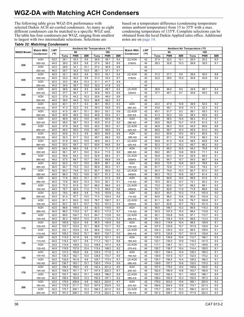
36 CAT 613-2
WGZ-DA with Matching ACH CondensersWGZ-DA with Matching ACH Condensers
The following table gives WGZ-DA performance with selected Daikin ACH air-cooled condensers. As many as eight different condensers can be matched to a specific WGZ unit. The table has four condensers per WGZ, ranging from smallest to largest with two intermediate selections. Selections are
based on a temperature difference (condensing temperature minus ambient temperature) from 15 to 35ºF with a max. condensing temperature of 135ºF. Complete selections can be obtained from the local Daikin Applied sales office. Additional notes are on page 14.
Table 32: Matching Condensers
Tons PWR EER Tons PWR EER Tons PWR EER Tons PWR EER
ACH 42.0 28.1 35.3 9.6 26.6 38.1 8.4 (2) ACH 42 27.4 32.5 10.1 26.0 35.2 8.9
040 AD 44.0 29.0 35.5 9.8 27.4 38.3 8.6 016AS 44 28.3 32.8 10.3 26.8 35.5 9.1
ACH 42.0 28.8 34.1 10.1 27.2 36.9 8.8 42
050 AD 44.0 29.7 34.2 10.4 28.1 37.1 9.1 44
ACH 42.0 32.1 40.0 9.6 30.3 43.1 8.4 (2) ACH 42 31.2 37.7 9.9 29.6 40.5 8.8
040 AD 44.0 33.2 40.2 9.9 31.3 43.4 8.7 016AS 44 32.2 38.0 10.2 30.6 40.8 9.0
ACH 42.0 33.0 38.4 10.3 31.1 41.7 8.9 42
050 AD 44.0 34.0 38.7 10.5 32.2 41.9 9.2 44
ACH 42.0 36.6 46.4 9.5 34.6 49.7 8.4 (2) ACH 42 36.6 46.4 9.5 34.6 49.7 8.4
040 AD 44.0 37.7 46.7 9.7 35.8 50.0 8.6 020AS 44 37.7 46.7 9.7 35.8 50.0 8.6
ACH 42.0 37.8 44.2 10.3 35.6 48.0 8.9 42
050 AD 44.0 39.0 44.5 10.5 36.8 48.2 9.2 44
ACH 42.0 40.1 51.7 9.3 38.1 55.3 8.3 ACH 42 42.2 47.9 10.6 39.9 52.0 9.2
040 AD 44.0 41.3 52.2 9.5 39.3 55.6 8.5 060 AD 44 43.6 48.1 10.9 41.3 52.3 9.5
ACH 42.0 41.5 49.1 10.1 39.3 53.1 8.9 (2) ACH 42 40.1 51.7 9.3 38.1 55.3 8.3
050 AD 44.0 42.9 49.4 10.4 40.6 53.4 9.1 020 AS 44 41.3 52.2 9.5 39.3 55.6 8.5
ACH 42.0 46.9 56.3 10.0 44.5 60.6 8.8 ACH 42 49.0 56.5 10.4 46.3 61.2 9.1
050 AD 44.0 48.5 56.7 10.3 45.9 61.0 9.0 080 AD 44 50.6 56.8 10.7 47.9 61.5 9.3
ACH 42.0 47.9 54.6 10.5 45.2 59.3 9.1 (2) ACH 42 46.9 56.3 10.0 44.5 60.6 8.8
060 AD 44.0 49.4 55.0 10.8 46.7 59.6 9.4 025 AD 44 48.5 56.7 10.3 45.9 61.0 9.0
ACH 42.0 50.8 61.3 9.9 48.0 65.8 8.8 ACH 42 53.2 60.8 10.5 50.3 65.9 9.2
050 AD 44.0 52.3 61.7 10.2 49.7 66.2 9.0 080 AD 44 54.9 61.1 10.8 51.8 66.3 9.4
ACH 42.0 51.8 59.3 10.5 48.9 64.3 9.1 (2) ACH 42 50.8 61.3 10.0 48.0 65.8 8.8
060 AD 44.0 53.4 59.7 10.7 50.6 64.6 9.4 025 AS 44 52.3 61.7 10.2 49.7 66.2 9.0
ACH 42.0 54.5 66.5 9.8 51.7 71.1 8.7 ACH 42 57.3 65.3 10.5 54.2 70.8 9.2
050 AD 44.0 56.1 67.1 10.0 53.4 71.5 9.0 080 AD 44 59.2 65.7 10.8 55.9 71.1 9.4
ACH 42.0 55.8 64.3 10.4 52.8 69.4 9.1 (2) ACH 42 55.8 64.3 10.4 52.8 69.3 9.1
060 AD 44.0 57.5 64.7 10.7 54.5 69.8 9.4 030AS 44 57.5 64.7 10.7 54.5 69.7 9.4
ACH 42.0 62.2 74.7 10.0 58.9 80.1 8.8 ACH 42 65.6 72.5 10.9 62.0 78.8 9.4
060 AD 44.0 64.1 75.2 10.2 60.9 80.5 9.1 100 AD 44 67.7 72.9 11.1 64.0 79.2 9.7
ACH 42.0 64.3 74.8 10.3 60.7 80.9 9.0 (2) ACH 42 64.3 74.8 10.3 60.7 81.0 9.0
080 AD 44.0 66.3 75.2 10.6 62.7 81.3 9.3 040AS 44 66.3 75.3 10.6 62.7 81.4 9.2
ACH 42.0 71.6 85.0 10.1 67.7 91.5 8.9 ACH 42 73.9 84.8 10.5 69.9 91.9 9.1
080 AD 44.0 73.8 85.6 10.3 70.0 92.1 9.1 110 AD 44 76.3 85.3 10.7 72.1 92.3 9.4
ACH 42.0 73.3 81.9 10.7 69.2 89.0 9.3 (2) ACH 42 73.3 82.0 10.7 69.2 89.1 9.3
100 AD 44.0 75.7 82.5 11.0 71.5 89.5 9.6 050AS 44 75.7 82.6 11.0 71.5 89.6 9.6
ACH 42.0 79.0 96.9 9.8 74.8 103.8 8.6 ACH 42 82.0 95.4 10.3 77.4 103.4 9.0
080 AD 44.0 81.4 97.7 10.0 77.4 104.4 8.9 110 AD 44 84.6 96.0 10.6 80.0 103.9 9.2
ACH 42.0 81.1 93.0 10.5 76.7 100.7 9.1 (2) ACH 42 81.1 93.1 10.5 76.7 100.8 9.1
100 AD 44.0 83.7 93.7 10.7 79.2 101.3 9.4 050AS 44 83.7 93.8 10.7 79.2 101.4 9.4
ACH 42.0 86.6 109.6 9.5 82.5 116.5 8.5 ACH 42 90.5 106.7 10.2 85.6 115.2 8.9
080-AD 44.0 89.3 110.5 9.7 85.3 117.2 8.7 110-AD 44 93.3 107.5 10.4 88.4 115.9 9.2
ACH 42.0 89.5 104.7 10.3 84.7 112.8 9.0 (2) ACH 42 92.1 103.8 10.6 87.1 112.7 9.3
100-AD 44.0 92.3 105.5 10.5 87.5 113.5 9.3 060-AS 44 95.1 104.4 10.9 89.9 113.3 9.5
ACH 42.0 100.6 122.4 9.9 95.5 130.9 8.8 ACH 42 104.3 119.9 10.4 98.5 129.8 9.1
100-AD 44.0 103.7 123.4 10.1 98.8 131.7 9.0 130-AD 44 107.5 120.8 10.7 101.8 130.6 9.4
ACH 42.0 102.1 123.9 9.9 96.6 133.0 8.7 (2) ACH 42 104.3 120.0 10.4 98.5 129.9 9.1
110-AD 44.0 105.2 124.8 10.1 99.9 133.7 9.0 060-AS 44 107.5 120.8 10.7 101.8 130.6 9.4
ACH 42.0 113.0 141.9 9.6 107.6 151.1 8.5 ACH 42 119.3 134.6 10.6 112.7 146.1 9.3
110-AD 44.0 116.4 143.1 9.8 111.2 152.1 8.8 160-AD 44 123.1 135.5 10.9 116.4 147.0 9.5
ACH 42.0 115.9 136.8 10.2 109.8 147.4 8.9 (2) ACH 42 117.1 138.7 10.1 110.7 149.6 8.9
130-AD 44.0 119.5 137.9 10.4 113.4 148.3 9.2 070-AS 44 120.7 139.7 10.4 114.4 150.5 9.1
42.0 131.0 160.8 9.8 124.5 171.6 8.7 ACH 42 135.7 156.4 10.4 128.2 169.2 9.1
44.0 135.0 162.1 10.0 128.8 172.7 8.9 160 AD 44 139.9 157.6 10.7 132.5 170.2 9.3
ACH 42.0 132.6 161.8 9.8 125.7 173.4 8.7 (2) ACH 42 135.7 156.5 10.4 128.2 169.3 9.1
140 AD 44.0 136.7 163.1 10.1 130.0 174.4 8.9 080-AS 44 139.9 157.7 10.6 132.5 170.3 9.3
ACH 42.0 149.4 189.5 9.5 142.4 201.2 8.5 ACH 42 157.5 179.5 10.5 148.8 194.5 9.2
140 AD 44.0 154.0 191.1 9.7 147.4 202.3 8.7 200 AD 44 162.4 180.9 10.8 153.7 195.6 9.4
ACH 42.0 153.7 182.3 10.1 145.6 196.0 8.9 (2) ACH 42 153.7 182.4 10.1 145.6 196.1 8.9
160 AD 44.0 158.4 183.8 10.3 150.5 197.1 9.2 080-AS 44 158.4 183.9 10.3 150.5 197.2 9.2
ACH 42.0 170.6 209.8 9.8 162.5 223.5 8.7 ACH 42 179.0 203.0 10.6 169.1 220.0 9.2
160 AD 44.0 175.9 211.7 10.0 167.9 224.9 9.0 225 AD 44 184.6 204.5 10.8 174.7 221.3 9.5
ACH 42.0 175.7 205.1 10.3 166.3 221.0 9.0 (2) ACH 42 175.7 205.1 10.3 166.3 221.0 9.0
200 AD 44.0 181.2 206.7 10.5 171.8 222.3 9.3 100-AS 44 181.2 206.7 10.5 171.8 222.3 9.3
Ambient Air Temperature (°F)
95 105 95 105LWT (°F)
ACH130 AD
035
WGZD Model
040
--
050
LWT (°F)
030
--
100
Match With Condenser
Ambient Air Temperature (°F)
045
080
--
130
115
200
170
150
Match With Condenser
055
060
070
090
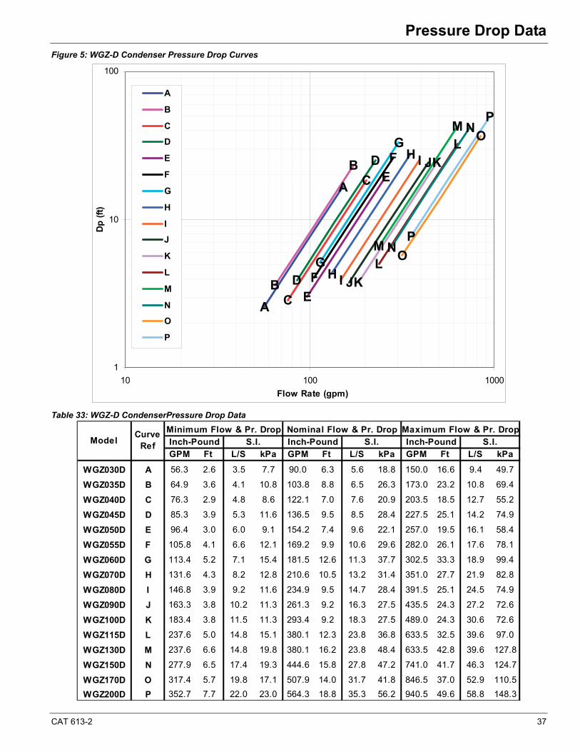
CAT 613-2 37
Pressure Drop DataPressure Drop Data
Figure 5: WGZ-D Condenser Pressure Drop Curves
Table 33: WGZ-D CondenserPressure Drop Data
A
B
B
C
C
D
D
E
E
F
F
G
G
H
H
I
I
J
J
K
K
L
L
M
M
N
N
O
O
P
P
A
1
10
100
10 100 1000
Flow Rate (gpm)
Dp
(ft
)A
B
C
D
E
F
G
H
I
J
K
L
M
N
O
P
GPM Ft L/S kPa GPM Ft L/S kPa GPM Ft L/S kPa
WGZ030D A 56.3 2.6 3.5 7.7 90.0 6.3 5.6 18.8 150.0 16.6 9.4 49.7
WGZ035D B 64.9 3.6 4.1 10.8 103.8 8.8 6.5 26.3 173.0 23.2 10.8 69.4
WGZ040D C 76.3 2.9 4.8 8.6 122.1 7.0 7.6 20.9 203.5 18.5 12.7 55.2
WGZ045D D 85.3 3.9 5.3 11.6 136.5 9.5 8.5 28.4 227.5 25.1 14.2 74.9
WGZ050D E 96.4 3.0 6.0 9.1 154.2 7.4 9.6 22.1 257.0 19.5 16.1 58.4
WGZ055D F 105.8 4.1 6.6 12.1 169.2 9.9 10.6 29.6 282.0 26.1 17.6 78.1
WGZ060D G 113.4 5.2 7.1 15.4 181.5 12.6 11.3 37.7 302.5 33.3 18.9 99.4
WGZ070D H 131.6 4.3 8.2 12.8 210.6 10.5 13.2 31.4 351.0 27.7 21.9 82.8
WGZ080D I 146.8 3.9 9.2 11.6 234.9 9.5 14.7 28.4 391.5 25.1 24.5 74.9
WGZ090D J 163.3 3.8 10.2 11.3 261.3 9.2 16.3 27.5 435.5 24.3 27.2 72.6
WGZ100D K 183.4 3.8 11.5 11.3 293.4 9.2 18.3 27.5 489.0 24.3 30.6 72.6
WGZ115D L 237.6 5.0 14.8 15.1 380.1 12.3 23.8 36.8 633.5 32.5 39.6 97.0
WGZ130D M 237.6 6.6 14.8 19.8 380.1 16.2 23.8 48.4 633.5 42.8 39.6 127.8
WGZ150D N 277.9 6.5 17.4 19.3 444.6 15.8 27.8 47.2 741.0 41.7 46.3 124.7
WGZ170D O 317.4 5.7 19.8 17.1 507.9 14.0 31.7 41.8 846.5 37.0 52.9 110.5
WGZ200D P 352.7 7.7 22.0 23.0 564.3 18.8 35.3 56.2 940.5 49.6 58.8 148.3
Curve Ref
Model Inch-Pound S.I.Minimum Flow & Pr. Drop Nominal Flow & Pr. Drop Maximum Flow & Pr. DropInch-Pound Inch-PoundS.I. S.I.
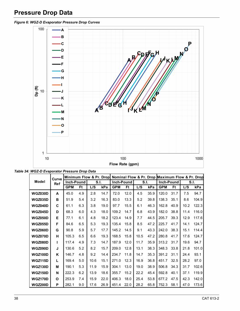
38 CAT 613-2
Pressure Drop Data
Figure 6: WGZ-D Evaporator Pressure Drop Curves
Table 34: WGZ-D Evaporator Pressure Drop Data
AB
B
C
C
D
D
E
E
F
F
G
G
H
H
I
I
J
J
K
K
L
L
M
M
N
N
O
O
P
P
A
1
10
100
10 100 1000
Flow Rate (gpm)
Dp
(ft
)
A
B
C
D
E
F
G
H
I
J
K
L
M
N
O
P
GPM Ft L/S kPa GPM Ft L/S kPa GPM Ft L/S kPa
WGZ030D A 45.0 4.9 2.8 14.7 72.0 12.0 4.5 35.9 120.0 31.7 7.5 94.7
WGZ035D B 51.9 5.4 3.2 16.3 83.0 13.3 5.2 39.8 138.3 35.1 8.6 104.9
WGZ040D C 61.1 6.3 3.8 19.0 97.7 15.5 6.1 46.3 162.8 40.9 10.2 122.3
WGZ045D D 68.3 6.0 4.3 18.0 109.2 14.7 6.8 43.9 182.0 38.8 11.4 116.0
WGZ050D E 77.1 6.1 4.8 18.2 123.4 14.9 7.7 44.5 205.7 39.3 12.9 117.6
WGZ055D F 84.6 6.5 5.3 19.3 135.4 15.8 8.5 47.2 225.7 41.7 14.1 124.7
WGZ060D G 90.8 5.9 5.7 17.7 145.2 14.5 9.1 43.3 242.0 38.3 15.1 114.4
WGZ070D H 105.3 6.5 6.6 19.3 168.5 15.8 10.5 47.2 280.8 41.7 17.6 124.7
WGZ080D I 117.4 4.9 7.3 14.7 187.9 12.0 11.7 35.9 313.2 31.7 19.6 94.7
WGZ090D J 130.6 5.2 8.2 15.7 209.0 12.8 13.1 38.3 348.3 33.8 21.8 101.0
WGZ100D K 146.7 4.8 9.2 14.4 234.7 11.8 14.7 35.3 391.2 31.1 24.4 93.1
WGZ115D L 169.4 5.0 10.6 15.1 271.0 12.3 16.9 36.8 451.7 32.5 28.2 97.0
WGZ130D M 190.1 5.3 11.9 15.9 304.1 13.0 19.0 38.9 506.8 34.3 31.7 102.6
WGZ150D N 222.3 6.2 13.9 18.6 355.7 15.2 22.2 45.4 592.8 40.1 37.1 119.9
WGZ170D O 253.9 7.4 15.9 22.0 406.3 18.0 25.4 53.8 677.2 47.5 42.3 142.0
WGZ200D P 282.1 9.0 17.6 26.9 451.4 22.0 28.2 65.8 752.3 58.1 47.0 173.6
Maximum Flow & Pr. DropCurve Ref S.I. Inch-Pound S.I.Inch-Pound Inch-PoundS.I.
Nominal Flow & Pr. DropModel
Minimum Flow & Pr. Drop

CAT 613-2 39
Physical Data - Packaged UnitsPhysical Data - Packaged Units
Table 35: Physical Data - WGZ030D - WGZ055D
Note 1: Capacity certified in accordance with AHRI Standard 550/590.Note 2: 90% Full R-410A at 90°F (32°C)
WGZ UNIT SIZEUnit capacity @ AHRI tons, (kW) (Note 1)
No. Circuits
COMPRESSORSNominal Tons 7.5 7.5 9 9 10 10 12 12 13 13 13 15Number Per Circuit 2 2 2 2 2 2 2 2 2 2 2 2
CAPACITY REDUCTION STEPS - PERCENT OF COMPRESSOR DISPLACEMENTStaging, Circuit #1 in Lead
Staging, Circuit #2 in Lead
Oil Charge per Compressor- oz. (l)
CONDENSERNumber
No. Refrigerant Circuits
Diameter- in. (mm)
Tube Length- in. (mm)
Design Working Pressure PSIG, (kPa): Refrigerant Side Water SidePump-Out Capacity- lb. (kg) (Note 2)
Victaulic Conn.In & Out- in. (mm)
Relief Valve, Flare- In. (mm)
Purge Valve, Flare- In. (mm)
Vent & Drain- in. (mm) NPT
Liquid Subcooling
EVAPORATOR, BRAZED-PLATENumberNo. Refrigerant Circuits
Water Volume- gal (l)Design Working Pressure- PSIG, (kPa): Refrigerant Side Water Side Victaulic Conn. In & Out- in. (mm) Relief Valve, Flare- in. (mm)Vent & Drain
UNIT DIMENSIONSLength- in. (mm)Width- in. (mm)Height- in. (mm)
UNIT WEIGHTSOperating Weight- lb. (kg)Shipping Weight- lb. (kg)Cir #1 R410A Oper Charge- lb. (kg) Cir #2 R410A Oper Charge- lb. (kg) 43 (19.5) 43 (19.5) 43 (19.5)
2523 (1144)
2
50 (22.7)
32.8 (832)
Integral
5/8 (15.9)
653 (4500)653 (4500)
50 (22.7)47 (21.4)
136.0 (3455) 136.0 (3455)
63.4 (1609)
5/8 (15.9)
2539 (1152)
136.0 (3455)
63.4 (1609)32.8 (832)
2606 (1182)43 (19.5) 43 (19.5) 43 (19.5) 47 (21.4) 47 (21.4)
2484 (1127) 2564 (1163) 2615 (1186) 2631 (1193) 2719 (1233)2408 (1092) 2488 (1129) 2618 (1188)
32.8 (832) 32.8 (832) 32.8 (832) 32.8 (832)63.4 (1609)
2731 (1239)
63.4 (1609)
136.0 (3455)
63.4 (1609) 63.4 (1609)
136.0 (3455) 136.0 (3455)
Field Field Field Field5/8 (15.9) 5/8 (15.9)
653 (4500)
2.5 (65) 2.5 (65) 2.5 (65) 2.5 (65)653 (4500)
2.5 (65)653 (4500)
2.5 (65)653 (4500) 653 (4500) 653 (4500)
Field Field5/8 (15.9) 5/8 (15.9)
653 (4500)
2
1.6 (6.1) 1.8 (6.8) 2.0 (7.6)
1 1 1
653 (4500) 653 (4500)
Integral
2
2.3 (8.7)
2 21
Integral Integral
205.4 (93.4)
4 (102)
5/8 (15.9) 5/8 (15.9)5/8 (15.9) 5/8 (15.9)
4 (102)4 (102)4 (102)
245.8 (111.7)
1/4 (6.4)
1/2 (12.7)
1/4 (6.4) 1/4 (6.4) 1/4 (6.4) 1/4 (6.4)
1/2 (12.7) 1/2 (12.7) 1/2 (12.7) 1/2 (12.7)
1/4 (6.4)
228.2 (103.7) 228.2 (103.7)232 (1599) 232 (1599)
5/8 (15.9)
4 (102)
232 (1599)
4 (102)
10 (254)
120 (3048)120 (3048)
232 (1599) 232 (1599)
120 (3048) 120 (3048)
2
500 (3447) 500 (3447) 500 (3447) 500 (3447)
222
10 (254) 10 (254) 10 (254) 10 (254)
245.8 (111.7)
120 (3048)120 (3048)
85 (2.5)
1 1
2
1 1
110 (3.3) 110 (3.3)
1
25 / 50 / 75 / 100 25 / 50 / 75 / 100
110 (3.3)
27 / 50 / 77 / 10025 / 50 / 75 / 100
030 035
30.0 (105.5) 34.6 (121.7) 40.7 (143.1) 45.5 (160.0)
25 / 50 / 75 / 100 25 / 50 / 75 / 100
2 2 2 2
Integral
1
040 045 055
23 / 50 / 73 / 100
25 / 50 / 75 / 100
25 / 50 / 75 / 100 25 / 50 / 75 / 100
56.4 (198.3)
232 (1599)500 (3447) 500 (3447)
110 (3.3)
2
25 / 50 / 75 / 100
1
1
2.8 (10.6)
22
2.6 (9.8)
5/8 (15.9)
653 (4500)
050
2
25 / 50 / 75 / 100
110 (3.3)
205.4 (93.4)
1/2 (12.7)
10 (254)
47 (21.4)
51.4 (180.7)
Integral
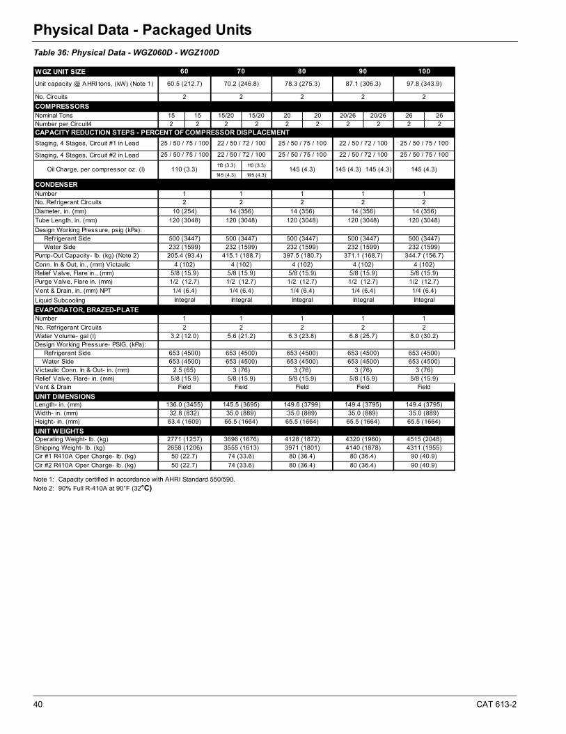
40 CAT 613-2
Physical Data - Packaged Units
Table 36: Physical Data - WGZ060D - WGZ100D
Note 1: Capacity certified in accordance with AHRI Standard 550/590.Note 2: 90% Full R-410A at 90°F (32°C)
WGZ UNIT SIZE
Unit capacity @ AHRI tons, (kW) (Note 1)
No. Circuits
COMPRESSORSNominal Tons 15 15 15/20 15/20 20 20 20/26 20/26 26 26Number per Circuit4 2 2 2 2 2 2 2 2 2 2CAPACITY REDUCTION STEPS - PERCENT OF COMPRESSOR DISPLACEMENT
Staging, 4 Stages, Circuit #1 in Lead
Staging, 4 Stages, Circuit #2 in Lead
110 (3.3) 110 (3.3)
145 (4.3) 145 (4.3)
CONDENSERNumberNo. Refrigerant Circuits
Diameter, in. (mm)
Tube Length, in. (mm)
Design Working Pressure, psig (kPa): Refrigerant Side Water SidePump-Out Capacity- lb. (kg) (Note 2)
Conn. In & Out, in., (mm) VictaulicRelief Valve, Flare in., (mm)Purge Valve, Flare in. (mm)
Vent & Drain, in. (mm) NPT
Liquid Subcooling
EVAPORATOR, BRAZED-PLATENumber
No. Refrigerant CircuitsWater Volume- gal (l)Design Working Pressure- PSIG, (kPa): Refrigerant Side Water Side Victaulic Conn. In & Out- in. (mm) Relief Valve, Flare- in. (mm)Vent & Drain
UNIT DIMENSIONSLength- in. (mm)Width- in. (mm)Height- in. (mm)
UNIT WEIGHTSOperating Weight- lb. (kg)Shipping Weight- lb. (kg)Cir #1 R410A Oper Charge- lb. (kg)
Cir #2 R410A Oper Charge- lb. (kg)
145 (4.3)
90 (40.9)
120 (3048) 120 (3048)
145 (4.3)
14 (356)
2
100
90 (40.9)
4515 (2048)
65.5 (1664)
149.4 (3795)
50 (22.7) 74 (33.6) 80 (36.4) 80 (36.4)
50 (22.7) 74 (33.6) 80 (36.4) 80 (36.4)
2658 (1206) 3555 (1613) 3971 (1801) 4140 (1878) 4311 (1955)2771 (1257) 3696 (1676) 4128 (1872) 4320 (1960)
63.4 (1609) 65.5 (1664) 65.5 (1664) 65.5 (1664)32.8 (832) 35.0 (889) 35.0 (889) 35.0 (889) 35.0 (889)
136.0 (3455) 145.5 (3695) 149.6 (3799) 149.4 (3795)
Field Field Field Field Field5/8 (15.9) 5/8 (15.9) 5/8 (15.9) 5/8 (15.9) 5/8 (15.9)2.5 (65) 3 (76) 3 (76) 3 (76) 3 (76)
653 (4500) 653 (4500) 653 (4500) 653 (4500) 653 (4500)653 (4500) 653 (4500) 653 (4500) 653 (4500) 653 (4500)
3.2 (12.0) 5.6 (21.2) 6.3 (23.8) 6.8 (25.7) 8.0 (30.2)2 2 2 2 2
1 1 1 1 1
Integral Integral Integral Integral Integral
1/4 (6.4) 1/4 (6.4) 1/4 (6.4) 1/4 (6.4) 1/4 (6.4)
1/2 (12.7) 1/2 (12.7) 1/2 (12.7) 1/2 (12.7) 1/2 (12.7)5/8 (15.9) 5/8 (15.9) 5/8 (15.9) 5/8 (15.9) 5/8 (15.9)
4 (102) 4 (102) 4 (102) 4 (102) 4 (102)
205.4 (93.4) 415.1 (188.7) 397.5 (180.7) 371.1 (168.7) 344.7 (156.7)232 (1599) 232 (1599) 232 (1599) 232 (1599) 232 (1599)
500 (3447)
14 (356)
78.3 (275.3) 87.1 (306.3) 97.8 (343.9)
2 2
Oil Charge, per compressor oz. (l) 110 (3.3) 145 (4.3) 145 (4.3)
60 70 80 90
60.5 (212.7) 70.2 (246.8)
2 2
120 (3048) 120 (3048) 120 (3048)
10 (254) 14 (356) 14 (356)
22 / 50 / 72 / 100 25 / 50 / 75 / 100 22 / 50 / 72 / 100
1
500 (3447) 500 (3447) 500 (3447) 500 (3447)
25 / 50 / 75 / 10025 / 50 / 75 / 100 22 / 50 / 72 / 100 25 / 50 / 75 / 100 22 / 50 / 72 / 100
25 / 50 / 75 / 100 25 / 50 / 75 / 100
12 2 2 2 21 1 1
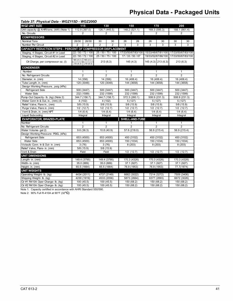
CAT 613-2 41
Physical Data - Packaged Units
Table 37: Physical Data - WGZ115D - WGZ200D
Note 1: Capacity certified in accordance with AHRI Standard 550/590.Note 2: 90% Full R-410A at 90°F (32°C)
WGZ UNIT SIZEUnit capacity @ AHRI tons, (kW) (Note 1) No. Circuits
COMPRESSORS Nominal Tons 26/30 26/30 30 30 26 26 26 30 30 30 Number Per Circuit 2 2 2 2 3 3 3 3 3 3
CAPACITY REDUCTION STEPS - PERCENT OF COMPRESSOR DISPLACEMENT Staging, 4 Stages, Circuit #1 in Lead Staging, 4 Stages, Circuit #2 in Lead
145 (4.3 ) 145 (4.3 )
213 (6.3) 213 (6.3)
CONDENSER Number
No. Refrigerant Circuits
Diameter, in. (mm) Tube Length, in. (mm) Design Working Pressure., psig (kPa): Refrigerant Side Water SidePump-Out Capacity- lb. (kg) (Note 2) Water Conn In & Out, in., (mm) (4) Relief Valve, Flare in., (mm) Purge Valve, Flare in. (mm) Vent & Drain, in. (mm) NPT Liquid Subcooling
EVAPORATOR, BRAZED-PLATENumber
No. Refrigerant CircuitsWater Volume- gal (l)Design Working Pressure- PSIG, (kPa): Refrigerant Side Water Side Victaulic Conn. In & Out- in. (mm) Relief Valve, Flare- in. (mm)Vent & Drain
UNIT DIMENSIONSLength- in. (mm)Width- in. (mm)Height- in. (mm)
UNIT WEIGHTSOperating Weight- lb. (kg)Shipping Weight- lb. (kg)Cir #1 R410A Oper Charge- lb. (kg) Cir #2 R410A Oper Charge- lb. (kg)
22
200112.9 (397.0) 126.7 (445.5) 148.2 (521.1) 169.3 (595.3)
115 130
213 (6.3)
188.1 (661.4)
17/33/50/67/83/10022 / 50 / 72 / 100 25 / 50 / 75 / 100
25 / 50 / 75 / 100 15/33/48/67/81/10017/33/50/67/83/100
150 170
Oil Charge, per compressor oz. (l) 145 (4.3) 145 (4.3) 213 (6.3)213 (6.3)
2 2 2
22 / 50 / 72 / 100
1 1 1
120 (3048) 144 (3658) 144 (3658)
1
2 2 2 2 2
1
16 (406.4)
500 (3447) 500 (3447) 500 (3447) 500 (3447) 500 (3447)
16 (406.4)120 (3048)
232 (1599) 232 (1599) 232 (1599)
144 (3658)14 (356) 14 (356) 16 (406.4)
4 (102) 4 (102) 5 (127)
232 (1599)344.7 (156.7) 344.7 (156.7) 572.3 (260.1) 508.9 (231.3) 508.9 (231.3)232 (1599)
2 2 2 2 2
5/8 (15.9) 5/8 (15.9) 5/8 (15.9) 5/8 (15.9) 5/8 (15.9)
450 (3102) 450 (3102) 450 (3102)
9.6 (36.3) 10.8 (40.9) 57.6 (218.0) 56.9 (215.4) 56.9 (215.4)
653 (4500) 653 (4500)
3 (76) 3 (76) 8 (203) 8 (203) 8 (203)653 (4500) 653 (4500) 150 (1034) 150 (1034) 150 (1034)
Field Field 1/2 (12.7) 1/2 (12.7) 1/2 (12.7)
150 (68.2)100 (45.5) 100 (45.5) 150 (68.2)
170.3 (4326)149.4 (3795) 149.4 (3795) 170.3 (4326)
150 (68.2)
6672 (3026)100 (45.5) 100 (45.5) 150 (68.2) 150 (68.2) 150 (68.2)
4230 (1919) 4533 (2056) 5873 (2664) 6377 (2893)4434 (2011) 4737 (2149) 6662 (3022) 7214 (3272) 7509 (3406)
1
19/33/52/67/86/100 17/33/50/67/83/10017 / 33 / 50 / 67
Integral Integral Integral
5 (127)
1/2 (12.7)
5 (127)
Integral
1/2 (12.7)
1 1 11
Integral
SHELL-AND-TUBE
1/2 (12.7)1/4 (6.4) 1/4 (6.4) 1/4 (6.4) 1/4 (6.4) 1/4 (6.4)
1/2 (12.7) 1/2 (12.7)
35.0 (889)65.5 (1664)
5/8 (15.9) 5/8 (15.9)
37.1 (927)77.7(1974)
35.0 (889)65.5 (1664) 76.9 (1953) 76.9 (1953)
37.1 (927)170.3 (4326)
37.1 (927)
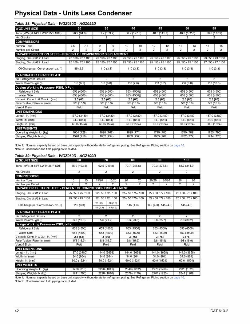
42 CAT 613-2
Physical Data - Units Less CondenserPhysical Data - Units Less Condenser
Table 38: Physical Data - WGZ030D - AGZ055D
Note 1: Nominal capacity based on base unit capacity without derate for refrigerant piping. See Refrigerant Piping section on page 10.Note 2: Condenser and field piping not included.
Table 39: Physical Data - WGZ060D - AGZ100D
Note 1: Nominal capacity based on base unit capacity without derate for refrigerant piping. See Refrigerant Piping section on page 10.Note 2: Condenser and field piping not included.
WGZ UNIT SIZE
Tons (kW) (at 44°F LWT/125°F SDT)
No. Circuits
COMPRESSORSNominal Tons 7.5 7.5 9 9 10 10 12 12 13 13 13 15Number per Circuit 2 2 2 2 2 2 2 2 2 2 2 2
CAPACITY REDUCTION STEPS - PERCENT OF COMPRESSOR DISPLACEMENTStaging, Circuit #1 in Lead
Staging, Circuit #2 in Lead
EVAPORATOR, BRAZED PLATENo. Refrigerant Circuits
Water Volume- gal (l)
Design Working Pressure- PSIG, (kPa): Refrigerant Side Water Side Victaulic Conn. In & Out- in. (mm) Relief Valve, Flare- in. (mm)
Vent & Drain
UNIT DIMENSIONSLength- in. (mm)
Width- in. (mm)
Height- in. (mm)
UNIT WEIGHTSOperating Weight- lb. (kg)Shipping Weight- lb. (kg)
Field
1714 (778)1578 (716) 1662 (754) 1669 (757) 1685 (764)1740 (789)
2
25 / 50 / 75 / 100
2.5 (65) 2.5 (65)5/8 (15.9)
653 (4500)
5/8 (15.9)
653 (4500)
5/8 (15.9) 5/8 (15.9)
653 (4500)
5/8 (15.9)2.5 (65)
653 (4500)2.5 (65) 2.5 (65)
25 / 50 / 75 / 100 25 / 50 / 75 / 100 25 / 50 / 75 / 100 25 / 50 / 75 / 100
2.8 (10.6)2.0 (7.6) 2.3 (8.7) 2.6 (9.8)
110 (3.3)
2
34.0 (864) 34.0 (864)
1604 (728) 1690 (767) 1699 (771) 1719 (780)
60.0 (1524) 60.0 (1524)
1702 (772)
34.0 (864)
1755 (796)
34.0 (864)
60.0 (1524) 60.0 (1524)
34.0 (864)
2.5 (65)5/8 (15.9)
Field Field
34.0 (864)
60.0 (1524) 60.0 (1524)
137.0 (3480) 137.0 (3480) 137.0 (3480) 137.0 (3480) 137.0 (3480) 137.0 (3480)
653 (4500)
Field Field Field
653 (4500) 653 (4500)) 653 (4500)
35
653 (4500) 653 (4500)) 653 (4500)
110 (3.3) 110 (3.3)
1.8 (6.8)
2
110 (3.3)
27 / 50 / 77 / 100
50.6 (177.9)
50 55
31.2 (109.7)
2
45
36.2 (127.3) 40.3 (141.7)
25 / 50 / 75 / 100
2
22
25 / 50 / 75 / 100
23 / 50 / 73 / 100
2
25 / 50 / 75 / 100
110 (3.3)
2
40
2
26.9 (94.6)
25 / 50 / 75 / 100
46.3 (162.8)
2
25 / 50 / 75 / 100
2
30
653 (4500)
Oil Charge per Compressor- oz. (l) 85 (2.5)
1.6 (6.1)
WGZ UNIT SIZE
Tons (kW) (at 44°F LWT/125°F SDT)
No. Circuits
COMPRESSORSNominal Tons 15 15 15/20 15/20 20 20 20/26 20/26 26 26Number per Circuit 2 2 2 2 2 2 2 2 2 2CAPACITY REDUCTION STEPS - PERCENT OF COMPRESSOR DISPLACEMENT
Staging, Circuit #1 in Lead
Staging, Circuit #2 in Lead
110 (3.3) 110 (3.3)
145 (4.3) 145 (4.3)
EVAPORATOR, BRAZED PLATENo. Refrigerant CircuitsWater Volume- gal (l)
Design Working Pressure- PSIG, (kPa): Refrigerant Side
Water Side Victaulic Conn. In & Out- in. (mm) Relief Valve, Flare- in. (mm)Vent & Drain
UNIT DIMENSIONSLength- in. (mm)Width- in. (mm)
Height- in. (mm)
UNIT WEIGHTSOperating Weight- lb. (kg)
Shipping Weight- lb. (kg)
Oil Charge per Compressor- oz. (l) 110 (3.3) 145 (4.3) 145 (4.3) 145 (4.3) 145 (4.3)
25 / 50 / 75 / 100 22 / 50 / 72 / 100 25 / 50 / 75 / 100 22 / 50 / 72 / 100
90
2 2 2 2
55.0 (193.4) 62.5 (219.8) 79.3 (278.8)
144.0 (3658) 144.0 (3658)
2841 (1289)
2923 (1326)
2701 (1225)
1786 (810) 2296 (1041)
1741 (790) 2228 (1010) 2579 (1170)
25 / 50 / 75 / 100 22 / 50 / 72 / 100 25 / 50 / 75 / 100 22 / 50 / 72 / 100
653 (4500)
3.2 (12.0)2 2 2
8.0 (30.2)
88.7 (311.9)
25 / 50 / 75 / 100
2
2
653 (4500)
2
34.0 (864)
Field
144.0 (3658)
Field
653 (4500)
34.0 (864)
Field Field
144.0 (3658)34.0 (864) 34.0 (864)
137.0 (3480)
60 70 80
70.7 (248.6)
60.0 (1524) 60.0 (1524) 60.0 (1524) 60.0 (1524)60.0 (1524)
2649 (1202)
5/8 (15.9) 5/8 (15.9) 5/8 (15.9) 5/8 (15.9)2.5 (63) 3 (76) 3 (76) 3 (76)
5/8 (15.9)
2778 (1260)
34.0 (864)
Field
3 (76)
653 (4500)
25 / 50 / 75 / 100
6.3 (23.8) 6.8 (25.7)
653 (4500) 653 (4500) 653 (4500) 653 (4500)
653 (4500)
5.6 (21.2)
653 (4500)
100
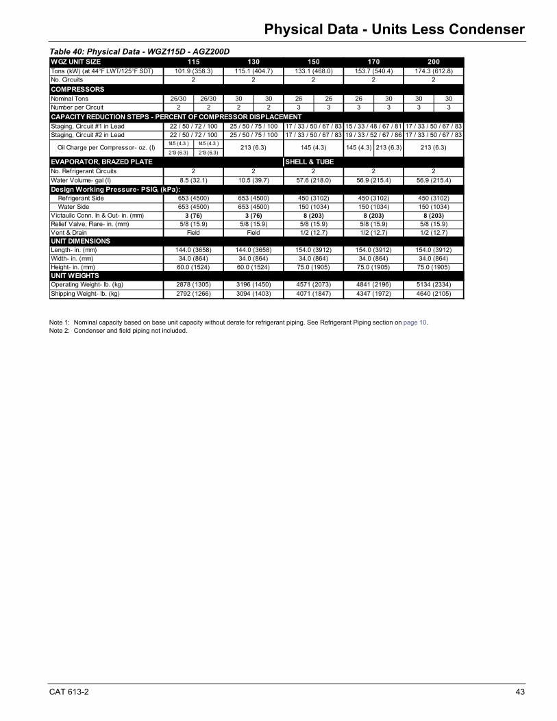
CAT 613-2 43
Physical Data - Units Less Condenser
Table 40: Physical Data - WGZ115D - AGZ200D
Note 1: Nominal capacity based on base unit capacity without derate for refrigerant piping. See Refrigerant Piping section on page 10.Note 2: Condenser and field piping not included.
WGZ UNIT SIZETons (kW) (at 44°F LWT/125°F SDT)No. Circuits
COMPRESSORSNominal Tons 26/30 26/30 30 30 26 26 26 30 30 30Number per Circuit 2 2 2 2 3 3 3 3 3 3
CAPACITY REDUCTION STEPS - PERCENT OF COMPRESSOR DISPLACEMENTStaging, Circuit #1 in LeadStaging, Circuit #2 in Lead
145 (4.3 ) 145 (4.3 )
213 (6.3) 213 (6.3)
EVAPORATOR, BRAZED PLATE SHELL & TUBENo. Refrigerant Circuits
Water Volume- gal (l)
Design Working Pressure- PSIG, (kPa): Refrigerant Side Water Side Victaulic Conn. In & Out- in. (mm) Relief Valve, Flare- in. (mm)Vent & DrainUNIT DIMENSIONSLength- in. (mm)Width- in. (mm)Height- in. (mm)UNIT WEIGHTSOperating Weight- lb. (kg)
Shipping Weight- lb. (kg)
56.9 (215.4)
75.0 (1905)60.0 (1524) 60.0 (1524) 75.0 (1905) 75.0 (1905)
154.0 (3912)34.0 (864)
144.0 (3658)
1/2 (12.7)Field Field 1/2 (12.7) 1/2 (12.7)
144.0 (3658) 154.0 (3912) 154.0 (3912)34.0 (864) 34.0 (864) 34.0 (864) 34.0 (864)
8 (203)5/8 (15.9) 5/8 (15.9) 5/8 (15.9) 5/8 (15.9) 5/8 (15.9)
4640 (2105)
5134 (2334)2878 (1305) 3196 (1450) 4571 (2073) 4841 (2196)
2792 (1266) 3094 (1403) 4071 (1847) 4347 (1972)
450 (3102)653 (4500) 653 (4500) 150 (1034) 150 (1034) 150 (1034)
10.5 (39.7) 57.6 (218.0) 56.9 (215.4)
2
3 (76) 3 (76) 8 (203) 8 (203)
653 (4500) 653 (4500) 450 (3102) 450 (3102)
2
8.5 (32.1)
2
170
2 2 2
213 (6.3)
25 / 50 / 75 / 100 17 / 33 / 50 / 67 / 83
200
Oil Charge per Compressor- oz. (l) 213 (6.3) 145 (4.3) 145 (4.3) 213 (6.3)
22 / 50 / 72 / 100
174.3 (612.8)2
153.7 (540.4)
17 / 33 / 50 / 67 / 83 15 / 33 / 48 / 67 / 81 19 / 33 / 52 / 67 / 86
17 / 33 / 50 / 67 / 83
133.1 (468.0)
22 / 50 / 72 / 100 25 / 50 / 75 / 100 17 / 33 / 50 / 67 / 83
2 2 2
115 130 150101.9 (358.3) 115.1 (404.7)
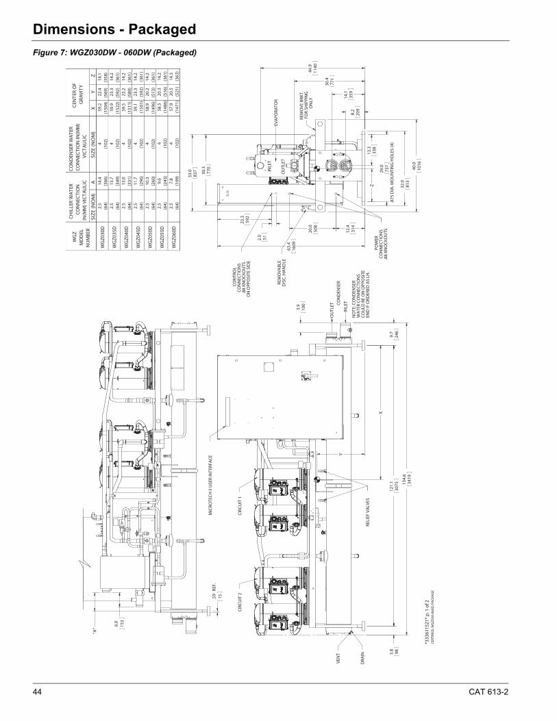
44 CAT 613-2
Dimensions - PackagedDimensions - Packaged
Figure 7: WGZ030DW - 060DW (Packaged)
121.
130
753.
898
134.
634
19
9.7
246
X
Y
29.0
.875
DIA
. MO
UN
TIN
G H
OLE
S (4
)73
7
13.3
338
2.0
51
23.3
592
Z
"A"
15.59
REF
.
*333
6115
21*
p. 1
of 2
CERT
IFIE
D, W
GZ0
30-0
60D
, PA
CKA
GE
CIR
CU
IT 2
OU
TLET
INLE
T
DRA
IN
VEN
T
WA
TER
CO
NN
ECTI
ON
S
MIC
ROTE
CH
II U
SER
INTE
RFA
CE
CO
ND
ENSE
R
CO
ULD
BE
ON
OPP
OSI
TE
NO
TE: C
ON
DEN
SER
END
IF O
RDER
ED A
S LH
.
CIR
CU
IT 1
RELI
EF V
ALV
ES
3.9
100
EVA
PORA
TOR
FOR
SHIP
PIN
G
OU
TLET
REM
OVE
BRK
T.
DIS
C. H
AN
DLE
.88
KNO
CKO
UTS
.88
KNO
CKO
UTS
CO
NN
ECTI
ON
S
INLE
T
ON
OPP
OSI
TE S
IDE
REM
OVA
BLE
ON
LY
POW
ER
CO
NTR
OL
CO
NN
ECTI
ON
S
770
30.3
1609
63.4
30.4
771
14.1
359
8.2
209
32.0
813
1140
44.9
1016
40.0
314
12.4
508
20.0
33.0
837
6.0
153
CO
ND
ENSE
R W
ATER
C
ON
NEC
TIO
N IN
(MM
) VI
CTA
ULI
C
SIZ
E (N
OM
)A
SIZ
E (N
OM
)X
YZ
2.5
14.4
459
.222
.414
.1(6
4)(3
66)
(102
)(1
504)
(569
)(3
58)
2.5
13.7
459
.923
.314
.2(6
4)(3
49)
(102
)(1
522)
(592
)(3
61)
2.5
13.0
459
.523
.214
.2(6
4)(3
31)
(102
)(1
511)
(589
)(3
61)
2.5
11.7
459
.123
.314
.2(6
4)(2
96)
(102
)(1
501)
(592
)(3
61)
2.5
10.3
458
.920
.214
.2(6
4)(2
60)
(102
)(1
496)
(513
)(3
61)
2.5
9.6
458
.520
.314
.2(6
4)(2
43)
(102
)(1
486)
(516
)(3
61)
2.5
7.8
457
.920
.514
.3(6
4)(1
99)
(102
)(1
471)
(521
)(3
63)
CH
ILLE
R W
ATER
C
ON
NEC
TIO
N
IN(M
M) V
ICTA
ULI
C
CEN
TER
OF
GRA
VITY
WG
Z M
OD
EL
NU
MBE
R
WG
Z030
D
WG
Z055
D
WG
Z060
D
WG
Z035
D
WG
Z040
D
WG
Z045
D
WG
Z050
D
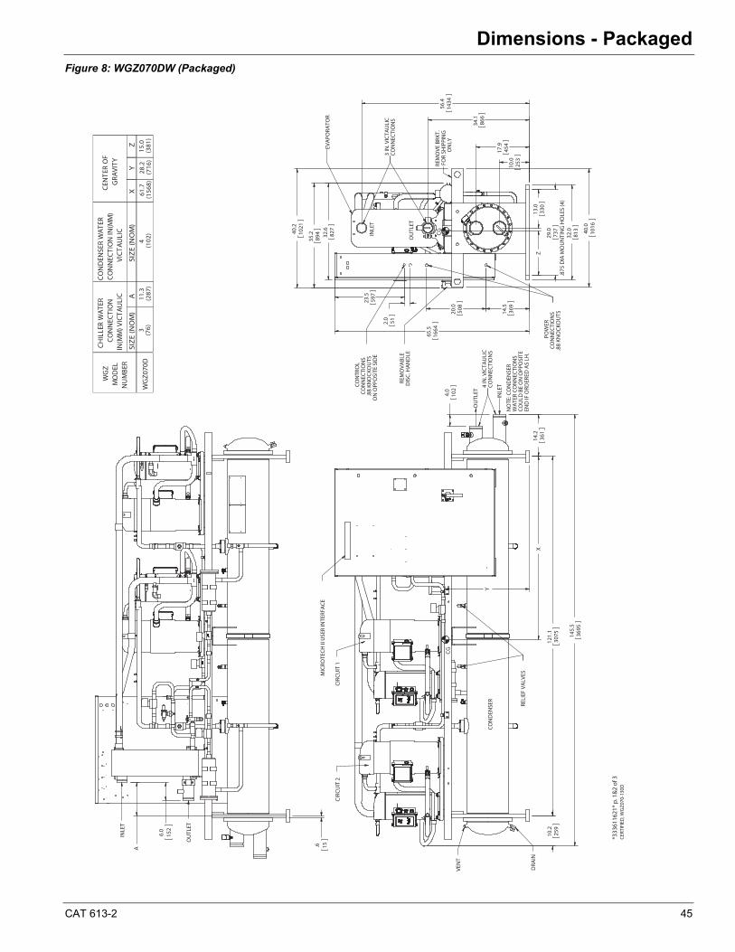
CAT 613-2 45
Dimensions - Packaged
Figure 8: WGZ070DW (Packaged)
145.
536
95
10.2
259
121.
130
75
14.2
361
X
Y
2.0 51
29.0
.875
DIA
MO
UN
TIN
G H
OLE
S (4
)73
7
13.0
330
23.5
597
Z
*333
6116
21*
p. 1
&2
of 3
CER
TIFI
ED, W
GZ0
70-1
30D
VEN
T
DRA
IN
CG
NO
TE: C
ON
DEN
SER
WA
TER
CO
NN
ECTI
ON
S
CO
ND
ENSE
R
OU
TLET
CO
ULD
BE
ON
OPP
OSI
TE
MIC
ROTE
CH
II U
SER
INTE
RFA
CE
INLE
T
END
IF O
RDER
ED A
S LH
.RE
LIEF
VA
LVES
CIR
CU
IT 2
CIR
CU
IT 1
4 IN
. VIC
TAU
LIC
CO
NN
ECTI
ON
S
4.0
102
ON
LY
REM
OVE
BRK
T.
INLE
T
FOR
SHIP
PIN
G
.88
KNO
CKO
UTS
CO
NN
ECTI
ON
S
REM
OVA
BLE
.88
KNO
CKO
UTS
CO
NTR
OL
DIS
C. H
AN
DLE
CO
NN
ECTI
ON
S
EVA
PORA
TOR
CG
ON
OPP
OSI
TE S
IDE
OU
TLET
POW
ER
3 IN
. VIC
TAU
LIC
CO
NN
ECTI
ON
S
14.5
369
20.0
508
65.5
1664
35.2
894 32
.682
7
1016
40.0
1434
56.4
866
34.1
454
17.9
253
10.0
813
32.040
.210
21
.6 15A
OU
TLET
INLE
T
6.0
152
CO
ND
ENSE
R W
ATER
C
ON
NEC
TIO
N IN
(MM
) VI
CTA
ULI
C
SIZ
E (N
OM
)A
SIZ
E (N
OM
)X
YZ
3
CH
ILLE
R W
ATER
C
ON
NEC
TIO
N
IN(M
M) V
ICTA
ULI
C
CEN
TER
OF
GRA
VITY
WG
Z M
OD
EL
NU
MBE
R
WG
Z070
D(7
6)11
.3(2
87)
4(1
02)
61.7
(156
8)28
.2(7
16)
15.0
(381
)
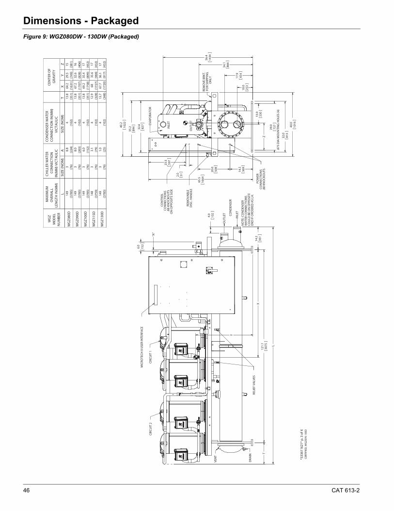
46 CAT 613-2
Dimensions - Packaged
Figure 9: WGZ080DW - 130DW (Packaged)
121.
130
75
14.2
361
L
T
Y
X
"A"
2.0
51
29.0
.875
DIA
MO
UN
TIN
G H
OLE
S (4
)73
7
13.0
330
23.5
597
Z
*333
6116
21*
p. 3
of 4
CER
TIFI
ED, W
GZ0
70-1
30D
MIC
ROTE
CH
II U
SER
INTE
RFA
CE
CIR
CU
IT 2
CIR
CU
IT 1
CO
ND
ENSE
R
RELI
EF V
ALV
ES
VEN
T
OU
TLET
INLE
T
DRA
IN
NO
TE: C
ON
DEN
SER
WA
TER
CO
NN
ECTI
ON
SC
OU
LD B
E O
N O
PPO
SITE
END
IF O
RDER
ED A
S LH
.
4.0
102
6.0
152
POW
ERC
ON
NEC
TIO
NS
.88
KNO
CKO
UTS
REM
OVA
BLE
DIS
C. H
AN
DLE
CO
NTR
OL
CO
NN
ECTI
ON
S.8
8 KN
OC
KOU
TSO
N O
PPO
SITE
SID
E
REM
OVE
BRK
T.FO
R SH
IPPI
NG
ON
LY
EVA
PORA
TOR
INLE
T
OU
TLET
40.0
1016
56.4
1434
34.1
866
17.9
454
10.0
253
32.0
813
20.0
508
14.5
369
65.5
1664
35.2
89440
.210
22
32.6
827
MAX
IMU
M
OVE
RALL
LE
NG
TH IN
(MM
)
CO
ND
ENSE
R W
ATE
R C
ON
NEC
TIO
N IN
(MM
) VI
CTA
ULI
C
LSI
ZE
(NO
M)
ASI
ZE
(NO
M)
TX
YZ
149
38.
84
13.8
64.2
29.5
15(3
785)
(76)
(224
)(1
02)
(351
)(1
631)
(749
)(3
81)
149
38.
04
13.8
67.2
32.6
16(3
785)
(76)
(203
)(1
02)
(351
)(1
707)
(828
)(4
06)
149
36.
04
13.8
69.2
35.4
17(3
785)
(76)
(152
)(1
02)
(351
)(1
758)
(899
)(4
32)
148
33.
14
12.9
6835
.617
(375
9)(7
6)(7
9)(1
02)
(328
)(1
727)
(904
)(4
32)
149
31.
04
13.7
67.7
36.1
17(3
785)
(76)
(25)
(102
)(3
48)
(172
0)(9
17)
(432
)
CH
ILLE
R W
ATER
C
ON
NEC
TIO
N
IN(M
M) V
ICTA
ULI
C
CEN
TER
OF
GRA
VITY
WG
Z130
D
WG
Z080
D
WG
Z M
OD
EL
NU
MBE
R
WG
Z090
D
WG
Z100
D
WG
Z115
D
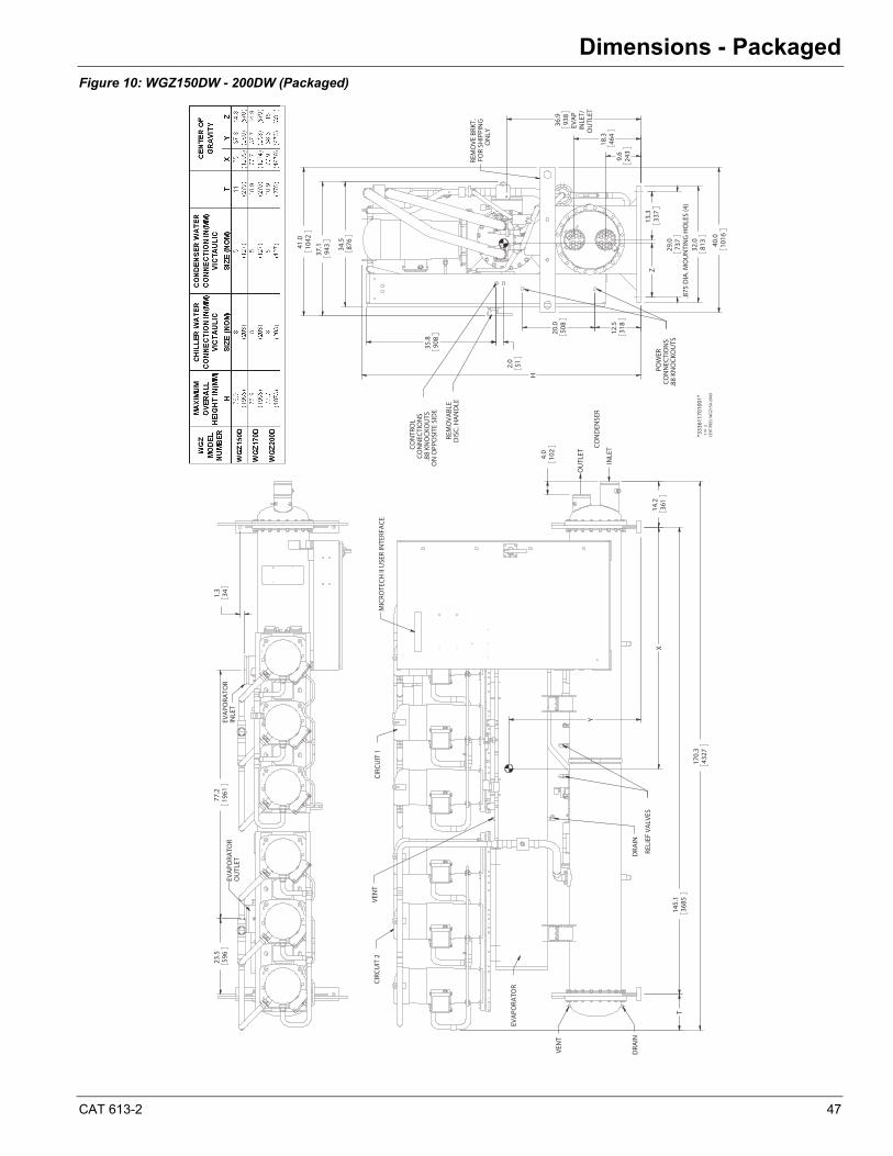
CAT 613-2 47
Dimensions - Packaged
Figure 10: WGZ150DW - 200DW (Packaged)
4.0
102
170.
343
27
145.
136
85
14.2
361
T
Y
X
MIC
ROTE
CH II
USE
R IN
TERF
ACE
CIRC
UIT
2CI
RCU
IT 1
CON
DEN
SER
RELI
EF V
ALV
ES
VEN
T
DRA
IN
OU
TLET
INLE
T
EVA
PORA
TOR
DRA
IN
VEN
T
9.6
243
18.3
464
32.0
813 40
.010
16
20.0
508
12.5
318
H
41.0
1042
37.1
943 34
.587
6
29.0
.875
DIA
. MO
UN
TIN
G H
OLE
S (4
)73
7
2.0 51
36.9
EVA
PIN
LET/
OU
TLET
938
13.3
337
35.8
908
ZPO
WER
CON
NEC
TIO
NS
.88
KNO
CKO
UTS
REM
OVA
BLE
DIS
C. H
AN
DLE
CON
TRO
LCO
NN
ECTI
ON
S.8
8 KN
OCK
OU
TSO
N O
PPO
SITE
SID
E
REM
OVE
BRK
T.FO
R SH
IPPI
NG
ON
LY
1.3 34
23.5
596
77.2
1961
EVA
PORA
TOR
OU
TLET
EVA
PORA
TOR
INLE
T
CERT
IFIE
D, W
GZ1
50-2
00D
1
2
OF
*333
6117
0100
1*
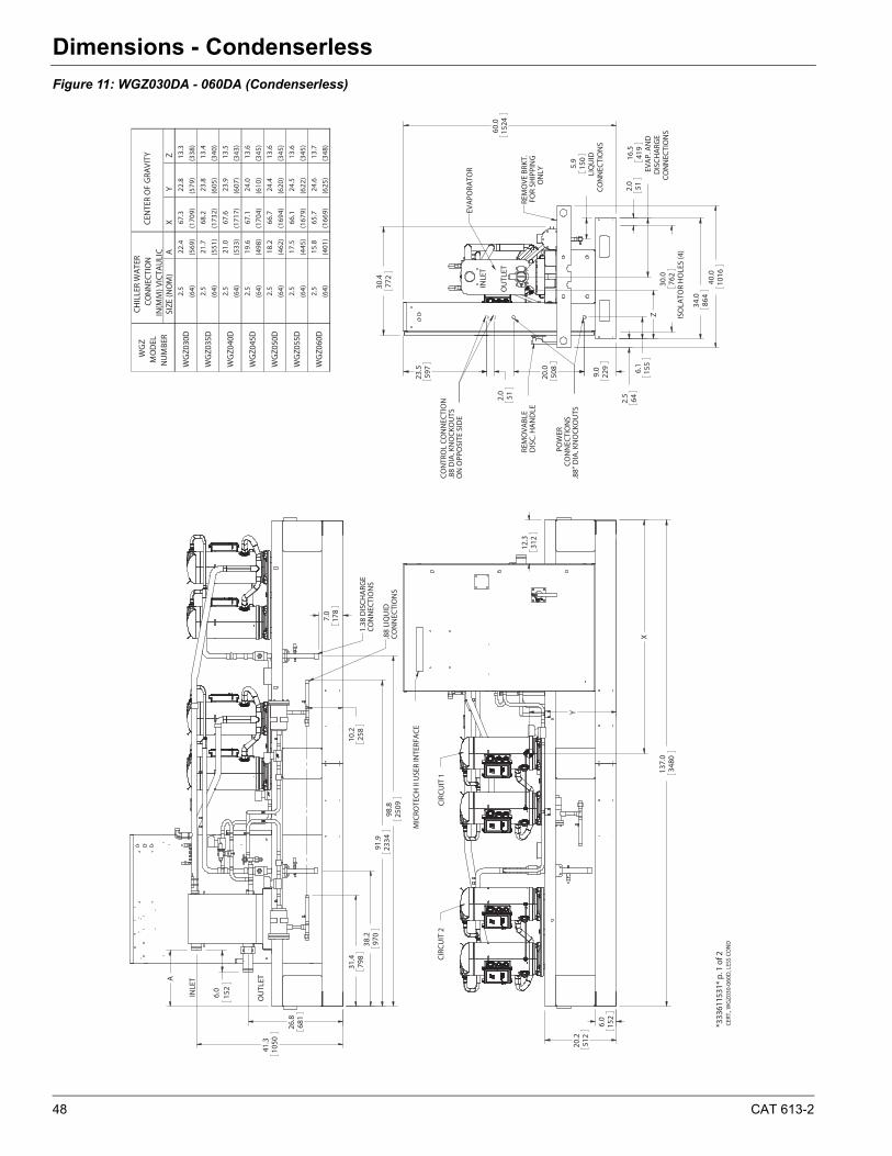
48 CAT 613-2
Dimensions - CondenserlessDimensions - Condenserless
Figure 11: WGZ030DA - 060DA (Condenserless)
Y
X
2.0
51
23.5
597
Z
41.3
1050
26.8
681
*333
6115
31*
p. 1
of 2
CERT
., W
GZ0
30-0
60D
, LES
S CO
ND
CIR
CU
IT 1
CIR
CU
IT 2
MIC
ROTE
CH
II U
SER
INTE
RFA
CE
137.
034
80
152
312
12.3
6.0
20.2
512
ON
LY
OU
TLET
FOR
SHIP
PIN
GD
ISC
. HA
ND
LERE
MO
VABL
ERE
MO
VE B
RKT.
.88
DIA
. KN
OC
KOU
TS
INLE
T
ON
OPP
OSI
TE S
IDE
EVA
PORA
TOR
CO
NTR
OL
CO
NN
ECTI
ON
POW
ERC
ON
NEC
TIO
NS
.88"
DIA
. KN
OC
KOU
TS
ISO
LATO
R H
OLE
S (4
)76
2
DIS
CH
ARG
E
60.0
419
CO
NN
ECTI
ON
S
5.9
150
CO
NN
ECTI
ON
SLI
QU
ID
1524
2.5
642.
06.
115
5
34.0
864
40.0
1016
9.0
229
20.0
508
5116
.5
EVA
P. A
ND
30.0
30.4
772
.88
LIQ
UID
INLE
T
OU
TLET
CO
NN
ECTI
ON
S
1.38
DIS
CH
ARG
EC
ON
NEC
TIO
NS
98.8
178
7.0
2509
2334
91.9
38.2
970
31.4
798
258
A
10.2
6.0
152
SIZE
(NO
M)
AX
YZ
2.5
22.4
67.3
22.8
13.3
(64)
(569
)(1
709)
(579
)(3
38)
2.5
21.7
68.2
23.8
13.4
(64)
(551
)(1
732)
(605
)(3
40)
2.5
21.0
67.6
23.9
13.5
(64)
(533
)(1
717)
(607
)(3
43)
2.5
19.6
67.1
24.0
13.6
(64)
(498
)(1
704)
(610
)(3
45)
2.5
18.2
66.7
24.4
13.6
(64)
(462
)(1
694)
(620
)(3
45)
2.5
17.5
66.1
24.5
13.6
(64)
(445
)(1
679)
(622
)(3
45)
2.5
15.8
65.7
24.6
13.7
(64)
(401
)(1
669)
(625
)(3
48)
CHIL
LER
WA
TER
CON
NEC
TIO
N
IN(M
M) V
ICTA
ULI
CCE
NTE
R O
F G
RAVI
TYW
GZ
MO
DEL
N
UM
BER
WG
Z030
D
WG
Z055
D
WG
Z060
D
WG
Z035
D
WG
Z040
D
WG
Z045
D
WG
Z050
D
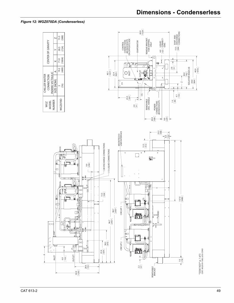
CAT 613-2 49
Dimensions - Condenserless
Figure 12: WGZ070DA (Condenserless)
Y
572.2
X
2.0
51
23.5
597
Z
CERT
. WG
Z070
-130
D, L
ESS
CON
D*3
3361
1631
* p.
1 o
f 3
CIR
CU
IT 2
REM
OVA
BLE
USE
R IN
TERF
AC
E
CG
BRA
CKE
T
CIR
CU
IT 1
MIC
ROTE
CH
II
312
12.3
588
152
137.
0
23.2
3480
6.0
7.0
178
CO
NTR
OL
CG
ON
LY
.88
KNO
CKO
UTS
CO
NN
ECT-
ION
S
FOR
SHIP
PIN
G
OU
TLET
EVA
PORA
TOR
EVA
P. A
ND
ON
OPP
OSI
TE S
IDE
REM
OVA
BLE
DIS
CH
ARG
E
DIS
C. H
AN
DLE
.88
KNO
CKO
UTS
CO
NN
ECTI
ON
S
CO
NN
ECTI
ON
S
INLE
T
LIQ
UID
POW
ERC
ON
NEC
TIO
NS
REM
OVE
BRA
CKE
T.
229
9.0
512.0
762
ISO
LATO
R H
OLE
S (4
)
15.5
394
34.0
864
1.5
38
40.0
1016
4.0
101
155
32.4
823
60.0
1524
20.0
508
6.1
30.040
.110
17
1.38
DIS
CH
ARG
E C
ON
NEC
TIO
NS
INLE
T
1.13
LIQ
UID
CO
NN
ECTI
ON
S
OU
TLET
2457
96.7
659
25.9
28.6
725
338
13.3
98.7
2507
50.9
1293
38.2
970
A
9.4
238
6.0
152
SIZE
(NO
M)
AX
YZ
3 (76)
CHIL
LER
WA
TER
CON
NEC
TIO
N
IN(M
M) V
ICTA
ULI
CCE
NTE
R O
F G
RAVI
TYW
GZ
MO
DEL
N
UM
BER
WG
Z070
D19
.2(4
89)
71.0
(180
4)28
.5(7
24)
15.3
(388
)
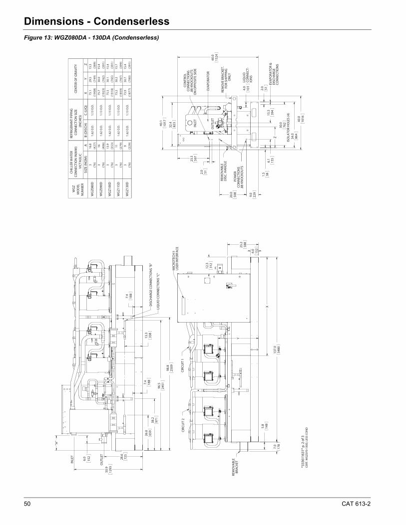
50 CAT 613-2
Dimensions - Condenserless
Figure 13: WGZ080DA - 130DA (Condenserless)
X
Y
2.0
51
23.5
597
Z
CERT
. WG
Z070
-130
D, L
ESS
CON
D*3
3361
1631
* p.
2 o
f 3
REM
OVA
BLE
USE
R IN
TERF
AC
E
CIR
CU
IT 2
MIC
ROTE
CH
II
CIR
CU
IT 1
BRA
CKE
T
152
148
6.0
137.
034
80
12.3
312
5.8
588
23.2
7.0
178
CO
NN
ECTI
ON
S
INLE
T
FOR
SHIP
PIN
G
CO
NN
ECTI
ON
SD
ISC
HA
RGE
CO
NTR
OL
DIS
C. H
AN
DLE
ION
S
ON
OPP
OSI
TE S
IDE
.88
KNO
CKO
UTS
REM
OVE
BRA
CKE
T.RE
MO
VABL
E
EVA
PORA
TOR
OU
TLET
.88
KNO
CKO
UTS
ON
LY
LIQ
UID
CO
NN
ECT-
POW
ERC
ON
NEC
TIO
NS
EVA
PORA
TOR
&6.
115
5
229
9.0
20.0
508
60.0
1524
2.0
51
ISO
LATO
R H
OLE
S (4
)76
2
394
15.5
864
34.0
32.4
1.5
38
40.0
1016
4.0
101
823
30.040
.110
17
DIS
CH
ARG
E C
ON
NEC
TIO
NS
"B"
OU
TLET
LIQ
UID
CO
NN
ECTI
ON
S "C
"
INLE
T
50.9
1293
28.6
725
7.4
"A"
188
96.5
2451
26.0
659
971
38.2
188
7.4
2509
98.8
338
13.3
6.0
152
SIZE
(NO
M)
AB
(DIS
CH
)C
(LIQ
)X
YZ
316
.875
.129
.515
.3
)9
83(
)94
7()
80
91()
72
4()
67(
316
75.7
30.0
15.4
)1
93(
)26
7()
32
91()
60
4()
67(
313
.975
.530
.115
.4
)1
93(
)56
7()
81
91()
35
3()
67(
311
73.2
30.2
15.7
)9
93(
)76
7()
95
81()
97
2()
67(
39
73.9
30.7
15.4
)1
93(
)08
7()
77
81()
92
2()
67(
1.62
O.D
.
1.13
O.D
.
1.13
O.D
.
1.13
O.D
.
1.13
O.D
.
WG
Z130
D
WG
Z080
D
WG
Z090
D
WG
Z100
D
WG
Z115
D
1.13
O.D
.
1.62
O.D
.
1.62
O.D
.
1.62
O.D
.
1.62
O.D
.
WG
Z M
OD
EL
NU
MBE
R
CHIL
LER
WA
TER
CON
NEC
TIO
N IN
(MM
) VI
CTA
ULI
CCE
NTE
R O
F G
RAVI
TYRE
FRIG
ERA
NT
PIPI
NG
CO
NN
ECTI
ON
SIZ
E (IN
CHES
)

CAT 613-2 51
Dimensions - Condenserless
Figure 14: WGZ150DA - 200DA (Condenserless) (see next page for more dimensions)
154.
039
12
1.9 48
Y
X
CIRC
UIT
1CI
RCU
IT 2
MIC
ROTE
CH II
USE
R IN
TERF
ACE
74.9
1903
40.0
1016
34.0
864
4.0
LIQ
UID
CON
NEC
TIO
NS
101
30.0
ISO
LATO
R H
OLE
S (6
)76
22.
0 51
20.0
508
9.0
229
5.0
127
2.9 74
40.5
1029
2.0 51
23.5
597
Z
REM
OVA
BLE
DIS
C. H
AN
DLE
POW
ERCO
NN
ECTI
ON
S.8
8 KN
OCK
OU
TS(Q
TY. 3
)
CON
TRO
LCO
NN
ECTI
ON
S.8
8 KN
OCK
OU
TSO
N O
PPO
SITE
SID
E
REM
OVE
BRK
T.FO
R SH
IPPI
NG
ON
LY
CERT
. WG
Z150
-200
D, L
ESS
CON
D.
*333
6117
1100
1*
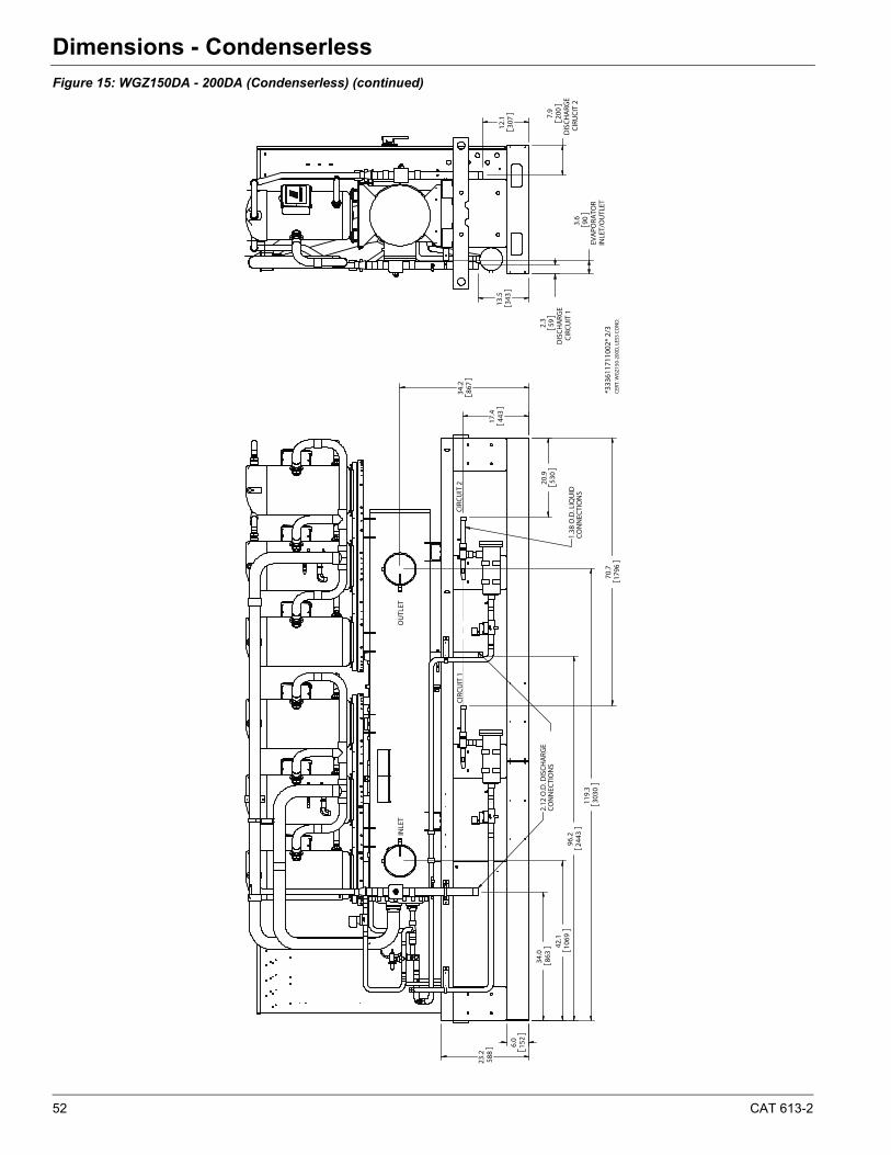
52 CAT 613-2
Dimensions - Condenserless
Figure 15: WGZ150DA - 200DA (Condenserless) (continued)
23.2
588
6.0
152
42.1
1069
119.
330
30
70.7
1796
20.9
530
34.2
867
17.4
443
34.0
863
96.2
2443IN
LET
OU
TLET
2.12
O.D
. DIS
CHA
RGE
CON
NEC
TIO
NS
1.38
O.D
. LIQ
UID
CON
NEC
TIO
NS
CIRC
UIT
1CI
RCU
IT 2
3.6
EVA
PORA
TOR
INLE
T/O
UTL
ET
90
2.3
DIS
CHA
RGE
CIRC
UIT
1
597.
9
DIS
CHA
RGE
CIRU
CIT
2
200
12.1
307
13.5
343
CERT
. WG
Z150
-200
D, L
ESS
CON
D.
*333
6117
1100
2* 2
/3
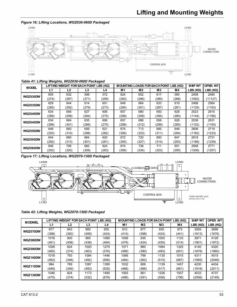
CAT 613-2 53
Lifting and Mounting WeightsLifting and Mounting Weights
Figure 16: Lifting Locations, WGZ030-060D Packaged
Table 41: Lifting Weights, WGZ030-060D Packaged
Figure 17: Lifting Locations, WGZ070-130D Packaged
Table 42: Lifting Weights, WGZ070-130D Packaged
L1/M1 L2/M2
L3/M3L4/M4
CONTROL BOX
WATERCONNECTIONS
L1 L2 L3 L4 M1 M2 M3 M4
605 632 598 572 624 652 617 590 2408 2484(274) (287) (271) (259) (283) (296) (280) (268) (1092) (11127)629 644 614 601 649 664 633 619 2488 2564
(285) (292) (279) (273) (294) (301) (287) (281) (1129) (1163)634 656 627 606 657 680 650 628 2523 2615
(288) (298) (284) (275) (298) (308) (295) (285) (1144) (1186)634 664 635 606 657 688 658 628 2539 2631
(288) (301) (288) (275) (298) (312) (299) (285) (1152) (1193)646 683 656 621 674 713 685 648 2606 2719
(293) (310) (298) (282) (306) (323) (311) (294) (1182) (1233)644 690 664 620 672 720 693 647 2618 2731
(292) (313) (301) (281) (305) (327) (314) (293) (1188) (1239)646 706 682 624 674 736 711 651 2658 2771
(293) (320) (309) (283) (306) (334) (323) (295) (1206) (1257)
MODELLIFTING WEIGHT FOR EACH POINT LBS (KG) MOUNTING LOADS FOR EACH POINT LBS (KG)
WGZ030DW
WGZ035DW
WGZ040DW
WGZ045DW
WGZ050DW
SHIP WTLBS (KG)
WGZ055DW
WGZ060DW
OPER. WTLBS (KG)
CONTROL BOX
WATERCONNECTIONS
L3/M3
L2/M2L1/M1
L4/M4
CERTIFIED, WGZ070-130D*333611601003* p3/3
L1 L2 L3 L4 M1 M2 M3 M4
877 843 900 935 912 877 935 973 3555 3696(398) (382) (408) (424) (414) (398) (424) (441) (1613) (1676)1016 900 965 1090 1056 935 1003 1133 3971 4128(461) (408) (438) (494) (479) (424) (455) (514) (1801) (1872)1026 824 1020 1270 1071 860 1064 1325 4140 4320(465) (374) (463) (576) (486) (390) (483) (601) (1878) (1960)1018 763 1084 1446 1066 799 1135 1515 4311 4515(462) (346) (492) (656) (484) (362) (515) (687) (1955) (2048)984 769 1087 1390 1032 806 1139 1457 4230 4434
(446) (349) (493) (630) (468) (366) (517) (661) (1919) (2011)1046 824 1173 1490 1093 861 1226 1557 4533 4737(475) (374) (532) (676) (496) (391) (556) (706) (2056) (2149)
WGZ130DW
MOUNTING LOADS FOR EACH POINT LBS (KG)
WGZ070DW
WGZ080DW
WGZ090DW
MODWELLIFTING WEIGHT FOR EACH POINT LBS (KG) SHIP WT
LBS (KG)OPER. WTLBS (KG)
WGZ100DW
WGZ115DW
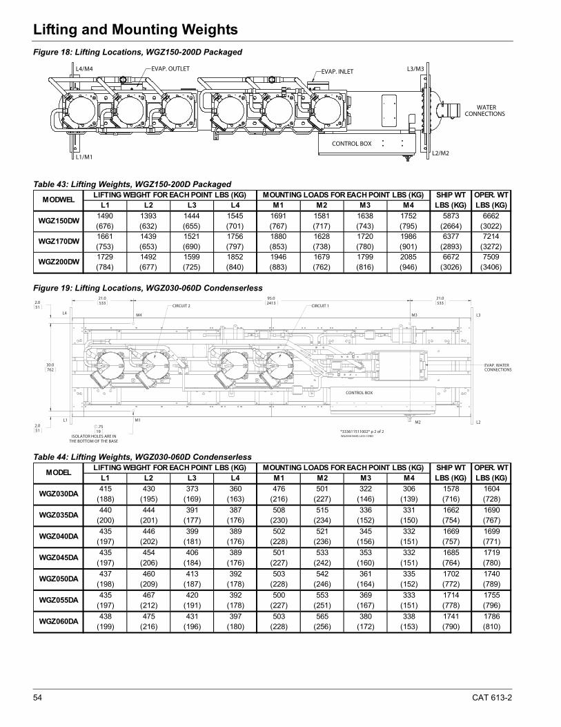
54 CAT 613-2
Lifting and Mounting Weights
Figure 18: Lifting Locations, WGZ150-200D Packaged
Table 43: Lifting Weights, WGZ150-200D Packaged
Figure 19: Lifting Locations, WGZ030-060D Condenserless
Table 44: Lifting Weights, WGZ030-060D Condenserless
EVAP. OUTLET EVAP. INLET
CONTROL BOX
WATERCONNECTIONS
L4/M4
L1/M1
L3/M3
L2/M2
L1 L2 L3 L4 M1 M2 M3 M4
1490 1393 1444 1545 1691 1581 1638 1752 5873 6662(676) (632) (655) (701) (767) (717) (743) (795) (2664) (3022)1661 1439 1521 1756 1880 1628 1720 1986 6377 7214(753) (653) (690) (797) (853) (738) (780) (901) (2893) (3272)1729 1492 1599 1852 1946 1679 1799 2085 6672 7509(784) (677) (725) (840) (883) (762) (816) (946) (3026) (3406)
WGZ150DW
WGZ170DW
WGZ200DW
MODWELLIFTING WEIGHT FOR EACH POINT LBS (KG) MOUNTING LOADS FOR EACH POINT LBS (KG) SHIP WT
LBS (KG)OPER. WTLBS (KG)
21.0533
95.02413
21.05332.0
51
30.0762
2.051
.75
ISOLATOR HOLES ARE INTHE BOTTOM OF THE BASE
19
CONTROL BOX
EVAP. WATERCONNECTIONS
CIRCUIT 1CIRCUIT 2
L4
L1
M4
M1 M2 L2
L3M3
WGZ030-060D, LESS COND*333611511002* p 2 of 2
L1 L2 L3 L4 M1 M2 M3 M4
415 430 373 360 476 501 322 306 1578 1604(188) (195) (169) (163) (216) (227) (146) (139) (716) (728)
440 444 391 387 508 515 336 331 1662 1690(200) (201) (177) (176) (230) (234) (152) (150) (754) (767)
435 446 399 389 502 521 345 332 1669 1699(197) (202) (181) (176) (228) (236) (156) (151) (757) (771)
435 454 406 389 501 533 353 332 1685 1719(197) (206) (184) (176) (227) (242) (160) (151) (764) (780)
437 460 413 392 503 542 361 335 1702 1740(198) (209) (187) (178) (228) (246) (164) (152) (772) (789)
435 467 420 392 500 553 369 333 1714 1755(197) (212) (191) (178) (227) (251) (167) (151) (778) (796)
438 475 431 397 503 565 380 338 1741 1786(199) (216) (196) (180) (228) (256) (172) (153) (790) (810)
SHIP WTLBS (KG)
OPER. WTLBS (KG)
LIFTING WEIGHT FOR EACH POINT LBS (KG) MOUNTING LOADS FOR EACH POINT LBS (KG)
WGZ055DA
WGZ060DA
MODEL
WGZ030DA
WGZ035DA
WGZ040DA
WGZ045DA
WGZ050DA
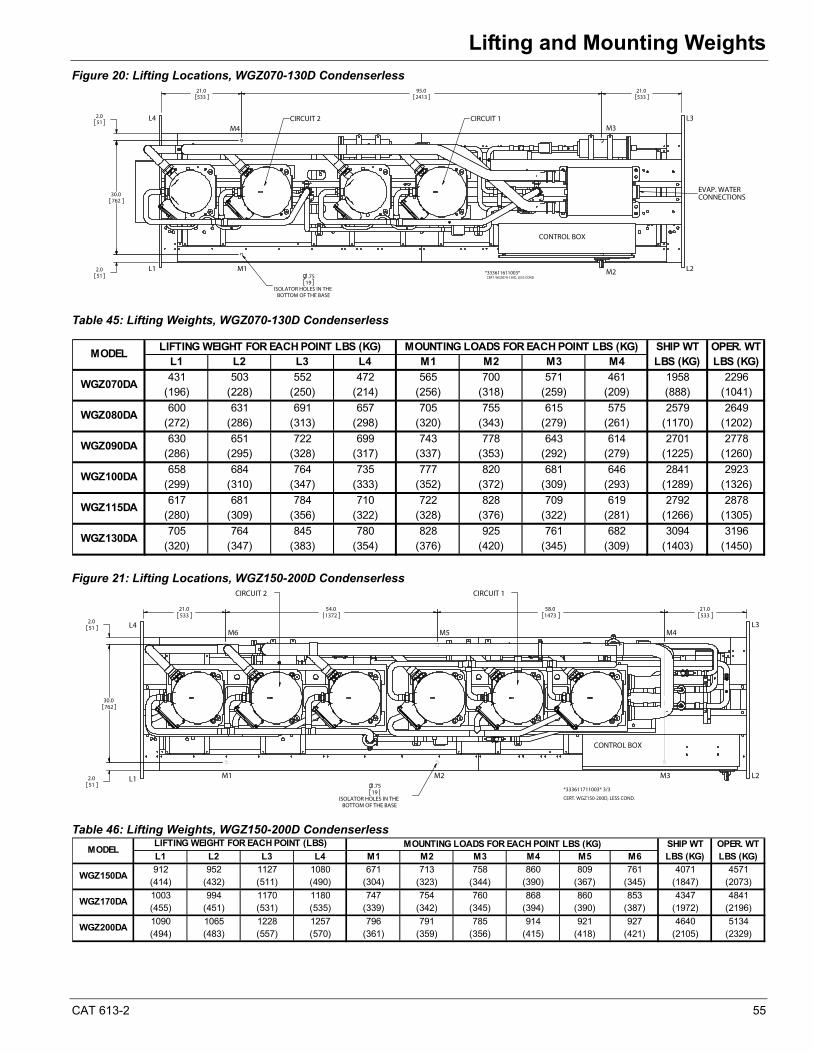
CAT 613-2 55
Lifting and Mounting Weights
Figure 20: Lifting Locations, WGZ070-130D Condenserless
Table 45: Lifting Weights, WGZ070-130D Condenserless
Figure 21: Lifting Locations, WGZ150-200D Condenserless
Table 46: Lifting Weights, WGZ150-200D Condenserless
.75
ISOLATOR HOLES IN THEBOTTOM OF THE BASE
19
21.0533
95.02413
21.0533
30.0762
2.051
2.051
CIRCUIT 1CIRCUIT 2
EVAP. WATERCONNECTIONS
CONTROL BOX
L4
L1 L2
L3
M1 M2
M3M4
CERT. WGZ070-130D, LESS COND*333611611003*
L1 L2 L3 L4 M1 M2 M3 M4
431 503 552 472 565 700 571 461 1958 2296(196) (228) (250) (214) (256) (318) (259) (209) (888) (1041)
600 631 691 657 705 755 615 575 2579 2649(272) (286) (313) (298) (320) (343) (279) (261) (1170) (1202)
630 651 722 699 743 778 643 614 2701 2778(286) (295) (328) (317) (337) (353) (292) (279) (1225) (1260)
658 684 764 735 777 820 681 646 2841 2923(299) (310) (347) (333) (352) (372) (309) (293) (1289) (1326)
617 681 784 710 722 828 709 619 2792 2878(280) (309) (356) (322) (328) (376) (322) (281) (1266) (1305)
705 764 845 780 828 925 761 682 3094 3196(320) (347) (383) (354) (376) (420) (345) (309) (1403) (1450)
SHIP WTLBS (KG)
OPER. WTLBS (KG)
MOUNTING LOADS FOR EACH POINT LBS (KG)LIFTING WEIGHT FOR EACH POINT LBS (KG)
WGZ115DA
WGZ130DA
WGZ070DA
WGZ080DA
WGZ090DA
WGZ100DA
MODEL
21.0533
54.01372
58.01473
21.0533
2.051
2.051
30.0762
.75
ISOLATOR HOLES IN THEBOTTOM OF THE BASE
19
M1L1 L2M2 M3
L3M4
L4M5M6
CONTROL BOX
CIRCUIT 1CIRCUIT 2
CERT. WGZ150-200D, LESS COND.
*333611711003* 3/3
L1 L2 L3 L4 M1 M2 M3 M4 M5 M6
912 952 1127 1080 671 713 758 860 809 761 4071 4571(414) (432) (511) (490) (304) (323) (344) (390) (367) (345) (1847) (2073)
1003 994 1170 1180 747 754 760 868 860 853 4347 4841(455) (451) (531) (535) (339) (342) (345) (394) (390) (387) (1972) (2196)
1090 1065 1228 1257 796 791 785 914 921 927 4640 5134(494) (483) (557) (570) (361) (359) (356) (415) (418) (421) (2105) (2329)
SHIP WTLBS (KG)
LIFTING WEIGHT FOR EACH POINT (LBS) OPER. WTLBS (KG)
MOUNTING LOADS FOR EACH POINT LBS (KG)
WGZ170DA
WGZ200DA
MODEL
WGZ150DA
56 CAT 613-2
Electrical DataElectrical Data
Electrical Notes
Notes for "Electrical Data Single Point" Power:
1 If a separate 115V power supply is used for the control circuit, then the wire sizing amps is 10 amps for all unit sizes.
2 Recommended power lead wire sizes for 3 conductors per conduit are based on 100% conductor ampacity in accordance with NEC. Voltage drop has not been included. It is recommended that power leads be kept short. All terminal block connections must be made with copper (type THW) wire.
3 The recommended power lead wire sizes are based on an ambient temperature of 86°F (30°C). Ampacity correction factors must be applied for other ambient temperatures. Refer to the National Electrical Code Handbook.
4 Must be electrically grounded according to national and local electrical codes.
Voltage Limitations:
1 Within 10 percent of nameplate rating
2 Voltage unbalance not to exceed 2% with a resultant current unbalance of 6 to 10 times the voltage unbalance per NEMA MG-1, 1998 Standard. This is an important restriction that must be adhered to.
Notes for "Field Wiring Data"
1 Requires a single disconnect to supply electrical power to the unit. This power supply must either be fused or use an HACR type circuit breaker.
2 All field wiring to unit power block or optional non-fused disconnect switch must be copper.
3 All field wire size values given in table apply to 75°C rated wire per NEC.
Supplemental Overloads Option
The supplemental overloads option is used to reduce the required electrical service size and wire sizing (cost) to the water cooled version of WGZ chillers. The overloads reduce the electrical requirements for the chiller because water-cooled duty requires less power than air-cooled duty. The overload option is only available for WGZ-DW models with water-cooled condensers, having single point electrical power connections, and can only be used if the condenser leaving water temperature is 105°F or less. Refer to the Compressor Amp Draw tables in the following electrical data for the reduced electrical requirements.
Circuit Breakers
The circuit breaker used in the High Short Circuit panel option may have a higher trip rating than the unit Maximum Overload Protection (MOP) value shown on the unit name plate. The circuit breaker is installed as a service disconnect switch and does not function as branch circuit protection, mainly that the protection device must be installed at the point of origin of the power wiring. The breaker (disconnect switch) is oversized to avoid nuisance trips at high ambient temperature conditions.
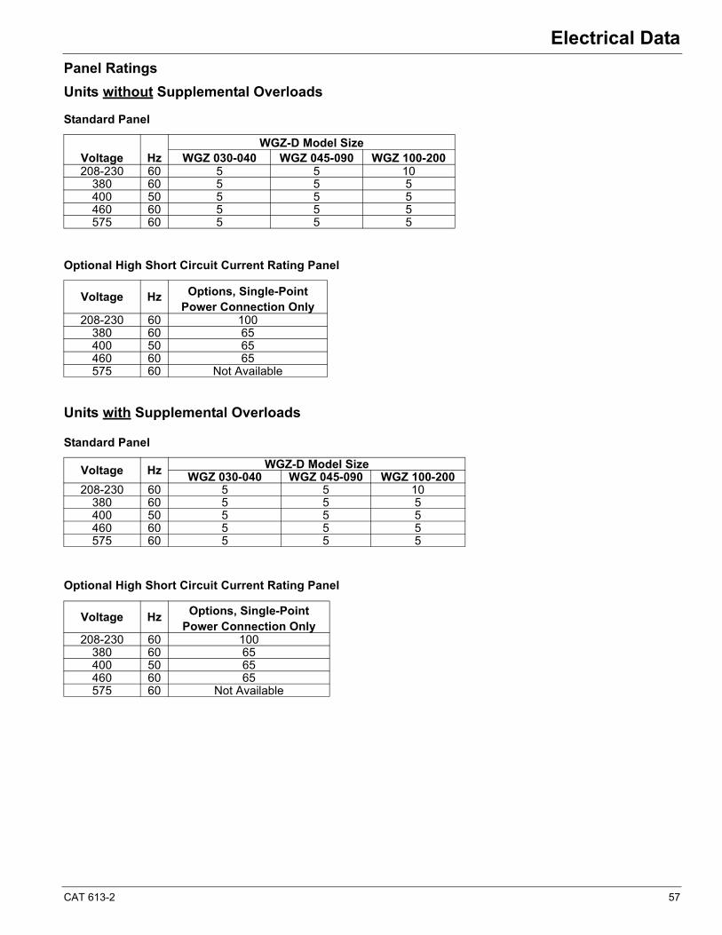
CAT 613-2 57
Electrical Data
Panel Ratings
Units without Supplemental Overloads
Standard Panel
Optional High Short Circuit Current Rating Panel
Units with Supplemental Overloads
Standard Panel
Optional High Short Circuit Current Rating Panel
Voltage HzWGZ-D Model Size
WGZ 030-040 WGZ 045-090 WGZ 100-200208-230 60 5 5 10
380 60 5 5 5400 50 5 5 5460 60 5 5 5575 60 5 5 5
Voltage Hz Options, Single-Point Power Connection Only
208-230 60 100380 60 65400 50 65460 60 65575 60 Not Available
Voltage Hz WGZ-D Model Size WGZ 030-040 WGZ 045-090 WGZ 100-200
208-230 60 5 5 10380 60 5 5 5400 50 5 5 5460 60 5 5 5575 60 5 5 5
Voltage Hz Options, Single-Point Power Connection Only
208-230 60 100380 60 65400 50 65460 60 65575 60 Not Available
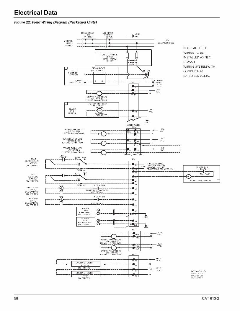
58 CAT 613-2
Electrical Data
Figure 22: Field Wiring Diagram (Packaged Units)
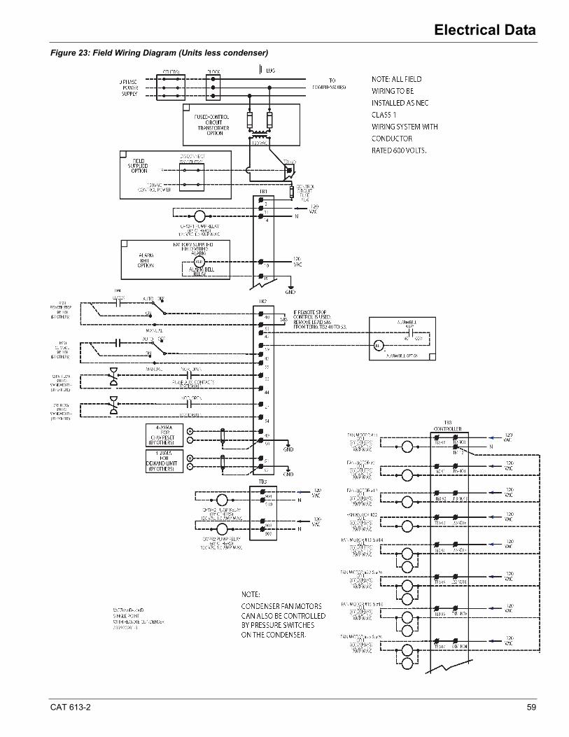
CAT 613-2 59
Electrical Data
Figure 23: Field Wiring Diagram (Units less condenser)
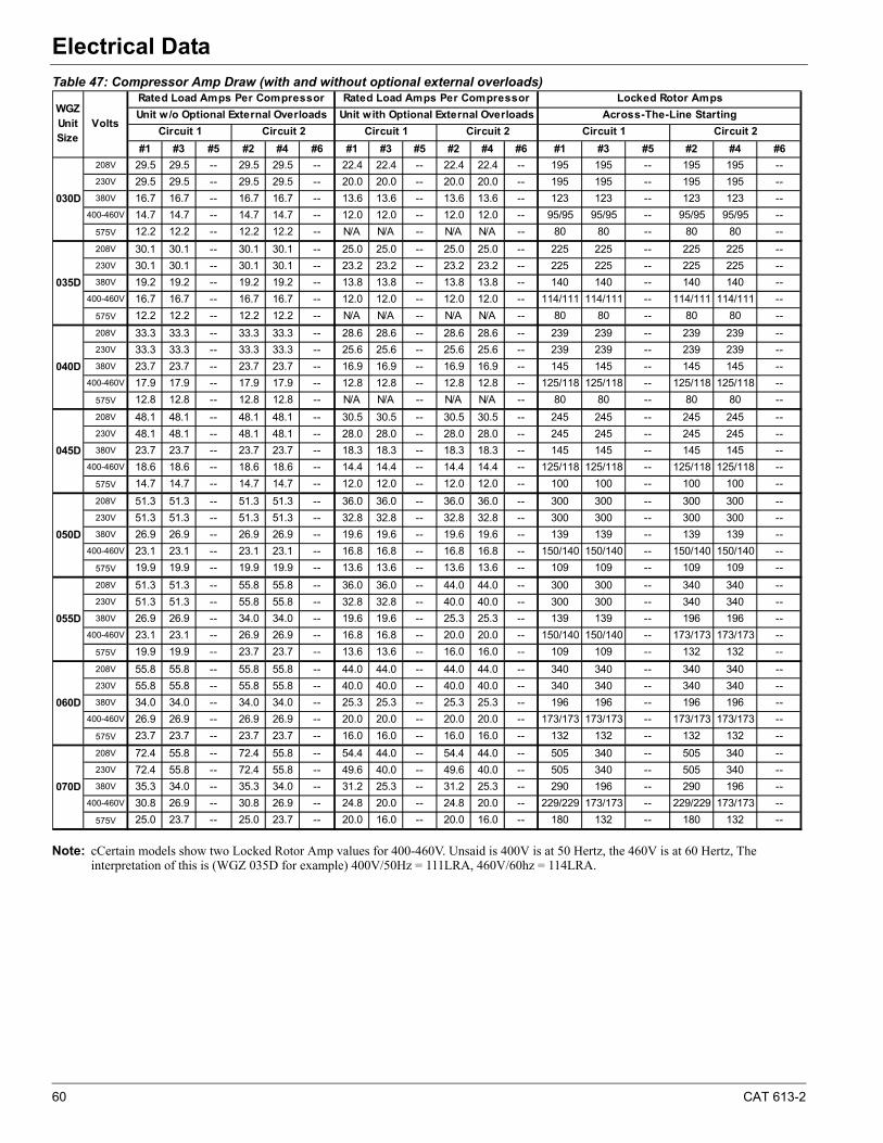
60 CAT 613-2
Electrical Data
Table 47: Compressor Amp Draw (with and without optional external overloads)
Note: cCertain models show two Locked Rotor Amp values for 400-460V. Unsaid is 400V is at 50 Hertz, the 460V is at 60 Hertz, The interpretation of this is (WGZ 035D for example) 400V/50Hz = 111LRA, 460V/60hz = 114LRA.
#1 #3 #5 #2 #4 #6 #1 #3 #5 #2 #4 #6 #1 #3 #5 #2 #4 #6
208V 29.5 29.5 -- 29.5 29.5 -- 22.4 22.4 -- 22.4 22.4 -- 195 195 -- 195 195 --
230V 29.5 29.5 -- 29.5 29.5 -- 20.0 20.0 -- 20.0 20.0 -- 195 195 -- 195 195 --
380V 16.7 16.7 -- 16.7 16.7 -- 13.6 13.6 -- 13.6 13.6 -- 123 123 -- 123 123 --
400-460V 14.7 14.7 -- 14.7 14.7 -- 12.0 12.0 -- 12.0 12.0 -- 95/95 95/95 -- 95/95 95/95 --
575V 12.2 12.2 -- 12.2 12.2 -- N/A N/A -- N/A N/A -- 80 80 -- 80 80 --
208V 30.1 30.1 -- 30.1 30.1 -- 25.0 25.0 -- 25.0 25.0 -- 225 225 -- 225 225 --
230V 30.1 30.1 -- 30.1 30.1 -- 23.2 23.2 -- 23.2 23.2 -- 225 225 -- 225 225 --
380V 19.2 19.2 -- 19.2 19.2 -- 13.8 13.8 -- 13.8 13.8 -- 140 140 -- 140 140 --
400-460V 16.7 16.7 -- 16.7 16.7 -- 12.0 12.0 -- 12.0 12.0 -- 114/111 114/111 -- 114/111 114/111 --
575V 12.2 12.2 -- 12.2 12.2 -- N/A N/A -- N/A N/A -- 80 80 -- 80 80 --
208V 33.3 33.3 -- 33.3 33.3 -- 28.6 28.6 -- 28.6 28.6 -- 239 239 -- 239 239 --
230V 33.3 33.3 -- 33.3 33.3 -- 25.6 25.6 -- 25.6 25.6 -- 239 239 -- 239 239 --
380V 23.7 23.7 -- 23.7 23.7 -- 16.9 16.9 -- 16.9 16.9 -- 145 145 -- 145 145 --
400-460V 17.9 17.9 -- 17.9 17.9 -- 12.8 12.8 -- 12.8 12.8 -- 125/118 125/118 -- 125/118 125/118 --
575V 12.8 12.8 -- 12.8 12.8 -- N/A N/A -- N/A N/A -- 80 80 -- 80 80 --
208V 48.1 48.1 -- 48.1 48.1 -- 30.5 30.5 -- 30.5 30.5 -- 245 245 -- 245 245 --
230V 48.1 48.1 -- 48.1 48.1 -- 28.0 28.0 -- 28.0 28.0 -- 245 245 -- 245 245 --
380V 23.7 23.7 -- 23.7 23.7 -- 18.3 18.3 -- 18.3 18.3 -- 145 145 -- 145 145 --
400-460V 18.6 18.6 -- 18.6 18.6 -- 14.4 14.4 -- 14.4 14.4 -- 125/118 125/118 -- 125/118 125/118 --
575V 14.7 14.7 -- 14.7 14.7 -- 12.0 12.0 -- 12.0 12.0 -- 100 100 -- 100 100 --
208V 51.3 51.3 -- 51.3 51.3 -- 36.0 36.0 -- 36.0 36.0 -- 300 300 -- 300 300 --
230V 51.3 51.3 -- 51.3 51.3 -- 32.8 32.8 -- 32.8 32.8 -- 300 300 -- 300 300 --
380V 26.9 26.9 -- 26.9 26.9 -- 19.6 19.6 -- 19.6 19.6 -- 139 139 -- 139 139 --
400-460V 23.1 23.1 -- 23.1 23.1 -- 16.8 16.8 -- 16.8 16.8 -- 150/140 150/140 -- 150/140 150/140 --
575V 19.9 19.9 -- 19.9 19.9 -- 13.6 13.6 -- 13.6 13.6 -- 109 109 -- 109 109 --
208V 51.3 51.3 -- 55.8 55.8 -- 36.0 36.0 -- 44.0 44.0 -- 300 300 -- 340 340 --
230V 51.3 51.3 -- 55.8 55.8 -- 32.8 32.8 -- 40.0 40.0 -- 300 300 -- 340 340 --
380V 26.9 26.9 -- 34.0 34.0 -- 19.6 19.6 -- 25.3 25.3 -- 139 139 -- 196 196 --
400-460V 23.1 23.1 -- 26.9 26.9 -- 16.8 16.8 -- 20.0 20.0 -- 150/140 150/140 -- 173/173 173/173 --
575V 19.9 19.9 -- 23.7 23.7 -- 13.6 13.6 -- 16.0 16.0 -- 109 109 -- 132 132 --
208V 55.8 55.8 -- 55.8 55.8 -- 44.0 44.0 -- 44.0 44.0 -- 340 340 -- 340 340 --
230V 55.8 55.8 -- 55.8 55.8 -- 40.0 40.0 -- 40.0 40.0 -- 340 340 -- 340 340 --
380V 34.0 34.0 -- 34.0 34.0 -- 25.3 25.3 -- 25.3 25.3 -- 196 196 -- 196 196 --
400-460V 26.9 26.9 -- 26.9 26.9 -- 20.0 20.0 -- 20.0 20.0 -- 173/173 173/173 -- 173/173 173/173 --
575V 23.7 23.7 -- 23.7 23.7 -- 16.0 16.0 -- 16.0 16.0 -- 132 132 -- 132 132 --
208V 72.4 55.8 -- 72.4 55.8 -- 54.4 44.0 -- 54.4 44.0 -- 505 340 -- 505 340 --
230V 72.4 55.8 -- 72.4 55.8 -- 49.6 40.0 -- 49.6 40.0 -- 505 340 -- 505 340 --
380V 35.3 34.0 -- 35.3 34.0 -- 31.2 25.3 -- 31.2 25.3 -- 290 196 -- 290 196 --
400-460V 30.8 26.9 -- 30.8 26.9 -- 24.8 20.0 -- 24.8 20.0 -- 229/229 173/173 -- 229/229 173/173 --
575V 25.0 23.7 -- 25.0 23.7 -- 20.0 16.0 -- 20.0 16.0 -- 180 132 -- 180 132 --
Locked Rotor Amps
Unit w/o Optional External Overloads Unit with Optional External Overloads
030D
WGZ Unit Size
Volts
Rated Load Amps Per Compressor Rated Load Amps Per Compressor
Across-The-Line Starting
Circuit 1 Circuit 2Circuit 2 Circuit 1 Circuit 2 Circuit 1
060D
070D
035D
040D
045D
050D
055D

CAT 613-2 61
Electrical Data
Table 48: Compressor Amp Draw (with and without optional external overloads)
Note: Certain models show two Locked Rotor Amp values for 400-460V. Unsaid is 400V is at 50 Hertz, the 460V is at 60 Hertz, The interpretation of this is (WGZ 035D for example) 400V/50Hz = 111LRA, 460V/60hz = 114LRA.
#1 #3 #5 #2 #4 #6 #1 #3 #5 #2 #4 #6 #1 #3 #5 #2 #4 #6
208V 72.4 72.4 -- 72.4 72.4 -- 54.4 54.4 -- 54.4 54.4 -- 538 538 -- 538 538 --
230V 72.4 72.4 -- 72.4 72.4 -- 49.6 49.6 -- 49.6 49.6 -- 538 538 -- 538 538 --
380V 35.3 35.3 -- 35.3 35.3 -- 31.2 31.2 -- 31.2 31.2 -- 290 290 -- 290 290 --
400-460V 30.8 30.8 -- 30.8 30.8 -- 24.8 24.8 -- 24.8 24.8 -- 229/229 229/229 -- 229/229 229/229 --
575V 25.0 25.0 -- 25.0 25.0 -- 20.0 20.0 -- 20.0 20.0 -- 180 180 -- 180 180 --
208V 85.3 72.4 -- 85.3 72.4 -- 64.8 54.4 -- 64.8 54.4 -- 605 538 -- 605 538 --
230V 85.3 72.4 -- 85.3 72.4 -- 58.4 49.6 -- 58.4 49.6 -- 605 538 -- 605 538 --
380V 51.9 35.3 -- 51.9 35.3 -- 36.7 31.2 -- 36.7 31.2 -- 380 290 -- 380 290 --
400-460V 37.8 30.8 -- 37.8 30.8 -- 29.6 24.8 -- 29.6 24.8 -- 320/320 229/229 -- 320/320 229/229 --
575V 34.6 25.0 -- 34.6 25.0 -- 23.2 20.0 -- 23.2 20.0 -- 250 180 -- 250 180 --
208V 85.3 85.3 -- 85.3 85.3 -- 64.8 64.8 -- 64.8 64.8 -- 605 605 -- 605 605 --
230V 85.3 85.3 -- 85.3 85.3 -- 58.4 58.4 -- 58.4 58.4 -- 605 605 -- 605 605 --
380V 51.9 51.9 -- 51.9 51.9 -- 36.7 36.7 -- 36.7 36.7 -- 380 380 -- 380 380 --
400-460V 37.8 37.8 -- 37.8 37.8 -- 29.6 29.6 -- 29.6 29.6 -- 320/320 320/320 -- 320/320 320/320 --
575V 34.6 34.6 -- 34.6 34.6 -- 23.2 23.2 -- 23.2 23.2 -- 250 250 -- 250 250 --
208V 109.6 85.3 -- 109.6 85.3 -- 83.2 64.8 -- 83.2 64.8 -- 599 605 -- 599 605 --
230V 109.6 85.3 -- 109.6 85.3 -- 75.2 58.4 -- 75.2 58.4 -- 599 605 -- 599 605 --
380V 69.2 51.9 -- 69.2 51.9 -- 47.7 36.7 -- 47.7 36.7 -- 358 380 -- 358 380 --
400-460V 54.5 37.8 -- 54.5 37.8 -- 37.6 29.6 -- 37.6 29.6 -- 310/310 320/320 -- 310/310 320/320 --
575V 49.4 34.6 -- 49.4 34.6 -- 30.4 23.2 -- 30.4 23.2 -- 239 250 -- 239 250 --
208V 109.6 109.6 -- 109.6 109.6 -- 83.2 83.2 -- 83.2 83.2 -- 599 599 -- 599 599 --
230V 109.6 109.6 -- 109.6 109.6 -- 75.2 75.2 -- 75.2 75.2 -- 599 599 -- 599 599 --
380V 69.2 69.2 -- 69.2 69.2 -- 47.7 47.7 -- 47.7 47.7 -- 358 358 -- 358 358 --
400-460V 54.5 54.5 -- 54.5 54.5 -- 37.6 37.6 -- 37.6 37.6 -- 310/310 310/310 -- 310/310 310/310 --
575V 49.4 49.4 -- 49.4 49.4 -- 30.4 30.4 -- 30.4 30.4 -- 239 239 -- 239 239 --
208V 85.3 85.3 85.3 85.3 85.3 85.3 64.8 64.8 64.8 64.8 64.8 64.8 605 605 605 605 605 605
230V 85.3 85.3 85.3 85.3 85.3 85.3 58.4 58.4 58.4 58.4 58.4 58.4 605 605 605 605 605 605
380V 51.9 51.9 51.9 51.9 51.9 51.9 36.7 36.7 36.7 36.7 36.7 36.7 380 380 380 380 380 380
400-460V 37.8 37.8 37.8 37.8 37.8 37.8 29.6 29.6 29.6 29.6 29.6 29.6 320/320 320/320 320/320 320/320 320/320 320/320
575V 34.6 34.6 34.6 34.6 34.6 34.6 23.2 23.2 23.2 23.2 23.2 23.2 250 250 250 250 250 250
208V 85.3 85.3 85.3 109.6 109.6 109.6 64.8 64.8 64.8 83.2 83.2 83.2 605 605 605 599 599 599
230V 85.3 85.3 85.3 109.6 109.6 109.6 58.4 58.4 58.4 75.2 75.2 75.2 605 605 605 599 599 599
380V 51.9 51.9 51.9 69.2 69.2 69.2 36.7 36.7 36.7 47.7 47.7 47.7 380 380 380 358 358 358
400-460V 37.8 37.8 37.8 54.5 54.5 54.5 29.6 29.6 29.6 37.6 37.6 37.6 320/320 320/320 320/320 310/310 310/310 310/310
575V 34.6 34.6 34.6 49.4 49.4 49.4 23.2 23.2 23.2 30.4 30.4 30.4 250 250 250 239 239 239
208V 109.6 109.6 109.6 109.6 109.6 109.6 83.2 83.2 83.2 83.2 83.2 83.2 599 599 599 599 599 599
230V 109.6 109.6 109.6 109.6 109.6 109.6 75.2 75.2 75.2 75.2 75.2 75.2 599 599 599 599 599 599
380V 69.2 69.2 69.2 69.2 69.2 69.2 47.7 47.7 47.7 47.7 47.7 47.7 358 358 358 358 358 358
400-460V 54.5 54.5 54.5 54.5 54.5 54.5 37.6 37.6 37.6 37.6 37.6 37.6 310/310 310/310 310/310 310/310 310/310 310/310
575V 49.4 49.4 49.4 49.4 49.4 49.4 30.4 30.4 30.4 30.4 30.4 30.4 239 239 239 239 239 239
Circuit 1 Circuit 2
Locked Rotor Amps
Unit w /o Optional External Overloads Unit with Optional External Overloads Across-The-Line StartingVolts
Rated Load Amps Per Compressor Rated Load Amps Per Compressor
Circuit 1 Circuit 2 Circuit 1 Circuit 2
150D
170D
200D
WGZ Unit Size
090D
100D
115D
130D
080D
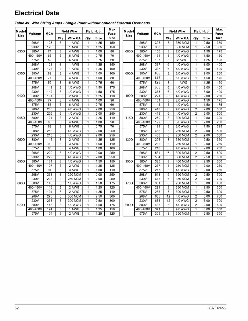
62 CAT 613-2
Electrical Data
Table 49: Wire Sizing Amps - Single Point without optional External Overloads
Qty Wire GA Qty Size Qty Wire GA Qty Size
208V 126 3 1 AWG 1 1.25 150 208V 308 3 350 MCM 1 2.50 350230V 126 3 1 AWG 1 1.25 150 230V 308 3 350 MCM 1 2.50 350380V 71 3 4 AWG 1 1.00 80 380V 150 3 2/0 AWG 1 1.50 175
400-460V 63 3 6 AWG 1 0.75 70 400-460V 131 3 1/0 AWG 1 1.50 150575V 52 3 6 AWG 1 0.75 60 575V 107 3 2 AWG 1 1.25 125
208V 128 3 1 AWG 1 1.25 150 208V 337 6 4/0 AWG 1 3.00 400230V 128 3 1 AWG 1 1.25 150 230V 337 6 4/0 AWG 1 3.00 400
380V 82 3 4 AWG 1 1.00 100 380V 188 3 3/0 AWG 1 2.00 200
400-460V 71 3 4 AWG 1 1.00 80 400-460V 147 3 1/0 AWG 1 1.50 175
575V 52 3 6 AWG 1 0.75 60 575V 128 3 1 AWG 1 1.25 150
208V 142 3 1/0 AWG 1 1.50 175 208V 363 6 4/0 AWG 1 3.00 400230V 142 3 1/0 AWG 1 1.50 175 230V 363 6 4/0 AWG 1 3.00 400380V 101 3 2 AWG 1 1.25 110 380V 221 3 4/0 AWG 1 2.00 250
400-460V 77 3 4 AWG 1 1.00 90 400-460V 161 3 2/0 AWG 1 1.50 175575V 55 3 6 AWG 1 0.75 60 575V 148 3 1/0 AWG 1 1.50 175
208V 205 3 4/0 AWG 1 2.00 250 208V 418 6 4/0 AWG 2 2.00 500230V 205 3 4/0 AWG 1 2.00 250 230V 418 6 4/0 AWG 2 2.00 500380V 101 3 2 AWG 1 1.25 110 380V 260 3 300 MCM 1 2.50 300
400-460V 80 3 4 AWG 1 1.00 90 400-460V 199 3 3/0 AWG 1 2.00 250575V 63 3 6 AWG 1 0.75 70 575V 181 3 3/0 AWG 1 1.50 225
208V 218 3 4/0 AWG 1 2.00 250 208V 466 6 250 MCM 2 2.00 500230V 218 3 4/0 AWG 1 2.00 250 230V 466 6 250 MCM 2 2.00 500380V 115 3 2 AWG 1 1.25 125 380V 295 3 350 MCM 1 2.50 350
400-460V 99 3 3 AWG 1 1.00 110 400-460V 232 3 250 MCM 1 2.00 250575V 85 3 4 AWG 1 1.00 100 575V 210 3 4/0 AWG 1 2.00 250
208V 229 3 4/0 AWG 1 2.00 250 208V 534 6 300 MCM 2 2.50 600230V 229 3 4/0 AWG 1 2.00 250 230V 534 6 300 MCM 2 2.50 600380V 131 3 1/0 AWG 1 1.50 150 380V 325 3 400 MCM 1 2.50 350
400-460V 107 3 2 AWG 1 1.25 125 400-460V 237 3 250 MCM 1 2.00 250575V 94 3 3 AWG 1 1.00 110 575V 217 3 4/0 AWG 1 2.00 250
208V 238 3 250 MCM 1 2.00 250 208V 613 6 350 MCM 2 2.50 700230V 238 3 250 MCM 1 2.00 250 230V 613 6 350 MCM 2 2.50 700380V 145 3 1/0 AWG 1 1.50 175 380V 381 6 250 MCM 1 3.00 400
400-460V 115 3 2 AWG 1 1.25 125 400-460V 291 3 350 MCM 1 2.50 300575V 101 3 2 AWG 1 1.25 110 575V 265 3 300 MCM 1 2.50 300
208V 275 3 300 MCM 1 2.50 300 208V 685 12 4/0 AWG 2 3.00 700230V 275 3 300 MCM 1 2.50 300 230V 685 12 4/0 AWG 2 3.00 700380V 148 3 1/0 AWG 1 1.50 175 380V 433 6 4/0 AWG 2 2.00 500
400-460V 124 3 1 AWG 1 1.25 150 400-460V 341 6 4/0 AWG 1 3.00 350575V 104 3 2 AWG 1 1.25 125 575V 309 3 350 MCM 1 2.50 350
050D
055D
060D
070D
030D
035D
040D
045D
130D
150D
170D
200D
080D
090D
100D
115D
Max Fuse Size
Model Size
Voltage MCAField Wire Field Hub. Model
SizeVoltage MCA
Max Fuse Size
Field Wire Field Hub.
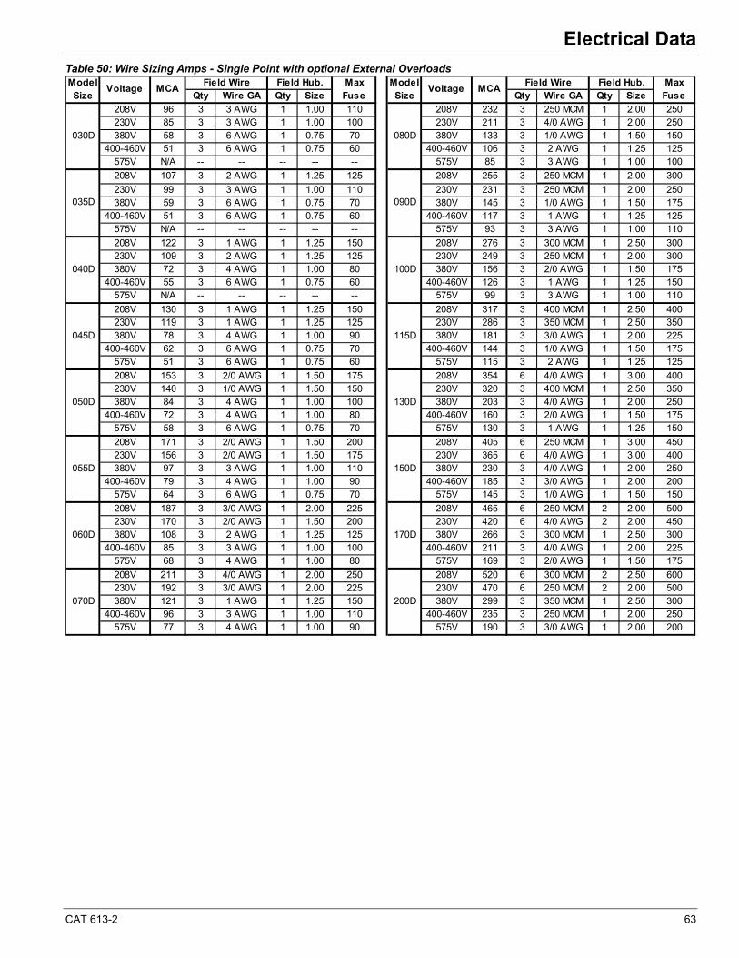
CAT 613-2 63
Electrical Data
Table 50: Wire Sizing Amps - Single Point with optional External Overloads
Qty Wire GA Qty Size Qty Wire GA Qty Size
208V 96 3 3 AWG 1 1.00 110 208V 232 3 250 MCM 1 2.00 250230V 85 3 3 AWG 1 1.00 100 230V 211 3 4/0 AWG 1 2.00 250380V 58 3 6 AWG 1 0.75 70 380V 133 3 1/0 AWG 1 1.50 150
400-460V 51 3 6 AWG 1 0.75 60 400-460V 106 3 2 AWG 1 1.25 125575V N/A -- -- -- -- -- 575V 85 3 3 AWG 1 1.00 100
208V 107 3 2 AWG 1 1.25 125 208V 255 3 250 MCM 1 2.00 300
230V 99 3 3 AWG 1 1.00 110 230V 231 3 250 MCM 1 2.00 250380V 59 3 6 AWG 1 0.75 70 380V 145 3 1/0 AWG 1 1.50 175
400-460V 51 3 6 AWG 1 0.75 60 400-460V 117 3 1 AWG 1 1.25 125575V N/A -- -- -- -- -- 575V 93 3 3 AWG 1 1.00 110
208V 122 3 1 AWG 1 1.25 150 208V 276 3 300 MCM 1 2.50 300230V 109 3 2 AWG 1 1.25 125 230V 249 3 250 MCM 1 2.00 300380V 72 3 4 AWG 1 1.00 80 380V 156 3 2/0 AWG 1 1.50 175
400-460V 55 3 6 AWG 1 0.75 60 400-460V 126 3 1 AWG 1 1.25 150575V N/A -- -- -- -- -- 575V 99 3 3 AWG 1 1.00 110
208V 130 3 1 AWG 1 1.25 150 208V 317 3 400 MCM 1 2.50 400230V 119 3 1 AWG 1 1.25 125 230V 286 3 350 MCM 1 2.50 350380V 78 3 4 AWG 1 1.00 90 380V 181 3 3/0 AWG 1 2.00 225
400-460V 62 3 6 AWG 1 0.75 70 400-460V 144 3 1/0 AWG 1 1.50 175575V 51 3 6 AWG 1 0.75 60 575V 115 3 2 AWG 1 1.25 125
208V 153 3 2/0 AWG 1 1.50 175 208V 354 6 4/0 AWG 1 3.00 400230V 140 3 1/0 AWG 1 1.50 150 230V 320 3 400 MCM 1 2.50 350380V 84 3 4 AWG 1 1.00 100 380V 203 3 4/0 AWG 1 2.00 250
400-460V 72 3 4 AWG 1 1.00 80 400-460V 160 3 2/0 AWG 1 1.50 175575V 58 3 6 AWG 1 0.75 70 575V 130 3 1 AWG 1 1.25 150
208V 171 3 2/0 AWG 1 1.50 200 208V 405 6 250 MCM 1 3.00 450230V 156 3 2/0 AWG 1 1.50 175 230V 365 6 4/0 AWG 1 3.00 400380V 97 3 3 AWG 1 1.00 110 380V 230 3 4/0 AWG 1 2.00 250
400-460V 79 3 4 AWG 1 1.00 90 400-460V 185 3 3/0 AWG 1 2.00 200575V 64 3 6 AWG 1 0.75 70 575V 145 3 1/0 AWG 1 1.50 150
208V 187 3 3/0 AWG 1 2.00 225 208V 465 6 250 MCM 2 2.00 500230V 170 3 2/0 AWG 1 1.50 200 230V 420 6 4/0 AWG 2 2.00 450380V 108 3 2 AWG 1 1.25 125 380V 266 3 300 MCM 1 2.50 300
400-460V 85 3 3 AWG 1 1.00 100 400-460V 211 3 4/0 AWG 1 2.00 225575V 68 3 4 AWG 1 1.00 80 575V 169 3 2/0 AWG 1 1.50 175
208V 211 3 4/0 AWG 1 2.00 250 208V 520 6 300 MCM 2 2.50 600230V 192 3 3/0 AWG 1 2.00 225 230V 470 6 250 MCM 2 2.00 500380V 121 3 1 AWG 1 1.25 150 380V 299 3 350 MCM 1 2.50 300
400-460V 96 3 3 AWG 1 1.00 110 400-460V 235 3 250 MCM 1 2.00 250575V 77 3 4 AWG 1 1.00 90 575V 190 3 3/0 AWG 1 2.00 200
Max Fuse
030D
035D
040D
Model Size
Voltage MCAMax Fuse
Field Wire Field Hub. Field Wire Field Hub.Model Size
Voltage MCA
070D
080D
090D
100D
115D
130D
150D
170D
200D
045D
050D
055D
060D
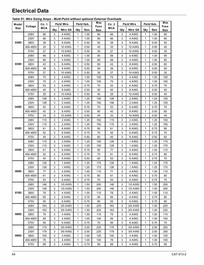
64 CAT 613-2
Electrical Data
Table 51: Wire Sizing Amps - Multi-Point without optional External Overloads
Qty Wire GA Qty Size Qty Wire GA Qty Size
208V 66 3 4 AWG 1 1.00 90 66 3 4 AWG 1 1.00 90
230V 66 3 4 AWG 1 1.00 90 66 3 4 AWG 1 1.00 90
380V 38 3 8 AWG 1 0.50 50 38 3 8 AWG 1 0.50 50
400-460V 33 3 10 AWG 1 0.50 45 33 3 10 AWG 1 0.50 45
575V 27 3 10 AWG 1 0.50 35 27 3 10 AWG 1 0.50 35
208V 68 3 4 AWG 1 1.00 90 68 3 4 AWG 1 1.00 90
230V 68 3 4 AWG 1 1.00 90 68 3 4 AWG 1 1.00 90
380V 43 3 8 AWG 1 0.50 60 43 3 8 AWG 1 0.50 60
400-460V 38 3 8 AWG 1 0.50 50 38 3 8 AWG 1 0.50 50
575V 27 3 10 AWG 1 0.50 35 27 3 10 AWG 1 0.50 35
208V 75 3 4 AWG 1 1.00 100 75 3 4 AWG 1 1.00 100
230V 75 3 4 AWG 1 1.00 100 75 3 4 AWG 1 1.00 100
380V 53 3 6 AWG 1 0.75 70 53 3 6 AWG 1 0.75 70
400-460V 40 3 8 AWG 1 0.50 50 40 3 8 AWG 1 0.50 50
575V 29 3 10 AWG 1 0.50 40 29 3 10 AWG 1 0.50 40
208V 108 3 2 AWG 1 1.25 150 108 3 2 AWG 1 1.25 150
230V 108 3 2 AWG 1 1.25 150 108 3 2 AWG 1 1.25 150
380V 53 3 6 AWG 1 0.75 70 53 3 6 AWG 1 0.75 70
400-460V 42 3 8 AWG 1 0.50 60 42 3 8 AWG 1 0.50 60
575V 33 3 10 AWG 1 0.50 45 33 3 10 AWG 1 0.50 45
208V 115 3 2 AWG 1 1.25 150 115 3 2 AWG 1 1.25 150
230V 115 3 2 AWG 1 1.25 150 115 3 2 AWG 1 1.25 150
380V 61 3 6 AWG 1 0.75 80 61 3 6 AWG 1 0.75 80
400-460V 52 3 6 AWG 1 0.75 70 52 3 6 AWG 1 0.75 70
575V 45 3 8 AWG 1 0.50 60 45 3 8 AWG 1 0.50 60
208V 115 3 2 AWG 1 1.25 150 126 3 1 AWG 1 1.25 175
230V 115 3 2 AWG 1 1.25 150 126 3 1 AWG 1 1.25 175
380V 61 3 6 AWG 1 0.75 80 77 3 4 AWG 1 1.00 110
400-460V 52 3 6 AWG 1 0.75 70 61 3 6 AWG 1 0.75 80
575V 45 3 8 AWG 1 0.50 60 53 3 6 AWG 1 0.75 70
208V 126 3 1 AWG 1 1.25 175 126 3 1 AWG 1 1.25 175
230V 126 3 1 AWG 1 1.25 175 126 3 1 AWG 1 1.25 175
380V 77 3 4 AWG 1 1.00 110 77 3 4 AWG 1 1.00 110
400-460V 61 3 6 AWG 1 0.75 80 61 3 6 AWG 1 0.75 80
575V 53 3 6 AWG 1 0.75 70 53 3 6 AWG 1 0.75 70
208V 146 3 1/0 AWG 1 1.50 200 146 3 1/0 AWG 1 1.50 200
230V 146 3 1/0 AWG 1 1.50 200 146 3 1/0 AWG 1 1.50 200
380V 78 3 4 AWG 1 1.00 110 78 3 4 AWG 1 1.00 110
400-460V 65 3 6 AWG 1 0.75 90 65 3 6 AWG 1 0.75 90
575V 55 3 6 AWG 1 0.75 80 55 3 6 AWG 1 0.75 80
208V 163 3 2/0 AWG 1 1.50 225 163 3 2/0 AWG 1 1.50 225
230V 163 3 2/0 AWG 1 1.50 225 163 3 2/0 AWG 1 1.50 225
380V 79 3 4 AWG 1 1.00 110 79 3 4 AWG 1 1.00 110
400-460V 69 3 4 AWG 1 1.00 100 69 3 4 AWG 1 1.00 100
575V 56 3 6 AWG 1 0.75 70 56 3 6 AWG 1 0.75 70
208V 179 3 3/0 AWG 1 2.00 225 179 3 3/0 AWG 1 2.00 250
230V 179 3 3/0 AWG 1 2.00 225 179 3 3/0 AWG 1 2.00 250
380V 100 3 3 AWG 1 1.00 125 100 3 3 AWG 1 1.00 125
400-460V 78 3 4 AWG 1 1.00 100 78 3 4 AWG 1 1.00 100
575V 68 3 4 AWG 1 0.75 90 68 3 4 AWG 1 0.75 90
Field Wire Field Hub.Model Size
Voltage
060D
070D
080D
090D
Field Hub. Max Fuse Size
030D
035D
Field WireCir. 1MCA
Max Fuse Size
050D
055D
040D
045D
Cir. 2MCA
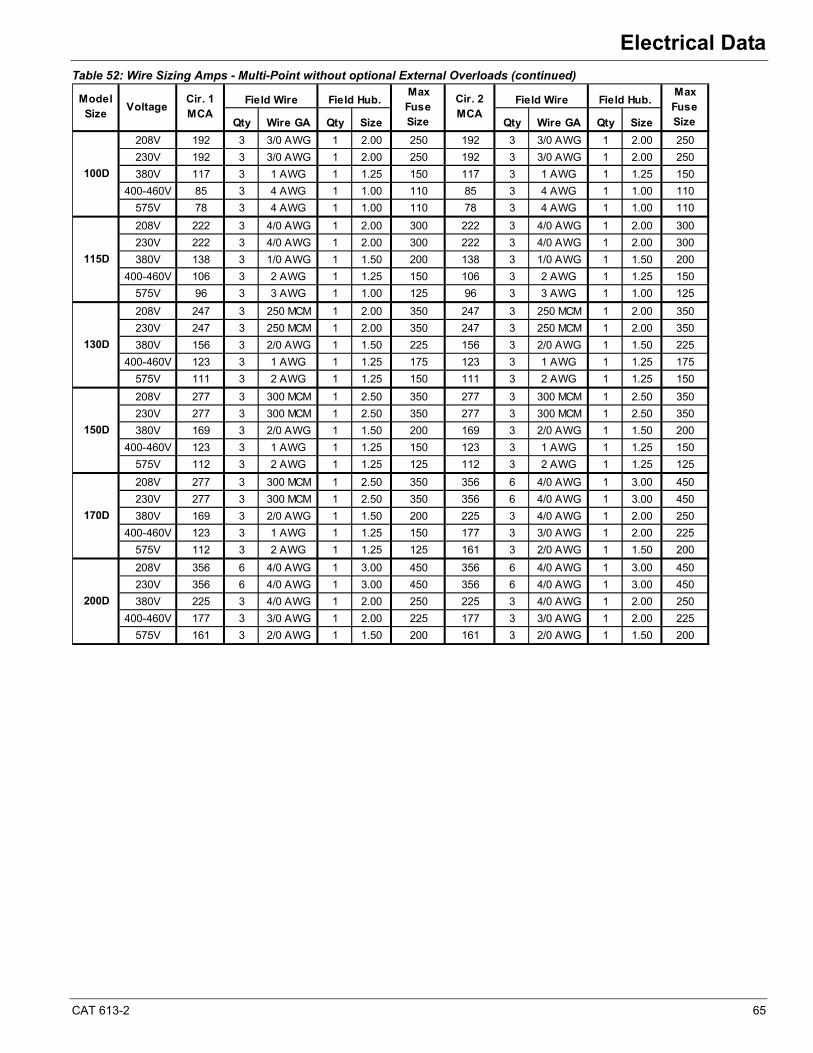
CAT 613-2 65
Electrical Data
Table 52: Wire Sizing Amps - Multi-Point without optional External Overloads (continued)
Qty Wire GA Qty Size Qty Wire GA Qty Size
208V 192 3 3/0 AWG 1 2.00 250 192 3 3/0 AWG 1 2.00 250
230V 192 3 3/0 AWG 1 2.00 250 192 3 3/0 AWG 1 2.00 250
380V 117 3 1 AWG 1 1.25 150 117 3 1 AWG 1 1.25 150
400-460V 85 3 4 AWG 1 1.00 110 85 3 4 AWG 1 1.00 110
575V 78 3 4 AWG 1 1.00 110 78 3 4 AWG 1 1.00 110
208V 222 3 4/0 AWG 1 2.00 300 222 3 4/0 AWG 1 2.00 300
230V 222 3 4/0 AWG 1 2.00 300 222 3 4/0 AWG 1 2.00 300
380V 138 3 1/0 AWG 1 1.50 200 138 3 1/0 AWG 1 1.50 200
400-460V 106 3 2 AWG 1 1.25 150 106 3 2 AWG 1 1.25 150
575V 96 3 3 AWG 1 1.00 125 96 3 3 AWG 1 1.00 125
208V 247 3 250 MCM 1 2.00 350 247 3 250 MCM 1 2.00 350
230V 247 3 250 MCM 1 2.00 350 247 3 250 MCM 1 2.00 350
380V 156 3 2/0 AWG 1 1.50 225 156 3 2/0 AWG 1 1.50 225
400-460V 123 3 1 AWG 1 1.25 175 123 3 1 AWG 1 1.25 175
575V 111 3 2 AWG 1 1.25 150 111 3 2 AWG 1 1.25 150
208V 277 3 300 MCM 1 2.50 350 277 3 300 MCM 1 2.50 350
230V 277 3 300 MCM 1 2.50 350 277 3 300 MCM 1 2.50 350
380V 169 3 2/0 AWG 1 1.50 200 169 3 2/0 AWG 1 1.50 200
400-460V 123 3 1 AWG 1 1.25 150 123 3 1 AWG 1 1.25 150
575V 112 3 2 AWG 1 1.25 125 112 3 2 AWG 1 1.25 125
208V 277 3 300 MCM 1 2.50 350 356 6 4/0 AWG 1 3.00 450
230V 277 3 300 MCM 1 2.50 350 356 6 4/0 AWG 1 3.00 450
380V 169 3 2/0 AWG 1 1.50 200 225 3 4/0 AWG 1 2.00 250
400-460V 123 3 1 AWG 1 1.25 150 177 3 3/0 AWG 1 2.00 225
575V 112 3 2 AWG 1 1.25 125 161 3 2/0 AWG 1 1.50 200
208V 356 6 4/0 AWG 1 3.00 450 356 6 4/0 AWG 1 3.00 450
230V 356 6 4/0 AWG 1 3.00 450 356 6 4/0 AWG 1 3.00 450
380V 225 3 4/0 AWG 1 2.00 250 225 3 4/0 AWG 1 2.00 250
400-460V 177 3 3/0 AWG 1 2.00 225 177 3 3/0 AWG 1 2.00 225
575V 161 3 2/0 AWG 1 1.50 200 161 3 2/0 AWG 1 1.50 200
170D
200D
Max Fuse Size
VoltageCir. 1MCA
Max Fuse Size
Cir. 2MCA
Field Wire Field Hub.
100D
115D
Model Size
130D
Field Wire Field Hub.
150D
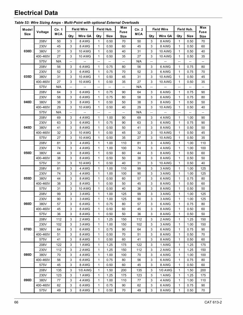
66 CAT 613-2
Electrical Data
Table 53: Wire Sizing Amps - Multi-Point with optional External Overloads
Qty Wire GA Qty Size Qty Wire GA Qty Size
208V 50 3 8 AWG 1 0.50 70 50 3 8 AWG 1 0.50 70
230V 45 3 8 AWG 1 0.50 60 45 3 8 AWG 1 0.50 60
380V 31 3 10 AWG 1 0.50 40 31 3 10 AWG 1 0.50 40
400-460V 27 3 10 AWG 1 0.50 35 27 3 10 AWG 1 0.50 35
575V N/A -- -- -- -- -- N/A -- -- -- -- --
208V 56 3 6 AWG 1 0.75 80 56 3 6 AWG 1 0.75 80
230V 52 3 6 AWG 1 0.75 70 52 3 6 AWG 1 0.75 70
380V 31 3 10 AWG 1 0.50 45 31 3 10 AWG 1 0.50 45
400-460V 27 3 10 AWG 1 0.50 35 27 3 10 AWG 1 0.50 35
575V N/A -- -- -- -- -- N/A -- -- -- -- --
208V 64 3 6 AWG 1 0.75 90 64 3 6 AWG 1 0.75 90
230V 58 3 6 AWG 1 0.75 80 58 3 6 AWG 1 0.75 80
380V 38 3 8 AWG 1 0.50 50 38 3 8 AWG 1 0.50 50
400-460V 29 3 10 AWG 1 0.50 40 29 3 10 AWG 1 0.50 40
575V N/A -- -- -- -- -- N/A -- -- -- -- --
208V 69 3 4 AWG 1 1.00 90 69 3 4 AWG 1 1.00 90
230V 63 3 6 AWG 1 0.75 90 63 3 6 AWG 1 0.75 90
380V 41 3 8 AWG 1 0.50 50 41 3 8 AWG 1 0.50 50
400-460V 32 3 10 AWG 1 0.50 45 32 3 10 AWG 1 0.50 45
575V 27 3 10 AWG 1 0.50 35 27 3 10 AWG 1 0.50 35
208V 81 3 4 AWG 1 1.00 110 81 3 4 AWG 1 1.00 110
230V 74 3 4 AWG 1 1.00 100 74 3 4 AWG 1 1.00 100
380V 44 3 8 AWG 1 0.50 60 44 3 8 AWG 1 0.50 60
400-460V 38 3 8 AWG 1 0.50 50 38 3 8 AWG 1 0.50 50
575V 31 3 10 AWG 1 0.50 40 31 3 10 AWG 1 0.50 40
208V 81 3 4 AWG 1 1.00 110 99 3 3 AWG 1 1.00 125
230V 74 3 4 AWG 1 1.00 100 90 3 3 AWG 1 1.00 125
380V 44 3 8 AWG 1 0.50 60 57 3 6 AWG 1 0.75 80
400-460V 38 3 8 AWG 1 0.50 50 45 3 8 AWG 1 0.50 60
575V 31 3 10 AWG 1 0.50 40 36 3 8 AWG 1 0.50 50
208V 99 3 3 AWG 1 1.00 125 99 3 3 AWG 1 1.00 125
230V 90 3 3 AWG 1 1.00 125 90 3 3 AWG 1 1.00 125
380V 57 3 6 AWG 1 0.75 80 57 3 6 AWG 1 0.75 80
400-460V 45 3 8 AWG 1 0.50 60 45 3 8 AWG 1 0.50 60
575V 36 3 8 AWG 1 0.50 50 36 3 8 AWG 1 0.50 50
208V 112 3 2 AWG 1 1.25 150 112 3 2 AWG 1 1.25 150
230V 102 3 3 AWG 1 1.00 150 102 3 3 AWG 1 1.00 150
380V 64 3 6 AWG 1 0.75 90 64 3 6 AWG 1 0.75 90
400-460V 51 3 8 AWG 1 0.50 70 51 3 8 AWG 1 0.50 70
575V 41 3 8 AWG 1 0.50 60 41 3 8 AWG 1 0.50 60
208V 122 3 1 AWG 1 1.25 175 122 3 1 AWG 1 1.25 175
230V 112 3 2 AWG 1 1.25 150 112 3 2 AWG 1 1.25 150
380V 70 3 4 AWG 1 1.00 100 70 3 4 AWG 1 1.00 100
400-460V 56 3 6 AWG 1 0.75 80 56 3 6 AWG 1 0.75 80
575V 45 3 8 AWG 1 0.50 60 45 3 8 AWG 1 0.50 60
208V 135 3 1/0 AWG 1 1.50 200 135 3 1/0 AWG 1 1.50 200
230V 123 3 1 AWG 1 1.25 175 123 3 1 AWG 1 1.25 175
380V 77 3 4 AWG 1 1.00 110 77 3 4 AWG 1 1.00 110
400-460V 62 3 6 AWG 1 0.75 90 62 3 6 AWG 1 0.75 90
575V 49 3 8 AWG 1 0.50 70 49 3 8 AWG 1 0.50 70
Field Wire Field Hub. Max Fuse Size
Cir. 2MCA
Field Hub.Model Size
VoltageCir. 1MCA
060D
070D
090D
Field Wire
030D
035D
040D
080D
Max Fuse Size
045D
050D
055D
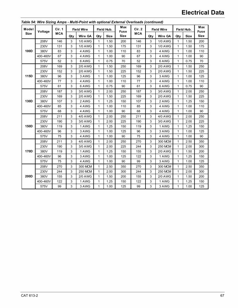
CAT 613-2 67
Electrical Data
Table 54: Wire Sizing Amps - Multi-Point with optional External Overloads (continued)
Qty Wire GA Qty Size Qty Wire GA Qty Size
208V 146 3 1/0 AWG 1 1.50 200 146 3 1/0 AWG 1 1.50 200
230V 131 3 1/0 AWG 1 1.50 175 131 3 1/0 AWG 1 1.50 175
380V 83 3 4 AWG 1 1.00 110 83 3 4 AWG 1 1.00 110
400-460V 67 3 4 AWG 1 1.00 90 67 3 4 AWG 1 1.00 90
575V 52 3 6 AWG 1 0.75 70 52 3 6 AWG 1 0.75 70
208V 169 3 2/0 AWG 1 1.50 250 169 3 2/0 AWG 1 1.50 250
230V 152 3 2/0 AWG 1 1.50 225 152 3 2/0 AWG 1 1.50 225
380V 96 3 3 AWG 1 1.00 125 96 3 3 AWG 1 1.00 125
400-460V 77 3 4 AWG 1 1.00 110 77 3 4 AWG 1 1.00 110
575V 61 3 6 AWG 1 0.75 90 61 3 6 AWG 1 0.75 90
208V 187 3 3/0 AWG 1 2.00 250 187 3 3/0 AWG 1 2.00 250
230V 169 3 2/0 AWG 1 1.50 225 169 3 2/0 AWG 1 1.50 225
380V 107 3 2 AWG 1 1.25 150 107 3 2 AWG 1 1.25 150
400-460V 85 3 4 AWG 1 1.00 110 85 3 4 AWG 1 1.00 110
575V 68 3 4 AWG 1 1.00 90 68 3 4 AWG 1 1.00 90
208V 211 3 4/0 AWG 1 2.00 250 211 3 4/0 AWG 1 2.00 250
230V 190 3 3/0 AWG 1 2.00 225 190 3 3/0 AWG 1 2.00 225
380V 119 3 1 AWG 1 1.25 150 119 3 1 AWG 1 1.25 150
400-460V 96 3 3 AWG 1 1.00 125 96 3 3 AWG 1 1.00 125
575V 75 3 4 AWG 1 1.00 90 75 3 4 AWG 1 1.00 90
208V 211 3 4/0 AWG 1 2.00 250 270 3 300 MCM 1 2.50 350
230V 190 3 3/0 AWG 1 2.00 225 244 3 250 MCM 1 2.00 300
380V 119 3 1 AWG 1 1.25 150 155 3 2/0 AWG 1 1.50 200
400-460V 96 3 3 AWG 1 1.00 125 122 3 1 AWG 1 1.25 150
575V 75 3 4 AWG 1 1.00 90 99 3 3 AWG 1 1.00 125
208V 270 3 300 MCM 1 2.50 350 270 3 300 MCM 1 2.50 350
230V 244 3 250 MCM 1 2.00 300 244 3 250 MCM 1 2.00 300
380V 155 3 2/0 AWG 1 1.50 200 155 3 2/0 AWG 1 1.50 200
400-460V 122 3 1 AWG 1 1.25 150 122 3 1 AWG 1 1.25 150
575V 99 3 3 AWG 1 1.00 125 99 3 3 AWG 1 1.00 125
150D
170D
200D
Field Hub.
130D
Field WireModel Size
VoltageCir. 1MCA
Field WireField Hub.Max Fuse Size
Cir. 2MCA
100D
115D
Max Fuse Size
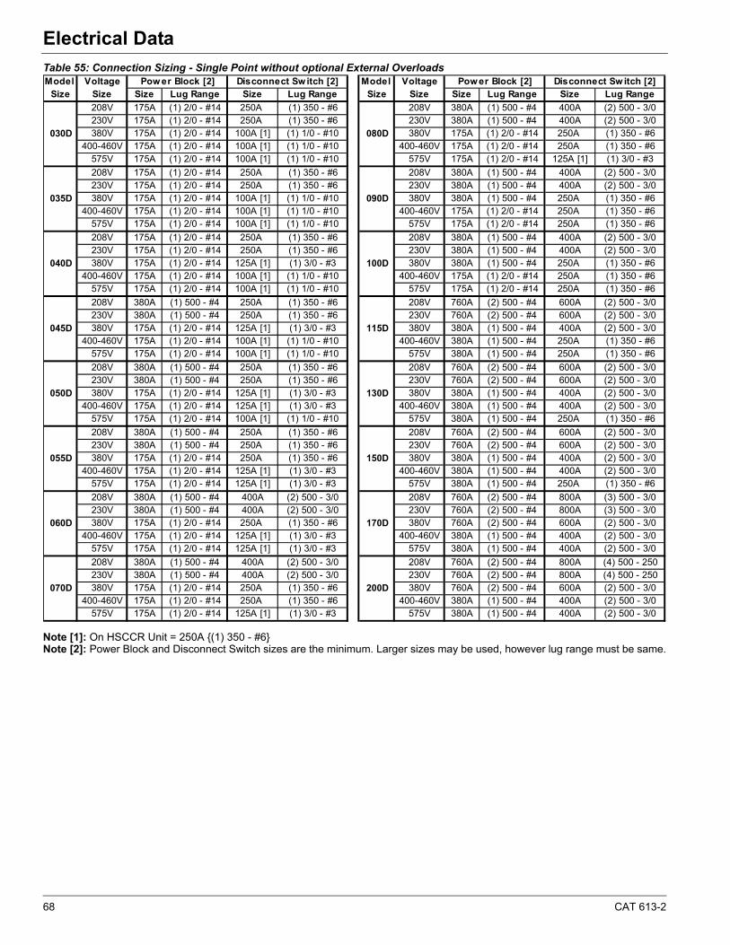
68 CAT 613-2
Electrical Data
Table 55: Connection Sizing - Single Point without optional External Overloads
Note [1]: On HSCCR Unit = 250A {(1) 350 - #6}Note [2]: Power Block and Disconnect Switch sizes are the minimum. Larger sizes may be used, however lug range must be same.
Model Voltage Model VoltageSize Size Size Lug Range Size Lug Range Size Size Size Lug Range Size Lug Range
208V 175A (1) 2/0 - #14 250A (1) 350 - #6 208V 380A (1) 500 - #4 400A (2) 500 - 3/0230V 175A (1) 2/0 - #14 250A (1) 350 - #6 230V 380A (1) 500 - #4 400A (2) 500 - 3/0380V 175A (1) 2/0 - #14 100A [1] (1) 1/0 - #10 380V 175A (1) 2/0 - #14 250A (1) 350 - #6
400-460V 175A (1) 2/0 - #14 100A [1] (1) 1/0 - #10 400-460V 175A (1) 2/0 - #14 250A (1) 350 - #6575V 175A (1) 2/0 - #14 100A [1] (1) 1/0 - #10 575V 175A (1) 2/0 - #14 125A [1] (1) 3/0 - #3
208V 175A (1) 2/0 - #14 250A (1) 350 - #6 208V 380A (1) 500 - #4 400A (2) 500 - 3/0230V 175A (1) 2/0 - #14 250A (1) 350 - #6 230V 380A (1) 500 - #4 400A (2) 500 - 3/0380V 175A (1) 2/0 - #14 100A [1] (1) 1/0 - #10 380V 380A (1) 500 - #4 250A (1) 350 - #6
400-460V 175A (1) 2/0 - #14 100A [1] (1) 1/0 - #10 400-460V 175A (1) 2/0 - #14 250A (1) 350 - #6575V 175A (1) 2/0 - #14 100A [1] (1) 1/0 - #10 575V 175A (1) 2/0 - #14 250A (1) 350 - #6
208V 175A (1) 2/0 - #14 250A (1) 350 - #6 208V 380A (1) 500 - #4 400A (2) 500 - 3/0230V 175A (1) 2/0 - #14 250A (1) 350 - #6 230V 380A (1) 500 - #4 400A (2) 500 - 3/0380V 175A (1) 2/0 - #14 125A [1] (1) 3/0 - #3 380V 380A (1) 500 - #4 250A (1) 350 - #6
400-460V 175A (1) 2/0 - #14 100A [1] (1) 1/0 - #10 400-460V 175A (1) 2/0 - #14 250A (1) 350 - #6575V 175A (1) 2/0 - #14 100A [1] (1) 1/0 - #10 575V 175A (1) 2/0 - #14 250A (1) 350 - #6
208V 380A (1) 500 - #4 250A (1) 350 - #6 208V 760A (2) 500 - #4 600A (2) 500 - 3/0230V 380A (1) 500 - #4 250A (1) 350 - #6 230V 760A (2) 500 - #4 600A (2) 500 - 3/0380V 175A (1) 2/0 - #14 125A [1] (1) 3/0 - #3 380V 380A (1) 500 - #4 400A (2) 500 - 3/0
400-460V 175A (1) 2/0 - #14 100A [1] (1) 1/0 - #10 400-460V 380A (1) 500 - #4 250A (1) 350 - #6575V 175A (1) 2/0 - #14 100A [1] (1) 1/0 - #10 575V 380A (1) 500 - #4 250A (1) 350 - #6
208V 380A (1) 500 - #4 250A (1) 350 - #6 208V 760A (2) 500 - #4 600A (2) 500 - 3/0230V 380A (1) 500 - #4 250A (1) 350 - #6 230V 760A (2) 500 - #4 600A (2) 500 - 3/0380V 175A (1) 2/0 - #14 125A [1] (1) 3/0 - #3 380V 380A (1) 500 - #4 400A (2) 500 - 3/0
400-460V 175A (1) 2/0 - #14 125A [1] (1) 3/0 - #3 400-460V 380A (1) 500 - #4 400A (2) 500 - 3/0575V 175A (1) 2/0 - #14 100A [1] (1) 1/0 - #10 575V 380A (1) 500 - #4 250A (1) 350 - #6
208V 380A (1) 500 - #4 250A (1) 350 - #6 208V 760A (2) 500 - #4 600A (2) 500 - 3/0230V 380A (1) 500 - #4 250A (1) 350 - #6 230V 760A (2) 500 - #4 600A (2) 500 - 3/0380V 175A (1) 2/0 - #14 250A (1) 350 - #6 380V 380A (1) 500 - #4 400A (2) 500 - 3/0
400-460V 175A (1) 2/0 - #14 125A [1] (1) 3/0 - #3 400-460V 380A (1) 500 - #4 400A (2) 500 - 3/0575V 175A (1) 2/0 - #14 125A [1] (1) 3/0 - #3 575V 380A (1) 500 - #4 250A (1) 350 - #6
208V 380A (1) 500 - #4 400A (2) 500 - 3/0 208V 760A (2) 500 - #4 800A (3) 500 - 3/0230V 380A (1) 500 - #4 400A (2) 500 - 3/0 230V 760A (2) 500 - #4 800A (3) 500 - 3/0380V 175A (1) 2/0 - #14 250A (1) 350 - #6 380V 760A (2) 500 - #4 600A (2) 500 - 3/0
400-460V 175A (1) 2/0 - #14 125A [1] (1) 3/0 - #3 400-460V 380A (1) 500 - #4 400A (2) 500 - 3/0575V 175A (1) 2/0 - #14 125A [1] (1) 3/0 - #3 575V 380A (1) 500 - #4 400A (2) 500 - 3/0
208V 380A (1) 500 - #4 400A (2) 500 - 3/0 208V 760A (2) 500 - #4 800A (4) 500 - 250230V 380A (1) 500 - #4 400A (2) 500 - 3/0 230V 760A (2) 500 - #4 800A (4) 500 - 250380V 175A (1) 2/0 - #14 250A (1) 350 - #6 380V 760A (2) 500 - #4 600A (2) 500 - 3/0
400-460V 175A (1) 2/0 - #14 250A (1) 350 - #6 400-460V 380A (1) 500 - #4 400A (2) 500 - 3/0575V 175A (1) 2/0 - #14 125A [1] (1) 3/0 - #3 575V 380A (1) 500 - #4 400A (2) 500 - 3/0
055D
060D
070D
150D
170D
200D
030D
035D
040D
045D
050D
Pow er Block [2] Disconnect Sw itch [2]Pow er Block [2] Disconnect Switch [2]
080D
090D
100D
115D
130D
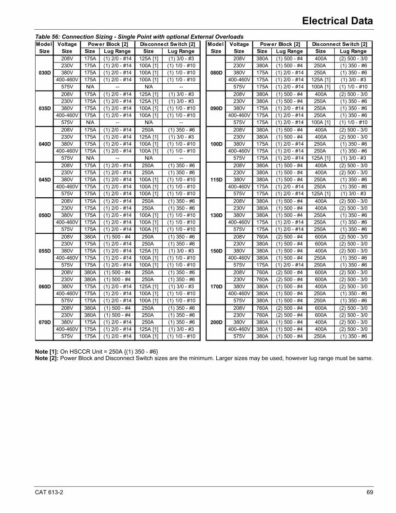
CAT 613-2 69
Electrical Data
Table 56: Connection Sizing - Single Point with optional External Overloads
Note [1]: On HSCCR Unit = 250A {(1) 350 - #6}Note [2]: Power Block and Disconnect Switch sizes are the minimum. Larger sizes may be used, however lug range must be same.
Model Voltage Model VoltageSize Size Size Lug Range Size Lug Range Size Size Size Lug Range Size Lug Range
208V 175A (1) 2/0 - #14 125A [1] (1) 3/0 - #3 208V 380A (1) 500 - #4 400A (2) 500 - 3/0230V 175A (1) 2/0 - #14 100A [1] (1) 1/0 - #10 230V 380A (1) 500 - #4 250A (1) 350 - #6380V 175A (1) 2/0 - #14 100A [1] (1) 1/0 - #10 380V 175A (1) 2/0 - #14 250A (1) 350 - #6
400-460V 175A (1) 2/0 - #14 100A [1] (1) 1/0 - #10 400-460V 175A (1) 2/0 - #14 125A [1] (1) 3/0 - #3575V N/A -- N/A -- 575V 175A (1) 2/0 - #14 100A [1] (1) 1/0 - #10
208V 175A (1) 2/0 - #14 125A [1] (1) 3/0 - #3 208V 380A (1) 500 - #4 400A (2) 500 - 3/0230V 175A (1) 2/0 - #14 125A [1] (1) 3/0 - #3 230V 380A (1) 500 - #4 250A (1) 350 - #6380V 175A (1) 2/0 - #14 100A [1] (1) 1/0 - #10 380V 175A (1) 2/0 - #14 250A (1) 350 - #6
400-460V 175A (1) 2/0 - #14 100A [1] (1) 1/0 - #10 400-460V 175A (1) 2/0 - #14 250A (1) 350 - #6575V N/A -- N/A -- 575V 175A (1) 2/0 - #14 100A [1] (1) 1/0 - #10
208V 175A (1) 2/0 - #14 250A (1) 350 - #6 208V 380A (1) 500 - #4 400A (2) 500 - 3/0230V 175A (1) 2/0 - #14 125A [1] (1) 3/0 - #3 230V 380A (1) 500 - #4 400A (2) 500 - 3/0380V 175A (1) 2/0 - #14 100A [1] (1) 1/0 - #10 380V 175A (1) 2/0 - #14 250A (1) 350 - #6
400-460V 175A (1) 2/0 - #14 100A [1] (1) 1/0 - #10 400-460V 175A (1) 2/0 - #14 250A (1) 350 - #6575V N/A -- N/A -- 575V 175A (1) 2/0 - #14 125A [1] (1) 3/0 - #3
208V 175A (1) 2/0 - #14 250A (1) 350 - #6 208V 380A (1) 500 - #4 400A (2) 500 - 3/0230V 175A (1) 2/0 - #14 250A (1) 350 - #6 230V 380A (1) 500 - #4 400A (2) 500 - 3/0380V 175A (1) 2/0 - #14 100A [1] (1) 1/0 - #10 380V 380A (1) 500 - #4 250A (1) 350 - #6
400-460V 175A (1) 2/0 - #14 100A [1] (1) 1/0 - #10 400-460V 175A (1) 2/0 - #14 250A (1) 350 - #6575V 175A (1) 2/0 - #14 100A [1] (1) 1/0 - #10 575V 175A (1) 2/0 - #14 125A [1] (1) 3/0 - #3
208V 175A (1) 2/0 - #14 250A (1) 350 - #6 208V 380A (1) 500 - #4 400A (2) 500 - 3/0230V 175A (1) 2/0 - #14 250A (1) 350 - #6 230V 380A (1) 500 - #4 400A (2) 500 - 3/0380V 175A (1) 2/0 - #14 100A [1] (1) 1/0 - #10 380V 380A (1) 500 - #4 250A (1) 350 - #6
400-460V 175A (1) 2/0 - #14 100A [1] (1) 1/0 - #10 400-460V 175A (1) 2/0 - #14 250A (1) 350 - #6575V 175A (1) 2/0 - #14 100A [1] (1) 1/0 - #10 575V 175A (1) 2/0 - #14 250A (1) 350 - #6
208V 380A (1) 500 - #4 250A (1) 350 - #6 208V 760A (2) 500 - #4 600A (2) 500 - 3/0230V 175A (1) 2/0 - #14 250A (1) 350 - #6 230V 380A (1) 500 - #4 600A (2) 500 - 3/0380V 175A (1) 2/0 - #14 125A [1] (1) 3/0 - #3 380V 380A (1) 500 - #4 400A (2) 500 - 3/0
400-460V 175A (1) 2/0 - #14 100A [1] (1) 1/0 - #10 400-460V 380A (1) 500 - #4 250A (1) 350 - #6575V 175A (1) 2/0 - #14 100A [1] (1) 1/0 - #10 575V 175A (1) 2/0 - #14 250A (1) 350 - #6
208V 380A (1) 500 - #4 250A (1) 350 - #6 208V 760A (2) 500 - #4 600A (2) 500 - 3/0230V 380A (1) 500 - #4 250A (1) 350 - #6 230V 760A (2) 500 - #4 600A (2) 500 - 3/0380V 175A (1) 2/0 - #14 125A [1] (1) 3/0 - #3 380V 380A (1) 500 - #4 400A (2) 500 - 3/0
400-460V 175A (1) 2/0 - #14 100A [1] (1) 1/0 - #10 400-460V 380A (1) 500 - #4 250A (1) 350 - #6575V 175A (1) 2/0 - #14 100A [1] (1) 1/0 - #10 575V 380A (1) 500 - #4 250A (1) 350 - #6
208V 380A (1) 500 - #4 250A (1) 350 - #6 208V 760A (2) 500 - #4 600A (2) 500 - 3/0230V 380A (1) 500 - #4 250A (1) 350 - #6 230V 760A (2) 500 - #4 600A (2) 500 - 3/0380V 175A (1) 2/0 - #14 250A (1) 350 - #6 380V 380A (1) 500 - #4 400A (2) 500 - 3/0
400-460V 175A (1) 2/0 - #14 125A [1] (1) 3/0 - #3 400-460V 380A (1) 500 - #4 400A (2) 500 - 3/0575V 175A (1) 2/0 - #14 100A [1] (1) 1/0 - #10 575V 380A (1) 500 - #4 250A (1) 350 - #6
090D
100D
115D
130D
150D
170D
200D
030D
035D
040D
045D
050D
055D
060D
070D
080D
Power Block [2] Disconnect Switch [2]Power Block [2] Disconnect Switch [2]
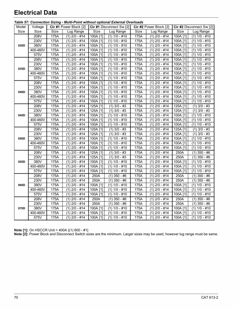
70 CAT 613-2
Electrical Data
Table 57: Connection Sizing - Multi-Point without optional External Overloads
Note [1]: On HSCCR Unit = 400A {(1) 600 - #1}Note [2]: Power Block and Disconnect Switch sizes are the minimum. Larger sizes may be used, however lug range must be same.
Model VoltageSize Size Size Lug Range Size Lug Range Size Lug Range Size Lug Range
208V 175A (1) 2/0 - #14 100A [1] (1) 1/0 - #10 175A (1) 2/0 - #14 100A [1] (1) 1/0 - #10230V 175A (1) 2/0 - #14 100A [1] (1) 1/0 - #10 175A (1) 2/0 - #14 100A [1] (1) 1/0 - #10380V 175A (1) 2/0 - #14 100A [1] (1) 1/0 - #10 175A (1) 2/0 - #14 100A [1] (1) 1/0 - #10
400-460V 175A (1) 2/0 - #14 100A [1] (1) 1/0 - #10 175A (1) 2/0 - #14 100A [1] (1) 1/0 - #10575V 175A (1) 2/0 - #14 100A [1] (1) 1/0 - #10 175A (1) 2/0 - #14 100A [1] (1) 1/0 - #10208V 175A (1) 2/0 - #14 100A [1] (1) 1/0 - #10 175A (1) 2/0 - #14 100A [1] (1) 1/0 - #10230V 175A (1) 2/0 - #14 100A [1] (1) 1/0 - #10 175A (1) 2/0 - #14 100A [1] (1) 1/0 - #10380V 175A (1) 2/0 - #14 100A [1] (1) 1/0 - #10 175A (1) 2/0 - #14 100A [1] (1) 1/0 - #10
400-460V 175A (1) 2/0 - #14 100A [1] (1) 1/0 - #10 175A (1) 2/0 - #14 100A [1] (1) 1/0 - #10575V 175A (1) 2/0 - #14 100A [1] (1) 1/0 - #10 175A (1) 2/0 - #14 100A [1] (1) 1/0 - #10208V 175A (1) 2/0 - #14 100A [1] (1) 1/0 - #10 175A (1) 2/0 - #14 100A [1] (1) 1/0 - #10230V 175A (1) 2/0 - #14 100A [1] (1) 1/0 - #10 175A (1) 2/0 - #14 100A [1] (1) 1/0 - #10380V 175A (1) 2/0 - #14 100A [1] (1) 1/0 - #10 175A (1) 2/0 - #14 100A [1] (1) 1/0 - #10
400-460V 175A (1) 2/0 - #14 100A [1] (1) 1/0 - #10 175A (1) 2/0 - #14 100A [1] (1) 1/0 - #10575V 175A (1) 2/0 - #14 100A [1] (1) 1/0 - #10 175A (1) 2/0 - #14 100A [1] (1) 1/0 - #10208V 175A (1) 2/0 - #14 125A [1] (1) 3/0 - #3 175A (1) 2/0 - #14 125A [1] (1) 3/0 - #3230V 175A (1) 2/0 - #14 125A [1] (1) 3/0 - #3 175A (1) 2/0 - #14 125A [1] (1) 3/0 - #3380V 175A (1) 2/0 - #14 100A [1] (1) 1/0 - #10 175A (1) 2/0 - #14 100A [1] (1) 1/0 - #10
400-460V 175A (1) 2/0 - #14 100A [1] (1) 1/0 - #10 175A (1) 2/0 - #14 100A [1] (1) 1/0 - #10575V 175A (1) 2/0 - #14 100A [1] (1) 1/0 - #10 175A (1) 2/0 - #14 100A [1] (1) 1/0 - #10208V 175A (1) 2/0 - #14 125A [1] (1) 3/0 - #3 175A (1) 2/0 - #14 125A [1] (1) 3/0 - #3230V 175A (1) 2/0 - #14 125A [1] (1) 3/0 - #3 175A (1) 2/0 - #14 125A [1] (1) 3/0 - #3380V 175A (1) 2/0 - #14 100A [1] (1) 1/0 - #10 175A (1) 2/0 - #14 100A [1] (1) 1/0 - #10
400-460V 175A (1) 2/0 - #14 100A [1] (1) 1/0 - #10 175A (1) 2/0 - #14 100A [1] (1) 1/0 - #10575V 175A (1) 2/0 - #14 100A [1] (1) 1/0 - #10 175A (1) 2/0 - #14 100A [1] (1) 1/0 - #10208V 175A (1) 2/0 - #14 125A [1] (1) 3/0 - #3 175A (1) 2/0 - #14 250A (1) 350 - #6230V 175A (1) 2/0 - #14 125A [1] (1) 3/0 - #3 175A (1) 2/0 - #14 250A (1) 350 - #6380V 175A (1) 2/0 - #14 100A [1] (1) 1/0 - #10 175A (1) 2/0 - #14 100A [1] (1) 1/0 - #10
400-460V 175A (1) 2/0 - #14 100A [1] (1) 1/0 - #10 175A (1) 2/0 - #14 100A [1] (1) 1/0 - #10575V 175A (1) 2/0 - #14 100A [1] (1) 1/0 - #10 175A (1) 2/0 - #14 100A [1] (1) 1/0 - #10208V 175A (1) 2/0 - #14 250A (1) 350 - #6 175A (1) 2/0 - #14 250A (1) 350 - #6230V 175A (1) 2/0 - #14 250A (1) 350 - #6 175A (1) 2/0 - #14 250A (1) 350 - #6380V 175A (1) 2/0 - #14 100A [1] (1) 1/0 - #10 175A (1) 2/0 - #14 100A [1] (1) 1/0 - #10
400-460V 175A (1) 2/0 - #14 100A [1] (1) 1/0 - #10 175A (1) 2/0 - #14 100A [1] (1) 1/0 - #10575V 175A (1) 2/0 - #14 100A [1] (1) 1/0 - #10 175A (1) 2/0 - #14 100A [1] (1) 1/0 - #10208V 175A (1) 2/0 - #14 250A (1) 350 - #6 175A (1) 2/0 - #14 250A (1) 350 - #6230V 175A (1) 2/0 - #14 250A (1) 350 - #6 175A (1) 2/0 - #14 250A (1) 350 - #6380V 175A (1) 2/0 - #14 100A [1] (1) 1/0 - #10 175A (1) 2/0 - #14 100A [1] (1) 1/0 - #10
400-460V 175A (1) 2/0 - #14 100A [1] (1) 1/0 - #10 175A (1) 2/0 - #14 100A [1] (1) 1/0 - #10575V 175A (1) 2/0 - #14 100A [1] (1) 1/0 - #10 175A (1) 2/0 - #14 100A [1] (1) 1/0 - #10
030D
035D
040D
045D
050D
055D
060D
070D
Cir #2 Power Block [2] Cir #2 Disconnect Sw [2]Cir #1 Disconnect Sw [2] Cir #1 Power Block [2]
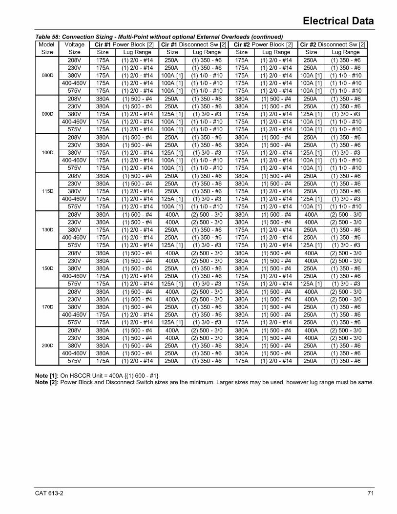
CAT 613-2 71
Electrical Data
Table 58: Connection Sizing - Multi-Point without optional External Overloads (continued)
Note [1]: On HSCCR Unit = 400A {(1) 600 - #1}Note [2]: Power Block and Disconnect Switch sizes are the minimum. Larger sizes may be used, however lug range must be same.
Model VoltageSize Size Size Lug Range Size Lug Range Size Lug Range Size Lug Range
208V 175A (1) 2/0 - #14 250A (1) 350 - #6 175A (1) 2/0 - #14 250A (1) 350 - #6230V 175A (1) 2/0 - #14 250A (1) 350 - #6 175A (1) 2/0 - #14 250A (1) 350 - #6380V 175A (1) 2/0 - #14 100A [1] (1) 1/0 - #10 175A (1) 2/0 - #14 100A [1] (1) 1/0 - #10
400-460V 175A (1) 2/0 - #14 100A [1] (1) 1/0 - #10 175A (1) 2/0 - #14 100A [1] (1) 1/0 - #10575V 175A (1) 2/0 - #14 100A [1] (1) 1/0 - #10 175A (1) 2/0 - #14 100A [1] (1) 1/0 - #10208V 380A (1) 500 - #4 250A (1) 350 - #6 380A (1) 500 - #4 250A (1) 350 - #6230V 380A (1) 500 - #4 250A (1) 350 - #6 380A (1) 500 - #4 250A (1) 350 - #6380V 175A (1) 2/0 - #14 125A [1] (1) 3/0 - #3 175A (1) 2/0 - #14 125A [1] (1) 3/0 - #3
400-460V 175A (1) 2/0 - #14 100A [1] (1) 1/0 - #10 175A (1) 2/0 - #14 100A [1] (1) 1/0 - #10575V 175A (1) 2/0 - #14 100A [1] (1) 1/0 - #10 175A (1) 2/0 - #14 100A [1] (1) 1/0 - #10208V 380A (1) 500 - #4 250A (1) 350 - #6 380A (1) 500 - #4 250A (1) 350 - #6230V 380A (1) 500 - #4 250A (1) 350 - #6 380A (1) 500 - #4 250A (1) 350 - #6380V 175A (1) 2/0 - #14 125A [1] (1) 3/0 - #3 175A (1) 2/0 - #14 125A [1] (1) 3/0 - #3
400-460V 175A (1) 2/0 - #14 100A [1] (1) 1/0 - #10 175A (1) 2/0 - #14 100A [1] (1) 1/0 - #10575V 175A (1) 2/0 - #14 100A [1] (1) 1/0 - #10 175A (1) 2/0 - #14 100A [1] (1) 1/0 - #10208V 380A (1) 500 - #4 250A (1) 350 - #6 380A (1) 500 - #4 250A (1) 350 - #6230V 380A (1) 500 - #4 250A (1) 350 - #6 380A (1) 500 - #4 250A (1) 350 - #6380V 175A (1) 2/0 - #14 250A (1) 350 - #6 175A (1) 2/0 - #14 250A (1) 350 - #6
400-460V 175A (1) 2/0 - #14 125A [1] (1) 3/0 - #3 175A (1) 2/0 - #14 125A [1] (1) 3/0 - #3575V 175A (1) 2/0 - #14 100A [1] (1) 1/0 - #10 175A (1) 2/0 - #14 100A [1] (1) 1/0 - #10208V 380A (1) 500 - #4 400A (2) 500 - 3/0 380A (1) 500 - #4 400A (2) 500 - 3/0230V 380A (1) 500 - #4 400A (2) 500 - 3/0 380A (1) 500 - #4 400A (2) 500 - 3/0380V 175A (1) 2/0 - #14 250A (1) 350 - #6 175A (1) 2/0 - #14 250A (1) 350 - #6
400-460V 175A (1) 2/0 - #14 250A (1) 350 - #6 175A (1) 2/0 - #14 250A (1) 350 - #6575V 175A (1) 2/0 - #14 125A [1] (1) 3/0 - #3 175A (1) 2/0 - #14 125A [1] (1) 3/0 - #3208V 380A (1) 500 - #4 400A (2) 500 - 3/0 380A (1) 500 - #4 400A (2) 500 - 3/0230V 380A (1) 500 - #4 400A (2) 500 - 3/0 380A (1) 500 - #4 400A (2) 500 - 3/0380V 380A (1) 500 - #4 250A (1) 350 - #6 380A (1) 500 - #4 250A (1) 350 - #6
400-460V 175A (1) 2/0 - #14 250A (1) 350 - #6 175A (1) 2/0 - #14 250A (1) 350 - #6575V 175A (1) 2/0 - #14 125A [1] (1) 3/0 - #3 175A (1) 2/0 - #14 125A [1] (1) 3/0 - #3208V 380A (1) 500 - #4 400A (2) 500 - 3/0 380A (1) 500 - #4 400A (2) 500 - 3/0230V 380A (1) 500 - #4 400A (2) 500 - 3/0 380A (1) 500 - #4 400A (2) 500 - 3/0380V 380A (1) 500 - #4 250A (1) 350 - #6 380A (1) 500 - #4 250A (1) 350 - #6
400-460V 175A (1) 2/0 - #14 250A (1) 350 - #6 380A (1) 500 - #4 250A (1) 350 - #6575V 175A (1) 2/0 - #14 125A [1] (1) 3/0 - #3 175A (1) 2/0 - #14 250A (1) 350 - #6208V 380A (1) 500 - #4 400A (2) 500 - 3/0 380A (1) 500 - #4 400A (2) 500 - 3/0230V 380A (1) 500 - #4 400A (2) 500 - 3/0 380A (1) 500 - #4 400A (2) 500 - 3/0380V 380A (1) 500 - #4 250A (1) 350 - #6 380A (1) 500 - #4 250A (1) 350 - #6
400-460V 380A (1) 500 - #4 250A (1) 350 - #6 380A (1) 500 - #4 250A (1) 350 - #6575V 175A (1) 2/0 - #14 250A (1) 350 - #6 175A (1) 2/0 - #14 250A (1) 350 - #6
080D
090D
100D
115D
130D
150D
170D
200D
Cir #2 Power Block [2] Cir #2 Disconnect Sw [2]Cir #1 Power Block [2] Cir #1 Disconnect Sw [2]
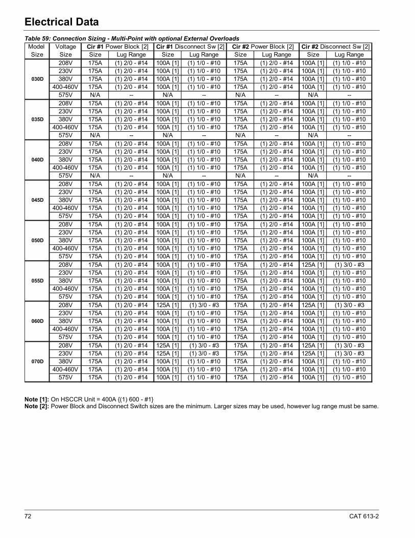
72 CAT 613-2
Electrical Data
Table 59: Connection Sizing - Multi-Point with optional External Overloads
Note [1]: On HSCCR Unit = 400A {(1) 600 - #1}Note [2]: Power Block and Disconnect Switch sizes are the minimum. Larger sizes may be used, however lug range must be same.
Model VoltageSize Size Size Lug Range Size Lug Range Size Lug Range Size Lug Range
208V 175A (1) 2/0 - #14 100A [1] (1) 1/0 - #10 175A (1) 2/0 - #14 100A [1] (1) 1/0 - #10230V 175A (1) 2/0 - #14 100A [1] (1) 1/0 - #10 175A (1) 2/0 - #14 100A [1] (1) 1/0 - #10380V 175A (1) 2/0 - #14 100A [1] (1) 1/0 - #10 175A (1) 2/0 - #14 100A [1] (1) 1/0 - #10
400-460V 175A (1) 2/0 - #14 100A [1] (1) 1/0 - #10 175A (1) 2/0 - #14 100A [1] (1) 1/0 - #10575V N/A -- N/A -- N/A -- N/A --208V 175A (1) 2/0 - #14 100A [1] (1) 1/0 - #10 175A (1) 2/0 - #14 100A [1] (1) 1/0 - #10230V 175A (1) 2/0 - #14 100A [1] (1) 1/0 - #10 175A (1) 2/0 - #14 100A [1] (1) 1/0 - #10380V 175A (1) 2/0 - #14 100A [1] (1) 1/0 - #10 175A (1) 2/0 - #14 100A [1] (1) 1/0 - #10
400-460V 175A (1) 2/0 - #14 100A [1] (1) 1/0 - #10 175A (1) 2/0 - #14 100A [1] (1) 1/0 - #10575V N/A -- N/A -- N/A -- N/A --208V 175A (1) 2/0 - #14 100A [1] (1) 1/0 - #10 175A (1) 2/0 - #14 100A [1] (1) 1/0 - #10230V 175A (1) 2/0 - #14 100A [1] (1) 1/0 - #10 175A (1) 2/0 - #14 100A [1] (1) 1/0 - #10380V 175A (1) 2/0 - #14 100A [1] (1) 1/0 - #10 175A (1) 2/0 - #14 100A [1] (1) 1/0 - #10
400-460V 175A (1) 2/0 - #14 100A [1] (1) 1/0 - #10 175A (1) 2/0 - #14 100A [1] (1) 1/0 - #10575V N/A -- N/A -- N/A -- N/A --208V 175A (1) 2/0 - #14 100A [1] (1) 1/0 - #10 175A (1) 2/0 - #14 100A [1] (1) 1/0 - #10230V 175A (1) 2/0 - #14 100A [1] (1) 1/0 - #10 175A (1) 2/0 - #14 100A [1] (1) 1/0 - #10380V 175A (1) 2/0 - #14 100A [1] (1) 1/0 - #10 175A (1) 2/0 - #14 100A [1] (1) 1/0 - #10
400-460V 175A (1) 2/0 - #14 100A [1] (1) 1/0 - #10 175A (1) 2/0 - #14 100A [1] (1) 1/0 - #10575V 175A (1) 2/0 - #14 100A [1] (1) 1/0 - #10 175A (1) 2/0 - #14 100A [1] (1) 1/0 - #10208V 175A (1) 2/0 - #14 100A [1] (1) 1/0 - #10 175A (1) 2/0 - #14 100A [1] (1) 1/0 - #10230V 175A (1) 2/0 - #14 100A [1] (1) 1/0 - #10 175A (1) 2/0 - #14 100A [1] (1) 1/0 - #10380V 175A (1) 2/0 - #14 100A [1] (1) 1/0 - #10 175A (1) 2/0 - #14 100A [1] (1) 1/0 - #10
400-460V 175A (1) 2/0 - #14 100A [1] (1) 1/0 - #10 175A (1) 2/0 - #14 100A [1] (1) 1/0 - #10575V 175A (1) 2/0 - #14 100A [1] (1) 1/0 - #10 175A (1) 2/0 - #14 100A [1] (1) 1/0 - #10208V 175A (1) 2/0 - #14 100A [1] (1) 1/0 - #10 175A (1) 2/0 - #14 125A [1] (1) 3/0 - #3230V 175A (1) 2/0 - #14 100A [1] (1) 1/0 - #10 175A (1) 2/0 - #14 100A [1] (1) 1/0 - #10380V 175A (1) 2/0 - #14 100A [1] (1) 1/0 - #10 175A (1) 2/0 - #14 100A [1] (1) 1/0 - #10
400-460V 175A (1) 2/0 - #14 100A [1] (1) 1/0 - #10 175A (1) 2/0 - #14 100A [1] (1) 1/0 - #10575V 175A (1) 2/0 - #14 100A [1] (1) 1/0 - #10 175A (1) 2/0 - #14 100A [1] (1) 1/0 - #10208V 175A (1) 2/0 - #14 125A [1] (1) 3/0 - #3 175A (1) 2/0 - #14 125A [1] (1) 3/0 - #3230V 175A (1) 2/0 - #14 100A [1] (1) 1/0 - #10 175A (1) 2/0 - #14 100A [1] (1) 1/0 - #10380V 175A (1) 2/0 - #14 100A [1] (1) 1/0 - #10 175A (1) 2/0 - #14 100A [1] (1) 1/0 - #10
400-460V 175A (1) 2/0 - #14 100A [1] (1) 1/0 - #10 175A (1) 2/0 - #14 100A [1] (1) 1/0 - #10575V 175A (1) 2/0 - #14 100A [1] (1) 1/0 - #10 175A (1) 2/0 - #14 100A [1] (1) 1/0 - #10208V 175A (1) 2/0 - #14 125A [1] (1) 3/0 - #3 175A (1) 2/0 - #14 125A [1] (1) 3/0 - #3230V 175A (1) 2/0 - #14 125A [1] (1) 3/0 - #3 175A (1) 2/0 - #14 125A [1] (1) 3/0 - #3380V 175A (1) 2/0 - #14 100A [1] (1) 1/0 - #10 175A (1) 2/0 - #14 100A [1] (1) 1/0 - #10
400-460V 175A (1) 2/0 - #14 100A [1] (1) 1/0 - #10 175A (1) 2/0 - #14 100A [1] (1) 1/0 - #10575V 175A (1) 2/0 - #14 100A [1] (1) 1/0 - #10 175A (1) 2/0 - #14 100A [1] (1) 1/0 - #10
035D
040D
045D
050D
055D
060D
070D
030D
Cir #1 Power Block [2] Cir #1 Disconnect Sw [2] Cir #2 Power Block [2] Cir #2 Disconnect Sw [2]
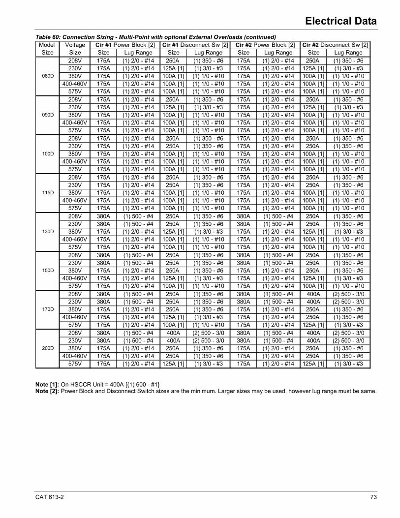
CAT 613-2 73
Electrical Data
Table 60: Connection Sizing - Multi-Point with optional External Overloads (continued)
Note [1]: On HSCCR Unit = 400A {(1) 600 - #1}Note [2]: Power Block and Disconnect Switch sizes are the minimum. Larger sizes may be used, however lug range must be same.
Model VoltageSize Size Size Lug Range Size Lug Range Size Lug Range Size Lug Range
208V 175A (1) 2/0 - #14 250A (1) 350 - #6 175A (1) 2/0 - #14 250A (1) 350 - #6230V 175A (1) 2/0 - #14 125A [1] (1) 3/0 - #3 175A (1) 2/0 - #14 125A [1] (1) 3/0 - #3380V 175A (1) 2/0 - #14 100A [1] (1) 1/0 - #10 175A (1) 2/0 - #14 100A [1] (1) 1/0 - #10
400-460V 175A (1) 2/0 - #14 100A [1] (1) 1/0 - #10 175A (1) 2/0 - #14 100A [1] (1) 1/0 - #10575V 175A (1) 2/0 - #14 100A [1] (1) 1/0 - #10 175A (1) 2/0 - #14 100A [1] (1) 1/0 - #10208V 175A (1) 2/0 - #14 250A (1) 350 - #6 175A (1) 2/0 - #14 250A (1) 350 - #6230V 175A (1) 2/0 - #14 125A [1] (1) 3/0 - #3 175A (1) 2/0 - #14 125A [1] (1) 3/0 - #3380V 175A (1) 2/0 - #14 100A [1] (1) 1/0 - #10 175A (1) 2/0 - #14 100A [1] (1) 1/0 - #10
400-460V 175A (1) 2/0 - #14 100A [1] (1) 1/0 - #10 175A (1) 2/0 - #14 100A [1] (1) 1/0 - #10575V 175A (1) 2/0 - #14 100A [1] (1) 1/0 - #10 175A (1) 2/0 - #14 100A [1] (1) 1/0 - #10208V 175A (1) 2/0 - #14 250A (1) 350 - #6 175A (1) 2/0 - #14 250A (1) 350 - #6230V 175A (1) 2/0 - #14 250A (1) 350 - #6 175A (1) 2/0 - #14 250A (1) 350 - #6380V 175A (1) 2/0 - #14 100A [1] (1) 1/0 - #10 175A (1) 2/0 - #14 100A [1] (1) 1/0 - #10
400-460V 175A (1) 2/0 - #14 100A [1] (1) 1/0 - #10 175A (1) 2/0 - #14 100A [1] (1) 1/0 - #10575V 175A (1) 2/0 - #14 100A [1] (1) 1/0 - #10 175A (1) 2/0 - #14 100A [1] (1) 1/0 - #10208V 175A (1) 2/0 - #14 250A (1) 350 - #6 175A (1) 2/0 - #14 250A (1) 350 - #6230V 175A (1) 2/0 - #14 250A (1) 350 - #6 175A (1) 2/0 - #14 250A (1) 350 - #6380V 175A (1) 2/0 - #14 100A [1] (1) 1/0 - #10 175A (1) 2/0 - #14 100A [1] (1) 1/0 - #10
400-460V 175A (1) 2/0 - #14 100A [1] (1) 1/0 - #10 175A (1) 2/0 - #14 100A [1] (1) 1/0 - #10575V 175A (1) 2/0 - #14 100A [1] (1) 1/0 - #10 175A (1) 2/0 - #14 100A [1] (1) 1/0 - #10208V 380A (1) 500 - #4 250A (1) 350 - #6 380A (1) 500 - #4 250A (1) 350 - #6230V 380A (1) 500 - #4 250A (1) 350 - #6 380A (1) 500 - #4 250A (1) 350 - #6380V 175A (1) 2/0 - #14 125A [1] (1) 3/0 - #3 175A (1) 2/0 - #14 125A [1] (1) 3/0 - #3
400-460V 175A (1) 2/0 - #14 100A [1] (1) 1/0 - #10 175A (1) 2/0 - #14 100A [1] (1) 1/0 - #10575V 175A (1) 2/0 - #14 100A [1] (1) 1/0 - #10 175A (1) 2/0 - #14 100A [1] (1) 1/0 - #10208V 380A (1) 500 - #4 250A (1) 350 - #6 380A (1) 500 - #4 250A (1) 350 - #6230V 380A (1) 500 - #4 250A (1) 350 - #6 380A (1) 500 - #4 250A (1) 350 - #6380V 175A (1) 2/0 - #14 250A (1) 350 - #6 175A (1) 2/0 - #14 250A (1) 350 - #6
400-460V 175A (1) 2/0 - #14 125A [1] (1) 3/0 - #3 175A (1) 2/0 - #14 125A [1] (1) 3/0 - #3575V 175A (1) 2/0 - #14 100A [1] (1) 1/0 - #10 175A (1) 2/0 - #14 100A [1] (1) 1/0 - #10208V 380A (1) 500 - #4 250A (1) 350 - #6 380A (1) 500 - #4 400A (2) 500 - 3/0230V 380A (1) 500 - #4 250A (1) 350 - #6 380A (1) 500 - #4 400A (2) 500 - 3/0380V 175A (1) 2/0 - #14 250A (1) 350 - #6 175A (1) 2/0 - #14 250A (1) 350 - #6
400-460V 175A (1) 2/0 - #14 125A [1] (1) 3/0 - #3 175A (1) 2/0 - #14 250A (1) 350 - #6575V 175A (1) 2/0 - #14 100A [1] (1) 1/0 - #10 175A (1) 2/0 - #14 125A [1] (1) 3/0 - #3208V 380A (1) 500 - #4 400A (2) 500 - 3/0 380A (1) 500 - #4 400A (2) 500 - 3/0230V 380A (1) 500 - #4 400A (2) 500 - 3/0 380A (1) 500 - #4 400A (2) 500 - 3/0380V 175A (1) 2/0 - #14 250A (1) 350 - #6 175A (1) 2/0 - #14 250A (1) 350 - #6
400-460V 175A (1) 2/0 - #14 250A (1) 350 - #6 175A (1) 2/0 - #14 250A (1) 350 - #6575V 175A (1) 2/0 - #14 125A [1] (1) 3/0 - #3 175A (1) 2/0 - #14 125A [1] (1) 3/0 - #3
090D
100D
115D
130D
150D
170D
200D
080D
Cir #1 Power Block [2] Cir #1 Disconnect Sw [2] Cir #2 Power Block [2] Cir #2 Disconnect Sw [2]
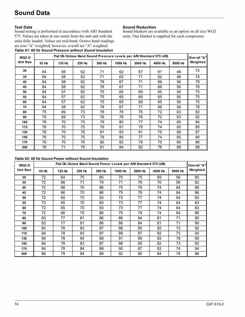
74 CAT 613-2
Sound DataSound Data
Test DataSound testing is performed in accordance with ARI Standard 575. Values are taken at one meter from the unit and with the units fully loaded. Values are mid-band. Octave band readings are non-”A” weighted; however, overall are "A" weighted.
Sound ReductionSound blankets are available as an option on all size WGZ units. One blanket is supplied for each compressor.
Table 61: 60 Hz Sound Pressure without Sound Insulation
Table 62: 60 Hz Sound Power without Sound Insulation
63 Hz 125 Hz 250 Hz 500 Hz 1000 Hz 2000 Hz 4000 Hz 8000 Hz
30 64 56 62 71 62 67 61 48 72
35 64 58 63 71 63 71 62 48 7440 64 58 62 78 67 71 66 56 7845 64 58 62 78 67 71 66 56 7850 64 57 62 75 65 69 65 56 7555 64 57 62 75 65 69 65 56 7560 64 57 62 75 65 69 65 56 7570 64 58 62 78 67 71 66 56 7880 75 69 73 78 78 76 72 63 8290 75 69 73 78 78 76 72 63 82
100 76 70 75 79 80 77 74 65 84115 76 70 75 79 81 79 74 65 85130 76 70 76 81 83 81 75 68 87150 76 70 75 79 80 77 74 65 84170 76 70 76 80 82 79 75 66 86200 78 71 76 81 84 82 76 68 88
WGZ-D Unit Size
Overall "A" Weighted
Flat Db Octave Band Sound Pressure Levels per ARI Standard 575 (dB)
63 Hz 125 Hz 250 Hz 500 Hz 1000 Hz 2000 Hz 4000 Hz 8000 Hz
30 72 64 70 80 70 75 69 56 8035 72 66 71 79 71 79 70 56 8240 72 66 70 86 75 79 74 64 8645 72 66 70 86 75 79 74 64 8650 72 65 70 83 73 77 74 64 8355 72 65 70 83 73 77 74 64 8360 72 65 70 83 73 77 74 64 8370 72 66 70 86 75 79 74 64 8680 83 77 81 86 86 84 81 71 9090 83 77 81 86 86 84 81 71 90100 84 78 83 87 88 85 82 73 92115 84 78 83 87 89 87 82 73 93130 84 78 84 89 91 89 83 76 95150 84 78 83 87 88 85 82 73 92170 84 78 84 88 90 87 83 74 94200 86 79 84 89 92 90 84 76 96
Overall "A" Weighted
WGZ-D Unit Size
Flat Db Octave Band Sound Power Levels per ARI Standard 575 (dB)
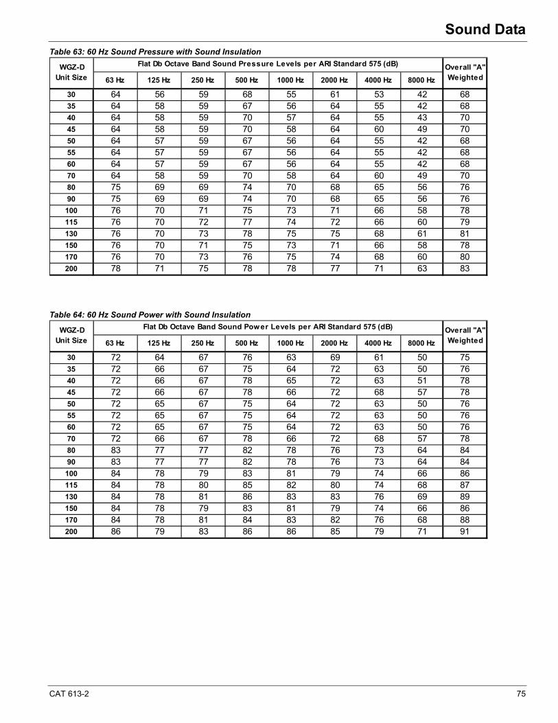
CAT 613-2 75
Sound Data
Table 63: 60 Hz Sound Pressure with Sound Insulation
Table 64: 60 Hz Sound Power with Sound Insulation
63 Hz 125 Hz 250 Hz 500 Hz 1000 Hz 2000 Hz 4000 Hz 8000 Hz
30 64 56 59 68 55 61 53 42 6835 64 58 59 67 56 64 55 42 6840 64 58 59 70 57 64 55 43 7045 64 58 59 70 58 64 60 49 7050 64 57 59 67 56 64 55 42 6855 64 57 59 67 56 64 55 42 6860 64 57 59 67 56 64 55 42 6870 64 58 59 70 58 64 60 49 7080 75 69 69 74 70 68 65 56 7690 75 69 69 74 70 68 65 56 76100 76 70 71 75 73 71 66 58 78115 76 70 72 77 74 72 66 60 79130 76 70 73 78 75 75 68 61 81150 76 70 71 75 73 71 66 58 78170 76 70 73 76 75 74 68 60 80200 78 71 75 78 78 77 71 63 83
WGZ-D Unit Size
Overall "A" Weighted
Flat Db Octave Band Sound Pressure Levels per ARI Standard 575 (dB)
63 Hz 125 Hz 250 Hz 500 Hz 1000 Hz 2000 Hz 4000 Hz 8000 Hz
30 72 64 67 76 63 69 61 50 7535 72 66 67 75 64 72 63 50 7640 72 66 67 78 65 72 63 51 7845 72 66 67 78 66 72 68 57 7850 72 65 67 75 64 72 63 50 7655 72 65 67 75 64 72 63 50 7660 72 65 67 75 64 72 63 50 7670 72 66 67 78 66 72 68 57 7880 83 77 77 82 78 76 73 64 8490 83 77 77 82 78 76 73 64 84100 84 78 79 83 81 79 74 66 86115 84 78 80 85 82 80 74 68 87130 84 78 81 86 83 83 76 69 89150 84 78 79 83 81 79 74 66 86170 84 78 81 84 83 82 76 68 88200 86 79 83 86 86 85 79 71 91
WGZ-D Unit Size
Overall "A" Weighted
Flat Db Octave Band Sound Power Levels per ARI Standard 575 (dB)
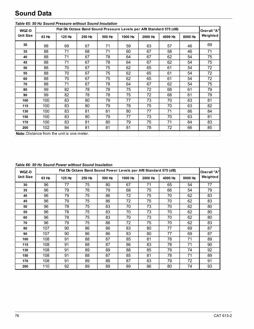
76 CAT 613-2
Sound Data
Table 65: 50 Hz Sound Pressure without Sound Insulation
Table 66: 50 Hz Sound Power without Sound Insulation
63 Hz 125 Hz 250 Hz 500 Hz 1000 Hz 2000 Hz 4000 Hz 8000 Hz
30 88 69 67 71 59 63 57 46 69
35 88 71 68 71 60 67 58 46 7140 88 71 67 78 64 67 62 54 7545 88 71 67 78 64 67 62 54 7550 88 70 67 75 62 65 61 54 7255 88 70 67 75 62 65 61 54 7260 88 70 67 75 62 65 61 54 7270 88 71 67 78 64 67 62 54 7580 99 82 78 78 75 72 68 61 7990 99 82 78 78 75 72 68 61 79100 100 83 80 79 77 73 70 63 81115 100 83 80 79 78 75 70 63 82130 100 83 81 81 80 77 71 66 84150 100 83 80 79 77 73 70 63 81170 100 83 81 80 79 75 71 64 83200 102 84 81 81 81 78 72 66 85
Note: Distance from the unit is one meter.
Overall "A" Weighted
WGZ-D Unit Size
Flat Db Octave Band Sound Pressure Levels per ARI Standard 575 (dB)
63 Hz 125 Hz 250 Hz 500 Hz 1000 Hz 2000 Hz 4000 Hz 8000 Hz
30 96 77 75 80 67 71 65 54 7735 96 79 76 79 68 75 66 54 7940 96 79 75 86 72 75 70 62 8345 96 79 75 86 72 75 70 62 8350 96 78 75 83 70 73 70 62 8055 96 78 75 83 70 73 70 62 8060 96 78 75 83 70 73 70 62 8070 96 79 75 86 72 75 70 62 8380 107 90 86 86 83 80 77 69 8790 107 90 86 86 83 80 77 69 87100 108 91 88 87 85 81 78 71 89115 108 91 88 87 86 83 78 71 90130 108 91 89 89 88 85 79 74 92150 108 91 88 87 85 81 78 71 89170 108 91 89 88 87 83 79 72 91200 110 92 89 89 89 86 80 74 93
WGZ-D Unit Size
Flat Db Octave Band Sound Power Levels per ARI Standard 575 (dB) Overall "A" Weighted

CAT 613-2 77
Sound Data
Table 67: 50 Hz Sound Pressure with Sound Insulation
Table 68: 50 Hz Sound Power with Sound Insulation
63 Hz 125 Hz 250 Hz 500 Hz 1000 Hz 2000 Hz 4000 Hz 8000 Hz
30 89 70 65 69 53 58 50 41 6635 89 72 65 68 54 61 52 41 6640 89 72 65 71 55 61 52 42 6845 89 72 65 71 56 61 57 48 6850 89 71 65 68 54 61 52 41 6655 89 71 65 68 54 61 52 41 6660 89 71 65 68 54 61 52 41 6670 89 72 65 71 56 61 57 48 6880 100 83 75 75 68 65 62 55 7490 100 83 75 75 68 65 62 55 74100 101 84 77 76 71 68 63 57 76115 101 84 78 78 72 69 63 59 77130 101 84 79 79 73 72 65 60 79150 101 84 77 76 71 68 63 57 76170 101 84 79 77 73 71 65 59 78200 103 85 81 79 76 74 68 62 81
Note: Distance from the unit is one meter.
Overall "A" Weighted
WGZ-D Unit Size
Flat Db Octave Band Sound Pressure Levels per ARI Standard 575 (dB)
63 Hz 125 Hz 250 Hz 500 Hz 1000 Hz 2000 Hz 4000 Hz 8000 Hz
30 97 78 73 77 61 66 58 49 7335 97 80 73 76 62 69 60 49 7440 97 80 73 79 63 69 60 50 7645 97 80 73 79 64 69 65 56 7650 97 79 73 76 62 69 60 49 7455 97 79 73 76 62 69 60 49 7460 97 79 73 76 62 69 60 49 7470 97 80 73 79 64 69 65 56 7680 108 91 83 83 76 73 70 63 8290 108 91 83 83 76 73 70 63 82100 109 92 85 84 79 76 71 65 84115 109 92 86 86 80 77 71 67 85130 109 92 87 87 81 80 73 68 87150 109 92 85 84 79 76 71 65 84170 109 92 87 85 81 79 73 67 86200 111 93 89 87 84 82 76 70 89
WGZ-D Unit Size
Flat Db Octave Band Sound Power Levels per ARI Standard 575 (dB) Overall "A" Weighted
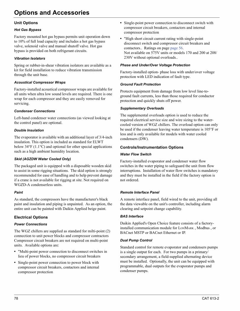
78 CAT 613-2
Options and AccessoriesOptions and Accessories
Unit Options
Hot Gas Bypass
Factory mounted hot gas bypass permits unit operation down to 10% of full load capacity and includes a hot gas bypass valve, solenoid valve and manual shutoff valve. Hot gas bypass is provided on both refrigerant circuits.
Vibration Isolators
Spring or rubber-in-shear vibration isolators are available as a kit for field installation to reduce vibration transmission through the unit base.
Acoustical Compressor Wraps
Factory-installed acoustical compressor wraps are available for all units when ultra low sound levels are required. There is one wrap for each compressor and they are easily removed for servicing.
Condenser Connections
Left-hand condenser water connections (as viewed looking at the control panel) are optional.
Double Insulation
The evaporator is available with an additional layer of 3/4-inch insulation. This option is included as standard for ELWT below 34°F (1.1°C) and optional for other special applications such as a high ambient humidity location.
Skid (AGZDW Water Cooled Only)
The packaged unit is equipped with a disposable wooden skid to assist in some rigging situations. The skid option is strongly recommended for ease of handling and to help prevent damage if a crane is not available for rigging at site. Not required on WGZD-A condenserless units.
Paint
As standard, the compressors have the manufacturer's black paint and insulation and piping is unpainted. As an option, the entire unit can be painted with Daikin Applied beige paint.
Electrical Options
Power Connections
The WGZ chillers are supplied as standard for milti-point (2) connection to unit power blocks and compressor contractors Compressor circuit breakers are not required on multi-point units. Available options are:
• "Multi-point power connection to disconnect switches in lieu of power blocks, no compressor circuit breakers
• Single-point power connection to power block with compressor circuit breakers, contactors and internal compressor protection
• Single-point power connection to disconnect switch with compressor circuit breakers, contactors and internal compressor protection
• "High short circuit current rating with single-point disconnect switch and compressor circuit breakers and contactors.. Ratings on page page 56.Not available on 575V units or models 170 and 200 at 208/230V without optional overloads..
Phase and Under/Over Voltage Protection
Factory-installed option- phase loss with under/over voltage protection with LED indication of fault type.
Ground Fault Protection
Protects equipment from damage from low level line-to-ground fault currents, less than those required for conductor protection and quickly shuts off power.
Supplementary Overloads
The supplemental overloads option is used to reduce the required electrical service size and wire sizing to the water-cooled version of WGZ chillers. The overload option can only be used if the condenser leaving water temperature is 105°F or less and is only available for models with water cooled condensers (DW).
Controls/Instrumentation Options
Water Flow Switch
Factory-installed evaporator and condenser water flow switches in the water piping to safeguard the unit from flow interruptions. Installation of water flow switches is mandatory and they must be installed in the field if the factory option is not ordered.
Remote Interface Panel
A remote interface panel, field wired to the unit, providing all the data viewable on the unit's controller, including alarm clearing and setpoint change capability.
BAS Interface
Daikin Applied's Open Choice feature consists of a factory-installed communication module for LONMARK , Modbus , or BACnet MSTP or BACnet Ethernet or IP.
Dual Pump Control
Standard control for remote evaporator and condensers pumps is a single output for each. For two pumps in a primary/secondary arrangement, a field-supplied alternating device must be installed. Optionally, the unit can be equipped with programmable, dual outputs for the evaporator pumps and condenser pumps.
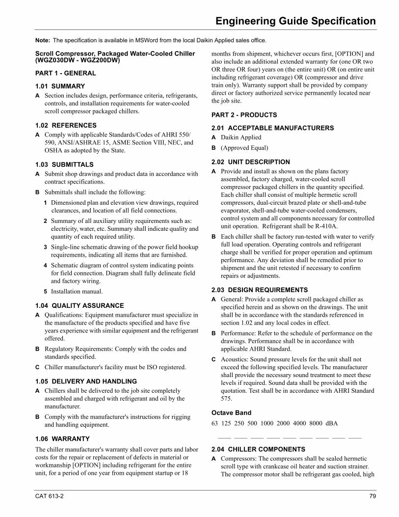
CAT 613-2 79
Engineering Guide SpecificationEngineering Guide Specification
Note: The specification is available in MSWord from the local Daikin Applied sales office.
Scroll Compressor, Packaged Water-Cooled Chiller (WGZ030DW - WGZ200DW)
PART 1 - GENERAL
1.01 SUMMARY
A Section includes design, performance criteria, refrigerants, controls, and installation requirements for water-cooled scroll compressor packaged chillers.
1.02 REFERENCES
A Comply with applicable Standards/Codes of AHRI 550/590, ANSI/ASHRAE 15, ASME Section VIII, NEC, and OSHA as adopted by the State.
1.03 SUBMITTALS
A Submit shop drawings and product data in accordance with contract specifications.
B Submittals shall include the following:
1 Dimensioned plan and elevation view drawings, required clearances, and location of all field connections.
2 Summary of all auxiliary utility requirements such as: electricity, water, etc. Summary shall indicate quality and quantity of each required utility.
3 Single-line schematic drawing of the power field hookup requirements, indicating all items that are furnished.
4 Schematic diagram of control system indicating points for field connection. Diagram shall fully delineate field and factory wiring.
5 Installation manual.
1.04 QUALITY ASSURANCE
A Qualifications: Equipment manufacturer must specialize in the manufacture of the products specified and have five years experience with similar equipment and the refrigerant offered.
B Regulatory Requirements: Comply with the codes and standards specified.
C Chiller manufacturer's facility must be ISO registered.
1.05 DELIVERY AND HANDLING
A Chillers shall be delivered to the job site completely assembled and charged with refrigerant and oil by the manufacturer.
B Comply with the manufacturer's instructions for rigging and handling equipment.
1.06 WARRANTY
The chiller manufacturer's warranty shall cover parts and labor costs for the repair or replacement of defects in material or workmanship [OPTION] including refrigerant for the entire unit, for a period of one year from equipment startup or 18
months from shipment, whichever occurs first, [OPTION] and also include an additional extended warranty for (one OR two OR three OR four) years on (the entire unit) OR (on entire unit including refrigerant coverage) OR (compressor and drive train only). Warranty support shall be provided by company direct or factory authorized service permanently located near the job site.
PART 2 - PRODUCTS
2.01 ACCEPTABLE MANUFACTURERS
A Daikin Applied
B (Approved Equal)
2.02 UNIT DESCRIPTION
A Provide and install as shown on the plans factory assembled, factory charged, water-cooled scroll compressor packaged chillers in the quantity specified. Each chiller shall consist of multiple hermetic scroll compressors, dual-circuit brazed plate or shell-and-tube evaporator, shell-and-tube water-cooled condensers, control system and all components necessary for controlled unit operation. Refrigerant shall be R-410A.
B Each chiller shall be factory run-tested with water to verify full load operation. Operating controls and refrigerant charge shall be verified for proper operation and optimum performance. Any deviation shall be remedied prior to shipment and the unit retested if necessary to confirm repairs or adjustments.
2.03 DESIGN REQUIREMENTS
A General: Provide a complete scroll packaged chiller as specified herein and as shown on the drawings. The unit shall be in accordance with the standards referenced in section 1.02 and any local codes in effect.
B Performance: Refer to the schedule of performance on the drawings. Performance shall be in accordance with applicable AHRI Standard.
C Acoustics: Sound pressure levels for the unit shall not exceed the following specified levels. The manufacturer shall provide the necessary sound treatment to meet these levels if required. Sound data shall be provided with the quotation. Test shall be in accordance with AHRI Standard 575.
Octave Band
63 125 250 500 1000 2000 4000 8000 dBA
____ ____ ____ ____ ____ ____ ____ ____ ____
2.04 CHILLER COMPONENTS
A Compressors: The compressors shall be sealed hermetic scroll type with crankcase oil heater and suction strainer. The compressor motor shall be refrigerant gas cooled, high
80 CAT 613-2
Engineering Guide Specification
torque, hermetic induction type, two-pole, with inherent thermal protection on all three phases and shall be mounted on RIS vibration isolator pads.[OPTION] The compressors shall be covered with factory-installed acoustical sound reduction blankets.
B Evaporator: On units 30 tons to 130 tons, the evaporator shall be direct expansion type with stainless steel brazed plates. It shall be insulated with ¾ inch (19mm), 0.28 k value, closed cell polyurethane insulation and have 653 psi (4500 kPa) water side working pressure. [OPTION] The evaporator shall have an additional layer of ¾-inch insulationOn units from 150 to 200 tons, the evaporator shall be shell-and-tube construction, insulated with 3/4 inch (19mm) closed cell polyurethane insulation, and with 150 psi (1033kPa) water-side working pressure.[OPTION] The evaporator shall have an additional layer of ¾-inch insulation
C Condenser: Horizontal shell and finned tube type with steel shell and integral finned copper tubes rolled into steel tube sheets. The chiller shall be equipped with intermediate tube supports. Construct condenser in accordance with the requirements of ASME Section VIII Unfired Pressure Vessel Code and ANSI B9.1 Safety Code. It shall be designed for 232 psi (1599 kPa) water side working pressure and 450 psig (3104 kPa) refrigerant side pressure and be provided with ASME, ANSI B9.1 pressure relief valves.
D Refrigerant Circuit: Each refrigerant circuit shall include a liquid line shutoff valve, replaceable core or sealed filter-drier, sight glass with moisture indicator, liquid line solenoid valve, thermal expansion valve, and insulated suction line.[OPTION] The unit shall include hot gas bypass on all cir-cuits.
E Control/Power Panel: The control panel shall contain a microprocessor controller providing operating and equipment protection controls plus motor starting equipment, factory wired, operationally tested, and ready for operation. Standard components shall include a control transformer with primary and secondary fusing, microprocessor transformers with integral fusing and switches for each circuit pumpdown and unit control power. Power connection shall be multi-point (2) to power block. The control panel shall have a hinged tool-locked door.[OPTION]Multi-point power connection to disconnect switches[OPTION]Single point power connection to a power block with compressor circuit breakers[OPTION]Single point power connection to a disconnect switch with compressor circuit breakers[OPTION]High short circuit current rating (HSCCR) single point power connection to a disconnect switch with com-pressor circuit breakers
The control system shall stage the compressors based on the leaving water temperature. Equipment protection devices controlled by the microprocessor include motor protection, high pressure, loss of refrigerant, loss of water flow, freeze protection, and low refrigerant pressure. Con-trols shall include auto/stop switch, chilled water setpoint adjustment, anti-recycle timer, and digital display with water temperature and setpoint, operating temperatures and pressures, and diagnostic messages. The following features and functions shall be included:
1 The LCD-type display shall have a minimum of 20 characters with all messages in English. Coded messages are not acceptable.
2 Critical parameters shall have their own section of control and shall be password protected.
3 Resetting chilled water temperature by a remote 4-20mA DC signal.
4 A soft load function to prevent the system from operating at full load during the chilled water pulldown period.
5 An electronic time clock to allow programming of a yearly schedule accommodating weekends and holidays.
6 Auto restart after a power failure, not requiring external battery backup or auxiliary power for maintaining program memory.
7 Shutdowns shall be date and time stamped with system temperatures and pressures recorded. A minimum of six previous occurrences shall be kept in a revolving memory.
8 Start-to-start and stop-to-start timers to provide minimum compressor off-time with maximum motor protection.
9 Capability of communication with a PC or remote monitoring through a twisted pair RS-232 interface.
10 Demand limiting via a 4-20ma remote signal
11 Lead/lag manually or automatically by compressor number of starts.
12 Continuous diagnostic checks of unit to provide a pre-alarm signal in advance of a shutdown allowing time for remedial action to be taken.
13 Demand limiting via remote 4-20ma signal
14 The controller shall contain the following features as a minimum:
a Equipment Protection -The unit shall be protected in two ways: (1) by alarms that shut the unit down and require manual reset to restore unit operation and (2) by limit alarms that reduce unit operation in response to some out-of-limit condition. Shut down alarms shall activate an alarm signal.
b Shutdown Alarms
• No evaporator water flow
CAT 613-2 81
Engineering Guide Specification
• Low evaporator pressure
• High condenser pressure
• Motor protection system
• Phase voltage protection (Optional)
• Outside ambient temperature
• Evaporator freeze protection
• Sensor failures
c Limit Alarms
• Condenser pressure stage down, unloads unit at high discharge pressures
• Low ambient lockout, shuts off unit at low ambient temperatures
• Low evaporator pressure hold, holds stage #1 until pressure rises
• Low evaporator pressure unload, shuts off one com-pressor
d Unit Enable Selection
• Enables unit operation from local keypad, digital input, or BAS
e Unit Mode Selection
• Selects cooling, ice, glycol, or test operation mode
f Analog Inputs
• Reset of leaving water temperature, 4-20 mA
g Digital Inputs
• Unit off switch
• Remote start/stop
• Flow switch
• Ice mode, converts operation and setpoints for ice production
• Motor protection
h Digital Outputs
• Shutdown alarm; field wired, activates on an alarm condition, off when alarm is cleared
• Evaporator pump; field wired, starts pump when unit is set to start
15 Optional Building Automation System (BAS) Interface
a The unit shall be equipped with an optional factory-installed BAS communication module. Factory mounted DDC controller(s) shall support operation on a BACnet®, Modbus® or LONMARK® network via one of the data link / physical layers listed below
as specified by the successful Building Automation System (BAS) supplier.
• BACnet MS/TP master (Clause 9)
• BACnet IP, (Annex J)
• BACnet ISO 8802-3, (Ethernet)
• LONMARKS FTT-10A. The unit controller shall be LONMARKS® certified.
The information communicated between the BAS and the factory mounted unit controllers shall include the reading and writing of data to allow unit monitoring, control and alarm notification as specified in the unit sequence of oper-ation and the unit points list. For chillers communicating over a LONMARK network, the corresponding LONMARK eXternal Interface File (XIF) shall be provided with the chiller submittal data.All communication from the chiller unit controller as speci-fied in the points list shall be via standard BACnet objects. Proprietary BACnet objects shall not be allowed. BACnet communications shall conform to the BACnet protocol (ANSI/ASHRAE135-2001). A BACnet Protocol Imple-mentation Conformance Statement (PICS) shall be pro-vided along with the unit submittal.
The following options are to be included:[OPTION] The unit shall be shipped with R-I-S vibration isolators for field installation per plans.[OPTION] The unit shall be shipped with spring vibration isolators for field installation per plans.[OPTION] Shipping skid
PART 3 - EXECUTION
3.01 INSTALLATION
A Install in strict accordance with manufacturer's requirements, shop drawings, and Contract Documents.
B Adjust and level chiller in alignment on supports.
C Coordinate electrical installation with electrical contractor.
D Coordinate controls with control contractor.
E Provide all appurtenances required to ensure a fully operational and functional chiller.
3.02 START-UP
A Ensure proper charge of refrigerant and oil.
B Provide testing, and starting of machine, and instruct the Owner in its proper operation and maintenance.
82 CAT 613-2
Engineering Guide Specification
Scroll Compressor Chiller, Less W-C Condenser WGZ 030DA - WGZ 200DA
PART 1 - GENERAL
1.01 SUMMARY
A Section includes design, performance criteria, refrigerants, controls, and installation requirements for water-cooled scroll compressor packaged chillers.
1.02 REFERENCES
A Comply with applicable Standards/Codes of ANSI/ASHRAE 15, NEC, and OSHA as adopted by the State.
B Equipment shall meet efficiency standards of ASHRAE Standard 90.1.
1.03 SUBMITTALS
A Submit shop drawings and product data in accordance with contract specifications.
B Submittals shall include the following:
1 Dimensioned plan and elevation view drawings, required clearances, and location of all field connections.
2 Summary of all auxiliary utility requirements such as: electricity, water, etc. Summary shall indicate quality and quantity of each required utility.
3 Single-line schematic drawing of the power field hookup requirements, indicating all items that are furnished.
4 Schematic diagram of control system indicating points for field connection. Diagram shall fully delineate field and factory wiring.
5 Installation manual.
1.04 QUALITY ASSURANCE
A Qualifications: Equipment manufacturer must specialize in the manufacture of the products specified and have five years experience with similar equipment and the refrigerant offered.
B Regulatory Requirements: Comply with the codes and standards specified.
C Chiller manufacturer must be ISO registered.
1.05 DELIVERY AND HANDLING
A Chillers shall be delivered to the job site completely assembled and ready for connection to a remote condenser. It shall be shipped a holding charge of nitrogen which shall be removed prior to charging with R-410A.
B Comply with the manufacturer's instructions for rigging and handling equipment.
1.04 WARRANTY
The equipment manufacturer's warranty shall be for a period of one year from date of equipment start-up but not more than 18
months from shipment. The warranty shall provide for repair or replacement due to failures caused by defective material and workmanship within the above period, excluding refrigerant.
PART 2--PRODUCTS
2.01 ACCEPTABLE MANUFACTURERS
A Daikin Applied
B (Approved Equal)
2.02 UNIT DESCRIPTION
A Provide and install as shown on the plans, factory assembled, (remote condenser furnished by others), scroll compressor packaged chiller(s) in the quantity specified. Each chiller shall consist of multiple hermetic scroll compressors, dual-circuit direct expansion evaporator, control system and, when completely installed with the remote condenser, constitute all components necessary for controlled unit operation. Refrigerant shall be R-410A. The condenser interconnecting piping shall be furnished and installed by the contractor.
2.03 DESIGN REQUIREMENTS
A General: Provide a complete scroll compressor packaged chiller as specified herein and as shown on the drawings. The unit shall be in accordance with the standards referenced in section 1.02 and any local codes in effect.
B Performance: Refer to the schedule of performance on the drawings. Performance shall be in accordance with applicable AHRI Standard.
C Acoustics: Sound pressure levels for the unit shall not exceed the following specified levels. The manufacturer shall provide the necessary sound treatment to meet these levels if required. Sound data shall be provided with the quotation. Test shall be in accordance with AHRI Standard 575.
Octave Band
63 125 250 500 1000 2000 4000 8000 dBA
____ ____ ____ ____ ____ ____ ____ ____ ____
2.04 CHILLER COMPONENTS
A Compressors: The compressors shall be sealed hermetic scroll type with crankcase oil heater and suction strainer. The compressor motor shall be refrigerant gas cooled, high torque, hermetic induction type, two-pole, with inherent thermal protection on all three phases and shall be mounted on RIS vibration isolator pads.
[OPTION] The compressors shall be covered with factory-installed sound reduction acoustical blankets.
B Evaporator: On units 30 tons to 130 tons, the evaporator shall be direct expansion type with stainless steel plates brazed together. It shall be insulated with 3/4 inch (19mm),
CAT 613-2 83
Engineering Guide Specification
0.28 k value, closed cell polyurethane insulation. It shall be designed for 653 psi (4500 kPa) water side working pressure.
[OPTION] The evaporator shall have an additional layer of ¾-inch insulation
On units from 150 to 200 tons, the evaporator shall be shell-and-tube construction, designed for 150 psig (1033 kPa) water side pressure, and insulated with 3/4 inch (19mm) closed cell polyurethane insulation..
[OPTION] The evaporator shall have an additional layer of ¾-inch insulation
C Condenser: contractor supplied and installed to match the chiller performance at specified ambient conditions.
D Refrigerant Circuit: Each refrigerant circuit shall include a liquid line shutoff valve, replaceable core or sealed filter-drier, sight glass with moisture indicator, liquid line solenoid valve (no exceptions), thermal expansion valve, and insulated suction line.
[OPTION] The unit shall include hot gas bypass on all circuits.
E Control Panel: The control panel shall contain a microprocessor controller providing operating and equipment protection controls plus motor starting equipment, factory wired, operationally tested, and ready for operation. Standard components shall include a control transformer with primary and secondary fusing, microprocessor transformers with integral fusing and switches for each circuit pumpdown and unit control power. Power connection shall be multi-point (2) to power block. The control panel shall have a hinged tool-locked door.
[OPTION]Multi-point power connection to disconnect switches
[OPTION]Single point power connection to a power block with compressor circuit breakers
[OPTION]Single point power connection to a disconnect switch with compressor circuit breakers
[OPTION]High short circuit current rating (HSCCR) single point power connection to a disconnect switch with compressor circuit breakers
The control system shall stage the compressors based on the leaving water temperature. Equipment protection devices controlled by the microprocessor include motor protection, high pressure, loss of refrigerant, loss of water flow, freeze protection, and low refrigerant pressure. Controls shall include auto/stop switch, chilled water setpoint adjustment, anti-recycle timer, and digital display with water temperature and setpoint, operating temperatures and pressures, and diagnostic messages. The following features and functions shall be included:
1 The LCD type display shall have a minimum of 20 characters with all messages in English. Coded messages are not acceptable.
2 Critical parameters shall have their own section of control and shall be password protected.
3 Resetting chilled water temperature by a remote 4-20mA DC signal.
4 A soft load function to prevent the system from operating at full load during the chilled water pulldown period.
5 An electronic time clock to allow programming of a yearly schedule accommodating weekends and holidays.
6 Auto restart after a power failure, not requiring external battery back-up or auxiliary power for maintaining program memory.
7 Shutdowns shall be date and time stamped with system temperatures and pressures recorded. A minimum of six previous occurrences shall be kept in a revolving memory.
8 Start-to-start and stop-to-start timers t.
9 Capability of communication with a PC or remote monitoring through a twisted pair RS-232 interface.
10 Lead/lag by manually or automatically by compressor number of starts.
11 Continuous diagnostic checks of unit operation to provide a pre-alarm signal in advance of a shutdown allowing time for remedial action to be taken.
12 Contacts for control of up to 8 condenser fans
F An advanced DDC microprocessor unit controller with a 4-line by 20-character liquid crystal display provides the operating and protection functions.. The controller shall take pre-emptive limiting action in case of high discharge pressure or low evaporator pressure.
The controller shall contain the following features as a minimum:
Equipment Protection
The unit shall be protected in two ways: (1) by alarms that shut the unit down and require manual reset to restore unit operation and (2) by limit alarms that reduce unit operation in response to some out-of-limit condition. Shut down alarms shall activate an alarm signal.
Shutdown Alarms
• No evaporator water flow
• Low evaporator pressure
• High condenser pressure
• Motor protection system
• Phase voltage protection (Optional)
• Outside ambient temperature
84 CAT 613-2
Engineering Guide Specification
• Evaporator freeze protection
• Sensor failures
Limit Alarms
• Condenser pressure stage down, unloads unit at high discharge pressures
• Low ambient lockout, shuts off unit at low ambient temperatures
• Low evaporator pressure hold, holds stage #1 until pressure rises
• Low evaporator pressure unload, shuts off one compressor
Unit Enable Selection
• Enables unit operation from local keypad, digital input, or BAS
Unit Mode Selection
• Selects cooling, ice, glycol, or test operation mode
Analog Inputs
• Reset of leaving water temperature, 4-20 mA
Digital Inputs
• Unit off switch
• Remote start/stop
• Flow switch
• Ice mode, converts operation and setpoints for ice production
• Motor protection
Digital Outputs
• Shutdown alarm; field wired, activates on an alarm condition, off when alarm is cleared
• Evaporator pump; field wired, starts pump when unit is set to start
Condenser Fan Control
The unit controller shall be able to provide control of the remote condenser fans. The controller shall sequence condenser fans based on compressor discharge pressure.
Building Automation System (BAS) Interface
The unit shall be equipped with an optional factory-installed BAS communication module
Factory mounted DDC controller(s) shall support operation on a BACnet®, Modbus® or LONMARKS ® network via one of the data link / physical layers listed below as specified by the successful Building Automation System (BAS) supplier.
"BACnet MS/TP master (Clause 9)
"BACnet IP, (Annex J)
"BACnet ISO 8802-3, (Ethernet)
"LONMARKS FTT-10A. The unit controller shall be LONMARKS ® certified.
The information communicated between the BAS and the factory mounted unit controllers shall include the reading and writing of data to allow unit monitoring, control and alarm notification as specified in the unit sequence of operation and the unit points list.
For chillers communicating over a LONMARKS network, the corresponding LONMARKS eXternal Interface File (XIF) shall be provided with the chiller submittal data.
All communication from the chiller unit controller as specified in the points list shall be via standard BACnet objects. Proprietary BACnet objects shall not be allowed. BACnet communications shall conform to the BACnet protocol (ANSI/ASHRAE135-2001). A BACnet Protocol Implementation Conformance Statement (PICS) shall be provided along with the unit submittal.
[OPTION] Supplemental overloads reduce the required electrical service size and wire sizing
G G. The following options are to be included:
"[OPTION] The unit shall be shipped with R-I-S vibration isolators for field installation per plans.
"[OPTION] The unit shall be shipped with spring vibration isolators for field installation per plans.
"[OPTION]The unit shall be shipped on a shipping skid.
PART 3 - EXECUTION
3.01 INSTALLATION
A Install chiller and remote condenser with interconnecting piping and wiring in strict accordance with manufacturer's requirements, shop drawings, and Contract Documents. Chiller manufacturer must approve the refrigerant piping design.
B Adjust and level chiller in alignment on supports.
C Coordinate electrical installation with electrical contractor.
D Coordinate controls with control contractor.
E Install, pressure test, and evacuate field refrigerant piping.
F Provide all appurtenances required to insure a fully operational and functional chiller.
G Purge chiller unit and charge system with refrigerant and oil.
3.02 START-UP
A Ensure proper charge of refrigerant and oil.
B Provide testing, and starting of machine, and instruct the Owner in its proper operation and maintenance.


© 2014 Daikin Applied • www.DaikinApplied.com • 800-432-1342 (6/14)
Daikin Applied Training and Development
Now that you have made an investment in modern, efficient Daikin Applied equipment, its care should be a high priority. For training information on all Daikin Applied HVAC products, visit us at www.DaikinApplied.com and click on Training, or call 540-248-9646 to speak to the Training Department.
Warranty
All Daikin Applied equipment is sold pursuant to its standard terms and conditions of sale, including Limited Product Warranty. Consult your local Daikin Applied representative for warranty details. To find your local Daikin Applied representative, go to www.DaikinApplied.com.
Aftermarket Services
To find your local parts office, visit www.DaikinApplied.com or call 800-37PARTS (800-377-2787).To find your local service office, visit www.DaikinApplied.com or call 800-432-1342.
This document contains the most current product information as of this printing. For the most up-to-date product information, please go to www.DaikinApplied.com.
![PACKAGEHEATPUMPSFEATURING INDUSTRYSTANDARDR-410A … · 2019. 4. 11. · []indicatesmetricconversion installationinstructions packageheatpumpsfeaturing industrystandardr-410a refrigerant](https://static.fdocuments.us/doc/165x107/5ff73f17096e4b21c6037881/packageheatpumpsfeaturing-industrystandardr-410a-2019-4-11-indicatesmetricconversion.jpg)


![PACKAGEHEATPUMPSFEATURING INDUSTRYSTANDARDR-410A … · 2020. 3. 17. · []indicatesmetricconversion installationinstructions packageheatpumpsfeaturing industrystandardr-410a refrigerant](https://static.fdocuments.us/doc/165x107/5ff73ec723717515a65c591b/packageheatpumpsfeaturing-industrystandardr-410a-2020-3-17-indicatesmetricconversion.jpg)


