MODEL-TO-MODEL TRANSFORMATION APPROACH FOR SYSTEMATIC INTEGRATION … · model-to-model...
132
MODEL-TO-MODEL TRANSFORMATION APPROACH FOR SYSTEMATIC INTEGRATION OF SECURITY ASPECTS INTO UML 2.0 DESIGN MODELS Mariam Nouh A THESIS IN The Department of Concordia Institute for Information Systems Engineering Presented in Partial Fulfillment of the Requirements For the Degree of Master of Applied Science in Information System Security Concordia University Montréal, Québec, Canada July 2010 © Mariam Nouh, 2010
Transcript of MODEL-TO-MODEL TRANSFORMATION APPROACH FOR SYSTEMATIC INTEGRATION … · model-to-model...

MODEL-TO-MODEL TRANSFORMATION APPROACH FOR
SYSTEMATIC INTEGRATION OF SECURITY ASPECTS INTO
UML 2.0 DESIGN MODELS
Mariam Nouh
A THESIS
IN
The Department
of
Concordia Institute for Information Systems Engineering
Presented in Partial Fulfillment of the RequirementsFor the Degree of Master of Applied Science in Information System
SecurityConcordia University
Montréal, Québec, Canada
July 2010
© Mariam Nouh, 2010

?F? Library and ArchivesCanada
Published HeritageBranch
395 Wellington StreetOttawaONK1A0N4Canada
Bibliothèque etArchives Canada
Direction duPatrimoine de l'édition
395, rue WellingtonOttawaONK1A0N4Canada
Your file Votre référenceISBN: 978-0-494-71 101-9Our file Notre référenceISBN: 978-0-494-71 101-9
NOTICE: AVIS:
The author has granted a non-exclusive license allowing Library andArchives Canada to reproduce,publish, archive, preserve, conserve,communicate to the public bytelecommunication or on the Internet,loan, distribute and sell thesesworldwide, for commercial or non-commercial purposes, in microform,paper, electronic and/or any otherformats.
L'auteur a accordé une licence non exclusivepermettant à la Bibliothèque et ArchivesCanada de reproduire, publier, archiver,sauvegarder, conserver, transmettre au publicpar télécommunication ou par l'Internet, prêter,distribuer et vendre des thèses partout dans lemonde, à des fins commerciales ou autres, sursupport microforme, papier, électronique et/ouautres formats.
The author retains copyrightownership and moral rights in thisthesis. Neither the thesis norsubstantial extracts from it may beprinted or otherwise reproducedwithout the author's permission.
L'auteur conserve la propriété du droit d'auteuret des droits moraux qui protège cette thèse. Nila thèse ni des extraits substantiels de celle-cine doivent être imprimés ou autrementreproduits sans son autorisation.
In compliance with the CanadianPrivacy Act some supporting formsmay have been removed from thisthesis.
Conformément à la loi canadienne sur laprotection de la vie privée, quelquesformulaires secondaires ont été enlevés decette thèse.
While these forms may be includedin the document page count, theirremoval does not represent any lossof content from the thesis.
Bien que ces formulaires aient inclus dansla pagination, il n'y aura aucun contenumanquant.
1+1
Canada

Abstract
Model-to-Model Transformation Approach for Systematic Integration of SecurityAspects into UML 2.0 Design Models
Mariam Nouh
Security is a challenging task in software engineering. Traditionally, security concernsare considered as an afterthought to the development process and thus are fittedinto pre-existing software without the consideration of whether this would jeopardizethe main functionality of the software or even produce additional vulnerabilities.Enforcing security policies should be taken care of during early phases of the softwaredevelopment life cycle in order to decrease the development costs and reduce themaintenance time. In addition to cost saving, this way of development will producemore reliable software since security related concepts will be considered in each step ofthe design. Similarly, the implications of inserting such mechanisms into the existingsystem's requirements will be considered as well.
Since security is a crosscutting concern that pervades the entire software, inte-grating security solutions at the software design level may result in the scatteringand tangling of security features throughout the entire design. Additionally, tra-ditional hardening approaches are tedious and error-prone as they involve manualmodifications. In this context, the need for a systematic way to integrate securityconcerns into the process of developing software becomes crucial. In this thesis, wedefine an aspect-oriented modeling approach for specifying and integrating securityconcerns into UML design models. The proposed approach makes use of the expertiseof the software security specialist by providing him with the means to specify genericUML aspects that are going to be incorporated "weaved" into the developers' models.Model transformation mechanisms are instrumented in order to have an efficient anda fully automatic weaving process.
m

Acknowledgments
It is my pleasure to thank all those who made this thesis possible.
First and for most I thank God for granting me the chance to pursue my studiesand for guiding me all through the way.
I owe my deepest gratitude to my supervisor and mentor, Dr. Mourad Debbabi,for introducing me to the field of academic research and providing me with the op-portunity to conduct this exciting research. His constant guidance, support, andencouragement played the major role in making this research possible.
I would also like to thank all my colleagues in the Model-Based Engineering of SecureSoftware and Systems (M0BS2) project for their participation in this research and formaking it a joyful experience. I would like to extend a special gratitude to DjedjigaMouheb, with whom I closely collaborated in my research. She was a great supportduring my first months in the lab, she provided invaluable assistance and above allshe was and is a great friend.
I owe my family a special thanks for the moral support they gave me. My heart-felt thanks go to my parents for their constant support all through the way whichwas invaluable.
I dedicate this thesis to them, and to my lovely niece, and new born nephew..You all are my muse.
IV

Contents
List of Figures viii
List of Tables ?
1 Introduction 1
1.1 Problem Statement 3
1.2 Objectives 41.3 Contributions 5
1.4 Assumptions and Limitations 51.5 Thesis Structure 6
2 Background 82.1 Software Security 9
2.1.1 Confidentiality 92.1.2 Integrity 92.1.3 Authentication 9
2.1.4 Availability 102.1.5 Non-Repudiation 10
2.2 UML: The Unified Modeling Language 102.2.1 Terms and Definitions 102.2.2 UML Structure 12
2.2.3 UML Views and Concepts . . . 132.2.4 Extensibility Mechanisms in UML 152.2.5 OCL: Object Constraint Language 16
2.3 Aspect-Oriented Paradigm 162.3.1 Aspects 182.3.2 Join Points and Pointcuts 18
V

2.3.3 Advices 18
2.3.4 Weaving 192.4 MDA: Model Driven Architecture 19
2.4.1 MDA Layers 202.4.2 MDA Benefits 212.4.3 MDA Transformations 23
2.4.4 QVT: The Standard Language 25
3 Security Hardening of Software Design Models 273.1 Security Design Patterns 283.2 Mechanism-Directed Meta-Languages 303.3 Aspect-Oriented Modeling 323.4 Summary 36
4 Model Transformation and Model Weaving 384.1 Applications of Model Transformations 414.2 Model Transformation Languages 43
4.2.1 Atlas Transformation Language (ATL) 444.2.2 Open Architecture Ware (oAW) 444.2.3 IBM Model Transformation Framework (MTF) 454.2.4 Kermeta 45
4.2.5 QVT Operational (QVTO) 464.2.6 Comparative Study 46
4.3 Related Work on Model Weaving 494.4 Summary 53
5 Security Aspect Specification 545.1 Approach Overview 555.2 A UML Profile for Aspect-Oriented Modeling 565.3 Aspect Adaptations 57
5.3.1 Structural Adaptations 585.3.2 Behavioral Adaptations 59
5.4 Aspect Adaptation Rules 595.4.1 Adding a New Element 605.4.2 Removing an Element 61
5.5 Pointcuts 62
vi

5.5.1 Pointcut Expression Language 635.6 Summary 64
6 Weaving Aspects into UML Design Models 656.1 Aspects Specialization 676.2 Pointcut Parsing and OCL Generation 686.3 Aspect Weaving Process 69
6.3.1 Weaving Engine General Architecture 696.3.2 Transformation Definitions 726.3.3 Transformation Rules 85
6.4 Summary 92
7 Aspects Weaving Plug-in 947.1 M0BS2 Framework 95
7.2 Aspects Weaving Plug-in 967.3 Case Study: Service Provider Application 98
7.3.1 Role-Based Access Control (RBAC) Aspect 1007.3.2 Input Validation Aspect 104
7.4 Summary 106
8 Conclusion 107
Bibliography 109
vii

List of Figures
1 The Structure of UML [84] 122 Example of two different diagrams of the same model 133 Example of Weaving Process 194 Horizontal and Vertical Transformations 25
5 Transformation Examples 426 Specification and Weaving of UML Security Aspects 557 Meta-language for Aspects Specification 578 Meta-Language for Specifying Adaptation Rules 609 Aspects Weaving Overview 6610 General Architecture of the Weaving Engine 7011 Weaving Example for Path-Based Join Point 7412 Pointcut Expression Example 7413 Example of JOIN Element as Join Point 7914 Example of FORK Element as Join Point 8115 Send/Recieve Events in Sequence Diagrams 8216 Example: Placing Order Activity Diagram 8617 Add Mapping Rule 8818 Join Point Matching 8919 Add Simple Element 8920 Add Composite Element 9021 Add Two-End Element 9022 Remove Element 91
23 MOBS2 Plug-in Integrated with RSM 9524 Aspects Weaving Plug-in 9625 Security Property Editor 9726 Service Provider Application Class Diagram 9827 Activity Diagram Illustrating the Login Process 99
viii

28 Sequence Diagram illustrating the Delete Subscriber Method 10029 Abstract RBAC Aspect 10130 Weaving Interface 10231 Woven Model of Class Diagram 10332 Delete Subscriber: Woven Model 10433 Abstract Input Validation Aspect 10534 Weaving Interface: Input Validation Aspect 10535 Woven Model 106
IX

List of Tables
1 Examples of Model Transformation 432 Comparison of Model Transformation Languages and Tools 493 Classification of the Supported UML Elements 874 List of All Mapping Rules 93
X

Chapter 1
Introduction
Nowadays, computers have emerged into different aspects of our lives. Education,
telecommunication, health care, transportation, the military, and many other domains
of our society depend heavily on computers and their applications.
Such high dependency on computers and software systems has facilitated the fact
that huge amounts of critical information are now contained within these systems.
Whether the software system is in a military environment with top secret information
being dealt with, in a health care system where the privacy of patients' information is
the highest priority, or in an educational environment where the integrity of student
records and grades are of the utmost importance. All of these are examples that
demonstrate the need to ensure that all critical information with respect to their
domains can be kept secure.
Therefore, awareness of security issues has increased among researchers in the soft-
ware engineering community, which has led them to the understanding that although
1

it is important to assure that software systems are developed to meet the users' re-
quirements, it is also important to assure that these systems are equally secure [60].
Software developers rely heavily on knowledge and experience. As the software
field is expanding very fast with new technologies and methodologies being deployed
every day, mastering all these new aspects and changes in the field can be very
challenging and difficult to cope with. Similarly, with the field of software security
being relatively new, the number of software security experts with the required level
of knowledge who have dealt with a variety of security issues is still limited compared
with the existing number of software developers. Therefore, the need for a way to
transfer critical software security knowledge of the security expert and utilize his/her
expertise in the development process of different software and systems has become
crucial. Accomplishing this will yield a higher quality system that meets the user
requirements whilst simultaneously producing more reliable and secure systems [56].
In this context, the need for a systematic way to integrate the knowledge of security
experts into the process of developing software becomes crucial. In this thesis, we
define a framework that is able to make use of the expertise of the software security
specialist by providing him/her with the means to independently specify security
requirements as generic solutions and then systematically integrate these requirements
into the developers' models. In our approach, we adopt Aspect-Oriented Modeling
(AOM) [8] approach for the specification and integration of security solutions intoUML models.
2

1.1 Problem Statement
Traditionally, security concerns are considered as an afterthought to the software
being developed. They are usually fitted into pre-existing designs without the consid-
eration of whether this would jeopardize the main functionality of the software and
produce additional vulnerabilities [60]. Recent research has shown that considering
security during the early stages of the software development life cycle decreases the
cost of the development dramatically. However, if security concerns are not consid-
ered until the implementation or testing phases the cost of fixing vulnerabilities will
increase. For example, a research conducted by Cigital on a case study (with around
2 million LOC) shows that the cost of fixing vulnerabilities early in the develop-
ment life cycle yields enormous savings and reduces cost by around $2.3 million [14].
Furthermore, according to [7] approximately 60% of all defects usually exist during
the design phase. Postponing the correction of such defects until implementation or
testing phases results in tremendous cost growing. A research done by Soo Hoo [37]
suggests that if $1 is required to solve an issue that is introduced during the design
phase, it will grow into $60-$100 to resolve the same issue during later phases.
In addition to cost saving, this way of development will produce more reliable soft-
ware since security related concepts will be considered in each step of the design and
the implications of inserting such mechanisms into the existing system's requirements
will be considered.
One of the reasons why current approaches do not consider security while devel-
oping software is that the fields of software engineering and software security work
3
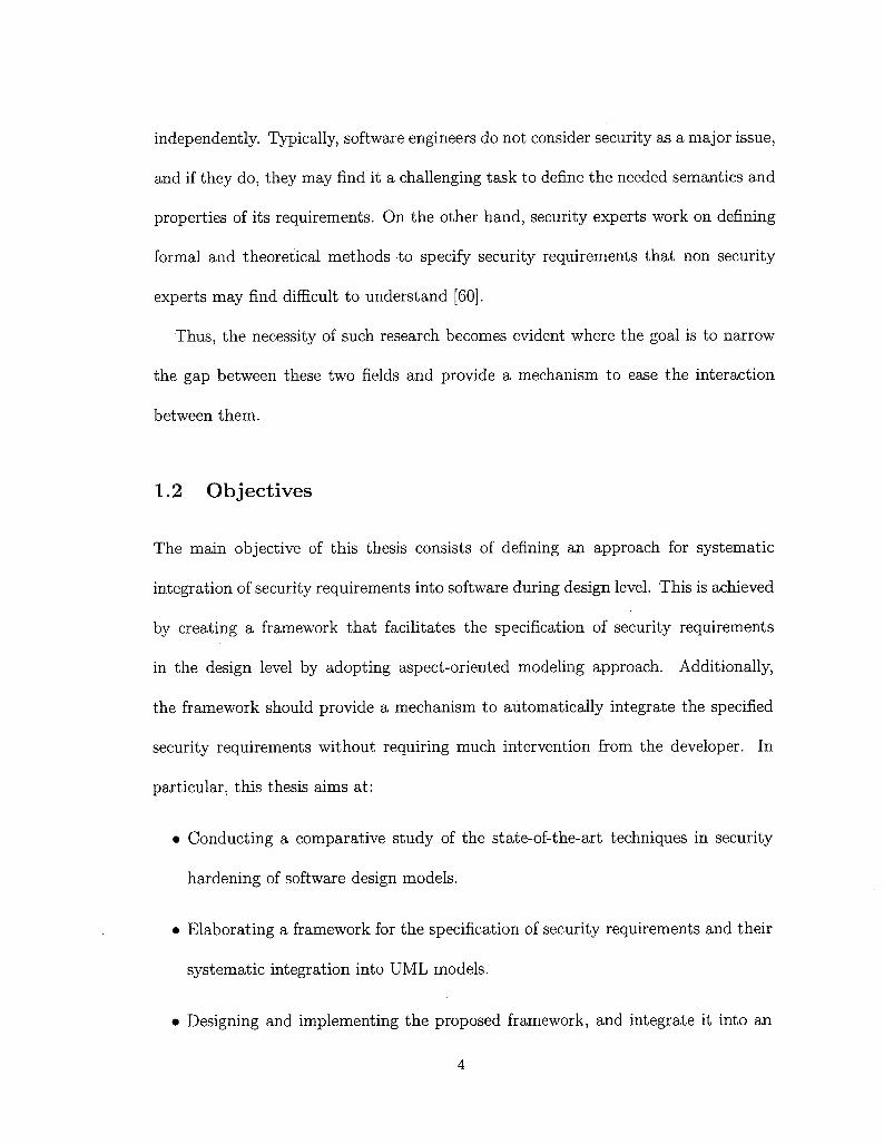
independently. Typically, software engineers do not consider security as a major issue,
and if they do, they may find it a challenging task to define the needed semantics and
properties of its requirements. On the other hand, security experts work on defining
formal and theoretical methods to specify security requirements that non security
experts may find difficult to understand [60].
Thus, the necessity of such research becomes evident where the goal is to narrow
the gap between these two fields and provide a mechanism to ease the interaction
between them.
1.2 Objectives
The main objective of this thesis consists of defining an approach for systematic
integration of security requirements into software during design level. This is achieved
by creating a framework that facilitates the specification of security requirements
in the design level by adopting aspect-oriented modeling approach. Additionally,
the framework should provide a mechanism to automatically integrate the specified
security requirements without requiring much intervention from the developer. In
particular, this thesis aims at:
• Conducting a comparative study of the state-of-the-art techniques in security
hardening of software design models.
• Elaborating a framework for the specification of security requirements and their
systematic integration into UML models.
• Designing and implementing the proposed framework, and integrate it into an
4

existing Integrated Development Environment (IDE).
• Validating the proposed approach through different case studies.
1.3 Contributions
This section lists the main contributions of this thesis in relation to the objectives
stated above. The main contributions of this thesis are:
• Elaboration of a UML extension to specify security requirements as aspects over
design models.
• Proposition of an instantiation mechanism that allows for the specialization of
generic security aspects for specific applications.
• Elaboration of model transformation rules that allow for the weaving of security
aspects into UML design models.
• Design and implementation of UML model weaver and its integration as a plug-in
within the Rational Software Architect (RSA) [39] modeling tool.
• Conducting a variety of case studies to demonstrate the feasibility of the pro-
posed approach.
1.4 Assumptions and Limitations
This section summarizes the main assumptions and limitations of this research work.
One main assumption of this research is that security aspects designed by security
5
specialist are assumed to be correct and complete. Security specialist has the re-
sponsibility to ensure that the aspect that he/she design is specified correctly and is
performing its operation appropriately.
In this research work, we focus on the most prominent types of UML diagrams
both in structural and behavioral views. Namely, we consider injecting security as-
pects into class diagrams, state machine diagrams, activity diagrams, and sequence
diagrams. Injecting security aspects into the other types of UML diagrams is con-
sidered a limitation. To overcome this limitation, an extension to the current model
weaver is required to include support for all other UML diagrams.
Another limitation of this work is the support for traceability of the removed ele-
ments. We provide support for traceability of the applied modifications that perform
adding or modifying an existing element. However, traceability of modifications that
perform removing operations is not supported.
1.5 Thesis Structure
This thesis is organized as follows. In Chapter 2, the necessary background required
by the reader regarding security requirements, aspect-oriented programming (AOP),
Model-driven architecture (MDA), and Unified Modeling Language (UML) are in-
troduced. In Chapter 3, different approaches to software security hardening such
as security design patterns, mechanism-directed meta-languages, and aspect-oriented
modeling (AOM) are discussed. In Chapter 4, the related work on model-to-model
6

transformation and model weaving are presented. Chapter 5 presents a novel aspect-
oriented modeling approach to specify security aspects using UML profiles. This
profile was developed inside our research project on Model-Based Engineering for Se-
cure Software and Systems (MOBS2). Chapter 6 is presented as a logical extension
to the previous one, where it describes how the defined security aspects are automat-
ically woven into UML design models. The complete framework of MOBS2 project
is presented in Chapter 7 along with some case studies to demonstrate the feasibility
of the approach. Finally, Chapter 8 presents the conclusion of this thesis.
7

Chapter 2
Background
This chapter introduces the main concepts needed to support the work developed in
this thesis. Firstly, in Section 2.1 a high-level overview of the main security prop-
erties is provided. In Section 2.2 a general explanation of what models are, what
they are good for, and how they can be used is provided. Then, the Object Man-
agement Group (OMG) standard for modeling languages Unified Modeling Language
(UML) [65] is presented. The classification of UML diagrams and the different views
of the models will be described as well. Later on, in Section 2.3, an introduction
of the necessary background in the area of Aspect- Oriented Technology is presented.
The main concepts of the Pointcut-Advice model are described. Finally, Section 2.4
introduces the OMG Model Driven Architecture (MDA) approach at the end of this
chapter.
8

2.1 Software Security
Software security is the process of enforcing security requirements into software, such
that it becomes resilient against various attacks and threats [56]. In this section, the
main concepts that make up the field of computer security are described.
2.1.1 Confidentiality
Confidentiality is the concealment of information or resources [H]. It denotes protec-
tion from unauthorized disclosure of information. In general, encryption is the main
mechanism used to ensure confidentiality.
2.1.2 Integrity
Integrity refers to the correctness and trustworthiness of data or resource [H]. In-
tegrity covers two aspects: data integrity and origin integrity. While the former
ensures that the content of the information is not altered, the latter deals with vali-
dating the source of the information.
2.1.3 Authentication
Authentication is the process of confirming the identity of an entity before granting
access to a resource [50]. Authentication can be achieved through different mecha-
nisms, such as using username-passwords, challenge-response protocols, biometrics,
or digital certificates.
9

2.1.4 Availability
Availability is defined as the ability to use a desired information or resource [H].
The availability becomes a security property, in the context that someone manage to
deliberately deny access to a service or data by making the system unavailable.
2.1.5 Non-Repudiation
Non-Repudiation is defined as the process of assuring that an entity participating in
a communication cannot deny having participated in all or part of the communica-
tion [50].
2.2 UML: The Unified Modeling Language
"The Unified Modeling Language (UML) is a visual language for specifying, con-
structing and documenting the artifacts of systems" [64]. According to the OMG
definition of UML, it is a visual language, which means it uses graphical notations to
describe and specify the different components of a given system. Before delving deeper
in explaining the UML language, it is first necessary to provide some definitions.
2.2.1 Terms and Definitions
What is a Model?
A Model is an abstract representation of a specification, a design, or a system, from
a particular point of view [86] . A model usually focuses on a certain aspect of the
system and omits all other details.
10

What is a Modeling Language?
A Modeling Language is a specification language that is generally defined by a syntax
and a semantics. It is meant to express information, knowledge, or systems. It can be
expressed in either a graphical or textual manner. The former uses diagrams to repre-
sent concepts and the relationships between them, while the latter uses standardized
keywords associated with parameters to make computer-interpretable expressions [36] .
What is a Meta-Model?
A Meta-Model is the creation of a set of concepts within a particular domain. It
describes the semantics of the modeling elements. By analogy, a model should conform
to its meta-model, as a program conforms to the grammar of a particular programming
language.
Why unified modeling language?
One of the objectives of modeling software systems is helping developers express
and discuss the problems and solutions involved in building a system. Usually, in
large sized systems, each developer is responsible for a certain component of the
system. However, the developer will need to have a good understanding of the other
components as well. In order to accomplish this, having a unified modeling language
that is widely used will facilitate the interaction between developers. Additionally,
this will result in reducing the development cost. For instance, if different modeling
languages are used by developers of different components for the same system, it will
require each of them more time to understand the details of the other's components.
11

Moreover, if a unified modeling language is used, it will ease the process of integrating
a new member into the development team, which will make the development wheel
move faster [86].
2.2.2 UML Structure
UML is an extremely extensive language. However, once its structure and concepts
are known, the size of the language no longer represents a problem. To be able to
understand the structure of the UML language, it is better to look at it from two
different dimensions (See Figurel).Others
¦ IN
J Stereotypes, model, j¡ information flow, Iprimitive, data types, '
templates, ObjectConstraint Language
(OCL). MetadataInterchange (XMI)
formatsIÍ?
V - r. · ~~\Figure 1: The Structure of UML [84]
First, one needs to distinguish between structural and behavioral elements. The
former represents the structure of the system while the latter is used to represent
the exact behavior of a given function in that system. The Others column presents
elements that refer to both structure and behavior [84] .
12
Structure
CJ)
Class^ diagram -• Component diagram
. Object diagramComposite structure diagram
"Deployment diagram - ". Package diagram· '
Behavior
Activity diagram; Use case diagramState machine diagram
Sequence diagramCommunication diagram
Timing' diagram -Interaction overview diagram
?¦ao Structure and Behavior model

In the second dimension, it is necessary to differentiate between Models and Dia-
grams. A Model represents the complete description of the system, while a diagram
represents part of the model from a certain point of view. For example, Figure 2 rep-
resents two diagrams for the same model. The diagram in part (A) shows the classes
with their attributes and the name of the associations between them, while the di-
agram in part (B) shows a different view of the model from the perspective of the
student with a complete list of attributes, operations, and association information.
Course
namenumbercredits
teach . register
Professor
name
departmentsalary
Student
nameiddepartment
Course
namenumbercreditsgetNameOsetNameOgetNumCreditsOsetNumCreditsOgetRegisteredStudentsO
register
Student
nameiddepartmentgetNameOsetNameOgetDepartmentOgetRegisteredCoursesO
Figure 2: Example of two different diagrams of the same model
2.2.3 UML Views and Concepts
In order to better understand the different functionalities and usages of UML dia-
grams, the classification of Philippe Kruchten who introduced the 4 + 1 view model
13

is adopted [52]. The 4 + 1 view model is adopted by many developers and archi-
tects because it facilitates the examination of different parts of an architecture, and
minimizes the complexity of the overall viewing of a system.
Each view in the 4 + 1 view model focuses on certain aspects of the system and
intentionally conceals the rest. A general description of each view and the corre-
sponding UML diagrams supported by each view are listed below [52]:
• Logical View: Describes the object model of the design, which focuses on the
functionality provided to the user by the system. The logical view contains
the following diagrams: class diagrams, sequence diagrams, and collaboration
diagrams.
• Development View: Describes the structure of modules and files in the system.
It is more concerned with software management and its organization. The UML
Package diagrams can be used to describe this view.
• Process View: Describes the dynamic aspects of the system. It shows the dif-
ferent processes and how they communicate with each other. The process view
deals with concurrency, distribution, performance, and availability. The UML
Activity diagrams represent this view.
• Physical View: Describes the mapping of the software to the hardware. In other
words, it is concerned with how the application is going to be installed and
executed in the physical layer. Deployment diagrams are used to depict this
view.
• Use Case View: This view is also called the Scenario view. It uses elements
14

from all other views to describe the functionality of the system and illustrate
what the system is supposed to do. The UML Use Case diagrams are used to
describe this view.
2.2.4 Extensibility Mechanisms in UML
UML allows the customization and extension of the UML meta-model without chang-
ing the existing meta-model. Thus, it provides a means to adapt the existing meta-
model and add new constructs that are specialized to a given domain or platform. [65] .
These new constructs are grouped in what is called Profiles. The common extensi-
bility mechanisms that are defined by UML are: (1) Stereotypes, (2) Tagged Values,
and (3) Constraints [75].
UML Stereotypes
A stereotype adds new semantics and properties to existing model elements. Typically,
a stereotype is depicted by a name surrounded by <S and 3>. A stereotype extends
an existing meta element by adding additional properties or tags that are specific to
a particular domain. These new properties are commonly called tagged values. The
collection of defined stereotypes for a common domain are grouped in what is called
Profile.
UML Tagged Values
Tagged Values are typically string pairs of tags/values. They are properties associated
with UML stereotypes that allow the extension of the properties of a given UML
15

element by creating new information in the specification of that element. The tag is
the name of the new property, and the value is the actual value of that property for
a given element. Moreover, it is important to differentiate between class attributes
and tagged values, as the value of the former applies to instances of the class while
the value of the latter applies to the element itself.
UML Constraints
Constraints are restrictions or conditions that should be imposed on a given element.
Usually, it is represented as a string expression in some textual language. UML defines
a standard constraint language called Object Constraint Language (OCL). However,
other languages can also be used.
2.2.5 OCL: Object Constraint Language
The Object Constraint Language (OCL) [63] is part of the UML standard. It is a
declarative language used to describe rules on UML models. These rules typically
specify conditions or constraints that must hold on elements of the UML model.
Additionally, since OCL 2.0 it has been extended to include support for object query
expressions on any model or meta-model [63].
2.3 Aspect-Oriented Paradigm
Object-oriented programming (OOP) has become the dominant programming paradigm
during the last few decades. It introduced the idea of using objects to represent differ-
ent components of a given system by breaking down a problem into separate objects,
16

and having each object grouping together data and behaviors into a single entity.
Such an approach aids in writing complex applications while maintaining comprehen-
sible source code [23]. However, some requirements do not decompose efficiently into
a single entity, and thus scatter in various places in the application source code. To
this end, aspect-oriented programming is introduced to solve this issue and separately
allows for the specification of the different concerns of a system [23] .
A sped-oriented programming (AOP) [48] is based on the idea of separation ofcross-cutting concerns. In other words, it separately specifies the different concerns
that cross-cut the application source code in many places, and then defines a mecha-
nism, called weaving, to compose the different parts into a coherent program. These
concerns may vary depending on the application domain; they can be functional or
non-functional, they may be high-level or low-level features. The objective of aspect-
orientation is to realize these scattered concerns into single elements called Aspects,
and eject them from the \'arious locations of the program [23]. AOP techniques have
emerged into various families of programming languages. They can be defined over
different languages, such as C, C++, PHP, and Java.
Many approaches were proposed in the literature to achieve the goals of aspect-
oriented programming, such as Pointent-Advice [47], Multi-Dimensional Separation
of Concerns [70], and Adaptive Programming [35] models. AlHadidi et.al. in [6],present an appropriateness analysis study for the different AOP approaches from
a security point of view. As a result, the pointcut-advice model was identified as
the more appropriate approach for security hardening. In the following subsections,
the main concepts related to the Pointent-Advice model are presented, as it is the
17

approach adopted in this research work.
2.3.1 Aspects
As mentioned previously, aspects are elements that encapsulate concerns that cross-
cut the core components of a given application. Typically, an aspect contains a set of
advices, i.e., behaviors, that need to be injected at specific points in the application
flow. These points are called join points in aspect-oriented terminology, and the set
of join points are called pointcuts. Additionally, the process of injecting the advice
into the application is commonly called weaving. Furthermore, other than advices,
aspects contain a set of pointcuts and introductions.
2.3.2 Join Points and Pointcuts
A point-cut is an expression that allows the selection of a set of points in the control
flow of the target application where advices need to be injected. Each point in this
set is called a join point. By analogy, a pointcut classifies join points in the same way
a type classifies values.
2.3.3 Advices
An advice is a piece of code, or behavior, that needs to be injected when the program
reaches a given join point (member of a pointcut expression) during execution. Each
advice needs to be associated with a specific pointcut that captures all the join points
in the program where this piece of code need to be injected.
18

2.3.4 Weaving
Weaving is the process of injecting the advice specified in the aspect at the identified
join points selected by pointcuts. Commonly, the inputs to the weaving process are
the application and the aspect programs, and the produced result is the combined
programs. Figure 3 shows a high-level representation of an aspect and the result of
the weaving process.
Advices
before WnteOadd AO
after VwiteOadd BQ
Application
Begin
i:=l+1:
WriteO; -"
End;
.JoinPoint
A) Before Weaving
Aspect Application
before WrrteO-addAO
after WnteO->add BO
B) After Weaving
Figure 3: Example of Weaving Process
2.4 MDA: Model Driven Architecture
Model Driven Architecture (MDA) [2] is a well-known approach that facilitates the
development of software systems. It was introduced by the Object Management
Group (OMG), which is an international, not-for-profit computer industry consortium
that originally aims at specifying standards for distributed object-oriented systems
19

and modeling standards [68]. The main goal of MDA is the separation of business
decisions from underlying platform technologies which gives more flexibility when
designing and architecting systems.
2.4.1 MDA Layers
The Model Driven Architecture approach defines four layers that aim at separating the
application logic from any underlying technology platform. These layers are defined
as follows [58]:
Computation Independent Model (CIM)
CIM model captures the user requirements and specifies what functionalities the
system should have without indicating any information about how it will achieve
these functionalities. In other words, at CIM level, the business requirements and the
domain of the system are described and all the structural details and the information
about the target platform are hidden as they are still undetermined.
Platform Independent Model (PIM)
PIM model is a business-oriented model that abstracts from platform issues, which
can survive the different technology changes. Additionally, PIM model satisfies the
main goals of MDA, portability and reusability. Moreover, at the PIM level, the focus
is on the operation of the system while hiding all the details that are required for a
particular platform. In other words, only the part of the specification that does not
change from one platform to another is shown.
20

Platform Specific Model (PSM)
PSM is derived from the PIM level by adding some platform-specific characteristics
to it. In this level, it is defined how the different functionalities in the PIM level
are realized on a certain computing platform. It is important to mention that it is
possible to generate multiple PSMs from one PIM, each of which corresponds to a
different platform.
Implementation Specific Model (ISM)
ISM is the actual generation of the executable code. Since the PSM already contains
all the details regarding the target platform, the generation of the code is somewhat
straightforward .
2.4.2 MDA Benefits
Following the MDA approach, while developing software and systems, is beneficial in
many ways. According to [83] the main advantages and benefits of using the MDA
approach is to achieve the following:
• Portability: Within MDA, portability is achieved through the development of
the PIM, which is, by definition, platform-independent. Using the PIM, and by
providing the corresponding transformation rules, the same PIM can be trans-
formed to multiple PSMs, hence, being portable from one platform to another.
• Productivity: In MDA, the focus of the developers is to design the PIM and from
where the PSM and code will be automatically generated. Therefore, developers
21
need not to worry about the implementation and platform details as they will
be added later by the PIM to PSM transformation. According to [51], this can
improve productivity in two ways: The developers will have less work to do as
the details of the implementation do not require to be specified as they will be
added later by the transformation definitions. Likewise, at the code level, the
developers will have less code to write as most of the code will be automatically
generated from the PIM and PSM levels. Therefore, by shifting the focus from
writing code to designing PIMs, the developers will have the opportunity to pay
more attention to solve the business problem at hand. To summarize, improving
productivity requires the use of tools that can automate the transformations
from PIM to PSM and later to code.
• Cross-platform Interoperability: Interoperability property defines the ability of
different systems to inter-operate and work together. MDA makes the concept of
cross-platform interoperability possible through the establishment of the PIM. In
MDA, one PIM is used to generate multiple PSMs, each of which is targeting a
different platform. Therefore, two different PSMs can intemperate as they both
originate from the same PIM. This is made possible by building bridges and
establishing links between the two PSMs. By having these bridges established,
the two PSMs that are targeted for different platforms can actually communicate.
• Maintenance and Documentation: As the PIM is used to generate the PSM and
the code afterwards, the generated code will be an exact representation of the
model. Therefore, the PIM can be considered as a high-level documentation
22

that is needed for any software system nowadays. However, the PIM will not be
discarded after generating the code but it will be maintained so that any future
modifications to the system will be made by modifying the PIM and regenerating
the new PSM and code [51].
2.4.3 MDA Transformations
The MDA guide [58] defines model transformation as: "the process of converting one
model to another model of the same system" . This process takes as input one or
more models that conforms to a specific meta-model and produces as output one or
more models that conforms to a given meta-model. Additionally, it is important to
mention that the transformation itself is also considered a model, i.e. it conforms to
a given meta-model.
Moreover, when transforming a PIM into a particular PSM, the input to the trans-
formation, along with the PIM, is a set of mapping rules that specify how each element
in the PIM will be transformed to the target PSM. The result of the transformation
along with the PSM is a record of transformation. The record of transformation con-
tains a map from elements of the PIM to the corresponding elements of the PSM. Also,
it shows which parts of the mapping were used for each part of the transformation.
When referring to model transformations, it is necessary to distinguish between
two types of transformations: model-to-model and model-to-code transformation.
Moreover, we usually refer to model-to-code transformations as model-to-text since
non-code artifacts may be generated, such as XML and documentation [18].
In the following we present some definitions and key concepts relevant to model
23

transformations:
• Endogenous and Exogenous transformations: Endogenous transformations are
transformations of models that conform to the same metamodel. In other words,
both the input and output model(s) conform to the exact metamodel. On the
other hand, exogenous transformations are transformations of models that con-
form to different metamodels [57].
• In-Place, Unidirectional and Bidirectional transformations: In-place transforma-
tion is a transformation that affects the same model. In other words, there is
no source model and target model, but only one model that is being modified
by the transformation. However, the unidirectional transformation must have
source and target models where the target model is generated or updated based
on the source model. In other words, the execution of the transformation can be
done in one direction only. In contrast, bidirectional transformation is when the
execution can be done in both directions, that is transform the source model to
the target model and transform the target model to the source model [57].
• Transformation Definition and Transformation Rules: As mentioned previously,
model transformation is the process of generating a target model from a source
model. This transformation is specified in what is called transformation defini-
tion. Transformation definition consists of a set of rules, each of which specifies
how the elements in the source model will be transformed into elements in the
target model.
• Horizontal and Vertical Transformation: MDA supports two different directions
24

of transformations; horizontal and vertical transformations. Horizontal trans-
formations may occur inside a single layer of abstraction, that is, the level of
abstraction of the source and target model are always the same. For example,
merging a group of PIMs or PSMs together will result of a new model where its
level of abstraction remains the same. However, vertical transformation is when
there is progression from one level of abstraction to a more specialized level,
such as going from PIM level to PSM, where more information about a specific
platform is added.
PIMLevel
iPPlÎ PIM2 PIM3
HorizontalTransformation
VerticalTransformation Ï
PSM ^-Level PSM1
Figure 4: Horizontal and Vertical Transformations
2.4.4 QVT: The Standard Language
QVT (Query/ View/ Transformation) is the standard defined by the Object Manage-
ment Group (OMG) for model transformation. It consists of three components: two
declarative (Relations and Core) and one imperative (Operational Mappings) [66] .
25

The relations language implements the transformation by providing links that iden-
tify relations between elements in the source model to elements in the target model.
The core language is also a declarative language; it is simpler than the relations lan-
guage. It is actually used to specify the semantics of the relations language. These two
languages are good for simple transformations where the source model and the target
model have a similar structure. However, when it comes to more complicated and
sophisticated transformations where elements in the target model are being built with
no direct correspondence with elements in the source model, declarative languages
can be a limitation. Thus, the need for an imperative language becomes a must.
Therefore, QVT proposed the third language, which is the operational QVT [53].
26

Chapter 3
Security Hardening of Software
Design Models
In this chapter, we present the existing work that has been conducted in the state-of-
the-art on security enforcement during the design phase of the software development
life cycle. Three main approaches are typically adopted to design UML security
enforcement mechanisms. These are security design patterns, mechanism-directed
meta-languages, and aspect-oriented modeling.
In section 3.1, we present various approaches that use predefined security de-
sign patterns to enforce security into existing applications and systems. Section 3.2
presents approaches that define new meta-languages to design security enforcement
mechanisms. Section 3.3 presents a study of the existing approaches that adopt
aspect-oriented technologies for software security enforcement at UML design level.
Finally, in section 3.4, the findings of this chapter are summarized.
27

3.1 Security Design Patterns
Security design patterns are well-defined solutions to a recurring security design prob-
lem. They encapsulate the knowledge of a security expert regarding a specific security
problem by defining a working solution to this problem. Different security patterns
have been proposed in the literature targeting various security problems at different
levels of the software development lifecycle. A detailed study of different security
patterns can be found in [10, 27, 49, 54, 78, 89] .
Yoshioka et al. [89] provide a survey of approaches for specifying security patterns
that are categorized according to the different levels of the software development
life cycle. During the requirement phase, the different assets of the system must be
identified as well as the purpose of protecting them. This will aid in the development
of the right means to protect them. Additionally, during the requirement phase, the
security requirements need to be specified alongside the system requirements. Security
patterns for the design phase cover the decisions relating to the architecture as well
as the detailed design of a system. In this phase, various security functions need to
be designed as patterns to protect the assets specified in the requirement phase. For
instance, such patterns may cover functions such as authentication, authorization,
and access control. Finally, in order for the implementation phase to create secure
software, one must account for human-error factors. Mistakes caused by programmers
when writing program code may result in security bugs. Therefore, implementation
level security patterns are needed to guide programmers while writing programs with
guidelines illustrating the required techniques to write secure programs [89] .
28
A survey of different modeling approaches for applying security patterns during the
stages of requirement analysis and design is presented in [10]. Bandara et ai, compare
different security modeling approaches and classify them into three categories: Design-
oriented, goal-oriented, and problem-oriented.
Kienzle et al. [49] present 29 security-related patterns, three of which are mini-
patterns. The presented patterns are classified into two categories: Structural and
procedural patterns. The former contains patterns that can be implemented in an
application; they include diagrams that describe both the structure and interaction of
the design pattern. On the other hand, the procedural patterns are used to improve
the development process of security-critical software [49]. The patterns presented
in [49] focus on the security policies of web applications.
Fernandez et al. [27] suggest the need for a series of pattern languages, each tar-
geting one level of the architectural levels of a system. In [27] , a pattern language for
abstract models that defines security constraints at high architectural level of the ap-
plication is proposed. The security patterns are illustrated using textual templates,
as well as UML diagrams. Three security patterns are discussed: Authorization,
role-based access control, and multi-level security.
Schumacher et al. [78] present network-related security patterns, such as network
authentication protocol, network encryption protocol, cryptographic protocol, and
virtual private networks.
29

3.2 Mechanism-Directed Meta-Languages
This approach focus on extending UML meta-language using standard extension
mechanisms, such as stereotypes and tagged values, in order to handle the spec-
ification of security concerns. Many contributions in the literature proposed new
meta-languages specialized to design specific security solutions. The majority of these
contributions target the specification of access control policies, such as Role-Based
Access Control (RBAC) [76]. Other security requirements such as authentication
and authorization have been considered as well. In the following, we present a brief
overview of these contributions.
SecureUML [55] is a modeling language used to specify access control policies and
help integrating them into application models defined with UML. It is based on an
extended model for role-based access control (RBAC) with additional support for
specifying authorization constraints. Moreover, SecureUML meta-model is defined as
an extension to the UML meta-model. It defines a vocabulary for specifying various
concepts related to access control, such as roles, users, and permissions.
Jan Jürjens presents in [46] an approach, called UMLsec, based on extending
UML for secure systems development. UMLsec is defined as UML profile using the
standard extension mechanisms of UML. It assists in the development of security-
critical systems by annotating UML models with stereotypes representing different
security requirements such as secrecy, encryption, and fair exchange.
Epstein et al. [24] explored the possibility of using UML to model RBAC policies.
Their work targets the model of Role-Based Access Control Framework for Network
30

Enterprises (FNE). FNE model is represented by seven abstract layers. These seven
layers are divided into two different groups, who are responsible to engineer them.
Each of the FNE layers is represented using UML notations with a set of new defined
stereotypes. Epstein et al. approach is one of the first contributions to present UML
extension for role engineering. However, their approach is limited to a specific model
of RBAC, RBAC FNE. Moreover, some RBAC concepts such as least privileges and
separation of duties are not siipported in the FNE model. In addition, they provide
neither role engineering framework, nor a methodology to implement it.
Doairet al. in [21], and [22] address the issue of incorporating different secu-
rity mechanisms into UML. In [21] they target the inclusion of Mandatory Access
Control (MAC) concepts into different UML diagrams, such as, use case, class, and
sequence diagrams. Different security assurance rules (SARs) have been proposed to
enforce MAC for UML. In their approach, SARs are checked in real-time as the de-
veloper is designing the models. In addition, post design security assurance checking
is also supported. Furthermore, in [22], Doan et al. propose an approach to integrate
RBAC, MAC, and lifetimes into UML designs for time-sensitive applications. They
suggest that integrating security concerns into an application must be accomplished
by tracking the entire design process. This means capturing all the design instances
over time and not focusing only on the current design state. This feature of design
instances tracking allows the software designer to return to a previous design version
that satisfies particular security constraints.
Ray et al. [73] address the issue of integrating different access control policies, such
31

as RBAC and MAC into a single hybrid model. They analyze the potential unde-
sired properties and conflicts that may arise from such integration. In this approach,
parameterized UML is used to specify and compose access control models. However,
they do not propose how this approach can be used to design secure software. Addi-
tionally, no tool support is provided, as the process of model integration and conflict
detection is done manually.
3.3 Aspect-Oriented Modeling
The applicability of aspect-oriented techniques to specify security requirements has
been heavily studied in the literature both at the design and implementation levels.
Following the success of aspect-oriented programming (AOP) techniques in modular-
izing crosscutting concerns at the implementation level, various contributions worked
on abstracting the AOP concepts and adopting them to the design level as well. Many
contributions focus on abstracting AspectJ [47], the de-facto standard for AOP, into
modeling level [25,81,87]. Yan et al. [87] propose a bottom up approach by introduc-
ing an AspectJ meta-model in order to support AspectJ software modeling. Their
approach depends on extending the UML meta-model. First, they designed a Java
meta-model by tailoring UML meta classes to Java concepts. Then, the Java meta-
model was extended into AspectJ meta-model. This work aims at narrowing the
gap between conceptual modeling of aspects and their concrete implementation in
AspectJ. However, the main limitation of such approach is the fact that extending
UML meta-model requires either modifying existing UML case tools, or implementing
32

new ones in order to provide support to the newly defined UML meta classes. Apart
from Yan et al. approach [87], some contributions suggest the use of standard UML
extension mechanisms, such as stereotypes and tagged values to provide support for
AspectJ constructs in the modeling level [25,81].
Evermann [25] , proposes a meta-model for modeling AspectJ as UML profile using
UML extension mechanisms. This work is considered the first complete proposal for
specifying AspectJ in UML. Stein et al. [81] present a design notation for AspectJ
programs based on UML. They provide representation for various AspectJ constructs
as stereotypes. In addition, weaving mechanisms of AspectJ are implemented in
terms of UML collaborations, which are used to describe the behavior of different
operations.
While the previous contributions helped in elevating AspectJ concepts to the design
level, they are yet programming language dependant and do not cover all AOP con-
cepts. Therefore, other contributions worked towards generic aspect-oriented model-
ing approaches that are independent of any programming language. Chavez et al. [13]
propose an extension to the UML meta-model for aspect-oriented modeling support.
In their approach, aspects are defined as parameterized model elements that contains
a set of cross-cutting interfaces. A cross-cutting interface represents join points, and
contains a set of operations that model cross-cutting behaviors over these join points.
Moreover, several surveys have been published in the recent years comparing dif-
ferent aspect-oriented modeling (AOM) approaches [12, 69, 74, 77] based on different
evaluation criteria. In the following we concentrate on contributions related to AOM
and security.
33

Gao et al. [88] present an aspect-oriented design approach for designing flexible
security systems. They illustrate their approach by specifying RBAC access control
to implement functional CORBA Access Control (AC) mechanism. RBAC0 (Core
RBAC) is considered the base model and the different RBAC extensions are con-
sidered as aspects. Thus, through aspect-oriented mechanisms different models of
RBAC, such as RBACi (Hierarchical RBAC) and RBAC2 (RBAC with constraints)
can be incrementally constructed from the Core RBAC. Composition rules are based
on AspectJ rules, and models are specified by extending UML notation with stereo-
types.
France et al. [29] describe an AOM approach that can be used to produce logical
Aspect-oriented Architecture Models (AAMs) that show how different concerns can
be described independently of any underlying technology. In this approach, AAM
models consist of: (1) a set of aspect models, (2) a primary architecture model, and
(3).composition directives to define how aspect models are composed with the primary
model. Aspect models are defined as general patterns represented using UML diagram
templates. These patterns are instantiated by binding the template parameters to
actual application values to produce context-specific aspects before composing them
with the primary model
Ray et al. [72] propose an aspect-oriented modeling approach for specifying access
control concerns as aspects and weaving them with primary models. In this approach,
two different perspectives are identified for modeling access control aspects; structural
perspective and dynamic perspective. The former presents the different entities con-
strained with the access control policies and the relations between them, while the
34

latter defines the constraints imposed on behaviors by the access control policy. Tem-
plate forms of UML structural diagrams, such as class diagrams, are used to model
the structural perspective, while template forms of interaction diagrams are used for
the dynamic perspective.
Georg et al. [32, 33] describe an aspect-oriented methodology for designing secure
applications. First, they evaluate the application against attacks that are known to be
common for such applications. The attack is modeled as an aspect that is composed
with the primary model to generate a misuse model. The misuse model is evaluated
to indicate whether the level of compromise in the application is acceptable or not.
Then, the appropriate security mechanisms, modeled as aspects, are incorporated
into the application. The final result is reassessed to guarantee that it is resilient to
the given attack.
Dai et al. [19] propose a new approach for modeling and analysis of non-functional
requirements as aspects in a UML based architecture design. An aspect oriented
approach called, the Formal Design Analysis Framework (FDAF), was proposed to
support the design and analysis of non-functional requirements defined as reusable
aspects for distributed real-time systems using UML and formal methods. The FDAF
approach presents a UML extension to capture different aspects, such as performance
and security aspects on UML designs using stereotypes. The extended design, i.e. the
woven model, is then automatically transformed into an appropriate formal notation,
such as Promella, which is then analyzed using existing tool support, such as SPIN
model checker, to determine whether or not the specified non-functional requirement
is met by the given aspect design.
35

Zhang et al. [90] propose an aspect-oriented modeling approach for enforcing access
control in Web applications. This approach extends the UML-based Web Engineering
(UWE) meta-model to introduce the concept of aspects. The behavior of navigation
nodes in the web application is specified using state machines. The aspect is mod-
eled as UML package, which contains a set of state machine diagrams specifying the
behavior of the access control rules to be enforced.
3.4 Summary
In this chapter, we presented three different approaches for enforcing security mecha-
nisms at the design level: Security design patterns, mechanism-directed meta-languages,
and aspect- oriented modeling. We have seen that security design patterns mainly pro-
vide textual description for solving a given security problem. They provide high-level
and abstract solutions that generally lack the behavior of the security mechanisms. In
addition, design patterns are described in a way that requires manual implementation.
Thus, automatic enforcement of security mechanisms cannot be achieved.
Moreover, we observed that current approaches that adopt the use of dedicated
meta-languages to specify security concerns mainly focus on access control policies.
Additionally, this approach seems to be ineffective for non-security experts as it re-
quires continuous interaction with security experts during software design in order to
ensure the appropriate enforcement of security requirements.
The third approach discussed in this chapter is aspect-oriented modeling. This ap-
proach overcomes the limitations observed in the previous approaches. By adopting
36

aspect-oriented techniques, security experts independently specify security enforce-
ment mechanisms as generic aspects and provide them for software developers to
specialize them to their application. Moreover, aspect-oriented techniques provide a
way to automate the process of integrating security solutions with the application
primary model.
We have seen from the literature review of aspect-oriented modeling that there
exist different mechanisms to specify aspects at the model level. Some contributions
suggest extending the UML meta-model by adding new meta classes to specify aspect-
oriented concepts. This technique suffers from implementation difficulties, as new
UML case tools need to be implemented with the support of the newly specified meta
classes. In addition, interoperability may become an issue because existing UML case
tools will lack the support of the new UML meta-model extension and will need to
be manipulated in order to extend its support to the newly defined meta classes.
The. other technique to implement the support of aspect-orientation in UML is to
make use of the standard UML extension mechanisms: stereotypes, tagged values,
and constraints. This approach seems to be a better solution as it overcomes the
limitations identified in the previous approach. Thus, we have chosen to adopt this
approach when specifying the UML aspects as we will see in Chapter 5.
37

Chapter 4
Model Transformation and Model
Weaving
In this chapter, we explain the existing work in the area of model transformations and
model weaving. Model transformation (MT) is a new concept emerging within the
Model Driven Architecture (MDA) [2] approach focusing on the process of generating
target model(s) from source model(s). Within the MDA approach model transfor-
mation can be divided into two categories: Model-to-Model transformation (M2M)
and Model-to-Text transformation (M2T) [58]. The former is used to transform mod-
els from PIM level to PSM level, while the latter is used to transform models from
PSM level to code level. In this research, we are interested in the first type, i.e.
model-to-model transformation. Thus, throughout this thesis when we say model
transformation we are referring to model-to-model transformation in particular.
Many classifications of model transformation approaches exist in the literature [18,
57,79]. Some classify them according to the nature of the transformation language,
38

whether it is declarative, imperative, or hybrid (combination of declarative and im-
perative). Others base the classification on the techniques used to implement such
transformation. Either by direct manipulation of the model using general purpose
programming language, or by dealing with some intermediate representation of the
model, or by using dedicated model transformation languages or meta-modeling lan-
guages.
Czarnecki and Helsen [18] provide a classification of model transformation ap-
proaches that has been adopted by many people in the software engineering commu-
nity. In the following, we give a summary of their classification while pointing out
the strengthes and limitations of each approach.
• Direct Manipulation Approach: This approach adopts object-oriented techniques
to transform models using general purpose programming language, such as Java.
This programming language will manipulate the internal representation of the
models using specialized application programming interfaces (APIs). Since this
approach uses any general purpose object-oriented language, the overhead of
learning new language is minimal. However, since the language is not specially
designed to handle model transformation, many properties and features, such as
scheduling processes, are implemented from scratch.
• Relational Approach: This approach is considered a declarative approach where
the types of the source and target elements need to be explicitly specified along
with a constrained relation between them. Thus, this approach does not allow in-
place transformation. One implementation of this approach is the use of logical
39

programming languages. In relational approaches, target elements are created
implicitly, unlike the first approach where target elements need to be explicitly
created. For instance, when the transformation is executed the different relations
are verified and then the target model contents are automatically created [17].
• Graph Transformation Based Approach: It is a declarative approach based on
the theoretical work done on graph transformation. It depends on two patterns,
left hand side (LHS), and right hand side (RHS) patterns. The LHS pattern
is used as a matching pattern against the model we need to transform. While
the RHS pa,ttern will replace the matched patterns in that model. The main
limitation is the non-determinism of rule scheduling [42] as we will explain in
Section 4.2.6.
• Structure Driven Approach: The structure driven approach consist of two phases.
The first phase where the hierarchial structure of the target model is being
created. The second phase where we set the different attributes and references
in the target model. In this approach, the user specifies the transformation
rules, however, he/she does not have any control over the rule scheduling as it is
determined by the framework. OptimalJ [4] is an example of an implementation
of the structure driven approach.
• Hybrid Approach: The hybrid approach is a combination of any of the previously
mentioned approaches. For example, the standard language QVT [66] is consid-
ered a hybrid approach as it contains three components such that two of them
adopt a relational approach, while the third is operational. Another example of
40

a hybrid approach is ATL [1] where a single ATL transformation rule may be
fully declarative, hybrid, or fully imperative.
In this chapter, we explore the area of model transformation presented by the
Object Management Group (OMG) as part of the MDA framework in [2]. First, in
Section 4.1 the different applications of model transformations in different domains
are described. Next, in Section 4.2 the different model transformation languages
and tools are studied. Section 4.3 presents the state-of-the-art work regarding the
application of model transformation techniques to weaving aspect-oriented models.
Finally, we summarize this chapter in Section 4.4.
4.1 Applications of Model Transformations
Model transformation (MT) has become a useful technique that can be incorporated
in various development methodologies. In this section, we highlight some important
scenarios of model transformations in different application domains.
In the context of Model Driven Software Development(MDSD) [80], a software
system is developed through an iterative modeling process where the system model
is refined repeatedly until it reaches a stage where sufficient details to implement the
system are specified [53]. The refinement process aims at transforming the system
from abstract models to more concrete ones.
Another example where model transformation becomes useful is when adopting
41

Aspect-Oriented Software Development (AOSD) methodology [9]. AOSD is an emerg-
ing technology where the aim is to isolate non-functional requirements from the sys-tem main functionalities. However, at some point these isolated concerns need to be
composed "woven" with the primary concern to produce a working system. Similarly,in the context of Product Line Software Engineering (PLSE) [71], which is a software
development technology targeting the creation of a portfolio of closely related prod-ucts that share common assets with variations in features and functions. In PLSE,
the different features that compose a given product need to be integrated together
to produce the final product. This integration of different software features can alsobe considered as a transformation process. Figure 5 illustrates the refinement and
composition processes in different software development methodologies.
Abstract
M
oM'
Concrete
a) Model Driven SoftwareDevelopment (MDSD)
Primary model Concern 1 Concern ?
Composed model
b) Aspect-Oriented SoftwareDevelopment (AOSD)
Primary modelM
Library ofFeatures
QO1.
T3:
M'
Productl
c) Product Line SoftwareEngineering (PLSE)
Figure 5: Transformation Examples
Moreover, software refactoring, code generation, and model translation are more
examples of applications to model transformation. Software refactoring is a software
42

transformation that preserves the software behavior, but enhances its internal struc-
ture such that it makes it easier to understand and maintain. Additionally, model
translation is when the source model expressed in one language is transformed to an-
other model expressed in different language; for example, transforming UML models
to artifacts that can be analyzed formally using formal analysis tools [30]. Table 1
summarizes the examples of model transformation applications with the correspond-
ing direction of the transformation.ExampleSoftware Refinement (MDSD)Aspect Weaving (AOSD)Feature integration (PLSE)Software RefactoringCode GenerationModel Translation
Transformation DirectionVertical
HorizontalHorizontalHorizontal
VerticalVertical
Table 1: Examples of Model Transformation.
4.2 Model Transformation Languages
With the increasing interest in the MDA approach, many model transformation tech-
niques and languages have been proposed. Model transformations can be achieved
using different approaches, one approach suggests the use of APIs combined with a
general purpose programming language. For example, the Java meta-data interface
(JMI) [5] is one of the existing APIs that facilitates model access and manipula-tion. Using this method there is no overhead to learn a new language since known
object-oriented languages can be used. However, since the language is not designedto handel model manipulation all transformation rules and transformation scheduling
must be implemented from scratch [42]. Therefore, transformation languages should
43

be the solution as they have better performance and portability. In the sequel, we
will describe the state-of-the-art in model transformation languages.
4.2.1 Atlas Transformation Language (ATL)
The ATL language was developed in the INRIA labs [41]. It is a hybrid language that
is a mix of declarative and imperative constructs. This language is not compliant with
the OMG standard for model transformation QVT, although, it implements similar
concepts and functionalities. It consists of three level architecture: Atlas Model
Weaver (AMW), ATL, and ATL Virtual Machine. Atlas Model Weaver (AMW)
[26] supports the creation of links between model elements and then saves theselinks in a separate model, commonly referred to as the weaving model. ATL is the
transformation language, it supports unidirectional transformations and it is used to
write ATL programs, which are going to be executed by the ATL virtual machine
(VM). In addition, the ATL language support automatic creation of traceability linksbetween source and target models. Explicit rule scheduling is supported as well [45].
4.2.2 Open Architecture Ware (oAW)
Open Architecture Ware (oAW) [3] is a modular Model Driven Architecture (MDA)/
Model Driven Development (MDD) framework that supports model transformations
using a language called Xtend. The latter is an imperative language that performs
the transformation of models by running a sequence of statements. These statements
are called within a workflow, and are executed by a workflow engine. Moreover,
oAW provide special support for aspect-orientation through a weaving tool called
44

XWeave [34], which is capable of weaving two models together. However, within oAWframework there is no support for traceability between input and output models.
4.2.3 IBM Model Transformation Framework (MTF)
IBM MTF [20] was developed in order to experiment with QVT related concepts.
MTF allows the specification, in a declarative way, of transformations as a set of
relations among models. These relations are expressed using a language called Rela-
tion Definition Language (RDL). RDL is used to define the relations between classes.
For instance, a relation can be established between classes that have a matching at-
tribute. The transformation engine will then parse and evaluate these relations. MTF
supports bi- directional transformations, which mean that the transformations can be
executed in any direction; transforming the source model to the target model and
vice versa. However, it allows the generation of automatic traceability links but in
the other hand it does not allow user accessibility to it.
4.2.4 Kermeta
Kermeta is a modeling and programming language that defines both the structure
and behavior of meta-models. It is provided by Triskell Project, a research project
from INRIA labs [41] . Kermeta is considered the first executable meta-language
that can be used for different purposes, such as model and meta-model prototyping
and simulation, verification and validation of models against meta-models, and model
transformations [61]. The transformation itself is written as an object-oriented pro-
gram that manipulates models. In contrast to other languages, the input and output
45
models and meta-models must be loaded and saved explicitly by the programmer.
Additionally, Kermeta does not provide any built in support for traceability.
4.2.5 QVT Operational (QVTO)
QVT (Query/View/Transformation) is a standard defined by the Object Manage-ment Group (OMG) for model transformation [66]. The Eclipse modeling project
provides an implementation of the standard QVT operational through its M2M [43]
open source project. Unlike other tools and languages that only support some con-
cepts of the QVT standard, Eclipse QVT Operational (QVTO) implements the finaladopted specification. QVTO is an imperative language, with an automatic support
for traceability between models. To write a transformation using QVTO, we need
to specify the input and output models, an entry point to our transformation, anda set of mapping rules that are going to be executed in a sequential manner. Ad-
ditionally, QVTO uses some object-oriented techniques such as inheritance, wheretransformations can inherit from each other, and overriding of mapping rules.
4.2.6 Comparative Study
The field of model transformation is relatively new and thus the support for transfor-
mation languages is increasing through time. In the previous subsections, we high-
lighted some of the existing transformation approaches and languages while pointingout the different features that each of them provide.
As our objective in this research work is to provide a methodology for automatic
integration of security concerns "aspects" into design models, the technology of model
46

transformation can be of a great value. Moreover, one of the great challenges we faced
was to select the appropriate language from the pool of available transformation
languages that best suits our needs. To do so, we identify some characteristics that
are desirable in the transformation language. The following is a description of these
characteristics:
Transformation Approach: While studying the existing transformation languages,
we found them to be either declarative, imperative, object-oriented, or hybrid. Declar-
ative languages are good for simple transformation that is based on establishing rela-
tions between the input and output models. Imperative languages are more suited for
complex transformations as they describe the different steps that need to be executed
to transform the source model into the target model. Hybrid languages are those who
combine both declarative and imperative constructs. Indeed, the process of weaving
aspects into base models is not always based on establishing direct relations between
the models. In fact, it may require complex operations that declarative languages
fail to achieve. Thus, imperative or perhaps hybrid approaches will give us more
expressiveness in terms of language constructs when dealing with aspects weaving.
Rule Scheduling: It is the order in which transformation rules are applied on
the models while executing the transformation. As defined in [18], rule scheduling
in transformation languages can be categorized as follows: (1) Implicit scheduling,
which is based on the implicit relations between rules, (2) Explicit scheduling, which
is based on explicit specification of rule ordering. Additionally, explicit scheduling
can be further classified into explicit internal and explicit external scheduling. While
the former is defined using explicit rule invocations, the latter depends on defining
47

the scheduling logic outside the transformation rules by the means of some special
language. Furthermore, in the context of aspect weaving, we need to have full control
over the order in which the rules are applied. Such control will help in handling
different issues, such as conflicting advices where the application of one advice depends
on the application of the other.
Traceability Support: The tool has to provide support for traceability between
models. It should provide a trace record that shows links between elements in the
source model to elements in the target model. This is important to be able to track
what aspect applied what modification on the base model. In addition, traceability
is of high value for documentation purposes.
Standardization: The Object Management Group (OMG) defined QVT (Query/Vi-
ew/Transformation) as a standard language for model transformations. It is impor-
tant to choose a language that is based on a standard and thus support all other
relevant standards, such as UML, MOF, OCL, etc. This will provide portability
for the weaver through different UML case tools, which provide support for OMG
standards.
Table 2 summarizes the different characteristics with contrast to the specified
transformation tools.
By comparing the different tools with regards to the specified requirements, we
conclude that QVTO is the best language to use as it meets our requirements.
48

Tool/Language Approach Rule Scheduling Traceability Standardization
ATL Hybrid Explicit internal yesoAW Imperative Explicit externalMTF Declarative Implicit yesKermeta Imperative Explicit internal no
QVTO Imperative Explicit internal yes yes
Graph-basedlanguage
Declarative Explicit external no
General-purposeprogramming language
Imperative Explicit internal no
Table 2: Comparison of Model Transformation Languages and Tools
4.3 Related Work on Model Weaving
A lot of work has been published recently proposing different approaches for weav-
ing aspects into design models [15,28,31,34,38,59,91]. Some adopt symmetric ap-
proach [28,38], where they do not distinguish between aspects and base models, while
others support asymmetric approach [15,31,34,59,91], where there is a clear distinc-
tion between the aspect model and the base model during the weaving. What follows
is a presentation of the related work done in this field.
XWeave is a model weaver proposed in [34] that is able to weave both models
and meta-models. The tool takes a base model and one or more aspect models as
inputs and weaves the aspect elements into the base model to produce the woven
model. Pointcuts used by XWeave are expressed using oAW, an expression language
based on OCL. The main limitation of XWeave is the fact that it only supports
additive weaving. The removal or replacement of existing base model elements is not
supported.
Motorola weaver [91] is one of the stable weavers that was developed in an indus-
trial environment as a plug-in for Telelogic TAU. It is a model transformation engine
49

that enables weaving aspects into executable UML state machine models. It supports
two types of pointcuts, action pointcut and transition pointcut. However, this weaver
is based on the Telelogic TAU G2 implementation, therefore, it is tool-dependent and
not portable. Additionally, it only supports the weaving of one type of UML model,
which is the state machine model.
Fleurey et al. [28] present a generic tool for model composition called Kompose,
which is built on top of Kermeta. It focuses only on the structural composition of
any modeling language described by a meta-model, thus it does not support weaving
of behavioral advices. In addition, it adopts a signature comparison mechanism to
match elements during the weaving, which makes the specified aspects application
specific rather than generic.
MATA [85] is a tool for modeling and composing UML models based on graph
transformation formalism. The aspect and base model are represented using UML
diagrams and the composition of class, sequence, and state machine diagrams are
supported. Since composition is based on graph transformation, MATA requires the
presence of a graph rule execution tool. The UML base model is transformed into
an instance of type graph. Similarly, the MATA model is transformed into AGG
graph rule that is automatically executed on the base graph. The result will then
be transformed back to UML model. MATA is one of the few tools that support
both structural and behavioral composition. However, the composition or weaving is
not done on UML models directly, but rather is performed by executing a graph rule
through a graph execution tool.
The AMW (ATLAS Model Weaver) [26] is a tool developed by the ATLAS group,
50
INRIA for establishing relationships, i.e. links between models. These links are stored
in a model that is called weaving model. It is created conforming to a specific weaving
meta-model, which enables creating links between model elements and associations
between links. However, these links are not automatically generated, but it requires
continuous interaction with the developer to build the weaving model. Indeed, AMW
can be considered as a declarative approach as it is based on establishing relation-
ships between different elements in the input models. Additionally, AMW deals only
with the XMI representation of models and does not handle the manipulation of the
corresponding graphical representation.
Furthermore, GeKo (Generic composition with Kermeta) [59] is another AOMapproach that can be applied to any well-defined meta-model and supports both
structural and behavioral composition. It uses a Porolog-based pattern matching
engine, implemented in Kermeta [62], to automatically identify join points. In this
approach, first the meta-model and the base model are converted into a Prolog knowl-
edge base, and pointcuts are transformed into Prolog queries. Then, it executes the
queries on the knowledge base and finally converts the results back into its original
structure [59]. Adding, removing and updating objects in the base model is supportedby this approach. However, it does not support clear traceability, meaning that the
impact of an aspect on the base model is not visualized. Therefore, after weaving it
is not possible to clearly recognize the effects of a particular aspect on the model [59].
Fuentes and Sánchez [31] propose an approach for designing and weaving aspect-
oriented executable UML models. A UML profile called AOEM, is elaborated to
51

support aspect-oriented concepts along with a model weaver for such profile. More-
over, they define the weaving process as a chain of model transformations. However,
no model transformation language is used. Instead, they use Java and standards like
XSLT and XPath to directly manipulate the XMI representation of the models. In-
deed, implementing model weaver using these languages raises some scalability and
maintenance problems.
Cui et al. [15] propose an aspect-oriented modeling approach for modeling and
integrating UML activity diagrams. Primary models are modeled as activity diagrams
while aspect models, consisting of pointcut and advice models, are depicted as activity
diagrams extended by a set of stereotypes and tagged values. In [15], two types
of cross-cutting concerns are handled: parallel and sequential cross-cutting concerns.
Parallel aspects are uncritical features that their execution does not affect the behavior
of the primary model. Sequential aspects on the other hand are critical features that
their execution results may influence the processes in the primary model.
Hovsepyan et al. [38] propose an approach called Generic Reusable Concern Com-
positions (GReCCo) for composing concern models. It is a symmetric approach, in
the sense that both concerns are treated similarly. In addition, composition of class
and sequence diagrams are supported. Different concerns are specified as generic
concerns independent of any context to support reusability of concerns. In order to
compose two concerns, a composition model is specified which provide directions to
the transformation engine on how to compose the two models. The GReCCo proto-
type is implemented using ATL transformation language. Since concerns are specified
52

as general models, the specialization to a particular context is done in the composi-
tion model. However, this suggests that for each composition operation a separate
composition model needs to be specified, which may be a costly task in terms of effort
and complexity. Moreover, although the issue of reusable concerns is solved in this
approach, the same problem arises again in the context of composition models.
4.4 Summary
In this chapter, we presented the state-of-the-art together with a comparative study
in model transformations. We showed the importance of such technology through
its different applications in various domains. Moreover, we highlighted some existing
transformation languages and tools. Additionally, a comparison between those tools
with respect to some defined criteria is presented. As a result, we decided to use
QVT Operational as the adopted language in our approach. Finally, the related work
on aspect-oriented model weaving is discussed. As a result, we found that current
contributions suffer from different limitations. Some have limited weaving capabilities
or restrictions in the supported diagrams. Others suffer from portability, reusability,
and scalability issues.
53

Chapter 5
Security Aspect Specification
Now that we have studied the existing approaches for security hardening of software
designs, we now present our proposed approach to specify and integrate security
solutions into software designs in a systematic manner. In this chapter, our approach
for specifying UML security aspects is presented. First, Section 5.1 presents a high-
level overview of our framework for specifying security solutions as UML aspects and
weaving them into UML design models. Section 5.2 describes the UML profile used
for specifying the aspects in our aspect-oriented modeling approach. It is important
to mention here that this profile was developed inside MOBS2 project, and is the
result of efforts of colleagues in MOBS2 team. Sections 5.3 and 5.4 presents the
concepts of adaptations and adaptation rules as they are specified using the proposed
profile. Section 5.5 present the proposed language for specifying pointcut expressions
in our approach. Finally, Section 5.6 summarize this chapter.
54

5.1 Approach Overview
Security as a non-functional requirement of the software can be modeled as an aspect.
An aspect modularize cross-cutting concerns into single entities. In the following, we
present a high-level overview of our framework for specifying aspects and weaving
them into UML 2.0 design models (See Figure 6).Security AOM Profite<>LibraryRequirements es
FS=IFS=IFs=IFgJFIFi
4 ^^i b=p>l ^^p ¡34> CApplicationBase Mode
H Weaving Interface k IndependentSecurity Aspect
AspectSpecialization
DesignWeaving
ApplicationDependent
Security Aspect
Secure Woven Model
Figure 6: Specification and Weaving of UML Security Aspects
The security expert has the responsibility of designing the application-independent
aspects. By analogy, these aspects are generic templates representing the security
features independently from the application specificities and presented in a security
aspects library. This design decision is useful in order to support reusability of aspects
in different application domains. In order to assist security experts in designing the
security aspects, a UML profile was developed as part of our framework such that
55
aspects can be specified by attaching stereotypes, parameterized by tagged values,
to UML design elements. The profile is designed to allow as many modification
capabilities as possible. Moreover, as part of this UML profile, we developed a high
level language to present the pointcuts that specify the locations in the base model
where the aspect adaptations should be performed.
The developer in turn has the responsibility to specialize the application-independent
aspects provided by the security expert according to the application-specific security
requirements and needs. The developer must specify where to integrate security
mechanisms in the base model through the provided weaving interface. These places
are called join points in AOP approach. Based on the pointcuts specified in the as-
pect by the security expert and specialized by the developer, our framework identifies
and selects, without any developer intervention, the join points from the base model
where the aspect adaptations should be performed. At the end, the weaving engine
automatically weaves the above modifications into the base model.
This chapter focuses on describing the profile used to specify aspects in our ap-
proach. Also the structure of the aspect and the details of the pointcut expression
language are detailed. The remaining components of our approach, Aspect Special-
ization and Design Weaving are detailed in Chapter 6.
5.2 A UML Profile for Aspect-Oriented Modeling
This section presents our AOM profile that extends UML for aspect-oriented support.
An aspect represents a non-functional requirement. It contains a set of adaptations
56

and pointcuts. An adaptation specifies the modification that an aspect performs on
the base model. A pointcut specifies the locations in the base model (join points
in AOP) where an adaptation should be performed. The elements of this profilewill be used by security experts to specify security solutions for well-known security
problems. However, the language is generic enough to be used for specifying non-
security aspects.
In our AOM profile, an aspect is represented as a stereotyped package (Figure 7).
In the following sections, we show how adaptations and pointcuts can be specified
using our AOM profile.
«stereotype»Adaptation
[Class]
«stereotype»Aspect
[Package]
«stereotype»StructuralAdaptation
[Class]
«stereotype»ClassAdaptation
[Class]
«stereotype»StateMachineAdaptation
[Class]
«stereotype»BehavioralAdaptation
[Class]T
«stereotype»SequenceAdaptatlon
[Class]
Figure 7: Meta-language for Aspects Specification
«stereotype»ActivityAdaptation
[Class]
5.3 Aspect Adaptations
As mentioned earlier, an adaptation specifies the modification that an aspect performs
on the base model. We classify adaptations according to the covered diagrams and
the modification rules that specify the effect of adaptations on the base model. UML
57
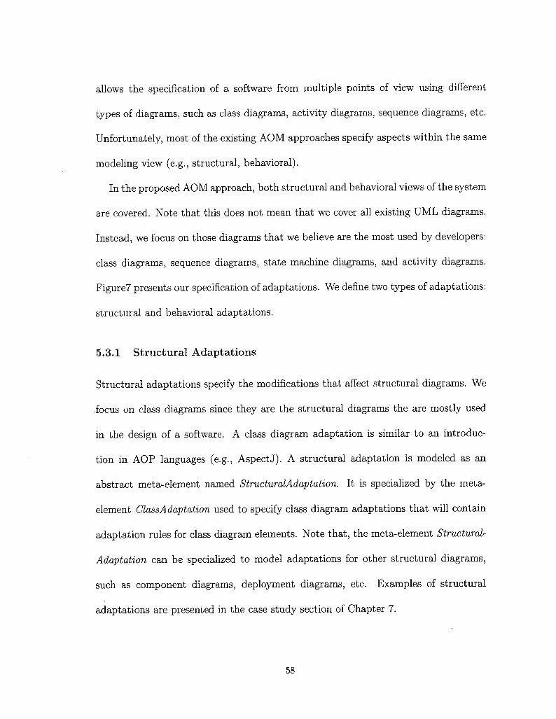
allows the specification of a software from multiple points of view using different
types of diagrams, such as class diagrams, activity diagrams, sequence diagrams, etc.
Unfortunately, most of the existing AOM approaches specify aspects within the same
modeling view (e.g., structural, behavioral).
In the proposed AOM approach, both structural and behavioral views of the system
are covered. Note that this does not mean that we cover all existing UML diagrams.
Instead, we focus on those diagrams that we believe are the most used by developers:
class diagrams, sequence diagrams, state machine diagrams, and activity diagrams.
Figure7 presents our specification of adaptations. We define two types of adaptations:
structural and behavioral adaptations.
5.3.1 Structural Adaptations
Structural adaptations specify the modifications that affect structural diagrams. We
focus on class diagrams since they are the structural diagrams the are mostly used
in the design of a software. A class diagram adaptation is similar to an introduc-
tion in AOP languages (e.g., AspectJ). A structural adaptation is modeled as an
abstract meta-element named StructuralAdaptation. It is specialized by the meta-
element ClassAdaptation used to specify class diagram adaptations that will contain
adaptation rules for class diagram elements. Note that, the meta-element Structural-
Adaptation can be specialized to model adaptations for other structural diagrams,
such as component diagrams, deployment diagrams, etc. Examples of structural
adaptations are presented in the case study section of Chapter 7.
58

5.3.2 Behavioral Adaptations
Behavioral adaptations specify the modifications that affect behavioral diagrams. In
our approach, we support the behavioral diagrams that are the most used for the
specification of a system behavior, mainly, state machine diagrams, sequence dia-
grams, and activity diagrams. A behavioral adaptation is similar to an advice in
AOP languages (e.g., AspectJ, AspectC++). A behavioral adaptation is modeled
as an abstract meta-element named BehavioralAdaptation. We specialize the meta-
element BehavioralAdaptation by three meta-elements: StateMachineAdaptation, Se-
quenceAdaptation, and ActivityAdaptation that are used to specify adaptations for
state machine diagrams, sequence diagrams, and activity diagrams respectively. As
for the meta-element StructuralAdaptation, the meta-element BehavioralAdaptation
can also be extended to model adaptations for other behavioral diagrams, such as
communication diagrams, interaction overview diagrams, etc. Examples of behav-
ioral adaptations are presented in the case study section of Chapter 7.
5.4 Aspect Adaptation Rules
An adaptation rule specifies the effect that an aspect performs on the base model
elements. We support two types of adaptation rules: adding a new element to the
base model and removing an existing element from the base model. Figure 8 depicts
our specified meta-model for adaptation rules.
59

«stereotype»Add
[Operation]NameiStringType:ElementTypePosition: PositionType
«stereotype»Pointcut
[Operation]TextExpression: StringOCLExpression: String
«stereotype»Remove
[Operation]
«enumeration»ElementType
I«enumeration»
PositionType
«enumeration»Structural ElementType
I
«enumeration»BehavioralElemenfType
BeforeAfterAround
«enumeration»ClassElementTypeClassPropertyOperationAssociationPackage
«enumeration»StateMachineElementTypeStateTransitionStateMachineRegion
«enumeration»SequenceElementTypeLifelineMessageInteractionInteractionUse
«enumeration»ActivityElementType
ActionActivityStructuredActivityNodeControlFlow
Figure 8: Meta-Language for Specifying Adaptation Rules
5.4.1 Adding a New Element
The addition of a new diagram element to the base model is modeled as a special kind
of operation stereotyped <^Add^>. We use the same specification for adding any kind
of UML element, either structural or behavioral. Three tagged values are attached
to the stereotype <g:Add^>:
• Name: The name of the element to be added to the base model.
• Type: The type of the element to be added to the base model. The values of
this tag are provided in the enumerations ClassElementType, StateMachineEle-
mentType, SequenceElementType, and ActivityElementType.
60

• Position: The position where the new element needs to be added. The values of
this tag are given by the enumeration PositionType. This tag is needed for some
elements (e.g., a message, an action) to state where exactly the new element
should be added (e.g., before/after a join point). For some other elements (e.g.,
a class, an operation), this tag is optional since these kinds of elements are always
added inside a join point.
The location where the new element should be added is specified by the meta-element
Pointent.
5.4.2 Removing an Element
The deletion of an existing element from the base model is modeled as a special kind
of operation stereotyped <^Remove^>. The set of elements that should be removed
are given by a pointcut expression specified by the meta-element Pointent. The same
specification is used for removing any kind of UML element, either structural or
behavioral. No tagged value is required for the specification of a Remove adaptation
rule; the pointcut specification is enough to select the elements to be removed.
The proposed profile for the specification of adaptations and their adaptation
rules is expressive enough to cover the common AOP adaptations. For example,
the profile allows to specify the introduction of a new class to an existing package,
a new attribute or an operation to an existing class, or a new association between
two existing classes. In addition, we can remove an existing class, an attribute or
an operation from an existing class, or an association between two existing classes.
As for behavioral modifications, the profile allows to specify the injection of any
61

UML behavior before, after, or around any behavioral UML element matched by
the concerned pointcut. For example, the profile allows to specify the addition of
an interaction fragment before/after a specific message in a sequence diagram, or an
action before/after a specific action in an activity diagram.
5.5 Pointcuts
A pointcut is an expression that allows the selection of a set of locations in the base
model (join points in AOP jargon) where adaptations should be performed. Themeta-element Pointcut is defined as stereotyped operation with two tagged values
attached to it:
• TexiExpression: The pointcut expression specified in our proposed textual point-
cut, language.
• OCLExpression: An OCL expression equivalent to the text expression, which
will be generated automatically during the weaving as we will see in Chapter 6.
The text expression pointcut language is a high-level, user-friendly language that
is easy to write and to understand. However, textual expressions cannot be used to
query UML elements and select the appropriate join points. Thus, in our framework,
we translate the textual pointcut expressions into OCL expressions to query UML
elements. By this approach, we benefit from the expressiveness of the OCL language
and at the same time we eliminate the overhead of writing such complex expressions
from the developers.
62

5.5.1 Pointcut Expression Language
Since the targeted join points are UML elements, pointcuts should be defined based
on designators that are specific to the UML language. To this end, we define in
our approach a pointcut language that provides UML-specific pointcut designators
needed to select UML join points. The proposed pointcut language covers all the
kinds of join points where the adaptations supported by our approach are performed.
Those primitive pointcut designators can be composed with different logical operators
AND, OR, and NOT to build other pointcuts.
The proposed pointcut language is expressive enough to designate the main UML
elements that are used in a software design. A UML element can be designated by
its name, type, properties, or by its relations to other UML elements. For example,
the pointcut language allows to designate a class that has a specific name and/or
has its visibility property set to public. In addition, our proposed pointcut language
provides high-level and user-friendly primitives that can be used intuitively by the
security expert to designate UML elements.
For instance, consider we want to write a pointcut expression to designate a class
named cl that is inside package pi, and contains an operation opl. Listing 1 is an
example of such expression:
Class(cl)&¿L·^ns?de-package(pl)kL·conta?ns-operat?on(opl) (1)
Moreover, if Ave want to designate all classes that contains either private attributes
63

or private operations. Listing 2 shows an example of such expression:
Class^^^contains-attribute^f-visibilityiprivate^l |
contains-operation(of-visibility{private))) (2)
The above examples show some features of our proposed language, such as the use
of V symbol to designate all elements of a particular type. Additionally, pointcut
expressions can be of two types, either simple expressions (Listing 1), or nested ex-
pressions (Listing 2).
5.6 Summary
In this chapter, we presented our approach for aspect specification in the design
level. We presented the proposed UML profile for aspect-oriented modeling. We
defined two types of adaptations: structural adaptations, and behavioral adaptations.
Additionally, we presented the supported adaptation rules and the proposed pointcut
language for designating UML elements.
64

Chapter 6
Weaving Aspects into UML Design
Models
Now that we have seen how we can specify UML aspects using our AOM profile,
in this chapter, we describe our approach for weaving aspect-oriented models that
conform to the AOM Profile presented in Chapter 5. This approach aims at weav-
ing aspects automatically and systematically into existing UML design models using
model transformation technology.
The main steps that are followed to implement the weaving capabilities are pre-
sented in Figure 9. The weaving process is organized into four steps: (1) aspect
specialization, where the application-independent aspect provided from the security
aspect library is going to be instantiated and produce an application-dependant as-
pect. (2) Pointcut translation, where each textual pointcut defined in the aspect is
translated into an equivalent OCL expression. The previous two steps can be consid-
ered a preliminary steps before the actual weaving begins. (3) Join point matching,
65

where the generated OCL expression is evaluated on the base model to identify the
locations where to perform the weaving. (4) QVT Transformation rules generation,
which takes as input the set of identified locations from the previous step along
with the set of adaptations specified in the aspect. Then, it selects the appropriate
transformation rules to be executed by the transformation engine on the base model.
Finally, the woven model is produced as output.
Aspect ^ySpecialization ^-^~
ApplicationIndependent
Aspect-?.
Adaptation
TextualH Pointcut
ApplicationSpecificAspectAdaptation
TextualPointcut
PointcutTranslation
QVT Transformation , ^_"^ Rules Generation ,
QVT TransformationRules
*¦ 1111
Transformation
Engine
Secure Woven Model
«=> Security AspectsLibrary /
ApplicationSpecificAspectAdaptation
OCL*i Pointcut
Join Points
Matching
Base Model
Figure 9: Aspects Weaving Overview
66

The remainder of this chapter is organized as follows. Sections 6.1 and 6.2 de-
scribes the two preliminary steps for aspects weaving: Aspect Specialization, and
Pointent Translation. Section 6.3 presents the details of the weaving process. Fi-
nally, Section 6.4 summarize this chapter.
6.1 Aspects Specialization
In order to achieve reusability of aspects, security experts define aspects as generic
solutions that can be applied to any design model. Thus, before being able to weave
the aspects into base model, they need to be specialized and instantiated with respect
to the developer base model.
During this step, the developer specializes the generic aspects by choosing the
elements of his/her model that are targeted by the security solutions. The pointcuts
specified by security experts are chosen to match specific points of the design where
security methods should be added. Since security solutions are provided as a library
of aspects, pointcuts are specified as generic patterns that should match all possible
join points that can be targeted by the security solutions.
In order to specialize the aspects, a weaving interface is provided. This interface
hides the complexity of the security solutions and only exposes the generic pointcuts
to the developers. From this weaving interface and based on his/her understanding of
the application, the developer has the possibility of mapping each generic element of
the aspect to its corresponding element (s) in the base model. After mapping all the
generic elements, the application-dependent aspect will be automatically generated.
67

We have to note here that this mapping operation has a one-to-many relationship.
In other words, one generic element in the pointcut expression can be mapped to
multiple elements in the base model. For example, consider the following pointcut
expression that aims at capturing all calls to a particular method:
message_call(sensitiveMethod)
In order to specialize the above expression, the developer maps the abstract element
sensitiveMethod to a corresponding operation(s) in his/her application (e.g., opl,
op2). This will result in an expanded pointcut expression where all the selectedelements are combined together with the logical operator OR.
message_call(opl) || message_call(op2)
6.2 Pointcut Parsing and OCL Generation
After generating the application-specific aspect, the next step is to translate the
textual pointcuts specified in the aspect to a language that can navigate the base
model and select the considered join points. In our approach, we chose to translate
the textual pointcut expressions into the standard OCL language [63] . This is due to
the high expressiveness of the OCL language, and its conformance with UML. OCL
is defined as part of the UML standard and is typically used to write constraints on
UML elements. However, since OCL 2.0 [67] it has been extended to include support
for query language.
Therefore, in our approach textual pointcuts are translated into OCL expressions,
which serve as predicates to select the considered join points. This translation is done
68

by producing a parser that is capable of parsing and translating any textual pointcut
expression, that conforms to its defined grammar, to its equivalent OCL expression.
Indeed, this process will be executed automatically and in a total transparent way
from the user.
6.3 Aspect Weaving Process
In this section, we present the details of the weaving process which include the design
and implementation of the model weaver tool. In our approach, the process of weaving
aspects into UML models is considered as a transformation process, where the base
model is being transformed into a new model that has been enhanced with some
new features defined by the aspect. When designing the weaving tool, the standard
language QVT is adopted. The proposed model weaver is implemented using well-
known standards, which makes it a portable solution as it is independent of any
specific UML tool.
Before going in details on the different transformation rules used to implement the
weaver, first we give a high-level description of the architecture of the weaving engine.
6.3.1 Weaving Engine General Architecture
The weaving engine is designed to manipulate structural and behavioral UML dia-
grams. It is capable of weaving different types of UML diagrams that are used to
model different views of the system.
Figure 10 presents the general architecture of our model weaver. It consists of
two main components: (1) Transformation module, (2) Join point matching module.
69

UMLBase
Model
AspectModel
Transformation Tool
ClassTransformation
Definition!
SequenceTransformation
I DefinitionQVT
Engine
ActivityTransformation
Definition
State MachineTransformation
Definition
WovenModel
Black-Box Mechanismfor Join Point Matching
Figure 10: General Architecture of the Weaving Engine
The transformation module is composed of four different transformation definitions
each of which corresponds to a particular type of UML diagram. On the other hand,
the join point matching module is defined by extending the QVT engine through the
QVT/Black-Box mechanism. In the sequel, each component is detailed.
Extending QVT using Black-Box Mechanism
Black-Box mechanism is an important feature of the QVT language. It facilitates
the integration of external programs expressed in other transformation languages
or programming languages in order to perform a given task that is un-realizable
by the QVT language. To this end, we define a join point matching module as
an extension to the QVT main functionalities. This new feature allows evaluating
pointcut expressions, specified in OCL, on UML base model elements and identifying
the appropriate join points that satisfy the given expression.
The join point matching algorithm takes an OCL expression as input along with
the base model elements and returns a set of join point elements that were evaluated
70

to true against the given expression. Algorithm 1 describes the pseudo code of our
join point matching algorithm.
Algorithm 1: Join Points MatchingInput: OCLExp, BaseM odelElementsOutput: JoinPointElem — set
query = CTea.teQuery(OCLExp);for all el in BaseM odelElements do
result = validate((3"uen/,eZ);if result is true then
JoinPointElem — set.update (el);end if
end forreturn JoinPointElem — set;
This process is repeated for each pointcut element specified in the aspect. However,
when dealing with big models with large set of model elements, this process may
become a significant overhead on the system. Therefore, some optimizations are
needed. Since each pointcut element belongs to a specific adaptation kind, e.g., State
Machine Adaptation, instead of passing all the base model elements to the join point
matching module some filtering can be performed such that, we only pass the base
model elements that conform to a given adaptation kind. For example, in case we have
a pointcut element defined in a state machine adaptation. The filtering mechanism
will select from the base model only those elements that conform to the state machine
model, and then pass them to the join point matching module. This optimization
increases the efficiency and the performance of the matching module.
Transformation Tool
The transformation tool consists of a set of transformation definitions. Each transfor-
mation definition targets a particular UML diagram, and contains a set of mapping
71

rules that define how each element in the corresponding diagram is transformed.
This architecture facilitates the extension of the transformation tool to support wider
range of UML diagrams, since new components can be easily plugged-in without going
through the hassle of modifying and altering the existing architecture.
Furthermore, since the definition of the specified mapping rules is based on the
UML meta-elements, this makes the transformations reusable with any UML model
and are not dependant on a particular specification or implementation.
When the transformation tool receives the base model as input, each transforma-
tion definition applies some filtering operations to select from the input model the set
of diagrams that corresponds to its type. Then, each transformation definition exe-
cutes the appropriate mapping rules using the underlying QVT engine and produces
the woven model as output.
6.3.2 Transformation Definitions
Transformation definitions describe how each element in the source model is trans-
formed in the target model. As mentioned previously, it consists of a set of mapping
rules that describe a certain behavior. For each aspect adaptation defined in Chap-
ter 5, we specify a corresponding transformation definition. By analogy, the aspect
adaptations are program source code and the transformation definitions are its execu-
tion semantics. In other words, it defines how and when each construct in the aspect
adaptation should produce a given behavior. In the following the four transformation
definitions are detailed.
72

• Class Transformation Definition: This is a structural transformation that is de-
signed to handle transformations of class diagrams. The main difference between
class transformation and the other transformations of behavioral diagrams is that
class diagrams are structural in nature; they are considered a static view. The
Class transformation definition iterates through the different adaptations in the
aspect and selects the adaptation that is stereotyped ClassAdaptation. For each
adaptation rule specified inside the class adaptation, an equivalent mapping rule
is applied.
• State Machine Transformation Definition: This is a behavioral transformation
that deals with state machine diagrams. State machine diagrams are used to
describe the behavior of a system by tracking the different states of an object in
that system and the events that may make an object go from one particular state
to the other. The state machine transformation definition selects the adaptation
in the aspect that is stereotyped StateM'achineAdaptation.
In our approach, when handling transformations of state machine diagrams, we
identify two kinds of pointcut designators: (1) state-based pointcut, and (2)
path-based pointcut. State-based pointcut designators are pointcuts that desig-
nate a set of states without any considerations of the transitions or events that
were triggered to reach them. On the other hand, path-based pointcut designa-
tors are those that designate states depending on the transition that triggered
them. For example, consider the state machine base model depicted in Figure
11 part (a), where we want to add a new state, State4, before state StateS when
73

triggered by transition TrI.
<
CJl J—>m
a) before Weaving
$J Statel J —^J State4 ]
1 ±.f State2 J ^i State3 J ^H)
b) after Weaving
Figure 11: Weaving Example for Path-Based Join Point
State(s3) && !ncoming(trt) (textual pointcut)
self.ocllsTypeOf(State) and self.name='s3' andself.incoming-vexists(t:Transition | t.name='tr1'); (OCL pointcut)
Figure 12: Pointcut Expression Example
To do so, the pointcut expression presented in Figure 12 need to be specified.
During the join point matching process, the generate OCL expression is evaluated
on the base model elements and will return the element StateS as the identified
join point. Then, the weaving process will add the new state State4 before the
identified join point. However, if the state StateS has more than one incoming
transition, which is the case in our example, the weaver will add the new state
State4 before all incoming transitions, which is not what we aim for. Thus, to
solve this problem, the OCL expression is used not only as a query language
to identify the join points during the matching process, but is also used to put
further constraints on the identified join points during the weaving. To this end,
74

our identified join point is state StateS under the constraint of being triggered
by transition TrI. The result of the weaving is shown in part (b) of Figure 11.
In our approach, join points in state machine diagrams can be either States,
or Transitions. Furthermore, as mentioned earlier, three weaving operations:
before, after, and around are supported.
Weaving Before Adaptation:
This operation requires not only identifying the join point where the adaptation
need to be performed, but also its direct predecessor should be identified. Al-
gorithm 2 summarizes the steps needed to add a new node before an identified
join point. In the algorithm, the two types of join points: State and Transition
are considered as well as the two types of pointcuts, state-based and path-based
pointcuts. The algorithm takes as input the set of join point elements, the ocl
expression, the new node to add, and the base model, and returns the woven
model as output, where the new node has been added before each of the identified
join points.
Weaving After Adaptation:
In contrast with before weaving, weaving after adaptations into state machine
diagrams require identifying the direct successors of an identified join point.
Algorithm 3 summarizes the steps needed to add new node after an identified
join point. The algorithm takes as input the set of join point elements, the ocl
expression, the new node to add, and the base model, and returns the woven
model as output, where the new node has been added after each of the identified
75

Algorithm 2: State Machine: Weaving Before AdaptationInput: JoinPointElem — set, OCLExp, newNode, BaseModel
edgeSet: Edge-set;for nextJoinPoint in JoinPointElem — set do
if nextJoinPoint is of type STATE thenif isPathBased(OCLExp) then
oclConstraint = extractConstrain^OCL-Ezp);edgeSet = getInComingEdge(ne:riJoinPoint, oclConstraint);
elseedgeSet = getInComingEdges(nexiJoinPoint);
end iffor all edge in edgeSet do
edge.setTarget(newNode);end forBaseModel = CreateEdge(neu>Node, nextJoinPoint);
else if nextJoinPoint is of type TRANSITION thentemp = getSource(nextJoinPoint);nextJoinPoint.setSo\irce(newNode);BaseModel = CreateEdge(ie?np, newNode);
end ifend for
join points. Similar to before weaving, we consider both kinds of join points and
pointcuts.
Weaving Around Adaptation:
Around adaptations are injected in place of the join point they operate over,
rather than before or after. Additionally, inspired by AspectJ approach [47],
within the behavior of the around adaptation the original join point can be in-
voked with a special element named proceed. Indeed, the type of the join point
element must be equivalent to the type of proceed element in the around adap-
tation. Around adaptations can have one of two effects: (1) Replace, in case
the proceed element is not used in the adaptation behavior. (2) In case the pro-
ceed element exist in the behavior to be injected, then all elements that appear
before the proceed element are injected before the join point, and similarly all
76

Algorithm 3: State Machine: Weaving After AdaptationInput: JoinPointElem, — set, OCLExp, newNode, BaseModel
edgeSet: Edge-set;for nextJoinPoint in JoinPointElem — set do
if nextJoinPoint is of type STATE thenif isPathBased(OCLi;xp) then
oclConstraint = extractConstraint(OCL.Ea;p);edgeSet = getOutGoingEdge(ne;riJoinPoint, oclConstraint);
elseedgeSet = getOutGoingEdges(nea;iJoinPoint);
end iffor all edge in edgeSet do
eiá<7e.setSource(neu;./Voc¡e) ;end forBaseModel = CreateEdge(nea;iJoinPoint, newNode);
elseif nextJoinPoint is of type TRANSITION then
temp = getTarget(nexiJoinPoint);nextJoinPoint.setTarget(neuiNode);BaseModel — CieateEdge(newNode, temp);
end ifend if
end for
elements appearing after the proceed element are injected after the join point.
Algorithm 4 represents the algorithm used to weave around adaptations in state
machine diagrams. The algorithm takes as input the set of join point elements,
the ocl expression, the new state machine element to add, and the base model.
The algorithm then places the new state machine element in place of the current
join point and checks whether the new state machine element contains a "pro-
ceed" element or not. If the proceed element exists, then it will be identified
and replaced with the current join point. Otherwise, the current join point is
deleted.
• Activity Transformation Definition: This is a behavioral transformation that
aims at transforming activity diagrams. Since activity diagrams aim at modeling
the step-by-step flow of an operation or a business process, when weaving a new
77

Algorithm 4: State Machine: Weaving Around AdaptationInput: JoinPointElem - set, OCLExp, newSMElem, BaseModel
for nextJoinPoint in JoinPointElem — set doreplace(nea:iJoinPoint, newSMElem);if isProceeá(newSMElem) then
proceedElement = findProceed^euiS'M.E'Zem);iep\a.ce(j>roceedElement, nextJoinPoint) ;áe\ete(proceedElement) ;
elsedelete(nextJoinPoint) ;
end ifend for
Procedure replace:Input: oldElement, newElement
edgeSet: Edge-set;edgeSet = mCommgEdges(oldElement);for all edge in edgeSet do
edge, setTarget (neu>Element) ;end foredgeSet = outGomgEdges(oldElement);for all edge in edgeSet do
ed(?e.setSource(neu;¿5Zeme7)¿) ;end for
behavior into such flow ordering must be taken into consideration. In addition,
operations such as concurrency, loop, and choice can be modeled in activity
diagrams. Therefore, such operations need to be captured as well. The Activity
transformation definition selects the adaptation in the aspect that is stereotyped
ActivityAdaptation. In our approach, join points in an activity diagram can
be either a node, or an edge. The node can be an activity action or control
node (fork, join, decision, merge). Similarly, the edge may be a control flow
or an object flow. Weaving operations in activity diagrams are very similar to
state machine, as both diagrams are constructed from nodes and edges. In the
following, we describe each weaving operation in activity diagrams.
Weaving Before Adaptation:
78

Weaving before adaptation in activity diagrams requires identifying the join
point type, whether it is an action, flow, or a control node, and its direct prede-
cessor. In case the join point is an action, all incoming flows are redirected to
the new node. As such, a new flow is created between the new node and the join
point. However, if the join point is a control node of type join or merge, where
there are two separate incoming flows, then the new node is duplicated for each
flow. Thus, each incoming flow going to the join or merge nodes is redirected
to a new node and two new flows are created between the new nodes and the
join point (See Figure 13). The algorithm used to weave before adaptations in
activity diagrams is shown in Algorithm 5. The algorithm takes as input the set
of join point elements, the new node to add, and the base model, and returns the
woven model as output, with the new node added before each of the identified
join points.
.^9?&
Í Action 1 J-
ÍAct¡on2 J- -H->
Í Action 1 J—>f newActionl- ^l
Í Action2 J—5»f newAction V -^
^oo*
(a) before weaving (b) after weaving
Figure 13: Example of JOIN Element as Join Point
Weaving After Adaptation:
In case the join point is an action, all outgoing flows are redirected to the new
node. Accordingly, a new flow is created between the join point and the new
node. However, if the join point is a control node of type fork or decision where
79

Algorithm 5: Activity: Weaving Before AdaptationInput: JoinPointElem — set, newNode, BaseModel
edgeSet: ActivityEdge-set;for nextJoinPoint in JoinPointElem — set do
if nextJoinPoint is of type ActivityNode thenedgeSet = getlnComingEdges(nextJoinPoint);if nextJoinPoint is of type JoinNode or MergeNode then
for all edge in edgeSet docopy newNode;edge.setTa,Tget(newNode);BaseModel = CreateEdge(neu!./Voa!e, nextJoinPoint);
end forelse
for all edge in edgeSet doedge.set'Ta.iget(newNode) ;
end forBaseModel = CreateEdge(neu;./Vode, nextJoinPoint);
end ifelse if nextJoinPoint is of type ActivityEdge then
temp = getSource(nexiJoinPoint);nextJoinPoint.setSomce(newNode);BaseModel ¦— CreateEdge(iemp, newNode);
end ifend for
there are two separate flows, then a new node is created for each flow. Thus,
each outgoing flow going out from the fork or decision node, is redirected to
the new node, and two new flows are created between the new nodes and the
original join point successors (See Figure 14). The algorithm used to weave after
adaptations in activity diagrams is shown in Algorithm 6. The algorithm takes
as input the set of join point elements, the new node to add, and the base model,
and returns the woven model as output, with the new node added after each of
the identified join points.
Weaving Around Adaptation:
The operation of weaving around adaptation in activity diagrams is similar to
the one described previously for state machine diagrams.
80

' Jolnp,oint-
-N
-5/Action il
-$/ActJon2j
~Joinp,oint-
=>f newAction J >( Action 1 j
=/ newAction J 3>f Action2 J
(a) before weaving (b) after weaving
Figure 14: Example of FORK Element as Join Point
Algorithm 6: Activity: Weaving After AdaptationInput: JoinPointElem — set, newNode, BaseModel
edgeSet: ActivityEdge-set;for nextJoinPoint in JoinPointElem — set do
if nextJoinPoint is of type ActivityNode thenedgeSet = getOutgoingEdges(ne:riJoinPoint);if nextJoinPoint is of type ForkNode or DecisionNode then
for all edge in edgeSet docopy newNode;edge.setSource(newNode) ;BaseModel = CreateEdge(nea;iJoinPoint, newNode);
end forelse
for all edge in edgeSet doed(?e.setSource(neu;/V'ode) ;
end forBaseModel = CreateEdge(nexiJoinPoint, newNode);
end ifelse if nextJoinPoint is of type ActivityEdge then
temp = getTa,rget(nextJoinPoint);nextJoinPoint.setTasget(newNode);BaseModel = CreateEdge (new./Vocfe, temp);
end ifend for
Sequence Transformation Definition: This transformation definition is applied on
adaptations in the aspect with stereotype SequenceAdaptation. It is a behavioral
transformation that aims at transforming interaction diagrams. An interaction
is used to describe how different entities in a system interact with each other
and in what order. Ordering in interaction diagrams is realized by a trace of
event occurrences, where each event is specified by a unit called occurrence spec-
ification. Occurrence specifications are ordered along a lifeline where each unit
81

references the occurrence of a specific event [64] (See Figure 15).
LifeLinel LifeLine2
? ml ?
Send event_1 (J) ~ ?Ç Receive event_1Send event_2 (J) ^Q Receive event_2
Figure 15: Send/Recieve Events in Sequence Diagrams
In our approach, we consider sequence diagram messages as join points, where a
new behavior may be added before, after, or around the occurrence of send/re-
cieve message events.
Weaving Before Adaptation:
As mentioned previously, order in sequence diagram interactions is represented
by a trace of events. Here we are interested particularly in the send and receive
events of the exchanged messages. Weaving an adaptation before an identified
join point message, means that the adaptation should be performed before the
"send event" of the join point message is fired. This requires identifying the
sending event associated with the join point message from the list of interaction
trace of events. Algorithm 7 summarizes the steps needed to weave a new element
before an identified join point message. The algorithm takes as input the set of
join point messages, the new element to add, and the base model, and returns
the woven model as output, where the new node has been added before each of
the identified join points. The algorithm extracts the trace of events from the
base model and identifies the send event of the join point message. Then, it adds
82

the new element send and receive events before the identified send event of the
join point message.
Algorithm 7: Sequence: Weaving Before AdaptationInput: JoinPointMessage — set, newElement, BaseModel
traceEvent: Event-list;traceEvent = getEventTrace(-BaseMoaei);for all nextJoinPointMessage in JoinPointMessage — set do
sndEvent = getSendEvent(nextJoinPointMessage);indx = traceEvent.get'mdexOî(sndEvent);newSendEvent = CreateSendEvent (newElement);newReceiveEvent = CreateReceiveEvent(neu;-EZemeni);if indx = 1 then
traceEvent = traceEvent.pTepena(newReceiveEvent);traceEvent = traceEvent.piepend(newSendEvent);
elsetraceEvent, insertAt (indx,newSendEvent);traceEvent.msertAt(indx + !,newReceiveEvent);
end ifend for
Weaving After Adaptation:
In contrast with weaving of before adaptations, here we are interested in the
receive event of the join point message. In this case, the send/recieve events of
the new element are inserted after the receive event of the join point message (See
Algorithm 8). The algorithm takes as input the set of join point messages, the
new element to add, and the base model, and returns the woven model as output,
where the new node has been added after each of the identified join points. The
algorithm extracts the trace of events from the base model and identifies the
receive event of the join point message. Then, it adds the new element send and
receive events after the identified receive event of the join point message.
Weaving Around Adaptation:
Weaving around adaptation in sequence diagrams is simply a replace operation.
83

Algorithm 8: Sequence: Weaving After AdaptationInput: JoinPointMessage — set, newElement, BaseModel
traceEvent: Event-list;traceEvent = getEventTrace(ßaseMode/);for all nextJoinPointMessage in JoinPointMessage — set do
rcvEvent = getReceiveEvent (nextJoinPointMessage);indx = traceEvent.get'mdexOî(rcvEvent);newSendEvent = CreateSendEvent(newSZemeni);newReceiveEvent = CreateReceiveEven^newiJZemeni);if indx — traceEvent.sizeQ then
traceEvent = traceEvent.&ppend(newReceiveEvent);traceEvent = traceEvent.append(newSendEvent);
elsetraceEvent.msertAt(indx+l,newSendEvent);traceEvent.insertAt(indx+2,newReceiveEvent);
end ifend for
Both the send and receive events of the join point message are replaced with the
new element. Algorithm 9 present the algorithm for weaving around adaptation
in sequence diagrams. The algorithm takes as input a set of join point elements,
the new element to add, and the base model, and returns the woven model as
output.
The use of the around operation with proceed facilitates the specification of differ-
ent crosscutting concerns that are not realized by other operations (i.e., before and
after). For instance, crosscutting concerns that need to be weaved in parallel with
some join points can be specified using the around with proceed operation.
For example, consider the traditional scenario of placing an order depicted in
Figure 16 part (a), where we want to add a new action that notifies the user while
his/her order is being shipped. To do so, an around adaptation, presented in Figure 16
part (b), is needed. In order to weave the around adaptation we replace the proceed
element in the around behavior with the identified join point. After that, the entire
84
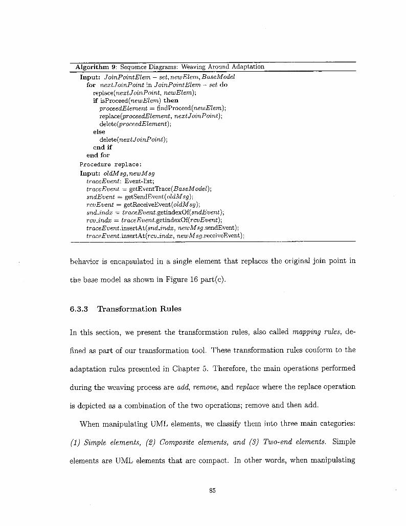
Algorithm 9: Sequence Diagrams: Weaving Around AdaptationInput: JoinPointElem — set, newElem, BaseModel
for nextJoinPoint in JoinPointElem — set dorepl&ce(nextJoinPoint, newElem);if isProceed(newElem) then
proceedElement = findProceed(new-BZem);rep\a,ce(proceedElement, nextJoinPoint) ;delete (proceedElement) ;
elsede\ete(nextJoinPoint);
end ifend for
Procedure replace:Input: oldMsg, newMsg
traceEvent: Event-list;traceEvent = getEventTrace(BaseModel);sndEvent = getSendEvent(oldMsg);rcvEvent = getReceiveEvent (oZdMsg);snd-indx = traceEvent.getindexOf(snaEweni);rcvJndx = traceEvent.getmdexOi(rcvEvent);traceEvent.insertAt(snd-indx, newMsg.sendEvent) ;traceEvent.inseitA.t(rcvJ.ndx, newMsg.receiveEvent) ;
behavior is encapsulated in a single element that replaces the original join point in
the base model as shown in Figure 16 part(c).
6.3.3 Transformation Rules
In this section, we present the transformation rules, also called mapping rules, de-
fined as part of our transformation tool. These transformation rules conform to the
adaptation rules presented in Chapter 5. Therefore, the main operations performed
during the weaving process are add, remove, and replace where the replace operation
is depicted as a combination of the two operations; remove and then add.
When manipulating UML elements, we classify them into three main categories:
(1) Simple elements, (2) Composite elements, and (3) Two-end elements. Simpleelements are UML elements that are compact. In other words, when manipulating
85

a) Base Model JoinpointJL
0^/p|ace Order\>nvlake Payment^^/shipmentY^/Delivery }>?
b) Around Adaptation
I—^f proceed J—>W ^U-^NotifyUserVs»
» ?·> ·¦ j ¦ /* «structured»c) Woven Model / shipandNotifv
^^Place OrderV^Make Payment)-^ ^ —^Shipment)—> ^^ —j/DeliveryV^^V —s/NotlfyUserY-S» J
Figure 16: Example: Placing Order Activity Diagram.
them you deal with single atomic element. Examples of simple elements are opera-
tions, simple states, actions, and properties. Composite elements are elements that
are composed of other elements, or contain references to other UML element. For
example, interaction use in sequence diagrams is considered a composite element as
it is used to reference other interactions. Other examples of composite elements are
classes, submachine states, and structured activity nodes. Two-end elements are el-
ements that connect two UML elements together, such as associations, transitions,
massages, and control/object flows. Table 3 presents a classification of the supported
elements according to their categories.
Before describing the set of defined mapping rules, first it is necessary to introduce
the main operators defined by the QVT language.
• "Map" Operator: The map operator is used to apply an operation, or what is
called mapping rule, on a single element or a set of elements.
• "—» " Operator: The "—>" operator is used to iterate on collections of elements.
When combined with the map operator, it facilitates the access to each element
in the collection in order to apply the mapping rule to them.
86

Table 3: Classification of the Supported UML ElementsUML Diagram UML Element Category Type
ClassDiagram
PackageClassOperationPropertyAssociation
CompositeCompositeSimpleSimpleTwo-end
StateMachineDiagram
State MachineStateSubmachine StateTransitionRegion
CompositeSimpleCompositeTwo-endComposite
SequenceDiagram
InteractionInteraction UseLifelineMessage
CompositeCompositeSimpleTwo-end
ActivityDiagram
ActivityActionStructured Activity NodeControl Flow
Object Flow
CompositeSimpleCompositeTwo-endTwo-end
ß " · " Operntor: The " · " operator can be applied to single elements to access
their properties or operations. When combined with the map operator, it applies
the mapping rule to that element.
For instance, Listing 3 shows how to apply a mapping rule addAttribute, which
adds an attribute attr to a given set of Class elements Set{ classElem} , using the map
and —»· operators.
Set{classElem} —» map addAttribute(attr); (3)
The —> operator iterates through classElem set and for each element in that set, it
applies the mapping rule addAttribute to it. The result of this expression is a new
set of classes where each class has the new attribute attr added to it.
87

In the sequel, the main mapping rules add and remove with all their correspond-
ing sub rules are detailed.
• Rule 1: Add Mapping Rule
Add mapping rule is executed on all adaptation rules in the aspect that are
stereotyped with the stereotype -C add^>. It is important to mention here that
the order of adaptation rules, as specified by the aspect designer, in each adap-
tation of the aspect is preserved during the weaving.
OrderedSet{addAdaptationRules} ->¦ map addMappingRuleO;
Figure 17: Add Mapping Rule
Figure 17 illustrates how the "add mapping" rule is applied on each element of
the input ordered set of "add adaptation" rules. For each adaptation rule in this
set, the values of its properties or tagged values are read to further determine the
next mapping rule to be invoked. Mainly, the tagged value type, which specifies
the type of the UML element to add, determines the appropriate add subrule
to be invoked. Additionally, the tagged value name identifies the name of the
new element to add. The tagged value position of the "add adaptation" rule
references the position where to add the new element in contrast with other
existing elements in the base model (i.e., before, after, around). Finally, the
value of the tagged value pointent is passed to the join point matching module
to identify the set of join points in the base model where the new element need
to be added (See Figure 18).
After identifying the set of join points and the type of element that we need to
88

Set{joinPo¡ntElements} := Set{baseModelElements}->jo¡nPointMatching(OCLExpression);
Figure 18: Join Point Matching
add. Depending on the category of that element (See Table 3) the appropriate
subrule is applied to each element in the join point elements set.
- Rule 1.1 Add Simple Element (elementName, position)
This mapping rule is applied to each join point in the set of elements that
has been previously identified. It takes two parameters: name: the name
of the simple element to add, and position: the position where to add the
element. Position can take one of four values: Before, After, Around, or the
default value Inside. Depending on the value of position, the newly created
element will be placed in the base model. This mapping rule creates the
appropriate meta-element object and sets its name to the value passed in
the parameter elementName (See Figure 19).
object simple-meta-element { name:=elementName };
Figure 19: Add Simple Element
- Rule 1.2 Add Composite Element (elementName, position)
Add composite element mapping behaves in a similar way to the previous
rule. However, it extends the behavior of the previous rule by adding a check
for the elements that the new element should compose. For example, in case
of interaction use element, a reference to the composed interaction behavior
needs to be identified. To this end, the mapping rule iterates through the
89

aspect's enclosed elements and selects the behavior that matches the name
of the element to add. Finally, the selected element is copied to the base
model and the composite element is created (See Figure 20).behaviorElement := Set{aspectElements}->Select(el | el.name = elementName);
object composite-meta-element { name:= elementName; refersTo := behaviorElement;};
Figure 20: Add Composite Element
- Rule 1.3 Add Two-End Element (elementName, position, source-
Exp, targetExp)
Similarly, this mapping rule extends the behavior of the add simple element
rule. Dealing with two-end elements is different to any simple element,
because it is necessary to specify the source and the target for that element.
Therefore, when specifying an adaptation rule for any two-end element, two
additional pointcuts are needed: one to select the source, and one for the
target elements. These two pointcuts are specified as parameters for the
add adaptation. It is important to note that the order here is crucial. The
first parameter represents the source pointcut, while the second parameter
represents the target pointcut (See Figure 21).
Set{sourceElem}:=Set{baseModelElements} —»-joinPointMatching(sourceExp);
SetftargetElem} := Set{baseModelElements} —»-joinPointMatching(targetExp);
object two-end-meta-element { name:=elementName; source:=sourceElem;target:=targetElem; }
Figure 21: Add Two-End Element
90

• Rule 2: Remove Mapping Rule
Remove mapping rule is applied to each adaptation rule in the aspect stereotyped
with -Cremore» stereotype. It reads the value of the tagged value pointcut and
passes it to the join point matching module in order to identify the set of elements
that need to be removed. Unlike the additive rules, the type of element to remove
is not important. Thus, there is only one general rule to remove any type of UML
element. Each identified join point is removed using the destroy() method (See
Figure 22).
Set{elementsToRemove}:=Set{baseModelElement}->-joinPointMatching(pointcut);
Set{elementsToRemove}-»-destroy();
Figure 22: Remove Element
Indeed, the remove operation is very sensitive and must be dealt with cautiously,
otherwise it may result in an incorrect UML woven model. For instance, remov-
ing a state in state machine diagram without reconnecting its predecessor with its
successor will result in two disconnected state machines. Therefore, the assump-
tion here is that, when designing an aspect, in case of any remove operation,
it must be followed by an add operation that will either replace the removed
element or correct any of the arising issues.
• Rule 3: Tagging Mapping Rule
Tagging mapping rules are used to trace the performed modifications on UML
91

base models. Each element that has been added or modified by the transforma-
tion needs to be easily identified in the woven model. To do so, the tagging map-
ping rule tags each element affected by the transformation by applying a special
keyword to it. These keywords appear on the generated woven model elements
between '<' and '>' as follows: <C AddedElement> or <ModifiedElement».
Table 4 summarizes all the supported mapping rules.
6.4 Summary
In this chapter, we presented our approach for automatic integration of aspects into
UML design models. We detailed the general steps of the proposed weaving approach.
Additionally, we presented the different weaving algorithms used with respect to the
supported UML diagrams. We explained our approach for join point matching and
actual weaving. The different transformation definitions and mapping rules used to
perform the weaving were also detailed.
92

Table 4: List of All Mapping RulesTransformation Definition Mapping
RuleSubRule
Add
ClassTransformationDefinition Remove
Tag
addClassaddAttributeaddOperationaddPackageaddAssociationremoveClassremoveOperationremoveAssociationremovePropertyremovePackagetagElement
Add
StateMachineTransformationDefinition Remove
Tag
addStateaddTransitionaddSubMachineStateaddStateMachineaddRegionremoveStateremoveTransitionremoveSubMachineStateremoveStateMachineremoveRegiontagElement
Add
ActivityTransformationDefinition Remove
Tag
addActionaddControlFlowaddObjectFlowaddStructuredActivity NodeaddActivityremoveActionremoveControlFlowremoveObjectFlowremoveStructured ActivityNoderemoveActivitytagElement
SequenceTransformationDefinition
Add
Remove
Tag
addMessageaddlnteractionUseaddlnteractionaddLifelineremoveMessageremovelnteractionUseremovelnteractionremoveLifelinetagElement
93
Chapter 7
Aspects Weaving Plug-in
This chapter presents the tool design and implementation details to support automatic
integration of security aspects into UML design models. Our tool is developed as a
plug-in to IBM Rational Software Architect/Modeler (RSA/RSM) [39,40]. RSA is
an advanced model-driven development tool. It leverages model-driven development
with UML for creating well-architected applications and services [39] . Moreover, since
RSA is built on top of Eclipse [82] , our tool can be easily integrated with any IDE
that is based on the Eclipse platform. This chapter is organized as follows. Section
7.1 presents an overview of the MOBS2 framework, a research project in which this
research work has been part of. Section 7.2 illustrates the different components and
technologies used to design and implement the Aspect Weaver plug-in. Section 7.3
presents a case study to show the feasibility of our approach. Finally, we summarize
this chapter in Section 7.4.
94

7.1 MOBS2 Framework
The research work done in this thesis is conducted as part of the research initiative
supported by Ericsson Canada Software Research. The aim of this research collabo-
ration is to develop a framework for Model-Based Engineering of Secure Software and
Systems (MOBS2). The framework starts from verification and validation of security
properties on UML design models with the objective of detecting security vulnerabil-
ities. Once these vulnerabilities are identified, the system goes to the second phase,
where an appropriate security solution specified as aspect is automatically integrated
with the system design in order to harden it. Figure 23 shows a screen shot of RSM
tool with MOBS2 plug-ins being deployed.
¿tie SM flautate Stateti ?(f?t AqatcaMeavfeg Se«iwDest[|R Run Ssinpfe fcte&Srç Winfow Helpj - , . 1 ta od »y » ^l ** * ^ s e»íi»-íj»-lí'·'* -í" resa
i -o
? ?
i ? t¡E¡.1 V &¦
ftOMProtilePJugin o¦>BSfrtXäJlwiei fisg« >-tí.ciisteJemeñtsC«teís
i.ciiîe.mo£iè!Trartîfcr:
; s> m
DesignWtflvmgDraftPtojeetemf-sampieemfProjMessaging :¡MMS I'MMSjiwfües jiagifiJis;;modripro)«t>i>dchedcêf jíügí»,siií!·<*&rt«ekeroli!
OpenÍMS 'iojg.edípse.-rn2m.qvtorv; .aTg.edJpie.m2m.te£ts,q';PfagtñfircjíctTrareif ~ptofrlepluçprtiest= Profiles ifûçlii-irici :;¦
RBACtapecïremoveNjavs
. ' S*cuiity^As(»*ct»^ Lîbca :
E P.típerties S\^T«iE|^,-Coie^!.^Boeím¿*tí;
Properties ore rtol· available.
Figure 23: M0BS2 Plug-in Integrated with RSM
95

7.2 Aspects Weaving Plug-in
The aspects weaving plug-in can be broken down into different components, where
each of which performs a given task in the different weaving steps. Figure 24 presents
the different components that make up the weaving plug-in.
Security PropertyEditor(Java)
Aspects WeavingPlug-in
AspectSpecialization Aspect Parser
(Java)
1Weaving Process
WeavingInterface
(Java)
Pointcut Parser(CUP parser)
Join PointMatching
(Java)
TransformationRules
(QVTO)
Figure 24: Aspects Weaving Plug-in
1. Security Property Editor: This is the first step towards hardening an application
design. The developer uses the security property editor to select the model that
he/she wants to harden, and to chose a specific security aspect from the security
aspects library to be applied on that model. Figure 25 shows a screen shot of
the Security Property Editor.
2. Aspect Specialization: This step specializes the generic security aspect that was
chosen in the previous step to the target application. The result of this step will
be the automatic generation of an application-specific aspect. The specialization
process is done through the use of the weaving interface. Weaving Interface is a
GUI that facilitates the mapping of generic elements in the aspect to elements in
96

Elementi
ESsertkeprevWer ?a*«:
1;8«?»??
gl AjAorfation§ Mr Seetange
iß üsputVaiidali««
g| Mon Repudiation
ffl RSaCBl SeaseyLÉ
¦teissÄBtwJ iaiffiÉsfa! -'i
Figure 25: Security Property Editor
the target application. The mapping process is one-to-many. In other words, de-
velopers can map a single abstract element to a set of elements in the application
model.
3. Aspect Parser: This component is responsible of parsing the selected aspect,
and identifying the different kinds of adaptations contained in the aspect. For
each adaptation kind, it will invoke the equivalent transformation definition.
Furthermore, before executing the transformations, the pointcut expressions are
translated to OCL expressions. This is done by another component, Point-
cut Parser. The pointcut parser is generated using CUP parser generator for
Java [16]. CUP parser takes the language grammar and a scanner as input, and
generates a Java parser as output.
4. Weaving Process: This step is responsible of performing the actual weaving of
the aspect and the base model. It includes two main components: Join Points
Matching Module and Transformation Rules. The join points matching module
is responsible of querying the base model using the generated OCL expressions,
97

and returning the set of elements that were evaluated to true.
Transformation rules are then executed on the identified join points. These rules
are implemented using the Eclipse M2M QVT Operational plug-in [44] on top
of the Rational Software Architect tool [39].
7.3 Case Study: Service Provider Application
To illustrate the feasibility of our approach, in this section, we show how to automati-
cally integrate different security aspects into a Service Provider Application. Figure 26
presents the class diagram of the application. In this scenario, clients can login to
a database of subscribers and services through the interface provision. The Client
class represent different types of users with different privileges. Provision interface is
implemented by the classes SubscriberManager and ServiceManager for manipulating
Subscribers and Services respectively.
Service Provider Application
Client
clientlDsessionlD
loginOlogoutO
«interface»Provision,
? add()updateOdeleteOsearchO
tei— -
fc
SubscriberManager
addOupdateOdelete»searchO
Resource
resourcelDResourceDB
getlnstanceOexecuteCommandOgetConfirmationQ
ServiceManager
addoupdateOdeleteOsearchO
ServiceserviceDetails
SubscribersubscriberProfile
Figure 26: Service Provider Application Class Diagram
Before clients can access a particular service, they must login first by providing
98

username and password as their credentials. The login process is modeled as an
activity diagram, which is presented in Figure 27
^i getPassword Jauthenticate
^f gelUserName J
f loggedln j
Figure 27: Activity Diagram Illustrating the Login Process
Furthermore, when a user issues a request to delete a subscriber, the method delete
of the SubscriberManager class is called. This method executes the command to delete
the subscriber from the database. Afterwards, the database destroys the respective
instance of the subscriber by sending the destroy message. To guarantee the deletion
of the subscriber instance, the SubscriberManager asks for the confirmation and sends
the results to the Client. Figure 28 represents a sequence diagram explaining the
entire interaction.
In the following sections, we present our approach by adding two security aspects
to the service provider application: Role-Based Access Control Aspect, and Input
Validation Aspect.
99

sdDeleteSubcriber.7iClient :SubscriberManaaer :ResQurceDB !Subscriber
deleteOexecuteCommand()
getConfirmationOdestroy
-Xconfirmation
deleteComplete ¡?<i
Figure 28: Sequence Diagram illustrating the Delete Subscriber Method
7.3.1 Role-Based Access Control (RBAC) Aspect
In this section, we will see how we can use our approach to enforce access control
mechanisms on the service provider application. The access control that is used is
the RBAC model. Before illustrating the design of the RBAC aspect, first we give
a short background on the different RBAC models. RBAC is organized into four
models [76]:
1. Flat RBAC: It is the core model that embodies the essential concepts of RBAC:
users, roles, and permissions. It specifies the assignment of users to roles and
the assignment of permissions to roles.
2. Hierarchical RBAC: It extends the flat RBAC by supporting role hierarchies.
3. Constrained RBAC: It extends the hierarchical RBAC by supporting separation
of duty constraints.
4. Symmetric RBAC: It extends the constrained RBAC by adding the ability to
perform permission-role review.
100
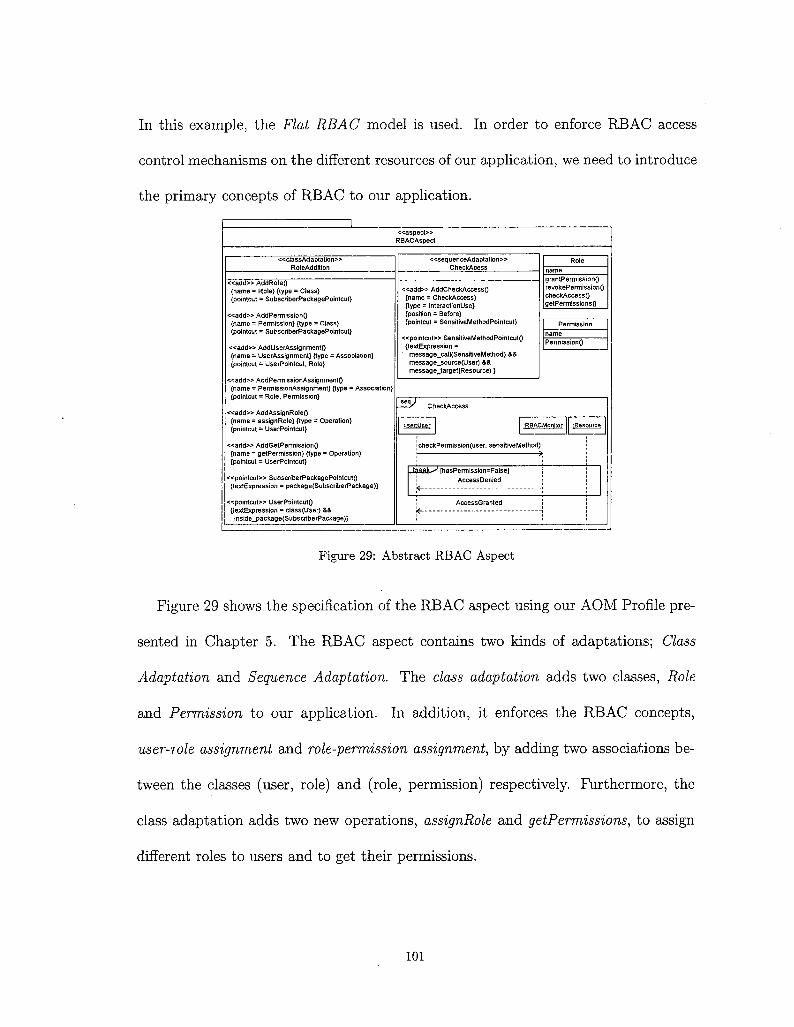
In this example, the Flat RBAC model is used. In order to enforce RBAC access
control mechanisms on the different resources of our application, we need to introduce
the primary concepts of RBAC to our application.
«aspect»R BACAspect
<classAd a ptation»RoleAddition
«add» Add RoIeO{name = Role} {type = Class)[pointcut = SubscriberPackagePointcut}
«add» AddPermissionO{name = Permission} {type = Class}(pointcut = SubscriberPackagePointcut}
«add» AddUserAssignmentO{name = UserAssignment} {type = Association}{pointcut = UserPointcut. Role}
«add» AddPermissionAssignmentO{name = PermissionAssignment} {type = Association}{pointcut = Role. Permission}
«add» AddAssignRoleO{name = assignRole} {type = Operation}{pointcut = UserPointcut}
«add» AddGetPermissionO{name = getPermission} {type = Operation}{pointcut = UserPointcut}
«pointcut» SubscriberPackagePointcutO{textExpression = package(SubscriberPackage)}
«pointcut» UserPointcutO{iextExpression = class(User) &&
inside_package(SubscriberPackage)}
«sequen ceAda ptation»CheckAcess
«add» AddCheckAccessO{name = CheckAccess}{type = InteractionUse}{position = Before}{pointcut = SensitiveMethodPointcut}
«pointcut» SensitiveMethodPointcutO{textExpression =
message_call(SensitiveMethod) &&message_source(User) &&message_target(Resource) }
Role
grantPermissionOrevokePermissionOcheckAccessOgetPermissionsQ
PermissionQ
CheckAccess
:RBACMonitor ¡,Resource
icheckPemnissionfuser, sensitive Method)
I ¦ ,W-Ca1I^ [hasParm JSSiOn=Fa is e]AccessDenied
AccessGranted
Figure 29: Abstract RBAC Aspect
Figure 29 shows the specification of the RBAC aspect using our AOM Profile pre-
sented in Chapter 5. The RBAC aspect contains two kinds of adaptations; Class
Adaptation and Sequence Adaptation. The class adaptation adds two classes, Role
and Permission to our application. In addition, it enforces the RBAC concepts,
user-role assignment and role-permission assignment, by adding two associations be-
tween the classes (user, role) and (role, permission) respectively. Furthermore, the
class adaptation adds two new operations, assignRole and getPermissions, to assign
different roles to users and to get their permissions.
101

The sequence adaptation in the RBAC aspect adds the behavior check access before
any attempt to call a sensitive method. The check access behavior is responsible of
checking whether or not the user who is trying to access a given resource have the
appropriate privileges or not.
Aspect Specialization:
After importing the security aspects library which contains the RBAC aspect spec-
ified above, the developer needs to specialize the generic RBAC aspect to his/her
application. This is done by mapping the abstract elements in the aspect to actual
elements in the developer's model. To do so, through MOBS2 framework the devel-
oper gets access to the Weaving Interface where he/she maps each abstract element to
its equivalent element in his/her application.. Figure 30 depicts the weaving interface,
which extracts the generic elements from the aspect and present it to the developer in
the left side. While in the right side it presents the elements of the Service Provider
Application to facilitate the mapping and instantiation of the aspect.
3SSSë?3^H!SÏ^ —." Ti^r,Aspect«.*
UiEfResourceStibstEfberPeckage
-M-ttfi&Bemèiis
Z. ü di*«j ^ 'Provision
£_, Resource? f u3 SuascrcbeAtenecjer
^ $g> aád
]? m update
i Zi ??? SefvtceManagöj ~ ^ ÄesouiceÖS
*¦ IS Subscriber?, Service
Figure 30: Weaving Interface
102

To specialize the RBAC aspect, we map SensitiveMethod to SubscriberManager.de-
leteQ and SubscriberManager.upd&teQ. The same way, the User is mapped to Client,
Resource to Subscriber, and SubscriberPackage to ServiceProviderApplication. The
result of this step is the instantiated aspect.
Weaving RBAC Aspect:
Having the aspect specialized to actual elements from the application, the developer
now selects the instantiated aspect and the application model in order to perform the
weaving.
<rM»fifiedE(emsnt»? Oient
Sj login (J^logout O% «AddedEEemeni» assignRole C)%«AddedEIemeirb» geiPermisaion ( )
«AddedSemenfcoUserAssignment
«AddedEtement»
?Sname
fêgran^ermissîon O^revokePetmíssíen í )S^chediAecess.C )S& getPermiwions O
«AddedElornent»PemtissionAssignmeiit
«AddcdElcfncnt»G= Permission
«d permissioni]
Ü Provision. ''
S|addU^update ( Jadeletc { )«¿.search ( )
,:'üRéÍou'ríeDB''"
. ^geflnstance ( )Î&executeCommand { )
1 i&getConfìniiatioii O
^SiiÌKcriaerMahagér' "
ì:add()Ê·, delete Ottk update t)& search O
li^icePAMágeK':&addí)S update C)ív dolete Oesearch O
;¿scrvicebetaii5
W*®W^n**^^
i >&subscriberP.rofife
Figure 31: Woven Model of Class Diagram
During the weaving, each pointcut element is automatically translated into its
equivalent OCL expression using the pointcut parser component. This expression is
then evaluated on the elements of the base model, and the matched elements are
103

selected as join points. After identifying all the existing join points, the next step is
to inject the different adaptations into the exact locations in the base model. This is
done by executing the QVT mapping rules that correspond to the adaptation rules
specified by the security expert. These mapping rules are then interpreted by the
QVT transformation engine that transforms the base model into a woven model.
Figures 31 and 32 show the final result after weaving the RBAC aspect into the
service provider application base models.
' -ÎiDeléteSubscribër
' ü dient-
'ruf
3 subscrïbérManàger.. G? resourceDB:... : ì subscriber.'.
1: delete1.1: executeCommand
2: destroy
.1.2;: grtCpnfimwtton
1.3: getConfirrnation
Figure 32: Delete Subscriber: Woven Model
7.3.2 Input Validation Aspect
In this section, an input validation aspect is weaved into the service provider applica-
tion. As a result, the application will be resilient against various security attacks that
tend to take control over the system. These kinds of attacks aim at identifying the
application entry points in order to provide some malicious input that can perform
SQL injection, buffer overflow, or cross-site scripting (XSS) attacks. Thus, the input
validation aspect is injected to check the user input for any special characters. If any
special character exists, the aspect sanitizes the input to remove its effect. Figure 33
104

shows the specification of the input validation aspect with an activity adaptation that
adds a sanitize input behavior after any action that reads input from the user.
«aspect»InputValidation
«activityAdaptation»Sanitizelnput
«add» AddSanitizelnputO{name = Sanitizelnput){type = StructuredActivityNode){position = After){pointcut = InputPointcut)
«pointcut» lnputPointcut(){textExpression = action(GetUserlnput)}
Sanitizelnput:_/
CheckSpecialCharacters
Sanitize
Figure 33: Abstract Input Validation Aspect
Aspect Specialization:
In order to specialize the input validation aspect to the service provider application,
the developer will once again use the MOBS2 weaving interface, which will provide
all the actions in the application in order for the developer to select the ones that
match the abstract pointcut primitive GetUserlnput. In this case, the developer will• ??. ig lite riit
Aspects
¡"¦T..-..Î: Ëorti: Model ElemiehtK ?
Getüsednpíít ? [^ ?& Login\¿\ SS getPassword.2J G^ getUserName^2 SS authenticate^ & Eoggedln
OK Cancel
Figure 34: Weaving Interface: Input Validation Aspect
map the GetUserlnput element to GetUserName and GetPassword. Figure 34 shows
a screen shot of the weaving interface during the mapping process.
105

Weaving Input Validation Aspect:
After instantiating the aspect the MOBS2 framework will automatically perform the
weaving. The final result of weaving the input validation aspect is provided in Fig-
ure 35.
i^Loglhj«Adaéd£temént»~ sanytizeinput
^getPassWärd f
f^ÖeWierName"
^cherftSp«cialC3îBractes 1
«AddedElement»î? sanytizelnput
G ;^^h«ckífp»pÍBlCharactéisV ! ·*«....
!¦Essärtyta*-!
I [^aíütt¿rtoícat¿j
i ^loggèdlii : i Terror;:
yes
î ^sanytize
Figure 35: Woven Model
7.4 Summary
In this chapter, we presented the details of the design and implementation of our
tool. We saw the different components that make up our aspect weaver plug-in.
Additionally, we illustrated the feasibility of our approach through a case study of a
service provider application. In this case study, we used our approach to enforce access
control mechanisms using role-based access control (RBAC) aspect. Furthermore,
we added another aspect, input validation aspect, to secure our application from
various attacks that tend to instrument user input in order to gain control over the
application.
106

Chapter 8
Conclusion
Model-driven engineering (MDE) technologies present a promising approach to alle-
viate the complexly of software development. It calls for shifting the development
efforts from a code-centric approach to a model-centric approach, where models are
first-class entities and are considered in every step of the software development life cy-
cle. Promoted by the Object Management Group (OMG) consortium, it is receiving
more and more acceptance and support within the software engineering community.
Researchers envision the future of software development where developers spend less
time in coding during the development of software and much more time and efforts
are targeted towards software design.
In this research initiative, we provide a framework for specification and automatic
integration of cross-cutting concerns, security in particular, into UML design mod-
els. We presented a comparative study of the stat-of-the-art techniques in security
hardening of software design models. We presented the advantages and disadvan-
tages of each approach, and concluded that adopting aspect-oriented techniques to
107

specify security concerns is best suited approach to achieve our goals. As a result,
we elaborated a UML extension to specify security requirements as generic aspects
over design models. We have seen how the generic aspects are then specialized into a
particular application context. Also, a pointcut language was defined and developed
to designate primitives specific to the UML language.
Furthermore, we have seen that the presence of an automatic approach to transfer
the knowledge of security specialist and incorporate it into developer's model is a vital
task. We thus adopted a model transformation approach to automatically integrate
security solutions, specified as aspects, into developer's primary model. We presented
the model transformation rules that allow for the weaving of security aspects into
UML design models. Additionally, we have reported in this thesis a study of the
different model transformation approaches and languages. The usefulness of model
transformation techniques in various application domains were also highlighted. We
presented a tooling support for our approach integrated with one of the model-driven
development tools, IBM Rational Software Architect (RSA). Finally, we conducting
different case studies to demonstrate the feasibility of the proposed approach.
Future work is likely to focus on automatic code generation from the woven models
to complete the full life cycle of the software and produce secure code. Additionally,
research will be required to identify some security-related primitives at the design
level and thus specializes the current weaver for security concerns.
108

Bibliography
[1] ATLAS Transformation Language (ATL). Available at
http://www.eclipse.org/m2m/atl/. Last visited: May 2010.
[2] OMG Model Driven Architecture. Available at http : //www . omg . org/mda/. Lastvisited: June 2010.
[3] Open Architecture Ware. Available at http : //www . openarchitectureware . org/.
Last visisted: January 2010.
[4] OptimalJ. Available at http://eclipse-plugins.2y.net/eclipse/plugin_details.jsp;jsessionid=977709DD1675AAE95206BA20513D57EB?id=1646. Last visited:
May 2010.
[5] Java Metadata Interface 1.0. Sun Microsystems, Inc. Available at
http://java.sun.com/products/jmi/. Last visited April 2010.
[6] Dima AlHadidi, Nadia Belblidia, and Mourad Debbabi. Security Crosscutting
Concerns and AspectJ. In Proceedings of the 2006 International Conference on
Privacy, Security and Trust, pages 1-1, New York, NY, USA, 2006. ACM.
109
[7] Julia H. Allen, Sean Barnum, Robert J. Ellison, Gary McGraw, and Nancy R.
Mead. Software Security Engineering: A Guide for Project Managers (The SEI
Series in Software Engineering). Addison-Wesley Professional, 2008.
[8] Aspect-Oriented Modeling Workshop, http://www.aspect-modeling.org/.Last visited: March 2010.
[9] Aspect-Oriented Software Development, www.aosd.net. Last visited: May 2010.
[10] A. Bandara, H. Shinpei, J. Jurjens, H. Kaiya, A. Kubo, R. Laney, H. Mouratidis,
A. Nhlabatsi, B. Nuseibeh, Y. Tahara, T. Tun, H. Washizaki, N. Yoshioka, and
Y. Yu. Security Patterns: Comparing Modeling Approaches. Technical report,
Department of Computing, Faculty of Mathematics, Computing and Technology.
The Open University, 2009.
[11] Matthew A. Bishop. The Art and Science of Computer Security. Addison-Wesley
Longman Publishing Co., Inc., Boston, MA, USA, 2002.
[12] Gordon S. Blair, Lynne Blair, Awais Rashid, Ana Moreira, Jotildaccao Araujo,
and Ruzanna Chitchyan. Engineering Aspect-Oriented Systems. In Aspect-
Oriented Software Development, pages 379-406. Addison-Wesley, Boston, 2005.
[13] C. Chavez and C. Lucena. A Metamodel for Aspect-Oriented Modeling. In
Proceedings of the 1st International Workshop on Aspect- Oriented Modeling with
UML, Enschede, The Netherlands, 2002.
110

[14] Cigital. Case Study: Finding Defects Earlier Yields Enormous Savings. Availableat http://www.andypurdy.net/fortifysoftware/The_Case_For_Application_
Security.pdf. Last visited: March 2010.
[15] Zhanqi Cui, Linzhang Wang, Xuandong Li, and Dianxiang Xu. Modeling and
Integrating Aspects with UML Activity Diagrams. In SAC '09: Proceedings of
the 2009 ACM symposium on Applied Computing, pages 430-437, New York,
NY, USA, 2009. ACM.
[16] CUP Parser Generator for Java, http://www2.cs.tum.edu/projects/cup/.Last visited: March 2010.
[17] K. Czarnecki and S. Helsen. Feature-Based Survey of Model Transformation
Approaches. IBM Systems Journal, 45(3), 2006.
[IS] Krzysztof Czarnecki and Simon Helsen. Classification of Model Transformation
Approaches. In OOPSLA03 Workshop on Generative Techniques in the Context
of Model-Driven Architecture, Anaheim, CA, USA, 2003.
[19] L. Dai and K. Cooper. Modeling and Analysis of Non-Functional Requirements
as Aspects in a UML Based Architecture Design. In Proceedings of the Sixth In-
ternational Conference on Software Engineering, Artificial Intelligence, Network-
ing and Parallel/Distributed Computing and First A CIS International Workshop
on Self-Assembling Wireless Networks (SNPD/SAWN05), pages 178-183. IEEE,
2005.
Ill

[20] Sebastien Demathieu, Catherine Griffin, and Shane Sendall. Model Trans-formation with the IBM Model Transformation Framework. Available at
http : //www . ibm . com/developerworks/rational/library/05/503_sebas/.
Last visited: May 2010.
[21] Thuong Doan, Steven Demurjian, T. C. Ting, and Andreas Ketterl. MAC and
UML for Secure Software Design. In FMSE '04: In Proceedings of the 2004 ACM
workshop on Formal Methods in Security Engineering, pages 75-85, New York,
NY, USA, 2004. ACM.
[22] Thuong Doan, Laurent Michel, and Steven Demurjian. A Formal Framework for
Secure Design and Constraint Checking in UML. In Proceedings of the Interna-
tional Symposium on Secure Software Engineering, Washington, DC, 2006.
[23] Tzilla Elrad, Robert E. Filman, and Atef Bader. Aspect-oriented Program-
ming:Introduction. Communications of the ACM, 44(10):29-32, 2001.
[24] Pete Epstein and Ravi Sandhu. Towards a UML Based Approach to Role En-
gineering. In Proceedings of the Fourth ACM Workshop on Role-Based Access
Control (RBAC '99), pages 135-143, New York, NY, USA, 1999. ACM.
[25] J. Evermann. A Meta-Level Specification and Profile for AspectJ in UML. Jour-
nal of Object Technology, 6(7):27-49, 2007.
[26] Marcos Didonet Del Fabro, Jean Bezivin, Frederic Jouault, Erwan Breton, and
Guillaume Gueltas. AMW: A Generic Model Weaver. In Proceedings of the Ire
Journe sur l'Ingnierie Dirige par les Modles (IDM05), 2005.
112

[27] Eduardo B. Fernandez and Rouyi Pan. A Pattern Language for Security Mod-
els. In Proceedings of 8th Conference on Pattern Languages of Programs (PLoP
2001), Monticello, IL, USA, 2001.
[28] Franck Fleurey, Benoit Baudry, Robert France, and Sudipto Ghosh. A Generic
Approach for Automatic Model Composition. In Models in Software Engineering:
Workshops and Symposia at MoDELS 2007, pages 7-15, Berlin, Heidelberg, 2008.
Springer-Verlag.
[29] R. France, I. Ray, G. Georg, and S. Ghosh. Aspect-Oriented Approach to Early
Design Modeling. IEE Proceedings - Software, 151(4): 173-186, 2004.
[30] Pl. France and B. Rumpe. Model-driven Development of Complex Software: A
Research Roadmap. In FOSE '07: Future of Software Engineering, pages 37-54,
Washington, DC, USA, 2007. IEEE Computer Society.
[31] L. Fuentes and P. Sánchez. Designing and Weaving Aspect-Oriented Executable
UML Models. Journal of Object Technology, 6(7): 109-136, 2007.
[32] G. Georg, S. H. Houmb, and I. Ray. Aspect-Oriented Risk-Driven Development
of Secure Applications. In Damiani Ernesto and Peng Liu (Eds.), Proceedings of
the 20th Annual IFIP WG 11.3 Working Conference on Data and Applications
Security 2006 (DBSEC 2006), volume 4127, pages 282-296. LNCS.
[33] G. Georg, I. Ray, K. Anastasakis, B. Bordbar, M. Toahchoodee, and S. H. Houmb.
An Aspect-Oriented Methodology for Designing Secure Applications. Informa-
tion and Software Technology, 51(5):846-864, 2009.
113

[34] I. Groher and M. Voelter. XWeave: Models and Aspects in Concert. In Proc. of
the 10th International Workshop on Aspect- Oriented Modeling (????7), pages
35-40, New York, NY, USA, 2007. ACM.
[35] Demeter Group. Demeter: Aspect-Oriented Software Development. Available at
http://www.ccs.neu.edu/research/demeter/. Last visited: June 2010.
[36] Xiao He, Zhiyi Ma, Weizhong Shao, and Ge Li. A Metamodel for the Notation of
Graphical Modeling Languages. In Proceedings of the 31st Annual International
Computer Software and Applications Conference, pages 219-224, Washington,
DC, USA, 2007. IEEE Computer Society.
[37] K. Soo Hoo, A. W. Sudbury, and A.R. Jaquith. Tangible ROI through Secure
Software Engineering. Secure Business Quarterly: Special Issue on Return on
Security Investment, 2, 2001.
[38] Aram Hovsepyan, Stefan Baelen, Yolande Berbers, and Wouter Joosen. Generic
Reusable Concern Compositions. In ECMDA-FA '08: Proceedings of the !¡.th
European conference on Model Driven Architecture, pages 231-245, Berlin, Hei-
delberg, 2008. Springer-Verlag.
[39] IBM-Rational Software Architect. Available at
http : //www . ibm . com/software/awdtools/architect/swarchitect/. Last
visited: March 2010.
[40] IBM-Rational Software Modeler. Available at
http : //www . ibm . com/software/awdtools/modeler/swmodeler/. Last
114

visited: March 2010.
[41] INRIA. The French National Institute for Research in Computer Science and
Control. Available at http://www.inria.fr/index.en.html. Last visited:
April 2010.
[42] Jean-Marc Jézéquel. Model Transformation Techniques. Available at
http : //modelware . inria. f r/static_pages/slides/ModelTransf o . pdf .
Last visited: May 2010.
[43] F. Jouault. Eclipse M2M Project. Available at http://www.eclipse.org/m2m/.
Last visited: April 2010.
[44] F. Jouault. Eclipse QVT Operational. Available at
wxjw. eclipse. org/modeling/m2m/downloads/index.php?project=qvtoml.
Last visited: April 2010.
[45] Frédéric Jouault and Ivan Kurtev. On the Interoperability of Model-to-Model
Transformation Languages. Science of Computer Programming, 68(3): 114-137,
2007.
[46] Jan Jürjens. UMLsec: Extending UML for Secure Systems Development. In Pro-
ceedings of the 5th International Conference on The Unified Modeling Language,
pages 412-425, London, UK, 2002. Springer-Verlag.
[47] G. Kiczales, E. Hilsdale, J. Hugunin, M. Kersten, J. Palm, and W. G. Griswold.
An Overview of AspectJ. In Proceedings of the 15th European Conference on
115

Object-Oriented Programming (ECOOP'Ol), pages 327-353, London, UK, 2001.
Springer-Verlag .
[48] Gregor Kiczales, John Lamping, Anurag Mendhekar, Chris Maeda,
Cristina Videira Lopes, Jean-Marc Loingtier, and John Irwin. Aspect-Oriented
Programming. In Proceedings of ECOOP - Object-Oriented Programming., pages
220-242, Berlin/Heidelberg, 1997. Springer-Verlag.
[49] Darreil M. Kienzle, Matthew C. Eider, David Tyree, and James Edwards-
Hewitt. Security Patterns Repository, Version 1.0. Available at
http : //www . scrypt . net/~celer/securitypatterns/repository . pdf, 2006.
[50] Joseph Migga Kizza. Guide to Computer Network Security. Springer Publishing
Company, Incorporated. 2008.
¡51] Anneke G. Kleppe, Jos Warmer, and Wim Bast. MDA Explained: The Model
Driven Architecture: Practice and Promise. Addison- Wesley Longman Publish-
ing Co., Inc., Boston, MA, USA, 2003.
[52] Philippe Kruchten. The 4+1 View Model of Architecture. IEEE Software,
12(6):42-50, 1995.
[53] Ivan Kurtev. State of the Art of QVT: A Model Transformation Language
Standard. In Proceedings of Applications of Graph Transformations with Indus-
trial Relevance: Third International Symposium, AGTIVE 2007, pages 377-393,
Berlin, Heidelberg, 2008. Springer-Verlag.
116

[54] Marc-André Laverdìère, Azzam Mourad, Aiman Hanna, and Mourad Debbabi.
Security Design Patterns: Survey and Evaluation. In Proceedings of the Canadian
Conference on Electrical and Computer Engineering (CCECE), pages 1605-1608.
IEEE, 2006.
[55] Torsten Lodderstedt, David Basin, and Jürgen Doser. SecureUML: A UML-
Based Modeling Language for Model-Driven Security. In Proceedings of the Uni-
fied Modeling Language (UML 2002), pages 426-441. Springer, 2002.
[56] Gary Mcgraw. Soßware Security: Building Security In (Addison- Wesley Software
Security Series). Addison-Wesley Professional, 2006.
[57] Tom Mens and Pieter Va,n Gorp. A Taxonomy of Model Transformation. Elec-
tronic Notes in Theoretical Computer Science, 152:125-142, 2006.
[58] J. Miller and J. Mukerji. MDA Guide Version 1.0.1. Technical report, Object
Management Group (OMG), 2003.
[59] Brice Morin, Jacques Klein, Olivier Barais, and Jean-Marc Jézéquel. A Generic
Weaver for Supporting Product Lines. In EA '08: Proceedings of the 13th in-
ternational workshop on Early Aspects at ICSE'08, pages 11-18, New York, NY,
USA, 2008. ACM.
[60] Haralambos Mouratidis and Paolo Giorgini. Integrating Security and Software
Engineering: Advances and Future Visions. IGI Publishing, Hershey, PA, USA,
2007.
117

[61] Pierre-Alain Muller, Franck Fleurey, Zo Drey, Damien Pollet, and Frdric Fonde-
ment. On Executable Meta-Languages Applied to Model Transformations. In
Model Transformations In Practice Workshop at MODELS 2005, Montego Bay,
Jamaica, 2005.
[62] Pierre-Alain Muller, Franck Fleurey, and Jean-Marc Jézéquel. Weaving Exe-
cutability into Object-Oriented Meta-Languages. In Proceedings of MODEL-
S/UML'2005, volume 3713 of LNCS, pages 264-278, Montego Bay, Jamaica,
2005. Springer.
[63] Object Management Group (OMG). UML 2.0 OCL Specification, 2006.
[64] Object Management Group (OMG). UML Infrastructure Specification, 2007.
[65] Object Management Group (OMG). Unified Modeling Language: Superstruc-
ture, Version 2.1.2, 2007.
[66] Object Management Group (OMG). Meta Object Facility (MOF) 2.0Query/View/Transformation Specification, Version 1.0, 2008.
[67] Object Management Group (OMG). Object Constraint Language, Version 2.2,2010.
[68] Object Managment Group. Available at http://www.omg.org/. Last visited:June 2010.
[69] Steven Op de beeck, Eddy Truyen, Nelis Boucké, Franciscus Sanen, Maarten
Bynens, and Wouter Joosen. A Study of Aspect-Oriented Design Approaches.
118

CW Reports CW435, Department of Computer Science, K.U.Leuven, Leuven,
Belgium, Feb 2006.
[70] Harold Ossher and Peri Tarr. Multi-Dimensional Separation of Concerns and
The Hyperspace Approach. In Proceedings of the Symposium on Software Archi-
tectures and Component Technology, Kluwer, 2000.
[71] Klaus Pohl, Günter Böckle, and Frank J. van der Linden. Software Product
Line Engineering: Foundations, Principles and Techniques. Springer-Verlag New-
York, Inc., Secaucus, NJ, USA, 2005.
[72] I. Ray, R. France, N. Li, and G. Georg. An Aspect-Based Approach to Modeling
Access Control Concerns. Information and Software Technology, 46:575-587,
2004.
[73] Indrakshi Ray, Na Li, Dae kyoo Kim, and Robert France. Using Parameterized
UML to Specify and Compose Access Control Models. In Proceedings of the 6th
IFIP TC-Il WG 11.5 Working Conference on Integrity and Internal Control in
Information Systems (IICIS), pages 13-14, 2003.
[74] A. Reina, J. Torres, and M. Toro. Towards Developing Generic Solutions with
Aspects. In Proceedings of the 5th International Workshop on Aspect Oriented
Modeling with UML (AOM@UML'2004), Lisbon, Portugal, 2004.
[75] James Rumbaugh, Ivar Jacobson, and Grady Booch. Unified Modeling Lan-
guage Reference Manual, The (2nd Edition) (Addison- Wesley Object Technology
Senes). Addison-Wesley Professional, 2004.
119

[76] Ravi Sandhu, David Ferraiolo, and Richard Kuhn. The NIST Model for Role-Based Access Control: Towards a Unified Standard. In RBAC '00: Proceedings
of the fifth ACM workshop on Role-based access control, pages 47-63, New York,
NY, USA, 2000. ACM.
[77] A. Schauerhuber, W. Schwinger, E. Kapsammer, W. Retschitzegger, M. Wim-
mer, and G. Kappel. A Survey on Aspect-Oriented Modeling Approaches. Tech-
nical Report, Vienna University of Technology, 2007.
[78] Markus Schumacher, , Markus Schumacher, and Utz Roedig. Security Engineer-
ing with Patterns. In Lecture Notes in Computer Science, LNCS 2754- Springer,
2001.
[79] S. Sendall and W. Kozaczynski. Model Transformation: The Heart and Soul of
Model-Driven Software Development. Software, IEEE, 20(5):42-45, 2003.
[80] Thomas Stahl and Markus Völter. Model-Driven Software Development: Tech-
nology, Engineering, Management. Wiley, Chichester, UK, 2006.
[81] D. Stein, S. Hanenberg, and R. Unland. A UML-Based Aspect-Oriented Design
Notation for AspectJ. In Proceedings of the 1st International Conference on
Aspect- Oriented Software Development (AOSD ?2), pages 106-112, New York,
NY, USA, 2002. ACM.
[82] The Eclipse Foundation. Available at http://www.eclipse.org. Last visited:March 2010.
120

[83] Jos Warmer and Anneke Kleppe. The Object Constraint Language: Getting Your
Models Ready for MDA. Addison-Wesley Longman Publishing Co., Inc., Boston,
MA, USA, 2003.
[84] Tini Weilkiens. System Engineering with SysML/UML: Modeling, Analysis, De-
sign. Morgan Kaufmann Publishers Inc., 2008.
[85] Jon Whittle and Praveen Jayaraman. MATA: A Tool for Aspect-Oriented Mod-
eling Based on Graph Transformation, pages 16-27, 2008.
[86] Perdita Stevens with Rob Pooley. Using UML: Software Engineering With Ob-
jects and Components. Object Technology Series. Addison-Wesley Longman,
1999.
[87] H. Yan, G. Kniesel, and A. Cremers. A Meta-Model and Modeling Notation for
AspectJ. In Proceedings of 5th the International Workshop on Aspect- Oriented
Modeling, Lisbon, Portugal, 2004.
[88] Shu Gao Yi, Yi Deng, Huiqun Yu, Xudong He, Konstantin Beznosov I, and
Kendra Cooper Ii. Applying Aspect-Orientation in Designing Security Systems:
A Case Study. In Proc. of International Conference of Software Engineering and
Knowledge Engineering, 2004.
[89] N. Yoshioka, H. Washizaki, and K. Maruyama. A Survey on Security Patterns.
Progress in Informatics, 5:35-47, 2008.
[90] G. Zhang, H. Baumeister, N. Koch, and A. Knapp. Aspect-Oriented Modeling
of Access Control in Web Applications. In Proceedings of the 6th Workshop on
Aspect Oriented Modeling, 2005.
[91] J. Zhang, T. Cottenier, A. Berg, and J. Gray. Aspect Composition in the Mo-
torola. Aspect-Oriented Modeling Weaver. Journal of Object Technology. Special
Issue on AOM, 6(7):89-108, 2007.
122