MODEL T10095 LOW PROFILE CEMENT MIXER - Grizzlycdn0.grizzly.com/manuals/t10095_m.pdf · -2- t10095...
24
MODEL T10095 LOW PROFILE CEMENT MIXER OWNER'S MANUAL Copyright © AUgUSt, 2008 By grizzly indUStriAl, inC. WARNING: NO PORTION OF THIS MANUAL MAY BE REPRODUCED IN ANY SHAPE OR FORM WITHOUT THE WRITTEN APPROVAL OF GRIZZLY INDUSTRIAL, INC. #tr11061 printed in ChinA
Transcript of MODEL T10095 LOW PROFILE CEMENT MIXER - Grizzlycdn0.grizzly.com/manuals/t10095_m.pdf · -2- t10095...

MODEL T10095LOW PROFILE CEMENT MIXER
OWNER'S MaNuaL
Copyright © AUgUSt, 2008 By grizzly indUStriAl, inC.WaRNINg: NO PORTION OF ThIS MaNuaL May bE REPRODuCED IN aNy ShaPE
OR FORM WIThOuT ThE WRITTEN aPPROvaL OF gRIzzLy INDuSTRIaL, INC. #tr11061 printed in ChinA


Table of ContentsINTRODuCTION ............................................................................................................................... 2
Manual Accuracy ........................................................................................................................ 2Contact info ................................................................................................................................ 2Machine data Sheet ................................................................................................................... 3
SECTION 1: SaFETy ....................................................................................................................... 4Safety instructions for Machinery ............................................................................................... 4Additional Safety for Cement Mixers .......................................................................................... 6
SECTION 2: CIRCuIT REQuIREMENTS ........................................................................................ 7110V operation .......................................................................................................................... 7
SECTION 3: SETuP ......................................................................................................................... 8Setup Safety ............................................................................................................................... 8items needed for Setup ............................................................................................................. 8Unpacking .................................................................................................................................. 8inventory ..................................................................................................................................... 9hardware recognition Chart .................................................................................................... 10Assembly .................................................................................................................................. 11test run ................................................................................................................................... 12
SECTION 4: OPERaTIONS ........................................................................................................... 13operation Safety ...................................................................................................................... 13operation tips .......................................................................................................................... 13
SECTION 5: MaINTENaNCE......................................................................................................... 14lubrication ................................................................................................................................ 14Cleaning ................................................................................................................................... 14
SECTION 6: WIRINg ...................................................................................................................... 15
SECTION 7: PaRTS ....................................................................................................................... 16parts Breakdown ...................................................................................................................... 16parts list .................................................................................................................................. 17
WaRRaNTy aND RETuRNS ........................................................................................................ 21

-2- t10095 Cement Mixer
INTRODuCTION
We stand behind our machines. if you have any service questions, parts requests or general ques-tions about the machine, please call or write us at the location listed below.
grizzly industrial, inc.1203 lycoming Mall Circle
Muncy, pA 17756phone: (570) 546-9663
Fax: (800) 438-5901e-Mail: [email protected]
if you have any comments regarding this manual, please write to us at the address below:
grizzly industrial, inc.C/o technical documentation Manager
p.o. Box 2069Bellingham, WA 98227-2069email: [email protected]
Contact InfoManual accuracy
We are proud to offer this manual with your new machine! We've made every effort to be exact with the instructions, specifications, drawings, and photographs of the machine we used when writ-ing this manual. however, owing to our policy of continuous improvement to our machinery, your machine may not exactly match the manual.
if you find differences between the manual and your machine, and these differences leave you in doubt about any procedure or operation, imme-diately call our technical support for updates or clarification. never risk your safety!
For your convenience, we always keep current grizzly manuals and most updates available on our website at www.grizzly.com. Any updates to your machine will be reflected in these documents as soon as they are complete. Visit our site often to check for the latest updates!
t10095 Cement Mixer -3-
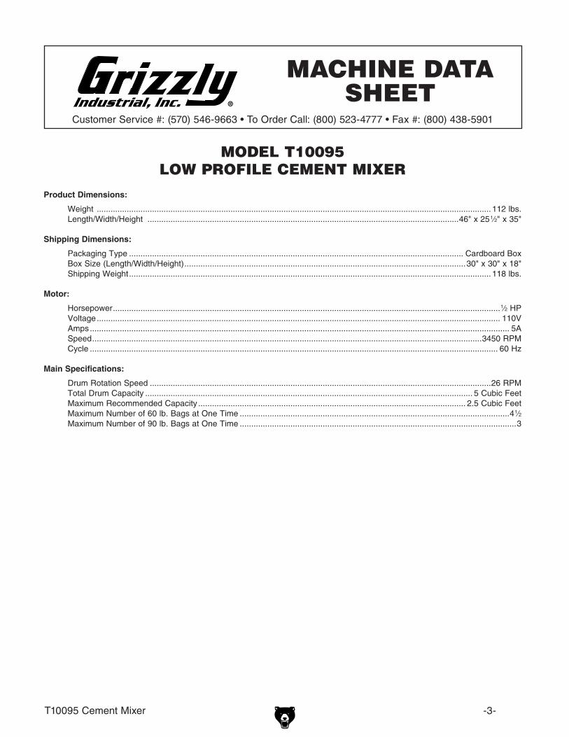
MODEL T10095LOW PROFILE CEMENT MIXER
MACHINE DATA SHEET
Product Dimensions:
Shipping Dimensions:
Motor:
Main Specifications:
Machine Data Sheet
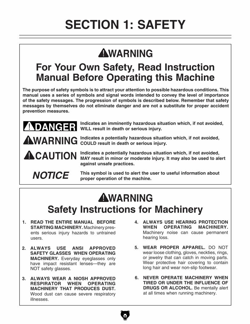
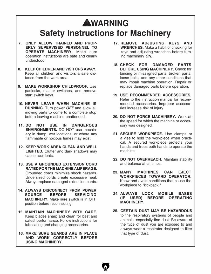
Safety Instructions for Machinery
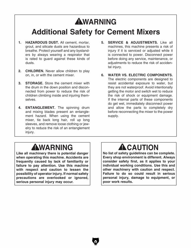
additional Safety for Cement Mixers5. SERvICE & aDJuSTMENTS. like all
machines, this machine presents a risk of injury if it is serviced or adjusted while it is connected to power. disconnect power before doing any service, maintenance, or adjustments to reduce the risk of acciden-tal injury.
6. WaTER vS. ELECTRIC COMPONENTS. the electric components are designed to resist accidental exposure to water, but they are not waterproof. Avoid intentionally getting the motor and switch wet to reduce the risk of shock or equipment damage. if the internal parts of these components do get wet, immediately disconnect power and allow the parts to completely dry before reconnecting the mixer to the power supply.
1. hazaRDOuS DuST. All cement, mortar, grout, and silicate dusts are hazardous to breathe. protect yourself and any bystand-ers by always wearing a respirator that is rated to guard against these kinds of dusts.
2. ChILDREN. never allow children to play on, in, or with the cement mixer.
3. STORagE. Store the cement mixer with the drum in the down position and discon-nected from power to reduce the risk of children climbing inside and injuring them-selves.
4. ENTaNgLEMENT. the spinning drum and mixing blades present an entangle-ment hazard. When using the cement mixer, tie back long hair, roll up long sleeves, and remove loose clothing or jew-elry to reduce the risk of an entanglement injury.
No list of safety guidelines can be complete. Every shop environment is different. always consider safety first, as it applies to your individual working conditions. use this and other machinery with caution and respect. Failure to do so could result in serious personal injury, damage to equipment, or poor work results.
Like all machinery there is potential danger when operating this machine. accidents are frequently caused by lack of familiarity or failure to pay attention. use this machine with respect and caution to lessen the possibility of operator injury. If normal safety precautions are overlooked or ignored, serious personal injury may occur.

t10095 Cement Mixer -7-
Figure 1. typical 5-15 plug and receptacle.
110v Operation
Full Load amperage Drawthis machine draws the following amps under maximum load:
Amp draw ................................................5 Amps
Power Supply Circuit Requirementsyou MUSt connect your machine to a grounded circuit that is rated for the amperage given below. never replace a circuit breaker on an existing cir-cuit with one of higher amperage without consult-ing a qualified electrician to ensure compliance with wiring codes. If you are unsure about the wiring codes in your area or you plan to con-nect your machine to a shared circuit, consult a qualified electrician.
Minimum Circuit Size .............................15 Amps
This machine MuST have a ground prong in the plug to help ensure that it is grounded. DO NOT remove ground prong from plug to fit into a two-pronged outlet! If the plug will not fit the outlet, have the proper outlet installed by a qualified electrician.
Extension CordsWe do not recommend using extension cords, but if you find it absolutely necessary:
• Use at least a 14 gauge cord that does not exceed 50 feet in length!
• the extension cord must have a ground wire and plug pin.
• A qualified electrician MUSt size cords over 50 feet long to prevent motor damage.
SECTION 2: CIRCuIT REQuIREMENTS
Serious personal injury could occur if you connect the machine to power before completing the setup process. DO NOT connect the machine to the power until instructed later in this manual.
Electrocution or fire could result if machine is not grounded and installed in compliance with electrical codes. Compliance MuST be verified by a qualified electrician!
Power Connection Devicethe Model t10095 comes with a 5-15 plug, similar to Figure 1, to connect the machine to power.

-8- t10095 Cement Mixer
SECTION 3: SETuP
Wear safety glasses during the entire setup process!
This machine presents serious injury hazards to untrained users. Read through this entire manual to become familiar with the controls and operations before starting the machine!
Setup Safety
This machine and its components are very heavy. To avoid personal injury, get help lifting the heavy items.
your machine was carefully packaged for safe transportation. remove the packaging materials from around your machine and inspect it. if you discover the machine is damaged, please imme-diately call Customer Service at (570) 546-9663 for advice.
Save the containers and all packing materials for possible inspection by the carrier or its agent. Otherwise, filing a freight claim can be difficult.
When you are completely satisfied with the condi-tion of your shipment, inventory the contents.
unpacking
the following items are needed to complete the setup process, but are not included with your machine:
Description Qty• Wrench or Socket 17mm ............................ 1• Wrench or Socket 13mm ............................ 1• Wrench or Socket 12mm ............................ 1• Wrench or Socket 10mm ............................ 1• phillips Screwdriver #2 ............................... 1• Anti-Seize paste (optional) ........................ 1• Contact Adhesive (optional) ...................... 1• Bearing grease ................................. 1 tbsp
Items Needed for Setup

t10095 Cement Mixer -9-
Figure 2. inventory components picture 1.
A
e
F
g
h
i
Kl
d
B C
J
Inventory
After all the parts have been removed from the carton, you should have:
Main Components (Figure 2) Qtya. Motor Assembly .......................................... 1b. Frame ......................................................... 1C. Upper drum ................................................ 1D. hardware Bag ............................................ 1E. handles ...................................................... 2F. Motor Cover ................................................ 1g. Frame Support ........................................... 1h. Mixing Blades ............................................. 2I. drum gasket .............................................. 1J. Wheels ....................................................... 2K. Axle rod ..................................................... 1L. lower drum ................................................ 1
hardware bag Contents (Figure 3) Qtya. hex Bolts M8-1.25 x 80 (Frame Assy) ....... 8b. Curved Washers 8mm (Frame Assy) ....... 16C. lock nuts M8-1.25 (Frame Assy) .............. 8D. Flat Washers 6mm (Motor-to-Frame) ......... 6E. lock Washers 6mm (Motor-to-Frame) ....... 6F. lock nuts M6-1 (Motor-to-Frame) .............. 6g. phillips Screws M6-1 x 16 (Motor Cover)... 2h. hex nuts M6-1 (Motor Cover) .................... 2I. threaded pin M10-1.5 (drum-to-Shaft) ..... 1J. lock nut M10-1.5 (drum-to-Shaft) ............. 1K. hex Bolts M6-1 x 20 (drum-to-drum) ........ 6L. Fender Washers 6mm (drum-to-drum) ..... 6M. Flat Washers 6mm (drum-to-drum) ........... 6N. lock Washers 6mm (drum-to-drum) ......... 6O. hex nuts M6-1 (drum-to-drum) ................. 6P. hex Bolts M10-1.5 x 25 (Mixing Blade) ..... 4Q. hex nuts M10-1.5 (Mixing Blade) .............. 4R. Wrench 12/10mm ....................................... 1S. Wrench 17/14mm ....................................... 1
NOTICESome hardware/fasteners on the inventory list may arrive pre-installed. Check mounting locations before assuming that any items from the inventory list are missing.
if any nonproprietary parts are missing (e.g. a nut or a washer), we will gladly replace them; or for the sake of expediency, replacements can be obtained at your local hardware store.
K
Figure 3. inventory components picture 2.
A
B
C
d
e
F
K
l
M
n
o
g
hi
J
p
Q
r
S
-10- t10095 Cement Mixer
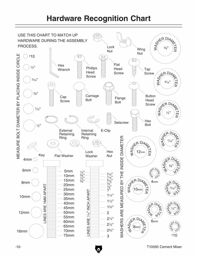
hardware Recognition Chart
t10095 Cement Mixer -11-
assembly
To assemble the cement mixer:
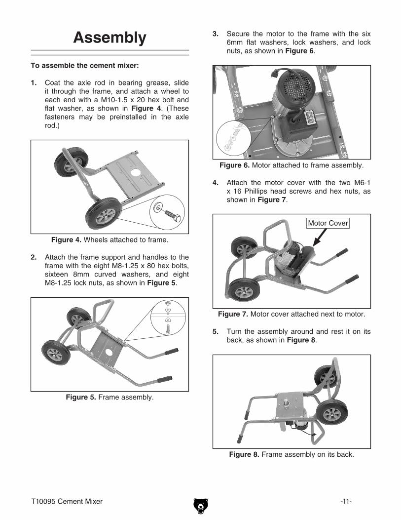
1. Coat the axle rod in bearing grease, slide it through the frame, and attach a wheel to each end with a M10-1.5 x 20 hex bolt and flat washer, as shown in Figure 4. (these fasteners may be preinstalled in the axle rod.)
Figure 4. Wheels attached to frame.
Figure 5. Frame assembly.
2. Attach the frame support and handles to the frame with the eight M8-1.25 x 80 hex bolts, sixteen 8mm curved washers, and eight M8-1.25 lock nuts, as shown in Figure 5.
3. Secure the motor to the frame with the six 6mm flat washers, lock washers, and lock nuts, as shown in Figure 6.
Figure 6. Motor attached to frame assembly.
4. Attach the motor cover with the two M6-1 x 16 phillips head screws and hex nuts, as shown in Figure 7.
Figure 7. Motor cover attached next to motor.
5. turn the assembly around and rest it on its back, as shown in Figure 8.
Figure 8. Frame assembly on its back.
Motor Cover
-12- t10095 Cement Mixer
Test Run
once assembly is complete and you have read and understand this entire owner's manual, con-nect the machine to the power source, then test it to make sure it runs properly.
if there is an unusual noise or vibration, stop the machine immediately and inspect it for loose fasteners or improperly assembled pieces. if you still cannot remedy a problem, contact our tech Support at (570) 546-9663 for assistance.
10. if available, apply anti-seize paste on the M10-1.5 x 25 hex bolts, then use them with the M10-1.5 hex nuts to secure the two mix-ing blades to the inside of the drum assem-bly, as shown in Figure 13.
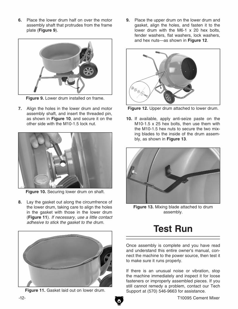
6. place the lower drum half on over the motor assembly shaft that protrudes from the frame plate (Figure 9).
Figure 9. lower drum installed on frame.
7. Align the holes in the lower drum and motor assembly shaft, and insert the threaded pin, as shown in Figure 10, and secure it on the other side with the M10-1.5 lock nut.
Figure 10. Securing lower drum on shaft.
8. lay the gasket out along the circumfrence of the lower drum, taking care to align the holes in the gasket with those in the lower drum (Figure 11). If necessary, use a little contact adhesive to stick the gasket to the drum.
Figure 11. gasket laid out on lower drum.
9. place the upper drum on the lower drum and gasket, align the holes, and fasten it to the lower drum with the M6-1 x 20 hex bolts, fender washers, flat washers, lock washers, and hex nuts—as shown in Figure 12.
Figure 12. Upper drum attached to lower drum.
Figure 13. Mixing blade attached to drum assembly.
t10095 Cement Mixer -13-
Follow the tips below when using the cement mixer:
• Before using your cement mixer, coat the inside of the mixing drum with a light layer of vegetable oil. refer to Lubrication on Page 14 for more details.
• Spray the inside surface of the cement mixer with a small amount of water before adding cement (in addition to the lubrication steps above). this will make it easier to clean after operation. Avoid spraying water on the switch or motor!
• the mixer works more effectively and quickly when batches are half the maximum recom-mended mixture load, or if mixture materials are added slowly (while mixing), rather than all at one time.
• the maximum recommended mixture load is 2.5 cubic feet. this equates to:
— Four and a half 60 lb. bags— three 90 lb. bags
Operation Tips
SECTION 4: OPERaTIONS
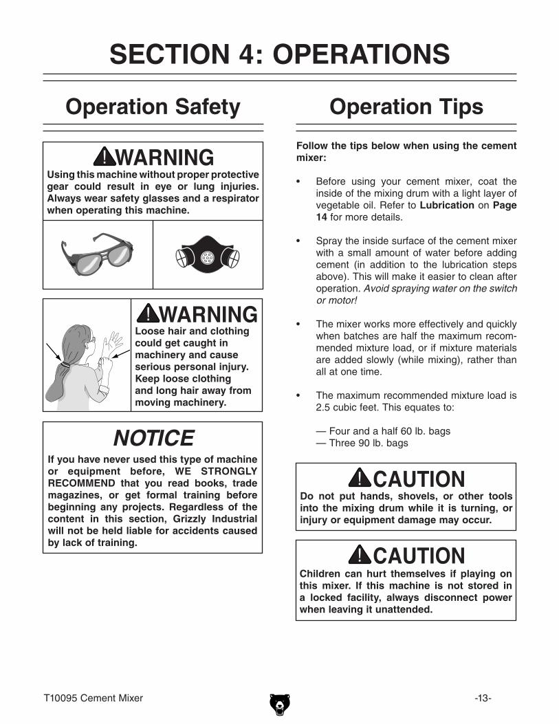
using this machine without proper protective gear could result in eye or lung injuries. always wear safety glasses and a respirator when operating this machine.
Loose hair and clothing could get caught in machinery and cause serious personal injury. Keep loose clothing and long hair away from moving machinery.
Operation Safety
NOTICEIf you have never used this type of machine or equipment before, WE STRONgLy RECOMMEND that you read books, trade magazines, or get formal training before beginning any projects. Regardless of the content in this section, grizzly Industrial will not be held liable for accidents caused by lack of training.
Children can hurt themselves if playing on this mixer. If this machine is not stored in a locked facility, always disconnect power when leaving it unattended.
Do not put hands, shovels, or other tools into the mixing drum while it is turning, or injury or equipment damage may occur.
-14- t10095 Cement Mixer
• Always unplug the cement mixer before cleaning.
• Avoid getting water on the motor or switch while cleaning. if you do, allow the compo-nents to thoroughly dry before plugging in the motor.
• the easiest way to clean the drum is by hosing it out with water. (Cleaning is made much easier if you follow the Lubrication procedures in this section before using your cement mixer.)
• Always clean the mixing drum immediately after using it. As a general rule, the sooner you clean, the easier it will be.
• For tough to remove buildup, use a stiff bristle brush or a rag to make cleaning easier.
• Small, hardened cement splatters usually can be removed by rubbing with a dry rag.
• hardened cement can be scraped, chiseled or pounded off with a hammer; however, these actions Will damage the surface area of the drum, making it harder to clean in the future.
Cleaning
SECTION 5: MaINTENaNCE
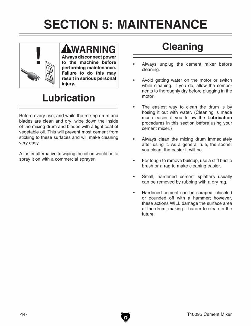
always disconnect power to the machine before performing maintenance. Failure to do this may result in serious personal injury.
Before every use, and while the mixing drum and blades are clean and dry, wipe down the inside of the mixing drum and blades with a light coat of vegetable oil. this will prevent most cement from sticking to these surfaces and will make cleaning very easy.
A faster alternative to wiping the oil on would be to spray it on with a commercial sprayer.
Lubrication
t10095 Cement Mixer -15-
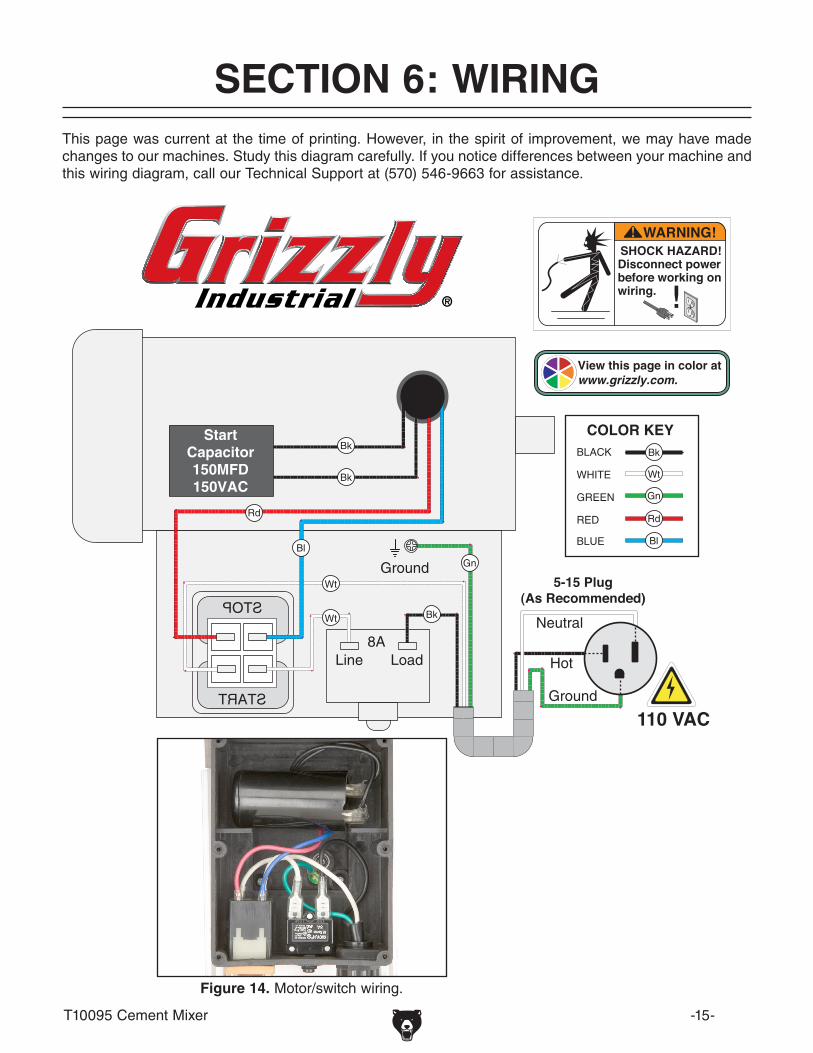
WARNING!SHOCK HAZARD!Disconnect power before working on wiring.
View this page in color at www.grizzly.com.
StartCapacitor150MFD150VAC
110 VAC
5-15 Plug(As Recommended)
Figure 14. Motor/switch wiring.
this page was current at the time of printing. however, in the spirit of improvement, we may have made changes to our machines. Study this diagram carefully. if you notice differences between your machine and this wiring diagram, call our technical Support at (570) 546-9663 for assistance.
SECTION 6: WIRINg

-16- t10095 Cement Mixer
Parts breakdown
SECTION 7: PaRTS

t10095 Cement Mixer -17-
REF PART # DESCRIPTION REF PART # DESCRIPTION1 PB32M HEX BOLT M10-1.5 X 25 19-5 PT10095019-5 ON/OFF SWITCH2 PN02M HEX NUT M10-1.5 19-6 PT10095019-6 JUNCTION BOX3 PW04M FLAT WASHER 10MM 20 PT10095020 SPECIAL SCREW M10-1.5 X 654 PT10095004 UPPER DRUM 21 PT10095021 CURVED WASHER 8MM5 PB08M HEX BOLT M6-1 X 20 22 PLN04M LOCK NUT M8-1.256 PWF06M FENDER WASHER 6MM 23 PT10095023 STAND SUPPORT7 PT10095007 MIXER BLADE 24 PT10095024 STAND8 PT10095008 DRUM GASKET 25 PB82M HEX BOLT M8-1.25 X 809 PT10095009 LOWER DRUM 26 PT10095026 WHEEL 10 PW03M FLAT WASHER 6MM 27 PWF10M FENDER WASHER 10MM11 PLW03M LOCK WASHER 6MM 28 PB48M HEX BOLT M10-1.25 X 2012 PN01M HEX NUT M6-1 29 PT10095029 AXLE13 PT10095013 UPPER COVER 30 PT10095030 BUSHING14 PT10095014 SPECIAL WASHER 10MM 31 PS11M PHLP HD SCR M6-1 X 1615 PLN05M LOCK NUT M10-1.5 32 PT10095032 PIN 5 X 40MM16 PT10095016 HANDLE 33 PWR1012 WRENCH 10/12MM17 PT10095017 HANDLE GRIP 34 PT10095034 WRENCH 14/17MM18 PT10095018 MOTOR COVER 35 PT10095035 MACHINE ID LABEL19 PT10095019 MOTOR/GEARBOX ASSEMBLY 36 PLABEL-53B DISCONNECT POWER LABEL19-1 PT10095019-1 MOTOR FAN COVER 37 PLABEL-12 READ MANUAL LABEL19-2 PT10095019-2 MOTOR FAN 38 PLABEL-57B GLASSES RESPIRATOR LABEL19-3 PT10095019-3 CIRCUIT BREAKER 39 PT10095039 NO WATER LABEL19-4 PT10095019-4 S CAP 150M 150V 1-1/2" X 2-3/4" 40 PLABEL-14 ELECTRICITY LABEL
Parts List
Safety labels warn about machine hazards and ways to prevent injury. The owner of this machine MuST maintain the original location and readability of the labels on the machine. If any label is removed or becomes unreadable, REPLaCE that label before using the machine again. Contact grizzly at (800) 523-4777 or www.grizzly.com to order new labels.

-18- t10095 Cement Mixer


WaRRaNTy aND RETuRNS