Model ST-3050D Submersible Pump - Multiquip Inc
38
OPERATION AND PARTS MANUAL Revision #2 (06/15/16) Model ST-3050D Submersible Pump THIS MANUAL MUST ACCOMPANY THE EQUIPMENT AT ALL TIMES.
Transcript of Model ST-3050D Submersible Pump - Multiquip Inc
OPERATION AND PARTS MANUAL
Revision #2 (06/15/16)
Model ST-3050DSubmersible Pump
THIS MANUAL MUST ACCOMPANY THE EQUIPMENT AT ALL TIMES.

PAGE 2 — ST-3050D — OPERATION AND PARTS MANUAL — REV. #2 (06/15/16)
HERE'S HOW TO GET HELPPLEASE HAVE THE MODEL AND SERIAL NUMBERON-HAND WHEN CALLING
PARTS DEPARTMENT800/427-1244 or 310/537-3700FAX: 800/672-7877 or 310/637-3284
SERVICE DEPARTMENT800/478-1244 or 310/537-3700FAX: 310 - 537-4259
WARRANTY DEPARTMENT800/421-1244, EXT. 279 or 310/537-3700FAX: 310 - 537-1173
MAIN800/421-1244 or 310/537-3700FAX: 310 - 537-3927

ST-3050D — OPERATION AND PARTS MANUAL — REV. 2 (06/15/16) — PAGE 3
ST-3050D SUBMERSIBLE PUMP — TABLE OF CONTENTS
Here's How To Get Help ............................................2Table Of Contents .....................................................3Parts Ordering Procedures .......................................4Safety Message Alert Symbols .................................5Rules For safe Operation ..................................... 6-7Specifications (Pump) ...............................................7General Information ..................................................9
ST-3050D SubmersiblePumpComponents ............................................................10Application (Float Switches) ....................................11Control Boxes..........................................................12Control Box Installation (CB200) .............................13230/460 VAC Voltage Selection ...............................14Pump Wiring Diagram .............................................15Transformer Wiring Diagram (CB200) ....................16Control Box Wiring Diagram (CB200) .....................17Three-Phase Power Installation (CB200) ......... 18-19Control Box Pre-Setup (CB200) ........................ 20-21Control Box Installation (MP102/104) .....................22Control Box Wiring Diagram (MP102/104)..............23Operation .......................................................... 24-25Maintenance ...........................................................26Pump Troubleshooting/Performance Curve ............27Explanation Of Codes In Remarks Column ............28Suggested Spare Parts ...........................................29Electric Submersible Pump Assembly .............. 30-33Electric Motor Assembly.................................... 34-35
Terms and Condition of Sale — Parts .....................36
NOTE
Specification andpart number aresubject to changewithout notice.

PAGE 4 — ST-3050D — OPERATION AND PARTS MANUAL — REV. #2 (06/15/16)
PARTS ORDERING PROCEDURESw
ww
.multiq
uip
.com
Ordering parts has never been easier! Choose from three easy options:
WE ACCEPT ALL MAJOR CREDIT CARDS!
When ordering parts, please supply:❒ Dealer Account Number❒ Dealer Name and Address❒ Shipping Address (if different than billing address)❒ Return Fax Number❒ Applicable Model Number❒ Quantity, Part Number and Description of Each Part
❒ Specify Preferred Method of Shipment: ✓ UPS/Fed Ex ✓ DHL ■ Priority One ✓ Truck ■ Ground ■ Next Day ■ Second/Third Day
If you have an MQ Account, to obtain a Username and Password, E-mail us at: [email protected].
To obtain an MQ Account, contact your District Sales Manager for more information.
Order via Internet (Dealers Only):Order parts on-line using Multiquip’s SmartEquip website! ■ View Parts Diagrams ■ Order Parts ■ Print Specification Information
Note: Discounts Are Subject To Change
Goto www.multiquip.com and click on Order Parts to log in and save!
Use the internet and qualify for a 5% Discount on Standard orders for all orders which include complete part numbers.*
Order via Fax (Dealers Only):All customers are welcome to order parts via Fax.Domestic (US) Customers dial: 1-800-6-PARTS-7 (800-672-7877)
Fax your order in and qualify for a 2% Discount on Standard orders for all orders which include complete part numbers.*
Order via Phone: Domestic (US) Dealers Call: 1-800-427-1244
Best Deal!
International Customers should contact their local Multiquip Representatives for Parts Ordering information.
Non-Dealer Customers: Contact your local Multiquip Dealer for parts or call 800-427-1244 for help in locating a dealer near you.
Note: Discounts Are Subject To Change
Effective: January 1st, 2006
NOTICE
All orders are treated as Standard Orders and will ship the same day if received prior to 3PM PST.
ST-3050D — OPERATION AND PARTS MANUAL — REV. 2 (06/15/16) — PAGE 5
ST-3050D SUBMERSIBLE PUMP— SAFETY MESSAGE ALERT SYMBOLS
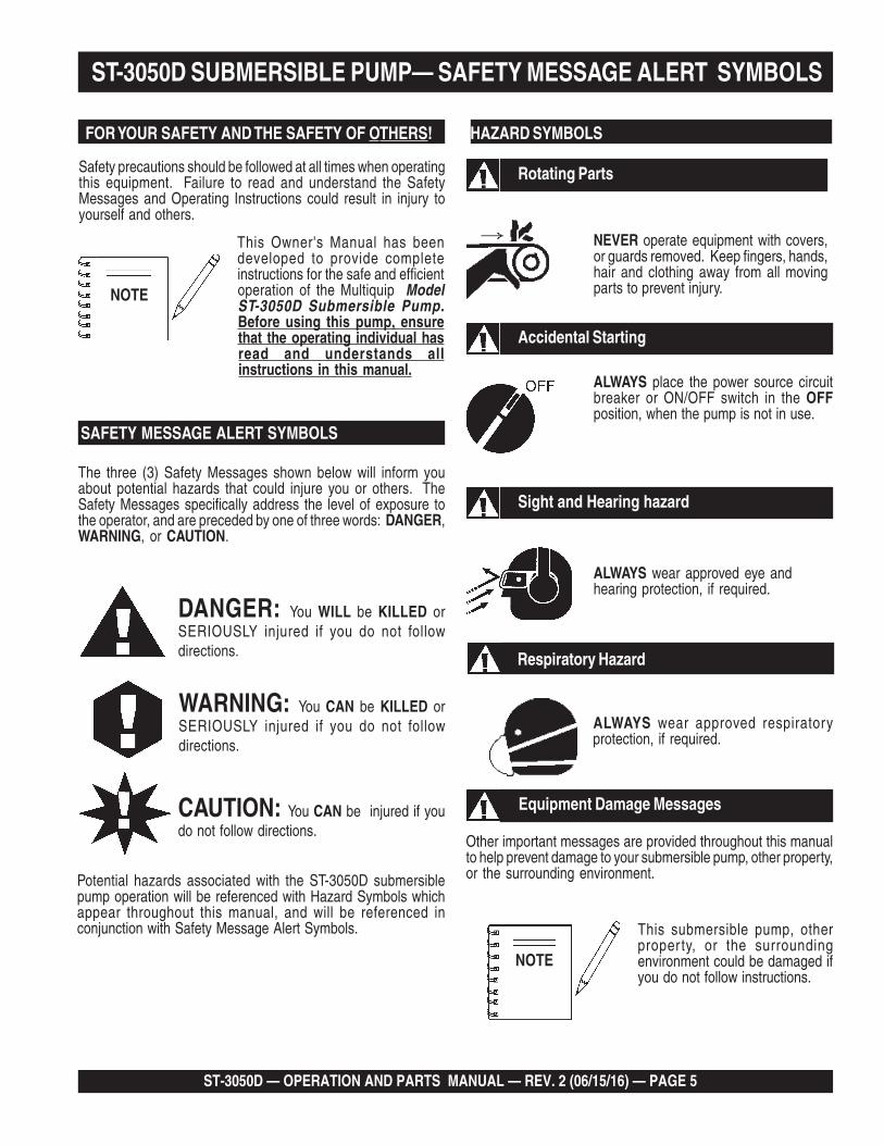
Safety precautions should be followed at all times when operatingthis equipment. Failure to read and understand the SafetyMessages and Operating Instructions could result in injury toyourself and others.
FOR YOUR SAFETY AND THE SAFETY OF OTHERS!
This Owner's Manual has beendeveloped to provide completeinstructions for the safe and efficientoperation of the Multiquip ModelST-3050D Submersible Pump.Before using this pump, ensurethat the operating individual hasread and understands allinstructions in this manual.
SAFETY MESSAGE ALERT SYMBOLS
The three (3) Safety Messages shown below will inform youabout potential hazards that could injure you or others. TheSafety Messages specifically address the level of exposure tothe operator, and are preceded by one of three words: DANGER,WARNING, or CAUTION.
DANGER: You WILL be KILLED orSERIOUSLY injured if you do not followdirections.
WARNING: You CAN be KILLED orSERIOUSLY injured if you do not followdirections.
CAUTION: You CAN be injured if youdo not follow directions.
HAZARD SYMBOLS
Potential hazards associated with the ST-3050D submersiblepump operation will be referenced with Hazard Symbols whichappear throughout this manual, and will be referenced inconjunction with Safety Message Alert Symbols.
Rotating Parts
NEVER operate equipment with covers,or guards removed. Keep fingers, hands,hair and clothing away from all movingparts to prevent injury.NOTE
Accidental Starting
ALWAYS place the power source circuitbreaker or ON/OFF switch in the OFFposition, when the pump is not in use.
ALWAYS wear approved eye andhearing protection, if required.
Sight and Hearing hazard
Respiratory Hazard
ALWAYS wear approved respiratoryprotection, if required.
Equipment Damage Messages
Other important messages are provided throughout this manualto help prevent damage to your submersible pump, other property,or the surrounding environment.
This submersible pump, otherproperty, or the surroundingenvironment could be damaged ifyou do not follow instructions.
NOTE

PAGE 6 — ST-3050D — OPERATION AND PARTS MANUAL — REV. #2 (06/15/16)
ST-3050D SUBMERSIBLE PUMP — RULES FOR SAFE OPERATION
CAUTION:Failure to follow instructions in this manual maylead to serious injury or even death! Thisequipment is to be operated by trained andqualified personnel only! This equipment is forindustrial use only.
The following safety guidelines should always be used whenoperating the ST-3050D Submersible Pump:
GENERAL SAFETY
■ DO NOT operate or service this equipmentbefore reading this entire manual.
■ This equipment should not be operated by persons under 18years of age.
■ NEVER operate this equipment without properprotective clothing, shatterproof glasses, steel-toedboots and other protective devices required by thejob.
■ NEVER operate this equipment when not feelingwell due to fatigue, illness or taking medicine.
■ NEVER operate this equipment under theinfluence or drugs or alcohol.
■ NEVER use accessories or attachments, which are notrecommended by Multiquip for this equipment. Damage to theequipment and/or injury to user may result.
■ Manufacture does not assume responsibility for any accidentdue to equipment modifications.
■ Whenever necessary, replace nameplate, operation and safetydecals when they become difficult read.
■ ALWAYS check the machine for loosened threads or boltsbefore starting.
■ NEVER operate the submersible pump in an explosiveatmosphere or near combustible materials. An explosion or firecould result causing severe bodily harm or even death.
■ ALWAYS make sure submersible pump is grounded.
■ NEVER use gas piping as an electrical ground.
■ DO NOT place hands or fingers inside pump when pump isrunning.
■ ALWAYS make certain that the voltage supplied to the pumpis correct. Always read the pump's nameplate to determinewhat the power requirements are (230 or 460 VAC 3 phase).
■ DO NOT restrict the flow of the discharge hose as it maycause overheating.
■ Be careful of discharge whipping under pressure.
■ Make sure pump installation is accordance with nationaland local electrical codes.
■ ALWAYS have a qualified electrician perform the pumpwiring installation.
■ ALWAYS mount the control box in a vertical positionprotected from the elements.
■ NEVER handle pump's AC power cord with wet hands.
■ NEVER let an extension cord or plug connection lay in water.
■ NEVER stand in water while AC power cord is connectedto a power source.
■ NEVER use a pump with a defective, frayed power cord.Check the power cord on the pump for cuts in the insulation.
■ NEVER use a extension cord that is frayed or damagedwhere the insulation has been cut.
■ ALWAYS make certain that proper extension cord has beenselected for the job See Table 3.
■ NEVER attempt to use the power cord as a lifting or loweringdevice for the submersible pump.
■ When raising or lowering of the submersible pump isrequired, always attach an adequate rope or lifting deviceto the correct lifting point (handle) on the pump.
■ ALWAYS place the pump in an up-right position on aplatform before using. The platform will prevent the pumpfrom burrowing itself on soft sand or mud.
■ NEVER operate pump on its side.
■ DO NOT allow the pump to freeze in water.
■ NEVER leave an open pump chamber unattended.
■ The electrical voltage required to operate the pump cancause severe injury or even death through physical contactwith live circuits. ALWAYS disconnect the electrical powerfrom the pump before performing maintenance on the pump.

ST-3050D — OPERATION AND PARTS MANUAL — REV. 2 (06/15/16) — PAGE 7
ST-3050D SUBMERSIBLE PUMP — RULES FOR SAFE OPERATION. Emergencies
■ ALWAYS know the location of the nearest fire extinguisher.
■ ALWAYS know the location of the nearest and first aid kit.
■ In emergencies always know the location of thenearest phone or keep a phone on the job site.Also know the phone numbers of the nearestambulance, doctor and fire department. Thisinformation will be invaluable in the case of anemergency.
■ ALWAYS make sure that electrical circuits are properlygrounded per the National Electrical Code (NEC) andlocal codes before operating pump. Severe injury or death byelectrocution can result from operating an ungrounded pump.
■ NEVER use this pump to remove water from a swimming poolwhen people are in the water.
■ ALWAYS be sure the operator is familiar with proper safetyprecautions and operations techniques before usingsubmersible pump.
■ ALWAYS check pump oil level only when pump is cool.Expansion due to heat may cause hot! oil to spray from the oilplug when the oil plug is removed.
■ DO NOT attempt to thaw-out a frozen pump by using a torchor other source of flame. Application of heat in this mannermay heat the oil in the seal cavity above the critical point,causing pump damage.
■ DO NOT pump water greater than 104 degrees Fahrenheit.Also DO NOT pump liquids containing acid or alkali.
■ ALWAYS check the dual voltage connection inside the pumpfor proper voltage setting.
■ ALWAYS check strainer before pumping. Make sure straineris not clogged. Remove any large objects, dirt or debris fromthe strainer to prevent clogging.
■ ALWAYS use a large basket strainer when pumping waterthat contain large debris.
■ ALWAYS flush pump (clean) after use when pumping waterconcentrated with heavy debris. It is very important to alwaysflush the pump before turning it off to prevent clogging.
■ ALWAYS store equipment properly when it is not being used.Equipment should be stored in a clean, dry location out of thereach of children.
■ ALWAYS read, understand, and follow procedures inOperator’s Manual before attempting to operate equipment.
Maintenance Safety■ NEVER lubricate components or attempt service on a running
machine.
■ ALWAYS allow the machine a proper amount of time to coolbefore servicing.
■ Keep the machinery in proper running condition.
■ Fix damage to the machine immediately and always replacebroken parts.

PAGE 8 — ST-3050D — OPERATION AND PARTS MANUAL — REV. #2 (06/15/16)
ST-3050D SUBMERSIBLE PUMP — SPECIFICATIONS
)pmuP(snoitacificepS.1elbaT
pmuP
ledoM D0503-TS
epyT pmuPhsarTelbisrembuS
eziSegrahcsiD&noitcuS ).mm67(.ni00.3
yticapaCgnipmuPmumixaMetunim/snollag072)etunim/sretil220,1(
retemaiDsdiloS.xaM ).mm15(.ni00.2
tfiL.xaM )sretem26.7(.tf52
daeH.xaM )sretem00.62(.tf68
rewoP )wK57.3(PH5
esahPegatloV 3064/032 ø
spmAgnitratSCAV032@77CAV064@93
deriuqeRxoBlortnoC seY
noitcetorPdaolrevOlamrehT seY
noitatoR esiwkcolC-retnuoC 1
yticapaClaeSliOlacinahceM )sretiL81.(.cc081 2
ecnaraelCrellepmI.ni520.-210.
).mm536.-403.(
)deepS(MPR 03±055,3
htgneLelbaCrewoP )sreteM26.7(.TF52
snoisnemiD)retemaiDXthgieH(
.ni8.62x2.01).mc86X9.52(
thgieWteNyrD ).gK45(.sbl021
1. Motor Rotation – Upon start-up, the pump "kicks" in the opposite direction of motor rotation. The correct rotation is counter-clockwise (CCW) as viewed from the impeller end of the pump. Rotation direction for 3-phase pumps is changed by reversingtwo of the power leads.
2. Mechanical Oil Seal – Use a good grade 10 weight non-detergent hydraulic oil (i.e. Shell Turbo 32 or equivalent). Fill oil cavity75% to 85% full (allow air space for expansion).
ST-3050D — OPERATION AND PARTS MANUAL — REV. 2 (06/15/16) — PAGE 9
ST-3050D SUBMERSIBLE PUMP — GENERAL INFORMATION
Introduction
The Multiquip Model ST-3050D submersible pump is designedto pump water and is used for the draining (de-watering) ofswimming pools, well casings construction sites, cofferdams,manholes, transformer vaults and excavations.
A vortex type impeller is attached to the output shaft of a 5.0 HPelectric motor which provides adequate power for generalpurpose pumping. This submersible pump is supplied completewith an electric power cable, and a discharge port located at thetop of the pump which accepts a 3-inch hose.
This pump is ideal for portability because of its light weight andcarrying handle. For reliability and long life, a mechanical sealprovides shaft sealing, with an oil chamber separating the pumpsection from the motor.
The pump when in use, should be installed as free standing(upright position) on its strainer base. A 3-inch discharge hose(not supplied) should be connected to the discharge port locatedon top of the pump. The discharge hose should be adequatelysupported to avoid stress on the pump.
For maximum water flow, the discharge hose should be kept asshort as possible, and with minimum elevation above the pump.Remember as the length and/or height of the discharge hose isincreased, the flow of water will be reduced. Also any reductionin the hose size, and any fittings such as valves or outlet nozzles,will restrict the water flow.
To avoid back-siphonage when the pump is switched off, ensurethat the end of the discharge hose is installed above the waterlevel at the final discharge point.
When the pump is switched off, the water remaining in the hosewill run back through the pump. This can be avoided by placinga non-return valve in the hose nearest the pump.
NEVER use this submersible pump to pump flammable liquidsor operate in a explosive or flammable environment.
Avoid using this pump in conditions where mud, grit, silt or otherdebris are present. These conditions could cause blockage andcause excessive pump wear.
DO NOT install the pump directly into an area where there is aheavy build-up of mud, grit, silt or debris. If this condition is present,install the pump on a platform before operating.
This pump must always be positioned on a platform in an uprightposition. NEVER operate the pump by a suspended rope. Toprevent large solids from entering the pump, install a wire meshscreen or similar barrier around the pump.
If the pump was used to pump water containing mud, silt, useclean water to flush out the pump after each use.
DO NOT allow the pump to run dry, as this will damage thepump. During maintenance, dry running is permissible but onlyfor a few seconds.
NEVER lift the pump by its electrical power cord. ALWAYS liftthe pump by its carrying handle or attached a rope to carryinghandle.
A pump fully submerged pump in liquid will not freeze, unlessthe liquid freezes. DO NOT allow a partially submerged pump tofreeze. The expansion of water freezing in the volute may crackthe pump, causing expensive repairs. If there is any danger ofthe pump being subjected to freezing temperatures, Lift the pumpfrom water and allow it to drain thoroughly.
If the pump jams or the pump rotor locks for any reason,disconnect the pump from the power source immediately.Allowing the pump motor to cycle ON and OFF under an overloadcondition can burn out the motor.
When replacement of nuts and bolts is required, use onlyrecommended parts as referenced in the parts section of thismanual. This pump uses metric threads. DO NOT use englishmeasurement threads.

PAGE 10 — ST-3050D — OPERATION AND PARTS MANUAL — REV. #2 (06/15/16)
ST-3050D SUBMERSIBLE PUMP — COMPONENTS
Figures 1 shows the location of the basic components, for theST-3050D Submersible Pump. Listed below is a brief explanationof each component.
1. Strainer Base – This strainer base is made of stainlesssteel which is resistant to hardware corrosion. DO NOTpump large objects or debris with this pump. This pump isfor pumping water only. For de-watering purposes, alwaysplace the strainer base on a platform.
2. Volute/Impeller – Impellers are constructed of high-chromeductile iron to minimizes wear and prolong service life.
3. Electric Motor – This unit utilizes a three-phase, 230/460VAC, 5.0 HP electric motor. Consult with a licencedelectrician before connecting motor to a power source.Observe all city and local safety codes.
4. Discharge Port – Connect a 3-inch hose to this port.Remember to adequately support the discharge hose toavoid stress on the pump.
5. AC Power Cable – This unit is supplied with a 50 ft. (15.24meters) AC power cable. Always check the cable for signsof wear. NEVER! use a defective power cable. Replace thecable immediately if the cable is worn or defective.
6. Carrying Handle – Always carry the submersible pumpby its handle. NEVER! carry the pump by its power cord.Carrying or lifting the pump by the power cord, will causeundue stress on the cord, and ultimately the cord willbecome dislodged from the pump.
7. Thermal Overload Protection – This pump will requirethe use of an external control box with a thermal overloadprotection device that will shut-down the motor in the eventof high operating temperatures. The motor will automaticallyrestart once the temperature returns to an acceptableoperating temperature.
8. Mechanical Oil Seal – This oil filled seal provideslubrication when running the pump dry. NEVER! run thepump dry. Running the pump dry will cause severe damageto the pump.
9. Mechanical Oil Seal Plug – Remove this plug to checkand add hydraulic oil (Shell 32 or equivalent) to the oilcavity. This oil protects the mechanical seal. Oil cavity shouldbe full enough to cover seal spring.
Figure 1. Submersible Pump Components

ST-3050D — OPERATION AND PARTS MANUAL — REV. 2 (06/15/16) — PAGE 11
ST-3050D SUBMERSIBLE PUMP — APPLICATION (FLOAT SWITCHES)
Float Switch Theory
There is a tilt-sensitive mercury switch hermetically sealed withineach float. As the liquid level (water) rises or falls, the float changesits angle until the mercury switch makes (close) or breaks (open)the circuit.
The length of cord between the float and point of attachmentdetermines the amount of water to be pumped.
Figure 2. Dual Float Control Switch
Float Switch (Dual)
Float switches (Figure 2) are used for the unattended operationof the submersible pump. The ST-3050D pump requires the useof a control box to perform this function. Shown in Figure 2 is anexample of a dual float control switch application.
The Model ST-3050D submersible pump requires one each ofthe Model SW-1WOP float type mercury switches. Theseswitches have a pumping range level between 5.5~18 feet(1.67~5.5 meters). All float switch connections are bare wire (noplug). The ST-3050D submersible pump must use the CB 200Control Box when float switches are required for the jobapplication. The MCP102/104 control boxes do not have floatswitch capability.
Contact Multiquip sales department to order float switches.
SUBMERSIBLEPUMP
ACPOWERINPUT
FLOATSWITCHINPUTS
CONTROL
BOX
ACPOWER
TOPUMP
EXTERNAL 3-PHASE(230 OR 460 VOLT)POWER SOURCE
CIRCUITBREAKER
REDWHITE
BLACK
L1
L2
L3
GR
EE
N
GROUND
PUMPON
PUMPOFF
FLOATSWITCHES
LIFTINGROPE
SUPPORTPLATFORM
3-INCHDISCHARGE
HOSE
ON RESET
MANUALOFF
AUTO
CAUTION!HIGH
VOLTAGE!
CAUTION!HIGH
VOLTAGE!
CB200

PAGE 12 — ST-3050D — OPERATION AND PARTS MANUAL — REV. #2 (06/15/16)
Control Boxes
Control boxes (Figure 3) are available for remote control andthermal shut-down capability for the submersible pump. Thesewater resistant control boxes provide electronic overloadprotection, watertight housing and glands to prevent water fromleaking into the box, and a float switch interface.
There are various control box models to choose from, referenceTable 2 for the model that meets your pumping requirements.
Figure 3. Electrical Control Box (CB-200)
Contact Multiquip sales department to order control boxes aslisted in Table 2.
ST-3050D SUBMERSIBLE PUMP — CONTROL BOXES
ALWAYS have a qualifiedlicensed electrician perform theinstallation of the control box.
AC POWERINPUT
CONTROL
BOX
ON RESET
MANUALOFF
AUTO
CAUTION!HIGH
VOLTAGE!
CAUTION!HIGH
VOLTAGE!
CB200
FLOATSWITCHINPUT
TO PUMP
snoitacifiepSxoBlortnoC.2elbaT
.oNledoM epyTegatloV ASC/LUdetsiL
lamrehTdaolrevOnoitcetorP
taolFhctiwS
ytilibapaC
002BC CAV064/032esahP-eerhT SEY SEY SEY
201PCM CAV032esahP-eerhT SEY SEY ON
401PCM CAV064esahP-eerhT SEY SEY ON
NOTE
ST-3050D — OPERATION AND PARTS MANUAL — REV. 2 (06/15/16) — PAGE 13
ST-3050D SUBMERSIBLE PUMP/CTRL. BOX — INSTALLATION (CB200)
DANGER:
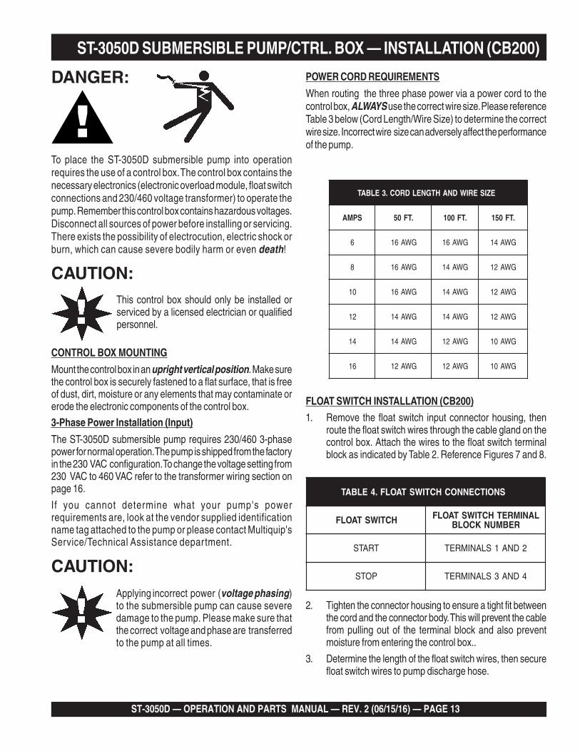
To place the ST-3050D submersible pump into operationrequires the use of a control box. The control box contains thenecessary electronics (electronic overload module, float switchconnections and 230/460 voltage transformer) to operate thepump. Remember this control box contains hazardous voltages.Disconnect all sources of power before installing or servicing.There exists the possibility of electrocution, electric shock orburn, which can cause severe bodily harm or even death!
CAUTION:This control box should only be installed orserviced by a licensed electrician or qualifiedpersonnel.
CONTROL BOX MOUNTING
Mount the control box in an upright vertical position. Make surethe control box is securely fastened to a flat surface, that is freeof dust, dirt, moisture or any elements that may contaminate orerode the electronic components of the control box.
3-Phase Power Installation (Input)
The ST-3050D submersible pump requires 230/460 3-phasepower for normal operation. The pump is shipped from the factoryin the 230 VAC configuration. To change the voltage setting from230 VAC to 460 VAC refer to the transformer wiring section onpage 16.
If you cannot determine what your pump's powerrequirements are, look at the vendor supplied identificationname tag attached to the pump or please contact Multiquip'sService/Technical Assistance department.
EZISERIWDNAHTGNELDROC.3ELBAT S
SPMA .TF05 .TF001 .TF051
6 GWA61 GWA61 GWA41
8 GWA61 GWA41 GWA21
01 GWA61 GWA41 GWA21
21 GWA41 GWA41 GWA21
41 GWA41 GWA21 GWA01
61 GWA21 GWA21 GWA01
Applying incorrect power (voltage phasing)to the submersible pump can cause severedamage to the pump. Please make sure thatthe correct voltage and phase are transferredto the pump at all times.
POWER CORD REQUIREMENTS
When routing the three phase power via a power cord to thecontrol box, ALWAYS use the correct wire size. Please referenceTable 3 below (Cord Length/Wire Size) to determine the correctwire size. Incorrect wire size can adversely affect the performanceof the pump.
CAUTION:
FLOAT SWITCH INSTALLATION (CB200)
1. Remove the float switch input connector housing, thenroute the float switch wires through the cable gland on thecontrol box. Attach the wires to the float switch terminalblock as indicated by Table 2. Reference Figures 7 and 8.
SNOITCENNOCHCTIWSTAOLF.4ELBAT S
HCTIWSTAOLF LANIMRETHCTIWSTAOLFREBMUNKCOLB
TRATS 2DNA1SLANIMRET
POTS 4DNA3SLANIMRET
2. Tighten the connector housing to ensure a tight fit betweenthe cord and the connector body. This will prevent the cablefrom pulling out of the terminal block and also preventmoisture from entering the control box..
3. Determine the length of the float switch wires, then securefloat switch wires to pump discharge hose.

PAGE 14 — ST-3050D — OPERATION AND PARTS MANUAL — REV. #2 (06/15/16)
ST-3050D SUBMERSIBLE PUMP — 230/460 VAC VOLTAGE SELECTION230/460 VAC Voltage Selection
The ST-3050D submersible pump is factory set at 230VAC. To change the voltage from 230 VAC to 460 VAC,perform the following:
1. Remove the four retaining screws that secure the powercord gland assembly to the pump casing, and pull the 230VAC female plug (Figure 4) from the pump's cavity.
2. Un-plug the 230 VAC female plug from the male motorwindings plug and insert the 460 VAC female plug intomale motor windings plug.
3. Re-install the power cord gland assembly back into thepump's cavity. Make sure that the gland is seated correctly.This will prevent any connector pins from bending orbreaking.
4. Insert the four retaining screws and tighten securely
Figure 4. 230/460 VAC Pump Voltage Selection

ST-3050D — OPERATION AND PARTS MANUAL — REV. 2 (06/15/16) — PAGE 15
ST-3050D SUBMERSIBLE PUMP — PUMP WIRING DIAGRAM
Figure 5. Pump Wiring Diagram
PAGE 16 — ST-3050D — OPERATION AND PARTS MANUAL — REV. #2 (06/15/16)
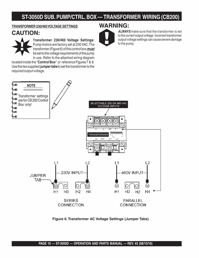
ST-3050D SUB. PUMP/CTRL. BOX — TRANSFORMER WIRING (CB200)TRANSFORMER 230/460 VOLTAGE SETTINGS
CAUTION:Transformer 230/460 Voltage Settings:Pump motors are factory set at 230 VAC. Thetransformer (Figure 6) of this control box mustbe set to the voltage requirements of the pumpin use. Refer to the attached wiring diagram
located inside the "Control Box" or reference Figures 7 & 8.Use the two supplied jumper tabs to set the transformer to therequired output voltage.
WARNING:ALWAYS make sure that the transformer is setto the correct output voltage. Incorrect transformeroutput voltage settings can cause severe damageto the pump.
Figure 6. Transformer AC Voltage Settings (Jumper Tabs)
NOTE
Transformer settingsare for CB 200 ControlBox only!

ST-3050D — OPERATION AND PARTS MANUAL — REV. 2 (06/15/16) — PAGE 17
ST-3050D SUB. PUMP/CONTRL. BOX — WIRING DIAGRAM (CB200)
Figure 7. Control Box Wiring Diagram
NOTEFloat switch connections are foruse with the CB200 Control Boxonly!

PAGE 18 — ST-3050D — OPERATION AND PARTS MANUAL — REV. #2 (06/15/16)
ST-3050D SUB. PUMP/CTRL. BOX — 3Ø PWR. INSTALLATION (CB200)
3-PHASE POWER INSTALLATION (OUTPUT TO PUMP)
1. The three phase output power cord should have four wires.Each wire is color coded. The colors are RED, WHITE,BLACK and GREEN.
2. Remove the 3-phase AC output power connector housingon the control box, then route the three phase output powercable through the cable gland on the control box. Attachthe wires to the AC terminal blocks on the electronicoverload unit as indicated by Table 6 and Figure 8.
3-PHASE POWER CORD (INPUT TO BOX) INSTALLATION
1. The three phase input power cord should have four wires.Each wire is color coded. The colors are RED, WHITE,BLACK and GREEN.
2. Remove the 3-phase AC input connector housing from thecontrol box, then route the three phase input power cablethrough the cable gland on the control box. Attach thewires to the AC terminal block inside the control box asindicated by Table 5 and Figure 8.
Electrical connections to the powersource should only be performed bya licensed electrician or qualifiedpersonnel.
It is recommended that the power being supplied to the controlbox ALWAYS be connected to a circuit breaker or a quickdisconnect switch. This safety feature allows for quick removalof power from the control box in the event of an emergency.
4. Connect the other end of the 3-phase input power cord tothe voltage source. Remember to provide a means ofdisconnecting the power from the control box (circuit breakeror quick disconnect switch). Also make sure to provide agood earth ground to the control box.
3. Tighten the connector housing to ensure a tight fit betweenthe power cord and the connector body. This will preventthe cable from pulling out of the terminal block and alsoprevent moisture from entering the control box.
SNOITCENNOCREWOPTUPNICAESAHP-3.5ELBAT S
ROLOCERIWELBAC #KCOLBLANIMRETCA
DER 1L
ETIHW 2L
KCALB 3L
NEERG DNUORG
NOTE
TABLE 6. 3-PHASE AC OUTPUT POWER CONNECTIONSS
CABLE WIRE COLOR ELECTRONIC OVERLOADUNIT TERMINAL BLOCK#
BLACK 2
WHITE 4
RED 6
GREEN GROUND

ST-3050D — OPERATION AND PARTS MANUAL — REV. 2 (06/15/16) — PAGE 19
Figure 8. Three PhaseControl Box/Pump System Diagram
ST-3050D SUB. PUMP/CTRL BOX — 3Ø PWR. INSTALLATION (CB200)

PAGE 20 — ST-3050D — OPERATION AND PARTS MANUAL — REV. #2 (06/15/16)
ELECTRONIC OVERLOAD UNIT SETTINGS
CAUTION:Electronic Overload Unit: Always make sure thatthe electronic unit supplied with the control box is setto the correct amperage. This overload unit mustMATCH the amperage requirements of the pumpmotor.
Using an electronic overload unit with incorrect settings may result inserious damage to the pump. Refer to the Pump AmperageRequirements Table (Table 7), for the correct overload amperagesettings.
There are two dials on the Electronic Overload Unit (Figure 9) thatrequire adjustment to meet the amperage requirement of the pumpmotor in use.
These dials are located on top of the overload unit and are labeledCLASS and FLC (A).
Use a phillips-head screw driver to adjust the dials to the correctsettings.
FLC (A) Dial Setting
1. Set the FLC (A) dial pointer (Figure 9) to the correctamperage for the pump motor in use. Use Table 7, todetermine the correct amperage setting.
Figure 9. Electronic Overload Module
Class Dial Setting
1. Set the CLASS dial pointer (Figure 9) to the HAND position10. This controls the reset function only. It does not affectthe ability of the pump to run with or without float switches.
RESET Operation
This electronic control unit has two modes of reset. The modes aredefined as follows:
MODE 1
When the CLASS dial on the electronic overload module is in the HANDposition (manual) the reset button (Figure 10) on the front of the controlbox must be pushed to reset the unit (restore power) in the event ofan overload.
MODE 1
When the CLASS dial on the electronic overload module is in the AUTOposition (automatic mode) the unit will automatically be reset in theevent of an overload
NOTE
All Multiquip control boxes shouldhave the CLASS dial set to the HANDposition 10.
Operation
1. From the voltage source set the circuit breaker or quickdisconnect switch to the ON position.
2. For manual operation of the pump, place the 3-positionoperation switch (Figure 11) on the control box in theMANUAL position.
Figure 10. Control Box Reset Button
Figure 11. Manual-Off-On SW. (Man Position)
ST-3050D SUBMERSIBLE PUMP/CTRL. BOX — PRE SETUP (CB200)
STNEMERIUQEREGAREPMAROTOMPMUP.7ELBAT S
ledoMpmuP lortnoCxoB
stloV)CAV( spmA tinUdaolrevO
D0503TSesahP-eerhT 002BC 032 2.41 A61-04.6-610EXA
D0503TSesahP-eerhT 002BC 064 1.7 A61-04.6-610EXA
ST-3050D — OPERATION AND PARTS MANUAL — REV. 2 (06/15/16) — PAGE 21
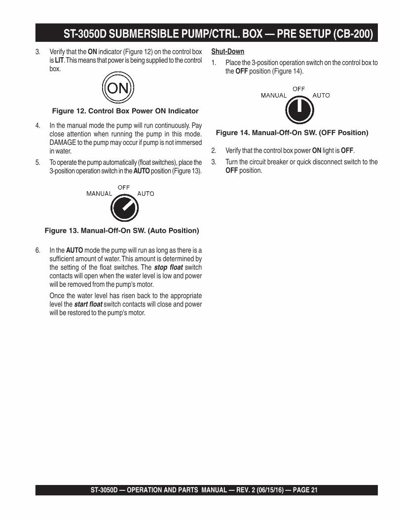
3. Verify that the ON indicator (Figure 12) on the control boxis LIT. This means that power is being supplied to the controlbox.
4. In the manual mode the pump will run continuously. Payclose attention when running the pump in this mode.DAMAGE to the pump may occur if pump is not immersedin water.
5. To operate the pump automatically (float switches), place the3-position operation switch in the AUTO position (Figure 13).
6. In the AUTO mode the pump will run as long as there is asufficient amount of water. This amount is determined bythe setting of the float switches. The stop float switchcontacts will open when the water level is low and powerwill be removed from the pump's motor.
Once the water level has risen back to the appropriatelevel the start float switch contacts will close and powerwill be restored to the pump's motor.
Figure 12. Control Box Power ON Indicator
Figure 13. Manual-Off-On SW. (Auto Position)
Shut-Down1. Place the 3-position operation switch on the control box to
the OFF position (Figure 14).
2. Verify that the control box power ON light is OFF.
3. Turn the circuit breaker or quick disconnect switch to theOFF position.
Figure 14. Manual-Off-On SW. (OFF Position)
ST-3050D SUBMERSIBLE PUMP/CTRL. BOX — PRE SETUP (CB-200)

PAGE 22 — ST-3050D — OPERATION AND PARTS MANUAL — REV. #2 (06/15/16)
ST-3050D SUB. PUMP/CTRL. BOX — INSTALLATION (MCP102/104)
DANGER:
Remember this control box contains hazardous voltages.Disconnect all sources of power before installing or servicing.There exists the possibility of electrocution, electric shock orburn, which can cause severe bodily harm or even death!
Remember the MCP102 Control Box is to be used only for230 VAC 3-phase applications and the MCP 104 Control Boxis for 460 VAC 3-phase applications. Neither control box hasfloat switch capability.
POWER CORD REQUIREMENTS
When routing the three phase power via a power cord to thecontrol box, ALWAYS use the correct wire size. Please referenceTable 3 (Cord Length/Wire Size) to determine the correct wiresize. Incorrect wire size can adversely affect the performance ofthe pump.
CONTROL BOX MOUNTING
Mount the control box in an upright vertical position. Make surethe control box is securely fastened to a flat surface, that is freeof dust, dirt, moisture or any elements that may contaminate orerode the electronic components of the control box.
3-PHASE POWER CORD (INPUT TO BOX) INSTALLATION
1. The three phase input power cord should have four wires.Each wire is color coded. The colors are RED, WHITE,BLACK and GREEN.
2. Remove the 3-phase AC input connector housing from thecontrol box, then route the three phase input power cablethrough the cable gland on the control box. Attach thewires to the terminal block on the electronic overload unitinside the control box as indicated by Table 5 and Figure 15.
3. Tighten the connector housing to ensure a tight fit betweenthe power cord and the connector body. This will preventthe cable from pulling out of the terminal block and alsoprevent moisture from entering the control box.
It is recommended that the power being supplied to the controlbox ALWAYS be connected to a circuit breaker or a quickdisconnect switch. This safety feature allows for quick removalof power from the control box in the event of an emergency.
4. Connect the other end of the 3-phase input power cord tothe voltage source. Remember to provide a means ofdisconnecting the power from the control box (circuit breakeror quick disconnect switch). Also make sure to provide agood earth ground to the control box.
ELECTRONIC OVERLOAD SETTING (230 VAC, 3Ø)
1. Using a small flat-blade screwdriver, set theamperage dial pointer on the electronicoverload unit to 14.2 amps.
ELECTRONIC OVERLOAD SETTING (460 VAC, 3Ø)
1. Using a small flat-blade screwdriver,set theamperage dial pointer on the electronicoverload unit to 7.1 amps.
3-PHASE POWER INSTALLATION (OUTPUT TO PUMP)
1. The three phase output power cord should have four wires.Each wire is color coded. The colors are RED, WHITE,BLACK and GREEN.
2. Remove the 3-phase AC output power connector housingon the control box, then route the three phase output powercable through the cable gland on the control box. Attachthe wires to the AC terminal blocks on the electronicoverload unit as indicated by Table 6 and Figure 15.
14.2
5.1
6.3
7.1
5.1
6.3

ST-3050D — OPERATION AND PARTS MANUAL — REV. 2 (06/15/16) — PAGE 23
Figure 15. MCP102/104 Control Box Configurations
AC POWERINPUT
CONTROL
BOX
TO PUMP
HIGHVOLTAGE
HIGHVOLTAGE
CAUTIONMCP102
MOUNT CONTROLBOX IN AN UPRIGHTVERTICAL POSITION
AS SHOWN.
(230 VAC, 3Ø)
ST-3050D SUB. PUMP/CTRL. BOX — WIRING DIAGRAM (MCP102/104)
CONTROL
BOX
HIGHVOLTAGE
HIGHVOLTAGE
CAUTIONMCP104
TO PUMPAC POWER
INPUT
(460 VAC, 3Ø)
3 PHASEAC POWER
INPUT
GREEN
BLACK RED
WHITE
3 PHASEAC POWER
OUTPUT
EXTERNAL 3-PHASE(230/460 VAC)
POWER SOURCE
CIRCUITBREAKER
REDWHITE
BLACK
L1
L2
L3
GR
EE
N
GROUND
3 PHASEAC INPUT
POWER CABLE
3 PHASEAC OUTPUT
POWER CABLE
ELECTRONICOVERLOAD
UNIT
WARNING
INSTALLATION IS TO BE PREFORMEDONLY BY A LICENSED ELECTRICIAN
OR QUALIFIED PERSONNEL.SUBMERSIBLE
PUMP
ST-3050D
STOP START4
5.1
6.3
TEST
2/T1 4/T2 6/T3
1/L1 3/L2 5/L3
GROUND
GREEN
WHITE
MCP102/MCP104
SET TO14.2 AMPS
TERMINALBLOCK
TERMINALBLOCK
RED BLACK
PAGE 24 — ST-3050D — OPERATION AND PARTS MANUAL — REV. #2 (06/15/16)
ST-3050D SUBMERSIBLE PUMP — OPERATION
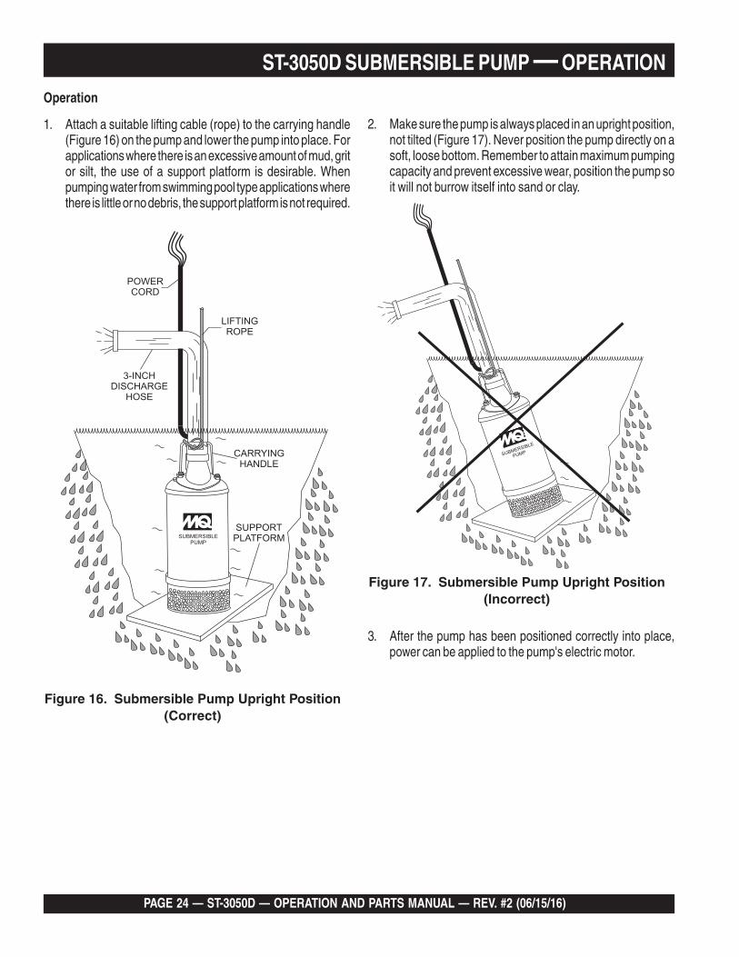
Operation
1. Attach a suitable lifting cable (rope) to the carrying handle(Figure 16) on the pump and lower the pump into place. Forapplications where there is an excessive amount of mud, gritor silt, the use of a support platform is desirable. Whenpumping water from swimming pool type applications wherethere is little or no debris, the support platform is not required.
2. Make sure the pump is always placed in an upright position,not tilted (Figure 17). Never position the pump directly on asoft, loose bottom. Remember to attain maximum pumpingcapacity and prevent excessive wear, position the pump soit will not burrow itself into sand or clay.
SUBMERSIBLEPUMP
LIFTINGROPE
3-INCHDISCHARGE
HOSE
POWERCORD
SUPPORTPLATFORM
CARRYINGHANDLE
Figure 16. Submersible Pump Upright Position(Correct)
Figure 17. Submersible Pump Upright Position(Incorrect)
3. After the pump has been positioned correctly into place,power can be applied to the pump's electric motor.
SUBMERSIBLE
PUMP
ST-3050D — OPERATION AND PARTS MANUAL — REV. 2 (06/15/16) — PAGE 25
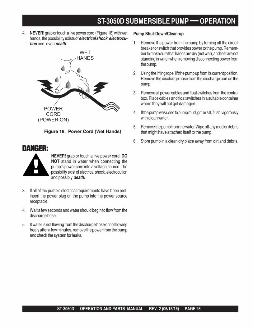
4. NEVER! grab or touch a live power cord (Figure 18) with wethands, the possibility exists of electrical shock, electrocu-tion and even death.
ST-3050D SUBMERSIBLE PUMP — OPERATION
Figure 18. Power Cord (Wet Hands)
DANGER:DANGER:DANGER:DANGER:DANGER:NEVER! grab or touch a live power cord. DONOT stand in water when connecting thepump's power cord into a voltage source. Thepossibility exist of electrical shock, electrocutionand possibly death!
3. If all of the pump's electrical requirements have been met,insert the power plug on the pump into the power sourcereceptacle.
4. Wait a few seconds and water should begin to flow from thedischarge hose.
5. If water is not flowing from the discharge hose or not flowingfreely after a few minutes, remove the power from the pumpand check the system for leaks.
Pump Shut-Down/Clean-up
1. Remove the power from the pump by turning off the circuitbreaker or switch that provides power to the pump. Remem-ber to make sure that hands are dry (not wet), and feet are notstanding in water when removing disconnecting power fromthe pump.
2. Using the lifting rope, lift the pump up from its current position.Remove the discharge hose from the discharge port on thepump.
3. Remove all power cables and float switches from the controlbox. Place cables and float switches in a suitable containerwhere they will not get damaged.
4. If the pump was used to pump mud, grit or silt, flush vigorouslywith clean water.
5. Remove the pump from the water. Wipe off any mud or debristhat might have attached itself to the pump.
6. Store pump in a clean dry place away from dirt and debris.
POWERCORD
(POWER ON)
WETHANDS

PAGE 26 — ST-3050D — OPERATION AND PARTS MANUAL — REV. #2 (06/15/16)
ST-3050D SUBMERSIBLE PUMP — MAINTENANCE
LUBRICATION
To check the oil level of the mechanical seal perform thefollowing:
1. Lay the pump (Figure 19) on its side with the oil plug facingupwards.
2. Remove oil fill plug.
3. Visually inspect oil plug hole to verify that oil cavity is fullenough to cover seal spring. Check every 300 hours, changehydraulic oil every 6 months (1,000 hours) or as needed.
4. While checking the hydraulic oil level, also check thecondition of the hydraulic oil in the seal cavity . Block theopening with a finger and roll pump to one side to drainoil into a small transparent container. If oil is cloudy or haswater in it, drain oil from pump cavity and replace hydrau-lic oil. Check the seal for wear damage.
5. If oil level is low fill with SAE 10 weight non-detergenthydraulic oil (i.e. Shell Turbo 32 or equivalent). Fill oil cavity75% to 85% full (allow air space for expansion). Pump oilcavity capacity is approximately 180 cc.
IMPELLER
1. Make sure the clearance between the impeller and thefriction disk is approximately .012 - .020 inches (.304 - .508mm.)
2. If impeller is defective or badly worn, replace impeller imme-diately.
Figure 19. Checking Hydraulic Oil

ST-3050D — OPERATION AND PARTS MANUAL — REV. 2 (06/15/16) — PAGE 27
ST-3050D SUBMERSIBLE PUMP — TROUBLESHOOTING
GNITOOHSELBUORTPMUP.XELBAT
MOTPMYS MELBORPELBISSOP NOITULOS
tratSoTsliaFpmuP
?spma/egatlovtcerrocnIehtotdeilppusgniebsi)Ø3064/032(egatlovreporptahtkcehCtnerrucfotnuomaetauqedanasierehttahtkcehcoslA.pmup
.rekaerbtiucricecruosrewopkcehC.pmupehtnurot)spma(
?snoitcennoclacirtcelekcehC .drocrewoptcepsni,gniriwkcehcsehctiwstaolfgnisufI
?esufrewopnwolB .esufnwolbfoesuackcehc,esufecalpeR
?dekcolrellepmI rellepmireporpmidnagniggolcrofkcehcdnadrocrewoptcennocsiD.ecivednoitcetorpdaolrevokcehC.pmupgolcnU.ecnaraelc
?sgnidniwrotomteWtsumecnatsisernoitalusnI.noitalusnirotomkcehcotretemitlumesUelbmessasid,wolsiecnatsiserfI.smhoagem51yletamixorppaeb
.mehtyrdotsgnidniwekabdnarotompmup
pmupdnarotomevitcefeD?sgniraeb
ecalpeR.sgniraebecalpernrowfi,raewgniraebevissecxerofkcehC.evitcefedfirotom
lluFrevileDotsliaFpmuPtuptuO
egrahcsiddetcirtserrodetsiwT?esoh
.enilesohmorfgolcevomeR.deknik-nutalfesohyaL
?reniartspmupdeggolC .reniartsnaelC
?egatlovwoL
egatloV.dezigrenesipmupelihwegatlovkcehcotretemtlovaesUnafI.)daoldnadaolon(ecruosrewopkcehC.%01±nihtiwebtsumgniyrrac-tnerrucetauqedasahtierusekam,desusidrocnoisnetxe
.htgnelderiuqerehtrofyticapac
?nrowrellepmI .rellepmiecalpeR
liOlaeSniretaW?laesretawevitcefeD .laesretawecalpeR
?gulPlliFliOesooL .ylerucesnethgiT
0 100 200 300
Performance Curve
Capacity(US.G.P.M)
To
talH
ea
d(F
ee
t)
90
60
30
TOTAL HEAD
CAPACITY
Max 86 ft
Max 264 G.P.MFigure 20.Performance Chart

PAGE 28 — ST-3050D — OPERATION AND PARTS MANUAL — REV. #2 (06/15/16)
EXPLANATION OF CODE IN REMARKS COLUMN
How to read the marks and remarks used in this partsbook.
Items Found In the “Remarks” Column
Serial Numbers-Where indicated, this indicates a serialnumber range (inclusive) where a particular part is used.
Model Number-Where indicated, this shows that thecorresponding part is utilized only with this specific modelnumber or model number variant.
Items Found In the “Items Number” Column
All parts with same symbol in the number column, *, #, +, %, or■, belong to the same assembly or kit.
NOTE
The contents of thisparts catalog aresubject to changewithout notice.
If more than one of the samereference number is listed,the last one listed indicatesnewest (or latest) partavailable.
NOTE

ST-3050D — OPERATION AND PARTS MANUAL — REV. 2 (06/15/16) — PAGE 29
ST-3050D SUBMERSIBLE PUMP 1 TO 3 UNITS1 to 3 Units
Qty. ........ P/N .............................. Description1 ............ 0203050120 ................ AC CORD W/CORD GLAND1 ............ 0203050060 ................ MECHANICAL SEAL1 ............ 0203050081 ................ OIL SEAL1 ............ 0203050047 ................ LINER1 ............ 0203050003 ................ IMPELLER1 ............ 0202020004 ................ IMPELLER NUT2 ............ 0203050214 ................ PACKING1 ............ 0202020157 ................ PACKING1 ............ 0202020435 ................ PACKING1 ............ 0202020435 ................ SPRING WASHER
ST-3050D — SUGGESTED SPARE PARTS
PAGE 30 — ST-3050D — OPERATION AND PARTS MANUAL — REV. #2 (06/15/16)
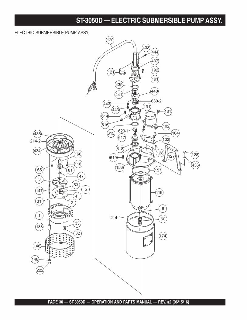
ST-3050D — ELECTRIC SUBMERSIBLE PUMP ASSY.
ELECTRIC SUBMERSIBLE PUMP ASSY.

ST-3050D — OPERATION AND PARTS MANUAL — REV. 2 (06/15/16) — PAGE 31
ELECTRIC SUBMERSIBLE PUMP ASSY.
NO PART NO PART NAME QTY. REMARK1 0203050001 CASING 12 0203050002 FRICTION DISC. 13 0203050003 IMPELLER 14 0202020004 IMPELLER NUT 15 0202020005 SPRING WASHER 16 0203050006 IMPELLER KEY 131 0202020031 STUD BOLT 432 0202020032 NUT 433 0202020033 WASHER 447 0203050047 LINER 153 0202020053 WASHER 160 0203050060 MECHANICAL SEAL 165 0202020065 PLUG 181 0203050081 OIL SEAL 1102 0203050102 DISCHARGE PORT 1103 0203050103 PACKING 1104 0203050104 STUD BOLT 2116 0202020116 BOLT 3119 0203050119 MOTOR ........................................ 1 .................... ST-3050119 0203050D119 MOTOR ........................................ 1 .................... ST-3050D120 0203050120 AC CORD W/CORD GLAND 1121 0202020121 CORD CLAMP 1127 0202020127 CARRYING HANDLE 1128 0202020128 BOLT 2146 0203050146 STRAINER 1147 0203050147 STUD BOLT 4148 0203050148 SPRING WASHER 4156 0203050156 HEAD COVER 1157 0202020157 PACKING 1160 0203050160 SLEEVE 1174 0203050174 OUTER PIPE 1188 0203050188 STRAINER SET PIPE 4191 0202020191 POWER CORD GLAND CASE 1192 0202020192 BOLT 4214-1 0203050214 PACKING 1214-2 0203050214 PACKING 1
ST-3050D — ELECTRIC SUBMERSIBLE PUMP ASSY.

PAGE 32 — ST-3050D — OPERATION AND PARTS MANUAL — REV. #2 (06/15/16)
ST-3050 D— ELECTRIC SUBMERSIBLE PUMP ASSY.

ST-3050D — OPERATION AND PARTS MANUAL — REV. 2 (06/15/16) — PAGE 33
ELECTRIC SUBMERSIBLE PUMP ASSY.
NO PART NO PART NAME QTY. REMARK222 0203050222 NUT 4224 0202020224 PLUG 1431 0203050431 NUT 2434 0203050434 STUFFING BOX 1435 0202020435 PACKING 1436 0202020436 SPRING WASHER 2437 0202020437 CORD GLAND CASE COVER 1438 0202020438 BOLT 3439 0202020439 PACKING 1440 0202020440 CONNECTOR 1441 0202020441 PACKING 1442 0202020442 BOLT 3443 0202020443 WASHER 3444 0202020444 BOLT 2613 0203050D613 CONNECTOR CASE 1 ST-3050D614 0203050D614 BOLT 4 ST-3050D615 0203050D615 PACKING 1 ST-3050D616 0203050D616 PLUG 1 ST-3050D617 0203050D617 GLAND RUBBER 1 ST-3050D618 0203050D618 GLAND METAL 1 ST-3050D619 0203050D619 BOLT 3 ST-3050D620-1 0203050D620A CONNECTOR 1 ST-3050D620-2 0203050D620B CONNECTOR 1 ST-3050D
ST-3050D — ELECTRIC SUBMERSIBLE PUMP ASSY.

PAGE 34 — ST-3050D — OPERATION AND PARTS MANUAL — REV. #2 (06/15/16)
ST-3050D — ELECTRIC MOTOR ASSY.
ELECTRIC MOTOR ASSY.
ST-3050D — OPERATION AND PARTS MANUAL — REV. 2 (06/15/16) — PAGE 35
ST-3050D — ELECTRIC MOTOR ASSY.
ELECTRIC MOTOR ASSY.
NO PART NO PART NAME QTY. REMARK131 0203050131 BOLT 4132 0202020B132 WASHER, LOCK 4268 0203050268 MOTOR A BRACKET 1269 0203050269 MOTOR B BRACKET 1270 0203050270 MOTOR ROTOR 1273 0203050D273 MOTOR STATOR 1322 0202020B322 NUT 4540 0203050540 A PACKING 1541 0203050541 B PACKING 1606 0203050606 A BEARING, MOTOR 1607 0203050607 B BEARING, MOTOR 1608 0202020B608 WASHER, WAVE 1
PAGE 36 — ST-3050D — OPERATION AND PARTS MANUAL — REV. #2 (06/15/16)
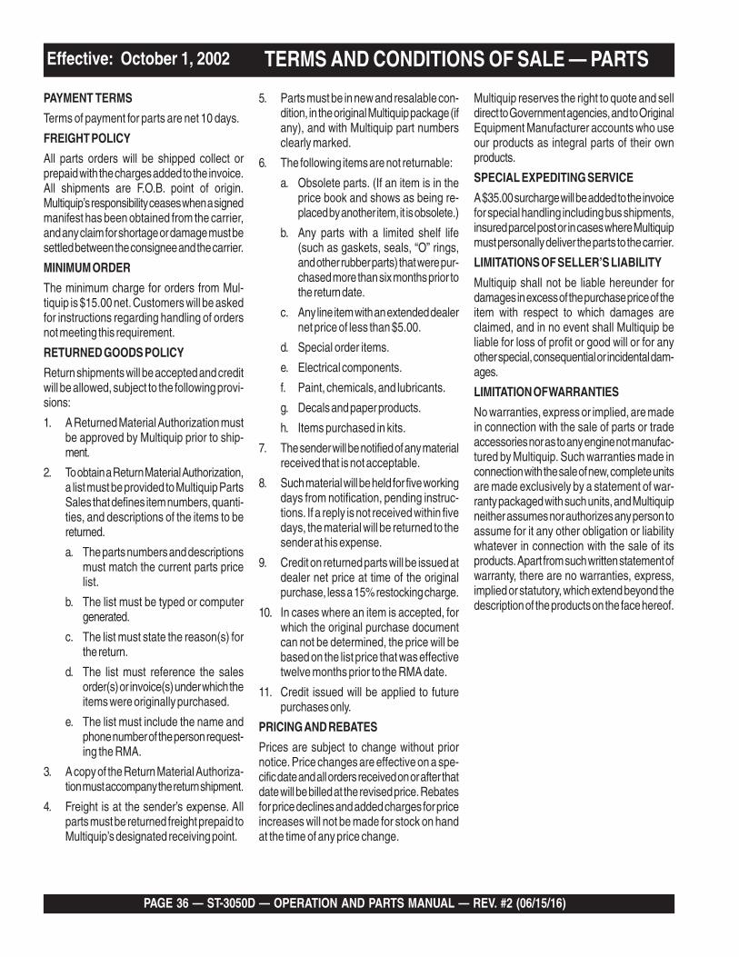
Effective: October 1, 2002 TERMS AND CONDITIONS OF SALE — PARTS
PAYMENT TERMS
Terms of payment for parts are net 10 days.
FREIGHT POLICY
All parts orders will be shipped collect orprepaid with the charges added to the invoice.All shipments are F.O.B. point of origin.Multiquip’s responsibility ceases when a signedmanifest has been obtained from the carrier,and any claim for shortage or damage must besettled between the consignee and the carrier.
MINIMUM ORDER
The minimum charge for orders from Mul-tiquip is $15.00 net. Customers will be askedfor instructions regarding handling of ordersnot meeting this requirement.
RETURNED GOODS POLICY
Return shipments will be accepted and creditwill be allowed, subject to the following provi-sions:
1. A Returned Material Authorization mustbe approved by Multiquip prior to ship-ment.
2. To obtain a Return Material Authorization,a list must be provided to Multiquip PartsSales that defines item numbers, quanti-ties, and descriptions of the items to bereturned.
a. The parts numbers and descriptionsmust match the current parts pricelist.
b. The list must be typed or computergenerated.
c. The list must state the reason(s) forthe return.
d. The list must reference the salesorder(s) or invoice(s) under which theitems were originally purchased.
e. The list must include the name andphone number of the person request-ing the RMA.
3. A copy of the Return Material Authoriza-tion must accompany the return shipment.
4. Freight is at the sender’s expense. Allparts must be returned freight prepaid toMultiquip’s designated receiving point.
5. Parts must be in new and resalable con-dition, in the original Multiquip package (ifany), and with Multiquip part numbersclearly marked.
6. The following items are not returnable:
a. Obsolete parts. (If an item is in theprice book and shows as being re-placed by another item, it is obsolete.)
b. Any parts with a limited shelf life(such as gaskets, seals, “O” rings,and other rubber parts) that were pur-chased more than six months prior tothe return date.
c. Any line item with an extended dealernet price of less than $5.00.
d. Special order items.
e. Electrical components.
f. Paint, chemicals, and lubricants.
g. Decals and paper products.
h. Items purchased in kits.
7. The sender will be notified of any materialreceived that is not acceptable.
8. Such material will be held for five workingdays from notification, pending instruc-tions. If a reply is not received within fivedays, the material will be returned to thesender at his expense.
9. Credit on returned parts will be issued atdealer net price at time of the originalpurchase, less a 15% restocking charge.
10. In cases where an item is accepted, forwhich the original purchase documentcan not be determined, the price will bebased on the list price that was effectivetwelve months prior to the RMA date.
11. Credit issued will be applied to futurepurchases only.
PRICING AND REBATES
Prices are subject to change without priornotice. Price changes are effective on a spe-cific date and all orders received on or after thatdate will be billed at the revised price. Rebatesfor price declines and added charges for priceincreases will not be made for stock on handat the time of any price change.
Multiquip reserves the right to quote and selldirect to Government agencies, and to OriginalEquipment Manufacturer accounts who useour products as integral parts of their ownproducts.
SPECIAL EXPEDITING SERVICE
A $35.00 surcharge will be added to the invoicefor special handling including bus shipments,insured parcel post or in cases where Multiquipmust personally deliver the parts to the carrier.
LIMITATIONS OF SELLER’S LIABILITY
Multiquip shall not be liable hereunder fordamages in excess of the purchase price of theitem with respect to which damages areclaimed, and in no event shall Multiquip beliable for loss of profit or good will or for anyother special, consequential or incidental dam-ages.
LIMITATION OF WARRANTIES
No warranties, express or implied, are madein connection with the sale of parts or tradeaccessories nor as to any engine not manufac-tured by Multiquip. Such warranties made inconnection with the sale of new, complete unitsare made exclusively by a statement of war-ranty packaged with such units, and Multiquipneither assumes nor authorizes any person toassume for it any other obligation or liabilitywhatever in connection with the sale of itsproducts. Apart from such written statement ofwarranty, there are no warranties, express,implied or statutory, which extend beyond thedescription of the products on the face hereof.

ST-3050D — OPERATION AND PARTS MANUAL — REV. 2 (06/15/16) — PAGE 37
NOTE PAGE

OPERATION AND PARTS
Your Local Dealer is:
HERE’S HOW TO GET HELPPLEASE HAVE THE MODEL AND SERIAL
NUMBER ON-HAND WHEN CALLING
© COPYRIGHT 2016, MULTIQUIP INC.
Multiquip Inc , the MQ logo are registered trademarks of Multiquip Inc. and may not be used, reproduced, or altered without written permission. All other trademarks are the propertyof their respective owners and used with permission.
This manual MUST accompany the equipment at all times. This manual is considered a permanent part of the equipment and should remain with the unit if resold.
The information and specifi cations included in this publication were in effect at the time of approval for printing. Illustrations, descriptions, references and technical data contained inthis manual are for guidance only and may not be considered as binding. Multiquip Inc. reserves the right to discontinue or change specifi cations, design or the information publishedin this publication at any time without notice and without incurring any obligations.
UNITED STATESMultiquip Corporate Office MQ Parts Department
18910 Wilmington Ave.Carson, CA 90746 Contact: [email protected]
Tel. (800) 421-1244Fax (310) 537-3927
800-427-1244310-537-3700
Fax: 800-672-7877Fax: 310-637-3284
Service Department Warranty Department
800-421-1244310-537-3700
Fax: 310-537-4259 800-421-1244310-537-3700
Fax: 310-943-2249
Technical Assistance
800-478-1244 Fax: 310-943-2238
CANADA UNITED KINGDOM
Multiquip Multiquip (UK) Limited Head Office
4110 Industriel Boul.Laval, Quebec, Canada H7L 6V3Contact: [email protected]
Tel: (450) 625-2244 Tel: (877) 963-4411Fax: (450) 625-8664
Unit 2, Northpoint Industrial Estate, Globe Lane,Dukinfield, Cheshire SK16 4UJContact: [email protected]
Tel: 0161 339 2223 Fax: 0161 339 3226