
Model Specification: CHANCE COMPANY Helical Screw ... HelicalScrewF… · 1 Model Specification:...
28
1 Model Specification: CHANCE ® COMPANY Helical Screw Foundations for Structural Support Preface Types of Specifications The three types of specifications that are used for HELICAL SCREW FOUNDATION (HSF) projects are: Open Specifications: The Contractor is given the responsibility for the scope and design of the HSF installation. In addition, the construction, capacity, and performance of the HSF are the sole responsibility of the Contractor. This specification assumes that the Owner or Designer has provided the required structural loads. This specification type is most common for securing bids on temporary projects, and is not recommended for permanent applications. Performance Specifications: The Contractor is given the responsibility for certain design and/or construction procedures, but must demonstrate to the Owner through testing and/or mutually agreed upon acceptance criteria that the production helical screw foundations meet or exceed the specified performance parameters. This specification assumes that the location and the required loads of the HSF have been specified. The Contractor and Owner share the responsibility for the work. Prescriptive Specifications: The Owner has the sole responsibility for the scope and design of the HSF installation and specifies the procedures that must be followed. Prescriptive specifications mandate the Owner to be responsible for the proper performance of the helical screw foundations. The Contractor is responsible for fulfilling the obligations/details as specified in the construction documents. ____________________________________________________________________________________ Performance specifications are the most common and allow Contractors to use their unique installation methods and experience for any given site conditions. Owners receive the benefit of value engineering, which can result in lower costs. The Owner, Designer, and Contractor will be jointly responsible for the design, installation, acceptance, and performance of HSFs. The installation of an HSF requires specialized equipment, techniques, and trained work crews. Every detail of the work cannot be specified, and every potential problem cannot be anticipated. Therefore, a contractor trained in the proper methods of design and installation of helical screw foundations must be selected. A list of the major tasks to be performed on an HSF project is shown in Table-1 of the Model Specifications. The Owner or his representative should select the type of specification and procurement method. The responsible party for each task must be identified and mutually agreed upon at the earliest point in the contracting process. The completed Table-1 should be included in the construction documents.The process of continuous communication between all the parties involved is essential to achieve a satisfactory result. Clear communication and close cooperation are particularly important in the start-up phase and in testing. In addition, a timely preparation and review of all submittals is critical. This model specification can be adapted to each of the three types of specifications. However, it is primarily written for the performance type. The identity of the Contractor and the Owner is always well defined, unlike that of the Designer or Engineer . For example, the Engineer may be an employee(s) of the Contractor, or a third party consultant hired to secure a lower cost alternative during the bidding process. In contrast, the Engineer may be the Owner, an employee(s) of the Owner, or a representative hired by the Owner. It is recommended that the Engineer be a third party agency employed by the Owner to serve in the owner s best interests during the various stages of the contract.
Transcript of Model Specification: CHANCE COMPANY Helical Screw ... HelicalScrewF… · 1 Model Specification:...

1
Model Specification:CHANCE® COMPANY Helical Screw Foundationsfor Structural Support
PrefaceTypes of SpecificationsThe three types of specifications that are used for HELICAL SCREW FOUNDATION (HSF) projects are:
Open Specifications: The Contractor is given the responsibility for the scope and design of the HSFinstallation. In addition, the construction, capacity, and performance of the HSF are the sole responsibilityof the Contractor. This specification assumes that the Owner or Designer has provided the requiredstructural loads. This specification type is most common for securing bids on temporary projects, and isnot recommended for permanent applications.
Performance Specifications: The Contractor is given the responsibility for certain design and/orconstruction procedures, but must demonstrate to the Owner through testing and/or mutually agreed uponacceptance criteria that the production helical screw foundations meet or exceed the specified performanceparameters. This specification assumes that the location and the required loads of the HSF have beenspecified. The Contractor and Owner share the responsibility for the work.
Prescriptive Specifications: The Owner has the sole responsibility for the scope and design of the HSFinstallation and specifies the procedures that must be followed. Prescriptive specifications mandate theOwner to be responsible for the proper performance of the helical screw foundations. The Contractor isresponsible for fulfilling the obligations/details as specified in the construction documents.____________________________________________________________________________________
Performance specifications are the most common and allow Contractors to use their unique installationmethods and experience for any given site conditions. Owners receive the benefit of value engineering,which can result in lower costs.
The Owner, Designer, and Contractor will be jointly responsible for the design, installation, acceptance,and performance of HSFs. The installation of an HSF requires specialized equipment, techniques, andtrained work crews. Every detail of the work cannot be specified, and every potential problem cannot beanticipated. Therefore, a contractor trained in the proper methods of design and installation of helicalscrew foundations must be selected.
A list of the major tasks to be performed on an HSF project is shown in Table-1 of the ModelSpecifications. The Owner or his representative should select the type of specification and procurementmethod. The responsible party for each task must be identified and mutually agreed upon at the earliestpoint in the contracting process. The completed Table-1 should be included in the constructiondocuments.The process of continuous communication between all the parties involved is essential toachieve a satisfactory result. Clear communication and close cooperation are particularly important in thestart-up phase and in testing. In addition, a timely preparation and review of all submittals is critical.
This model specification can be adapted to each of the three types of specifications. However, it isprimarily written for the performance type. The identity of the Contractor and the Owner is alwayswell defined, unlike that of the Designer or Engineer . For example, the Engineer may be anemployee(s) of the Contractor, or a third party consultant hired to secure a lower cost alternative during thebidding process. In contrast, the Engineer may be the Owner, an employee(s) of the Owner, or arepresentative hired by the Owner. It is recommended that the Engineer be a third party agency employedby the Owner to serve in the owner s best interests during the various stages of the contract.
2
For purposes of this Model Specification, the subject is a high capacity HELICAL SCREWFOUNDATION manufactured by Hubbell Power Systems/A.B. Chance Company. At present, maximumworking or design loads range between 12.5 and 50 tons. The HSF consists of one or more helical bearingplates attached at the tip of a high strength central steel shaft. The central steel shaft consists of either asolid square shaft of various sizes, or hollow pipe shaft of various diameters and wall thickness. The steelshafts are typically 11/2" to 8" in diameter and will accept load directly axially and/or laterally to providestructural support.
It is suggested that the specification writer accurately andcompletely modify this model to suit his/her particular case.
Items in italics as such may be considered as Commentary and as such may be deleted or retained tosuit the needs of the specification writer.____________________________________________________________________________________

3
The following is list of general references that will provide additional background to HELICAL SCREWFOUNDATION technology:
A.B. Chance Company, Helical Pier Foundation Systems, Technical Manual, Bulletin 01-9601, Copyright2000 Hubbell, 210 North Allen St., Centralia, MO 65240
BOCA Research Report 94-27 , Copyright 1996, BOCA Evaluation Services, Inc., Country Club Hills,IL 60478
Goen, J. Lee, Compression Load on Helical Pier Foundation Systems Anchors — Design and Construction,Bulletin 01-9304, Copyright 1998 Hubbell/Chance, 210 North Allen St., Centralia, MO 65240
Hargrave, R. L. and Thorsten, R. E., 1992. Helical Piers in Expansive Soils of Dallas, Texas. Proceedings7th International Conference on Expansive Soils, Session 24, Bulletin 01-9311, Copyright 1993 A.B.Chance, 210 North Allen St., Centralia, MO 65240
Hoyt, R.M. and Clemence, S.P., 1989. Uplift Capacity of Helical Anchors in Soil. Proceedings of the 12thInternational Conference on Soil Mechanics and Foundation Engineering, Vol. 2, pp. 1019-1022.
ICBO Evaluation Report - ER-5110 , Copyright 2001, ICBO Evaluation Service, Inc., Whittier, CA 90601
Pack, J. S., 2000. Design of Helical Piles for Heavily Loaded Structures. New Technological and DesignDevelopments in Deep Foundations, ASCE Geotechnical Special Publication, pp. 353- 367.
SBCCI Report No. 9504B , Copyright 1999, SBCCI Public Safety Testing and Evaluation Services Inc.,Birmingham, AL 35213
Seider, Gary L., Versatile Steel Screw Anchors , Structural Engineer Magazine, March 2000; Volume 1,Number 2, ppgs. 42-46.

4
1. GENERAL1.1 Purpose of Specification1.2 Scope of Work1.3 Qualifications of the Contractor1.4 Related Project Specifications1.5 Definitions1.6 Allowable Tolerances1.7 Quality Assurance1.8 Design Criteria1.9 Ground Conditions
2. REFERENCED CODES AND STANDARDS2.1 American Society for Testing and Materials2.2 American Welding Society2.3 American Society of Civil Engineers2.4 Deep Foundations Institute2.5 Post Tensioning Institute2.6 Society of Automotive Engineers
3. SUBMITTALS3.1 Construction Submittals3.2 Installation Records3.3 Test Reports3.4 Closeout Submittals
4. PRODUCTS AND MATERIALS4.1 Central Steel Shaft4.2 Helical Bearing Plate4.3 Bolts4.4 Couplings4.5 Plates, Shapes or Pier Caps4.6 Corrosion Protection (Optional)
5. EXECUTION5.1 Site Conditions5.2 Installation Equipment5.3 Installation Tooling5.4 Installation Procedures5.5 Termination Criteria
6. HELICAL SCREW FOUNDATION TESTS6.1 Pre-Production Tests (Optional)6.2 Load Test Equipment6.3 Testing Program6.4 Acceptance Criteria6.5 Production Helical Screw Foundation Testing6.6 Lateral Testing
7. MEASUREMENT AND PAYMENT
APPENDICESMechanical Strength Ratings, Helical Screw FoundationsGuidance of Ground Aggressiveness Classification
Model SpecificationTable of Contents:

5
Model Specification:CHANCE® HELICAL SCREW FOUNDATIONS
1. GENERAL
1.1 Purpose of Specification
The purpose of this specification is to detail the furnishing of all designs, materials, tools, equipment, laborand supervision, and installation techniques necessary to install HELICAL SCREW FOUNDATIONS asdetailed on the drawings, including connection details. This shall include provisions for load testing thatmay be part of the scope of work.
Specifier Note: This specification may require modification to account for unusual and/or unforeseen siteand subsurface conditions and the particular circumstances of the project.
1.2 Scope of Work
This work consists of furnishing all necessary engineering and design services (if required), supervision,labor, tools, materials, and equipment to perform all work necessary to install the HELICAL SCREWFOUNDATIONS, at (location, City, State/Province) for (Company, State or Private Authority) per thespecifications described herein, and as shown on the drawings. The Contractor shall install a helical screwfoundation that will develop the load capacities as detailed on the drawings. This may also includeprovisions for load testing to verify helical screw foundation capacity and deflection, if part of the scope ofwork. The responsibilities and duties of the respective parties for this project are summarized in Table-1.
6
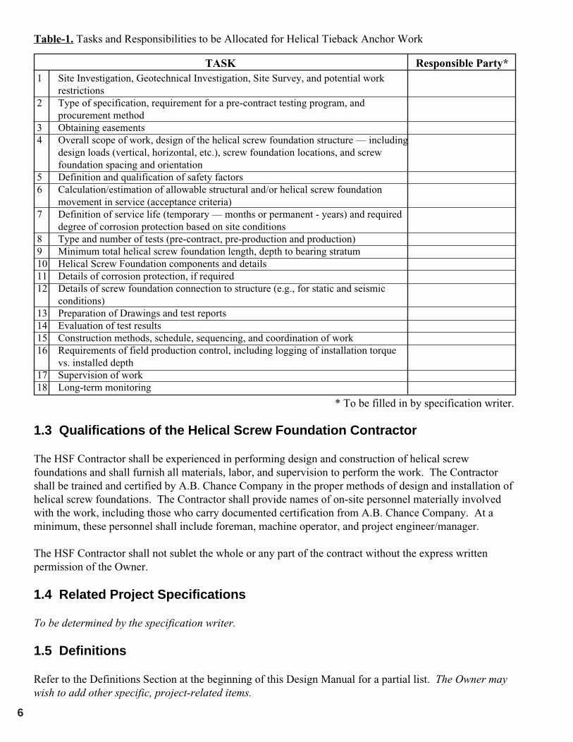
TASK Responsible Party*
* To be filled in by specification writer.
1 Site Investigation, Geotechnical Investigation, Site Survey, and potential workrestrictions
2 Type of specification, requirement for a pre-contract testing program, andprocurement method
3 Obtaining easements4 Overall scope of work, design of the helical screw foundation structure — including
design loads (vertical, horizontal, etc.), screw foundation locations, and screwfoundation spacing and orientation
5 Definition and qualification of safety factors6 Calculation/estimation of allowable structural and/or helical screw foundation
movement in service (acceptance criteria)7 Definition of service life (temporary — months or permanent - years) and required
degree of corrosion protection based on site conditions8 Type and number of tests (pre-contract, pre-production and production)9 Minimum total helical screw foundation length, depth to bearing stratum10 Helical Screw Foundation components and details11 Details of corrosion protection, if required12 Details of screw foundation connection to structure (e.g., for static and seismic
conditions)13 Preparation of Drawings and test reports14 Evaluation of test results15 Construction methods, schedule, sequencing, and coordination of work16 Requirements of field production control, including logging of installation torque
vs. installed depth17 Supervision of work18 Long-term monitoring
Table-1. Tasks and Responsibilities to be Allocated for Helical Tieback Anchor Work
1.3 Qualifications of the Helical Screw Foundation Contractor
The HSF Contractor shall be experienced in performing design and construction of helical screwfoundations and shall furnish all materials, labor, and supervision to perform the work. The Contractorshall be trained and certified by A.B. Chance Company in the proper methods of design and installation ofhelical screw foundations. The Contractor shall provide names of on-site personnel materially involvedwith the work, including those who carry documented certification from A.B. Chance Company. At aminimum, these personnel shall include foreman, machine operator, and project engineer/manager.
The HSF Contractor shall not sublet the whole or any part of the contract without the express writtenpermission of the Owner.
1.4 Related Project Specifications
To be determined by the specification writer.
1.5 Definitions
Refer to the Definitions Section at the beginning of this Design Manual for a partial list. The Owner maywish to add other specific, project-related items.

7
1.6 Allowable Tolerances
The tolerances quoted in this section are suggested maximums. The actual values established for aparticular project will depend on the structural application.
1.6.1 Centerline of helical screw foundations shall not be more than 3 inches from indicated planlocation.
1.6.2 Helical screw foundation plumbness shall be within 2° of design alignment.
1.6.3 Top elevation of helical screw foundation shall be within +1 inch to —2 inches of the design verticalelevation.
1.7 Quality Assurance
1.7.1 Helical screw foundations shall be installed by authorized A.B. Chance Company certifiedContractor. These Contractors shall have satisfied the certification requirements relative to thetechnical aspects of the product and installation procedures as therein specified. Certificationdocuments shall be provided upon request to the Owner or their representative.
1.7.2 The Contractor shall employ an adequate number of skilled workers who are experienced in thenecessary crafts and who are familiar with the specified requirements and methods needed forproper performance of the work of this specification.
1.7.3 All HSFs shall be installed in the presence of a designated representative of the Owner unless saidrepresentative informs the Contractor otherwise. The designated representative shall have the rightto access to any and all field installation records and test reports.
1.7.4 Screw foundation components as specified therein shall be manufactured by a facility whosequality systems comply with ISO (International Organization of Standards) 9001 requirements.Certificates of Registration denoting ISO Standards Number shall be presented upon request to theOwner or their representative.
1.7.5 Hubbell Power Systems/A.B. Chance Company provides a standard one-year warranty onmaterials and workmanship of the product. Any additional warranty provided by the Contractorshall be issued as an addendum to this specification.
1.7.6 Design of helical screw foundations shall be performed by an entity as required in accordance withexisting local code requirements or established local practices. This design work may beperformed by a licensed professional engineer, a certified A.B. Chance certified Contractor, ordesigner depending upon local requirements or practices.
1.8 Design Criteria
1.8.1 Helical screw foundations shall be designed to meet the specified loads and acceptance criteria asshown on the drawings. The calculations and drawings required from the Contractor or Engineershall be submitted to the Owner for review and acceptance in accordance to Section 3.1Construction Submittals .

8
1.8.2 The allowable working load on the helical screw foundations shall not exceed the following values:
1.8.2.1 For compression loads:
Pallowc = 0.4 * fyshaft * Ashaft
Where: Pallowc = allowable working load in compression (kip)fyshaft = minimum yield strength of central steel shaft (ksi)Ashaft = area of central steel shaft (with corrosion allowance if required) (in.2)
The minimum yield strength of the central steel shaft is as follows:Type SS5: 70 ksi; Type SS150, SS175, SS200, SS225: 90 ksi; Type HS: 50 ksi.
These allowable working loads may be reduced by the allowable load capacity per helix plate(s). Itis recommended to use the allowable helix capacities per screw pier type as published by A.B.Chance Company (shown in Table-1 of the Appendix).
1.8.2.2 For tension loads:
Pallowt = Sut / FS
Where: Pallowt = allowable working load in tension (kip)Sut = Min. ultimate tensile strength of central steel shaft segment (at coupling joint) (kip)FS = factor of safety suitable for application, i.e. temporary or permanent structures
For permanent applications, it is recommended to use a factor of safety of two (2). For temporaryapplications, factor of safety typically ranges between 1.25 and 1.5.
It is recommended to use the minimum ultimate tensile strengths as published by A.B. ChanceCompany (shown in Table-1 of the Appendix). The ultimate tensile strength may be reduced by theultimate capacity per helix plate(s) — depending on the number of helix plates specified and type ofshaft family used. The ultimate tensile strength may also be reduced by the torque limited ultimatecapacity — depending on the type of shaft family used.
1.8.3 The ultimate structural capacity shall be determined as:
1.8.3.1 For compression loads:
Pultc = fyshaft * Ashaft
Where:Pultc = ultimate structural capacity in compression (kip)fyshaft = minimum yield strength of central steel shaft (ksi)Ashaft = area of central steel shaft (with corrosion allowance if required) (in.2)
The minimum yield strength of the central steel shaft is as follows:Type SS5: 70 ksi; Type SS150, SS175, SS200, SS225: 90 ksi; Type HS: 50 ksi.

9
The ultimate structural capacity may be reduced by the ultimate load capacity per helix plate(s). Itis recommended to use the ultimate helix capacities per screw pier type as published by A.B. ChanceCompany (shown in Table-1 of the Appendix).
1.8.3.2 For tension loads:
Pultt = Sut
Where:Pultt = Ultimate structural capacity in tension (kip)Sut = Minimum ultimate tensile strength of central steel shaft (kip)
It is recommended to use the minimum ultimate tensile strengths as published by A.B. ChanceCompany (shown in Table-1 of the Appendix). The ultimate tensile strength may be reduced by theultimate capacity per helix plate(s) — depending on the number of helix plates specified and type ofshaft family used. The ultimate tensile strength may also be reduced by the torque limited ultimatecapacity — depending on the type of shaft family used.
1.8.4 Helical screw foundation capacity in soil shall not be relied upon from the following soil layers asdefined in the geotechnical reports:
________________________________________________________________________________________________________________________________________________________________
The overall length and installed torque of a HSF shall be specified such that the required in-soilcapacity is developed by end-bearing on the helix plate(s) in an appropriate strata(s).
It is recommended that the theoretical end-bearing capacity of the helix plates be determined usingHeliCAP“ Engineering Software or equal commercially available software. The required soilparameters (c, φ, γ, or N-values) for use with HeliCAP™ or equal shall be provided in thegeotechnical reports. The Owner shall determine the allowable response to axial loads.
Helical screw foundations are not suited for solid, competent rock, but the helix plates canpenetrate into dense bearing soils. It is recommended that HSFs be installed to a specifiedminimum torque and depth to ensure the helical plates are terminated in bearing soils.Appropriate and repeatable installation techniques and helical screw foundation terminationcriteria must be identified and verified in the field.
1.8.5 Lateral Load and Bending: Where helical screw foundations are subjected to lateral or base shearloads as indicated on the plans, the bending moment from said loads shall be determined usinglateral load analysis program such as LPILE or equal commercially available software. Therequired soil parameters (c, φ, γ, and ks) for use with LPILE or equal shall be provided in thegeotechnical reports. The Owner shall determine the allowable response to lateral loads. Thecombined bending and axial load factor of safety of the HSF shall be as determined by the Owner.
Helical screw foundations are slender foundation elements, i.e. the shafts range from 11/2" to 31/2"in diameter. As such, vertically installed HSFs generally require enlarged shaft sections or pilecaps to adequately resist lateral load. The lateral load analysis as detailed in Section 1.8.5 of the

10
specification can be used to determine the required diameter and length of the enlarged shaftsection or pile cap.
It is recommended to list below each load combination and required factor of safety for thisspecific project.
1.8.6 Critical Buckling Load: Where helical screw foundations are installed into low strength soil, thecritical buckling load shall be determined using lateral load analysis program such as LPILE orequal commercially available software, or various other methods. The required soil parameters (c,φ, γ, and ks) for use with LPILE or equal shall be provided in the geotechnical reports.
Research shows that buckling, either elastic or nonelastic, is of practical concern only for longHSF shafts in the softest soils. This is in agreement with past findings regarding conventional pilefoundations.
1.8.7 Expansive Soils: HSFs used in areas where expansive soils are present may require the use ofspecial construction methods to mitigate possible shrink/swell effects. HSF shafts should beisolated from the concrete footing if said footing is in contact with the expansive soil.
1.8.8 Down-Drag/Negative Skin Friction: Type SS and Type HS HSFs are slender shaft foundationelements and are not practically affected by down-drag/negative skin friction. If HSFs with centralsteel shafts >4" in diameter are used in areas where compressible or decomposing soils overliebearing stratum, or where expansive or frozen soils can cause pile jacking, HSF shafts should beprovided with a no-bond zone along a specified length to prevent load transfer that may adverselyaffect pile capacity. Alternately, HSFs can be provided with sufficient axial load capacity to resistdown drag/negative skin friction forces.
1.8.9 The HSF attachment (pile cap) shall distribute the design load (DL) to the concrete foundation suchthat the concrete bearing stress does not exceed those in the ACI Building Code and the stresses inthe steel plates/welds does not exceed AISC allowable stresses for steel members.
1.8.10 Corrosion Protection
This section is optional (see below). Provisions of this section and Section 4.6 below may not berequired in the Specification. If this section is not used, then Section 4.6 should likewise bedeleted. The degree and extent of corrosion protection must be specified by the Owner (Table-1).
Corrosion protection is a function of structure type, service life, and the overall aggressiveness ofthe project soils. The need for corrosion protection of helical screw foundations must be carefullydetermined and specified as necessary.
Corrosion resistant coatings (i.e. epoxy, plastic sheath) on the lead section are impractical due toabrasive action wearing off the coating as the soil flows over the helix plates and around thecentral steel shaft. Hot dip galvanization is the only practical means to provide a corrosionresistant coating capable of withstanding the rigors of installation. Extension sections aretypically hot-dip galvanized, but other coatings can be specified.
The following requirements are typical. The specifier should review and edit as appropriate forthe project.

11
NON-AGGRESSIVE
a. Bare steelOR
b. GalvanizationOR
c. Minimum 1/8"corrosion loss onoutside
a. Bare steelOR
b. GalvanizationOR
c. Epoxy coating
g. Bare steelOR
h. GalvanizationOR
i. Epoxy coating
Structure Type: _________________________ (e.g. temporary, permanent) with a temporarystructure being defined within a specified time frame (i.e. months rather than years). In general,permanent structures have a service life greater than 24 months.
Temporary structures do not require corrosion protection.
Service Life: ____________________________(years) a typical service life of 50 years should beused unless otherwise specified. If the service life of a temporary helical screw foundation is likelyto be extended due to construction delays, it should be considered permanent.
For a service life of less than 20 years in non-aggressive soil, corrosion protection is notrecommended.
Corrosion protection requirements for the various helical screw foundation elements shall beprovided meeting the requirements of Table-2 for:
Soil: ____________________________________ Aggressive or Non-Aggressive with optionallocation and elevation limits defined by the Specifier.
For guidance on aggressiveness classification, see Table-2 in the Appendix. It is recommended toretain the services of a corrosion design professional for very aggressive soils.
CORROSION PROTECTION
LOADING
Table-2.
TENSION COMPRESSION
SOIL
CENTRAL STEELSHAFT(Lead Section)
CENTRAL STEELSHAFT(Extension Section)
STEEL PILE CAP
AGGRESSIVE1
a. GalvanizationOR
b. Minimum 1/8"corrosion loss onoutside
a. GalvanizationOR
b. Epoxy coatingOR
c. a. or b. + Groutcover2
The Specifier mayelect to use a groutcase.
a. GalvanizationOR
b. Epoxy coating
NON-AGGRESSIVE
a. Bare steelOR
b. GalvanizationOR
c. Minimum 1/8"corrosion loss onoutside
a. Bare steelOR
b. GalvanizationOR
c. Epoxy coating
d. Bare steelOR
e. GalvanizationOR
f. Epoxy coating
AGGRESSIVE1
a. GalvanizationOR
b. Minimum 1/8"corrosion loss onoutside
a. GalvanizationOR
b. Epoxy coatingOR
c. a. or b. + Groutcover2
The Specifier mayelect to use a groutcase.
c. GalvanizationOR
d. Epoxy coating

12
NOTES:Lettered items are options.For guidance on aggressiveness classification, see Table-2 of the Appendix.1. Corrosion protection shall extend 15’-0 below corrosive material.2. Minimum 1" in soil. If protective coatings (galvanization, epoxy) are provided in compression,
minimum cover may be 0.25" in soil. Grout column can be installed using the patented HELICALPULLDOWN¤ Micropile method.
The most critical area to protect from corrosion is at or near the ground line — if the surficial soilshave been disturbed. Undisturbed soils are deficient in oxygen a few feet below ground line orbelow the water table zone. Undisturbed soils typically result in steel piling not being appreciablyaffected by corrosion.
1.9. Ground Conditions
The Geotechnical Report, including logs of soil borings as shown on the boring location plan, shall beconsidered to be representative of the in-situ subsurface conditions likely to be encountered on the projectsite. Said Geotechnical Report shall be the used as the basis for helical screw foundation design usinggenerally accepted engineering judgement and methods.
If soil borings are not available, it is suggested to install a helical screw foundation at various locationson the project site. Using the well-known installed torque vs. capacity attribute of screw anchors, apresumptive soil profile can be generated.
The Geotechnical Report shall be provided for purposes of bidding. If during helical screw foundationinstallation, subsurface conditions of a type and location are encountered of a frequency that were notreported, inferred and/or expected at the time of preparation of the bid, the additional costs required toovercome such conditions shall be considered as extras to be paid for.
All available information related to subsurface and general site conditions should be made available to allbidders at the time of bid preparation. It is not reasonable to expect bidders to conduct supplemental siteinvestigations at their own risk and cost prior to bidding, unless the specific contract requirements call forit (Table-1) and provide for appropriate compensation. A mandatory site visit and pre-bid meeting shouldbe held so that the details of the project and the specifications can be thoroughly discussed. These stepswill help avoid technical and contractual problems developing during the execution of the work, and willhelp all parties manage their respective risk.
2 REFERENCED CODES AND STANDARDS
Standards listed by reference, including revisions by issuing authority, form a part of this specificationsection to the extent indicated. Standards listed are identified by issuing authority, authority abbreviation,designation number, title, or other designation established by issuing authority. Standards subsequentlyreferenced herein are referred to by issuing authority abbreviation and standard designation. In case ofconflict, the particular requirements of this specification shall prevail. The latest publication as of theissue of this specification shall govern, unless indicated otherwise.
2.1 American Society for Testing and Materials (ASTM):
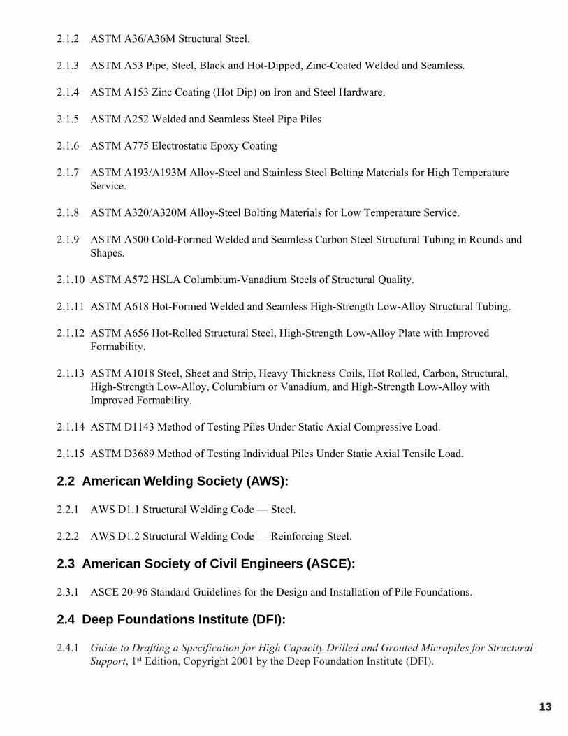
2.1.1 ASTM A29/A29M Steel Bars, Carbon and Alloy, Hot-Wrought and Cold Finished.
13
2.1.2 ASTM A36/A36M Structural Steel.
2.1.3 ASTM A53 Pipe, Steel, Black and Hot-Dipped, Zinc-Coated Welded and Seamless.
2.1.4 ASTM A153 Zinc Coating (Hot Dip) on Iron and Steel Hardware.
2.1.5 ASTM A252 Welded and Seamless Steel Pipe Piles.
2.1.6 ASTM A775 Electrostatic Epoxy Coating
2.1.7 ASTM A193/A193M Alloy-Steel and Stainless Steel Bolting Materials for High TemperatureService.
2.1.8 ASTM A320/A320M Alloy-Steel Bolting Materials for Low Temperature Service.
2.1.9 ASTM A500 Cold-Formed Welded and Seamless Carbon Steel Structural Tubing in Rounds andShapes.
2.1.10 ASTM A572 HSLA Columbium-Vanadium Steels of Structural Quality.
2.1.11 ASTM A618 Hot-Formed Welded and Seamless High-Strength Low-Alloy Structural Tubing.
2.1.12 ASTM A656 Hot-Rolled Structural Steel, High-Strength Low-Alloy Plate with ImprovedFormability.
2.1.13 ASTM A1018 Steel, Sheet and Strip, Heavy Thickness Coils, Hot Rolled, Carbon, Structural,High-Strength Low-Alloy, Columbium or Vanadium, and High-Strength Low-Alloy withImproved Formability.
2.1.14 ASTM D1143 Method of Testing Piles Under Static Axial Compressive Load.
2.1.15 ASTM D3689 Method of Testing Individual Piles Under Static Axial Tensile Load.
2.2 American Welding Society (AWS):
2.2.1 AWS D1.1 Structural Welding Code — Steel.
2.2.2 AWS D1.2 Structural Welding Code — Reinforcing Steel.
2.3 American Society of Civil Engineers (ASCE):
2.3.1 ASCE 20-96 Standard Guidelines for the Design and Installation of Pile Foundations.
2.4 Deep Foundations Institute (DFI):
2.4.1 Guide to Drafting a Specification for High Capacity Drilled and Grouted Micropiles for StructuralSupport, 1st Edition, Copyright 2001 by the Deep Foundation Institute (DFI).

14
2.5 Post Tensioning Institute (PTI)
2.5.1 Recommendations for Prestressed Rock and Soil Anchors, Third Edition, Copyright 1996 By thePost-Tensioning Institute.
2.6 Society of Automotive Engineers (SAE):
2.6.1 SAE J429 Mechanical and Material Requirements for Externally Threaded Fasteners.
3 SUBMITTALS
3.1 Construction Submittals
3.1.1 The Contractor or Engineer shall prepare and submit to the Owner, for review and approval,working drawings and design calculations for the helical screw foundations intended for use atleast 14 calendar days prior to planned start of construction (but note also Paragraph 3.1.8). Allsubmittals shall be signed and sealed by a Registered Professional Engineer currently licensed inthe State/Province of __________________________.
3.1.2 The Contractor shall submit a detailed description of the construction procedures proposed for useto the Owner for review. This shall include a list of major equipment to be used.
3.1.3 The Working Drawings shall include the following:
3.1.3.a Helical Screw Foundation number, location and pattern by assigned identification number3.1.3.b HSF design load3.1.3.c Type and size of central steel shaft
Type SS5/SS150 – 11/2" RCS, Type SS175 – 13/4" RCS, Type SS200 – 2" RCS, Type SS225 – 21/4" RCS,Type HS – 31/2" OD Pipe.
3.1.3.d Helix configuration (number and diameter of helix plates)3.1.3.e Minimum effective installation torque3.1.3.f Minimum overall length3.1.3.g Inclination of HSF3.1.3.h Cut-off elevation3.1.3.i HSF attachment to structure relative to grade beam, column pad, pile cap, etc.
If the number of helix plates per HSF required for the project is not shown on the Working Drawings, theContractor shall have the option of performing subsurface tests using methods subject to the review andacceptance of the Owner. The data collected along with other information pertinent to the project siteshall be used to determine the required helix configuration.
3.1.4 The Contractor shall submit shop drawings for all HSF components, including corrosion protectionand pile top attachment to the Owner for review and approval. This includes HSF lead andextension section identification (manufacturer s catalog numbers).
Shop drawings for HSF components, including pile top attachments, can be obtained from A.B. Chance,their certified Distributors, or directly from www.abchance.com.

15
3.1.5 If required, the Contractor shall submit certified mill test reports for the central steel shaft, as thematerial is delivered, to the Owner for record purposes. The ultimate strength, yield strength, %elongation, and chemistry composition shall be provided.
3.1.6 The Contractor shall submit plans for pre-production (optional) and production testing for theHSFs to the Owner for review and acceptance prior to beginning load tests. The purpose of the testis to determine the load versus displacement response of the helical screw foundation and providean estimation of ultimate capacity.
It is the responsibility of the structural engineer of record to establish acceptance criteria for HSFverification tests, which can be incorporated into the project specific specification. Load testing alsoprovides the means to verify the empirical ratio between the ultimate capacity and the average installingtorque of the HSF for a specific project site.
3.1.7 The Contractor shall submit to the Owner copies of calibration reports for each torque indicatorand all load test equipment to be used on the project. The calibration tests shall have beenperformed within forty five (45) working days of the date submitted. HSF installation and testingshall not proceed until the Owner has received the calibration reports. These calibration reportsshall include, but are not limited to, the following information:
3.1.7.a Name of project and Contractor3.1.7.b Name of testing agency3.1.7.c Identification (serial number) of device calibrated3.1.7.d Description of calibrated testing equipment3.1.7.e Date of calibration3.1.7.f Calibration data
Load test equipment includes load cylinders, pressure gauges, and load transducers. A.B. ChanceMechanical Dial Torque Indicator (SKU C303-1340) is calibrated prior to final assembly. Its torsion bardesign eliminates the need for annual re-calibration.
3.1.8 Work shall not begin until all the submittals have been received and approved by the Owner. TheContractor shall allow the Owner a reasonable time to review, comment, and return the submittalpackage after a complete set has been received. All costs associated with incomplete orunacceptable submittals shall be the responsibility of the Contractor.
3.2 Installation Records
The Contractor shall provide the Owner copies of HSF installation records within 24 hours after eachinstallation is completed. Records shall be prepared in accordance with the specified division ofresponsibilities as noted in Table-1. Formal copies shall be submitted on a weekly basis. Theseinstallation records shall include, but are not limited to, the following information.
3.2.1 Name of project and Contractor3.2.2 Name of Contractor s supervisor during installation3.2.3 Date and time of installation3.2.4 Name and model of installation equipment3.2.5 Type of torque indicator used
16
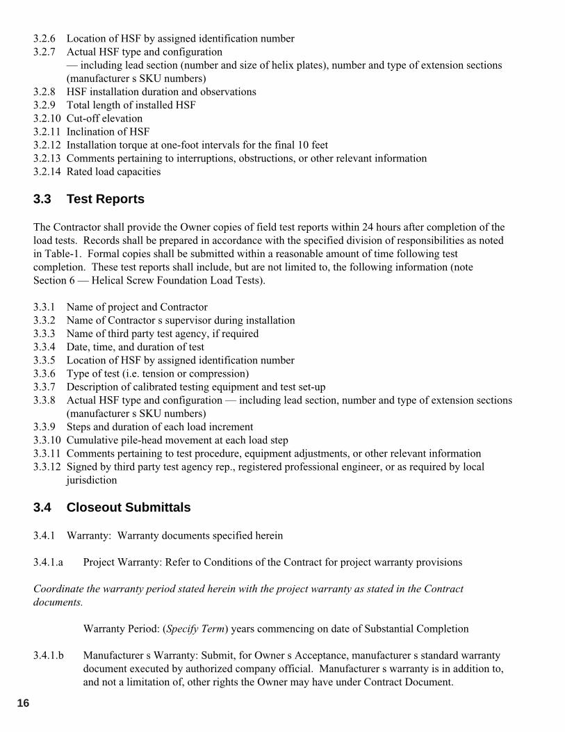
3.2.6 Location of HSF by assigned identification number3.2.7 Actual HSF type and configuration
— including lead section (number and size of helix plates), number and type of extension sections(manufacturer s SKU numbers)
3.2.8 HSF installation duration and observations3.2.9 Total length of installed HSF3.2.10 Cut-off elevation3.2.11 Inclination of HSF3.2.12 Installation torque at one-foot intervals for the final 10 feet3.2.13 Comments pertaining to interruptions, obstructions, or other relevant information3.2.14 Rated load capacities
3.3 Test Reports
The Contractor shall provide the Owner copies of field test reports within 24 hours after completion of theload tests. Records shall be prepared in accordance with the specified division of responsibilities as notedin Table-1. Formal copies shall be submitted within a reasonable amount of time following testcompletion. These test reports shall include, but are not limited to, the following information (noteSection 6 — Helical Screw Foundation Load Tests).
3.3.1 Name of project and Contractor3.3.2 Name of Contractor s supervisor during installation3.3.3 Name of third party test agency, if required3.3.4 Date, time, and duration of test3.3.5 Location of HSF by assigned identification number3.3.6 Type of test (i.e. tension or compression)3.3.7 Description of calibrated testing equipment and test set-up3.3.8 Actual HSF type and configuration — including lead section, number and type of extension sections
(manufacturer s SKU numbers)3.3.9 Steps and duration of each load increment3.3.10 Cumulative pile-head movement at each load step3.3.11 Comments pertaining to test procedure, equipment adjustments, or other relevant information3.3.12 Signed by third party test agency rep., registered professional engineer, or as required by local
jurisdiction
3.4 Closeout Submittals
3.4.1 Warranty: Warranty documents specified herein
3.4.1.a Project Warranty: Refer to Conditions of the Contract for project warranty provisions
Coordinate the warranty period stated herein with the project warranty as stated in the Contractdocuments.
Warranty Period: (Specify Term) years commencing on date of Substantial Completion
3.4.1.b Manufacturer s Warranty: Submit, for Owner s Acceptance, manufacturer s standard warrantydocument executed by authorized company official. Manufacturer s warranty is in addition to,and not a limitation of, other rights the Owner may have under Contract Document.

17
4 PRODUCTS AND MATERIALS
4.1 Central Steel Shaft:
The central steel shaft, consisting of lead sections, helical extensions, and plain extensions, shall be TypeSS or HS or a combination of the two (SS to HS Combo Pile) as manufactured by the A.B. ChanceCompany (Centralia, MO).
4.1.1 SS5 11/2" Material: Shall be hot rolled Round-Cornered-Square (RCS) solid steel bars meetingdimensional and workmanship requirements of ASTM A29. The bar shall be modified mediumcarbon steel grade (similar to AISI 1044) with improved strength due to fine grain size.
4.1.1.a Torsional strength rating = 5,500 ft-lb4.1.1.b Minimum yield strength = 70 ksi
4.1.2 SS150 11/2"; SS175 13/4; SS200 2"; SS225 21/4" Material: Shall be hot rolled Round-Cornered-Square (RCS) solid steel bars meeting the dimensional and workmanship requirements of ASTMA29. The bar shall be High Strength Low Alloy (HSLA), low to medium carbon steel grade withimproved strength due to fine grain size.
4.1.2.a Torsional strength rating: SS150 = 7,000 ft-lb; SS175 = 10,000 ft-lb; SS200 = 15,000 ft-lb;SS225 = 20,000 ft-lb
4.1.2.b Minimum yield strength = 90 ksi
4.1.3 HS 31/2" OD Material: Shall be structural steel tube or pipe, seamless or straight-seam welded, perASTM A53, A252, ASTM A500, or ASTM A618. Wall thickness is 0.300" (schedule 80).
4.1.3.a Torsional strength rating = 11,000 ft-lb4.1.3.b Minimum yield strength = 50 ksi
4.1.4 SS to HS Combo Pile Material: Shall be Type SS and HS material as described above with awelded adapter for the transition from SS to HS.
4.2 Helix Bearing Plate:
Shall be hot rolled carbon steel sheet, strip, or plate formed on matching metal dies to true helical shapeand uniform pitch. Bearing plate material shall conform to the following ASTM specifications.
4.2.1 SS5 Material: Per ASTM A572, or A1018, or A656 with minimum yield strength of 50 ksi. Platethickness is 3/8".
4.2.2 SS150 and SS175 Material: Per ASTM A656 or A1018 with minimum yield strength of 80 ksi.Plate thickness is 3/8".
4.2.3 SS200 and SS225 Material: Per ASTM A656 or A1018 with minimum yield strength of 80 ksi.Plate thickness is Ω".
4.2.4 HS Material: Per ASTM A36, or A572, or A1018, or A656 depending on helix diameter, per theminimum yield strength requirements cited above. Plate thickness is 3/8".

18
4.3 Bolts:
The size and type of bolts used to connect the central steel shaft sections together shall conform to thefollowing ASTM specifications.
4.3.1 SS5 and SS150 11/2" Material: __" diameter bolt per ASTM A320 Grade L7.4.3.2 SS175 13/4" Material: 7/8" diameter bolt per ASTM A193 Grade B7.4.3.3 SS200 2" Material: 11/8" diameter bolt per ASTM A193 Grade B7.4.3.4 SS225 21/4" Material: 11/4" diameter bolt per ASTM A193 Grade B7.4.3.5 HS 31/2" OD Material: __" diameter bolts (3 per coupling) per SAE J429 Grade 5.
4.4 Couplings:
Shall be formed as integral part of the plain and helical extension material. For Type SS material, thecouplings shall be hot upset forged sockets. For Type HS material, the couplings shall be hot forgeexpanded sockets.
4.5 Plates, Shapes, or Pier Caps:
Structural steel plates and shapes for HSF top attachments shall conform to ASTM A36 or ASTM A572Grade 50.
4.6 Corrosion Protection (Optional)
The corrosion protection requirements, if any, are identified in Section 1.8.10. The Specifier may elect todelete this section entirely if no corrosion protection materials are required such as for compressionhelical screw foundations in non-aggressive ground.
4.6.1 Epoxy Coating: If used, the thickness of coating applied electrostatically to the central steel shaftshall be 7-12 mils. Epoxy coating shall be in accordance with ASTM A775. Bend testrequirements are not required. Coupling bolts and nuts are not required to be epoxy coated.
Galvanization: If used, all A.B. Chance Type SS material shall be hot-dipped galvanized in accordancewith ASTM A153 after fabrication. All A.B. Chance Type HS material shall be hot-dipped galvanized inaccordance with ASTM A123 after fabrication.
5 EXECUTION
5.1 Site Conditions
5.1.1 Prior to commencing helical screw foundation installation, the Contractor shall inspect the work ofall other trades and verify that all said work is completed to the point where HSFs may commencewithout restriction.
5.1.2 The Contractor shall verify that all HSFs may be installed in accordance with all pertinent codesand regulations regarding such items as underground obstructions, right-of-way limitations,utilities, etc.
19
5.1.3 In the event of a discrepancy, the Contractor shall notify the Owner. The Contractor shall notproceed with HSF installation in areas of discrepancies until said discrepancies have been resolved.All costs associated with unresolved discrepancies shall be the responsibility of the Owner.
5.2 Installation Equipment
5.2.1 Shall be rotary type, hydraulic power driven torque motor with clockwise and counter-clockwiserotation capabilities. The torque motor shall be capable of continuous adjustment to revolutionsper minute (RPM s) during installation. Percussion drilling equipment shall not be permitted. Thetorque motor shall have torque capacity 15% greater than the torsional strength rating of the centralsteel shaft to be installed.
Helical screw foundations should be installed with high torque, low RPM torque motors, which allow thehelical screw plates to advance with minimal soil disturbance.
5.2.2 Equipment shall be capable of applying adequate down pressure (crowd) and torquesimultaneously to suit project soil conditions and load requirements. The equipment shall becapable of continuous position adjustment to maintain proper HSF alignment.
5.3 Installation Tooling
5.3.1 Shall consist of a Kelly Bar Adapter (KBA) and Type SS or HS drive tool as manufactured by A.B.Chance Company and used in accordance with the manufacturers written installation instructions.
Installation tooling should be maintained in good working order and safe to operate at all times. Flangebolts and nuts should be regularly inspected for proper tightening torque. Bolts, connecting pins, andretainers should be periodically inspected for wear and/or damage and replaced with identical itemsprovided by the manufacturer. Heed all warning labels. Worn or damaged tooling should be replaced.
5.3.2 A torque indicator shall be used during HSF installation. The torque indicator can be an integralpart of the installation equipment or externally mounted in-line with the installation tooling. Torqueindicators are available from A.B. Chance Company.
5.3.2.a Shall be capable of providing continuous measurement of applied torque throughout theinstallation.
5.3.2.b Shall be capable of torque measurements in increments of at least 500 ft-lb5.3.2.c Shall be calibrated prior to pre-production testing or start of work. Torque indicators which are
an integral part of the installation equipment, shall be calibrated on-site. Torque indicatorswhich are mounted in-line with the installation tooling, shall be calibrated either on-site or at anappropriately equipped test facility. Indicators that measure torque as a function of hydraulicpressure shall be calibrated at normal operating temperatures.
5.3.2.d Shall be re-calibrated, if in the opinion of the Owner and/or Contractor reasonable doubt existsas to the accuracy of the torque measurements.
5.4 Installation Procedures
5.4.1 Central Steel Shaft: (Lead and Extension Sections)

20
5.4.1.a The HSF installation technique shall be such that it is consistent with the geotechnical,logistical, environmental, and load carrying conditions of the project.
5.4.1.b The lead section shall be positioned at the location as shown on the working drawings.Battered HSFs can be positioned perpendicular to the ground to assist in initial advancementinto the soil before the required batter angle shall be established. The HSF sections shall beengaged and advanced into the soil in a smooth, continuous manner at a rate of rotation of 5 to20 RPM s. Extension sections shall be provided to obtain the required minimum overall lengthand installation torque as shown on the working drawings. Connect sections together usingcoupling bolt(s) and nut torqued to 40 ft-lb.
5.4.1.c Sufficient down pressure shall be applied to uniformly advance the HSF sections approximately3 inches per revolution. The rate of rotation and magnitude of down pressure shall be adjustedfor different soil conditions and depths.
5.5 Termination Criteria
5.5.1 The torque as measured during the installation shall not exceed the torsional strength rating of thecentral steel shaft.
5.5.2 The minimum installation torque and minimum overall length criteria as shown on the workingdrawings shall be satisfied prior to terminating the helical screw foundation installation.
5.5.3 If the torsional strength rating of the central steel shaft and/or installation equipment has beenreached prior to achieving the minimum overall length required, the Contractor shall have thefollowing options:
5.5.3.a Terminate the installation at the depth obtained subject to the review and acceptance of theOwner, or:
5.5.3.b Remove the existing HSF and install a new one with fewer and/or smaller diameter helix plates.The new helix configuration shall be subject to review and acceptance of the Owner. If re-installing in the same location, the top-most helix of the new HSF shall be terminated at least(3) three feet beyond the terminating depth of the original HSF.
It is generally not recommended to re-use helical screw foundation shaft material after it has beenpermanently twisted during a previous installation.
5.5.4 If the minimum installation torque as shown on the working drawings is not achieved at theminimum overall length, and there is no maximum length constraint, the Contractor shall have thefollowing options:
5.5.4.a Install the HSF deeper using additional extension sections, or:
5.5.4.b Remove the existing HSF and install a new one with additional and/or larger diameter helixplates. The new helix configuration shall be subject to review and acceptance of the Owner. Ifre-installing in the same location, the top-most helix of the new HSF shall be terminated at least(3) three feet beyond the terminating depth of the original HSF.
5.5.4.c De-rate the load capacity of the HSF and install additional helical screw foundation(s). The de-rated capacity and additional helical screw foundation location shall be subject to the reviewand acceptance of the Owner.

21
5.5.5 If the HSF is refused or deflected by a subsurface obstruction, the installation shall be terminatedand the pile removed. The obstruction shall be removed, if feasible, and the HSF re-installed. Ifthe obstruction can t be removed, the HSF shall be installed at an adjacent location, subject toreview and acceptance of the Owner.
5.5.6 If the torsional strength rating of the central steel shaft and/or installation equipment has beenreached prior to proper positioning of the last plain extension section relative to the final elevation,the Contractor may remove the last plain extension and replace it with a shorter length extension.If it is not feasible to remove the last plain extension, the Contractor may cut said extension shaft tothe correct elevation. The Contractor shall not reverse (back-out) the helical screw foundation tofacilitate extension removal.
5.5.7 The average torque for the last three feet of penetration shall be used as the basis of comparisonwith the minimum installation torque as shown on the working drawings. The average torque shallbe defined as the average of the last three readings recorded at one-foot intervals.
The average torque can be empirically related to the helical screw foundation s ultimate capacity in end-bearing. This well-known attribute of screw anchors can be used as a production control method toindicate the HSFs end-bearing capacity.
6 HELICAL SCREW FOUNDATION LOAD TESTS
6.1 Pre-Production Tests (Optional)
Load tests shall be performed to verify the suitability and capacity of the proposed helical screwfoundation, and the proposed installation procedures prior to installation of production screw foundations.___________ sacrificial test screw foundations shall be constructed immediately prior to the start of workon the production HSFs. The Owner shall determine the number of pre-production tests, their location,acceptable load and movement criteria, and the type(s) of load direction (i.e., tension, compression, orboth). Additional purpose of pre-production tests is to empirically verify the ultimate capacity to theaverage installing torque of the helical tieback anchor for the project site.
Pre-production HSF installation methods, procedures, equipment, and overall length shall be identical tothe production HSFs to the extent practical except where approved otherwise by the Owner.
The Contractor shall submit for review and acceptance the proposed HSF load testing procedure. The pre-production test proposal shall be in general conformance with ASTM D1143 and/or D-3689, and shallprovide the minimum following information:♦ Type and accuracy of load equipment♦ Type and accuracy of load measuring equipment♦ Type and accuracy of pile-head deflection equipment♦ General description of load reaction system, including description of reaction anchors♦ Calibration report for complete load equipment, including hydraulic jack, pump, pressure gauge, hoses,
and fittings.
The following test procedure shall be considered to meet the minimum requirements. It is not intended topreclude local building codes, which may mandate other requirements, such as full 24-hour load tests.

22
If the pre-production test fails to meet the design requirements, the Contractor shall modify the helicaltieback anchor design and/or installation methods and retest the modified anchor, as directed by theOwner. For prescriptive specifications, the Engineer will define the appropriate modifications.
6.2 Load Test Equipment
6.2.1 The load test equipment shall be capable of increasing or decreasing the applied loadincrementally. The incremental control shall allow for small adjustments, which may be necessaryto maintain the applied load for a sustained, hold period.
6.2.2 The reaction system shall be designed so as to have sufficient strength and capacity to distribute thetest loads to the ground. It should also be designed to minimize its movement under load and toprevent applying an eccentric load to the pile head. Test loads are normally higher than the designloads on the structure. The direction of the applied load shall be collinear with the HSF at alltimes.
6.2.3 Dial gauge(s) shall be used to measure HSF movement. The dial gauge shall have an accuracy ofat least +/-0.001-in. and a minimum travel sufficient to measure all HSF movements withoutrequiring resetting the gauge. The dial gauge shall be positioned so its stem is parallel with theaxis of the HSF. The stem may rest on a smooth plate located at the pile head. Said plate shall bepositioned perpendicular to the axis of the HSF. The dial gauge shall be supported by a referenceapparatus to provide an independent fixed reference point. Said reference apparatus shall beindependent of the reaction system and shall not be affected by any movement of the reactionsystem.
6.2.4 The load test equipment shall be re-calibrated, if in the opinion of the Owner and/or Contractorreasonable doubt exists as to the accuracy of the load or deflection measurements.
6.3 Testing Program
6.3.1 The hydraulic jack shall be positioned at the beginning of the test such that the unloading andrepositioning of the jack during the test shall not be required. The jack shall also be positioned co-axial with respect to the pile-head so as to minimize eccentric loading. The hydraulic jack shall becapable of applying a load not less than two times the proposed design load (DL). The pressuregauge shall be graduated in 100 psi increments or less. The stroke of the jack shall not be less thanthe theoretical elastic shortening of the total HSF length at the maximum test load.
6.3.2 An alignment load (AL) shall be applied to the HSF prior to setting the deflection measuringequipment to zero or a reference position. The AL shall be no more than 10% of the design load(i.e., 0.1 DL). After AL is applied, the test set-up shall be inspected carefully to ensure it is safe toproceed.
6.3.3 Axial compression or tension load tests shall be conducted by loading the HSF in step-wise fashionas shown in Table-3 to the extent practical. Pile-head deflection shall be recorded at the beginningof each step and after the end of the hold time. The beginning of the hold time shall be defined asthe moment when the load equipment achieves the required load step.

23
Table-3. Steps for Pre-Production Load Testing
LOAD STEP
AL0.20 DL0.40 DL0.50 DL0.20 DL
AL0.40 DL0.60 DL0.80 DL1.0 DL0.5 DL0.2 DL
AL0.5 DL1.0 DL1.2 DL1.4 DL1.6 DL1.8 DL2.0 DL1.5 DL1.0 DL0.5 DL
AL
HOLD TIME(MINUTES)
2.5 Min.2.5 Min.2.5 Min.2.5 Min.1.0 Min.1.0 Min.1.0 Min.2.5 Min.2.5 Min.2.5 Min.1.0 Min.1.0 Min.1.0 Min.1.0 Min.1.0 Min.2.5 Min.2.5 Min.2.5 Min.2.5 Min.1.0 Min.1.0 Min.1.0 Min.1.0 Min.5.0 Min.
AL = Alignment Load; DL = Design Load
6.3.4 Test loads shall be applied until continuous jacking is required to maintain the load step or until thetest load increment equals 200% of the design load (DL) (i.e., 2.0 DL), whichever occurs first. Theobservation period for this last load increment shall be 10 minutes. Displacement readings shall berecorded at 1, 2, 3, 4, 5 and 10 minutes (load increment maxima only).
6.3.5 The applied test load shall be removed in four approximately equal decrements per the schedule inTable-3. The hold time for these load decrements shall be 1 minute, except for the last decrement,which shall be held for 5 minutes.
This cyclic loading method will permit the analyses of the total, elastic, and net movements, since they canbe separated and studied. For special test piles not to be used later in service, further load cycles may beconducted to provide an estimation of the ultimate capacity.
24
6.4 Acceptance Criteria for HSF Verification Load Tests
Both of the following criteria must be met for approval:
1. The HSF shall sustain the compression and tension design capacities (1.0 DL) with no more than ____in. (mm) total vertical movement of the pile-head as measured relative to the top of the HSF prior tothe start of testing.
2. Failure does not occur at the 2.0 DL maximum compression and tension test loads. The failure loadshall be defined by one of the following definitions — whichever results in the lesser load:• The point at which the movement of the HSF tip exceeds the elastic compression/tension of the pile
shaft by 0.08 B, where B is defined as the diameter of the largest helix. (Note that tension loads arelimited to the minimum ultimate tensile strength of the coupling joint(s) of the central steel shaft. Itis recommended to use the minimum ultimate tensile strengths as published by A.B. ChanceCompany (shown in Table-A of the Appendix).
• The point at which the slope of the load versus deflection (at end of increment) curve exceeds 0.05inches/kip.
The Contractor shall provide the Owner copies of field test reports confirming HSF configuration andconstruction details within 24 hours after completion of the load tests. Formal copies shall be submitted asper Section 3.3. This written documentation will either confirm the load capacity as required on theworking drawings or propose changes based upon the results of the pre-production tests.
When a HSF fails to meet the acceptance criteria, modifications shall be made to the design, theconstruction procedures, or both. These modifications include, but are not limited to, de-rating the HSFload capacity, modifying the installation methods and equipment, increasing the minimum effectiveinstallation torque, changing the helix configuration, or changing the HSF material (i.e., central steelshaft). Modifications that require changes to the structure shall have prior review and acceptance of theOwner. The cause for any modifications of design or construction procedures shall be decided in order todetermine any additional cost implications.
6.5 Production Helical Screw Foundation Testing(This may be the only type of load test conducted, depending on project conditions.)
The Contractor shall perform proof tests on a minimum of ___% of the total production HSFs. The helicalscrew foundations to be tested will be selected by the Owner. At the Contractor s suggestion, but with theOwner s permission, tension tests may be performed in lieu of compression tests up to 1.00 DL for HSFswith sufficient structural tension capacity. The requirements of Table-4 may be regarded as a minimum,however, it is not recommended to test production helical screw foundations to values of up to 2.0 DLunless the HSF s failure load is significantly higher than 2.0 DL. The maximum production HSF test loadshall be determined by the Owner. For example, ASTM D1143 stipulates testing to 2.0 DL.
The test sequence shall be as shown in Table-4 to the extent practical.

25
Table-4. Steps for Production Load Testing
LOAD STEP
AL0.20 DL0.40 DL0.60 DL0.80 DL1.00 DL0.60 DL0.40 DL0.20 DL
AL
HOLD TIME(MINUTES)
0 Min.2.5 Min.2.5 Min.2.5 Min.2.5 Min.
5 Min.1 Min.1 Min.1 Min.5 Min.
AL = Alignment Load; DL = Design Load
The acceptance criteria for production helical screw foundations shall be per Section 6.4 Item 1.
If a production HSF that is tested fails to meet the acceptance criteria, the Contractor shall be directed toproof test another HSF in the vicinity. For failed helical screw foundations and further construction ofother foundations, the Contractor shall modify the design, the construction procedure, or both. Thesemodifications include, but are not limited to, installing replacement HSFs, modifying the installationmethods and equipment, increasing the minimum effective installation torque, changing the helixconfiguration, or changing the HSF material (i.e., central steel shaft). Modifications that require changesto the structure shall have prior review and acceptance of the Owner. Any modifications of design orconstruction procedures shall be at the Contractor s expense.
6.6 Lateral Testing
If required, lateral load tests shall be conducted in accordance with ASTM D3966. If a production HSF isto be lateral load tested, care must be taken not to cause permanent damage — which can reduce its axialload capacity. The acceptance criteria as selected by the Owner, typically expressed as a maximum totalmovement at a specific load, must be realistic in its magnitude so as not to potentially damage thestructure. It is suggested that lateral loads be resisted through some other means, such as soil anchors,battered piles, or enlarged concrete pile caps/grade beams.
7 MEASUREMENT AND PAYMENT
Helical screw foundation work can be paid for in different ways, reflecting the relative risk to be acceptedby the Owner and the Contractor. However, the following items are common and standard.

26
♦ Per Unit Length: HSFs meeting the design capacity shall be paid for per lineal foot below grade.♦ Per Helical Screw Foundation: HSFs meeting the design capacity shall be paid for on a per
foundation basis (no allowance for changes in length relative to that originally bid).♦ Per Helical Anchor Foundation with Add/Deduct: HSFs meeting the design capacity shall be paid for
on a per foundation basis, with a predetermined length, and an add/deduct amount per lineal foot toaccommodate field changes.
♦ Lump Sum: The whole HSF project shall be paid for on a lump sum basis (no allowance for changesdue to additional helical screw foundation length relative to that originally bid).
END OF SPECIFICATION
QUANTITY
1As required
As required
-As required
DESCRIPTION
Mobilization/DemobilizationConduct pre-production testprogram of declared scopeTest Production Helical ScrewFoundationsObstructionsHelical Screw FoundationInstallation
UNIT
Lump sumLump sum
Per foundation
Per hour or Force AccountAs below

27
Torsional Strength Rating (ft-lb)
Ultimate Capacity Per Helix (kip)(Tension/Compression)
Allowable Capacity per Helix w/2.0Safety factor (kip) (Tension/Compression)
Ultimate Tension Capacity for AxiallyLoaded Pile (kip)
RATING TYPE CENTRAL STEEL SHAFT FAMILY
SS511/2"RCS
5,500
*40
20
70
SS15011/2"RCS
7,000
*40
20
70
SS17513/4"RCS
10,000
*50
25
100
SS2002"
RCS
15,000
60
30
150
SS22521/4"RCS
20,000
60
30
200
* For 14" Dia. Helix Plates, Reduce the Ultimate Capacity by 20%
NOTE: Actual installed capacities are dependent on existing soil conditions.
APPENDIXTABLE A
A.B. CHANCE COMPANYMechanical Strength Ratings – Helical Screw Foundations
HS31/2" O.D.
Pipe
11,000
50
25
100
PropertyResistivity
pH
Sulfate
Chloride
Organic Content
Test Designation
below 2,000 ohm-cm
below 5
above 200 ppm
above 100 ppm
1% max
Critical ValuesASTM G 57AASHTO T-28ASTM G 51AASHTO T-289ASTM D 516MASTM D 4327ASTM D 512ASTM D 4327AASHTO T-291AASHTO T-267
APPENDIXTABLE B
Guidance of Ground Aggressiveness ClassificationSoil tests may be performed to measure the aggressiveness of the soil environment, especially if fieldobservations indicate corrosion of existing structures. The most common and simplest tests are forelectrical resistivity, pH, chloride, and sulfates. The designation for these tests and the critical valuesdefining whether an aggressive soil environment exists, are as shown below. Per FHWA-RD-89-198, theground is considered aggressive if any one of these indicators shows critical values.

NOTE: Because Hubbell has a policy of continuous product improvement, we reserve the right to change design and specifications without notice.
Printed in U.S.A. ©Copyright 2003 Hubbell / ChanceRGS 2M 7/03
ISO 9001-1994Cert. No. 001136
A.B. Chance Co.Centralia, MO USA
To locate a Certified Installer in your local area,consult our Distributor Network listed on
http://www.abchance.com
®®®ANDERSON ®
UNITED STATESHUBBELL POWER SYSTEMS, INC.
210 N. Allen
Centralia, Mo 65240
Phone: 573-682-8414
Fax: 573-682-8660
e-mail: [email protected]
CANADAHUBBELL CANADA, INC.
870 Brock Road South
Pickering, Ontario L1W 1Z8
Phone: 905-839-1138
Fax: 905-831-6353
e-mail: [email protected]
EUROPEHUBBELL POWER SYSTEMS
Ronald Close
Woburn Road Industrial Estate
Kempston, Bedford
MK42 7SH, England
Phone: 44-1-234-843632
Fax: 44-1-234-841435
e-mail: [email protected]
MEXICOHUBBELL DE MEXICO, S.A. DE. CV
Av. Coyoacan No. 1051
Col. Del Valle
03100 Mexico, D.F.
Phone: 52-55-9151-9999
Fax: 52-55-9151-9988
e-mail: [email protected]
ASIAHUBBELL S.E. ASIA PTE. LTD.
159 Sin Ming Road
#05-08 Amtech Building
Singapore 575625
Phone: 65-6454-4772
Fax: 65-6454-4775
e-mail: [email protected]
E-mail: [email protected]
Bulletin 01-0303


