MODEL REFERENCE ADAPTIVE CONTROL SYSTEM FOR …
18
SAIIE25 Proceedings, 9 th 11 th July 2013, Stellenbosch, South Africa © 2013 SAIIE 524-1 MODEL REFERENCE ADAPTIVE CONTROL SYSTEM FOR MOISTURE REGULATION IN COTTON GINNING T.Garikayi 1* , L. Nyanga 2 , T. Mushiri 3 , S. Mhlanga 4 , A. Muzinda 5 T. Mutangi 6 1 Department of Industrial and Manufacturing Engineering, Harare Institute of Technology, Zimbabwe [email protected] 2 Stellenbosch University, Department of Industrial Engineering, South Africa [email protected] 3 Department of Mechanical Engineering, University of Zimbabwe [email protected] 4 Department of Industrial Engineering, University of Johannesburg, South Africa [email protected], 5 Department of Mechatronics Engineering, Chinhoyi University of Technology, Zimbabwe [email protected] 6 Department of Industrial and Manufacturing Engineering, National University of Science and Technology, Zimbabwe [email protected] ABSTRACT Moisture content (mc) within the cotton fibre is an important aspect for all stages of the ginning process. However due to the process dynamics, mc is currently being controlled by regulating the water and air temperatures from the Humidifiers. Human intervention and lack of consistence on set-points determination has resulted in inconsistent mc during humidification. This procedure requires a control system which will be able to adjust the process set-points automatically by eliminating the need for human intervention. In this paper a robust Model Reference Adaptive Control (MRAC) system for a Samuel Jackson Humidifier is presented. This system improves upon the existing system by creating a closed loop controller with parameters that can be updated to change the response from reference model. The control parameters are then updated based on this error thus the parameters converge to ideal values that cause the plant response to match the response of the reference model. Keywords: Model Reference Adaptive Control (MRAC), Moisture Content (mc) * Corresponding Author brought to you by CORE View metadata, citation and similar papers at core.ac.uk provided by University of Johannesburg Institutional Repository
Transcript of MODEL REFERENCE ADAPTIVE CONTROL SYSTEM FOR …
SAIIE25 Proceedings, 9th -‐11th July 2013, Stellenbosch, South Africa © 2013 SAIIE
524-1
MODEL REFERENCE ADAPTIVE CONTROL SYSTEM FOR MOISTURE REGULATION IN COTTON GINNING
T.Garikayi1* , L. Nyanga2, T. Mushiri3, S. Mhlanga4, A. Muzinda5 T. Mutangi6
1 Department of Industrial and Manufacturing Engineering, Harare Institute of Technology, Zimbabwe
2Stellenbosch University, Department of Industrial Engineering, South Africa [email protected]
3 Department of Mechanical Engineering, University of Zimbabwe
4Department of Industrial Engineering, University of Johannesburg, South Africa [email protected],
5Department of Mechatronics Engineering, Chinhoyi University of Technology,
Zimbabwe [email protected]
6Department of Industrial and Manufacturing Engineering, National University of Science and Technology, Zimbabwe
ABSTRACT
Moisture content (mc) within the cotton fibre is an important aspect for all stages of the ginning process. However due to the process dynamics, mc is currently being controlled by regulating the water and air temperatures from the Humidifiers. Human intervention and lack of consistence on set-points determination has resulted in inconsistent mc during humidification. This procedure requires a control system which will be able to adjust the process set-points automatically by eliminating the need for human intervention. In this paper a robust Model Reference Adaptive Control (MRAC) system for a Samuel Jackson Humidifier is presented. This system improves upon the existing system by creating a closed loop controller with parameters that can be updated to change the response from reference model. The control parameters are then updated based on this error thus the parameters converge to ideal values that cause the plant response to match the response of the reference model. Keywords: Model Reference Adaptive Control (MRAC), Moisture Content (mc)
*Corresponding Author
brought to you by COREView metadata, citation and similar papers at core.ac.uk
provided by University of Johannesburg Institutional Repository
SAIIE25 Proceedings, 9th -‐11th July 2013, Stellenbosch, South Africa © 2013 SAIIE
524-2
1. INTRODUCTION
The need to control dynamic processes and make informed decisions using imprecise and partial data has resulted in the emerging of intelligent systems. Hence there is need to design an on-line parameter estimator so as to minimize human intervention during the process operation. Over the years, control of processes and systems in the industry was customarily done by experts through the conventional Proportional, Integral and Derivative (PID) control techniques. Recently the logic controllers such as the Programmable Automation Controller (PAC) and the Programmable Logic Controllers (PLC) have managed to replace most process operations handling large quantities of inputs and outputs. This is as a result of their simplicity, low cost design and robust performance in a wide range of operating condition [1]. According to Khan [2] although the PID controllers have gained widespread usage across technological industries, it must also be pointed out that the unnecessary mathematical rigorosity, preciseness and accuracy involved with the design and tuning of these controllers have been a major drawback. This has made it difficult if not impossible for designers, engineers and technology experts to design intelligent complex systems, nonlinear systems, higher order and time-delayed linear systems that can satisfactorily behave as expected while operating in the human-machine interface [3].
The research is a case study based research on moisture control techniques and the challenges which the organization is currently facing on quality control of the lint product during gentle ginning. Due to the process dynamics it is very difficult to directly measure the moisture content within the lint during the ginning process, however it is possible to predict the moisture content using the water temperature, moist air temperature, fuel control valve and water control valve positions.
International Cotton Advisory Committee [4] stated that a ginner have two objectives: (1) to produce lint of satisfactory quality for the grower's classing and market system, and (2) to gin the cotton with minimum reduction in fiber spinning quality so that the cotton will meet the demands of its ultimate users, the spinner and the consumer. However the quality properties (staple length, moisture content and fibre colour) of the lint and the rate of production in ginning highly depends on the moisture content hence failure to regulate moisture content will also result in the creation of fires due to static charges.
According to Koo [5] and Shyu et al [6] apart from the MIT rule there are some other design techniques in Model reference Adaptive Control System, such as Lyapunov theory and the theory of augmented error, in this paper the emphasis is given to MIT rule only for developing the MRAC scheme. Simulation is done in MATLAB and results are shown for the first order system.
The estimation of process parameters by process operators during humidification has resulted in poor fibre quality and inconsistent moisture content. Thus intelligent systems simulate human thinking and behaviour. There is however not yet an Artificial Intelligence (AI) system that can truly replace human thinking, reasoning and creativity although each AI system mimics some specific aspect of human thinking.
The general idea behind Model Reference Adaptive Control (MRAC) is to create a closed loop controller with parameters that can be updated to change the response

SAIIE25 Proceedings, 9th -‐11th July 2013, Stellenbosch, South Africa © 2013 SAIIE
524-3
of the system. The output of the system is compared to a desired response from a reference model. The control parameters are updated based on this error. The goal is for the parameters to converge to ideal values that cause the plant response to match the response of the reference model.
In this paper, an improved MRAC system for moisture generation is presented. The rest of the paper is organized as follows; Section 2 introduces the problem domain of the moisture control system and the benefits for proper moisture regulation in gentle ginning system. Section 3 presents an overview of the MRAC system development procedure using the MIT-Rule, the review of already existing MRAC system and how the available system can easily be integrated with the designed MRAC. In section 4, the results of the developed system are described along with the explanation of its outstanding features and robustness relative to existing PID systems, followed by some concluding remarks in section 5.
2. MOISTURE CONTROL IN GINNING
The moisture content of seed cotton is critical for efficient gin operation and so as to preserve intrinsic fibre quality. The ideal moisture range for cotton ginning is 6.5-8% for upland cotton and 5-6% for Egyptian/Pima cotton. According to Gerald [7] when gin machinery is used in the recommended sequence, 75-85% of the foreign matter is usually removed from cotton. Cleaning is more efficient in dry cotton, but drying fiber lower than 4% moisture can cause increased static electricity problems and fiber breakage because fiber strength is inversely related to moisture content. On the other hand, cotton that is too moist doesn't separate into locks but remain in wads, which can choke the ginning machinery. A mathematical model that predict seed-cotton moisture content using the air (moist and hot)temperature, fuel valve , water pump speed to account for heat transfer from the conveying air, heat added to the room and the seed-cotton, and the heat added to the water in the seed cotton is presented in this paper. Byler [8] advocates that fibre quality is improved when lint moisture content at the gin stand is in the range of 6% to 7% wet basis compared to the lower levels. However the moisture content is variable to such an extent that the moisture at the lower levels such as the mixing floor and the distributor (screw) or overflow bins is even far much less than what Byler [8] has stated since the experiments done for the mixing floor and the distributor have revealed mc as low as 4%. Therefore moisture levels are greatly affected by outside gin temperatures thus the ginning period has a great impact on moisture levels. The overall quality of fibre produced by gins would be improved if the moisture control system will be able to add moisture to the lint as well as subtract it when necessary. The optimum moisture for fibre seed separation is 6.5% to 8% wet basis Griffith [9] or even higher ,Moore[10]; however due to the reduced cleaning efficiency the optimum moisture for ginning is considered to be in the range from 6-7 % wet basis . Moisture can be stored safely at a moisture levels below 8% [11].
The upper limit for safe storage of seed cotton is 12% moisture content [12]. If moisture is greater than 12% it should be ginned immediately to avoid fibre quality degradation. Lint represent about 35% of the seed cotton mass and cottonseed represents about 58% with the remainder being trash. Thus 635.03 Kg of seed cotton is required to produce a 217.72 Kg bale lint and about 371.95 Kg of cottonseed. Therefore at the maximum safe storage level of 12% seed cotton moisture, the lint is about 9% moisture and cotton seed about 13% moisture [11]. Cotton is dried at gins in order to increase cleaning efficiency of the machines and to improve the

SAIIE25 Proceedings, 9th -‐11th July 2013, Stellenbosch, South Africa © 2013 SAIIE
524-4
appearance of the cotton fibre. The Cotton Ginner’s Handbook [13] recommends maximum fibre moisture at ginning of 7%. Thus an analysis of the ginning process will mean that there is need for moisture restoration at the lint slide, since they will be a loss of moisture during bale pressing. Ginners often add moisture at the lint slide so as to reduce bale-pressing packaging forces and to recover some of the weight lost during ginning at the gin stands. Experiments and process observations done have revealed that most humidifiers as shown in Figure 1 add approximately 2Kg-6Kg of water per bale if properly regulated.
Hot Air Humidification or Hot Air Moisture restoration in a cotton gin can have a huge impact on profitability. Some of the salient features are given below:
i. Instant humidification by easing out wax surface of the fibre and recuperation after humidification by cooling effect for retained moisture.
ii. Preserves fiber length, improves strength and uniformity and reduces short fiber content.
iii. Eliminates moisture condensation which is a general problem with all other moisturisation techniques.
iv. It increases the lint slide capacity and allows more cotton to enter the press box at each stroke of the tramper and hence higher density bale is obtained.
v. Improves the capacity of the bale press whereas dry cotton requires higher compression forces and more time to charge and compact it into the press box.
vi. Achieves better sliding of lint in the lint slide.
Figure 1: The Humidifier Unit © Samuel Jackson Humidair Units
Hot humid air is inducted in the lint on a lint slide with a set of louvers at temperature around 45 to 500C Degree Celsius. The hot air eases out the surface tension of the fibre and humidity is transferred to inner stem while air passes out.

SAIIE25 Proceedings, 9th -‐11th July 2013, Stellenbosch, South Africa © 2013 SAIIE
524-5
The cooling down recuperates the fibre surface and maximum moisture contents are retained by fibre for a longer period.
3. THE MRAC SYSTEM DEVELOPMENT
According to Orkin et al [14] the computer revolution has also been a primary force in the expansion of quality activity into service businesses and functions. Adaptive control involves modifying the control law used by the controller to cope with the fact that the parameters of the system being controlled change drastically due to change in environmental conditions or change in system itself [15]. This technique is based on the fundamental characteristic of adaptation of living organism. In other terms the adaptive control process is one that continuously and automatically measures the dynamic behavior of plant process, compares it with the desired output and uses the difference to vary adjustable system parameters or to generate an actuating signal in such a way so that optimal performance can be maintained regardless of system changes.
Wong [16] defined adaptive control as the control method used by a controller which must adapt to a controlled system with parameters which vary, or are initially uncertain. When applied to moisture restoration a control law is needed that adapts itself to such changing conditions such as temperature, flow rate and pressures. It does not need a priori information about the bounds on these uncertain or time-varying parameters, adaptive control is concerned with control law changes as the parameters changes. Hence the adaptive control is the attempt to “redesign” the controller while online, by looking at its performance and changing its dynamic in an automatic way. Adaptive control is that feedback law that looks at the process and the performance of the controller and reshapes the controller closed loop behaviour autonomously.
The foundation of adaptive control is parameter estimation. Common methods of estimation include recursive least squares and gradient descent. Both of these methods provide update laws which are used to modify estimates in real time (i.e., as the system operates). Lyapunov stability is used to derive these update laws and show convergence criterion (typically persistent excitation). Projection mathematics and normalization are commonly used to improve the robustness of estimation algorithms [17].
Usually these recursive least squares and gradient descent methods adapt the controllers to both the process statics and dynamics. In special cases the adaptation can be limited to the static behaviour alone, leading to adaptive control based on characteristic curves for the steady-states or to extreme value control, optimizing the steady state. Hence, there are several ways to apply adaptive control algorithms. Adaptive Control is made by combining online parameter estimator based on current measurements and control actions and control law that recalculates the controller based on those parameters. There are two main modalities of adaptive control; direct and indirect cases.
Indirect adaptive control, which is one of two distinct approaches for the control of dynamical plants with unknown parameters, as it is commonly used, consists of two stages. In the first stage, the parameters of the plant are estimated dynamically on-line using input-output information Kreisselmeier [18] and Middleton [19]. At every instant of time, assuming that the estimates represent the true values of the plant parameters, the control parameters are computed to achieve desired overall system
SAIIE25 Proceedings, 9th -‐11th July 2013, Stellenbosch, South Africa © 2013 SAIIE
524-6
characteristic. In contrast with this, in direct adaptive control the control parameters are adjusted continuously based on the error between the output of the plant and the output of the reference model. The latter results in the overall system being described by a set of non-linear differential equations, this in turn makes the formulation of the stability problems of such systems relatively straightforward. Duarte [20] concluded that while the two methods have continued to flourish for over two decades, very little is known about the precise relation between them.
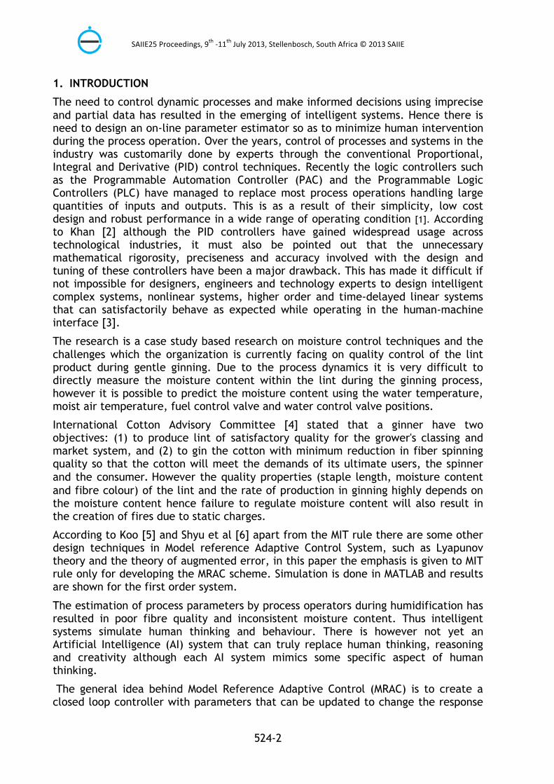
The general idea behind Model Reference Adaptive Control (MRAC) is to create a closed loop controller with parameters that can be updated to change the response of the system. The output of the system yplant is compared to a desired response from a reference model ymodel. The control parameters are updated based on this error. The goal is for the parameters to converge to ideal values that cause the plant response to match the response of the reference model. The design seeks among other things to control the position of modulating fuel valve and the water regulating valve as the temperature and changes. The research seeks to make quick motions with little or no vibration for the precise positions proportional to the error changes (error = yplant - ymodel). Using MRAC one can choose a reference model that respond quickly to a step input with a short settling time, and then build such a desired controller as shown in Figure 2.
Figure 2: Model Reference Adaptive Control Schematic
Nowadays the adaptive control schemes are making their place where the conventional control system is not able to cope-up with the situation such as [15]:
§ Loads, inertias and other forces acting on system change drastically.
§ Possibility of unpredictable and sudden faults.
§ Possibility of frequent or unanticipated disturbances.
4. DEVELOPING THE MODEL REFERENCE ADAPTIVE CONTROL (MRAC) -SYSTEM BASED ON THE MIT RULE
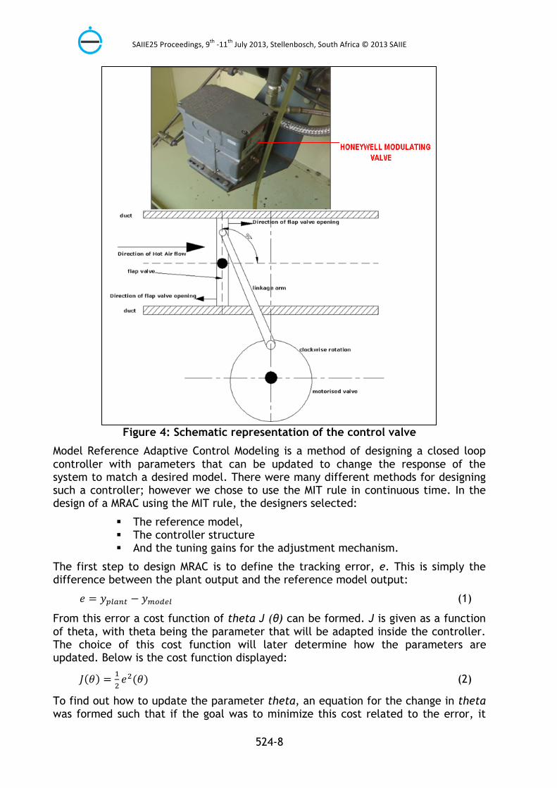
Moisture regulation is achieved by automatically regulating the position of valves .The moisture generation unit consists of a Honeywell Modulating hot-air valve with a 4-20mA signal card. The main purpose of this hot-air flap valve is to increase the temperature of the humid air so as to minimize condensation of the humid air before
SAIIE25 Proceedings, 9th -‐11th July 2013, Stellenbosch, South Africa © 2013 SAIIE
524-7
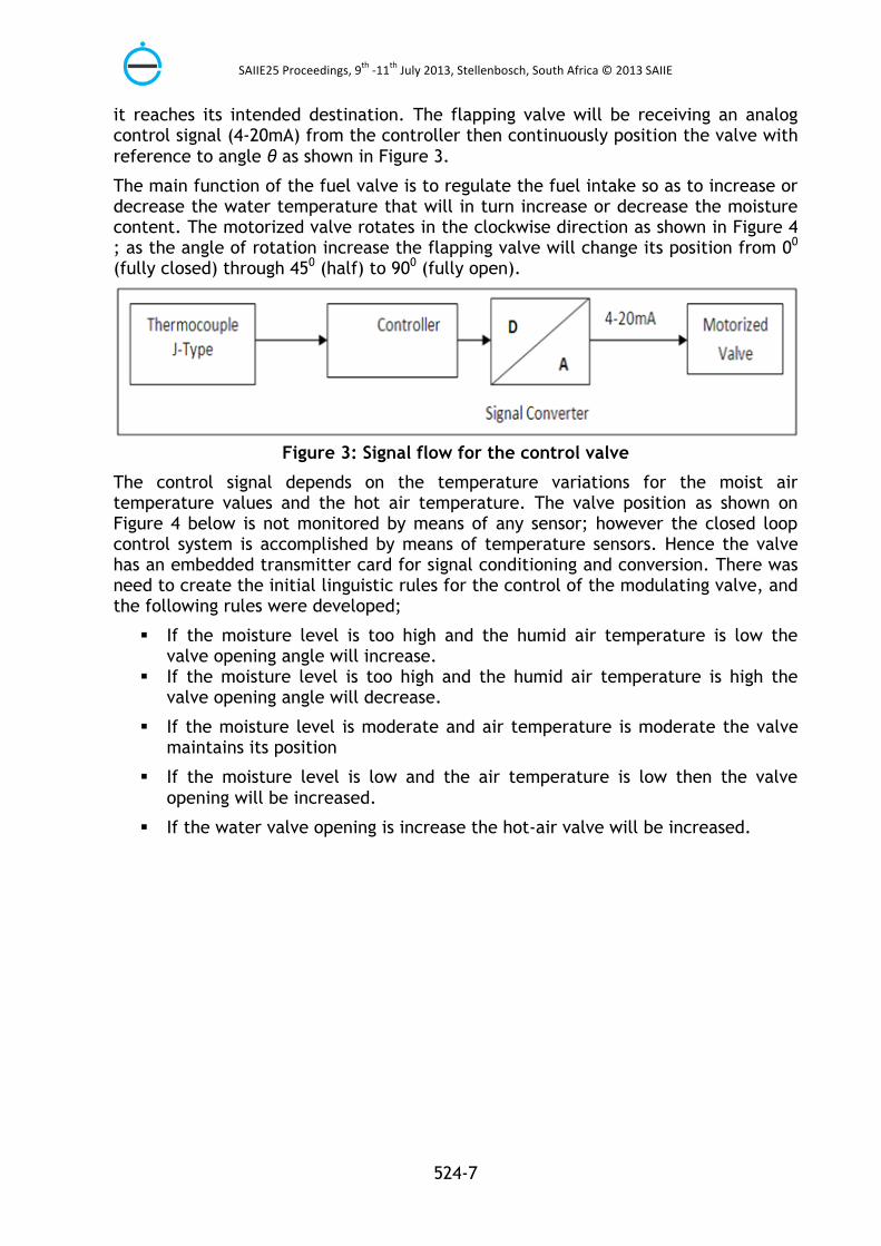
it reaches its intended destination. The flapping valve will be receiving an analog control signal (4-20mA) from the controller then continuously position the valve with reference to angle θ as shown in Figure 3.
The main function of the fuel valve is to regulate the fuel intake so as to increase or decrease the water temperature that will in turn increase or decrease the moisture content. The motorized valve rotates in the clockwise direction as shown in Figure 4 ; as the angle of rotation increase the flapping valve will change its position from 00 (fully closed) through 450 (half) to 900 (fully open).
Figure 3: Signal flow for the control valve
The control signal depends on the temperature variations for the moist air temperature values and the hot air temperature. The valve position as shown on Figure 4 below is not monitored by means of any sensor; however the closed loop control system is accomplished by means of temperature sensors. Hence the valve has an embedded transmitter card for signal conditioning and conversion. There was need to create the initial linguistic rules for the control of the modulating valve, and the following rules were developed;
§ If the moisture level is too high and the humid air temperature is low the valve opening angle will increase.
§ If the moisture level is too high and the humid air temperature is high the valve opening angle will decrease.
§ If the moisture level is moderate and air temperature is moderate the valve maintains its position
§ If the moisture level is low and the air temperature is low then the valve opening will be increased.
§ If the water valve opening is increase the hot-air valve will be increased.
SAIIE25 Proceedings, 9th -‐11th July 2013, Stellenbosch, South Africa © 2013 SAIIE
524-8
Figure 4: Schematic representation of the control valve
Model Reference Adaptive Control Modeling is a method of designing a closed loop controller with parameters that can be updated to change the response of the system to match a desired model. There were many different methods for designing such a controller; however we chose to use the MIT rule in continuous time. In the design of a MRAC using the MIT rule, the designers selected:
§ The reference model, § The controller structure § And the tuning gains for the adjustment mechanism.
The first step to design MRAC is to define the tracking error, e. This is simply the difference between the plant output and the reference model output:
𝑒𝑒 = 𝑦𝑦 − 𝑦𝑦 (1)
From this error a cost function of theta J (θ) can be formed. J is given as a function of theta, with theta being the parameter that will be adapted inside the controller. The choice of this cost function will later determine how the parameters are updated. Below is the cost function displayed:
𝐽𝐽 𝜃𝜃 = 𝑒𝑒 (𝜃𝜃) (2)
To find out how to update the parameter theta, an equation for the change in theta was formed such that if the goal was to minimize this cost related to the error, it
SAIIE25 Proceedings, 9th -‐11th July 2013, Stellenbosch, South Africa © 2013 SAIIE
524-9
was sensible to move in the direction of the negative gradient of J. This change in J is assumed to be proportional to the change in theta. Thus, the derivative of theta is equal to the negative change in J. The result for the cost function chosen previously above is:
= −𝛾𝛾 (3)
Thus
−𝛾𝛾 = −𝛾𝛾𝛾𝛾 (4)
Where – 𝛾𝛾𝛾𝛾 is the sensitivity derivative of the system
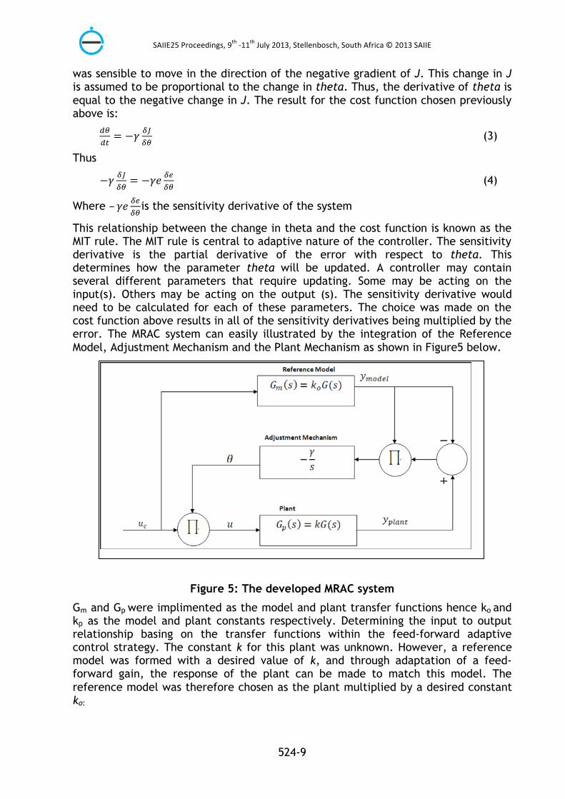
This relationship between the change in theta and the cost function is known as the MIT rule. The MIT rule is central to adaptive nature of the controller. The sensitivity derivative is the partial derivative of the error with respect to theta. This determines how the parameter theta will be updated. A controller may contain several different parameters that require updating. Some may be acting on the input(s). Others may be acting on the output (s). The sensitivity derivative would need to be calculated for each of these parameters. The choice was made on the cost function above results in all of the sensitivity derivatives being multiplied by the error. The MRAC system can easily illustrated by the integration of the Reference Model, Adjustment Mechanism and the Plant Mechanism as shown in Figure5 below.
Figure 5: The developed MRAC system
Gm and Gp were implimented as the model and plant transfer functions hence ko and kp as the model and plant constants respectively. Determining the input to output relationship basing on the transfer functions within the feed-forward adaptive control strategy. The constant k for this plant was unknown. However, a reference model was formed with a desired value of k, and through adaptation of a feed-forward gain, the response of the plant can be made to match this model. The reference model was therefore chosen as the plant multiplied by a desired constant ko:
SAIIE25 Proceedings, 9th -‐11th July 2013, Stellenbosch, South Africa © 2013 SAIIE
524-10
( )( )= 𝑘𝑘𝑘𝑘(𝑠𝑠) (5)
However using the same cost function in equation (2)
We have
= −𝛾𝛾𝛾𝛾 (6)
The error in equation (1) is then restated in terms of the transfer functions multiplied by their inputs.
𝑒𝑒 = 𝑦𝑦 − 𝑦𝑦 (7)
𝑒𝑒 = 𝑘𝑘𝑘𝑘𝑘𝑘 − 𝐺𝐺 𝑈𝑈 (8)
𝑒𝑒 = 𝑘𝑘𝑘𝑘𝑘𝑘𝑈𝑈 − 𝑘𝑘 𝐺𝐺𝑈𝑈 (9)
As can be seen, this expression for the error contains the parameter theta (Ө) which is to be updated. To determine the update rule, the sensitivity derivative was calculated and restated in terms of the model output:
= 𝑘𝑘𝑘𝑘𝑈𝑈 (10)
But
𝑘𝑘𝑘𝑘𝑈𝑈 = 𝑦𝑦 (11)
Therefore
= 𝑦𝑦 (12)
Finally, the MIT rule was applied to give an expression for updating theta. The constants k and ko were combined into gamma.
= −𝛾𝛾 ′ 𝑦𝑦 𝑒𝑒 = −𝛾𝛾𝑦𝑦 𝑒𝑒 (13)
To tune this system, the values of ko and gamma were varied. The MIT rule by itself does not guarantee convergence or stability. An MRAC designed using the MIT rule was very sensitive to the amplitudes of the signals. As a general rule, the value of gamma was kept small. Tuning of gamma was crucial to the adaptation rate and stability of the controller. It was then assumed that the controller has both an adaptive feedforward Ө1 and an adaptive feedback Ө2 gain as illustrated in Figure 7. To derive expressions for the sensitivity derivatives associated with these parameters, the error function was restated to include Ө1 and Ө2. The equation for the error was first rewritten as the transfer function of the plant and model multiplied by their respective inputs. The input Uc is not a function of either of the adaptive parameters, and therefore can be ignored for now. However, the input U was rewritten using the feedforward and feedback gains. This was used to derive an equation for Yplant.
The control valve will receive an analogue signal between 4-20mA from the main Omron PLC controller. The control valve is such that it will open from Δθ0 for temperature increase ΔT for time Δt seconds so as to achieve the control objective as shown on Figure 8. The valve will open up to 900 maximum, it is however not advisable to operate the system towards large values of θ0. As Δθ0 increases with respect to the fuel intake the fuel consumption will also increase hence the cost of
SAIIE25 Proceedings, 9th -‐11th July 2013, Stellenbosch, South Africa © 2013 SAIIE
524-11
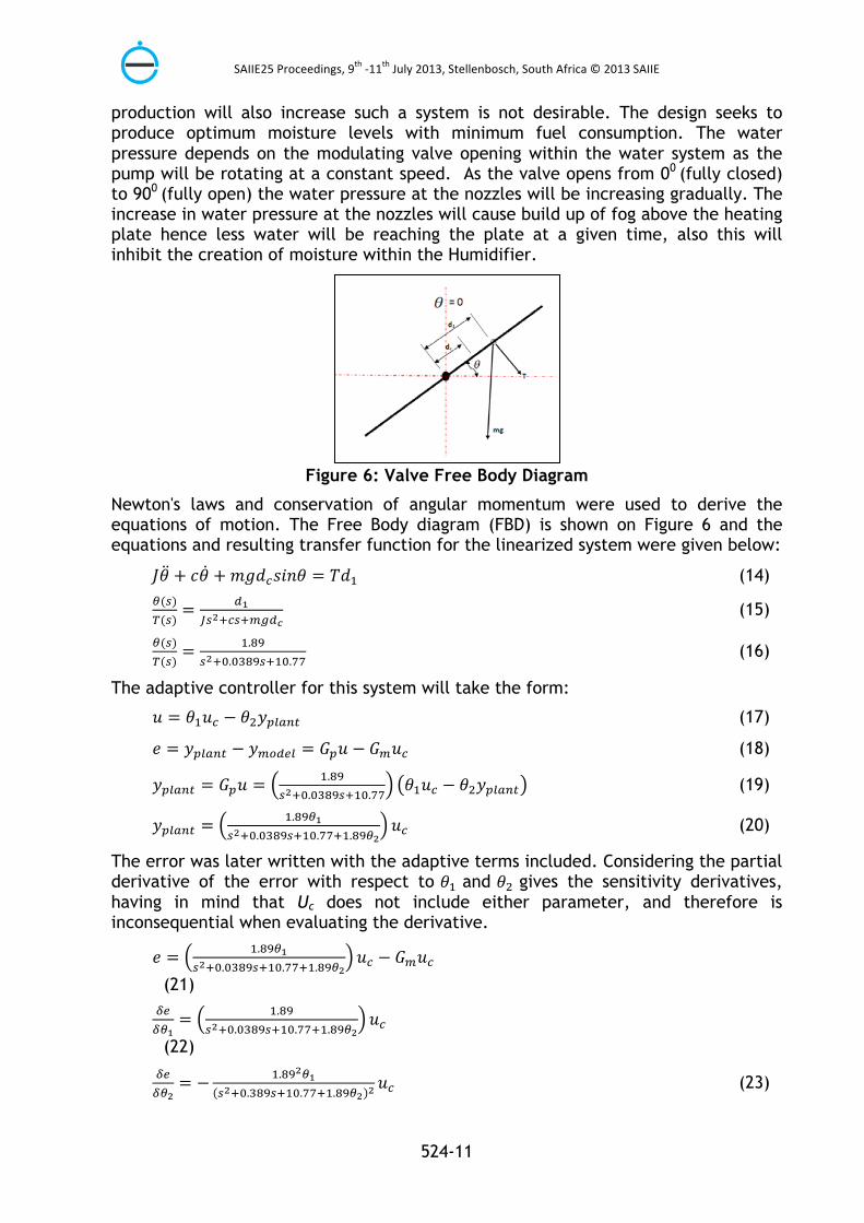
production will also increase such a system is not desirable. The design seeks to produce optimum moisture levels with minimum fuel consumption. The water pressure depends on the modulating valve opening within the water system as the pump will be rotating at a constant speed. As the valve opens from 00 (fully closed) to 900 (fully open) the water pressure at the nozzles will be increasing gradually. The increase in water pressure at the nozzles will cause build up of fog above the heating plate hence less water will be reaching the plate at a given time, also this will inhibit the creation of moisture within the Humidifier.
Figure 6: Valve Free Body Diagram
Newton's laws and conservation of angular momentum were used to derive the equations of motion. The Free Body diagram (FBD) is shown on Figure 6 and the equations and resulting transfer function for the linearized system were given below:
𝐽𝐽𝜃𝜃 + 𝑐𝑐𝜃𝜃 +𝑚𝑚𝑚𝑚𝑑𝑑 𝑠𝑠𝑠𝑠𝑠𝑠𝑠𝑠 = 𝑇𝑇𝑑𝑑 (14) ( )( )= (15)
( )( )= .
. . (16)
The adaptive controller for this system will take the form:
𝑢𝑢 = 𝜃𝜃 𝑢𝑢 − 𝜃𝜃 𝑦𝑦 (17)
𝑒𝑒 = 𝑦𝑦 − 𝑦𝑦 = 𝐺𝐺 𝑢𝑢 − 𝐺𝐺 𝑢𝑢 (18)
𝑦𝑦 = 𝐺𝐺 𝑢𝑢 = .. .
𝜃𝜃 𝑢𝑢 − 𝜃𝜃 𝑦𝑦 (19)
𝑦𝑦 = .. . .
𝑢𝑢 (20)
The error was later written with the adaptive terms included. Considering the partial derivative of the error with respect to 𝜃𝜃 and 𝜃𝜃 gives the sensitivity derivatives, having in mind that Uc does not include either parameter, and therefore is inconsequential when evaluating the derivative.
𝑒𝑒 = .. . .
𝑢𝑢 − 𝐺𝐺 𝑢𝑢
(21)
= .. . .
𝑢𝑢
(22)
= − .. . .
𝑢𝑢 (23)

SAIIE25 Proceedings, 9th -‐11th July 2013, Stellenbosch, South Africa © 2013 SAIIE
524-12
= − .. . .
𝑦𝑦 (24)
The sensitivity derivatives obtained contain the parameters from the plant. The premise of design with MRAC assumes that the plant characteristics were not absolutely known. This seemingly places the design process at a dead end. However, the goal was to make the plant approach the model. If the model is close to the actual plant, the model characteristics can be substituted for the plant characteristics, giving the following sensitivity derivatives:
Substituting
𝑠𝑠 + 0.0389𝑠𝑠 + 10.77+ 1.89𝜃𝜃 with 𝑠𝑠 𝑎𝑎 𝑠𝑠 + 𝑎𝑎
With
𝑠𝑠 𝑎𝑎 𝑠𝑠 + 𝑎𝑎
Taking the derivative of the feedforward loop of the MRAC we have;
= 𝑢𝑢 (25)
= − 𝑦𝑦 (26)
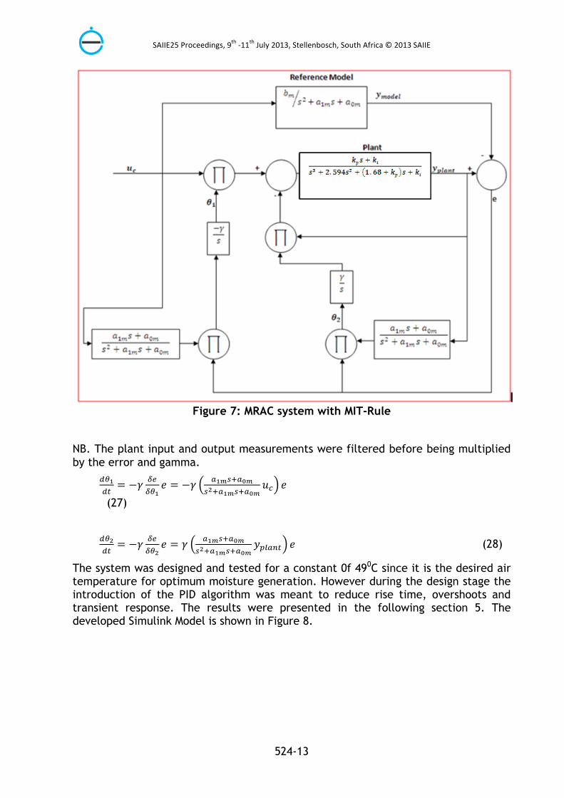
Then, applying the MIT rule, the update rules for each Theta was written. The block diagram for the system with the derived controller is shown on Figure 7.
SAIIE25 Proceedings, 9th -‐11th July 2013, Stellenbosch, South Africa © 2013 SAIIE
524-13
Figure 7: MRAC system with MIT-Rule
NB. The plant input and output measurements were filtered before being multiplied by the error and gamma.
= −𝛾𝛾 𝑒𝑒 = −𝛾𝛾 𝑢𝑢 𝑒𝑒
(27)
= −𝛾𝛾 𝑒𝑒 = 𝛾𝛾 𝑦𝑦 𝑒𝑒 (28)
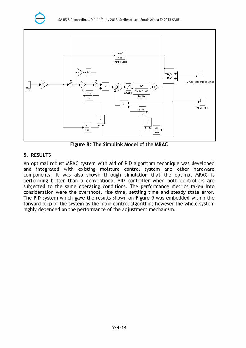
The system was designed and tested for a constant 0f 490C since it is the desired air temperature for optimum moisture generation. However during the design stage the introduction of the PID algorithm was meant to reduce rise time, overshoots and transient response. The results were presented in the following section 5. The developed Simulink Model is shown in Figure 8.
SAIIE25 Proceedings, 9th -‐11th July 2013, Stellenbosch, South Africa © 2013 SAIIE
524-14
Figure 8: The Simulink Model of the MRAC
5. RESULTS
An optimal robust MRAC system with aid of PID algorithm technique was developed and integrated with existing moisture control system and other hardware components. It was also shown through simulation that the optimal MRAC is performing better than a conventional PID controller when both controllers are subjected to the same operating conditions. The performance metrics taken into consideration were the overshoot, rise time, settling time and steady state error. The PID system which gave the results shown on Figure 9 was embedded within the forward loop of the system as the main control algorithm; however the whole system highly depended on the performance of the adjustment mechanism.
SAIIE25 Proceedings, 9th -‐11th July 2013, Stellenbosch, South Africa © 2013 SAIIE
524-15
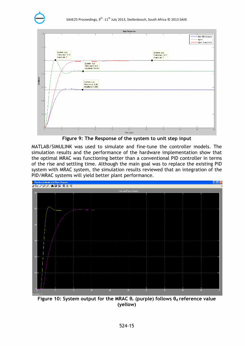
Figure 9: The Response of the system to unit step input
MATLAB/SIMULINK was used to simulate and fine-tune the controller models. The simulation results and the performance of the hardware implementation show that the optimal MRAC was functioning better than a conventional PID controller in terms of the rise and settling time. Although the main goal was to replace the existing PID system with MRAC system, the simulation results reviewed that an integration of the PID/MRAC systems will yield better plant performance.
Figure 10: System output for the MRAC θr (purple) follows θd reference value
(yellow)
SAIIE25 Proceedings, 9th -‐11th July 2013, Stellenbosch, South Africa © 2013 SAIIE
524-16
The system showed a negative error difference as shown on Figure 10 which is mainly as result of the heating effect of the stainless steel flat plate heat exchanger. As the system temperature will be increasing the MRAC system will be comparing the Reference Model and the Actual plant output, therefore there is need to introduce a delay within the actual hardware components.
The system had a set-point of 490C hence the desired value was reached with an overshoot when using a PID system alone, however when integrated with a MRAC system the system achieved the desired set-point without any significant overshoots. However the settling time was 15 seconds as compared to the 5 seconds on the PID system. The deviation in settling time could not be further eliminated.
6. CONCLUSION
In this paper a MRAC system has been presented in this paper. The objective of achieving optimum moisture content within the lint and at the ginning point with minimum to no human intervention while updating system inputs on real time mode by direct comparison of the Reference Model output with the actual plant output was solved with aid of MRAC system in this paper. Furthermore, the MRAC approach improves many failures of the fixed-gains controller, such as: some large overshoots and undershoots lead to burnout of the devices at the transient, need to retune gains for different operation regions and pressed for robustness.
The experimental results have demonstrated that the proposed approach effectively eliminates the need for the process operators to measure the moisture after every five lint bales that is a sample after every twenty minutes which will in turn take between five to fifteen minutes (an average of to adjust the moisture value the implementation of the proposed design will mean that the system will be adjusted in real time with aid of moisture sensors at the gin stands and lint slide and the fuel and water modulating valves at the Humidifier Unit.
7. REFERENCES
[1] Khan, S., Abdulazeez, S.F, Adetunji, L.W., Alam, A.H.M.Z., Salami, M.J.E., Hameed, S.A., Abdalla, S.A. and Islam, M.R. .2008. Design and Implementation of an Optimal Fuzzy Logic Controller Using Genetic Algorithm, Journal of Computer Science, 4(10), pp 799-806.
[2] Kumar, M. and Garg, D.P. 2004. Intelligent learning of fuzzy logic controllers via neural network and genetic algorithm. Proceedings of the Japan-USA Symposium on Flexible Automation, July 19-21, Colorado, pp: 1-8.
[3] Tang, K.S., Man, K.F., Chen, G and Kwong, S. 2001. An optimal fuzzy PID controller, IEEE Transactions on Industrial Electronics, 48(4), pp 757-765
[4] Anthony, W., Van Doorn, D., Edwards, E., Pearson, T., Malloum, I, Kechagia, U., Ozdemir, I. amd Nyoni, D. 2001. Impact of ginning on fiber quality: the best ginning practices, International Cotton Advisory Committee Recorder, 27 p, Accessed from: http://www.icac.org/tis/misc/expert_panel_ginning_methods_sept01.pdf, Accessed on: 21 February 2013
[5] Koo, T.J. 2001. Stable Model Reference Adaptive Fuzzy Control of a Class of Nonlinear Systems, IEEE Transactions on Fuzzy Systems, 9(4), pp 624-636.
SAIIE25 Proceedings, 9th -‐11th July 2013, Stellenbosch, South Africa © 2013 SAIIE
524-17
[6] Kuo-Kai, S., Ming-JiYang, Y.M. and Yi-Fei, L. 2008. Model Reference Adaptive Control Design for a Shunt Active-Power-Filter System, IEEE Transactions On Industrial Electronics, 55(1), pp 97-106.
[7] Estur, G. and Gergely, N. 2010 .The Economics of Roller Ginning Technology and Implications for African Cotton Sector. Africa Region Working Paper Series No. 129 (a), World Bank, Accessed from: http://www.worldbank.org/afr/wps/wp129a.pdf, Accessed on 21 February 2013
[8] Byler R. K. 2008. .Seed cotton moisture restoration in a commercial gin, Applied Engineering in Agriculture, 24(5), pp 587-59.
[9] Griffin, A. C. and Columbus, E. P., 1982, Dust in Cotton Gins: An Overview, in J.G. Montalvo (ed), Cotton Dust, ACS Symposium Series, Vol 189. pp 27-36
[10] Moore, V. P. and A. C. Griffin. 1964. The relationship of moisture to cotton quality preservation at gins. USDA-ARS ARS 42-105, Washington, DC: USDA. 11p.
[11] Anthony, W. S., R. K. Byler, L. Deavenport, and D. M. Scamardo. 1995. Experiences with gin process control in the Midsouth and West, Applied engineering in agriculture, 11(3), pp 409-414.
[12] Lalor, W. F., Willcutt, M. H. and Curley, R. G. 1994. Seed cotton storage and handling. In Cotton Ginners Handbook. USDA Handbook No. 503, pp. 16-25.
[13] Anthony, W.S. and Mayfield, W.D. 1995. Cotton Ginners Handbook, DIANE Publishing
[14] Orkin, F. I. and Olivier, D. 1999. Computer Applications To Quality Systems, Juran's quality handbook, McGraw-Hill.
[15] Pankaj, K., Kumar, J.S. and Nema, R.K. 2011. Comparative Analysis of MIT Rule and Lyapunov Rule in Model Reference Adaptive Control Scheme, Innovative Systems Design and Engineering, 2(4) , pp 154-162
[16] Wong L.K .1998. Lyapunov-Function-Based Design of Fuzzy Logic Controllers and Its Application on Combining Controllers, IEEE Transactions on Industrial Electronics, 45(3), pp 502 -‐ 509
[17] Chen Y.R, Wu, J and Cheung, N.C. 2001. Lyapunov Stability Theory-Based Model Reference Adaptive Control for Permanent Magnet Linear Motor Drives, Proceedings of First International Conference on Power Electronics Systems and Applications, 9-11 Nov. 2004, Hong Kong, China, pp 260 - 266.
[18] Kreisselmeier, G. 1985. An approach to stable indirect adaptive control, Automatica, 21(4), pp 425-431.
[19] Middleton, R. 1985. Indirect continuous time adaptive control, Automatica, 23(6), pp 793-795.
[20] Duarte, M.A. 1996. Indirect model reference adaptive control with dynamic adjustment of parameters, International journal of adaptive control and signal processing, Vol 10, pp 603-621

SAIIE25 Proceedings, 9th -‐11th July 2013, Stellenbosch, South Africa © 2013 SAIIE
524-18


![ISSN 1751-8660 Stator current model reference adaptive ... · 10], model reference adaptive systems (MRAS) [4, 11–14] and artificial intelligence (AI)-based methods [3, 15]. Recent](https://static.fdocuments.us/doc/165x107/5f8f07aece1bf147d45f13fe/issn-1751-8660-stator-current-model-reference-adaptive-10-model-reference.jpg)