
Model PM-1236 Lathe - Precision Matthews€¦ · My lathe doesn’t run at all (1) This manual...
45
PM-236 v4 -207.indd Model PM-1236 Lathe High precision gap-bed machine 36 in. between centers, 2 in. swing over bed, 7-/2 in. over gap 2 HP (500W) motor, 220 Vac single phase Speed range from 65 to 80 rpm Power cross-feed, traveling motor controls D-4 camlock spindle mount, -/2 inch spindle bore Weight, including stand, 200 lb PM-1236 with optional coolant system, live center and QC toolpost 70 Parkway View Drive Pittsburgh, PA 5205 Copyright © 206 Quality Machine Tools, LLC
Transcript of Model PM-1236 Lathe - Precision Matthews€¦ · My lathe doesn’t run at all (1) This manual...

�PM-�236 v4 �-20�7.indd
Model PM-1236 Lathe
High precision gap-bed machine36 in. between centers, �2 in. swing over bed, �7-�/2 in. over gap
2 HP (�500W) motor, 220 Vac single phaseSpeed range from 65 to �8�0 rpm
Power cross-feed, traveling motor controlsD�-4 camlock spindle mount, �-�/2 inch spindle bore
Weight, including stand, �200 lb
PM-1236 with optional coolant system, live center and QC toolpost
70� Parkway View Drive Pittsburgh, PA �5205 Copyright © 20�6 Quality Machine Tools, LLC

2PM-�236 v4 �-20�7.indd
PM-1236
FAQ
POWER light off, bottom arrow?
240 Vac power connected?
Circuit breaker in the electrical box tripped?
E-STOP button in, top arrow? Rotate it, should pop out.
My lathe doesn’t run at all (1)
This manual contains essential safety advice on the proper setup, operation, maintenance, and service of the PM-�236 lathe. Failure to read, understand and follow the manual may result in property damage or serious personal injury.
There are many alternative ways to install and use a lathe. As the owner of the lathe you are solely re-sponsible for its proper installation and safe use. Consider the material contained in this manual to be advisory only. Precision Matthews, LLC cannot be held liable for injury or property damage during instal-lation or use, or from negligence, improper training, machine modifications or misuse.
This manual describes PM-�236 machines as shipped from April 20�6. There may be detail dif-ferences between your specific machine and the information given here (with little or no impact on functionality). If you have questions about any aspect of the manual or your machine, please call 412-787-2876 (east coast time), or email us at [email protected]. Your feedback is welcomed!
Belt cover in place? This closes the inter-lock switch, bottom arrow. FOOTBRAKE working, not stuck down? If working properly, the footbrake should close the microswitch, top arrow, opening it when released.
CHUCK GUARD swung back? Close the guard.
The motor didn’t run when power was connected
My lathe doesn’t run at all (2)
By design it should NOT run if the Motor Control switch was UP or DOWN when power is connected.
Electrical schematic, Section 5: Move the Motor Control switch to neutral, mid travel, to energise the power-switch-ing contactor KA, thus restoring normal conditions.

3PM-�236 v4 �-20�7.indd
Section 1 INSTALLATION
THESE ARE THE MAIN POINTS TO WATCH OUT FOR!But read the following pages for more information
Handling the lathe is at least a two-man job.Lifting gear – sling, hoist or forklift – must be rated for at least � ton.Working location of the mill must allow space for removal of the belt cover at left, also ac-cess to the coolant system (back of right hand cabinet) and the electrical box at the back of the headstock.Power requirement is 240V, 60Hz, 1φ, 20A circuit protection (spindle motor 14A full load).Extension cord not recommended; if no alternative, use �2 AWG not longer than 20 ft.Before connecting power be sure that:
The machine is on a firm footing, adequately secured to its stand.Chuck camlocks tight, no wrench left in chuck.Carriage and cross slide approx. mid-travel, power feed disengaged (Figure �-�0).The headstock gear selectors are set for the lowest spindle speed.
•••
•••
�.2.3.4.
�. Prepare the working location for the stand. If you in-tend to use an engine hoist, there must be room for the hoist, Figure �-5. If not, a forklift and slings may be a better option. If only an engine hoist is avail-able, with limited space either side, the machine can be fully assembled on a pair of 4-wheel dollies, then rolled to its final position. The assembly can then be raised by screw jack or other means to free the dol-lies.
2. Position the LH and RH stand cabinets 34 inches apart in the lathe’s final location. Mark the floor to allow the cabinets to be repositioned in the same locations for final assembly, when the front panel and footbrake components have been installed.
3. Remove the coolant tank and pump assembly, if supplied, from the RH cabinet, Figure �-�.
4. Highly recommended! Install leveling mounts rated for 250 lb each at the
corners of the two stand cabinets. (Alternatively, plan on using metal shims under the cabinets to level the lathe after securing it to the cabinets.)
5. Install front panel brackets on the two cabinets, Fig-
ure �-2, using four M6 screws and washers.
SETTING UP THE LATHEThe PM-�236 is shipped in three packing cases, one for the machine/chip tray/front panel/back splash, one each for the left and right hand stand cabinets. The follow-ing procedure makes use of an engine hoist, minimum weight rating � ton.
Figure �-� Coolant pump and tank
Figure �-2 In-facing side of cabinets

4PM-�236 v4 �-20�7.indd
Figure �-4 Hoisting the lathe
Figure �-3Footbrakecomponents
6. With the RH cabinet in its approximate final location, insert the footbrake pivot shaft, then locate the other end of the shaft in the LH cabinet while easing the cabinet into its final location.
7. Install the front panel on the brackets using four M6 screws, washers and nuts.
8. Position the chip tray on the stands, aligning the 6 holes for mounting bolts with the corresponding threaded holes on top of the cabinets..
9. Unpack the footbrake components stowed in the LH cabinet, then assemble the drawbar (2 pieces), crank and extension spring as Figure �-3 (see Foot-brake adjustment, next page, also Stand and Cool-ant Components diagram, Section 5).
�0. Remove the packing case from the pallet, then un-bolt the machine from the pallet.
��. Run two �000 lb slings under the lathe bed and up to the hoist hook. The slings must be inboard of the leadscrew, feed shaft and motor control rod to avoid damage to those components.
�2. Slowly lift the lathe, controlling any tendency for it to swing as it clears the pallet.
�3. Roll the lathe into position, Figure �-5, then hover it an inch or so over the chip tray. This will allow you to mark the perimeters of the lathe bed pedestals for the purpose of caulking.
�4. Apply a thick bead of silicone caulk just inside the marked perimeters on the tray.
�5. Lower the lathe onto the chip tray, making sure that its six mounting holes are properly aligned. Excess caulk squeezed out by the pedestals will form a coolant-proof seal.
�6. Install the six supplied M�2 x 40 hex head bolts with washers. Fully tighten the bolts. Re-check the caulk-ing on both pedestals.
�7. Install the backsplash using four M6 screws and washers.
Figure �-5 Lowering onto stand
CLEANUPMetal surfaces may be protected by thick grease and/or paper. Carefully remove these using a plastic paint scraper, disposable rags and a light-oil such as WD-40.
5PM-�236 v4 �-20�7.indd
LEVELINGMake sure the lathe is in its permanent location. The leveling procedure ensures that the lathe bed is in the same state as it was when the lathe was checked for ac-curacy in manufacture — level from end to end along the bed, and from front to back. In other words, no warping.
Make sure all leveling mounts and/or shims are proper-ly weight bearing, firmly in contact with the floor. Check and adjust level from end to end using a “precision machinist’s level”, if available. If not, use the most reli-able level on hand. Check and adjust level front-to-back across the bed using a matched pair of spacer blocks to clear the Vee tenons on the bed ways. The blocks need to be at least �/4 inch thick, ground or otherwise accu-rately dimensioned. Alternatively, check for level on the ground surface of the cross slide as the carriage is tra-versed from end to end. See also "Checking Alignment" later in this section.
FOOTBRAKE ADJUSTMENTThis is a two-man procedure, see Figure �-3:
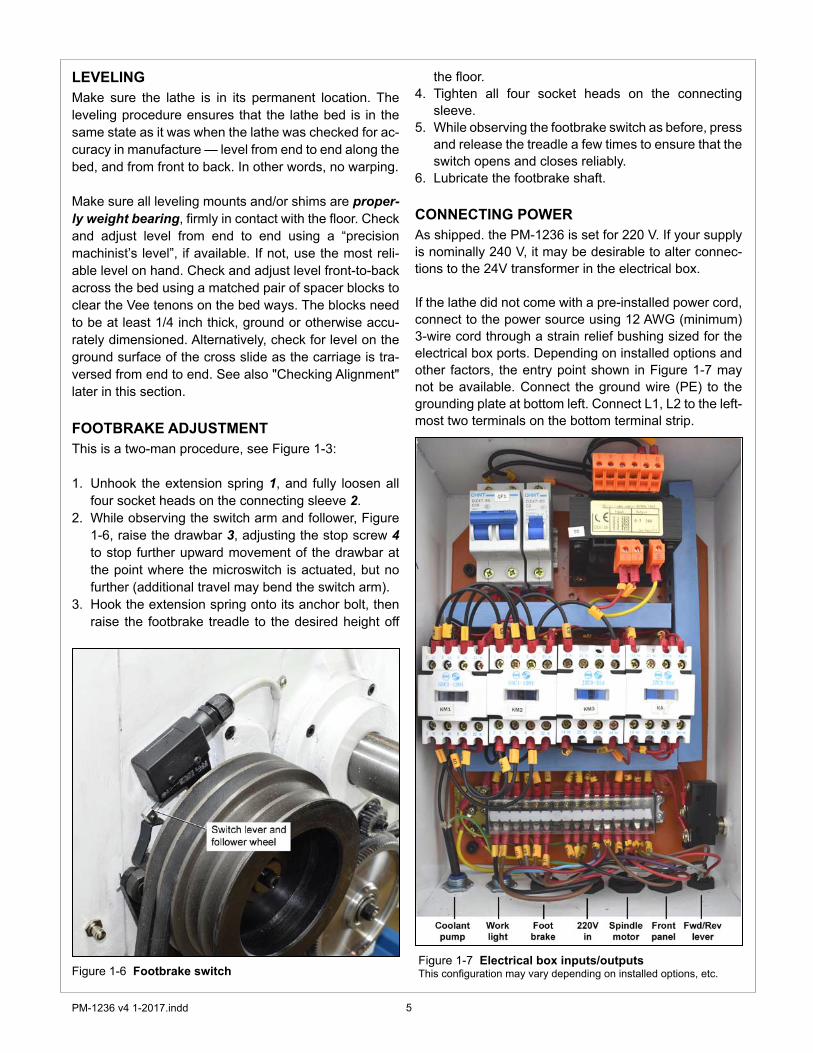
Unhook the extension spring 1, and fully loosen all four socket heads on the connecting sleeve 2.While observing the switch arm and follower, Figure �-6, raise the drawbar 3, adjusting the stop screw 4 to stop further upward movement of the drawbar at the point where the microswitch is actuated, but no further (additional travel may bend the switch arm).Hook the extension spring onto its anchor bolt, then raise the footbrake treadle to the desired height off
�.
2.
3.
Figure �-6 Footbrake switch
the floor.Tighten all four socket heads on the connecting sleeve.While observing the footbrake switch as before, press and release the treadle a few times to ensure that the switch opens and closes reliably.Lubricate the footbrake shaft.
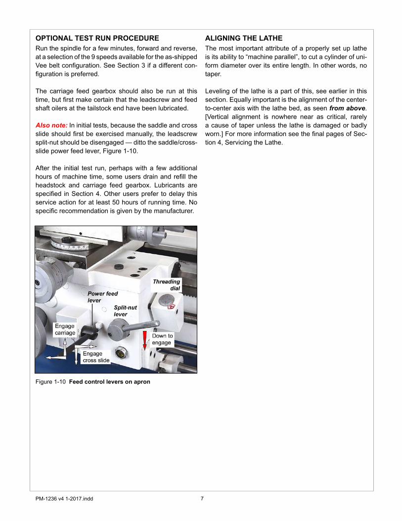
CONNECTING POWERAs shipped. the PM-�236 is set for 220 V. If your supply is nominally 240 V, it may be desirable to alter connec-tions to the 24V transformer in the electrical box.
If the lathe did not come with a pre-installed power cord, connect to the power source using �2 AWG (minimum) 3-wire cord through a strain relief bushing sized for the electrical box ports. Depending on installed options and other factors, the entry point shown in Figure �-7 may not be available. Connect the ground wire (PE) to the grounding plate at bottom left. Connect L�, L2 to the left-most two terminals on the bottom terminal strip.
4.
5.
6.
Figure �-7 Electrical box inputs/outputsThis configuration may vary depending on installed options, etc.

6PM-�236 v4 �-20�7.indd
INITIAL CHECKS
Read Section 3 if unsure about any item in the fol-lowing
Check oil level (sight glasses) in the headstock, the carriage feed gearbox, and the apron. See Section 4, Figures 4-� to 4-6. Remove the belt cover left of the headstock. Make sure the belt is properly tensioned and set for the desired speed range. If not, re-position the belt, Figure �-8, also see Figure 3-4.
�.
2.
Figure �-9 Forward/Reverse motor controlMid-travel OFF, Down FORWARD, Up REVERSE
Figure �-8 Drive belt adjustment
Set the spindle speed gear levers to B-�. Depend-ing on the drive belt configuration, High or Low speed, this will give a speed of 65 or �00 rpm. Do not change speed when the motor is running.
6.
Replace the belt cover. If a chuck is installed check tightness of the three Camlocks on the spindle nose, Figure 3-8.Lower the chuck guard, if installed, Figure �-9.
3.4.
5.
Check that there are no clamps or locks on moving parts.Check that the footbrake treadle is released (UP).Set the carriage and cross slide to approximate mid-travel.Make certain that the power feed levers are disen-gaged, Figure �-�0.Make certain that the motor control switch is set to OFF, mid-travel, Figure �-9.
7.
8.9.
�0.
��.
Figure �-9 Chuck guard
Connect 220 Vac power. The power lamp (far left of the orange color E-Stop button) should light, unless circuit breaker QF� in the electrical box has tripped.Be sure the E-Stop button has not been pushed in (it should pop out when twisted clockwise). Shift the motor control lever DOWN. The spindle should turn forward, counter clockwise, viewed at the chuck (nose) end. Check the emergency function by pressing the E-Stop button. The motor should stop. If this doesn’t happen, the E-stop function is defective, and needs attention.Reset (twist) the E-Stop button to restore power.Check that the chip guard switch stops the motor when the guard is swung up.Check that the belt cover interlock stops the motor when the belt cover is removed.Check that the footbrake stops the motor.Return the motor control lever to OFF, mid-travel. The motor should stop.Shift the motor control lever UP. The spindle should reverse, clockwise rotation, viewed at the chuck (nose) end.
�2.
�3.
�4.
�5.
�6.�7.
�8.
�9.20.
2�.
7PM-�236 v4 �-20�7.indd
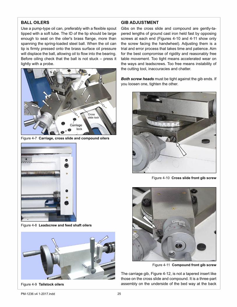
OPTIONAL TEST RUN PROCEDURERun the spindle for a few minutes, forward and reverse, at a selection of the 9 speeds available for the as-shipped Vee belt configuration. See Section 3 if a different con-figuration is preferred.
The carriage feed gearbox should also be run at this time, but first make certain that the leadscrew and feed shaft oilers at the tailstock end have been lubricated.
Also note: In initial tests, because the saddle and cross slide should first be exercised manually, the leadscrew split-nut should be disengaged — ditto the saddle/cross-slide power feed lever, Figure �-�0.
After the initial test run, perhaps with a few additional hours of machine time, some users drain and refill the headstock and carriage feed gearbox. Lubricants are specified in Section 4. Other users prefer to delay this service action for at least 50 hours of running time. No specific recommendation is given by the manufacturer.
Figure �-�0 Feed control levers on apron
ALIGNING THE LATHEThe most important attribute of a properly set up lathe is its ability to “machine parallel”, to cut a cylinder of uni-form diameter over its entire length. In other words, no taper.
Leveling of the lathe is a part of this, see earlier in this section. Equally important is the alignment of the center-to-center axis with the lathe bed, as seen from above. [Vertical alignment is nowhere near as critical, rarely a cause of taper unless the lathe is damaged or badly worn.] For more information see the final pages of Sec-tion 4, Servicing the Lathe.

8PM-�236 v4 �-20�7.indd
Section 2 FEATURES & SPECIFICATIONSMODEL PM-1236 Lathe
General informationThe PM-�236 is a robust gap-bed lathe designed for day-in, day-out use in the model shop. Distance between centers is 36 in., swing over the bed �2 in. With an all-up weight of �000 lb, plus a wide range of speeds from 65 to �8�0 rpm, the PM-�236 can handle far more than the typical small machine. The spindle nose is D�-4 Cam-lock. A quick-change carriage feed gearbox provdes a full range of leadscrew ratios for U.S. and metric screw cutting, together with an independent power feed for both saddle and cross slide. The power feed shaft is driven through a friction clutch that allows the saddle to be stopped precisely at any point along the bed.
The spindle has a �-�/2 in. clearance bore and MT5 internal taper. It runs in tapered-roller bearings, and is driven by a 9-speed gearbox, coupled by Vee-belts to a 2 HP (�500 W) 220 Vac single-phase motor. Two-step pulleys provide a choice of high and low speed drives, giving a total of �8 spindle speeds — 9 high range plus 9 low range. A treadle-operated disc brake stops the spindle in milliseconds, even at the highest speeds. A circulating coolant system (optional) may be installed in the right hand stand cabinet.
Supplied accessories6 in. 3-jaw self centering chuck with two sets of jaws, in-facing and out-facing 8 in. 4-jaw independent chuck with reversible jawsSteady restFollower restMicrometer saddle stop
•
••••
PM-1236 Floor plan: dimensions approximate (not to scale)

9PM-�236 v4 �-20�7.indd
PM-1236 SPECIFICATIONSIncluding stand: Width 61-1/2 in., Height 55 in.Depth 19 in. at chip tray, add 8 in. for cross slide
Weight (approximate numbers) Lathe 960 lb net, 1020 lb shipping Cabinet, left hand, incl. foot brake linkage Cabinet, right hand, incl. coolant pump (option)
Power requirement 220 - 240Vac, 60 Hz, 1Ø, 12A full load Motor TEFC type, cap start, 1.5 kW (2 HP), 1725 rpm
Work envelope Distance between centers 36 in. Gap insert length 9 in. Swing over gap 17-1/2 in. diameter Swing over bed 12 in. diameter Swing over cross slide 7 in. diameter Saddle travel 30-1/2 in. Cross-slide travel 6-1/8 in. Compound (top slide) travel 3-1/4 in.
Drive system (High/Low belt drive with 9-speed gearbox) Low range, rpm 65, 180, 200, 235, 330, 550, 700, 910, 1200 High range, rpm 100, 280, 300, 360, 500, 840, 1095, 1400, 1810
Carriage drive, thread cutting Leadscrew 8 tpi Inch threads Choice of 36, from 4 to 60 tpi Metric threads Choice of 32, from 0.4 to 7 mm pitch
Carriage drive, turning operations Choice of feed rates from 0.002 to 0.048 in./spindle rev Cross slide drive Choice of feed rates from 0.001 to 0.009 in./spindle rev
Spindle Chuck/faceplate attachment D1-4 Camlock Internal taper MT5 Spindle bore Clearance for 1-1/2 in. diameter Spindle length 15-5/8" overall
Tailstock Internal taper MT3 Quill travel 4 in.
Work holdingCapacity, 1/8 in. to 6 in. diameterWeight: 22 lbCapacity: 3/8 in. to 8 in. diameterWeight: 34 lb
Faceplate 10 in. diameter Center rest (steady rest) capacity 3/16 to 1-1/2 in. diameter Follower rest capacity 1/4 to 3/4 in. diameter
100 lb shipping weight, each
Dimensions, approximate overall
3-jaw chuck, 6 in., self-centering (scroll)
4-jaw chuck, 8 in., independent

�0PM-�236 v4 �-20�7.indd
Everyday precautions• This machine is intended for use by experienced users familiar with metal-
working hazards.
• Untrained or unsupervised operators risk serious injury.
• Wear ANSI-approved full-face or eye protection at all times when using the machine (everyday eyeglasses are not reliable protection against flying par-ticles).
• Wear proper apparel and non-slip footwear – be sure to prevent hair, clothing or jewelry from becoming entangled in moving parts. Gloves – including tight-fitting disposables – can be hazardous!
• Be sure the work area is properly lit.
• Never leave chuck keys, wrenches or other loose tools on the machine. • Be sure the workpiece, toolholder(s) and machine ways are secure before
commencing operations.
• Use moderation: light cuts, low spindle speeds and slow table motion give better, safer results than “hogging”.
• Don’t try to stop a moving spindle by hand – allow it to stop on its own. • Disconnect 220 Vac power from the mill before maintenance operations such
as oiling or adjustments.
• Maintain the machine with care – check lubrication and adjustments daily before use.
• Clean the machine routinely – remove chips by brush or vacuum, not com-pressed air (which can force debris into the ways).
No list of precautions can cover everything. You cannot be too careful!

��PM-�236 v4 �-20�7.indd
Section 3 USING THE LATHE
MOTOR CONTROLSBefore doing anything, check the installation in-structions and power-up procedure in Section 1
Before connecting power to the lathe, be sure the motor control lever is set to OFF, Figure 3-2. Connect the lathe to a 220 Vac outlet — the POWER lamp should light — then operate the motor control lever to run the spindle in both directions.
Check that the following interlocks function correctly:E-Stop button.Chuck guard, if installed.
••
Figure 3-2 Set the motor control to OFF (mid travel)
SPINDLE DRIVE TRAINTwo-step double-groove pulleys connect the motor to the gearbox, Figure 3-3. The low speed configuration gives spindle speeds from 65 to �200, high speed from �00 to �8�0 rpm. Because many users find that the low range is suitable for most of their work, there is typically no need to swap belts — unless a particular job calls for a 50% speed increase. If the drive needs to be recon-figured, Loosen the three hex head bolts securing the
Figure 3-3 Twin Vee belts drive the headstock gearbox
WHAT IS NOT IN THIS SECTION ...The PM-�236 is a conventional engine lathe that re-quires little explanation except for details specific to this particular model — speed selection, thread cutting, and the carriage/cross slide power feed system. Because the user is assumed to be familiar with general purpose metal lathes, this section contains very little tutorial.
CONTROL PANELIn addition to three gear shift levers (speed and feed direction) the main control panel also includes a “jog” control. This a momentary type push-button indepen-dent of the motor control switch right of the apron. When operated, ithe jog button runs the spindle in the forward direction, stopping when released.
Figure 3-� Main control panel
Belt cover (to the left of the headstock).Footbrake
••

�2PM-�236 v4 �-20�7.indd
SPINDLE SPEEDSThe PM-�236 has a nine-speed headstock gearbox with two shift levers C-B-A and 1-2-3, Figure 3-�. Before changing speed, STOP THE MOTOR, Figure 3-2, then move each shift lever to the desired setting. This may need a little patience because it is not always possible to go directly from one mesh to another. Move the spindle back and forth by hand while trying to ease the lever into its detent (meshed) position. Don’t use the JOG button in this process — this may cause gear damage.
motor, Figure 3-4. Raise the motor to de-tension the Vee belts. Move the belts to select the other speed range, then lower the motor to re-tension. Make certain the mo-tor is properly aligned, then re-tighten the bolts.
Figure 3-4 Motor bolts
SPINDLE SPEED (RPM)1 2 3
HIGHRANGE
A 360 �8�0 �095B �00 500 300C 280 �400 840
LOWRANGE
A 235 �200 700B 65 330 200C �80 9�0 550
CHUCKS & FACEPLATEThe spindle nose on the PM-�236 accepts D�-4 Cam-lock chucks, faceplates and other work holding devices.
A D�-4 chuck or faceplate is held by three threaded studs, each with a D-shape crosscut to engage a corre-sponding cam in the spindle nose, Figure 3-5. The func-tion of the cams is to pull the chuck backplate inward to locate its internal taper firmly on the spindle nose.
Alongside each stud is a stop screw, the head of which fits closely in a groove at the threaded end of the stud. The function of the stop screw is not to clamp the stud in place, but instead to prevent it from being unscrewed when the chuck is not installed.
Figure 3-5 Camlock stud
TO INSTALL A CHUCK
Disconnect the 220V supply from the lathe!
Chucks and faceplates are heavy — the 6 in. and 8 in. chucks weigh 22 lb and 34 lb. They will cause serious damage if allowed to fall. Even if a chuck is light enough to be supported by one hand, the lathe bed should be protected by a wood scrap, as Figure 3-6. Some users add packing pieces, even custom-made cradles, to as-sist “straight line” installation and removal.
Before installing make certain that the mating surfaces of the chuck/faceplate and spindle are free of grit and chips.
The cams on the spindle are turned with a square-tip wrench similar to the chuck key (may be same tool in some cases).
Recommended procedure:
Select the highest spindle speed (A-2) to allow easier hand rotation of the spindle. (Alternatively, try moving the speed selection levers between detents to find
�.
CARRIAGE FEED DIRECTIONThe lever below the speed selectors on the front panel, Figure 3-�, determines whether the power feed is right to left — the usual direction for turning and thread cutting — or reversed. The selected direction applies to both the leadscrew and the carriage/cross slide power feed.
Before changing feed direction, STOP THE MOTOR. Hand-turn (jiggle) the spindle while feeling for the mesh, as above

�3PM-�236 v4 �-20�7.indd
Figure 3-7 Installing a Camlock chuck
Figure 3-6 Protect the lathe bed
a “between teeth” condition to disengage the gear train.)Turn the spindle by hand, checking that all three cam markers are at �2 o’clock.While supporting its full weight, install the chuck without tilting, see Figure 3-7, then gently turn each of the cams clockwise — snug, firm, but not locked in this first pass.Check that each of the cam markers lies between 3 and 6 o’clock, between the two Vees stamped on the spindle, Figure 3-4.If any cam marker is not within the Vees, first be sure that there is no gap between chuck backplate and spindle flange. Also, remove the chuck to inspect the studs — burrs can be a problem, hone if necessary. If there are no visible problems, the stud in ques-tion may need adjustment as follows:
Remove the stop screw from the stud.If the cam marker in question can’t get to the first Vee (3 o’clock), back the stud OUT one full turn, then
2.
3.
4.
5.
••
replace the stop screw.If the cam marker goes beyond the second Vee (6 o’clock), screw the stud IN one more turn, then re-place the stop screw.If the markers are correctly aligned, repeat the tight-ening sequence as step 3, light force. Repeat the sequence two more times, first with moderate force, then fully tighten.
•
•
Figure 3-8 Cam in locked condition
TO REMOVE A CHUCK
Disconnect the 220V supply from the lathe!
Protect the lathe bed, as Figure 3-6. While supporting its weight, turn each of the cams to �2 o’clock, Figure 3-7, then remove the chuck. If the chuck does not come free, try tapping the backplate gently with a soft (dead blow) mallet.
CROSS SLIDE AND COMPOUNDThe cross slide and compound, Figure 3-9, both have �0 TPI leadscrews, with �00-division graduated collars, so each division represents a “real” motion of 0.00�”. On the cross slide dial, only, this shows as ϕ 0.002”, mean-ing that a 0.00�” depth of cut reduces the diameter of the workpiece by 0.002”. The second row of divisions on each collar reads in millimeters, 0.02 mm/division on the compound, 0.04 mm/division on the cross slide. [These collars have �27 divisions, so the reading is “true met-ric”.]

�4PM-�236 v4 �-20�7.indd
Figure 3-�� Carriage feed gearbox
CARRIAGE FEED GEARBOXThe rate of power feed relative to spindle speed is set by the four shifter knobs below the main control panel, Figure 3-��.
The S-M knob at right determines which is the driven shaft, leadscrew (M) or carriage feed (S).
Unliike speed and feed direction changing at the main control panel, there is no need to stop the motor while selecting a different carriage feed. The same applies to switching between M and S.
In the table on the following page, Figure 3-�3, the ex-ternal "change gears" are 24T and 48T, Figure 3-�2 (24T is the output from the headstock, 48T the input to the carriage feed gearbox). This is a frequently used setup for these two reasons:
Figure 3-9 Cross slide and compound dials
TAILSTOCKThe tailstock leadscrew is �0 TPI, with a travel of 4 inches. Like the compound, the tailstock has two gradu-ated collars, one reading 0.00�”/division, the other 0.02 mm/division. To remove tooling from the tailstock taper (MT3) turn the handwheel counter-clockwise (handle end view) until resistance is felt, then turn the handle a little more to eject the tool. Conversely, to install a taper tool make certain that the quill is out far enough to allow firm seating.
For taper turning the tailstock may be offset by adjusting the set screws on either side, arrowed in Figure 3-�0. To move the tailstock to the rear, for instance, the screw on the lever side would be unscrewed, then the oppos-ing set screw would be screwed in to move the upper assembly.
Figure 3-�0 Tailstock
A visual indication of the offset is provided by the scale, but this is not a reliable measure for precise work. In practice, the only way to determine the offset precisely is to "cut and try' on the workpiece, homing in on the cor-rect degree of offset in small increments.
The same issues arise when re-establishing "true zero" of the tailstock, in other words returning it to the normal axis for routine operations. One way to avoid cut-and-try is to prepare in advance a bar of (say) �" diameter qual-ity ground stock, with precise center drillings at both ends (do this by indicating for zero TIR in a 4-jaw chuck, not in a 3-jaw unless known to be equally accurate). The prepared bar can then be installed between centers and indicated along its length.

�5PM-�236 v4 �-20�7.indd
E2 E3 A2 E4 E1 C3 C4 A5 D5 B50.�53 0.�35 0.�3� 0.�22 0.�0� 0.098 0.078 0.075 0.062 0.049
0.030 0.026 0.025 0.024 0.0�9 0.0�7 0.0�5 0.0�4 0.0�2 0.009
0.305 0.27� 0.262 0.244 0.202 0.�96 0.�56 0.�49 0.�24 0.099
0.059 0.052 0.050 0.048 0.039 0.034 0.030 0.028 0.024 0.0�8
0.6�2 0.542 0.524 0.489 0.406 0.392 0.3�4 0.299 0.249 0.�99
0.��8 0.�05 0.�0� 0.095 0.078 0.067 0.06� 0.058 0.048 0.036
�.220 �.084 �.049 0.979 0.8�3 0.784 0.627 0.597 0.498 0.398
0.236 0.209 0.203 0.�89 0.�57 0.�35 0.�22 0.��6 0.096 0.072
Movement per spindle revolution (mm)
E2 E3 A2 E4 E1 C3 C4 A5 D5 B50.0060 0.0053 0.0052 0.0048 0.0040 0.0039 0.003� 0.0030 0.0024 0.00�9
0.00�2 0.00�0 0.00�0 0.0009 0.0007 0.0007 0.0006 0.0006 0.0005 0.0004
0.0�20 0.0�07 0.0�03 0.0096 0.0080 0.0077 0.006� 0.0059 0.0049 0.0039
0.0023 0.0020 0.0020 0.00�9 0.00�5 0.00�3 0.00�2 0.00�� 0.0009 0.0007
0.024� 0.02�3 0.0206 0.0�93 0.0�60 0.0�54 0.0�24 0.0��8 0.0098 0.0078
0.0046 0.004� 0.0040 0.0037 0.003� 0.0026 0.0024 0.0023 0.00�9 0.00�4
0.0480 0.0427 0.04�3 0.0385 0.0320 0.0309 0.0247 0.0235 0.0�96 0.0�57
0.0093 0.0082 0.0080 0.0074 0.0062 0.0053 0.0048 0.0046 0.0038 0.0028
Movement per spindle revolution (in.)
Carriage motion Cross slide motion
S II
S II
S II
S II
S I
S I
S I
S I
METRIC
U.S.
�. It provides a useful range of carriage and cross feeds, respectively (in./rev) carriage 0.00�9 to 0.0�2, cross slide 0.0004 to 0.0023.
2. It cuts �0 of the most popular U.S. threads found in the model shop, simply by making gearbox selections. In addition, the 24T/48T combination cuts the entire range of metric pitches from 0.4 to 7 mm.
Note that switching from SI to SII doubles the feed rate. Exchanging the gears (48T upper, 24T lower) increases all speeds by a factor of 4.
Figure 3-�2 External change gears
Figure 3-�3Table of feed rates

�6PM-�236 v4 �-20�7.indd
ENGAGING THE POWER FEEDPower feed controls are located on the apron, Figure 3-�4. The split-nut lever engages the leadscrew, and is typically used only for thread cutting (S-M knob on gear box set to M), described later.
The power feed lever is active only when the feed shaft is rotating, S-M knob on gear box set to S. In its neutral position the lever tip is captive between two offset stop blocks. This prevents vertical movement of the lever un-less it is first shifted to the left or right — a safety mea-sure to avoid accidental engagement of the power feed.
Figure 3-�4 Power feed levers on the apron
FEEDSHAFT CLUTCHThe clutch shown in Figure 3-�5 disengages the power feed if the carriage or cross slide hits an obstruction when power feeding, thus minimizing the potential for damage. This could be the result of either an accidental event, or deliberately stopping the carriage at a precise location set by the stop, Figure 3-�6.
The clutch comprises a pair of spring loaded steel balls bearing on a detent disc driven by the carriage feed Figure 3-�6 Micrometer carriage stop
Figure 3-�5 Feedshaft clutchgearbox. Spring pressure is adjusted by two set screws on either side of the feed shaft, arrowed in Figure 3-�5. Setting the spring pressure is a process of aiming for the best compromise between too high — damaging feed pressure — and too low, which might mean unexpected stopping for no good reason. Setting the clutch to work reliably with the micrometer carriage stop is a good ex-ample of such a compromise: start with low spring force, then work up in small increments until the carriage stops in the same location (say ± 0.002”, assuming a constant depth of cut and feed rate).
CARRIAGE STOPThe stop asembly, Figure 3-�6, has a micrometer-style collar graduated in 0.00� in. divisions. It can be clamped at any point along the lathe bed (two M6 socket head screws on the underside secure the clamp plate to the block). Make certain that the stop rod seats firmly on the carriage casting, not on the rubber wiper.
Carriage feed — lever left & upCross slide feed — lever right & down
When engaging either power feed, move the lever gen-tly, feeling for the gears to mesh as you go. If the gears don’t engage at the first try, use the appropriate hand-wheel to jiggle the carriage or cross slide, whichever one you wish to move under power.

�7PM-�236 v4 �-20�7.indd
COMPOUND SETUP FOR THREAD CUTTINGThread cutting on the lathe is unlike most other turning operations, for two reasons: �. The cutting tool must be precisely ground with an included angle of 60 degrees for most American and metric threads, and; 2. It is pref-erable to feed the tool into the workpiece at an angle so it cuts mostly on the left flank of the thread. The correct angle relative to the cross slide (zero degrees) is a sub-ject of debate — should it be 29, 29-�/2 or 30 degrees? Many machinists prefer 29 degrees because it holds the cutting tool marginally clear of the right flank of the thread, close enough for cleanup of the flank while at the same time avoiding appreciable rubbing.
The 45o - 0o - 45o scale on the compound is not directly helpful in setting the thread cutting angle, but it can be used for that purpose if a second reference mark is ap-plied to the cross slide. First make certain that the com-pound is truly aligned with the lathe axis when 0o on the scale is on the cross slide reference mark — do this by indicating against a ground bar between centers while advancing the indicator using only the compound. Allow for the variance, if any, when applying the new reference mark. Grind a chisel edge on a �/4 in. square HS tool bit, align it precisely on the left hand 30o scale mark; then, wearing safety glasses, rap the tool bit sharply with a hammer.
Figure 3-�7 Setting up the compound for 30o infeedA new reference mark is stamped on the cross slide at 30 de-grees. To set the compound for thread cutting, rotate it clock-wise to bring the right hand 30o scale mark in line with the new reference mark. For 29o rotate the compound 1 degree more.
CHANGE GEARS FOR THREAD CUTTINGThe large gears in Figure 3-�2 are transposing gears, �20T and �27T. They allow a standard-thread leadscrew, in this case 8 tpi, to cut metric threads. The transposing gears are keyed together.
Key facts to remember:For U.S. thread cutting, the �27T larger gear is simply an idler, transferring the drive from the upper gear to the lower gear. In this configuration, the spacer bushing is outside the lower gear, as Figure 3-�2.
For metric thread cutting, the lower gear is driven by the �20T transposing gear. In this configuration, not shown, the spacer bushing is inside the lower gear.
Any change to the drive train typically calls for one or both of the upper and lower gears to be exchanged for
For all TPI standard threads (U.S.A.) the 127T gear is an idler between upper and lower gears.
by a larger or smaller gear. This will require the trans-posing gear pair to be repositioned. The procedure for this is:
Remove the M6 socket head screws from the upper •
Figure 3-�8Standard TPI setup

�8PM-�236 v4 �-20�7.indd
STANDARD THREADSStandard threads in the U.S.A., often referred to as “TPI” (threads per inch), are mostly cut using the same exter-nal gears as for the finer pitch metric threads — 24T up-per, 48T lower. The table in Figure 3-�9 lists all threads available with that setup.
TPI TYPICAL USAGE (standard threads)16 3/4 3/818 5/8 9/16 5/1620 1/2 7/16 1/424 3/8 5/16 #12 #1028 1/4 #1232 #10 #8 #636 #840 1/4 #6 #5 #448 #456 #3
Figure 3-�9 Popular threads cut with the 24T/48T setup
and lower gear shafts. Remove the gears, washers, keys and bushing (lower gear only).While holding the gear support casting (quadrant) with one hand, use a �5 mm wrench to loosen the M�0 hex nut hidden under the �27T gear. Allow the casting to swing downward.Loosen the M�0 hex nut securing the transposing gears to the support casting.Install the upper and lower gears.Bring the transposing gears into mesh with the lower gear, trapping a scrap of bond paper (letter stock) be-tween the two to hold them at the correct separation.Tighten the transposing gears in position, then remove the paper. Check for working clearance between the gears.Swing the gear support casting upward to mesh the �27T gear with the upper gear, again using a paper scrap for separation.Tighten the gear support casting.
•
•
•
••
•
•
•
CUTTING PROCEDURE FOR TPI THREADSThis procedure assumes that a single point thread cut-ting tool will be used, and that the threading dial assem-bly has been pivoted forward to engage worm gear with leadscrew, Figure 3-�4. Note that the threading dial is not used for metric threads.
For metric and UNC/UNF threads the tool is ground to
a precise included angle of 60o. It is installed so that its flanks are exactly 30o either side of the cross axis, ideal-ly with the compound offset as Figure 3-�7. Single-point threads are cut in �0 or more successive passes, each shaving a little more material off the workpiece.
To make the first thread-cutting pass the leadscrew is run at the selected setting, Figure 3-20, and the carriage is moved by hand to set the cutting tool at the starting point of the thread. With the tool just grazing the work-piece, the split-nut lever is lowered to engage the lead-screw. This can be done at any point, provided the split-nut remains engaged throughout the entire multi-pass process.
When the first pass is completed, the tool is backed out clear the workpiece (using the cross slide), and the spin-dle is reversed to bring the carriage back to the starting point. The cross slide is returned to its former setting, then the tool is advanced a few thousandths by the com-pound for the next pass. Each successive pass is done in the same way, each with a slightly increased infeed settting of the compound.
Many users save time by disengaging the split-nut at the end of each pass, reversing the carriage by hand, then re-engaging, usually by reference to the threading dial, Figure 3-2�.
If the TPI number is divisible by 4 re-engagement can be done at any point — forget the threading dial.
For all other TPI numbers every engagement, includ-ing the first, must at the point where a specific line on the threading dial comes into alignment with the da-tum mark. If not, the second and subsequent passes will be out of sync. In some cases, Figure 3-2�, there is a choice of lines for re-engagement, but in every case the process calls for careful timing. [NOTE: Disengagement and re-engagement of the split-nut is not applicable to metric threads].
Typical depths of cut per pass vary from an initial 0.005” or so, to as little as 0.00�”, even less. A finishing pass or two with increments of only 0.0005” (or none at all) to deal with the spring-back effect can make all the dif-ference between a too-tight thread and one that runs perfectly. Assuming that the compound is set over at between 29 and 30 degrees, the total depth of cut is ap-proximately 0.69 times the thread pitch, P (this equates to a straight-in thread depth of 0.6 times P). There may be a need for a few thousandths more in-feed than 0.69P, almost certainly not less.

�9PM-�236 v4 �-20�7.indd
Figure 3-2� Using the threading dialThe dial worm gear has 16T; the leadscrew is 8 TPI, so the carriage moves 2 inches for each revolution of the dial when the split-nut is disengaged (when the split-nut is engaged the dial is stationary).
The symbol "/" in the table means "forget the dial" — engage at random for any TPI value that is an even multiple of 4. For all other standard TPI threads the split-nut is engaged when the datum coincides with a specific line — or lines — on the threading dial.
1 - 8 Not the same as "/" (re-engage anywhere). Ap-plies to TPI values that are odd multiples of 4; start on any line (not a half space), re-engage on any line.
2.4.6.8 Applies to even number TPI values that are not multiples of 4 (10, 14, etc.): re-engage at the line you started with OR any other line at right angles to it — start on 1, re-engage on 3, 5 or 7; or, start on 2, re-engage on 4, 6 or 8.
4.8 Applies to odd number TPI values (7, etc.): re-engage at the line you started with OR the diametrically opposite line — can be any line pair, 1 & 5, 2 & 6, etc., not necessarily 4 & 8.
8 Applies to fractional values (4-1/2, etc.): re-engage on the same line you started with for the first pass — can be any line number, not just the 8.
TPI Line TPI Line TPI Line TPI Line
4 / 8 / 16 / 32 /
4-1/2 8 9 4.8 18 2.4.6.8 36 1 - 8
9-1/2 8 19 8 38 2.4.6.8
5 4.8 10 2.4.6.8 20 1 - 8 40 /
5-1/2 8 11 4.8 22 2.4.6.8 44 1 - 8
6 4.8 12 1 - 8 24 / 48 /
6-1/2 8 13 4.8 26 2.4.6.8 52 1 - 8
7 4.8 14 2.4.6.8 28 1 - 8 56 /
7-1/2 8 15 4.8 30 2.4.6.8
THREADS PER INCH
UPPERGEAR 24T
SpeedMII 16 18 19 20 22 24 26 28 30
MI 32 36 38 40 44 48 52 56 60
Gearbox A2 A3 C3 A4 C3 C3 C3 A5 B4Lower gear 48T, exceptions in RED 38 44 52
THREADS PER INCH
UPPERGEAR 48T
SpeedMII 4 4-1/2 9-1/2 5 5-1/2 6 6-1/2 7 7-1/2MI 8 9 19 10 11 12 13 14 15
Gearbox A2 A3 C3 A4 C3 C3 C3 A5 B4Lower gear 24T, exceptions in RED 38 22 26
Figure 3-20 Gear-box and external gear selections for standard threads
Figure 3-22Threading dial visualization for selected U.S. threads

20PM-�236 v4 �-20�7.indd
THREAD CUTTING (METRIC THREADS)Practically all metric thread pitches from 0.4 mm to �.75 mm are cut with one external gear setup: 24T upper, 48T lower. For thread pitches from �.6 mm to 7 mm, the inverse setup is used: 48T upper, 24T lower.
For metric thread cutting the split-nut on the apron must be left engaged throughout the entire process. This not the case for U.S. standard TPI threads, for which the normal procedure is to disengage the half-nut after each pass, reverse the carriage, then re-engage at a specific indication on the threading dial (see above).
GEARS:UPPER 24TLOWER 48T
METRIC THREAD PITCHES (mm)
SpeedMI 0.4 0.45 0.5 0.6 0.7 0.75MII 0.8 0.9 1 1.2 1.25 1.4 1.5 1.75
Gearbox B4 C4 C3 C2 A4 D2 E4 A2 E2
GEARS:UPPER 48TLOWER 24T
METRIC THREAD PITCHES (mm)
SpeedMI 1.6 1.8 2 2.25 2.4 2.5 2.8 3 3.5MII 3.2 3.6 4 4.5 4.8 5 5.6 6 7
Gearbox B4 C4 C3 C2 A4 D2 E4 A2 E2
Figure 3-24 Table of metric pitches vs. gearbox settings
For all metric threads the top gear drives the 127T gear. The lower gear is driven by the 120T gear.
Figure 3-23Metric setup
GAP BEDA 9 inch long section of the bed at the headstock end can be removed to allow turning of diameters up to �7-�/2 in., Figure 3-25.
Figure 3-25 Gap insertTo remove the gap insert back out the arrowed "pusher" screw two or three turns, then remove the four large socket head screws securing the insert to the bed. To minimize cosmetic damage, cut through the paint and filler along the joint between insert and bed using a sharp knife or pointed scraper.
Using a �4 mm wrench jack out the two locating pins, arrowed in Figure 3-26, then tap the insert free with a
Figure 3-26 Gap insert hardware
soft-face mallet.
Before re-installing the insert, be certain that all mating surfaces are scrupulously clean. Set the insert in place, lightly tap in the two locating pins, then install the four large bolts (snug, but not fully tightened). Jack the insert to the right with the pusher screw to close the gap, if any, between the ground surfaces of the bed ways at the join (a visible parting line is acceptable, but a discontinuity that snags the carriage is not). If a satisfactory join can-not be achieved, it may be necessary to remove and reinstall the insert from scratch.

2�PM-�236 v4 �-20�7.indd
STEADY & FOLLOWER RESTSThe hinge-type steady rest, see also Figure �-9, can be mounted anywhere along the lathe bed. It makes pos-sible cutting operations on long, slender workpieces be-tween centers, or held at one end by chuck. The steady rest is often used in combination with the carriage-mounted follower rest, Figure 3-29.
To set the fingers on the workpiece, first swing open the upper casting. Make certain that all three fingers are freely adjustable by thumbwheel. If not, loosen and re-lock the set screws, arrowed in Figure 3-29. Raise the two lower fingers to just touch the workpiece — not de-flecting it — then close and secure the upper casting. Lower the top finger to just touch the workpiece, then apply oil at the point of contact.
Figure 3-29 Steady rest
LOCKING THE SLIDESWhen face-cutting large diameter surfaces, for exam-ple, it is often desirable to lock the carriage. Less fre-quently it can be helpful to lock, or at least stiffen, the sliding motion of the cross slide or compound, Figures 3-27 and 3-28.
Figure 3-28 Carriage and cross slide lock screws
Figure 3-27 Compound lock screw
The follower rest, Figure 3-30,is secured to the saddle with two 8 mm socket head screws. Adjust the follower fingers as described for the steady rest.

22PM-�236 v4 �-20�7.indd
Figure 3-30 Follower rest
COOLANT SYSTEMThe coolant system is typically used with water-miscible (emulsified) cutting fluid. It can also be used with light-weight neat cutting oil straight from the can. Synthetic cutting fluids are not recommended due to their potential
Figure 3-32 Gasket on supply line at chip tray
Figure 3-3� Coolant pump assembly, RH stand cabinet Figure 3-33 Coolant pump connections
for corrosion and other undesirable effects on the lathe and the coolant pump.
If you use water-miscible cutting fluid, bear in mind that the ratio of product to water is important — too much water causes excessive corrosion and other problems. Check the mix from time to time using a refractometer. If this is not available, make up a small batch according to the product directions, then replace with a fresh batch when the old one becomes unusable due to reduced performance, oil/water separation, or bad odor.
Disposal of used cutting fluid can be a problem. It is about 95% water, so its volume can be drastically re-duced by evaporation in an open tank. The residue may then be handled like any other waste oil.

23PM-�236 v4 �-20�7.indd
Section 4 SERVICING THE LATHE
Disconnect 220V power before any maintenance operation!
Remove all machining debris and foreign objects before lubricating ANYTHING! If need be, any oil is better than no oil – but use the recommended lubricants when you can.
GENERALAside from abrasive particles and machining debris, lack of proper lubrication is the main cause of premature wear. Rotating parts are easy to lubricate, sliding parts are not. Gibs are tightened for the best compromise be-tween rigidity and slideability, which means practically zero gap between the ways. It is not obvious which are the bearing surfaces on the various dovetail surfaces — some of the interfaces look like bearing surfaces, but are simply narrow gaps.
Every few hours of operation: �. Apply the recommend-ed way-oil with a dedicated short-bristle brush such as the type used for applying flux; 2. Use a similar brush to apply oil or grease to the leadscrews; 3. Apply oil to the ball oilers, see below.
The spindle runs on sealed, pre-lubricated roller bear-ings requiring no routine attention.
HEADSTOCK GEARBOX DRAIN & REFILL3.5 quarts is a lot of oil! Take time to prepare.
Remove the belt cover, left of the headstock.Remove the fill plug on the top surface of the head-stock, Figure 4-�.Place a drain pan (2-gallons minimum) on a stool or other support at about the height of the chip tray.Fold a sheet of card stock to make a Vee-shape drain channel. This will be pressed against the headstock below the drain plug, angled downward into the drain pan; trim the upstream end of the Vee so that it seals against the headstock. Run the lathe a few minutes to warm the oil if neces-sary.With the drain channel in place, remove the drain plug, Figure 4-2.Allow the oil to drain completely. Replace the drain
�.2.
3.
4.
5.
6.
7.
Figure 4-� Headstock fill plugplug, then add just a few ounces of oil.When satisfied that the headstock is oil-tight, add oil to the halfway mark on the sight glass, Figure 4-3 (about 3.5 qt).Replace the fill plug.
8.
9.
Gearboxes: ISO 68, such as Mobil DTE Heavy/Me-dium circulating oil. Quantity required:
Headstock 3.5 quarts Carriage feed gearbox � quart Apron �/2 quart
Ball oilers: ISO 68 way oil, such as Mobil Vactra No. 2, or equivalent.Machine ways (dovetails): ISO 68 way oil, such as Mobil Vactra No. 2, or equivalent.External change gears: light general purpose grease, NLGI No. 2, or equivalent.Leadscrews: ISO 68 way oil, such as Mobil Vactra No. 2, or equivalent.
Recommended lubricants

24PM-�236 v4 �-20�7.indd
Figure 4-2 Gearbox fill & drain plugsHeadstock drain plug (1); Carriage Feed Gearbox fill plug (2), Carriage Feed Gearbox drain plug (3)
Figure 4-3 Headstock sight glass
Figure 4-6 Apron sight glass & drain plug
Figure 4-5 Apron fill plug
CARRIAGE FEED GEARBOX DRAIN & REFILLMake a card-stock Vee channel as described for draining the headstock. Run the lathe for a few minutes to warm the oil if necessary, then remove fill plug (2), Figure 4-2. With the Vee channel in place, remove drain plug (3) and allow the gearbox to empty completely. Replace the drain plug. To refill the gearbox use a funnel attached to a flexible plastic tube inserted into the fill hole. Add oil to the halfway mark on the sight glass, Figure 4-4 (about � qt).
APRON DRAIN & REFILLRemove the fill plug, Figure 4-5. Remove the drain plug, Figure 4-6, and allow the apron to empty completely. Replace the drain plug. Add oil to the halfway mark on the sight glass (about �/2 qt).
Figure 4-4 Carriage feed gearbox sight glass
25PM-�236 v4 �-20�7.indd
GIB ADJUSTMENTGibs on the cross slide and compound are gently-ta-pered lengths of ground cast iron held fast by opposing screws at each end (Figures 4-�0 and 4-�� show only the screw facing the handwheel). Adjusting them is a trial and error process that takes time and patience. Aim for the best compromise of rigidity and reasonably free table movement. Too tight means accelerated wear on the ways and leadscrews. Too free means instability of the cutting tool, inaccuracies and chatter.
Both screw heads must be tight against the gib ends. If you loosen one, tighten the other.
BALL OILERSUse a pump-type oil can, preferably with a flexible spout tipped with a soft tube. The ID of the tip should be large enough to seat on the oiler's brass flange, more than spanning the spring-loaded steel ball. When the oil can tip is firmly pressed onto the brass surface oil pressure will displace the ball, allowing oil to flow into the bearing. Before oiling check that the ball is not stuck – press it lightly with a probe.
Figure 4-7 Carriage, cross slide and compound oilers
Figure 4-8 Leadscrew and feed shaft oilers
Figure 4-�0 Cross slide front gib screw
Figure 4-�� Compound front gib screw
The carriage gib, Figure 4-�2, is not a tapered insert like those on the cross slide and compound. It is a three-part assembly on the underside of the bed way at the back Figure 4-9 Tailstock oilers

26PM-�236 v4 �-20�7.indd
of the lathe. It comprises a support bar, attached to the carriage, and two separate gib strips each with two ad-justing screws.
Figure 4-�2 Carriage gib assembly
LEADSCREWThe shear pin, (�) in Figure 4-�3, is designed to mini-mise damage if the carriage encounters an obstruction when traversing under leadscrew power. [If that should occur when the carriage is powered instead by the feed shaft, the drive is automatically disengaged by the clutch, bottom of Figure 4-�2, also Figure 3-�5.] If the shear pin breaks, use a �/8" drift to clear remaining frag-ments, and replace the pin with a 5/32" brass rod. When hammering on the drift avoid damage to the gearbox ouput shaft by placing a solid support block under the leadscrew collar.
Figure 4-�3 Leadscrew shear pin & end float adjustment
If the leadscrew develops end-float — can be moved side to side by hand more than a few thousandths — this is correctable by adjusting the spanner nuts (2) in Fig-ure 4-�2. If a suitable C-spanner is not available use a soft metal (brass) drift and light hammer taps to free the
outer (lock) nut. Adjust the innner nut to take up the end-float, then re-tighten the lock nut.
Split nut adjustmentIf the split nut becomes excessively loose, with appre-ciable side to side movement, this may be corrected by adjusting the gib at the back of the apron, item 67 on the apron schematic, Section 5. Loosen screws 68 holding the gib to the apron casting, then tighten the gib by screws 72 (left of the threading dial assembly). Re-tighten the securing screws and lock nuts.
CROSS SLIDE BACKLASHWhen alternating between clockwise and counter clockwise rotation of the cross slide leadscrew, the handwheel moves freely a few degrees but the cross slide table stays put. The acceptable amount of lost motion depends on the user, but 0.005” is generally a good compromise. Smaller numbers are possible, but overdoing it can lead to premature wear of leadscrew and nut.
Excessive backlash in the cross slide can be corrected by expanding the leadscrew nut, Figure 4-�4. Referring to the carriage schematic, Section 5, remove the socket head screw �6 securing the cross slide to nut 20. Turn the handwheel counter-clockwise (this is a LH lead-screw) to drive the nut backward to the point where the two set screws at the back the nut are accessible. Use a flat-blade screwdriver turned clockwise to expand the gap, tightening the nut.
The compound leadscrew nut is not adjustable.
Figure 4-�4 Carriage leadscrew nut

27PM-�236 v4 �-20�7.indd
ALIGNING THE LATHE
The most important attribute of a properly set up lathe is its ability to “machine parallel”, to cut a cylinder of uni-form diameter over its entire length. In other words, no taper.
Leveling of the lathe is a part of this, see Section �. Equally important is the alignment of the center-to-cen-ter axis with the lathe bed, as seen from above. [Verti-cal alignment is nowhere near as critical, rarely a cause of taper unless the lathe is damaged or badly worn.]
How to align lathe centersPractically all lathes come with some means of offset-ting the tailstock, typically for taper turning. For routine operations, the offset must be zero, Figure A.
The scale usually provided on the tailstock is not reliable for precision work — think of it as only a start-ing point. What follows are two methods for aligning cen-ters, one quick and easy, the other more precise.
Quick methodThis method works only if the centers are in new condi-tion, sharp and clean.
Carefully clean the taper sockets and the tapers themselves. Install the tapers.Move the carriage left as far as it will go, then slide the tailstock left to touch the carriage.Lock the tailstock (this is important — unlocked to locked can mean an offset of several thousandths).Advance the tailstock quill to bring the centers to-gether.Place a scrap of hard shim stock or an old-style dou-ble-edge razor blade between the centers, Figure B.
Advance the tailstock quill to trap the blade, then lock the quill. If the centers are aligned, the blade will point squarely front to back. If not, adjust the tailstock off-set by a series of very small adjustments.If the range of quill motion permits, check the blade alignment at various extensions of the quill. There should be no appreciable variation.
�.
2.
3.
4.
5.
6.
7.
Figure B Quick alignment check
Figure A Center-to-center axis
Precise methodThis method uses a precision ground steel rod at least �0" long. Look for 3/4 or � inch "drill rod" with a diameter tolerance of ± 0.00�" or less.
Straightness and uniform diameter are both important (absolute diameter is not).
Set the rod in a collet chuck, or independent 4-jaw chuck, with the outer end about �/2 inch clear of the chuck.Use a dial indicator to check for runout. If using a 4-jaw adjust as necessary for minimum TIR (aim for 0.0005" or less).Center-drill the end of the ground rod.Reverse the rod, re-adjust for minimum TIR, then drill the other end.Set the drill rod snugly between centers, as Figure C. Lock the tailstock.Set a dial indicator on the cross slide (to eliminate vertical error use a flat disc contact point, not the usual spherical type — if not available, machine a cap to fit over the contact point you have on hand).
�.
2.
3.4.5.6.

28PM-�236 v4 �-20�7.indd
Figure C Drill rod between centers
Figure D Misalignment of the headstock has no effect on center turning
Starting at location (�), note which way the pointer rotates when the cross slide is moved inward. In this setup the pointer is assumed to turn clockwise as the cross slide moves in.Pre-load the indicator by a few thousandths, then traverse the carriage from end to end. In a perfect the setup the pointer will not move at all.
If the pointer turns clockwise as you go toward the tailstock, as Figure C, the tailstock is biased to the front. This will cause the lathe to cut a tapered workpiece with the larger diameter at the headstock end. Correct this by a series of very small adjust-ments to the tailstock offset.
Another important question has to do with headstock/spindle alignment relative to the lathe bed. For turning between centers this doesn't matter at all; the headstock can be wildly out of square, Figure D, but the lathe will still machine parallel if the centers have been aligned as previously described.
7.
8.
When headstock alignment really mattersHeadstock alignment may not matter for center turning, but it's critical when the workpiece is held in a chuck or a collet — often about 90% of the workload in a typical model shop. Assuming no appreciable deflection of the workpiece (too thin, too far from the chuck), taper prob-lems in a chuck/collet setup are due to misalignment of the spindle axis relative to the lathe bed. This is usually correctable by re-aligning the headstock.
Misalignment of the spindle by even the smallest frac-tion of a degree causes a very measurable taper, even over short lengths of material. For example, a misalign-ment as small as one hundredth of a degree will give a taper of 0.00�” in 3 inches. If the headstock is (say) �0 inches long, this would be corrected by tapping one end of the headstock forward or back by as little as 0.002”,
a tiny amount even if jacking screws are provided. What this amounts to is that headstock adjustment is a highly sensitive, iterative procedure that should not be at-tempted casually. What follows is a general outline. Spe-cific instructions for the PM-�236 follow this section.
HEADSTOCK ALIGNMENT METHODSMethod 1Make a series of "cut-and-try" passes on scrap mate-rial. If the workpiece is thinner at the tailstock end, the headstock needs to be pivoted away from the tool, and vice versa.
Method 2This uses the test rod described for center-to-center alignment (3/4 or � inch diameter ground drill rod).
29PM-�236 v4 �-20�7.indd
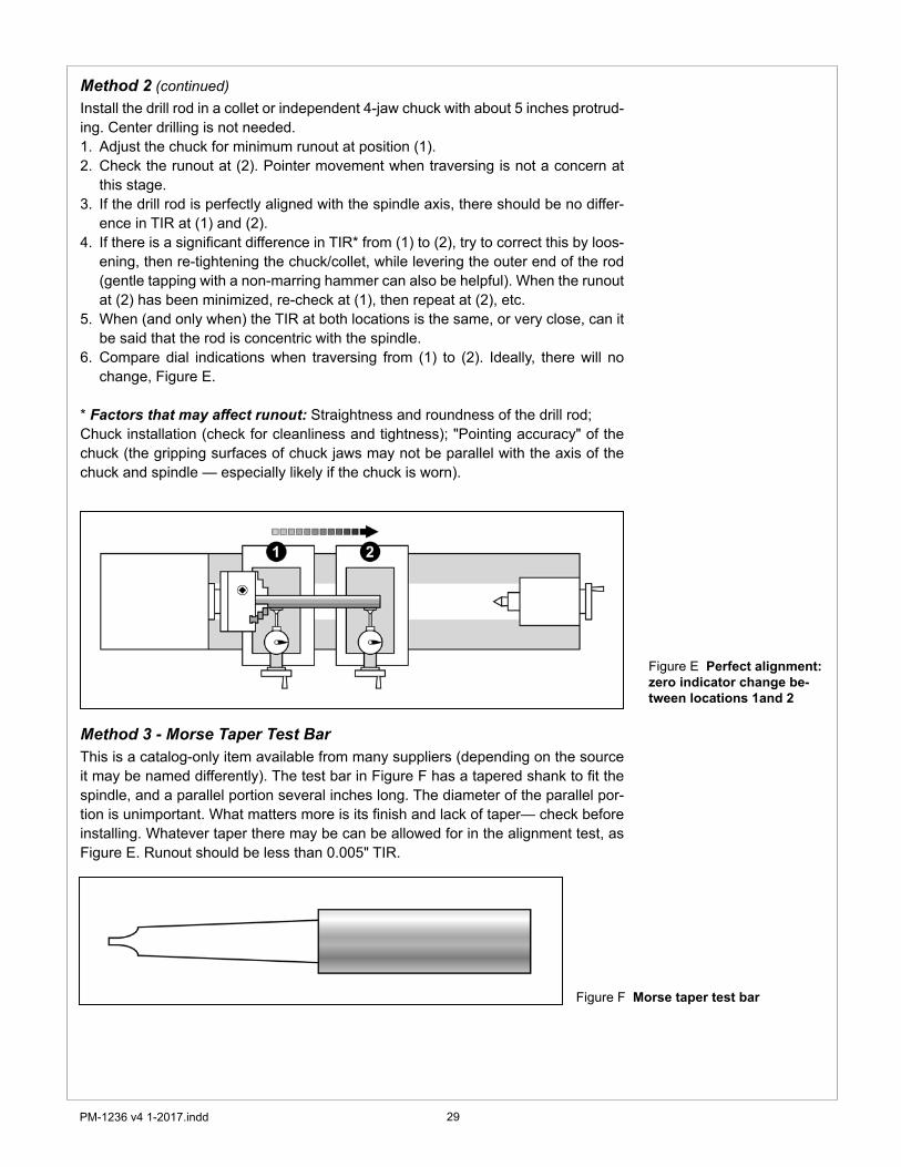
Method 2 (continued)Install the drill rod in a collet or independent 4-jaw chuck with about 5 inches protrud-ing. Center drilling is not needed.
Adjust the chuck for minimum runout at position (�).Check the runout at (2). Pointer movement when traversing is not a concern at this stage.If the drill rod is perfectly aligned with the spindle axis, there should be no differ-ence in TIR at (�) and (2).If there is a significant difference in TIR* from (�) to (2), try to correct this by loos-ening, then re-tightening the chuck/collet, while levering the outer end of the rod (gentle tapping with a non-marring hammer can also be helpful). When the runout at (2) has been minimized, re-check at (�), then repeat at (2), etc.When (and only when) the TIR at both locations is the same, or very close, can it be said that the rod is concentric with the spindle. Compare dial indications when traversing from (�) to (2). Ideally, there will no change, Figure E.
* Factors that may affect runout: Straightness and roundness of the drill rod; Chuck installation (check for cleanliness and tightness); "Pointing accuracy" of the chuck (the gripping surfaces of chuck jaws may not be parallel with the axis of the chuck and spindle — especially likely if the chuck is worn).
Method 3 - Morse Taper Test BarThis is a catalog-only item available from many suppliers (depending on the source it may be named differently). The test bar in Figure F has a tapered shank to fit the spindle, and a parallel portion several inches long. The diameter of the parallel por-tion is unimportant. What matters more is its finish and lack of taper— check before installing. Whatever taper there may be can be allowed for in the alignment test, as Figure E. Runout should be less than 0.005" TIR.
�.2.
3.
4.
5.
6.
Figure E Perfect alignment: zero indicator change be-tween locations 1and 2
Figure F Morse taper test bar
30PM-�236 v4 �-20�7.indd
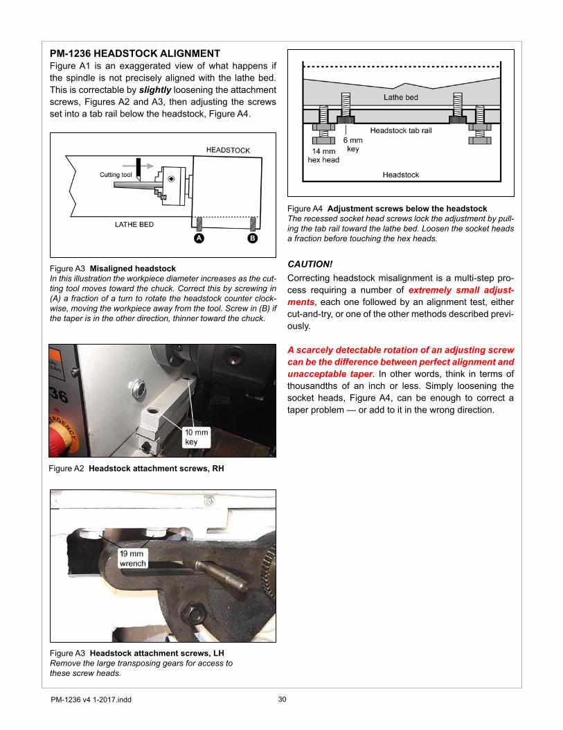
Figure A2 Headstock attachment screws, RH
Figure A3 Headstock attachment screws, LHRemove the large transposing gears for access to these screw heads.
Figure A4 Adjustment screws below the headstockThe recessed socket head screws lock the adjustment by pull-ing the tab rail toward the lathe bed. Loosen the socket heads a fraction before touching the hex heads.
PM-1236 HEADSTOCK ALIGNMENTFigure A� is an exaggerated view of what happens if the spindle is not precisely aligned with the lathe bed. This is correctable by slightly loosening the attachment screws, Figures A2 and A3, then adjusting the screws set into a tab rail below the headstock, Figure A4.
CAUTION!Correcting headstock misalignment is a multi-step pro-cess requiring a number of extremely small adjust-ments, each one followed by an alignment test, either cut-and-try, or one of the other methods described previ-ously.
A scarcely detectable rotation of an adjusting screw can be the difference between perfect alignment and unacceptable taper. In other words, think in terms of thousandths of an inch or less. Simply loosening the socket heads, Figure A4, can be enough to correct a taper problem — or add to it in the wrong direction.
Figure A3 Misaligned headstockIn this illustration the workpiece diameter increases as the cut-ting tool moves toward the chuck. Correct this by screwing in (A) a fraction of a turn to rotate the headstock counter clock-wise, moving the workpiece away from the tool. Screw in (B) if the taper is in the other direction, thinner toward the chuck.

3�PM-�236 v4 �-20�7.indd
Section 5 PARTS
Mdel PM-1236 Electrical schematic

32PM-�236 v4 �-20�7.indd
HEADSTOCK
Leve
r/pi
nion
ass
embl
y (q
ty 2
) fo
r C-B
-A a
nd 1
-2-3
gea
r shi
ft-er
s (#1
14 m
eshe
s with
#10
8)
Two
sets
of t
his a
ssem
bly:
C-B
-A
shift
er (L
H) a
nd 1
-2-3
shift
er (R
H)
Lead
scre
w d
irecti
on c
ontr
ol

33PM-�236 v4 �-20�7.indd
HEADSTOCK
Ref. Mfr. No. Description Qty. Ref. Mfr. No. Description Qty.1 2034 Spindle: D1-4 camlock, MT5 1 62 Key: 5 x 20 12 2035 Lock pin 3 63 2063 Plug 13 Spring: 0.6 × 4 × 22 3 64 Circlip 14 Screw: M8 x 16 skt hd 3 65 Ball bearing: 20 x 42 x 12 15 2038 End cap 1 66 2010B Shaft (input) 16 2006 Oil seal 1 67 Key: 5 x 80 17 D7212 Taper roller bearing 60 x 110 1 68 Key: 5 x 24 18 2031 Gear: 83T 1 69 2019 Gear: 47T 19 2030 Gear: 46T 1 70 2018 Gear: 23T 1
10 2029 Gear: 59T 1 71 2013 Gear: 42T 111 2024 Nut 1 72 47 Circlip 112 2008 Gear: 45T 1 73 Ball bearing: 25 x 47 x 12 213 D7211 Taper roller bearing 55 x 110 1 74 Circlip 114 2007 Nut, special 2 75 2012B Flange 115 2005A End cap 1 76 Oil seal: 25 x 40 x 10 116 2023 Oil seal 1 77 Screw: M6 x 20 skt hd 417 Screw: M8 x 16 skt hd 4 78 2014 Pulley 118 Screw: M8 x 8 set 2 79 2011 Washer 119 2025 Pin 2 80 Screw: M8 x 20 skt hd 120 Screw: M8 x 16 skt hd 4 81 Oil seal 121 Screw: M3 x 8 skt hd 2 82 Screw: M6 x 8 set 122 Key: 8 x 45 1 83 2001 Shaft, idler ** 123 Key: 8 x 80 1 84 Circlip 224 2037 Locking cam 3 85 2032 Gear: pair 40/45T 125 Screw: M8 x 16 skt hd 5 86 Ball bearing: 20 x 47 x 14 126 2040 End cap 1 87 Circlip 127 2028 Oil seal 1 88 Screw: M6 x 30 skt hd 628 Ball bearing: 20 x 52 x 15 1 89 Screw: M6 x 20 set 229 2039 Top shaft 1 90 Plug, oil drain, M16/1.5 130 2017 Gear: 21T 1 91 Oil seal: 16 x 2.4 131 Key: 5 x 18 2 92 Plug, oil fill, M16/1.5 132 2015 Gear: 58T 1 93 2044 Headstock cover 133 2016 Gear: 45T 1 94 2062 Oil seal 134 Circlip 1 95 2033 Headstock casting 135 2022 Gear: 31T 1 96 Pin: 4 x 24 236 2020 Gear: 55T 1 97 Oil seal: 16 x 2.4 737 2021 Gear: 36T 1 98 2046 Shaft, gear shifter 238 Circlip 1 99 2042 Crank 239 Ball bearing: 20 x 42 x 12 1 100 Pin: 4 x 24 340 2009 End cap 1 101 Circlip 341 2009A Oil seal 1 102 2041 Shoe, gear shift 242 Key: 8 x 10⁸ 1 103 Key: 5 x 16 243 Screw: M3 x 8 skt hd 2 104 2058 Shift lever 344 Oil seal 1 105 2059 Hub 245 2055 Faceplate 1 106 Steel ball: Ø5 446 Screw: M3 x 8 skt hd 6 107 Spring: 1 x 6 x 20 447 Screw: M6 x 12 skt hd 2 108 2047 Gear, meshes with 114 248 2003 Washer 2 109 Screw: M8 x 8 set 4
NOTEDimensions are in mil-limeters.All gears: pressure angle 20 degrees, module M2 (except item 59).Bearings: reference numbers in this list may not be recognized by stockists.If replacing a bearing or oil seal, remove and measure the item in question. Order re-placement parts from Quality Machines.

34PM-�236 v4 �-20�7.indd
HEADSTOCK (continued)
49 2026 Gear: pair 40/45T 2 110 Screw: M12 x 25 skt hd 250 25 Circlip 1 111 Screw: M3 x 6 skt hd 451 Ball bearing: 25 x 47 x 12 1 112 2060 Pointer disk 252 2027A Shaft (output) 1 113 Screw: M6 x 20 set 253 42 Circlip 1 114 2061 Gear, meshes with 108 254 Ball bearing: 20 x 42 x 12 1 115 Screw: M6 x 8 set 155 20 Circlip 1 116 2054A Crank 156 Oil seal: 20 × 40 × 10 1 117 2079 Collar 157 2004A Flange 1 118 2048 Shoe, forward/reverse 158 2066 Oil seal 2 119 2052 Shaft, leadscrew fwd/rev** 159 Gear: M1.25 (external)* 1 120 Pin: 5 x 30 160 Screw: M6 x 12 skt hd 3 121 2051 Hub 161 Key: 5 x 8 1 ** #83, #119, and related items, select fwd. or rev.
* Gear size depends on pitch of thread being cut leadscrew rotation relative to the spindle
CHANGE GEARS
NOTEGear sizes shown are for illustration. Actual sizes of the headstock output gear and carriage feed input gear depend on the thread pitch or carriage feed rate desired. Order replacement gears by tooth count.
35PM-�236 v4 �-20�7.indd
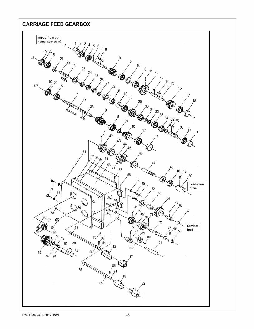
CARRIAGE FEED GEARBOX
Input (from ex-ternal gear train)
Leadscrew drive
Carriage feed

36PM-�236 v4 �-20�7.indd
CARRIAGE FEED GEARBOXNOTEDimensions are in mil-limeters.All gears: pressure angle 20 degrees, module M2.25.Bearings: reference numbers in this list may not be recognized by stockists.If replacing a bearing or oil seal, remove and measure the item in question. Order replace-ment parts from Quality Machines.
Ref. Mfr. No. Description Qty. Ref. Mfr. No. Description Qty.1 Oiler 1 51 3060E Front panel 12 Screw: M6 x 12 skt hd 7 52 3071D Oil seal 13 3034B Input shaft (1) flange 1 53 3059D Faceplate 14 3035C Oil seal 1 54 3042C Back plate 15 89103 Ball bearing: 17 x 35 x 10 8 55 3070C Oil seal 16 Key: 5 x13 1 56 3001C Gearbox casting 17 3041B Input shaft (1) 1 57 Screw: M6 x 12 skt hd 68 Key: 6 x 90 3 58 Pin: 5 x 25 29 3005B Gear: triple, 18/X/18 2 59 Washer: M10, spring 2
10 3066B Spacer 2 60 Screw: M10 x 30 skt hd 211 Screw: M6 x 8 set 1 61 Screw: M6 x 12 skt hd 112 3027C Gear: 27T 1 62 Spacer: 6 x 32 x 5 113 Key: 6 x 15 1 63 B1260 Bushing 114 Key: 6 x 35 1 64 3016C Gear: 17T 115 3067B Shaft 1 65 Screw: M6 x 16 set 116 3025C Gear: 21T 1 66 3015C Shaft 117 89102 Ball bearing: 15 x 32 x 9 3 67 Oil seal: 22 x 2.65 118 3017B Plug 3 68 3014C Gear: 15T 119 3044B Shaft end cap 2 69 3022F Sleeve 120 3046B Oil seal 2 70 3086D Oil seal 121 3045B Bushing 1 71 Screw: M6 x 25 skt hd 522 3033B Shaft (2) 1 72 3013E Shaft 123 3029B Gear: 24T 1 73 Oil seal: 18 x 30 x 10 124 3031B Gear: 16T 1 74 Plug, oil fill, M16/1.5 225 3032B Gear: 18T 1 75 Oil seal: 16 x 2.4 226 3003B Gear: 20T 1 76 Screw: M8 x 15 skt hd 827 3030B Spacer 1 77 Screw: M6 x 10 set 128 3002B Gear: 28T 1 78 3012D Bushing 129 3026C Gear: pair 18T/30T 1 79 7003B Support bracket 130 3007C Gear: 22T 1 80 Screw: M4 x 20 skt hd 231 3008C Spacer 1 81 3011D Shaft 132 Circlip 2 82 3050C Shift fork 133 89103 Ball bearing: 17x 35 x 10 1 83 3049C Shift fork 234 3009B Gear: 23T 1 84 3089A Shaft, gear shifters 235 Key: 5 x 40 1 85 O-ring seal: 12 x 1.8 436 3019C Shaft 1 86 Screw: M4 × 6 set 237 3004B Shaft (3) 1 87 3062C Shift fork 138 Key: 5 x 35 1 88 Screw: M3 x 6 skt hd 1239 Circlip 1 89 2060 Pointer disk 440 3006C Gear: pair 15T/22T 1 90 Screw: M8 × 6 set 441 Pin: 5 x 6 2 91 Spring: 1 x 5 x 25 442 3018C Gear: 21T 1 92 Steel ball: Ø5 443 8103 Thrust bearing: 17 x 32 x 8 1 93 Screw: M6 x 10 skt hd 444 3084D Leadscrew flange 1 94 Washer 445 3068D Oil seal 1 95 3054F Knurled knob 446 8104 Thrust bearing: 20 x 35 x 10 1 96 Key: 5 x 8 447 3021C Shaft. leadscrew drive 1 97 3088 Gear, shift fork drive 448 Nut: M20 x 1.5, special 2 98 A12 Sight glass 149 Pin: 5 x 6 1 99 O-ring seal: 16 x 2.4 450 3020E Leadscrew connector 1
37PM-�236 v4 �-20�7.indd
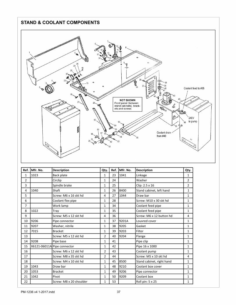
STAND & COOLANT COMPONENTS
Ref. Mfr. No. Description Qty. Ref. Mfr. No. Description Qty.1 1023 Back plate 1 23 1041 Linkage 12 Circlip 1 24 Washer 23 Spindle brake 1 25 Clip: 2.5 x 16 24 1040 Shaft 1 26 8400 Stand cabinet, left hand 15 Screw: M6 x 16 skt hd 4 27 1044 Draw bar 16 Coolant flex pipe 1 28 Screw: M10 x 30 skt hd 17 Work lamp 1 34 Coolant feed pipe 18 1022 Tray 1 35 Coolant feed pipe 19 Screw: M5 x 12 skt hd 4 36 Screw: M6 x 12 button hd 4
10 9206 Pipe connector 1 37 9201A Louvred cover 111 9207 Washer, nitrile 1 38 9205 Gasket 112 7015 Bracket 1 39 9203 Filter 113 Screw: M5 x 12 skt hd 2 40 9204 Flange 114 9208 Pipe base 1 41 Pipe clip 115 X6121-06011A Pipe connector 1 42 Pipe 16 x 1000 116 Screw: M6 x 12 skt hd 2 43 Coolant pump 117 Screw: M8 x 35 skt hd 2 44 Screw: M5 x 10 skt hd 418 Screw: M4 x 10 skt hd 1 45 8500 Stand cabinet, right hand 119 1043 Draw bar 1 48 9210 Coolant box cover 120 1053 Bracket 1 49 9206 Pipe connector 121 1042 Pivot 1 50 9209 Coolant box 122 Screw: M8 x 20 shoulder 1 53 Roll pin: 5 x 25 1

38PM-�236 v4 �-20�7.indd
STAND & COOLANT COMPONENTS (continued)
Ref. Mfr. No. Description Qty. Ref. Mfr. No. Description Qty.54 1048 Spring, extension 1 61 Roll pin: 5 x 40 155 1047 Spring anchor 1 62 1049-1 Shaft 156 Collar: 20 ID 1 63 Screw: M6 x 12 skt hd 157 1045 Crank 1 64 1049-3 Connecting sleeve 158 1052 Stop post 1 65 1049-2 Brake shaft 159 Stop screw, M6 x 30 1 66 1050 Brake treadle 160 1054 Draw bar 1
MOTOR MOUNT & COVER
Ref. Mfr. No. Description Qty. Ref. Mfr. No. Description Qty.1 1021 Cover 1 9 Screw: M6 x 8 set 12 1002 Threaded stud 2 10 Motor 13 1001 Knurled nut 2 11 Washer 44 1024 Motor mount 1 12 Screw 45 1013 Washer 3 13 Nut: M6 26 Screw 3 14 Screw: M8 x 45 hex hd 27 Key: 8 x 40 1 15 Screw: M8 x 30 hex hd 28 1003A5 Double pulley 1

39PM-�236 v4 �-20�7.indd
TAILSTOCK
Ref. Mfr. No. Description Ref. Mfr. No. Description1 4033 Shoulder bolt 17 6012 Nut: M102 4032 18 6013 Tailstock quill3 Nut: M10 19 6001 Tailstock body4 Washer 20 6022 Clamp screw5 6005 Handwheel 21 6021 Lever6 4037 Leaf spring 22 6017 Clamp screw7 6010 Graduated collar 23 6004 Lever8 Screw: M6 x 16 24 Pin: 5 x 309 6011 Flange 25 6018 Collar (cam)
10 Oiler 26 Screw: M10 x 5011 Thrust bearing: 12 x 26 x 8 27 6003 Screw12 Key: 4 x 15 28 6002 Tailstock base13 6006 Tailstock leadscrew 29 6019 Pull rod14 6023 Nut: M10 30 6020 Shoe15 Oiler 31 Nut: M1216 Screw: M6 x 8

40PM-�236 v4 �-20�7.indd
COMPOUND REST
Ref. Mfr. No. Description Qty. Ref. Mfr. No. Description Qty.1 5010 Clamp lever 1 19 5023 Compound rest gib 12 5009 Clamp boss, M16 1 20 5021 Gib screw 23 5008 Collar 1 21 5012A1 Leadscrew barrel nut 14 Screw: sq hd, M10 x 45 8 22 5011A3 Compound rest leadscrew 15 5005 4-way toolholder 1 23 Key: 4 x 8 16 5006 Tool post bolt, M16 1 24 8101 Thrust bearing: 12 x 26 x 9 17 5003 Slide T-nut 1 25 5026A2 Datum plate 18 5004 Detent pin 1 26 Rivet: 2 x 4 29 Spring, comp. 1.2 x 4.8 x 8 1 27 Screw: skt hd, M6 x 25 2
10 Oiler 1 28 5013 Leadscrew flange 111 Nut: M6 1 29 8101 Thrust bearing: 12 x 26 x 9 112 Screw: set, M6 x 16 1 30 5014A3 Graduated collar 113 5001 Compound swivel base 31 5016A Handwheel 114 5107 T-bolt, M10 2 32 5028 Washer 115 Nut: M10 2 33 Screw: skt hd, M6 x 12 116 5002 Compound rest 34 5031 Handle (pr., diff. lengths) 217 5024 Pressure pin 35 4037 Leaf spring 118 Screw: set, M6 x 8

4�PM-�236 v4 �-20�7.indd
CARRIAGE (diagram on following page)
Ref. Mfr. No. Description Qty. Ref. Mfr. No. Description Qty.1 5101 Carriage 24 Nut: M8 42 Screw: M5 x 12 8 25 Screw: M8 x 25 skt hd 43 5108 Wiper 1 26 5112 Wiper cover 24 5106 Wiper cover 1 27 5111 Wiper 25 Screw: M3 x 8 1 28 5131 Gib support bar 16 5130 Carriage gib 2 29 5116 Slider plate 27 5110 Wiper cover 2 30 Key: 5 x 20 18 5109 Wiper 2 31 5129 Carriage lock plate 19 5113 Screw: oil cap 1 32 Pin: 3 x 20 1
10 5128 Screw: carriage locking 1 33 5124A3 Graduated collar 111 Pin: 6 x 45 2 34 4037 Leaf spring 112 Screw: M10 x 30 skt hd 4 35 5122A Handwheel 113 Oiler 5 36 5028 Washer 114 5115 Cross slide gib screw 2 37 Screw: M6 x 16 skt hd 115 5102 Cross slide 1 38 4033 Shoulder bolt 116 Screw: M6 x 12 1 39 4032 Handle 117 5105 Bushing 1 40 8102 Thrust bearing: 15 x 28 x 9 118 5114 Cross slide gib 1 41 5125A Leadscrew hub 119 Screw: M4 x 12 1 42 Screw: M8 x 30 skt hd 220 5104A2 Split nut 1 43 5126 Collar 121 Gear 1 44 5103A3 Cross slide leadscrew 122 Screw: M6 x 8 set 1 45 Rivet: 2 x 4 223 Screw: M8 x 25 skt hd 7 46 5133A2 Datum plate 1
LATHE BED
Lathe bed 10047
NOTE Racks are attached by M6 x 15 skt hd screws (6) and 5 x 20 pins (6). Bed is attached to stands by M12 x 40 hex hd bolts (6)
NOT SHOWN Removable gap plug and related hardware

42PM-�236 v4 �-20�7.indd
CARRIAGE (continued)
43PM-�236 v4 �-20�7.indd
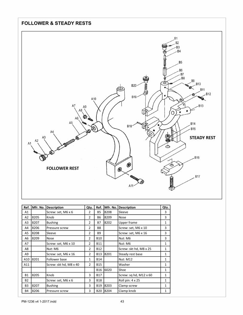
FOLLOWER & STEADY RESTS
Ref. Mfr. No. Description Qty. Ref. Mfr. No. Description Qty.A1 Screw: set, M6 x 6 2 B5 8208 Sleeve 3A2 8205 Knob 2 B6 8209 Nose 3A3 8207 Bushing 2 B7 8202 Upper frame 1A4 8206 Pressure screw 2 B8 Screw: set, M6 x 10 3A5 8208 Sleeve 2 B9 Screw: set, M6 x 16 3A6 8209 Nose 2 B10 Nut: M6 3A7 Screw: set, M6 x 10 2 B11 Nut: M6 1A8 Nut: M6 2 B12 Screw: skt hd, M8 x 25 1A9 Screw: set, M6 x 16 2 B13 8201 Steady rest base 1
A10 8201 Follower base 1 B14 Nut: M12 1A11 Screw: skt hd, M8 x 40 2 B15 Washer 1
B16 6020 Shoe 1B1 8205 Knob 3 B17 Screw: sq hd, M12 x 60 1B2 Screw: set, M6 x 6 3 B18 Roll pin: 4 x 25 1B3 8207 Bushing 3 B19 8203 Clamp screw 1B4 8206 Pressure screw 3 B20 8204 Clamp knob 1
STEADY REST
FOLLOWER REST

44PM-�236 v4 �-20�7.indd
APRON
Not shown Oil sight glass
Ref. Mfr. No. Description Qty. Ref. Mfr. Description Qty.1 4026 Bushing 1 28 4014 Gear: 25T2 4029 Gear: 50T 1 29 4016 Hub3 Pin: 5 x 30 1 30 4001 Apron case4 4027 Spacer 1 31 Screw: set M6 x 6 15 4028 Gear shaft: 11T 1 32 4010 Gear: 25T 16 4008 Worm bracket 1 33 4011 Shaft 17 4009 Worm 1 34 Screw: skt hd M6 x 45 38 Key: 5 x 36 1 35 Screw: set M8 x 8 19 4032 Handle 1 36 Spring: 1 x 45 x 6 2
10 4033 Shoulder bolt 1 37 Ball 211 4034 Handwheel 1 38 4041 Lever 112 4036 Graduated collar 1 39 4042 Splined shaft 113 Screw: skt hd M6 x 20 2 40 Pin: 5 x 25 114 4031 Hub 41 4020 Bushing 115 Oiler 42 4019 Gear: 14T 116 4030 Gear shaft: 15T 43 Pin: 5 x 25 117 Screw: skt hd M6 x 12 1 44 4018 Shaft 118 4035 Washer 1 45 4017 Worm gear, 24T 119 Screw: skt hd M6 x 10 4 47 Screw: set M5 x 33 220 4038 Washer 1 49 Screw: skt hd M6 x 10 121 4039 Post 1 50 Screw: set M6 x 6 122 Key: 5 x 16 1 51 4043 Limit stop 123 4037 Leaf spring 1 52 4025 Lock collar 124 4015 Shaft, power feed select 53 4024 Shaft 125 4012 Gear: 48T 54 Screw: set M8 x 8 126 Pin: 5 x 33 1 55 4045 Boss, split-nut shaft 127 4013 Gear: 51T 56 Pin: 5 x 40 1
Worm rides on feed shaft, not shown, drives gear #45
#52, #57 and related components prevent accidental closing of the half nuts #70 when cross slide feed or carriage feed is engaged by lever #39
Splines on #39 engage with grooves on #24

45PM-�236 v4 �-20�7.indd
CARRIAGE STOP
MOTOR CONTROL
Motor switches at left end of control shaft, front cover removed
Motor switches, end-on from left, showing D-shape cam attached to end of control shaft
APRON (continued)
Ref. Mfr. No. Description Qty. Ref. Mfr. Description Qty.57 4021 Stop flag 1 67 3022 Gib, split-nut casing 258 Screw: set M5 x 12 1 69 Screw: skt hd M5 259 4023 Split-nut shaft 1 70 Split-nut assembly 160 Screw: skt hd M8 x 30 1 72 Set screw 261 Washer 2 73 Nut 262 Screw: skt hd M10 x 20 2 74 4006 Threading dial 163 Washer 1 75 4005 Housing 164 Nut: M6 1 76 Screw: skt hd M6 x 65 165 4044 Lever, split-nut shaft 1 77 4044 Gear, leadscrew follower, 16T 166 Pin: 5 x 10 2 78 Screw: M6 x 15 1
COOLANT PUMP WIRING