MODEL PG-F255W - Sharp Australia Supportsupport.sharp.net.au/downloads/opmanuals/PGF255Wom.pdf ·...
70
Introduction Quick Start Setup Connections Basic Operation Useful Features Appendix OPERATION MANUAL DATA PROJECTOR MODEL PG-F255W
Transcript of MODEL PG-F255W - Sharp Australia Supportsupport.sharp.net.au/downloads/opmanuals/PGF255Wom.pdf ·...

Intro
du
ction
Qu
ick Start
Setu
pC
on
nectio
ns
Basic
Op
eration
Usefu
lF
eatures
Ap
pen
dix
OPERATION MANUAL
DATA PROJECTORMODEL
PG-F255W

ii
IMPORTANT• For your assistance in reporting the loss
or theft of your Projector, please recordthe Model and Serial Number located onthe bottom of the projector and retain thisinformation.
• Before recycling the packaging, pleaseensure that you have checked the con-tents of the carton thoroughly against thelist of “Supplied accessories” on page 11.
Model No.:
Serial No.:

iii
SPECIAL NOTE FOR USERS IN THE U.K.The mains lead of this product is fitted with a non-rewireable (moulded) plug incorporat-ing a 10A fuse. Should the fuse need to be replaced, a BSI or ASTA approved BS 1362fuse marked or and of the same rating as above, which is also indicated on the pinface of the plug, must be used.Always refit the fuse cover after replacing the fuse. Never use the plug without the fusecover fitted.In the unlikely event of the socket outlet in your home not being compatible with the plugsupplied, cut off the mains plug and fit an appropriate type.
DANGER:The fuse from the cut-off plug should be removed and the cut-off plug destroyed immedi-ately and disposed of in a safe manner.Under no circumstances should the cut-off plug be inserted elsewhere into a 13A socketoutlet, as a serious electric shock may occur.To fit an appropriate plug to the mains lead, follow the instructions below:
WARNING:THIS APPARATUS MUST BE EARTHED.IMPORTANT:The wires in this mains lead are coloured in accordance with the following code:
Green-and-yellow : EarthBlue : NeutralBrown : Live
As the colours of the wires in the mains lead of this apparatus may not correspond with thecoloured markings identifying the terminals in your plug proceed as follows:• The wire which is coloured green-and-yellow must be connected to the terminal in the
plug which is marked by the letter E or by the safety earth symbol or coloured green orgreen-and-yellow.
• The wire which is coloured blue must be connected to the terminal which is marked withthe letter N or coloured black.
• The wire which is coloured brown must be connected to the terminal which is marked withthe letter L or coloured red.
IF YOU HAVE ANY DOUBT, CONSULT A QUALIFIED ELECTRICIAN.

iv
The supplied CD-ROM contains operation instructions in English, German, French,Spanish, Italian, Dutch, Swedish, Portuguese and Chinese. Carefully read through theoperation instructions before operating the projector.
Die mitgelieferte CD-ROM enthält Bedienungsanleitungen in Englisch, Deutsch, Französisch,Spanisch, Italienisch, Niederländisch, Schwedisch, Portugiesisch und Chinesisch. Bitte lesenSie die Bedienungsanleitung vor der Verwendung des Projektors sorgfältig durch.
Le CD-ROM fourni contient les instructions de fonctionnement en anglais, allemand,français, espagnol, italien, néerlandais, suédois, portugais et chinois. Veuillez lireattentivement ces instructions avant de faire fonctionner le projecteur.
El CD-ROM suministrado contiene instrucciones de operación en inglés, alemán,francés, español, italiano, holandés, sueco, portugués y chino. Lea cuidadosamente lasinstrucciones de operación antes de utilizar el proyector.
Il CD-ROM in dotazione contiene istruzioni per l’uso in inglese, tedesco, francese,spagnolo, italiano, olandese, svedese, portoghese e cinese. Leggere attentamente leistruzioni per l’uso prima di usare il proiettore.
De meegeleverde CD-ROM bevat handleidingen in het Engels, Duits, Frans, Spaans,Italiaans, Nederlands, Zweeds, Portugees en Chinees. Lees de handleiding zorgvuldigdoor voor u de projector in gebruik neemt.
Den medföljande CD-ROM-skivan innehåller bruksanvisningar på engelska, tyska,franska, spanska, italienska, holländska, svenska, portugisiska och kinesiska. Läs nogaigenom bruksanvisningen innan projektorn tas i bruk.
O CD-ROM fornecido contém instruções de operação em Inglês, Alemão, Francês,Espanhol, Italiano, Holandês, Sueco, Português e Chinês. Leia cuidadosamente todas asinstruções de operação antes de operar o projetor.

1
Intro
du
ction
Before using the projector, please read this operation manual carefully.
There are two important reasons for prompt warranty registration of your new SHARPProjector, using the REGISTRATION CARD packed with the projector.
1. WARRANTYThis is to assure that you immediately receive the full benefit of the parts, serviceand labor warranty applicable to your purchase.
2. CONSUMER PRODUCT SAFETY ACTTo ensure that you will promptly receive any safety notification of inspection,modification, or recall that SHARP may be required to give under the 1972Consumer Product Safety Act, PLEASE READ CAREFULLY THE IMPORTANT“LIMITED WARRANTY” CLAUSE.
WARNING: High brightness light source. Do not stare into the beam of light, or viewdirectly. Be especially careful that children do not stare directly into thebeam of light.
WARNING: To reduce the risk of fire or electric shock, do not exposethis product to rain or moisture.
WARNING: FCC Regulations state that any unauthorized changes or modifications tothis equipment not expressly approved by the manufacturer could voidthe user’s authority to operate this equipment.
The lightning flash with arrowhead sym-bol, within an equilateral triangle, is in-tended to alert the user to the presenceof uninsulated “dangerous voltage”within the product’s enclosure that maybe of sufficient magnitude to constitutea risk or electric shock to persons.
The exclamation point within a triangleis intended to alert the user to thepresence of important operating andmaintenance (servicing) instructions inthe literature accompanying the product.
Introduction ENGLISH
See bottom of projector.
U.S.A. ONLY
U.S.A. ONLY
CAUTION: TO REDUCE THE RISK OF ELECTRIC SHOCK,DO NOT REMOVE COVER.
NO USER-SERVICEABLE PARTS EXCEPT LAMP UNIT.REFER SERVICING TO QUALIFIED SERVICE
PERSONNEL.
CAUTIONRISK OF ELECTRIC SHOCK.DO NOT REMOVE SCREWSEXCEPT SPECIFIED USER
SERVICE SCREW.
2
Caution Concerning Lamp ReplacementSee “Replacing the Lamp” on page 55.
This SHARP projector uses a DLP® chip. This very sophisticated panel contains 1,024,000pixels (micromirrors). As with any high technology electronic equipment such as large screenTVs, video systems and video cameras, there are certain acceptable tolerances that theequipment must conform to.This unit has some inactive pixels within acceptable tolerances which may result in inactive dotson the picture screen. This will not affect the picture quality or the life expectancy of the unit.
INFORMATIONThis equipment has been tested and found to comply with the limits for a Class Adigital device, pursuant to Part 15 of the FCC Rules. These limits are designed toprovide reasonable protection against harmful interference when the equipmentis operated in a commercial environment. This equipment generates, uses, andcan radiate radio frequency energy and, if not installed and used in accordancewith the operation manual, may cause harmful interference to radiocommunications. Operation of this equipment in a residential area is likely tocause harmful interference, in which case the user will be required to correct theinterference at his own expense. U.S.A. ONLY
Authorized representative responsible for the European Union Community Market
SHARP ELECTRONICS (Europe) GmbHSonninstraße 3, D-20097 Hamburg E.U. ONLY
The enclosed computer cable must be used with the device. The cable isprovided to ensure that the device complies with FCC Class A verification.
U.S.A. ONLY
WARNING:This is a Class A product. In a domestic environment this product may causeradio interference in which case the user may be required to take adequatemeasures.
PRODUCT DISPOSALThis product utilizes tin-lead solder, and lamp containing a small amountof mercury. Disposal of these materials may be regulated due toenvironmental considerations. For disposal or recycling information,please contact your local authorities, the Electronics Industries Alliance:www.eiae.org, the lamp recycling organization www.lamprecycle.org,or Sharp at 1-800-BE-SHARP. U.S.A. ONLY

3
Intro
du
ction
39
Usefu
lF
eatures
Menu Selections (Adjustments)
Example: Adjusting “Bright”.• This operation can also be performed by using the buttons on the projector.
Press MENU/HELP.• The “Picture” menu screen for the se-
lected input mode is displayed.
Example: “Picture” screen menu forCOMPUTER (RGB) input
Press Q or O and select “Picture”to adjust.
1
2Menu item
Picture ModeContrast 0
00
Bright
Standard
SEL./ADJ. ENTER END
00
RedBlueCLR TempBrilliantColorTM
C.M.S. SettingC.M.S.
Lamp Setting
01
On
Bright
DNR Off
Reset
Picture SCR PRJ Net. Help
Adjustment buttons (P/R/O/Q)
MENU/HELP button
ENTER button
Adjustment buttons(P/R/O/Q)
ENTER button
RETURN button• Press RETURN to return
to the previous screenwhen the menu isdisplayed.
MENU/HELP button
Using the Menu Screen
How to Read this Operation Manual
■ The specifications are slightly different, depending on the model. However, you can connect andoperate all models in the same manner.
• In this operation manual, the illustration and the screen display are simplified for explanation, andmay differ slightly from the actual display.
Info ....... Indicates safeguards for using the projector.
Note ....... Indicates additional information for setting up and operating theprojector.
For Future Reference
Buttons used inthis operation
On-screendisplay
Button used inthis step
IndexMaintenance Troubleshooting
P. 65P. 52 PP. 60 and 61

4
Contents
Preparing
IntroductionHow to Read this Operation Manual .... 3Contents ............................................... 4IMPORTANT SAFEGUARDS ............... 6How to Access the PDF Operation
Manuals ............................................ 10Accessories ........................................ 11Part Names and Functions ................. 12
Projector ............................................... 12Rear View ............................................. 13Inserting the Batteries .......................... 15Usable Range ...................................... 15
Quick StartQuick Start .......................................... 16
Setup and Projection ............................ 16
SetupSetting up the Projector ...................... 18
Setting up the Projector ....................... 18Standard Setup (Front Projection) ....... 18Ceiling-mount Setup ............................ 18Projection (PRJ) Mode ......................... 19Screen Size and Projection Distance .. 20
ConnectionsConnecting the Projector to
Other Equipment .............................. 21Controlling the Projector by
a Computer ....................................... 24Connecting the Power Cord ............... 25
Useful FeaturesOperating with the Remote Control .... 33
Displaying and Setting theBreak Timer ........................................ 33
Displaying the Pointer .......................... 33Using the Spot Function ...................... 33Switching the Eco+Quiet Mode ........... 33Auto Sync (Auto Sync Adjustment) ..... 34Freezing a Moving Image .................... 34Selecting the Picture Mode .................. 34Displaying an Enlarged Portion of
an Image ............................................ 34Using the Remote Control as the
Wireless Computer Mouse ................ 35Menu Items ......................................... 36Using the Menu Screen ...................... 39
Menu Selections (Adjustments) ........... 39Picture Adjustment (“Picture” Menu) ... 41
Selecting the Picture Mode .................. 41Adjusting the Image ............................. 42Adjusting the Color Temperature ......... 42Adjusting the Colors ............................. 42Progressive ........................................... 43Reducing Image Noise (DNR) ............. 43Lamp Setting ........................................ 43
Adjusting the Projected Image(“SCR - ADJ” Menu) ......................... 44Setting the Resize Mode ...................... 44Adjusting the Image Position ............... 44Keystone Correction ............................ 44Setting the On-screen Display ............. 44Selecting the Background Image ........ 45Selecting the Setup Guide ................... 45Reversing/Inverting Projected
Images ............................................... 45Selecting the On-screen Display
Language ........................................... 45Adjusting the Projector Function
(“PRJ - ADJ” Menu) .......................... 46Auto Sync (Auto Sync Adjustment) ..... 46Auto Power Off Function ...................... 46Auto Restart Function .......................... 46STANDBY Mode ................................... 46Setting the Confirmation Sound
(System Sound) ................................. 46Speaker Setting .................................... 46Audio Input ........................................... 47Selecting the Transmission Speed
(RS-232C) .......................................... 47Fan Mode Setting ................................. 47System Lock Function .......................... 47Checking the Lamp Life Status ........... 48Keylock Function .................................. 48
Using
Basic OperationTurning the Projector On/Off .............. 26
Turning the Projector on ....................... 26Turning the Power off (Putting the
Projector into Standby Mode) ........... 26Image Projection ................................. 27
About the Setup Guide ........................ 27Adjusting the Projected Image ............ 27Correcting Trapezoidal Distortion ........ 29Switching the Input Mode .................... 30Adjusting the Volume ........................... 30Displaying the Black Screen and
Turning off the Sound Temporarily .... 30Resize Mode ......................................... 31
5
Intro
du
ction
Setting up the Projector NetworkEnvironment (“Network” menu) ........ 49Setting a Password .............................. 49DHCP Client Setting ............................. 50TCP/IP Setting ...................................... 50Confirming the Projector Information ... 50
Troubleshooting with the“Help” Menu ...................................... 51Utilizing the “Help” Menu Functions .... 51
AppendixMaintenance ....................................... 52Maintenance Indicators ...................... 53Regarding the Lamp ........................... 55
Lamp ..................................................... 55Caution Concerning the Lamp ............ 55Replacing the Lamp ............................. 55Removing and Installing the
Lamp Unit .......................................... 56Resetting the Lamp Timer .................... 57
Storing the Projector ........................... 58How to Use the Storage Case ............. 58
Computer Compatibility Chart ............ 59Troubleshooting .................................. 60For SHARP Assistance ...................... 62Specifications ..................................... 63Dimensions ......................................... 64Index ................................................... 65
Reference

6
1. Read InstructionsAll the safety and operating instructions shouldbe read before the product is operated.
2. Retain InstructionsThe safety and operating instructions should beretained for future reference.
3. Heed WarningsAll warnings on the product and in the operatinginstructions should be adhered to.
4. Follow InstructionsAll operating and use instructions should befollowed.
5. CleaningUnplug this product from the wall outlet beforecleaning. Do not use liquid cleaners or aerosolcleaners. Use a damp cloth for cleaning.
6. AttachmentsDo not use attachments not recommended by theproduct manufacturer as they may cause hazards.
7. Water and MoistureDo not use this product near water–for example,near a bath tub, wash bowl, kitchen sink, orlaundry tub; in a wet basement; or near aswimming pool; and the like.
8. AccessoriesDo not place this product on an unstable cart,stand, tripod, bracket, or table. The product mayfall, causing serious injury to a child or adult, andserious damage to the product. Use only with acart, stand, tripod, bracket, or tablerecommended by the manufacturer, or sold withthe product. Any mounting of the product shouldfollow the manufacturer’s instructions, and shoulduse a mounting accessory recommended by themanufacturer.
9. TransportationA product and cartcombination should bemoved with care. Quickstops, excessive force,and uneven surfaces maycause the product and cartcombination to overturn.
IMPORTANT SAFEGUARDS
10. VentilationSlots and openings in the cabinet are providedfor ventilation to ensure reliable operation of theproduct and to protect it from overheating, andthese openings must not be blocked or covered.The openings should never be blocked by placingthe product on a bed, sofa, rug, or other similarsurface. This product should not be placed in abuilt-in installation such as a bookcase or rackunless proper ventilation is provided or themanufacturer’s instructions have been adheredto.
11. Power SourcesThis product should be operated only from thetype of power source indicated on the markinglabel. If you are not sure of the type of powersupply to your home, consult your product dealeror local power company. For products intendedto operate from battery power, or other sources,refer to the operating instructions.
12. Grounding or PolarizationThis product is provided with one of the followingtypes of plugs. If the plug should fail to fit into thepower outlet, please contact your electrician.Do not defeat the safety purpose of the plug.a. Two-wire type (mains) plug.b. Three-wire grounding type (mains) plug with
a grounding terminal.This plug will only fit into a grounding typepower outlet.
13. Power-Cord ProtectionPower-supply cords should be routed so that theyare not likely to be walked on or pinched by itemsplaced upon or against them, paying particularattention to cords at plugs, conveniencereceptacles, and the point where they exit fromthe product.
14. LightningFor added protection for this product during alightning storm, or when it is left unattended andunused for long periods of time, unplug it fromthe wall outlet and disconnect the cable system.This will prevent damage to the product due tolightning and power-line surges.
CAUTION: Please read all of these instructions before you operate this productand save these instructions for later use.
Electrical energy can perform many useful functions. This product has been engineeredand manufactured to assure your personal safety. BUT IMPROPER USE CAN RESULT INPOTENTIAL ELECTRICAL SHOCK OR FIRE HAZARDS. In order not to defeat thesafeguards incorporated in this product, observe the following basic rules for its installation,use and servicing.
7
Intro
du
ction
15. OverloadingDo not overload wall outlets, extension cords, orintegral convenience receptacles as this canresult in a risk of fire or electric shock.
16. Object and Liquid EntryNever push objects of any kind into this productthrough openings as they may touch dangerousvoltage points or short-out parts that could resultin a fire or electric shock. Never spill liquid of anykind on the product.
17. ServicingDo not attempt to service this product yourself asopening or removing covers may expose you todangerous voltage or other hazards. Refer allservicing to qualified service personnel.
18. Damage Requiring ServiceUnplug this product from the wall outlet and referservicing to qualified service personnel under thefollowing conditions:a. When the power-supply cord or plug is
damaged.b. If liquid has been spilled, or objects have fallen
into the product.c. If the product has been exposed to rain or
water.d. If the product does not operate normally by
following the operating instructions. Adjust onlythose controls that are covered by theoperating instructions, as an improperadjustment of other controls may result indamage and will often require extensive workby a qualified technician to restore the productto normal operation.
e. If the product has been dropped or damagedin any way.
f. When the product exhibits a distinct changein performance, this indicates a need forservice.
• DLP® and the DLP logo are registered trademarks of Texas Instruments and BrilliantColorTM
is a trademark of Texas Instruments.• Microsoft® and Windows® are registered trademarks of Microsoft Corporation in the United
States and/or other countries.• PC/AT is a registered trademark of International Business Machines Corporation in the
United States.• Adobe® Reader® is a trademark of Adobe Systems Incorporated.• Macintosh® is a registered trademark of Apple Computer, Inc. in the United States and/or
other countries.• PJLink is a registered trademark or an application trademark in Japan, the United States
and/or other countries/regions.• All other company or product names are trademarks or registered trademarks of their
respective companies.• Some IC chips in this product include confidential and/or trade secret property belonging
to Texas Instruments. Therefore you may not copy, modify, adapt, translate, distribute,reverse engineer, reverse assemble or discompile the contents thereof.
19. Replacement PartsWhen replacement parts are required, be surethe service technician has used replacementparts specified by the manufacturer or have thesame characteristics as the original part.Unauthorized substitutions may result in fire,electric shock, or other hazards.
20. Safety CheckUpon completion of any service or repairs to thisproduct, ask the service technician to performsafety checks to determine that the product is inproper operating condition.
21. Wall or Ceiling MountingThis product should be mounted to a wall orceiling only as recommended by themanufacturer.
22. HeatThis product should be situated away from heatsources such as radiators, heat registers, stoves,or other products (including amplifiers) thatproduce heat.

8
Observe the following safeguards when setting up yourprojector.Caution concerning the lamp unit■ Potential hazard of glass par-
ticles if lamp ruptures. In caseof lamp rupture, contact yournearest Sharp AuthorizedProjector Dealer or ServiceCenter for replacement.See “Regarding the Lamp” onpage 55.
Caution concerning the setup of theprojector■ For minimal servicing and to maintain high
image quality, SHARP recommends that thisprojector be installed in an area free fromhumidity, dust and cigarette smoke. When theprojector is subjected to these environments,the vents and lens must be cleaned more of-ten. As long as the projector is regularlycleaned, use in these environments will notreduce the overall operation life of the unit.Internal cleaning should only be performedby a Sharp Authorized Projector Dealer orService Center.
Do not set up the projector in placesexposed to direct sunlight or bright light.■ Position the screen so that it is not in direct
sunlight or room light. Light falling directly onthe screen washes out the colors, makingviewing difficult. Close the curtains and dimthe lights when setting up the screen in asunny or bright room.
Caution regarding placing of the projector■ Place the projector on a level site within the
adjustment range (9 degrees) of the adjust-ment foot.
When using the projector in high-altitudeareas such as mountains (at altitudes ofapproximately 1,500 meters (4,900 feet)or more)■ When you use the projector in high-altitude
areas with thin air, set “Fan Mode” to “High”.Neglecting this can affect the longevity of theoptical system.
Warning about placing the projector ina high position■ When placing the projector in a high position,
make certain it is carefully secure to avoidpersonal injury caused by the projector fall-ing down.
Do not subject the projector to hardimpact and/or vibration.■ Protect the lens so as not to hit or damage
the surface of the lens.
Rest your eyes occasionally.■ Continuously watching the screen for long
hours will cause eye strain. Take regularbreaks to rest your eyes.
Avoid locations with extremes oftemperature.■ The operating temperature of the projector is
from 41°F to 95°F (+5°C to +35°C).■ The storage temperature of the projector is
from –4°F to 140°F (–20°C to +60°C).
Do not block the exhaust and intakevents.■ Allow at least 11 13/16 inches (30 cm) of space
between the exhaust vent and the nearestwall or obstruction.
■ Ensure that the intake vent and the exhaustvent are not obstructed.
■ If the cooling fan becomes obstructed, a pro-tection circuit will automatically put the pro-jector into standby mode to prevent overheatdamage. This does not indicate a malfunc-tion. (See pages 53 and 54.) Remove the pro-jector power cord from the wall outlet and waitat least 10 minutes. Place the projector wherethe intake and exhaust vents are not blocked,plug the power cord back in and turn on theprojector. This will return the projector to thenormal operating condition.
■ After the projector is purchased, a faint smellfrom the vent may appear when the power isfirst turned on. This is normal and is not amalfunction. It will disappear after the projec-tor is used for a while.

9
Intro
du
ction
Caution regarding usage of the projector■ If you are not to use the projector for a long
time or before moving the projector, makecertain you unplug the power cord from thewall outlet, and disconnect any other cablesconnected to it.
■ If the power cord is unplugged while thecooling fan is running, some parts of theprojector may still be hot. Use caution whenhandling the projector.
■ Do not carry the projector by holding the lens.■ When storing the projector, ensure you at-
tach the lens cap to the projector. (See page12.)
■ Do not expose the projector to direct sunlightor place next to heat sources. Doing so mayaffect the cabinet color or cause deformationof the plastic cover.
Other connected equipment■ When connecting a computer or other audio-
visual equipment to the projector, make theconnections AFTER unplugging the powercord of the projector from the AC outlet andturning off the equipment to be connected.
■ Please read the operation manuals of the pro-jector and the equipment to be connected forinstructions on how to make the connections.
Using the projector in other countries■ The power supply voltage and the shape of
the plug may vary depending on the regionor country you are using the projector in.When using the projector overseas, makesure you use an appropriate power cord forthe country you are in.
Temperature monitor function
■ If the projector starts to overheat due to setupproblems or blockage of the air vents, “ ” and“ ” will illuminate in the lower left cornerof the picture. If the temperature continues torise, the lamp will turn off, the temperature warn-ing indicator on the projector will blink, and aftera 60-second cooling-off period the projector willenter standby mode. Refer to “Maintenance In-dicators” on page 53 for details.
Info• The cooling fan regulates the internal tempera-
ture, and its performance is automatically con-trolled. The sound of the fan may change duringprojector operation due to changes in the fanspeed. This does not indicate malfunction.

10
PDF operation manuals in several languages are included in the CD-ROM. To uti-lize these manuals, you need to install Adobe® Reader® on your computer (Win-dows® or Macintosh®).
Please download Adobe® Reader® from the Internet (http://www.adobe.com).
Accessing the PDF Manuals
How to Access the PDF Operation Manuals
Note
• If the desired pdf file cannot be opened by double clicking the mouse, start Adobe® Reader® first,then specify the desired file using the “File”, “Open” menu.
For Windows®:1 Insert the CD-ROM in the CD-ROM drive.2 Double click the “My Computer” icon.3 Double click the “CD-ROM” drive.4 When you want to view the operation
manual1) Double click the “MANUALS” folder.2) Double click the language (name of the
folder) that you want to view.3) Double click the pdf file to access the
projector manuals.When you want to view the SETUPMANUAL1) Double click the “SETUP” folder.2) Double click the language (name of the
folder) that you want to view.3) Double click the pdf file to access the
SETUP MANUAL.
For Macintosh®:1 Insert the CD-ROM in the CD-ROM drive.2 Double click the “CD-ROM” icon.3 When you want to view the operation
manual1) Double click the “MANUALS” folder.2) Double click the language (name of the
folder) that you want to view.3) Double click the pdf file to access the
projector manuals.When you want to view the SETUPMANUAL1) Double click the “SETUP” folder.2) Double click the language (name of the
folder) that you want to view.3) Double click the pdf file to access the
SETUP MANUAL.
SETUP MANUALRefer to the “SETUP MANUAL” contained on the supplied CD-ROM for details.
Connecting Pin Assignments ............................................... 2RS-232C Specifications and Commands ............................. 4Setting up the Projector Network Environment .................... 9Controlling the Projector via LAN ....................................... 15Setting up the Projector Using RS-232C or Telnet ............ 20Resetting the Lamp Timer of the Projector via LAN .......... 30Troubleshooting .................................................................. 32

11
Intro
du
ction
Accessories
Remote control<RRMCGA662WJSA>
Two R-6 batteries (“AA” size, UM/SUM-3,
HP-7 or similar)
Power cord*
RGB cable(10' (3.0 m))
<QCNWGA045WJPZ>
Optional accessories
■ Lamp unit■ Ceiling-mount adaptor
■ Ceiling-mount unit
■ Remote receiver■ 3 RCA to mini D-sub 15 pin cable (10n (3.0 m))
AN-F212LPAN-60KTAN-XRCM30 (for U.S.A. only)AN-TK201 <for AN-60KT>AN-TK202 <for AN-60KT>AN-EP101B <for AN-XRCM30>(for U.S.A. only)AN-MR2AN-C3CP2
Supplied accessories
For U.S. andCanada, etc.(6' (1.8 m))
<QACCDA007WJPZ>
For Europe,except U.K.(6' (1.8 m))
<QACCVA011WJPZ>
For U.K. andSingapore(6' (1.8 m))
<QACCBA036WJPZ>
For Australia, NewZealand and Oceania
(6' (1.8 m))<QACCLA018WJPZ>
(1) (2) (3) (4)
* Use the power cord that corresponds to the wall outlet in your country.• Operation manual (this manual <TINS-D875WJZZ> and CD-ROM <UDSKAA109WJZZ>)
Note• Some of the optional accessories may not be available depending on the region. Please check with
your nearest Sharp Authorized Projector Dealer or Service Center.
Lens cap (attached)<CCAPHA027WJSA>
DIN-D-sub RS-232C adaptor(5 57/64" (15 cm))
<QCNWGA091WJPZ>
Storage case<GCASNA022WJSA>
Note• Codes in “< >” are Replacement parts codes.
12
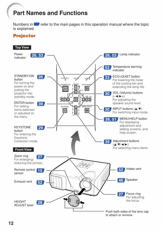
Numbers in Z refer to the main pages in this operation manual where the topicis explained.
Projector
Part Names and Functions
29
39
53
30
30
27
28
15
52
52
27
46
3326
26, 53
39, 51
26, 53
39
Top View
STANDBY/ONbuttonFor turning thepower on andputting theprojector intostandby mode.
Lamp indicator
Temperature warningindicator
Adjustment buttons(P/R/O/Q)For selecting menu items.
VOL (Volume) buttons(–O/Q+)For adjusting thespeaker sound level.ENTER button
For settingitems selectedor adjusted onthe menu.
MENU/HELP buttonFor displayingadjustment andsetting screens, andhelp screen.
Focus ringFor adjustingthe focus.
INPUT buttons (P/R)For switching input mode.
Remote controlsensor
HEIGHTADJUST lever
KEYSTONEbuttonFor entering theKeystoneCorrection mode.
Intake vent
Powerindicator
Zoom ringFor enlarging/reducing the picture.
Push both sides of the lens capto attach or remove.
ECO+QUIET buttonFor lowering the noiseof the cooling fan andextending the lamp life.
Front View
Exhaust ventSpeaker

13
Intro
du
ction
28
35
22
22
2122
23
25
23
23
24
25
2122
23
Numbers in Z refer to the main pages in this operation manual where the topicis explained.
Rear View
Using the Kensington Lock• This projector has a Kensington Security Standard connector for use with a Kensington
MicroSaver Security System. Refer to the information that came with the system forinstructions on how to use it to secure the projector.
Terminals
AUDIO 2 inputterminal
S-VIDEO input terminalTerminal for connectingvideo equipment with anS-video terminal.
VIDEO inputterminalTerminal forconnecting videoequipment.
Rear adjustmentfoot
Kensington SecurityStandard connector
AC socketConnect the suppliedpower cord.
AUDIO OUT terminal
Audio output terminal ofequipment connected to theaudio input terminal.
AUDIO 1 input terminal
DVI-I inputterminalTerminalfor DVI digital,computer RGB andcomponent signals.
LAN terminalTerminal forcontrolling the projectorusing a computer vianetwork.
RS-232C terminalTerminal forcontrolling theprojector using acomputer.
COMPUTER/COMPONENT inputterminalTerminal for computer RGBand component signals.
USB terminal
Terminal connectingwith the USBterminal on thecomputer for usingthe supplied remotecontrol as thecomputer mouse.
MONITOR OUT terminal(Output terminal for computerRGB, component and DVI analogsignals. Shared for COMPUTER/COMPONENT and DVI-I)Terminal for connecting amonitor.

14
30
33
34
3539
33
33
26
35
29
34
33
26
34
30
33
3539
3951
31
39
30
34
35
STANDBY button
For putting the projectorinto the standby mode.
BREAK TIMER buttonFor displaying thebreak time.
COMPUTER, DVI,
S-VIDEO, VIDEO buttonsFor switching to therespective input modes.
PAGE UP/PAGEDOWN buttonsSame as the [Page Down] and[Page Up] keys on a computerkeyboard, when with the USBconnection (using a USB cableor the optional remotereceiver).
POINTER buttonFor displaying thepointer.
MOUSE/Adjustmentbuttons (P/R/O/Q)• For moving the
computer cursor when with the USBconnection (using a USB cable or theoptional remote receiver).
• For selecting and adjusting menuitems.
L-CLICK/EFFECTbutton• For the Left click
when with the USB connection(using a USB cable or the optionalremote receiver).
• For changing the pointer or spotarea.
KEYSTONE buttonFor entering theKeystone Correction mode.
AUTO SYNC buttonFor automaticallyadjusting images whenconnected to a computer.
ECO+QUIET buttonFor lowering the noiseof the cooling fan andextending the lamp life.
AV MUTE buttonFor temporarilydisplaying a blackscreen and turningoff the sound.
FREEZE buttonFor freezing images.
VOL +/– (Volume)buttonsFor adjusting thespeaker sound level.
ON buttonFor turning the poweron.
SPOT buttonFor displaying thespotlight.
R-CLICK/RETURNbutton• For the Right click
when with the USBconnection (using aUSB cable or theoptional remotereceiver).
• For returning to theprevious menu screenduring menuoperations.
ENTER buttonFor setting itemsselected or adjustedon the menu.
MENU/HELP buttonFor displayingadjustment andsetting screens, andhelp screen.
PICTURE MODEbuttonFor selecting theappropriate picture.
RESIZE buttonFor switching thepicture size(NORMAL,STRETCH, etc.).
MAGNIFY buttonsFor enlarging/reducingpart of the image.
Part Names and Functions (Continued)

15
Intro
du
ction
Remote control sensor
Remote control signaltransmitters
Remote control
23n (7 m)
30°
30°
Inserting the Batteries
Insert the lower tab of the cover into the opening,and lower the cover until it clicks in place.
Insert the batteries.• Insert the batteries making sure the polarities correctly match
the m and n marks inside the battery compartment.
Pull down the tab on the cover and remove the covertowards the direction of the arrow.
1
• Danger of explosion if battery is incorrectly replaced.Replace only with alkaline or manganese batteries.
• Insert the batteries making sure the polarities correctly match the m and n marks inside the batterycompartment.
• Batteries of different types have different properties, therefore do not mix batteries of different types.• Do not mix new and old batteries.
This may shorten the life of new batteries or may cause old batteries to leak.• Remove the batteries from the remote control once they have run out, as leaving them in can cause them
to leak.Battery fluid from leaked batteries is harmful to skin, therefore ensure you wipe them first and then removethem using a cloth.
• The batteries included with this projector may run down in a short period, depending on how they are kept.Be sure to replace them as soon as possible with new batteries.
• Remove the batteries from the remote control if you will not be using the remote control for a long time.• Comply with the rules (ordinance) of each local government when disposing of worn-out batteries.
Incorrect use of the batteries may cause them to leak or explode. Pleasefollow the precautions below.
Caution
Usable RangeThe remote control can be used to control theprojector within the ranges shown in theillustration.
Note
• The signal from the remote control can be re-flected off a screen for easy operation. How-ever, the effective distance of the signal maydiffer depending on the screen material.
When using the remote control• Ensure that you do not drop it or expose it to
moisture or high temperature.• The remote control may malfunction under a
fluorescent lamp. In this case, move the pro-jector away from the fluorescent lamp.
2
3

16
Quick Start
This section shows the basic operation (projector connecting with the computer). For details, seethe page described below for each step.
Setup and ProjectionIn this section, connection of the projector and the computer is explained using one example.
When connecting equipment other than a computer, seepages 22 and 23.
3. Remove the lens cap and turn the projector on
2. Connect the projector to the computer and plug the power cordinto the AC socket of the projector
On the projector On the remote control
KEYSTONE button
INPUT buttons
STANDBY/ONbutton
HEIGHTADJUST lever
Focus ring
STANDBY button
_PP. 21, 24, 25
_P. 26
ENTER button
ENTER button
6
4
3
5
8
3
5
6
8
KEYSTONEbutton
4
4
ON button
COMPUTER button
4
1. Place the projector facing a wall or a screen _P. 18
5 Adjustment buttons(P/R/O/Q)
5 Adjustment buttons(P/R/O/Q)
Zoom ring4
17
Qu
ick Start
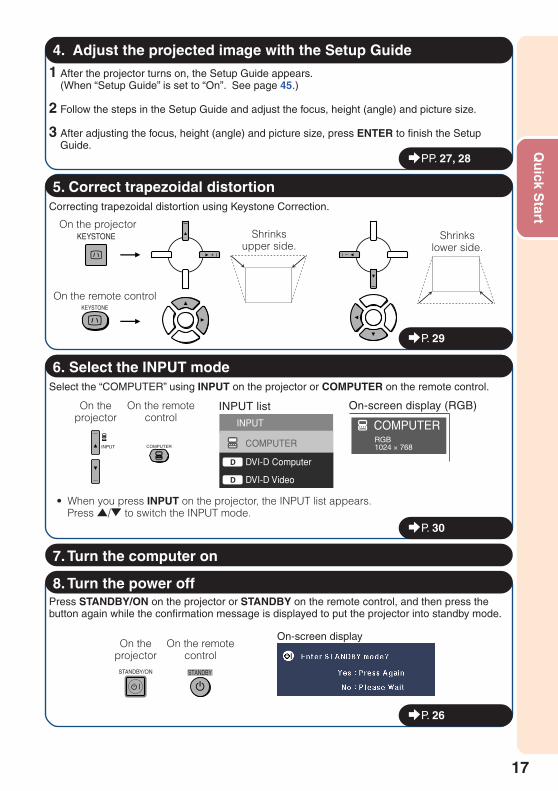
4. Adjust the projected image with the Setup Guide
_PP. 27, 28
1 After the projector turns on, the Setup Guide appears.(When “Setup Guide” is set to “On”. See page 45.)
2 Follow the steps in the Setup Guide and adjust the focus, height (angle) and picture size.
3 After adjusting the focus, height (angle) and picture size, press ENTER to finish the SetupGuide.
Correcting trapezoidal distortion using Keystone Correction.
5. Correct trapezoidal distortion
8. Turn the power offPress STANDBY/ON on the projector or STANDBY on the remote control, and then press thebutton again while the confirmation message is displayed to put the projector into standby mode.
On-screen displayOn the
projectorOn the remote
control
_P. 26
On the projector
On the remote control
Shrinksupper side.
Shrinkslower side.
_P. 29
Select the “COMPUTER” using INPUT on the projector or COMPUTER on the remote control.
6. Select the INPUT mode
• When you press INPUT on the projector, the INPUT list appears.Press '/" to switch the INPUT mode.
On theprojector
On the remotecontrol
INPUT list
_P. 30
INPUT
COMPUTER
DVI-D ComputerD
DVI-D VideoD
On-screen display (RGB)
RGB1024 × 768
COMPUTER
7. Turn the computer on
18
Ceiling-mount Setup
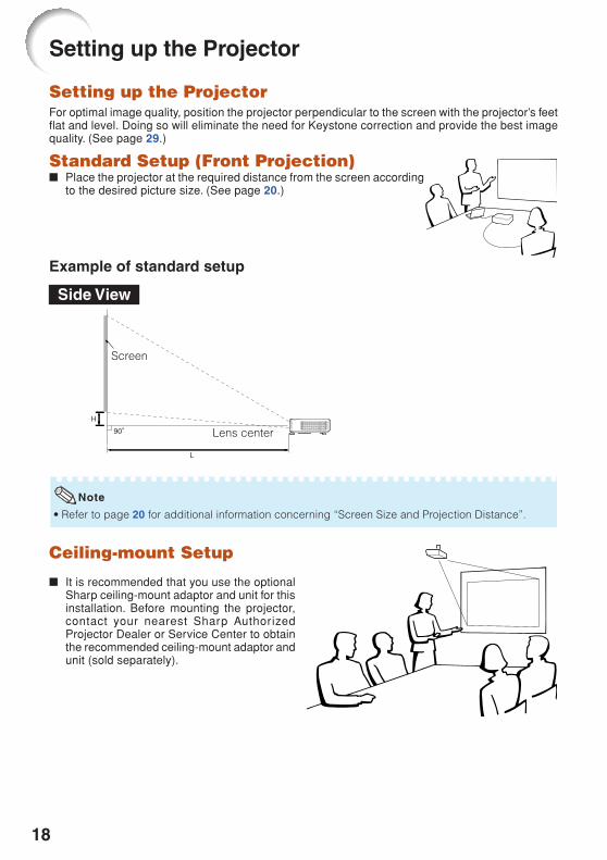
■ It is recommended that you use the optionalSharp ceiling-mount adaptor and unit for thisinstallation. Before mounting the projector,contact your nearest Sharp AuthorizedProjector Dealer or Service Center to obtainthe recommended ceiling-mount adaptor andunit (sold separately).
Setting up the Projector
Setting up the ProjectorFor optimal image quality, position the projector perpendicular to the screen with the projector’s feetflat and level. Doing so will eliminate the need for Keystone correction and provide the best imagequality. (See page 29.)
Standard Setup (Front Projection)■ Place the projector at the required distance from the screen according
to the desired picture size. (See page 20.)
Example of standard setup
Screen
Lens centerH
L
• Refer to page 20 for additional information concerning “Screen Size and Projection Distance”.
Note
Side View

19
Setu
p
300"
200"
100"
60"
254"�159"
170"�106"85"�53"
51"�32"
30'5"– 35'0"
(9.3 m – 10.7 m)20'3"– 23'4"
(6.2 m – 7.1 m)10'2"– 11'8"
(3.1 m – 3.6 m)6'1"– 7'0"
(1.9 m – 2.1 m)
Projection (PRJ) ModeThe projector can use any of the 4 projection modes shown in the diagram below. Select the modemost appropriate for the projection setting in use. (You can set the PRJ mode in “SCR-ADJ” menu.See page 45.)
■ Table mounted, front projection[Menu item ➞ “Front”]
■ Ceiling mounted, front projection[Menu item ➞ “Ceiling + Front”]
■ Table mounted, rear projection(with a translucent screen)[Menu item ➞ “Rear”]
■ Ceiling mounted, rear projection(with a translucent screen)[Menu item ➞ “Ceiling + Rear”]
Indication of the Projection Image Size and Projection Distance
Picture Size
ProjectionDistance
Example: 16:10 Signal Input (Normal Mode)
20
Setting up the Projector (Continued)
300" (762 cm)
250" (635 cm)
200" (508 cm)
150" (381 cm)
120" (305 cm)
100" (254 cm)
80" (203 cm)
60" (152 cm)
40" (102 cm)
646 cm (254")
538 cm (212")
431 cm (170")
323 cm (127")
258 cm (102")
215 cm (85")
172 cm (68")
129 cm (51")
86 cm (34")
404 cm (159")
337 cm (132")
269 cm (106")
202 cm (79")
162 cm (64")
135 cm (53")
108 cm (42")
81 cm (32")
54 cm (21")
9.3 m
7.7 m
6.2 m
4.6 m
3.7 m
3.1 m
2.5 m
1.9 m
1.2 m
(30' 5")
(25' 4")
(20' 3")
(15' 2")
(12' 2")
(10' 2")
(8' 1")
(6' 1")
(4' 1")
(35' 0")
(29' 2")
(23' 4")
(17' 6")
(14' 0")
(11' 8")
(9' 4")
(7' 0")
(4' 8")
10.7 m
8.9 m
7.1 m
5.3 m
4.3 m
3.6 m
2.8 m
2.1 m
1.4 m
7 cm
6 cm
5 cm
4 cm
3 cm
2 cm
2 cm
1 cm
1 cm
(2 53/64")
(2 23/64")
(1 57/64")
(1 27/64")
(1 9/64")
(15/16")
(3/4")
(9/16")
(3/8")
The formula for picture size and projection distance[m/cm]L1 (m) = 0.03498χL2 (m) = 0.0403χH (cm) = 0.02717χ
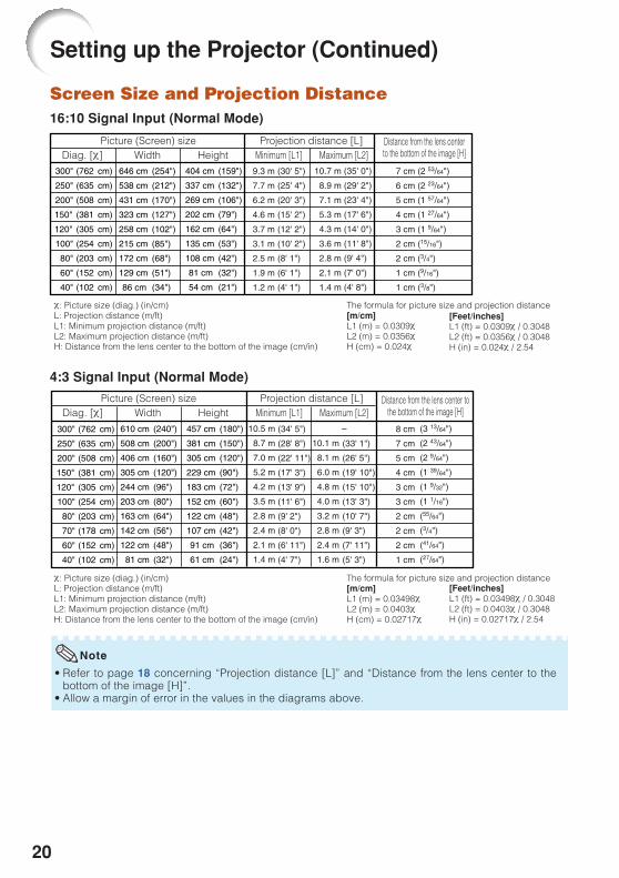
Screen Size and Projection Distance16:10 Signal Input (Normal Mode)
• Refer to page 18 concerning “Projection distance [L]” and “Distance from the lens center to thebottom of the image [H]”.
• Allow a margin of error in the values in the diagrams above.
Picture (Screen) size
The formula for picture size and projection distance[m/cm]L1 (m) = 0.0309χL2 (m) = 0.0356χH (cm) = 0.024χ
χ: Picture size (diag.) (in/cm)L: Projection distance (m/ft)L1: Minimum projection distance (m/ft)L2: Maximum projection distance (m/ft)H: Distance from the lens center to the bottom of the image (cm/in)
χ: Picture size (diag.) (in/cm)L: Projection distance (m/ft)L1: Minimum projection distance (m/ft)L2: Maximum projection distance (m/ft)H: Distance from the lens center to the bottom of the image (cm/in)
Projection distance [L]Diag. [χ] Width Height Minimum [L1] Maximum [L2]
457 cm (180")
381 cm (150")
305 cm (120")
229 cm (90")
183 cm (72")
152 cm (60")
122 cm (48")
107 cm (42")
91 cm (36")
61 cm (24")
300" (762 cm)
250" (635 cm)
200" (508 cm)
150" (381 cm)
120" (305 cm)
100" (254 cm)
80" (203 cm)
70" (178 cm)
60" (152 cm)
40" (102 cm)
610 cm (240")
508 cm (200")
406 cm (160")
305 cm (120")
244 cm (96")
203 cm (80")
163 cm (64")
142 cm (56")
122 cm (48")
81 cm (32")
10.5 m
8.7 m
7.0 m
5.2 m
4.2 m
3.5 m
2.8 m
2.4 m
2.1 m
1.4 m
(34' 5")
(28' 8")
(22' 11")
(17' 3")
(13' 9")
(11' 6")
(9' 2")
(8' 0")
(6' 11")
(4' 7")
10.1 m
8.1 m
6.0 m
4.8 m
4.0 m
3.2 m
2.8 m
2.4 m
1.6 m
(33' 1")
(26' 5")
(19' 10")
(15' 10")
(13' 3")
(10' 7")
(9' 3")
(7' 11")
(5' 3")
8 cm
7 cm
5 cm
4 cm
3 cm
3 cm
2 cm
2 cm
2 cm
1 cm
(3 13/64")
(2 43/64")
(2 9/64")
(1 39/64")
(1 9/32")
(1 1/16")
(55/64")
(3/4")
(41/64")
(27/64")
–
Note
Distance from the lens centerto the bottom of the image [H]
Picture (Screen) size Projection distance [L]Diag. [χ] Width Height Minimum [L1] Maximum [L2]
Distance from the lens center tothe bottom of the image [H]
[Feet/inches]L1 (ft) = 0.0309χ / 0.3048L2 (ft) = 0.0356χ / 0.3048H (in) = 0.024χ / 2.54
[Feet/inches]L1 (ft) = 0.03498χ / 0.3048L2 (ft) = 0.0403χ / 0.3048H (in) = 0.02717χ / 2.54
4:3 Signal Input (Normal Mode)
21
Co
nn
ection
s
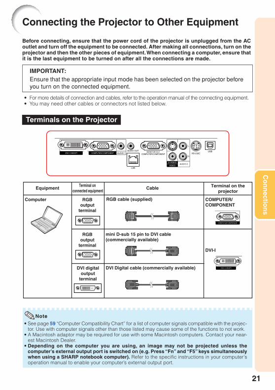
Before connecting, ensure that the power cord of the projector is unplugged from the ACoutlet and turn off the equipment to be connected. After making all connections, turn on theprojector and then the other pieces of equipment. When connecting a computer, ensure thatit is the last equipment to be turned on after all the connections are made.
IMPORTANT:Ensure that the appropriate input mode has been selected on the projector beforeyou turn on the connected equipment.
• For more details of connection and cables, refer to the operation manual of the connecting equipment.• You may need other cables or connectors not listed below.
Connecting the Projector to Other Equipment
COMPUTER/COMPONENT
DVI-I
Equipment
Computer
DVI digitaloutput
terminal
Cable
DVI Digital cable (commercially available)
mini D-sub 15 pin to DVI cable (commercially available)
Terminal on connected equipment
Terminal on theprojector
RGBoutput
terminal
RGBoutput
terminal
RGB cable (supplied)
• See page 59 “Computer Compatibility Chart” for a list of computer signals compatible with the projec-tor. Use with computer signals other than those listed may cause some of the functions to not work.
• A Macintosh adaptor may be required for use with some Macintosh computers. Contact your near-est Macintosh Dealer.
• Depending on the computer you are using, an image may not be projected unless thecomputer’s external output port is switched on (e.g. Press “Fn” and “F5” keys simultaneouslywhen using a SHARP notebook computer). Refer to the specific instructions in your computer'soperation manual to enable your computer’s external output port.
Note
Terminals on the Projector

22
Connecting the Projector to Other Equipment (Continued)
S-VIDEO
VIDEO
COMPUTER/COMPONENT
Equipment
Video equipment
Camera/Video game
Cable
S-video cable (commercially available)
Video cable (commercially available)
Cables for a camera or a video game
Cables for a camera or a video game
Cables for a camera or a video game/3 RCAto mini D-sub 15 pin cable (optional,AN-C3CP2)
Terminal on connected equipment
Terminal on theprojector
S-videooutput
terminal
Videooutput
terminal
S-videooutput
terminal
Videooutput
terminal
Componentvideooutput
terminalRCA adaptor plug(commercially available)
S-VIDEO
VIDEO
3 RCA to mini D-sub 15 pin cable (optional, AN-C3CP2)
COMPUTER/COMPONENT
Componentvideooutput
terminal
HDMI to DVI cable (commercially available)
DVI-I
HDMIoutput
terminal
DVI digitaloutput
terminal
DVI Digital cable (commercially available)
• While the projector is connected to video equipment that has an HDMI output terminal, only thevideo signal can be input to the projector. (Connect the AUDIO input terminal for audio input.)
• Depending on specifications of video equipment or HDMI to DVI digital cable, the signal transmissionmay not work property. (The HDMI specification does not support all connections to video equipmentthat has HDMI digital output terminal using HDMI to DVI digital cable.)
• For details on compatibility for connection, see support information on DVI connection provided bythe video equipment manufacturer.
• When you connect video equipment with a 21-pin RGB output (Euro-scart) to the projector, use acommercially available cable that fits in the projector terminal you want to connect.
• The projector does not support RGBC signals via the Euro-scart.
Note
23
Co
nn
ection
s
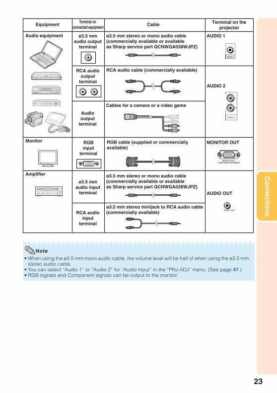
Note• When using the ø3.5 mm mono audio cable, the volume level will be half of when using the ø3.5 mm
stereo audio cable.• You can select “Audio 1” or “Audio 2” for “Audio Input” in the “PRJ-ADJ” menu. (See page 47.)• RGB signals and Component signals can be output to the monitor.
Equipment CableTerminal on
connected equipmentTerminal on the
projector
Audiooutput
terminal
Monitor
Amplifier
MONITOR OUT
AUDIO OUT
RGBinput
terminal
RGB cable (supplied or commercially available)
Audio equipment ø3.5 mm stereo or mono audio cable(commercially available or available as Sharp service part QCNWGA038WJPZ)
ø3.5 mmaudio output
terminal
ø3.5 mmaudio input
terminal
RCA audiooutput
terminal
RCA audioinput
terminal
ø3.5 mm stereo or mono audio cable(commercially available or available as Sharp service part QCNWGA038WJPZ)
ø3.5 mm stereo minijack to RCA audio cable(commercially available)
RCA audio cable (commercially available)
Cables for a camera or a video game
AUDIO 2
AUDIO 1

24
Controlling the Projector by a Computer
When the RS-232C terminal on the projector is connected to a computer with a DIN-D-sub RS-232C adaptor and an RS-232C serial control cable (cross type, commercially available), the computercan be used to control the projector and check the status of the projector. Refer to the “SETUPMANUAL” contained on the supplied CD-ROM for “RS-232C Specifications and Commands”.
When connecting to a computer using an RS-232C serial control cable and a DIN-D-sub RS-232C adaptor
To RS-232C terminal
DIN-D-sub RS-232Cadaptor (supplied)
RS-232C serial control cable (cross type, commercially available)
Note• The RS-232C function may not operate if your computer terminal is not correctly set up. Refer to the
operation manual of the computer for details.• Refer to pages 2 to 8 of the “SETUP MANUAL” contained on the supplied CD-ROM for “Connecting
Pin Assignments” and “RS-232C Specifications and Commands”.
Info• Do not connect the RS-232C cable to a port other than the RS-232C terminal on the computer. This
may damage your computer or projector.• Do not connect or disconnect an RS-232C serial control cable to or from the computer while it is on.
This may damage your computer.
Computer
To RS-232C terminal

25
Co
nn
ection
s
Connecting the Power Cord
Plug the supplied power cord into theAC socket on the rear of the projector.Then plug into AC outlet.
AC socket
To AC outletPower cord(supplied)
When connecting to the LAN terminal using a LAN cable
TX/RX LED (yellow)Illuminates when transmitting/receiving data.
LINK LED (green)Illuminates when linked.
* To ensure safety, do not connect the LAN terminal with anycables that may cause excessive voltage such as atelephone line.
Hubor
Computer
LAN cable (Category 5 type,commercially available)
To LAN terminal
Note• When connecting to a hub, use a straight-through Category 5 (CAT.5) type cable (commercially
available).• When connecting to a computer, use a cross-over Category 5 (CAT.5) type cable (commercially
available).

26
Turning the Projector On/Off
On-screen display (confirmation message)
• When “Auto Restart” is set to “On”:If the power cord is unplugged from the outletor the breaker switch is turned off when theprojector is on, then the projector automaticallyturns on when the power cord is plugged intothe AC outlet or the breaker switch is turnedon. (See page 46.)
• English is the factory default language. If youwant to change the on-screen display to an-other language, change the language accord-ing to the procedure on page 45.
Info
Turning the Projector on
Note that the connections to external equip-ment and power outlet should be done be-fore performing the operations written be-low. (See pages 21 to 25.)
Remove the lens cap and pressSTANDBY/ON on the projector or ONon the remote control.• The power indicator illuminates green.• After the lamp indicator illuminates, the projec-
tor is ready to start operation.
Note
• About the Lamp IndicatorThe lamp indicator illuminates to indicate thestatus of the lamp.
Green: The lamp is on.Blinking in green: The lamp is warming up.Red: The lamp is shut down abnormally
or the lamp should be replaced.• When switching on the projector, a slight flicker-
ing of the image may be experienced within thefirst minute after the lamp has been illuminated.This is normal operation as the lamp’s controlcircuitry is stabilising the lamp output character-istics. It should not be regarded as faultyoperation.
• If the projector is put into standby mode andimmediately turned on again, the lamp may takesome time to start projection.
• When System Lock is set, the keycode input boxappears. To cancel the keycode setting, input thekeycode that you have already set. See page 47for details.
Turning the Power off (Puttingthe Projector into Standby Mode)
Press STANDBY/ON on the projector orSTANDBY on the remote control, thenpress that button again while the confir-mation message is displayed, to put theprojector into standby mode.• The projector cannot be turned on while cool-
ing.
STANDBYbutton
ON button
• Direct Power Off function:You can unplug the power cord from the AC out-let even if the cooling fan is still running.
Info
STANDBY/ON button
Lamp indicator
Power indicator

27
Basic
Op
eration
About the Setup Guide
After turning on the projector, the SetupGuide screen appears to assist you withprojector setup.Guidance items1 FOCUS2 HEIGHT ADJUST3 ZOOM
Press ENTER to exit the Setup Guidescreen.
Image Projection
Setup Guide screen
• The Setup Guide screen automatically high-lights the items in the following order:
1 FOCUS
3 ZOOM4 ENTER
2 HEIGHT ADJUST
However, you can adjust the focus, height(angle), or zoom regardless of the highlighteditem.
• If you do not want to display the Setup Guidefor the next time, set “Menu” - “SCR - ADJ” -“Setup Guide” to “Off”. (See page 45.)
Note
Adjusting the Projected Image
1 Adjusting the FocusYou can adjust the focus with the focusring on the projector.
Rotate the focus ring to adjust the fo-cus while watching the projected image.
2 Adjusting the Picture SizeYou can adjust the picture size usingthe zoom ring on the projector.
Rotate the zoom ring to enlarge orshrink the picture size.
STANDBY/ONbutton
ENTER button
Focus ring
Zoom ring

28
Image Projection (Continued)
3 Adjusting the HeightThe height of the projector can be ad-justed using the adjustment feet at thefront and rear of the projector.When the screen is above the projec-tor, the projection image can be madehigher by adjusting the projector.
1
2
3
• Do not apply too much pressure on the pro-jector when the front adjustment foot comesout.
• When lowering the projector, be careful not toget your fingers caught in the area betweenthe adjustment foot and the projector.
• Hold the projector firmly while lifting or carrying.• Do not hold by the lens area.
Use the rear adjustment foot tomake the projector level.• The projector is adjustable ±2 degrees
from the standard position.
Remove your hands from theHEIGHT ADJUST lever of the pro-jector after its height has beenfinely adjusted.• The angle of projection is adjustable up
to 9 degrees from the surface on whichthe projector is placed.
Lift the projector to adjust itsheight while lifting the HEIGHTADJUST lever.
Info
• When adjusting the height of the projector,trapezoidal distortion occurs. Follow the pro-cedures in Keystone Correction to correct thedistortion. (See pages 29 and 44.)
Note
Rear adjustment foot
HEIGHTADJUST lever
Make smalladjustments.

29
Basic
Op
eration
0KEYSTONEADJUST END
Correcting TrapezoidalDistortion
When the image is projected either fromthe top or from the bottom towards thescreen at an angle, the image becomesdistorted trapezoidally. The function forcorrecting trapezoidal distortion iscalled Keystone Correction.
• The Keystone Correction can be adjusted upto an angle of approximately ±40 degrees andthe screen can also be set up to an angle ofapproximately ±40 degrees (when the resizemode is set to “NORMAL” (see page 31)).
Note
1
2
3 Press KEYSTONE.• The on-screen display of the Keystone
Correction mode will disappear.• You can also use KEYSTONE on the pro-
jector.
Press P/Q or O/R to adjust theKeystone Correction.• You can also adjust the Keystone Cor-
rection using the adjustment buttons onthe projector.
Press KEYSTONE to enter theKeystone Correction mode.• You can also display the on-screen dis-
play of the Keystone Correction modewith KEYSTONE on the projector.
• To return to the default setting, press RETURNwhile the on-screen display of the KeystoneCorrection mode is on the screen.
Note
On-screen display(Keystone Correction mode)
Shrinks upper side.(Move the slide bar in the + direction.)
Shrinks lower side.(Move the slide bar in the - direction.)
• While adjusting the image using KeystoneCorrection, straight lines and the edges of theimage may appear jagged.
Info
KEYSTONE button
Adjustment buttons(P/R/O/Q)
RETURN button

30
Image Projection (Continued)
Displaying the Black Screenand Turning off the SoundTemporarily
Adjusting the Volume
Switching the Input Mode
Press COMPUTER, DVI, S-VIDEO orVIDEO on the remote control to selectthe input mode.• When you press INPUT on the projector or DVI
on the remote control, the INPUT list appears.Press P/R to switch the INPUT mode.
Select the appropriate input mode forthe connected equipment.
Press VOL +/– on the remote control or–O/Q+ on the projector to adjust the vol-ume.
• Pressing VOL–/–O will lower the volume.• Pressing VOL+/Q+ will raise the volume.• When the projector is connected to external
equipment, the volume level of the external equip-ment changes in accordance with the volumelevel of the projector. Set the projector’s volumeto the lowest level when turning the projector on/off or when changing the input signal.
• When you do not want to output the sound fromthe projector’s speaker while the projector is con-nected to external equipment, set “Speaker” in“PRJ-ADJ” menu to “Off”. (See page 46.)
Press AV MUTE on the remote controlto temporarily display a black screenand turn off the sound.
• Pressing AV MUTE again will turn the pro-jected image back on.
On-screen display
Note
Note
On-screen display
VOL +/– (Volume)buttons
COMPUTER, DVI,S-VIDEO, VIDEObuttons
AV MUTE button

31
Basic
Op
eration
Resize Mode
This function allows you to modify or customize the resize mode to enhance the input image. De-pending on the input signal, you can choose a desired image.
Press RESIZE.• See page 44 for setting on menu screen.
RESIZEbutton
COMPUTER
STRETCH
Output screen imageInput signal
Image Type NORMAL FULL
4:3 aspect ratio
5:4 aspect ratio
15:9 aspect ratio
16:9 aspect ratio
16:10 aspect ratio
16:9 aspect ratio
Computer
ResolutionXGA and below
Resolutionhigher than
XGA
SXGA(1280 � 1024)
1280 � 720
1280 � 800
1360 � 7681366 � 768
1280 � 768
DOT BY DOT
*1*1
*1
*3
*1
*1
*2—
*2—
*2—
*2—
*1
*1
: Cutout area on which images cannot be projected: Area where the signals are off screen
*1 The Image Shift function can be used for these images.*2 Same as NORMAL mode.*3 In case SXGA+ input.
4:3 aspect ratio
Other aspect ratios
SVGA (800 × 600)
XGA (1024 × 768)
SXGA (1152 × 864)
SXGA+ (1400 × 1050)
SXGA (1280 × 1024)
1280 × 720
1360 × 768
1366 × 768
1280 × 768
1280 × 800
1068 × 800
1000 × 800
1280 × 720
1280 × 722
1280 × 720
1280 × 768
1280 × 800
1280 × 800
—
800 × 600
1024 × 768
1152 × 864
1400 × 1050
1280 × 1024
—
1360 × 768
1366 × 768
—
1280 × 720
—
1280 × 720
NORMAL FULL STRETCHDOT BY DOT

32
VIDEOVIDEO/DTV
About Copyrights• When using the RESIZE function to select an image size with a different aspect ratio to
a TV program or video image, the image will look different from its original appearance.Keep this in mind while choosing an image size.
• The use of the Resize or Keystone Correction function to compress or stretch the imagefor commercial purposes/public displays in a café, hotel, etc. may be an infringement ofcopyright protected by law for copyright holders. Please use caution.
Image Projection (Continued)
4:3 aspect ratio
Letter box
Squeeze
16:9 aspect ratio
16:9 aspect ratio
16:9 aspect ratio(4:3 aspect ratio in 16:9)
Output screen imageInput signal
Image Type NORMALVideo/DTV
480I, 480P,576I, 576P,NTSC, PAL,
SECAM
720P, 1035I,1080I, 1080P
540P
STRETCHAREA ZOOM V-STRETCH
16:9 aspect ratio
: Cutout area on which images cannot be projected: Area on which the image is not included in the original signals
*1 The Image Shift function can be used for these images.*2 Same as NORMAL mode.
*1
*1
*2—
*1
*1
*1
*1
*1
33
Usefu
lF
eatures
Operating with the Remote Control
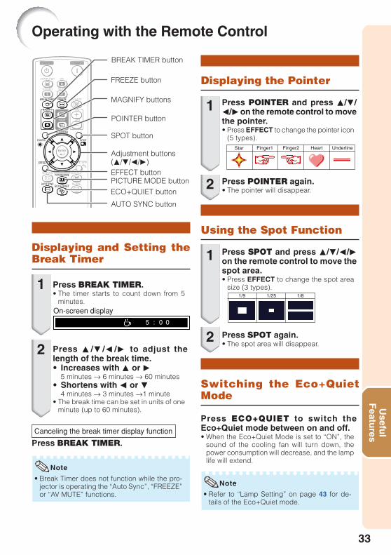
Displaying and Setting theBreak Timer
Press BREAK TIMER.• The timer starts to count down from 5
minutes.
1
2 Press P /R /O /Q to adjust thelength of the break time.• Increases with P or Q
5 minutes s 6 minutes s 60 minutes• Shortens with O or R
4 minutes s 3 minutes s1 minute• The break time can be set in units of one
minute (up to 60 minutes).
On-screen display
Canceling the break timer display function
Press BREAK TIMER.
• Break Timer does not function while the pro-jector is operating the “Auto Sync”, “FREEZE”or “AV MUTE” functions.
Note
Switching the Eco+QuietMode
Press ECO+QUIET to switch theEco+Quiet mode between on and off.• When the Eco+Quiet Mode is set to “ON”, the
sound of the cooling fan will turn down, thepower consumption will decrease, and the lamplife will extend.
Press POINTER and press P/R/O/Qon the remote control to movethe pointer.• Press EFFECT to change the pointer icon
(5 types).
Displaying the Pointer
Press SPOT and press P/R/O/Qon the remote control to move thespot area.• Press EFFECT to change the spot area
size (3 types).
Using the Spot Function
1
Press POINTER again.• The pointer will disappear.2
1
Press SPOT again.• The spot area will disappear.
2
• Refer to “Lamp Setting” on page 43 for de-tails of the Eco+Quiet mode.
Note
POINTER button
ECO+QUIET button
Adjustment buttons(P/R/O/Q)
BREAK TIMER button
SPOT button
AUTO SYNC button
FREEZE button
PICTURE MODE button
MAGNIFY buttons
EFFECT button
Star Finger1 Finger2 Heart Underline
1/9 1/25 1/8
34
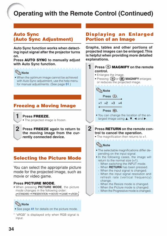
Auto Sync(Auto Sync Adjustment)
Freezing a Moving Image
• When the optimum image cannot be achievedwith Auto Sync adjustment, use the help menufor manual adjustments. (See page 51.)
Auto Sync function works when detect-ing input signal after the projector turnson.Press AUTO SYNC to manually adjustwith Auto Sync function.
Press FREEZE.• The projected image is frozen.
Press FREEZE again to return tothe moving image from the cur-rently connected device.
Note
Selecting the Picture Mode
Press PICTURE MODE.• When pressing PICTURE MODE, the picture
mode changes in the following order:STANDARD PRESENTATION MOVIE GAME sRGB
You can select the appropriate picturemode for the projected image, such asmovie or video game.
• See page 41 for details on the picture mode.
Note
*
* “sRGB” is displayed only when RGB signal isinput.
Displaying an EnlargedPortion of an Image
Graphs, tables and other portions ofprojected images can be enlarged. Thisis helpful when providing more detailedexplanations.
1
2
1
2
Press MAGNIFY on the remotecontrol.• Enlarges the image.• Pressing or MAGNIFY enlarges
or reduces the projected image.
Note
�1 �2 �3 �4
Press .
Press .• You can change the location of the en-
larged image using P, R, O and Q.
Press RETURN on the remote con-trol to cancel the operation.• The magnification then returns to ×1.
Note
• The selectable magnifications differ de-pending on the input signal.
• In the following cases, the image willreturn to the normal size (×1).- When switching the INPUT mode.- When RETURN has been pressed.- When the input signal is changed.- When the input signal resolution and
refresh rate (vertical frequency)change.
- When the Resize mode is changed.- When the Picture mode is changed.- When the Progressive mode is changed.
Operating with the Remote Control (Continued)

35
Usefu
lF
eatures
Using the Remote Control as the Wireless Computer MouseWhen connecting the projector and the computer with a USB cable, you can usethe remote control as the computer mouse.If the computer is placed too far away from the projector to be connected via theUSB cable, the remote receiver (optional, AN-MR2) makes it possible to operatethe projector with the remote control. For details, see the operation manual ofthe receiver.
Connecting with a USB cable
or
Remote receiver (optional, AN-MR2)To USB terminal
USB cable(commercially available or available as Sharp service part QCNWGA014WJPZ)
To USB terminal
Computer
MOUSE/Adjustmentbuttons ('/"/\/|)
R-CLICK button
L-CLICK button
PAGE UP/PAGE DOWN buttonsThe mouse pointer can be oper-
ated in the following way after itis connected.
■ When moving the cursorPress MOUSE/Adjustment buttons (P/R/O/Q).
■ When left-clicking Press L-CLICK.
■ When right-clicking Press R-CLICK.
■ When your computer supports only aone-click mouse (such as Macintosh)Press L-CLICK or R-CLICK.L-CLICK and R-CLICK have common function.
■ When using [Page Up] or [Page Down]
• This function only works with the Microsoft® Windows® OS and Mac OS®. However, this functiondoes not work with the following operation systems that do not support USB.
• Versions earlier than Windows® 95• Versions earlier than Windows® NT4.0• Versions earlier than Mac OS® 8.5
• You cannot use this function when displaying the menu screen.• Confirm that the computer recognizes the USB connection.
Note
Same as the [Page Up] and [Page Down] keys on a computer keyboard. Press PAGE UP or PAGE DOWN.

36
The following shows the items that can be set in the projector.
Menu Items
Picture ModeContrast 0
000
BrightColorTint
0Sharp
Standard
SEL./ADJ. ENTER END
00
RedBlue
Picture SCR PRJ Net. Help
Picture Mode
CLR TempBrilliantColorTM
C.M.S. SettingC.M.S.
Standard
SEL./ADJ. ENTER END
Progressive
Lamp Setting
01
On
3D Progressive
Bright
DNR Off
Reset
Picture SCR PRJ Net. Help
PAGE 2
Main menu Sub menu
Picture
Page 41 Page 41
Page 42
Page 42
Page 42
Page 42
Page 42
Page 43
Page 43
+30-30Contrast
+30-30
+30-30
+30-30
1-1
20
+30-30
+30-30
+30-30Tint
Color
Sharp
Bright
Progressive
Lamp Setting
Reset
2D Progressive3D ProgressiveFilm Mode
CLR Temp
BrilliantColor™
C.M.S. Setting [On/Off]
C.M.S.
StandardPresentationMovieGamesRGB*1
Picture Mode
*2
*2
*2
Red
Blue
*2
Page 43DNR Off
Level 1Level 2
BrightEco + Quiet
C.M.S.-Hue
C.M.S.-Saturation
C.M.S.-Value
Page 42
Page 42
Page 42Reset
+30-30R
+30-30
+30-30
+30-30
+30-30
+30-30C
G
B
Y
M
Reset
*1 Items when inputting RGB signal through COM-PUTER or DVI.
*2 Items when inputting component signal throughCOMPUTER or DVI, or when selecting S-VIDEO orVIDEO.
PAGE 1
“Picture” menu
“C.M.S.”
SEL./ADJ.Return
ENTEREND
C. M. S. - Hue
0000
C. M. S. - SaturationC. M. S. - Value
00
RYGCBM
C. M. S.
Reset
Reset

37
Usefu
lF
eatures
SEL./ADJ. ENTER END
ResizeImage Shift 0
0Keystone
OSD Display
BackgroundSetup GuidePRJ ModeLanguage
FrontEnglish
OnLogo
On
Stretch
Pict. SCR-ADJ PRJ Net. HelpMain menu Sub menu
SCR - ADJ
Page 44
Language
Image Shift
Resize
Page 44
Page 44
Page 44
Page 44
Page 45
Page 45
Page 45
Page 45
Keystone
OSD Display [On/Off]
Background
Setup Guide [On/Off]
PRJ Mode
LogoBlueNone
FrontCeiling + FrontRearCeiling + Rear
+80-80
+40-40
NormalFullDot By DotArea ZoomV-StretchStretch
NormalArea ZoomV-StretchStretch
COMPUTER/DTV
VIDEO/S-VIDEO
EnglishDeutschEspañolNederlandsFrançaisItalianoSvenskaPortuguês
polskiMagyarTürkçe
“Screen adjustment (SCR-ADJ)” menu
SEL./ADJ. ENTER END
Auto Power Off
System Sound
System Lockh
On
OnAuto Restart OnSTANDBY Mode Standard
0 min0Lamp Timer(Life) 100%
Auto Sync On
Pict. SCR PRJ-ADJ Net. Help
Speaker OnAudio Input Audio 1
RS-232C 9600bpsFan Mode Normal
Disable
Main menu Sub menu
PRJ - ADJ
Page 46
STANDBY Mode
System Sound [On/Off]
Speaker [On/Off]
System Lock[Enable/Disable]
Lamp Timer(Life)
Page 46
Auto Restart [On/Off]
Page 46
Auto Power Off [On/Off]
Page 46
Page 46
Page 46
Page 47
Page 48
Fan Mode
Page 47NormalHigh
RS-232C
Page 479600bps115200bps
Audio Input
Page 47Audio 1Audio 2
StandardEco
Auto Sync [On/Off]
Page 46
“Projector adjustment (PRJ-ADJ)” menu

38
SEL ENTER END
There is no picture or audioVertical stripes or flickering image appearData image is not centeredColor is faded or poorPicture is darkThe image is distorted
Reset all adjustments to default settings
SEL.
Pict. SCR PRJ Net. Help The items you can set with the “Help”menu
“Help” menu n Page 51• Vertical stripes or flickering image appear
Auto SyncClockPhase
• Data image is not centeredAuto SyncH-PosV-Pos
• Color is faded or poorCOMPUTER/COMPONENT or DVI input
Signal type: Auto/RGB/ComponentS-VIDEO or VIDEO input
Video System: Auto/PAL/SECAM/NTSC3.58/NTSC4.43/PAL-M/PAL-N/PAL-60
DVI (Digital) inputDynamic range: Auto/Standard/Enhanced
* The selectable items vary depending on the in-put signal and the selected input mode.
“Help” menu
Main menu
Network
Page 49Password [Enable/Disable]
DHCP Client [On/Off]
TCP/IP
MAC Address
Projector
Page 49
Page 50
Page 50
Page 50
Page 50
“Network” menu
SEL./ADJ. ENTER END
Pict. SCR PRJ Network Help
Password Disable
DHCP Client Off
TCP/IP
MAC Address
Projector
XX : XX : XX : XX : XX : XX
XX-XXXX
Menu Items (Continued)

39
Usefu
lF
eatures
Menu Selections (Adjustments)
Example: Adjusting “Bright”.• This operation can also be performed by using the buttons on the projector.
Press MENU/HELP.• The “Picture” menu screen for the se-
lected input mode is displayed.
Example: “Picture” screen menu forCOMPUTER (RGB) input
Press Q or O and select “Picture”to adjust.
1
2Menu item
Picture ModeContrast 0
00
Bright
Standard
SEL./ADJ. ENTER END
00
RedBlueCLR TempBrilliantColorTM
C.M.S. SettingC.M.S.
Lamp Setting
01
On
Bright
DNR Off
Reset
Picture SCR PRJ Net. Help
Adjustment buttons (P/R/O/Q)
MENU/HELP button
ENTER button
Adjustment buttons(P/R/O/Q)
ENTER button
RETURN button• Press RETURN to return
to the previous screenwhen the menu isdisplayed.
MENU/HELP button
Using the Menu Screen

40
Press P or R and select “Bright”to adjust.• The selected item is highlighted.
• Press ENTER again to return to the pre-vious screen.
Press O or Q to adjust the itemselected.• The adjustment is stored.
Press MENU/HELP.• The menu screen will disappear.
3
4
5
0Bright
Picture
SEL./ADJ. Rtn. Menu END
Picture ModeContrast 0
0
Standard
SEL./ADJ. Single ADJ END
00
RedBlueCLR TempBrilliantColorTM
C.M.S. SettingC.M.S.
Lamp Setting
01
On
BrightReset
1 5Bright
DNR Off
Picture SCR PRJ Net. Help
Note
Picture Mode Standard
SEL./ADJ. Single ADJ END
ResizeImage Shift 0
0Keystone
Stretch
Picture ModeContrast 0
0
Standard
SEL./ADJ. END
00
RedBlueCLR TempBrilliantColorTM
C.M.S. SettingC.M.S.
Lamp Setting
01
On
BrightReset
Bright 0
DNR Off
Picture SCR PRJ Net. Help
Pict. SCR-ADJ PRJ Net. Help
Items to be adjusted
• Menu buttons do not function while the projector is operating the “Auto Sync”, “Break Timer”,“FREEZE”, or “AV MUTE” functions.
Note
To adjust the projectedimage while watching itPress ENTER.• The selected item (e.g. “Bright”) is dis-
played by itself at the bottom of thescreen.
• When pressing P or R, the following item(“Red” after “Bright”) will be displayed.
The item displayed by itself
Press ENTER.
Using the Menu Screen (Continued)

41
Usefu
lF
eatures
Picture Adjustment (“Picture” Menu)
Standard
Presentation
Movie
Game
*sRGB
Q PAGE1 Q PAGE2
Picture ModeContrast 0
000
BrightColorTint
0Sharp
Standard
SEL./ADJ. ENTER END
00
RedBlue
Picture SCR PRJ Net. Help
1
2
For standard image
Brightens portions of image formore enhanced presentations.
Gives natural tint to theprojected image.
Gives sharpness to theprojected image.
For high fidelity reproduction ofimages from a computer.
Picture Mode
CLR TempBrilliantColorTM
C.M.S. SettingC.M.S.
Standard
SEL./ADJ. ENTER END
Progressive
Lamp Setting
01
On
3D Progressive
Bright
DNR Off
Reset
Picture SCR PRJ Net. Help
765
4
23
Menu operation n Page 39
• You can also press PICTURE MODE on the remote control to select the picture mode. (See page 34.)• *sRGB is an international standard of color reproduction regulated by the IEC (International
Electrotechnical Commission). As the fixed color area has been decided by the IEC, the images aredisplayed in a natural tint based on an original image, when “sRGB” is selected.For additional information about the sRGB function, visit “http://www.srgb.com/”.You cannot set the items, “Red”, “Blue”, “CLR Temp”, “BrilliantColorTM”, when “sRGB” is selected.
Note
1 1 1 1 1 Selecting the Picture Mode
• When “sRGB” is selected, the projected image may become dark, but this does not indicate amalfunction.
Info
• “sRGB” is displayed only when RGB signal is input.• You can set or adjust each item in the “Picture” menu to your preference. Any changes you make are
retained in memory.
0
0
–1
0
–
Bright
Bright
Eco + Quiet
Bright
Bright
The default settings of each item when selecting Picture Mode
1
2
0
1
–
CLR Temp
Selectableitems
DescriptionBrilliantColorTM Lamp Setting

42
22222 Adjusting the Image
*1 Not displayed in the RGB input mode.*2 Not adjustable/selectable when selecting “sRGB”.*3 BrilliantColor™ uses Texas Instruments’
BrilliantColor™ technology. As the BrilliantColor™level is increased, the image becomes brighterwhile the color reproduction is kept at a high level.
Q button
For morecontrast.For morebrightness.For more colorintensity.For making skintones greenish.For moresharpness.For stronger red.For stronger blue.For making theeffect stronger.
Adjustmentitems
Contrast
Bright
Color*1
Tint*1
Sharp*1
Red*2
Blue*2
BrilliantColor™*2 *3
O button
For lesscontrast.For lessbrightness.For less colorintensity.For making skintones purplish.For lesssharpness.For weaker red.For weaker blue.For making theeffect weaker.
Note• “Red”, “Blue”, “BrilliantColorTM” and “CLR
Temp” cannot be set when “sRGB” is selected.• To reset all adjustment items, select “Reset”
and press ENTER.
33333 Adjusting the ColorTemperature
• Values on “CLR Temp” are only for generalstandard purposes.
Note
Selectableitems
–1
0
1
Description
For lower color temperature forwarmer, reddish incandescent-likeimages.
For higher color temperature forcooler, bluish, fluorescent-like images.
Menu operation n Page 39
P
R
44444 Adjusting the ColorsThis function adjusts each of the six main colorsthat comprise the color wheel, altering their“Hue”, “Saturation”, or “Value”.
Selectable items
C.M.S.-Hue
C.M.S.-Saturation
C.M.S.-Value
Reset
Description
Sets the hue of the main colors.
Sets the saturation of the maincolors
Sets the brightness of the maincolors.
The adjustments of “Hue”,“Saturation” and “Value” of allcolors are reset to the defaultsetting.
Adjusting “Hue”, “Saturation”, or “Value”.1Select “On” for “C.M.S. Setting” in the “Picture”
menu and then press ENTER.2Select “C.M.S.” in the “Picture” menu and then
press ENTER.3Press P or R to select either “Hue”, “Saturation”, or
“Value” and then press ENTER.4Select the color to be adjusted with P or R and
adjust it with O or Q.
Example of adjusting the “Hue”
• When “Saturation” is selected, the selectedcolor becomesO: lighter. Q: thicker.
• When “Value” is selected, the selected colorbecomesO: darker. Q: brighter.
• To reset the adjustment values of each colorto the default settings, select “Reset” and pressENTER.
Main colors
R (Red)
Y (Yellow)
G (Green)
C (Cyan)
B (Blue)
M (Magenta)
O button
Closer to magenta
Closer to red
Closer to yellow
Closer to green
Closer to cyan
Closer to blue
Q button
Closer to yellow
Closer to green
Closer to cyan
Closer to blue
Closer to magenta
Closer to red
Picture Adjustment (“Picture” Menu)(Continued)

43
Usefu
lF
eatures
55555 Progressive
• In NTSC or PAL60Hz, even if the 3D Progres-sive mode has been set, the three-two pulldown enhancement will be enabled automati-cally when the film source has been entered.
• When the image is blurred or noisy, switch tothe optimal mode.
* The film source is a digital video recording with theoriginal encoded as is at 24 frames/second. Theprojector can convert this film source to progres-sive video at 60 frames/second with NTSC andPAL60Hz or at 50 frames/second with PAL50Hzand SECAM to play back a high-definition image.
Selectableitems
2DProgressive
3DProgressive
Film Mode
Description
Useful to display fast-moving imagessuch as sports.
Useful to display relatively slow-moving images such as drama anddocumentary more clearly.
Reproduces the image of film source*clearly. Displays the optimized image offilm transformed with three-two pull down(NTSC and PAL60Hz) or two-two pulldown (PAL50Hz and SECAM) enhance-ment to progressive mode images.
Note 77777 Lamp Setting
• In the Eco + Quiet mode, the fan sound andpower consumption are lower than those inthe Bright mode. (Projection brightness de-creases as shown in the chart.)
Note
Selectableitems
Eco + Quiet
Bright
Brightness and Power consumption
Approx. 80%
100%
Menu operation n Page 39
66666 Reducing Image Noise (DNR)
Set “DNR” to “Off” in the following cases:• When the image is blurry.• When the contours and colors of moving
images drag.• When TV broadcasts with weak signals are
projected.
Note
Selectableitems
Off
Level 1
Level 2
Description
The DNR function is not activated.
Sets the DNR level for viewing aclearer picture.
Video digital noise reduction (DNR) provides highquality images with minimal dot crawl and crosscolor noise.
• This function is available for 480I and 576Isignals using COMPUTER/COMPONENT orDVI input.
• This function is available for all signals withS-VIDEO and VIDEO input.
Info

44
Adjusting the Projected Image(“SCR - ADJ” Menu)
SEL./ADJ. ENTER END
ResizeImage Shift 0
0Keystone
OSD Display
BackgroundSetup GuidePRJ ModeLanguage
FrontEnglish
OnLogo
On
Stretch
Pict. SCR-ADJ PRJ Net. Help
876
4
321
5
11111 Setting the Resize Mode
• For details of the Resize mode, see pages31 and 32.
• You can also press RESIZE on the remote con-trol to set the resize mode. (See page 31.)
Note
22222 Adjusting the ImagePosition
You can move the projected image vertically.
Q button
• This function only works in some RESIZEmodes. (See pages 31 and 32.)
Note
O button
Menu operation n Page 39
33333 Keystone Correction
When the image is projected either from the topor from the bottom towards the screen at an angle,the image becomes distorted trapezoidally. Thefunction for correcting trapezoidal distortion iscalled Keystone Correction.
Select “Keystone” on the “SCR-ADJ”menu and adjust with the slide bar.See page 29 for details of Keystone Correction.
• The Keystone Correction can be adjusted upto an angle of approximately ±40 degrees(when “Resize” is set to “Normal”).
• You can also press KEYSTONE on the remotecontrol or on the projector to adjust KeystoneCorrection.
Note
O buttonQ button
44444 Setting the On-screenDisplay
Selectableitems
On
Off
Description
All on-screen displays are displayed.
INPUT/VOLUME/AV MUTE/FREEZE/AUTO SYNC/RESIZE/PICTURE MODE/ECO+QUIET/MAGNIFY/ “An invalidbutton has been pressed.” are notdisplayed.

45
Usefu
lF
eatures
Menu operation n Page 39
The projector can switch the on-screen displaylanguage among 17 languages.
Selectable items
Front
Ceiling + Front
Rear
Ceiling + Rear
Description
Normal image (Projected fromthe front of the screen)
Inverted image (Projectedfrom the front of the screenwith an inverted projector)
Reversed image (Projectedfrom the rear of the screen orwith a mirror)
Reversed and inverted image(Projected with a mirror)
88888 Selecting the On-screenDisplay Language
77777 Reversing/InvertingProjected Images
EnglishDeutschEspañolNederlandsFrançaisItalianoSvenskaPortuguês
polskiMagyar
Türkçe
See page 19 for details of Projection (PRJ) Mode.
55555 Selecting the BackgroundImage
Selectable itemsLogoBlueNone
DescriptionSharp logo screenBlue screen—
66666 Selecting the Setup Guide
Selectable itemsOn
Off
DescriptionDisplaying the Setup Guidewhen turning the projector on.Not displaying the Setup Guide.

46
SEL./ADJ. ENTER END
Auto Power Off
System Sound
System Lockh
On
OnAuto Restart OnSTANDBY Mode Standard
0 min0Lamp Timer(Life) 100%
Speaker OnAudio Input Audio 1
RS-232C 9600bpsFan Mode Normal
Disable
Auto Sync On
Pict. SCR PRJ-ADJ Net. Help
1234567890
Menu operation n Page 39
• When the Auto Power Off function is set to“On”, 5 minutes before the projector entersstandby mode, the message “Enter STANDBYmode in X min.” will appear on the screen toindicate the remaining minutes.
Selectableitems
On
Off
Description
When no input signal is detected formore than 15 minutes, the projector willautomatically enter standby mode.
The Auto Power Off function will bedisabled.
Note
22222 Auto Power Off Function
66666 Speaker Setting
55555 Setting the ConfirmationSound (System Sound)
Selectableitems
On
Off
Description
A confirmation sound is made whenthe projector turns on/off.
No confirmation sound is made.
When set to “Eco”, power consumption isreduced in standby mode.
4 4 4 4 4 STANDBY Mode
Selectableitems
On
Off
Description
The audio signal is output from theinternal speaker.
The audio signal is not output from theinternal speaker.
Selectableitems
Eco
Standard
Description
The monitor output, RS-232C andNetwork functions are switched off instandby mode.
The monitor output, RS-232C andNetwork functions are activated even ifthe projector is in standby mode.
• Auto Sync adjustment is also performed bypressing AUTO SYNC on the remote control.
• The Auto Sync adjustment may take some timeto complete, depending on the image of thecomputer connected to the projector.
• When the optimum image cannot be achievedwith Auto Sync adjustment, use manualadjustments. (See page 51.)
Selectableitems
On
Off
Description
Auto Sync adjustment will occur whenthe projector is turned on or when theinput signals are switched, whenconnected to a computer.
Auto Sync adjustment is notautomatically performed.
Note
11111 Auto Sync (Auto SyncAdjustment)
33333 Auto Restart Function
Selectableitems
On
Off
Description
If the power cord is unplugged from theoutlet or the breaker switch is turned offwhen the projector is on, then theprojector automatically turns on whenthe power cord is plugged into the ACoutlet or the breaker switch is turned on.
The projector does not turn onautomatically when the power cord isplugged into the AC outlet or thebreaker switch is turned on.
Adjusting the Projector Function (“PRJ - ADJ” Menu)

47
Usefu
lF
eatures
Info• If you lose or forget your keycode, contact
your nearest Sharp Authorized ProjectorDealer or Service Center (see page 62). Evenif the product warranty is valid, the keycodereset will incur a charge.
0 0 0 0 0 System Lock FunctionThis function prevents unauthorized use of theprojector. Once this function is activated, usersmust enter the correct keycode each time theprojector is turned on. We suggest you recordthe keycode in a safe place where only au-thorized users have access.
9 9 9 9 9 Fan Mode SettingThis function changes the fan rotation speed.
Menu operation n Page 39
Selectableitems
Normal
High
Description
Suitable for normal environments.
Select this when using the projector ataltitudes of approximately 1,500meters (4,900 feet) or more.
88888 Selecting the TransmissionSpeed (RS-232C)
Make sure that both the projector and computerare set for the same baud rate.
Selectableitems
9600bps
115200bps
Description
Transmission speed is slow.
Transmission speed is rapid.
P
R
a Setting/Changing the keycode
When “Fan Mode” is set to “High”, the fan rotationspeeds up, and the fan noise becomes louder.
Select “System Lock”, then pressENTER or Q.
1
Select “Next”, then press ENTER.• The screen for entering the keycode
appears.
2
66666 Monitor OutputThis function allows you to select an appropriatecombination of audio input terminals for eachinput mode.
7 7 7 7 7 Audio Input
Selectableitems
Audio 1
Audio 2
Description
The AUDIO 1 input terminal is used asan audio input terminal.
The AUDIO 2 input terminal is used asan audio input terminal. Press the 4 buttons on the remote
control or on the projector to enterthe preset keycode in “Old Code”.• When setting the keycode for the first time,
press R on the projector for four times.
3
Setting the System Lock
PRJ - ADJ
Old CodeNew CodeReconfirm
– – – –– – – –– – – –
• If you input a wrong keycode, the cursorreturns to the first point of the “Old Code”.
• The preset keycode is 4 R buttons onthe projector. When you press the R but-ton four times, the keycord input screendisappears.
Note
• You cannot use the following buttons forkeycode: STANDBY/ON, ON, STANDBY,ENTER, L-CLICK, R-CLICK/RETURNand MENU/HELP
• System lock function recognizes eachbutton on the remote control or on theprojector as an individual button, even ifthey share the same button name. If youused the buttons on the projector insetting your keycode, the keycode cannotbe canceled with the remote control.
Press the 4 buttons on the remotecontrol or on the projector to enterthe new keycode in “New Code”.
Setting the System Lock
PRJ - ADJ
Old CodeNew CodeReconfirm
* * * *– – – –– – – –
4
Note

48
Note
Input screen for keycode
To cancel the keycode that you have alreadyset
• Press R on the projector for four times in steps4 and 5 above.
When the System Lock is set• When System Lock is set, the keycode input
screen appears after the power is turned on.When it appears, enter the right keycode tostart projection.
Enter the same keycode in “Re-confirm”.
System Lock – – – –
5Locking the OperationButtons on the ProjectorUse this function to lock the operation buttonson the projector.
a Taking the Keylock offHold down ENTER on the projector for about 5seconds.
On-screen display
a Locking the Operation ButtonsHold down ENTER on the projector for about 5seconds while the projector is being turned on.
On-screen display
• The keylock function does not affect the opera-tion with the remote control buttons.
• You cannot use the keylock function while theprojector is warming up.
• When the projector is in standby mode, you canrelease the keylock by holding down ENTERand STANDBY/ON on the projector simulta-neously for about 5 seconds.
Keylock Function
• Keylock cannot be set while the projector is:displaying the “Setup Guide” or “Menu”screens, in standby mode, warming up, chang-ing input signals, operating “Auto Sync”function, in “FREEZE” mode or on the “SystemLock” screen during warming up.
Info
Checking the Lamp LifeStatus
You can confirm the cumulative lamp usage timeand the remaining lamp life (percentage).
Lamp usage condition
Operated exclusivelywith Lamp Setting set to“Eco +Quiet”
Operated exclusivelywith Lamp Setting set to“Bright”
100%
Approx.4,000hours
Approx.2,000hours
5%
Approx.200 hours
Approx.100 hours
Remaining lamp life
“Life”
Note
• It is recommended that the lamp be changedwhen the remaining lamp life becomes 5%.
• The lamp life may vary depending on the us-age condition.
Adjusting the Projector Function (“PRJ - ADJ” Menu)(Continued)

49
Usefu
lF
eatures
Setting up the Projector Network Environment (“Network” menu)
If you do not want others to change the settingfor the “Network” menu, set a password.
Select “Password”, then pressENTER or Q.• The screen for entering the password
appears.
1
11111 Setting a Password
Press P or R to set the first digitin “New Password”, then press Q.
2
Enter the remaining 3 digits, thenpress ENTER.• To return to the previous digit, press O.
3
Enter the same password in “Re-confirm”, then press ENTER.• The status for “Password” changes to
“Enable”.
4
Note• Once after the password is set, you must en-
ter the password to change the “Network”menu settings.
Select “Password”, then pressENTER or Q.• The screen for entering the password
appears.
1
Enter the password in “Old Pass-word” using P, R, Q and O, thenpress ENTER.
Enter the password in “New Pass-word” using P, R, Q and O, thenpress ENTER.
Enter the same password again in“Reconfirm” using P, R, Q and O,then press ENTER.
Note• If you do not need the password protection
for the “Network” menu settings anymore,press ENTER without entering new passwordin steps 3 and 4.
• To cancel the password settings, pressRETURN.
If you forget the passwordIf you forget the password, perform the fol-lowing procedure to delete it, then set a newpassword.
On the projector, press.
Note• If ENTER is held down for more than 5 sec-
onds, the operation buttons on the projec-tor will be locked. (See page 48.)
• You cannot use the buttons on the remotecontrol to delete the password.
2
3
4
a Setting a Password
a Changing the Password
Menu operation n Page 39
SEL./ADJ. ENTER END
Pict. SCR PRJ Network Help
Password Disable
DHCP Client Off
TCP/IP
MAC Address
Projector
XX : XX : XX : XX : XX : XX
XX-XXXX4
2
3
1
Setting the Password
Old PasswordNew PasswordReconfirm
–– – ––– – –
– – – –
Network

50
33333 TCP/IP Setting
44444 Confirming theProjector Information
You can confirm the MAC address and projectorname.
Selectable items
IP Address
Subnet Mask
Gateway
Description
Factory default setting:192.168.150.002Enter an IP address appropri-ate for the network.
Factory default setting:255.255.255.000Set the subnet mask to thesame as that of the computerand equipment on thenetwork.
Factory default setting: 000.000. 000. 000* When not in use, set to “000.000. 000. 000”.
Displayed items
MAC Address
Projector
Description
The MAC address of theprojector is displayed.
The projector name isdisplayed.
• Confirm the existing network’s segment (IPaddress group) to avoid setting an IP addressthat duplicates the IP addresses of other net-work equipment or computers. If“192.168.150.002” is not used in a networkwith an IP address of “192.168.150.XXX”, youdon’t have to change the projector IP address.
• For details about each setting, consult yournetwork administrator.
Note
Set the TCP/IP manually.
Select “Off” for “DHCP Client”,then press ENTER.
1
2 Select “TCP/IP”, then pressENTER.
Enter “IP Address” using P, R, Qand O, then press ENTER.
3
4 Enter “Subnet Mask” using P, R,Q and O, then press ENTER.
5 Enter “Gateway” using P, R, Q andO, then press ENTER.
Setting up the Projector Network Environment (“Network” menu)(Continued)
22222 DHCP Client SettingConnect the LAN cable before turning the pro-jector on. If not, the DHCP Client function doesnot work.
Selectable items
On
Off
Description
Obtains configurationparameters for TCP/IP networkautomatically.
Sets the TCP/IP manually.
Select “On” for “DHCP Client”. “Obtaining IPAddress...” appears, then the menu screenappears. Confirm the parameters of IP Address,Subnet Mask and Gateway on the TCP/IPscreen.
If the DHCP server is not available, “Could notobtain IP Address.” appears.
In this case, set the TCP/IP manually. (See theitem 3.)
Menu operation n Page 39
• For information on how to change the projec-tor name, see “SETUP MANUAL” containedin the supplied CD-ROM.
Note
Setting the TCP/IP
Subnet MaskIP Address
Gateway
15 5 .29 2 .
0 0 0 .
15 5 .26 8 .
0 0 0 .
15 5 .25 0 .
0 0 0 .
00 000 2
0 0 0
Network

51
Usefu
lF
eatures
Troubleshooting with the “Help” Menu
Utilizing the “Help” MenuFunctions
This function advises you to solve the problems during usage.
• You can adjust the items with check marks (✔).• The items in the “Help” menu change, de-
pending on the input signal or setting that youhave selected.
• If the problem is not solved, refer to“Troubleshooting” (see pages 60 and 61).
• When selecting “sRGB” in “Picture Mode”, theitem “Color is faded or poor” is not displayed.This means you cannot change input signaltypes.
Press O or Q to adjust.
If the image is not improved, se-lect “Adjust horizontal noise”,then press ENTER.
Select “Initiate “Auto Sync” Ad-justments”, then press ENTER.
Press P or R to select “Verticalstripes or flickering image ap-pears” on Help menu, then pressENTER.
Example: When image flickering appears
Operation to solve image flickering when pro-jecting the computer RGB signal.
3
4
5
6
Note
Press MENU/HELP.1
2 Press O or Q to select “Help”, thenpress ENTER.
Adjustment buttons(P/R/O/Q)
ENTER button
MENU/HELPbutton
0PhaseSEL./ADJ. Rtn. Menu END
Help
If there is no change after performing "Auto Sync"adjustments, adjust the following items.
Initiate “Auto Sync” Adjustments.Vertical stripes or flickering image appear
Adjust vertical noiseAdjust horizontal noiseReset the 2 items aboveReturn
Signal Info 1024����768H 48.3 kHz / V 59.9 Hz
SEL. ENTER END
There is no picture or audioVertical stripes or flickering image appearData image is not centeredColor is faded or poorPicture is darkThe image is distorted
Reset all adjustments to default settings
SEL. ENTER END
Vertical stripes or flickering image appear
Pict. SCR PRJ Net. Help
Help
Press ENTER.

52
Cleaning the lens■ Use a commercially available blower or lens
cleaning paper (for glasses and camera lenses)for cleaning the lens. Do not use any liquid typecleaning agents, as they may wear off thecoating film on the surface of the lens.
■ As the surface of the lens can easily getdamaged, be careful not to scrape or hit thelens.
Cleaning the exhaust and intake vents■ Use a vacuum cleaner to clean dust from the
exhaust vent and the intake vent.
Cleaning the projector■ Ensure that you have unplugged the power
cord before cleaning the projector.■ The cabinet as well as the operation panel is
made of plastic. Avoid using benzene orthinner, as these can damage the finish on thecabinet.
■ Do not use volatile agents such as insecticideson the projector.Do not attach rubber or plastic items to theprojector for long periods.The effects of some of the agents in the plasticmay cause damage to the quality or finish of theprojector.
■ Wipe off dirt gently with a soft flannel cloth.■ When the dirt is hard to remove, soak a cloth in
a mild detergent diluted with water, wring thecloth well and then wipe the projector.Strong cleaning detergents may discolor, warpor damage the coating on the projector. Makesure to test on a small, inconspicuous area onthe projector before use.
Maintenance
• If you want to clean the air vents during projec-tor operation, ensure you press STANDBY/ONon the projector or STANDBY on the remotecontrol and put the projector into standbymode. After the cooling fan has stopped, cleanthe vents.
Info
Wax
Mild detergent
Mild detergent dilutedwith water
Thinner

53
Ap
pen
dix
Maintenance Indicators
About the lamp indicator
■ When the remaining lamp life becomes 5% or less, (yellow) and “Change The Lamp” will bedisplayed on the screen. When the percentage becomes 0%, it will change to (red), the lamp willautomatically turn off and then the projector will automatically enter standby mode. At this time, thelamp indicator will illuminate in red.
■ If you try to turn on the projector a fourth time without replacing the lamp, the projector willnot turn on.
About the temperature warning indicator
If the temperature inside the projector increases, due to blockage of the air vents, or the setting location,“ ” will illuminate in the lower left corner of the picture. If the temperature keeps on rising, the lampwill turn off and the temperature warning indicator will blink, the cooling fan will run, and then the projec-tor will enter standby mode. After “ ” appears, ensure you perform the measures described onpage 54.
■ The warning lights (power indicator, lamp indicator and temperature warning indicator) on theprojector indicate problems inside the projector.
■ If a problem occurs, either the temperature warning indicator or the lamp indicator will illuminatered, and the projector will enter standby mode. After the projector has entered standby mode,follow the procedures given below.
Red onGreen onRed blinksGreen blinksGreen onGreen blinksRed on
OffRed on
Power indicator
Lamp indicator
Temperature warningindicator
Indicators on the Projector
Normal (Standby)Normal (Power on)Abnormal (See page 54.)Normal (Cooling)NormalThe lamp is warming up.The lamp is shut down abnormally or requires to bechanged. (See page 54.)NormalThe internal temperature is abnormally high. (See page 54.)
Top View
Lamp indicator
Temperature warningindicator
Power indicator

54
• If the temperature warning indicator illuminates, and the projector enters standby mode, follow thepossible solutions above and then wait until the projector has cooled down completely before plug-ging in the power cord and turning the power back on. (At least 10 minutes.)
• If the power is turned off for a brief moment due to power outage or some other cause while usingthe projector, and the power supply recovers immediately after that, the lamp indicator will illumi-nate in red and the lamp may not be lit. In this case, unplug the power cord from the AC outlet,replace the power cord in the AC outlet and then turn the power on again.
• The cooling fan keeps the internal temperature of the projector constant and this function is con-trolled automatically. The sound of the cooling fan may change during operation because the fanspeed may change and this is not a malfunction.
Maintenance indicatorProblem
The internaltemperature isabnormallyhigh.
The lamp doesnot illuminate.
Time to changethe lamp.
The lamp doesnot illuminate.
The powerindicator blinksin red when theprojector is on.
Cause
• Blocked air intake
• Cooling fanbreakdown
• Internal circuitfailure
• Clogged air intake
• The lamp is shutdown abnormally.
• Remaining lamp lifebecomes 5% orless.
• Burnt-out lamp• Lamp circuit failure
• The lamp unit coveris open.
Possible Solution
• Relocate the projector toan area with properventilation. (See page 8.)
• Take the projector to yournearest Sharp AuthorizedProjector Dealer or ServiceCenter (see page 62) forrepair.
• Disconnect the power cordfrom the AC outlet, andthen connect it again.
• Carefully replace the lamp.(See page 55.)
• Take the projector to yournearest Sharp AuthorizedProjector Dealer or ServiceCenter (see page 62) forrepair.
• Please exercise care whenreplacing the lamp.
• Securely install the cover.
• If the power indicator blinksin red even when the lampunit cover are securelyinstalled, contact yournearest Sharp AuthorizedProjector Dealer or ServiceCenter (see page 62) foradvice.
Abnormal
Red on(Standby)
Red on
Red on(Standby)
Redblinks
Tempera-ture
warningindicator
Lampindicator
Powerindicator
Normal
Off
Green on(Greenblinks
when thelamp is
warmingup or
turningoff.)
Green on/Red on
Greenblinks
(Cooling)
Info
Maintenance Indicators (Continued)

55
Ap
pen
dix
Regarding the Lamp
Lamp■ It is recommended that the lamp (sold separately) be replaced when the remaining lamp life becomes
5% or less, or when you notice a significant deterioration in the picture and color quality. The lamp life(percentage) can be checked with the on-screen display. (See page 48.)
■ Purchase a replacement lamp of type AN-F212LP from your place of purchase, nearest SharpAuthorized Projector Dealer or Service Center.
Caution Concerning the Lamp■ This projector utilizes a pressurized mercury lamp. A loud sound may indicate lamp failure. Lamp
failure can be attributed to numerous sources such as: excessive shock, improper cooling, surfacescratches or deterioration of the lamp due to a lapse of usage time.The period of time up to failure largely varies depending on the individual lamp and/or the conditionand the frequency of use. It is important to note that failure can often result in the bulb cracking.
■ When the lamp replacement indicator and on-screen display icon are illuminated, it is recommendedthat the lamp be replaced with a new one immediately, even if the lamp appears to be operatingnormally.
■ Should the lamp break, there is also a possibility that glass particles may spread inside of theprojector. In such a case, it is recommended you contact your nearest Sharp Authorized ProjectorDealer or Service Center to assure safe operation.
■ Should the lamp break, the glass particles may spread inside the lamp cage or gas contained in thelamp may be vented into the room from the exhaust vent. Because the gas in this lamp includesmercury, ventilate the room well if the lamp breaks and avoid all exposure to the released gas. In caseof exposure to the gas, consult a doctor as soon as possible.
Replacing the Lamp
Caution
• Do not remove the lamp unit from the projector right after use. The lamp will be very hot and maycause burns or injury.
• Wait at least one hour after the power cord is disconnected to allow the surface of the lamp unit to fullycool before removing the lamp unit.
■ Carefully change the lamp by following the instructions described in this section. * If you wish,you may have the lamp replaced at your nearest Sharp Authorized Projector Dealer or ServiceCenter.
* If the new lamp does not light after replacement, take your projector to the nearest Sharp AuthorizedProjector Dealer or Service Center for repair.
IMPORTANT NOTE TO U.S. CUSTOMERS:The lamp included with this projector is backed by a 90-day parts and labor limitedwarranty. All service of this projector under warranty, including lamp replacement,must be obtained through a Sharp Authorized Projector Dealer or Service Center.For the name of the nearest Sharp Authorized Projector Dealer or Service Center,please call toll-free: 1-888-GO-SHARP (1-888-467-4277).
Hg LAMP CONTAINS MERCURY For State Lamp DisposalInformationwww.lamprecycle.org or 1-800-BE-SHARP U.S.A. ONLY

56
Removing and Installingthe Lamp Unit
• Do not touch the glass surface of the lampunit or the inside of the projector.
• To avoid injury to yourself and damage to thelamp, make sure you carefully follow the stepsbelow.
• Do not loosen other screws except for thelamp unit cover and lamp unit.
Press STANDBY/ON on the projec-tor or STANDBY on the remotecontrol to put the projector intostandby mode.• Wait until the cooling fan stops.
Warning!• Do not remove the lamp unit from the projec-
tor right after use. The lamp and parts aroundthe lamp will be very hot and may cause burnsor injury.
Disconnect the power cord.• Unplug the power cord from the AC
socket.• Leave the lamp until it has fully cooled
down (about 1 hour).
Remove the lamp unit cover.• Turn the projector over. Loosen the user
service screw (1) that secures the lampunit cover. Remove the lamp unit cover(2).
Lamp unitAN-F212LP
Info
Optionalaccessory
AC socket
User service screw(for lamp unit cover)
1
2
3
STANDBY/ON button
1
2
Regarding the Lamp (Continued)

57
Ap
pen
dix
Remove the lamp unit.• Loosen the securing screws from the
lamp unit. Hold the lamp unit and pull itin the direction of the arrow. At this time,keep the lamp unit horizontal and do nottilt it.
Resetting the Lamp TimerReset the lamp timer after replacing the lamp.
Insert the new lamp unit.• Press the lamp unit firmly into the lamp
unit compartment. Fasten the securingscrews.
Replace the lamp unit cover.• Align the tab on the lamp unit cover
(1) and place it while pressing the tab(2) to close it. Then tighten the user ser-vice screw (3) to secure the lamp unitcover.
4
5
6
Connect the power cord.• Plug the power cord into the AC socket
of the projector.
Reset the lamp timer.• While simultaneously holding down
MENU/HELP, ENTER and R on the pro-jector, press STANDBY/ON on the pro-jector.
• “LAMP 0000H” is displayed, indicatingthat the lamp timer is reset.
• Make sure to reset the lamp timer only whenreplacing the lamp. If you reset the lamp timerand continue to use the same lamp, this maycause the lamp to become damaged or ex-plode.
1
2
Info
AC socket
• If the lamp unit and lamp unit cover arenot correctly installed, the power will notturn on, even if the power cord is con-nected to the projector.
Info
Securing screws
ENTER button
MENU/HELPbutton
R button
STANDBY/ONbutton

58
Storing the Projector
Info
How to Use the Storage CaseWhen storing the projector, attach the lens capto the lens, and place it in the supplied storagecase.
1
2
Open the cover of the storagecase.
• Ensure the projector has cooled downsufficiently before placing it in the case.
• When you place the projector into thestorage case, make sure that thecooling fan has stopped.
• Ensure the lens cap is attached to thelens for protection.
• Place the projector into the storagecase with the lens facing the handle.
• Ensure the projector is held in place byusing the fixing band.
• Do not expose the storage case todirect sunlight or near heat sources. Thestorage case may change color orbecome deformed.
Close the cover of the storagecase.
Place the projector into the stor-age case.
3
Place the accessories in the frontpocket of the storage case.
4
Lens cap
Fixing band
Supplied accessories(Remote control, etc.)

59
Ap
pen
dix
Computer
Computer Compatibility Chart
• Multiple signal supportHorizontal Frequency: 15-110 kHz,Vertical Frequency: 45-85 Hz,
The following is a list of modes that conform to VESA. However, this projector supports other signals that are notVESA standards.
27.031.537.527.031.537.927.031.527.031.537.926.231.534.737.937.543.331.435.237.946.648.146.953.740.348.456.560.068.745.047.849.762.847.747.855.066.267.564.080.064.065.375.034.949.760.268.7
6070856070856070607085506070727585505660707275855060707585606060756060607075607560606067757575
640 � 350
640 � 400
720 � 350
720 � 400
640 � 480
800 � 600
1024 � 768
1280 � 7201280 � 7681280 � 8001280 � 8001360 � 7681366 � 768
1152 � 864
1280 � 10241280 � 1024
1400 � 1050
1600 � 1200640 � 480832 � 6241024 � 7681152 � 870
MAC 13"MAC 16"MAC 19"MAC 21"
PC
VGA
SVGA
XGA
WXGA
SXGA
SXGA+
UXGAVGA
SVGAXGA
SXGA
✔
✔
✔
✔
✔✔✔
✔✔
✔✔✔
✔✔✔✔
✔✔✔✔
✔✔✔
✔✔
✔
✔
PC/MAC
Intelligent Compression
ResolutionHorizontal Frequency
(kHz)Vertical Frequency
(Hz) VESA StandardDVI-D
SupportDisplay
Upscale
True
IntelligentCompression
Upscale
Pixel Clock: 12-170 MHzSync signal: Compatible with TTL level
• Compatible with sync on green signal
• When this projector receives 640K350 VESA format VGA signals, “640 × 400” appears on the screen.• Optimum image quality will be achieved by matching your computer’s output resolution to the resolution
that corresponds to “True” in the “Display” column shown above.• When “Screen resolution” of the computer is different from the resolution displayed on the projected image,
follow the procedures shown below.–Refer to “Select the resolution” for “Data image is not centered” on the Help menu and select the same
resolution as the resolution in “Screen resolution” of the computer.–Depending on the computer you are using, the output signal may not be faithful to the “Screen resolution”
adjustment. Check the settings of the computer’s signal output. If the settings cannot be changed, it isrecommended that the resolution be set to the one that corresponds to “True” in the “Display” column.
Note
DTV
Signal
480I480P540P576I576P720P
HorizontalFrequency (kHz)
15.731.533.815.631.337.5
VerticalFrequency (Hz)
606060505050
DVI-D Support (Compatible with HDCP)
✔
✔✔
Signal
720P1035I1080I1080I1080P1080P
HorizontalFrequency (kHz)
45.033.828.133.856.367.5
VerticalFrequency (Hz)
606050605060
DVI-D Support (Compatible with HDCP)
✔✔✔✔✔✔
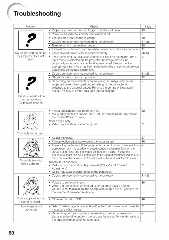
60
Troubleshooting
Problem Check• Projector power cord is not plugged into the wall outlet.• Power to the external connected devices is off.• The selected input mode is wrong.• Cables are incorrectly connected to the projector.• Remote control battery has run out.• External output has not been set when connecting notebook computer.• The lamp unit cover is not installed correctly.• If the connected DVI digital equipment is turned on before the “DVI-D”
input mode is selected on the projector, the image may not beprojected properly or may not be displayed at all. Ensure that theappropriate input mode has been selected on the projector before youturn on the connected equipment.
• Cables are incorrectly connected to the projector.• “Bright” is set to minimum position.• Depending on the computer you are using, an image may not be
projected unless the signal output setting of the computer isswitched to the external output. Refer to the computer’s operationmanual for how to switch its signal output settings.
• Image adjustments are incorrectly set.• Make adjustments of “Color” and “Tint” in “Picture Mode” and lower
the “BrilliantColorTM” value.(Video Input only)• Video input system is incorrectly set.
• Adjust the focus.• The projection distance exceeds the focus range.• There is fog on the lens. If the projector is carried from a cold room into a
warm room, or if it is suddenly heated, condensation may form on thesurface of the lens and the image will become blurred. Set up theprojector at least one hour before it is to be used. If condensation shouldform, remove the power cord from the wall outlet and wait for it to clear.
(Computer Input only)• Perform Synchronization Adjustments (“Clock” and “Phase”
Adjustment)• Noise may appear depending on the computer.• Cables are incorrectly connected to the projector.
• Volume is set to minimum.• When the projector is connected to an external device and the
volume is set to minimum, the sound is not output even if you turn upthe volume of the external device.
• “Speaker” is set to “Off”.
• Select “Data image is not centered” in the “Help” menu and make thenecessary adjustments.
• Depending on the computer you are using, the output resolutionsignal may be different from the one you have set. For details, refer tothe operation manual of the computer.
Page25–3021–25152156, 5721
21–2542–
42
51
2720–
51
–21–25
30
46
51
–
Color is faded or poor.
Picture appears but nosound is heard.
Picture is blurred;noise appears.
Sound is heard but nopicture appears
(or picture is dark).
No picture and no soundor projector does not
start.
Data image is notcentered.
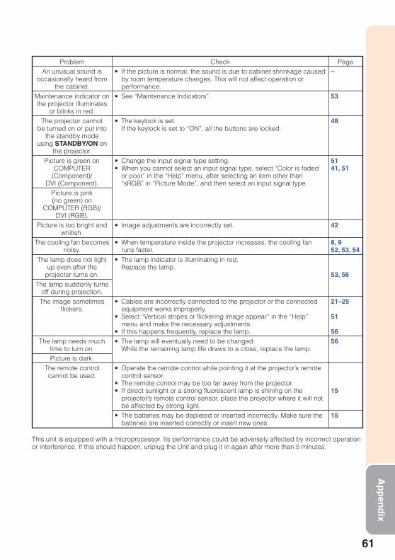
61
Ap
pen
dix
ProblemAn unusual sound is
occasionally heard fromthe cabinet.
Maintenance indicator onthe projector illuminates
or blinks in red.The projector cannot
be turned on or put intothe standby mode
using STANDBY/ON onthe projector.
Picture is green onCOMPUTER
(Component)/DVI (Component).
Picture is pink(no green) on
COMPUTER (RGB)/DVI (RGB).
Picture is too bright andwhitish.
The cooling fan becomesnoisy.
The lamp does not lightup even after the
projector turns on.The lamp suddenly turns
off during projection.The image sometimes
flickers.
The lamp needs muchtime to turn on.Picture is dark.
The remote controlcannot be used.
Check• If the picture is normal, the sound is due to cabinet shrinkage caused
by room temperature changes. This will not affect operation orperformance.
• See “Maintenance Indicators”.
• The keylock is set.If the keylock is set to “ON”, all the buttons are locked.
• Change the input signal type setting.• When you cannot select an input signal type, select “Color is faded
or poor” in the “Help” menu, after selecting an item other than“sRGB” in “Picture Mode”, and then select an input signal type.
• Image adjustments are incorrectly set.
• When temperature inside the projector increases, the cooling fanruns faster.
• The lamp indicator is illuminating in red.Replace the lamp.
• Cables are incorrectly connected to the projector or the connectedequipment works improperly.
• Select “Vertical stripes or flickering image appear” in the “Help”menu and make the necessary adjustments.
• If this happens frequently, replace the lamp.• The lamp will eventually need to be changed.
While the remaining lamp life draws to a close, replace the lamp.
• Operate the remote control while pointing it at the projector’s remotecontrol sensor.
• The remote control may be too far away from the projector.• If direct sunlight or a strong fluorescent lamp is shining on the
projector’s remote control sensor, place the projector where it will notbe affected by strong light.
• The batteries may be depleted or inserted incorrectly. Make sure thebatteries are inserted correctly or insert new ones.
Page–
53
48
5141, 51
42
8, 952, 53, 54
53, 56
21–25
51
5656
15
15
This unit is equipped with a microprocessor. Its performance could be adversely affected by incorrect operationor interference. If this should happen, unplug the Unit and plug it in again after more than 5 minutes.

62
For SHARP Assistance
If you encounter any problems during setup or operation of this projector, firstrefer to the “Troubleshooting” section on pages 60 and 61. If this operation manualdoes not answer your question, please contact the SHARP Service departmentslisted below.
U.S.A. Sharp Electronics Corporation1-888-GO-SHARP (1-888-467-4277)[email protected]://www.sharpusa.com
Canada Sharp Electronics of Canada Ltd.(905) 568-7140http://www.sharp.ca
Mexico Sharp Electronics CorporationMexico Branch(525) 716-9000http://www.sharp.com.mx
Latin America Sharp Electronics Corp. LatinAmerican Group(305) [email protected]://www.siempresharp.com
Germany Sharp Electronics (Europe) GMBH01805-234675http://www.sharp.de
U.K. Sharp Electronics (U.K.) Ltd.08705 274277http://www.sharp.co.uk/customersupport
Italy Sharp Electronics (Italy) S.P.A.(39) 02-89595-1http://www.sharp.it
France Sharp Electronics France01 49 90 35 [email protected]://www.sharp.fr
Spain Sharp Electronica Espana, S.A.93 [email protected]://www.sharp.es
Switzerland Sharp Electronics (Schweiz) AG0041 1 846 63 [email protected]://www.sharp.ch
Sweden Sharp Electronics ( Nordic ) AB(46) 8 [email protected]://www.sharp.se
Austria Sharp Electronics (Europe) GMBHBranch Office Austria0043 1 727 19 [email protected]://www.sharp.at
Benelux SHARP Electronics Benelux BV0900-SHARPCE (0900-7427723)Nederland9900-0159 Belgiumhttp://www.sharp.nlhttp://www.sharp.behttp://www.sharp.lu
Australia Sharp Corporation of Australia Pty.Ltd.1300-135-022http://www.sharp.net.au
New Zealand Sharp Corporation of New ZealandPhone: (09) 573-0111Fax: (09) 573-0112http://www.sharp.net.nz
Singapore Sharp-Roxy Sales (S) Pte. [email protected]://www.sharp.com.sg
Hong Kong Sharp-Roxy (HK) Ltd.(852) [email protected]://www.sharp.com.hk
Taiwan Sharp Corporation (Taiwan)0800-025111http://www.sharp-scot.com.tw
Malaysia Sharp-Roxy Sales & Service Co.(60) 3-5125678
U.A.E. Sharp Middle East [email protected]
Thailand Sharp Thebnakorn Co. [email protected]://www.sharp-th.com
Korea Sharp Electronics Incorporated ofKorea(82) [email protected]://www.sharpkorea.co.kr
India Sharp Business Systems (India)Limited(91) 11- [email protected]

63
Ap
pen
dix
Specifications
As a part of policy of continuous improvement, SHARP reserves the right to make design andspecification changes for product improvement without prior notice. The performance specifica-tion figures indicated are nominal values of production units. There may be some deviations fromthese values in individual units.
ModelDisplay devicesResolutionLens
Input terminals
Output terminals
Control and communication terminals
SpeakersProjection lampRated voltageRated frequencyInput currentPower consumption (Standby*)
Operation temperatureCabinetDimensions (main body only) [W × H × D]
Weight (approx.)
F numberZoomFocusDVI-I (Compatible with HDCP)Computer/Component(mini D-sub 15 pin)
S-Video (mini DIN 4 pin)Video (RCA)Audio (ø3.5 mm stereo minijack)Audio (RCA)Computer/Component(mini D-sub 15 pin)
Audio (ø3.5 mm stereo minijack)LAN (RJ-45)USB (Type B)RS-232C (mini DIN 9 pin)
PG-F255W0.65" DLP® ChipWXGA (1280 × 800)F 2.5 – 2.6Manual, ×1.15 (f = 20.4 – 23.5 mm)Manual×1×1
×1×1×1×1 (L/R)×1
×1 (variable audio output)×1×1×12 W (Mono)200 WAC 100 – 240 V50/60 Hz2.9 A267 W (10.5 W) with AC 100 V259 W (11.0 W) with AC 240 V41°F to 95°F (+5°C to +35°C)Plastic10 41/64" × 3 33/64" × 10 7/16" (270 × 89 × 265 mm)
6.4 lbs. (2.9 kg)
*Standby Mode: Standard

64
Dimensions
Units: inches (mm)
3 33
/64
(89) 1
31/6
4
(37.
65)
2 5 /
8 (6
6.35
)
2 61/64 (75)
10 41/64 (270)
2 3/8 (60)
10 7 /
16 (
265)
1 /4
(6)
13/3
2 (1
0)
M4 M4
M4 M4
4 7 /
64 (
104)
1 15
/16
(49)
13/32 (10) 13/32 (10)
1 3 /
16
(30)
2 61/64 (75)1 27/64(36)

65
Ap
pen
dix
Accessories ............................................................. 11AC socket ................................................................ 25Adjustment buttons ................................................. 39AREA ZOOM ........................................................... 32Aspect ratio ............................................................. 31Audio Input .............................................................. 47AUDIO 1, 2 terminal ................................................ 23AUDIO OUT terminal .............................................. 23Auto Power Off ........................................................ 46Auto Restart ............................................................ 46Auto Sync (Auto Sync adjustment) ....... 34, 38, 46, 51AUTO SYNC button ................................................. 34AV MUTE button ...................................................... 30
Background ............................................................. 45Batteries .................................................................. 15Blue .......................................................................... 42BREAK TIMER button ............................................. 33Bright ....................................................................... 42BrilliantColorTM ......................................................... 42
CLR Temp (Color Temperature) .............................. 42C.M.S. ...................................................................... 42Color ........................................................................ 42COMPUTER button ................................................. 30COMPUTER/COMPONENT input terminal ...... 21, 22Contrast ................................................................... 42
DHCP Client ............................................................ 50DIN-D-sub RS-232C adaptor .................................. 24DNR ......................................................................... 43DOT BY DOT ........................................................... 31DVI button ................................................................ 30DVI-I input terminal ........................................... 21, 22
ECO+QUIET button ................................................ 33ENTER button ......................................................... 39Exhaust vent ...................................................... 12, 52
Fan Mode ................................................................. 47Focus ring ................................................................ 27FREEZE button ....................................................... 34Front adjustment foot .............................................. 28FULL ........................................................................ 31
HEIGHT ADJUST lever ........................................... 28Help ......................................................................... 51H-Pos ................................................................. 38, 51
Image shift ............................................................... 44INPUT modes .......................................................... 30Intake vent ......................................................... 12, 52
Kensington Security Standard connector ............... 13Keycode ................................................................... 47Keylock .................................................................... 48KEYSTONE button .................................................. 29Keystone Correction .......................................... 29, 44
Lamp ........................................................................ 55Lamp indicator ......................................................... 53Lamp Setting ........................................................... 43Lamp Timer (Life) .................................................... 48Lamp unit ................................................................. 56Language (on-screen display language) ................ 45LAN terminal ............................................................ 25L-CLICK/EFFECT button .................................. 33, 35Lens Cap ................................................................. 12
Index
MAC Address .......................................................... 50MAGNIFY buttons ................................................... 34MENU/HELP button .......................................... 39, 51MONITOR OUT terminal ......................................... 23MOUSE/Adjustment buttons ............................. 35, 39
Network ................................................................... 49NORMAL ........................................................... 31, 32
ON button ................................................................ 26Optional accessories ............................................... 11OSD Display ............................................................ 44
PAGE DOWN button ................................................ 35PAGE UP button ...................................................... 35Password ................................................................. 49PDF .......................................................................... 10Picture Adjustment .................................................. 41Picture Mode ..................................................... 34, 41PICTURE MODE button .......................................... 34POINTER button ..................................................... 33Power cord ............................................................... 25Power indicator ........................................................ 53PRJ - ADJ ................................................................ 46PRJ Mode .......................................................... 19, 45Progressive .............................................................. 43
R-CLICK/RETURN button ................................. 35, 39Rear adjustment foot ............................................... 28Red .......................................................................... 42Remote control ........................................................ 14Remote control sensor ............................................ 15Replacing the lamp ........................................... 55, 56Resize ................................................................ 31, 44RESIZE button ........................................................ 31RGB cable ............................................................... 21RS-232C terminal .................................................... 24
SCR - ADJ ............................................................... 44Screen Size and Projection Distance ..................... 20Setup Guide ....................................................... 27, 45Sharp ....................................................................... 42Speaker ................................................................... 46SPOT button ............................................................ 33STANDBY button ..................................................... 26STANDBY Mode ...................................................... 46STANDBY/ON button .............................................. 26Storage case ........................................................... 58STRETCH .......................................................... 31, 32Supplied accessories .............................................. 11S-VIDEO button ....................................................... 30S-VIDEO terminal .................................................... 22System Lock ............................................................ 47System Sound ......................................................... 46
TCP/IP ..................................................................... 50Temperature warning indicator ............................... 53Tint ........................................................................... 42
USB terminal ........................................................... 35
VIDEO button .......................................................... 30VIDEO terminal ....................................................... 22VOL (Volume) buttons ............................................. 30V-Pos ................................................................. 38, 51V-STRETCH ............................................................ 32
Zoom ring ................................................................ 27