MODEL NUMBER 917.259565 OWNER'S MANUAL · with a spark arrester meeting applicable local or state...
56
C MODEL NUMBER 917.259565 OWNER'S MANUAL ® • Assembly • Operation • Customer Responsibilities • Service and Adjustments • Repair Parts For answers to your questions about this product, Call: 1-800-659-5917 Sears Craftsman Help Line 5 am - 5 pro, Mot) - Sat CAUTION: Read and follow all safety rules and instructions before operating this equipment. FOR CONSUMER ASSISTANCE HOT LINE, CALL THIS TOLL FREE NUMBER: 1-800-659-5917 m_
Transcript of MODEL NUMBER 917.259565 OWNER'S MANUAL · with a spark arrester meeting applicable local or state...

CMODEL NUMBER 917.259565 OWNER'S MANUAL
®
• Assembly• Operation• Customer Responsibilities• Service and Adjustments• Repair Parts
For answers to your questionsabout this product, Call:
1-800-659-5917Sears Craftsman Help Line5 am - 5 pro, Mot) - Sat
CAUTION: Read and follow all safety rules and instructions before operating this equipment.FOR CONSUMER ASSISTANCE HOT LINE, CALL THIS TOLL FREE NUMBER: 1-800-659-5917
m_
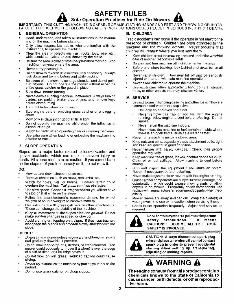
SAFETY RULESSafe Operation Practices for Ride-On MowersIMPORTANT: THIS CUTTING MACHINE IS CAPABLE OFAMPUTATING HANDS AND FEET AND THROWING OBJECTS.FAILURE TO OBSERVE THE FOLLOWING SAFETY INSTRUCTIONS COULD RESULT IN SERIOUS iNJURY OR DEATH.
I. GENERAL OPERATION
• Read, understand, and follow all instructions in the manualand on the machine before slarting.
• Only allow responsible adults, who are familiar with theinstructions, to operate the machine.
• Clear the area of objects such as rocks, toys, wire, etc.,which could be picked up and thrown by the blade.
• Be sure the area is clear of other people before mowing. Stopmachine if anyone enters the area.
• Never carry passengers.
• Do not mow in reverse unless absolutely necessary. Alwayslook down and behind before and while backing.
• Be aware of the mower discharge direction and do net pointit at anyone. Do not operate the mower without either theentire grass catcher or the guard in place.
• Slow down before turning.• Never leave a running machine unattended. Always turn off
blades, set parking brake, stop engine, and remove keysbefore dismounting.
• Turn off blades when not mowing.• Stop engine before removing grass catcher or unclogging
chute.
• Mow only in daylight or good artificial light.• Do not operate the machine while under the influence of
alcohol or drugs.• Watch for traffic when operating near or crossing roadways.° Use extra care when loading or unloading the machine into
a trailer or truck.
II. SLOPE OPERATION
Slopes are a major factor related to loss-of-control andtipover accidents, which can result in severe injury ordeath. All slopes require extra Caution. If you cannot backup the slope or if you feel uneasy on it, do not mow it.
DO:
• Mow up and down slopes, not across.° Remove obstacles such as rooks, tree limbs, etc.
• Watch for holes, ruts, or bumps. Uneven terrain couldoverturn the machine. Tall grass can hide obstacles.
• Use slow speed. Choose a low gear so that you will not haveto stop or shift while on the slope.
• Follow the manufacturer's recommendations for wheelweights or counterweights to improve stability.
• Use extra care with grass catchers or other attachments.These can change the stability of the machine.
• Keep all movement on the slopes slowand gradual Do notmake sudden changes in speed or direction.
• Avoid starting or stopping on a slope. If tires lose traction,disengage the blades and proceed slowly straight down theslope.
DO NOT:
• Donot turn on slopes unless necessary, andthen, turn slowlyand gradually downhill, if possibIe.
° Do not mow near drop-offs, ditches, or embankments. Themower could suddenly turn over if a wheel is over the edgeof a cliff or ditch, or if an edge caves in.
• Do not mow on wet grass. Reduced traction could causesliding.
• Do not try to stabilize the machine by putting your foot on theground.
• Do not use grass catcher on steep slopes.
2
III. CHILDREN
Tragic accidents can occur if the operator is not alert to thepresence of children. Children are often attracted to themachine and the mowing activity, Never assume thatchildren will remain where you last saw them.
° Keep children out of the mowing area and under the watchfulcare of another responsible adult.
• Be alert and turn machine off if children enter the area.
• Before and when backing, look behind and down for smallchildren.
• Never carry children. They may fall off and be seriouslyinjured or interfere with safe machine operation.
° Never allow children to operate the machine.° Use extra care when approaching blind corners, shrubs,
trees, or other objects that may obscure vision.
IV. SERVICE
• Use extra care in handling gasoline and other fuels. They areflammable and vapors are explosive.
Use only an approved container.Never remove gas cap or add fuel with the enginerunning. Allow engine to cool before refueling. Do notsmoke.Never refuel the machine indoors.Never store the machine or fuel container inside wherethere is an open flame, such as a water heater.
• Never run a machine inside a closed area.
• Keep nuts and bolts, especially btade attachment bolts, tightand keep equipment in good condition.
• Never tamper with safety devices. Check their properoperation regularly.
• Keep machine free of grass, leaves, or other debds build-up.Clean oil or fuel spillage. Allow machine to cool beforestoring.
• Stop and inspect the equipment if you strike an object.Repair, if necessary, before restarting.
• Never make adjustments or repairs with the engine running.° Grass catcher components are subject to wear, damage, and
deterioration, which could expose moving parts or altowobjects to be thrown. Frequently check components andreplace with manufacturer's recommended parts, when nec-essary.
• Mower blades are sharp and can cut. Wrap the blade(s) orwear gloves, and use extra caution when servicing them.
• Check brake operation frequently. Adjust and service asrequired.
Look for this symbol to point out importantsafety precautions. It meansCAUTION!l! BECOME ALERT!!! YOURSAFETY IS INVOLVED.
I
CAUTION: Always disconnect spark plug IA wire and place wire where it cannot contact I
spark plug in order to prevent accidental Istarting when setting up, transporting, I
adjusting or making repairs,
WARNINGThe engine exhaust from this product containschemicals known to the State of California tocause cancer, birth defects, or other reproduc-tive harm.

CONGRATULATIONS on your purchase of a SearsTractor. it has been designed, engineered and manufac-tured to give you the best possible dependability andperformance.Should you experience any problem you cannot easilyremedy, please contact your nearest Sears AuthorizedService Center/Department. We have competent, well-trained technicians and the proper tools to service or repairthis tractor.Please read and retain this manual. The instructions willenable you to assemble and maintain your tractor properly.Always observe the "SAFETY RULES".
MODEL
NUMBE R 917.259565
SERIALNUMBER
DATE OF PURCHASE
THE MODEL AN D SERIAL NUMBERS WILL BE FOUND
i ON A PLATE UNDER THE SEAT.
YOU SHOULD RECORD BOTH SERIAL NUMBER AND
DATE OF PURCHASE AND KEEP IN A SAFE PLACE
FOR FUTURE REFERENCE.
MAINTENANCE AGREEMENTA Sears Maintenance Agreement is available on this prod-uct. Contact your nearest Sears store for details,
CUSTOMER RESPONSIBILITIES• Read and observe the safety rules.
o Foltow a regular schedule in maintaining, caring for andusing your tractor.
- Follow the instructions under"Customer Responsibili-ties" and "Storage" sections of this owner's manual.
WARNING: This tractor is equipped with an internalcombustion engine and should not be used on or near anyunimproved forest-covered, brush-covered or grass-cov-ered land unless the engine's exhaust system is equipped
PRODUCT SPECIFICATIONSHORSEPOWERi 19.5
GASOLINE CAPACITY 3°5 GALLONSAND TYPE: UNLEADED REGULAR
OiL TYPE (APt-SF/SG/SH): SAE 30 (above 32°F)SAE 5W-30 (below 32°F)
OIL CAPACITY: 3.0 PINTS
SPARK PLUG: CHAMPION RJ19LM(GAP: .030")
VALVE CLEARANCE: iNTAKE: .004" - .006"EXHAUST: °007" - .009"
GROUND SPEED (MPH): FORWARD:1st 1.12rid 1,43rd 2.34th 3.55th 4.56th 5.7
REVERSE: 1.8
TIRE PRESSURE: FRONT: 14 PS!REAR: 10 PSI
CHARGING SYSTEM: 3 AMPS BATTERY5 AMPS HEADLIGHTS
BATTERY: AMP/HR: 30
MIN. CCA: 240CASE SIZE: U1R"
BLADE BOLT TORQUE: 30-35 FT. LBS.
with a spark arrester meeting applicable local or state laws(if any). If a spark arrester is used, it should be maintainedin effective working order by the operator.In the state of California the above is required by law(Section 4442 of the California Public Resources Code),Other states may have similar laws. Federal laws apply onfederal lands. A spark arrester for the muffler is availablethrough your nearest Sears Authorized Service Center/Department (See REPAIR PARTS section of this manual).
LIMITED TWO YEAR WARRANTY ON CRAFTSMAN RIDING EQUIPMENTFor two (2) years from the date of purchase, if this Craftsman Riding Equipment is maintained, lubricated and tuned up accordingto the instructions in the owner's manual, Sears will repair or replace, free of charge, any parts found to be defective in material orworkmanship.This Warranty does not cover:
Expendable items which become worn during normal use, such as blades, spark plugs, air cleaners, belts, etc:• Tire replacement or repair caused by punctures from oulside objects, such as nails, thorns, stumps, or glass.
Repairs necessary because of operator abuse, negligence, improper storage or accident or the failure to maintain theequipment according to the instructions contained in the owner's manual.
• Riding equipment used for commercial or rental purposes.
LIMITED 90 DAY WARRANTY ON BATTERYFor ninety (90) days from date of purchase, if any battery included with this riding equipment proves defective in material orworkmanship and our testing determines the battery will not hold a charge, Sears will replace the battery at no charge.
IN-HOME WARRANTY SERVICE ON YOUR CRAFTSMAN RIDING EQUIPMENT IS AVAILABLE AT NO-CHARGE FOR 30DAYS FROM THE DATE OF PURCHASE. PLEASE CONTACT YOUR NEAREST SERVICE CENTER. AFTER 30 DAYS FROMTHE DATE OF PURCHASE, WARRANTY SERVICE IS AVAILABLE BY TAKING YOUR CRAFTSMAN RIDING EQUIPMENT TOYOUR NEAREST SEARS SERVICE CENTER. (iN-HOME WARRANTY SERVICE WILL STILL BE AVAILABLE AFTER 30 DAYSFROM THE DATE OF PURCHASE BUT A STANDARD TRIP CHARGE WILL APPLY.) THIS WARRANTY APPLIES ONLYWHI LE THIS PRODUCT IS IN THE UNITED STATES.
This Warranty gives you specific lega! rights, and you may also have other rights which may vary from state to state.
SEARS, ROEBUCK AND CO., D/817 WA, HOFFMAN ESTATES, IL 60179
3
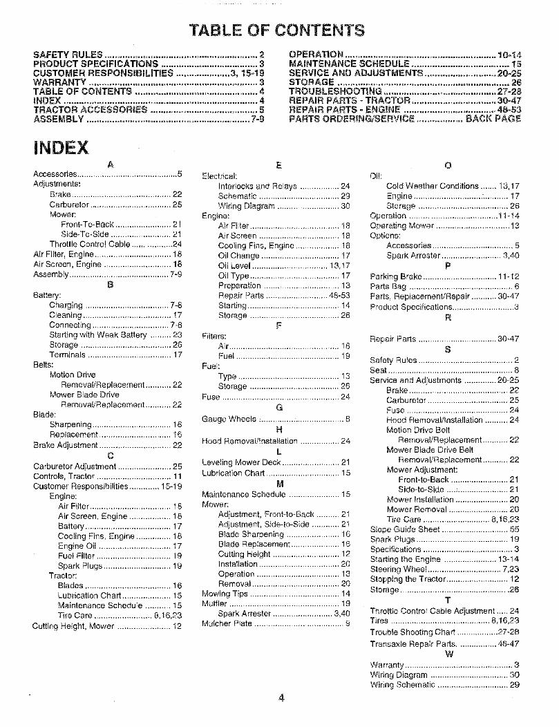
TABLE OF CONTENTS
SAFETY RULES ............................................................ 2PRODUCT SPECIFICATIONS ...................................... 3CUSTOMER RESPONSIBILITIES ..................... 3, 15-19WARRANTY .................................................................. 3TABLE OF CONTENTS ................................................ 4INDEX ............................................... ,............................ 4TRACTOR ACCESSORIES .......................................... 5ASSEMBLY ................................................................ 7-9
OPERATION ........................................................... 10=14MAINTENANCE SCHEDULE ...................................... 15SERVICE AND ADJUSTMENTS ............................ 20-25STORAGE ................................................................... 26TROUBLESHOOTING ............................................ 27-28REPAIR PARTS - TRACTOR .................................. 30-47REPAIR PARTS oENGINE .................................... 48-53PARTS ORDERING!SERVICE .................. BACK PAGE
INDEXA
Accessories ............................................ 5
Adjustments:Brake ........................................... 22Carburetor ................................... 25Mower'.
Front-To-Back ................. i...... 21
Side-To-Side .......................... 21Throttle Control Cable ................. 24
Air Filter, Engine ................................. 18Air Screen, Engine ............................ 18Assembly ........................................... 7-9
BBattery:
Charging .................................... 7-8
Cleaning ...................................... 17Connecting ................................. 7-8Starting with Weak Battery ......... 23Storage ....................................... 26Terminals .................................... 17
Belts:Motion Drive
Removal/Replacement ........... 22Mower Blade Drive
Remova!/Replacement ........... 22Blade:
Sharpening .................................. 16Replacement ............................... 16
Brake Adjustment ............................... 22C
Carburetor Adjustment ....................... 25Controls, Tractor ................................ 11Customer Responsibilities ............. 15-19
Engine:Air FiLter................................... t 8
Air Screen, Engine .................. 18Battery ..................................... 17Cooling Fins, Engine ............... 18Engine Oil ............................... 17Fuel Filter ................................ 19
Spark Plugs ............................. 19Tractor:
Blades ..................................... 16Lubrication Chart ..................... 15Maintenance Schedule ........... 15
Tire Care ......................... 8,16,23
Cutting Height, Mower ....................... t2
E
Electrical:
Interlocks and Relays ................. 24Schematic ................................... 29
Wiring Diagram .......................... 30Engine:
Air Filter ....................................... 18Air Screen .................................. 18
Cooling Fins, Engine ................... 18Oil Change .................................. 17Oil Level ................................. 13,17Oil Type ....................................... 17Preparation ................................. ! 3Repair Parts ........................... 48-53Starting ....................................... 14Storage ....................................... 26
F
Filters:Air ................................................ 18Fuel ............................................. 19
Fuel:
Type ............................................ 13Storage ....................................... 26
Fuse ................................................... 24
G
Gauge Wheels .................................... 8H
Hood Removal/Installation ................. 24
L
Leveling Mower Deck ......................... 21Lubrication Chart ................................ 15
MMaintenance Schedule ...................... 15Mower:
Adjustment, Front-to-Back .......... 2IAdjustment, Side-to-Side ............ 2tBlade Sharpening ....................... 16Blade Replacement ..................... 16Cutting Height ............................. 12Installation ................................... 20
Operation .................................... 13Removal ...................................... 20
Mowing Tips ....................................... 14Muffler ............................................... 19
Spark Arrester .......................... 3,40Mulcher Plate ....................................... 9
4
OOil:
Cold Weather Conditions ....... I3,17
Engine ............................ :........... 17Storage ....................................... 26
Operation .................................... t 1-14Operating Mower ................................ t3Options:
Accessories ............................... ,,, 5
Spark Arrester .......................... 3,40P
Parking Brake ................................ 11-12Parts Bag ............................................. 6Parts, Rep_acemenVRepair ........... 30-47Product Specifications ........................... 3
R
Repair Parts .................................. 30-47S
Safety Rules ......................................... 2Seat ...................................................... 8
Service and Adjustments .............. 20-25Brake ........................................... 22Carburetor ................................... 25Fuse ........................................... 24Hood Removal/Installation .......... 24Motion Drive Belt
Removal/Replacement ........... 22Mower Blade Drive Belt
Removal/Replacement ........... 22Mower Adjustment:
Front-to-Back ......................... 21Side-to-Side ....: ...................... 21
Mower Installation ....................... 20Mower Removal .......................... 20
Tire Care ............................. 8,16,23Slope Guide Sheet ............................. 55Spark Plugs ........................................ 19Specifications ....................................... 3Starting the Engine ....................... 13-14Steering Wheel ................................ 7,23Stopping the Tractor ........................... 12Storage ............................................... 26
T
Throttle Control Cable Adjustment ..... 24Tires ........................................... 8,16,23
Trouble Shooting Chart .................. 27_28
Transaxle Repair Parts ................. 46-47W
Warranty ............................................... 3Wiring Diagram .................................. 30Wiring Schematic ............................... 29

IES"Theseaccessories and attachments were available through most Seers retait outlets end service centers when the tractor was purchased:Most Sears stores can order these items for you when you provide the model number of your tractor,
ENGINE
SPARK PLL_G GAg CAN ENGINE OiL FUEL STABtUZER AJR FtLTEFI BLADES BELTS
PERFORMANCE
Sears offers a wide variety of attachments that fit your tractor. Many of these are Iisted be!ow with brief explanatio_-_eof how they can helpyou. This list was current at the time of puMicafion; however, it may change in future years - more attachments may be added, changesmay be made in these attachments, or some may no longer be avaitab{e or fit your model Contacl yo_ r_arest See_'s store for theaccessories and attachments that are available for your tractor.
Most of these attachments do not require additional hitches or conversion kits (those that do are indicated) and are designed for easyattaching and detaching,
AERATOR promotes deep root growth for a healthy' lawn. Ta-pered 2.5-inch steei spikes mounted on 10-inch diameter discspuncture holes in soil at close intervals to let moisture soak in.Steel weight tray for increased penetration.
BAGGER lets you collect grass clippings and leaves for ahealthier, nearer looking iawn Two Permanex containers hold30-gallon plastic bags.
BUMPER protects front end of tractor from damage.
CARTS make hauling easy. Variety of sizes avai}able, piusaccessories such as side pane_ kits, toot caddy, cart cover,protective mot and deity.
COR_NG AERATOR takes small plugs out of soil to allow mois-ture and nutrients to reach grass roots. 36qnch swath. 24hardened steel coring tips. 150 lb. capacity weight tray.
EASY O_L.DRAIN VALVE makes oil changes easier, faster.FRONT NOSE ROLLER canters in front of mower deck to reducechances of "sca_ping" on uneven terrain.
GANG H_TCH lets you tow 2 or 3 putt-behind attachments at once,such as sweepers, dethatchers, aerators (not for use with rollers,carts or other heavy attachments).GAUGE WHEELS on both sides of the mower dock reducechances of "scalping" on uneven terrain. For mower decks not soequipped.
MULCH RAKE/DETHA'FCHER loosens soil and flips thatch andmalted leaves to [awn surface for easy pickup. Twenty spring fineteeth. Usefultopreparebaroareasforseeding. Available for frontor rear mounting. H_GR PERFORMANCE REEL-ACTIONSPRING T_NE OETRATCNER covers 36-inch wide path andtosses thatch into large hopper. Mounts behind tractor.
MULCHNG CLOSE-OUT PLATE K_T, once installed, lets youmulch, discharge or bag clippings (bagger optional) withoutch_._ngingblades. For models not equipped as 3-inol Convertiblemowers. See "MOWER" in the Repair Parts section of thismanual
RAMP TOPS AND FEET Jet you load and unload tractor from apickup truck. Use with 2 x 8 or 2 x 10 lumber.
ROLLER for smoother Jawn surface. 36-inch wide, 18-inchdiameter water4ight drum holds up to 390 lbs. of weight. Roundededges prevent harm to tuff. Adjustable scraper automaticallyc_eans drum,
SNOWBLADEforsnowmmova!on_y. 14-inch high,484nchwideblade clears 42-inch path when angled left or right Raises_ lowerswith side lever, Adiustable skids; _eplaceabie reversible Scraperbar. (Use with tire chains and wheel weights a_ld/or rear drawbarweight.)
SNOWTHROWER has 40qnch swath, Drum-type auger handlespowdery and we_Jheevy snow. Mounts easiiy wi_h simple pina_rangement. Discharge chute adjusts from tractor seat. 64nchdiameter spout disct_arges snow 10 to 50 feet. Lift controlled attractor seat. (Use with chains and wheel weights and!or reardrawbar weight,)SPRAYERS use 12-vott DO etectdc motor that connects to thetractor battery or other 12-vo_t source. Includes booms forautomatic spraying and hand hetd wand for spot spraying. Wandhas adiustable spray pattern. For applying herbicides, insecti-cides, fungicides and liquid fertilizers,
SPREADE_S_DERS make seeding, fertilizing, and weed kill-ing easy. Broadcast spreaders are a_so useful for granular de-icers and sand.
SWEEPERS Jet you coltect grass c|ippings and leaves.
T_LLER has 5 hp engine and 36-inch swath to prepare seed beds,cultivate and compost garden residue. Tiller has its own built-inlift and depth control system and does NO'[ require a sleeve hitch.Fits any lawn, yard or garden tractor. Simpty hook up to the tractordrawbar and go! Optional accessories convert unit fordethatching, aerating, hilling_,,without toots.
TIRE CHAINS are heavy duty; c_ose_yspaced extraolarge crosslinks give smooth ride, outstanding traction.
TRACTOR CAB has heavy duty vinyl fabdc over tubular steelframe, ABS plastic top; clear plastic windshield offers 360 degreevisibility, Hinged metal doors with catch_ Keeps operator warmand dry. Remove vinyi sides and windshields for use as sunprotector in summer. Optiona! accessories ir_c_ude: tinted!tempered solid safety glass windshield with hand operated wiper;12-vott amber caution light for mounting on cab top.
VACS for powedu{ collection of heavy grass clippings and leaves.Opt_o_a_ wand a_achme_t to pick up debris in hard4o-reachplaces. VAC/CN_PRER includes e chipper_shredder.WEIGHT BRACKET for drawbar for snow removal applications.Uses (!) 55 Iboweight.
WHE_L WEIGHTS {or rear wheels provide needed traction forsnow remova! or dozing heavy materials.
5

CONTENTS OF HARDWA PACK
Parts Bag contents shown full size
(1) Hex Bolt3/8-16 x 1
\
o i/
(1) Large Flat Washer (1) Lockwasher 3/8
(1) Hex Bolt 5/16-18 x 1-1/4 (1) kocknut 5/16-18
r (1) Hex BoltI"' Bolt 5/16-18 1/2-13x 1
(1)Washer d( (A_," i17/32 X -_1-3/16.x 12
Gauge _/" /
(1) Lock Washer 1/2
._(2) Lock_. Washers
_/ \ #10L _ )(2) Washers_. / 3/16 x3/4
x 16 Gauge
(2) Screws#10 x 5/8
(2) WeldNuts #10
(2) Hex Bolts 1/4-20 x 3/4
(2) Hex Nuts 1/4-20
[2) Washers 9/32 x 5/8 x 16 GaugeLock Washers 1/4
Parts packed separately in carton
Seat
VideoCassette
SteeringWheel Mulcher
Plate
Parts Bag
SteeringBoot
Manua_
Parts bag contents not shown full size
(2) ShoulderBolts
Steering WheelAdapter
(2) Washers 3/8x 7/8 x 14 Gauge
(2) Center-lock Nuts
2) Latch Hook
Assemblys
/
L
(2) GaugeWheels
J ......... -,, (2) Keys
" / Steering\/ /
........../ Wheel,_ 1 Insert
Slope Sheet
SteeringExtensionShaft

ASSEMYour new tractor has been assembled at the factory with exception of those paris left unassembied for shipping purposes_To ensure sate and proper operation of your tractor all parts and hardware you assemble must be tightened securely. Usethe correct tools as necessary lo insure proper tightness.
TOOLS REQUIRED FOR ASSEMBLYA socket wrench set witt make assembly easier. Standardwrench sizes are listed(1} 3/4" Socket w/drive rachet(2) 7/16" wrenches Phillips Screwdriver(2) 1/2" wrenches Tire pressure gauge(t) 9/t6 _wrench Utility knifeWhen right or left hand is mentioned in this manual, itmeans when you are in the operating position (seatedbehind the steering wheel).
TO REMOVE TRACTOR FROM CARTONUNPACK CARTON
Remove all access#ble toose parts and parts cartonsfrom carton (See page 6).
,, Cut, _rom top to bottom, along lines on all four cornersof carton, and lay panels flat.
,, Cheek for any additional toose parts or cartons andremove
BEFORE ROLUNG TRACTOR OFF SKID
A_ACH STEERING WHEEL {See Fig. 1)ASSEMBLE EXTENSION SHAFT AND BOOT
Slide extension shaft onto lower steering shaft. Alignmounting holes in extension and lower shafts andinstall 5/!6 he× bolt and Iocknut. Tighten securely.
IMPORTANT: TIGHTEN BOLT AND NUT SECURELY TO18-22 FT LBS TORQUE.
Ptace tabs of steering boot over tab slots in dash andpush down to secure_
INSTALL STEERING WHEEL
. Position front wheels of the tractor so they are pointingstraig ht forward.
Slide steering wheel adapter onto steering shaft exten-sion.
Position steering wheel so cress bars are horizontal(left to right} and slide inside boot and onto adapter.
Assemble large flat washer, 3/8 lock washer, 3/8 hexbott and tighten seourely_
Snap steering wheel insert into center of steeringwheel
• Remove protective materials from tractor hood andgrill
IMPORTANT: CHECK FOR AND REMOVE ANY STAPLESlN SK!D THAT MAY PUNCTURE TIRES WHERE TRACTORIS TO ROLL OFF SKID,
, _:\
.- <
_UNSERT
WASHER
STEERINGBOOT
ADAPTER
EXTENSION SHAFT
5/I6 HEX BOLT
FIGo 1
TO ROLL TRACTOR OFF SKiD (See Operationsection for location and function of controls)
Press lift tever plunger and raise attachment lift lever toits Nghest position.
o Release parking brake by depressing clutch/brakepedal.Place gearshift lever in neutra_ (N) position.Roll tractor backwards off skid.
• Remove banding holding discharge guard up againsttractor.
7

BLYHOW TO SET UP YOUR TRACTORCONNECT BATTERY (See Fig. 2)
CAUTION: Do not short b_ttery termi-nals by a|iowing a wrench or any otherobject to contact both terminals _ thesame time, Before connecting battery,remove metal bracelets, wristwatchbands, rings, etc.Positive terminal must be connectedfirst to prevent sparking from acciden_talgrognding,
Lifthood toraisedposition
- Open terrnif_ai access doors, remove terminal protec-tive caps and discard.If this battery is put dnto service after month and yearindicated on label (label located between terminals)charge battePj for minimum of one hour at 6-10 amps.
,, First connect RED battery cable to positive (+) batteryterminal with hex bolt, fiat washer, lock washer and hexnut as shown. Tighten securely.
* Connect BLACK grounding cable to negative (-) bat-tery terminal with remaining hex ooit, fiat washer, lockwasher and hex nut. Tighten securely.Close terminal access doors.
Use terminal access doors for:Inspection for secure connections (to tighten hard-ware).Inspection for corrosion.Testing battery.Jumping (if required).Periodic charging.
LOCK FLATDISCARD TERMINAL WASHER WASHERPROTECTIVE CAPS HEX NUT
FIG. 2
INSTALL SEAT (See Fig. 3)Adjust seat before tightening adjustment bott.• Remove cardboard packing on seat pan.
Place seat on seat pan and assemble shoulder bolt.Tighten shoulder bolt securely.
, Assemble adjustment bolt, Iockwasher and flat washertooseJy_ Do not tighten.
• Lower seat into operating position and sit on seat.
, Slide seat until a comfortable position is reached whichallows you to press clutch/brake pedal all the waydown.
Get off seat without moving its adjusted position.
"_ Raise seat and tighten adjustment bolt securely.
SEAT
\
F_Go3
CHECK T!RE PRESSUAE
The tires on your tractor were overinftated at the factory, forshipping purposes. Correct tire pressure is important forbest cutting performance., Reduce tire pressure to PSi shown in "PRODUCT
SPECIFICATIONS" on page 3 of this manual.
CHECK DECK LEVELNESS
For best cutting lesults, mower housing should be properlyleveled. See "TO LEVEL MOWER HOUSING" in theService and Adjustments section of this manual
CHECK FOR PROPER POSITION OF ALLBELTSSee the figures that are shown for replacing motion andmower blade drive belts in the Service and Adjustmentssection of this manual. Verify that the belts are routedcorrectly.
CHECK BRAKE SYSTEM
After you Iearn how to operate your tractor, check to seethat the brake is properly adjusted. See "TO ADJUSTBRAKE" in the Sewice and Adjustments section of thismanual.
ASSEMBLE GAUGE WHEELS TO MOWERDECK (See Fig. 4)
The gauge wheels are designed to keep the mower deck inproper position when operating mower Be sure they areproper!y adjusted to ensure optimum mower performance.
Assemble gauge wheels with tractor on a flat levelsurface
,, Adjust mower to desired cutting height (See "TO AD-JUST MOWER CUTTING HEIGHT" in the Operationsection of this manual)
With mower in desired height of cut position, gaugewheels should be assembled so they are slightly off theground, install gauge wheel in appropriate hole withshoulder bolt, 3/8 washer, and 3/8-16 Iocknut andtighten securely.
o Repeat for opposite side installing gauge whee! insame adjustment hole.

ASSE
GAUGE WHEELMOUNTINGBRACKET
318-! 6LOOKNUT
3t8" WAS_-_ER
GAUGE WHEEL
\\
SHOULDER BOLT
FIG° 4
iNSTALL MULCHER PLATE(See Figs° 5 & 6)
o !nstall two tatch hooks to mulcher plate using screw,washer, lock washer, and weld nut as shown.
NOTE: Pre-assemble we_d nut to latch hook by insertingweld nut from the top with hook pointing down.
o Tighten hardware securely.
,, Raise and held deflector shieid in upright position.
Place front of mulcher plate over front of mower deckopening and slide into place, as shown.
o Hook front latch into hole on front of mower deck.
Hook rear latch into hole on back of mower deck.
CAUTION: Do not remove dischargeguard from mower. Raise and holdguard when attaching muleher plateand at_ow it to rest on plate while inoperation.
WELD NUT FROM THE TOP HOOK POINTS DOWN
\,
WASHER
LATCHHOOK
TO CONVERT TO BAGGING ORDISCHARGING
Simply remove mulcher plate and store in a safe place.Your mower is now ready for discharging or installation ofoptional grass catcher accessory.
DEFLECTORSH
FiG. 6
,/CHECKMSTBEFORE YOU OPERA TE AND ENJOY YOUR NEWTRACTOR, WE WISH TO ASSURE THAT Y'OURECEIVETHE BEST PERFORMANCE AND SA 77SFACTION FROMTHIS QUALITY PRODUCT.
PLEASE REVIEW THE FOLLOWING CHECKLIS7_"
¢" Atl assembly instructions have been completed.
,/ No remaining toose parts in carton.
¢ Battery is properly prepared and charged. (Minimum1 hour at 6 amps)
,/ Seat is adjusted comfortabIy and tightened securely.
¢" At! tires are properly inflated. (For shipping purposes,the tires were overinfiated at the factory)
/ Be sure mower deck is properly teveled side-to-side/front-to-rear for best cutting results. (Tires must beproperly inflated for leveling).
v" Check mower and drive belts. Be sure they are routedproperly around pulteys and inside all belt keepers.
,/ Check wiring See that al! connections are still secureand wires are properly ctamped_
WHfLE LEARNING HOW 7"0 USE YOUR TRACTOR, PAYEXTRA ATTENTION TO THE FOLLOWING iMPORTANTITEMS:
v" Engine oil {s at proper levet.
,/ Fuel tank is filled with fresh, clean, regular unleadedgasoline.
•/ Become familiar with all controls o their location andfunction. Operate them before you start the engine.
7 Be sure brake system is in safe operating condition.
FiG. 5

OPERATIOThese symbols may appear on your tractor or in literature supplied with the product. Learn and understand their meaning.
E3BATTERY
ENGINE ON
$REVERSE
t
CAUTION OR FORWARD FAST SLOWWARNING
ENGINE OFF OIL PRESSURE CLUTCH LIGHTS ON LIGHTS OFF
FUEL CHOKE MOWER HEIGHT DIFFERENTIALLOCK
REVERSE NEUTRAL HIGH
PARKING BRAKE UNLOCKEDLOCKED
LLOW PARKING BRAKE
MOWER LIFT ATTACHMENTCLUTCH ENGAGED
ATTACHMENTCLUTCH DISENGAGED
IGNITION
DANGER, KEEP HANDS AND FEET AWAYHYDROSTATIC FREE WHEEL
(Hydro Models only)
10

KNOW YOUR TRACTOR
READ THiS OWNER'S MANUAL AND SAFETY RULES BEFORE OPERATING YOUR TRACTOR
Compare the illustrations with your tractor to familiarize yourself with the locations of various controls and adjustments Savethis manual for future reference.
UGHT SW_TOHATTACHMENT IGNmON POS_T_ONCLUTCH LEVER SWITCH
CLUTCH/BRAKEPEDAL
HEEGHTADJUSTMENTKNOB
l-
FIG. 7
Our tractors conform to the safety standards of the American National Standards _nstitute.
ATTACHMENT CLUTCH LEVER: Used to engage themower blades, or other attachments mounted to yourtractor.
LIGHT SWITCH: Turns the headlights on and off
THROTTLE CONTROL: Used to control engine speed.
CHOKE CONTROL: Used when starting a cold engine.
CLUTORtBRAKE PEDAL: Used for declutching and brak-ing the tractor and starting the engine.
PARKING BRAKE: Lacks clutch/brake pedal into thebrake position
GEARSHIFT LEVER: Selects the speed and direction oftractor.
ATTACR_.,_ENT LiFT LEVER: Used to raise and lower themower deck or other attachments mounted to your tractor.L_Fr LEVER PLUNGER: Used to release attachment liftlever when changing its position.
IGNRTDONSW_TCH: Used for starting and stopping theengine.
HEmGHTADJUST[_ENT KNOB: Used to adjust the mowercutting height,
AMMETER: Indicates battery charging (+) or discharging(-).
11

oreign obj_
__e. Always wear safety glass_te operating your J_justments or repairs. We rec_._ion _afety mask
over th
HOW TO USE YOUR TRACTOR
TO SET PARKING BRAKE {See Fig. 8)
Your tractor is equipped with an operator presence sensingswitch When engine is running, any attempt by theoperator to leave the seat without first setting the parkingbrake will shut pff the engine°
Depress c_utch/brake pedat into full "BRAKE" positionand hold,
Place parking brake lever in "ENGAGED" position andreleasepressure from clutch/brake pedal. Pedal shouldremain in "BRAKE" position. Make sure parking brakewill hold tractor secure,
THROTTLECONTROL
CHOKECONTROL
ATTACHMENT CLUTCH LEVER"ENGAGED"POSITION
"DISENGAGED"POSiTiON
PARKtNG BRAKE"ENGAGED"POSITION
GEARSHIFTLEVER
CLUTCH/BRAKE PEDAL"DR_VE" POSMON
"DISENGAGED"POSITION
HEIGHT ADJUSTMENT KNOB
FIG. 8
! A__eav- I! toempty I
TO USE THROTTLE CONTROL (See "-Fig,8)
Always operate engine at full throttle,
, Operating engine at less than full throttle reduces thebaltery charging rate.
, Full throttle offers the best bagging and mower perfor-rnance.
TO USE CHOKE CONTROL (See Fig. 8)Use choke control whenever you are starting acold engine.Do not use to stad a warm engine.
• To engage choke control, pull knob out. Slowly pushknob in to disengage_
TO MOVE FORWARD AND BACKWARD(See Fig. 8)
The dir_>ction and speed of movement is controlled by thegearshift tever.
Start tractor with clutch/brake pedal depressed andgearshift lever in neutral (N) position.
Move gearshift and range shift levers to desired posi-tion.
, Slowly release clutch/brake pedal to start movement.IMPORTANT: BRING TRACTOR TO A COMPLETE STOPBEFORE SHIFTING OR CHANGING GEARS. FAILURETO DO SO W!LL SHORTEN THE USEFUL LIFE OF YOURTRANSAXLE.
STOPPING (See Fig. 8)MOWER BLADES -
Move attachment clutch lever to "DISENGAGED" po-sition,
GROUND DRIVE -
Depress clutch/brake pedal into full "BRAKE" position.o Move gearshift lever to neutral (N) position.ENGINE -
® Move throttle control to slow position,
NOTE: Failure to move throttle control to slow position andallowing engine to idle before stopping may cause engineto "backfire".
- Turn ignition key to "OFF" position and remove key.Always remove key when teaviog tractor to preventunauthorized use.
o Never use choke to stop engine.NOTE: Under certain conditions when tractor is standingidle with the engine run ning, hot engine exhaust gases maycause "browning" of grass. To eliminate this possibility,
.always stop engine when stopping tractor on grass areas, 12
TO ADJUST MOWER CU_ING HEIGHT(See Fig. 8)
The cutting height is controlled by turning the height adjust-ment knob in desired direction.
o Turn knob clockwise (#--_) to raise cutting height.
Turn knob counterclockwise (_-_,_)to tower cuttingheighL
The cutting height range is approximately 1-1/2" to 4". Theheights are measured from the ground to the blade tip wi[hthe engine not running. These heights are approximateand rnay vary depending upon soil conditions, height ofgrass and types of grass being mowed.
The average lawn should be cut to approximately 2-!/2inches during the cool season and to over 3 inchesduring hot months. For healthier and better tookinglawns, mow often and after moderate growth,
For best cutt{ng performance, grass over 6 inches inheight should be mowed twice. Make the first cutrelatively high; the second to desired height.

TO OPERATE MOWER (See Fig. 9}Your tractor is equipped with an operator presence sensingswitch. Any attempt by the operator to leave the seat withthe eng ine running and the attachment clutch engaged willshut off the engine.
o Select desired height of cut,, Lower mower with attachmenf lift control.
Start mower bMades by engaging attachment clutchcontrol
. TO STOP MOWER BLADES --disengage attachmentclutch control_
I!_ CAUTION: 13onot operate the mowerwitho_t either the entire grass catcher,on mowers so equipped, or the dis-charge guard in ptace.
To restart movement, slowly release parking brake andci_tch!brake pedal
, Make all lurns slowly,
TO TRANSPORT
• Raise attachment lift to highest position with attach_ment iifl control
o When pushing or towhg yourtractor be sure gearshiftlever is it, neutral (IX!)position.
Do not push or tow tractor at more than five (5) MPH.
NOTE: To protect hood from damage when transportingyour tractoron a truck or a trailer, be s__Jre hoed is closed andsecured to tractor. Use an appropriate means of tying hoodto tractor {rope, cord. etc.)_
BEFORE STARTING THE ENGINE
FIG. 9
TO OPERATE ON HILLS
o Choose the slowest speed before starling up or downhills.
. Avoid stopping or changing speed on hills.
if slowing is necessary, move throttle control lever toslower position
If stopping is absolutely necessary, push clutch!brakepedal quickly to brake position and engage parkingbrake.
o Move gearshift lever to 1st gear. Be sure you haveallowed room for tractor to roit stightly as you restartmovement_
CHECK EiNGINE OIL LEVEL (See Fig, 15)
. The engine in your tractor has been shipped, from thefactory already filled with surnmer weight oil
Check engine oil with tractor on ievel ground
o Remove oil fill cap/dipstick and wipe clean reinsert thedipstick and screw cap tight, wait for a few seconds,remove and read oH level If necessar!i, add oil until"FULL" mark on dipstick is reached Do not ovediII.
For cold weather operatior_ yo_.sshould change oil foreasier starting (See "OIL VISCOSITY CHART" in theCustomer Responsibilities section of this manual)°
. To change engine oil, see the Customer Responsibili-ties section in this manual.
13
ADD GASOLINE
. Fill fuel tank. Use fresh, clean regular unleadedgasoline with a m nimum of 87 octane_ (Use of leadedgasoline will increase carbon and lead oxide depositsand reduce valve life) Do not mix oil with gasoline.Purchase fcJetin quantities that can be used within 30days to assure fuel freshness.
IMPORTANT: WHEN OPERATING IN TEMPERATURESBELOW32 F(0'_O), USE FRESH CLEAN WINTER GRADEGASOLINE TO HELP INSURE GOOD COLD WEATHERSTARTING.
WARNING: Experience indicates that alcohol blendedfuels (caNed gasohol or using ethanol or methanol) canattract moisture which leads to separation and formation ofacids during storage. Acidic gas can damage the fue!system of an engine while in storage_ To avoid engineproblems, the fuel system should be emptied before stor-age of 30 days or longer. Drain the gas tank, start theengine and let it run until the fuet lines and carburetor areempty. Use fresh fuel next season. See Storage Instruc-tions for additional information Never use engine orcarburetor cleaner products in the fuet tank or permanentdamage may occur
1 t_ f_ll-Wipe°ffanY_NII or

OPERATION
TO START ENGINE (See Fig. 8)When starting the engine for the first time or if the enginehas run out of rue!, it will t_._keextra cranking time to movefuel from the tank to the engine.
Sit on seat in operating position, depress clutch/brakepedal and set parking brake.Place g_ar shift iever in neutral (N) position
, Move attachment clutch to "DISENGAGED" position.Move throttie conbot to fast position
,, PulI choke con_,'rolout for a coid engine start attempt.Fo_a w_m_ entitle sta_ attempt the choke controi maynot be needed.
Note: Before sta_ing, read the warm and coid star}sgprocedures beDw.
Insertke2 _n_o_gn_tlonandturnkeyc_ockwlseto ._TARTposition and release key as soon ss engine starts. DonoJ run star!or continuously for more than fifteen sec-onds per minute. !f the engiPe does not start afterseveral attempts, push choke centre! in wait a fewminutes and try again, tf engine still does not start, pullthe choke control out and retry.
WARM WEATHER STARTING (500 F and above)When engine starts, slowly push choke control in untilthe engine begins to run smoothly. If the engine startsto run roughly, put! the choke controt ou_ slightly for afew seconds and then continue to push the control inslowly,
• The attachments and ground drive can now be used. Ifthe engine does not accept the load, restart the engineand aJtow it Io warm up for one minute using the chokeas described above.
COLD WEATHER STARTING (50° F and below),, When engine sta_s, slowly push choke control in untit
the engine begins to run smoothly Continue to pushthe choke control in small steps attowing the engine toaccept small changes in speed and load, untii thechoke control is fully in. _f the engine starts to runroughly, pu!l the choke control out slightly for a fewseconds and then continue to push the control inslowly. This may require, an engine warm-up periodfrom several seconds to several minutes, dependingon the temperature.
, The attachments can be used during the engine warm-up period and may require the choke control be pultedout _sfightly
NOTE: If at a high altitude (above 3000 feet) or in coldtemperatures (below 32 F) the carburetor fuel mixture mayneed to be adjusted for'best engine performance. See "TOADJUST CARBURETOR" in the Service and Adjustmentssection of this manuai.
MOWING TiPSTire chains cannot be used when the mower housing isattached to tractor.
, Mower should be properly ieveled for best mowingpedormance. See "TO LEVEl_ MOWER HOUSING" inthe Service and Adiustments section of this manuat.
', The left hand side of mower should be used for trim-ming.
- Drive so that clippings are discharged onto the areathat has been cut. Have the cut area to the right of thetractor. This wil! result in a mare even distribution ofclippings and more uniform cutting.
o When mowing large areas, start by turning to the rightso that clippings wilI discharge away from shrubs,fences, driveways, etc. After one or two rounds, mow
in the opposite direction making left hand turns untilfinished (See Fig. 10 }If g_'ass ;s extremeiy tall, it shouid be mow_d twice toreduce iced and possib e fire hazard from dried clip-pings. Ma',<efirs_ cut relat vety high; the secededto thedesir_ d height.
, Do not mow grass when it is wet. Wet grass will p_ugmower a_d leave undesirable clu _nps A'!,-,_¢g_ass todr_ before mowing.
• Aw_ss operator engne at rut! th_oit!e when mowin.g toass_ re better n owing performs.rice m,.d proper dis-charge of matafi_l. Regulate gruund speea by seiect-ing e !o_ ennt_gh gear to give the mower cuthogpedormanee as weti as the quality of cut aesired.
, When operating attachments, select a ground speedthat will suit the terrain and give best performance ofthe attachment being used.
FIG,, 10
MULCHING MOWING TIPS
iMPORTANT FOR BEST PERFORMANCE, KEEPMOWER HOUSING FREE OF BUILT-UP GRASS ANDTRASH. CLEAN AFTER EACH USE
o The special mulching blade will recut the grass clip-pings many times and reduce them in size so that asthey fall or_o iha iawn they will disperse into the grassand not be noticed. Also, tr_e mulched grass willbiodegrade quickty to provide nutrients for the lawn.Always mu_c_ wth your highest engine (blade) speedas this will provide the best recutting action of thebladesAvoid cutting your lawn when it is wet. Wet grass tendsto form clumps and interferes with the mulching action.The besttime to mow your lawn is the earty afternoon.At this time _he grass has dried and the newly cut areawill not be exposed to the direct sun.For best results, adjust the mower cuttihg height so thatthe mower cuts off only the top one-third of the grassblades (See Fig. 11). For extremely heaw mulching,reduce your width of cut and mow slowly.
o Certain types of grass and grass conditions may re-quire tha_ an area be mulched a second time to com-pletely hide the clippings When doing a second cut,mow across or perpendicular to the first cut path.Change your cutting pattern from week to week. Mownorth to south one week then change to east to west thenext week. This will help prevent matting and grainingof the lawn.
14 NG° tl

CUSTO RESPONSIBIUTI
MAINTENANCE SCHEDULEFiLL IN DATESAS YOU COMPLETEREGULAR SERVICE
Check Brake Operation
Check Tire Prc-ssure
Check for Loose Fasteners
Sharpen/Replace Mower Blades
Lubrication Chart
Check B£ttery Level/Recharge
Ctean Battery and Terminals
Check Transa×fe Cooling
Adjust Blade Belt(s) Tension
Adjust Motion Drive Belt(s) Tension
Engine Oil Level
Change Engine Oil
Clean Air Filter
Clean Air Screen
Inspect Muffler/Spark Arrestor
Replace 0il Filter (If equipped)
Clear] Engine Cooling Fins
Replace Spark Plug
Replace Air Fitter Paper Cartridge
Replace Fuel Filter
1 - Chan£e mere often when operating under a heavy load or in hi 1 ambient tern
2 Se_vice mere often when operating in didy or dusty conditions.
3 - tf equipped with oil filter, change oil every 50 hours.
4 - Replace blades more often when mowing in sandy soil.
GENERAL RECOMMENDATIONSThe warranty on this tractor does not cover items that havebeen subjected to operator abuse or negligence. Toreceive full value from the warranty, operator must maintaintractor as instructed in this manual.
Some adjustments will need to be made periodically toproperly maintain your tractor.
All adjustments in the Service and Adjustments section ofthis manual should be checked at least once each season,
- Once a year you should replace the spark plug, cleanor replace air filter, and check blades and belts forwear_ A new spark plug and clean air filter assureproper air-fuel mixture and help your engine run betterand last longer.
BEFORE EACH USE
. Check engine oil level
• Check brake operation.
Check tire pressure.Check for loose fasteners.
SERVICE DATES
>aratures. 5 - If equipped with adjustable system.6 - Not required if equipped with mairllenance-free battery.7 - Tighten front axle pivot belt to 35 ft.-Ibs, maximum.
Do not ovedighten.
LUBRICATION CHART
(_SPINDLE (_)
(_FRONTBEARING ZERK
GOLUTCRPIVOT(S)
®P_VOTS
(_ SAE 30 OR 10W30 MOTOR OiL
(_ GENERAL PURPOSE GREASE
G) REFER TO CUSTOMER RESPONSIBlUTIES "ENG|NE" SECTIONIMPORTANT." DO NOT OIL OR GREASE THE PIVOT POINTSWHICH HAVE SPECIAL NYLON BEARINGS. VISCOUS LUBRI-CANTS WILL ATTRACT DUST AND DIRT THAT W_LL SHORTENTHE LIFE OF THE SELF-LUBRICATING BEARINGS. IF YOUFEEL THEY MUST BE LUBRICATED, USE ONLY A DRY, POW-
1_ DERED GRAPHITE TYPE LUBRICANT SPARINGLY.

CUSTOMER RESPO ILmTIES
TRACTOR
Always ob_rve safety rules when performing any mainte-nance.
BRAKE OPERATION
If tractor requires n'tore than six (6) feet stopping distanceat high speed in highest gear, then brake must be adjusted.(See "TO ADJUST BRAKE" in the Service and Adjust-ments section of this manual).
TIRES
, Maintain proper ai,_'pre_-sure in all tires (See "PROD°UC[ SPECIFICATIQ,',!S" on page 3 of this manual),
Keep tires free of gasoiine oil, or insect control chemi-cals which can harm rubber.
• Avoid stumps, stones, deep ruts, sharp objects andother hazards that may cause tire damage.
NOTE: To seal tire punctures and prevent flat tires due toslow leaks, tire sealant may be purchased from your localparts dealer. Tire sealant also prevents tire dry rot andcorrosion.
BLADE CARE
For best results mower blades must be kept sharp. Re-place bent or damaged blades.
BLADE REMOVAL (See Fig. 12)Raise mower to highest position to allow access toblades.
, Remove hex bolt, lockwasherandflatwashersecuringblade.
Install new or resharpened blade with trailing edge uptowards deck as shown.
. Reassemble hex bolt, lock washer and flat washer inexact order as shown.
, Tighten bolt securely (30-35 Ft. Lbs. torque).IMPORTANT: BLADE BOLT lS GRADE 8 HEATTREATED.
NOTE: We do not recommend sharpening blade- but ifyoudo, be sure the blade is balanced.
BLADE
FLAT WASHER
TRAiLiNG EDGE
HEXBOLT -.@
*A GRADE 8 HEAT TREATED BOLT CAN BEIDENTIFIED BYSIXLINES ONTHEBOLTHEAD,
FiG, 12
TO SHARPEN BLADE (See Fig. 13)Care should be taken [o keep the blade balanced. Anunbeiancea blade will cause excessive vibration and even-tual damage to mower and engine.
° The blade can be sharpened with a file or on a grindingwheel. Do not attempt to sharpen whi{e on the mower.
To check blade balance, you will need a 5/8" diametersteel bolt, pin, or a cone balancer. (When using a coneba]ancer, follow the instructions supplied with baFancer).
* Slide blade on _oan unthreaded portion of the steel boltor pin and i_,,:_Idthe bo{t or pin parallel with the ground.if blade is b_Janced, it should remain in a horizontalposition. !t either end of the blade moves downward,sharpen the heavy end until the blade is balanced.
NOTE: Do not use a nail for balancing blade. The lobes ofthe center hole may appear to be centered, but are not°
CENTER ROLE
/,//
518" BOLTOR PIN
BLADE
FIG. 13
16
CUSTO ILITIES
BATTERY
Your tractor has a battery charging system which is suffi-cient for normal use. However, periodic charging of thebattery with an automotive charger will extend its life.
• Keep battery and terminals ciean.
• Keep battery bolts tight,
o Keep smafl vent holes open.
• Recharge at 6-10 amperes for 1 hour.
TO CLEAN BATTERY AND TERMINALS
Corrosion and did on the battery and terminals can causethe battery to "leak" power.
® Remove terminal guard.
, Disconnect BLACK battery cable first then RED bat-tery cable and remove battery from tractor.
= Rinse the battery with plain water and dry.
• Clean terminals and battery cable ends with wire brushuntil bright.
, Coat terminals with grease or petroleum jeily.
, Reinstall battery (See "CONNECT BATTERY" in theAssembly section of this manual).
V=BELTS
Check V-belts for deterioration and wear after !00 hours ofoperation and replace if necessary. The belts are notadjustable. Replace belts if they begin to slip from wear.
TRANSAXLE COOLING
Keep transaxle free from build-up of dirt and chaff whichcan restrict cooling.
ENGINE
LUBR!CATION
Only use high quality detergent oil rated with API serviceclassification SF, SG or SH. Select the oil's SAE viscositygrade according to your expected operating temperature.
SAE VISCOSITY GRADES
:C -30 _ _20° -10 ° 0° 10 ° 20 ° 30 ° 40 °
TEMPERATURE RANGE ANTICIPATED BEFORE NEXT OIL CHANGE
RG. 14
NOTE: Although multi-viscosity oils (5W30, 10W30 etc.)improve starting in cold weather, these multi-viscosity oilswill result in increased oil consumption when used above32_'F. Check your engine oil level more frequently to avoidpossible engine damage from running low on oil.
Change the oil after every 25 hours of operation or at leastonce a year if the tractor is not used for 25 hours in one year.
Check the crankcase oil level before starting the engineand after each eight (8) hours of operation. Tighten oil fillcap/dipstick securely each time you check the oi! levet.
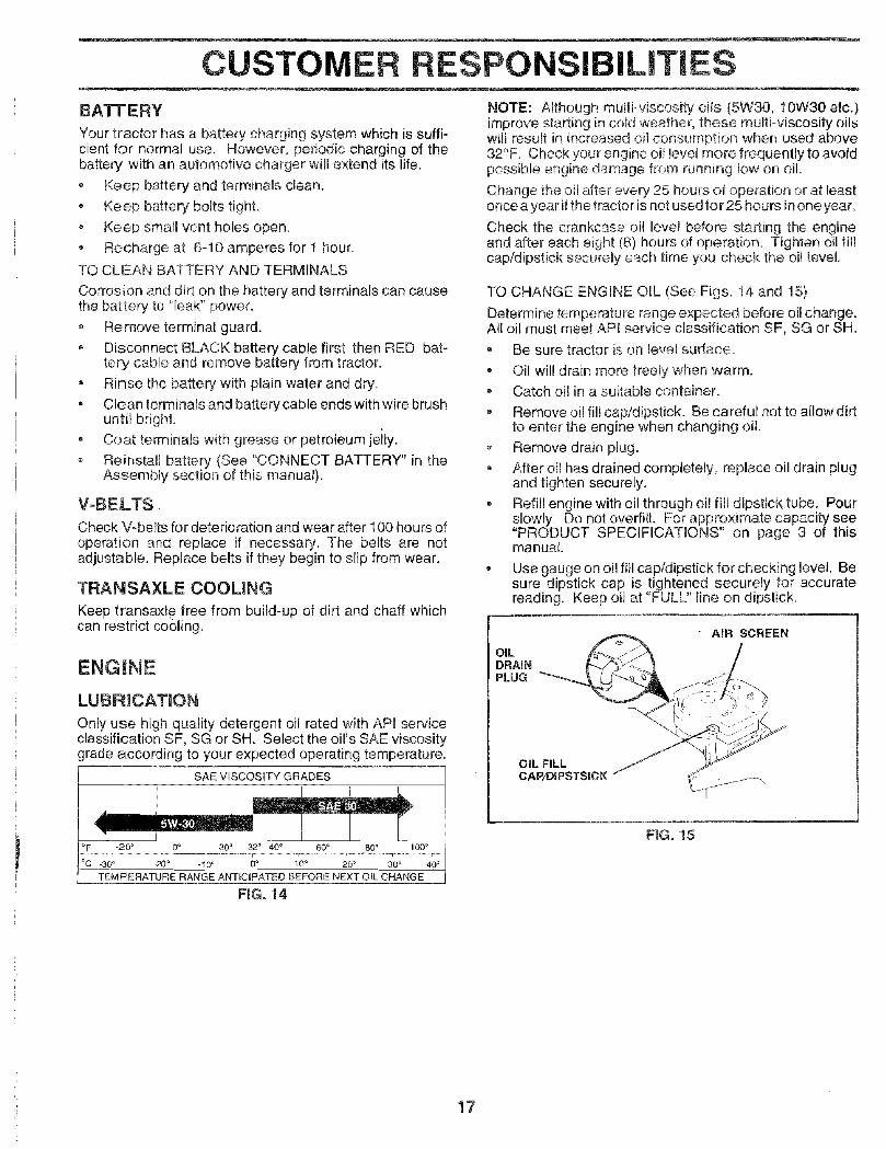
TO CHANGE ENGINE OIL (See Figs. 14 and 15)
Determine temperature range expected before oil change.All oil must meet APt service classification SF, SG or SH.
, Be sure tractor is on level surface.
• Oil will drain more freely when warm.- Catch oil in a suitable container.
, Remove oi! fill cap/dipstick. Be careful not to allow dirtto enter the engine when changing oil.
Remove drain plugoAfter oil has drained completely, replace oil drain plugand tighten securely.
o Refill engine with oil through oi! fitl dipstick tube. Pourslowly. Do not overfill. For approximate capacity see"PRODUCT SPECIFICATIONS" on page 3 of thismanual.
• Use gauge on oil fill cap/dipstick for checking level. Besure dipstick cap is tightened securely for accuratereading. Keep oil at "FULL" line on dipstick.
OILDRAINPLUG
OIL FILLCAP/DIPSTSICK
FiG. 15
17

CUSTOMER RESPONSIBILITIES
AIR FILTER (See Fig. 16)
Your engine wil] not mn _roper_y using a dirty air fiker.Clean the foam pre-cleaner after every 25 hours of opera°tion or every season, Sewice paper cad.ridge every 100hours of operation or every season, whichever occurs first.
Service air cleaner more often under dusty conditions.
• Remove knob(s) and cover,TO SERVICE PRE-CLEANER
, Slide foam pre-clear_er off cartridge,
Wash it in Tiquid deterg)n_ and water.
, Squeeze it dry in a ciean cloth
, Saturate it in engine oil. Wrap it in clean, absorbentcloth and squeeze to remove excess oil.
• If verj dirty or damaged, replace pre-cleaner.
o Reinstall pre-cleaner over cartridge., Reinstall cover and secure with knob(s).TO SERVICE CARTRIDGE
, Remove wing nuts and cartridge plate.
, Carefully remove cartridge to prevent debris from en-tering carburetor.
Clean cartridge by tapping gently on flat surface, tfverydirty or damaged, replace cartr dge
• Reinstall cartridge plate, wing nuts, precleaner, coverand secure with knob(s).
IMPORTANT: PETROLEUM SOLVENTS, SUCH ASKEROSENE, ARE NOT TO BE USED TO CLEAN THECARTRIDGE. THEY MAY CAUSE DETERiORATiON OFTHE CARTRIDGE. DO NOT OIL. CARTRIDGE, DO NOTUSE PRESSURIZED AIR TO CLEAN OR DRYCARTRIDGE,
WING NUT
CARTRIDGE
<__ PLATE
FOAMPRE-CLEANER
AiR SCREEN3ARTRIDGE
CLEAN AIR SCREEN (See Fig. 17)Air screen must be kept free of dirt and chaff to preventengine damage from overhoating. Clean with a wire brushor compressed air to remove dirt and stubborn dried gumfibers.
ENGINE COOLING FINS (See Fig. i7)Remove any dust, dirt or oil from engine cooling fins toprevent engine damage from overheating. Air guide coversmust be removed. Remove side panels and hood (See "TOREMOVE HOOD AND GRILL ASSEMBLY" in the Serviceand Adjustments section of this manual).
AIR GUIDE COVER (BOTH SIDES)
FIG. 17
FKG.16
18

CUSTOMER RESPO ILITIES
MUFFLER
inspect and replace corroded muffler and spark arrester (ifequipped) as it could create a fire hazard and/or damage.
SPAR K PLUGS
Replace spark plugs at the beginning of each mowingseason or after eveR' 100 hours of operation, whicheveroccurs first. Spark plug type and gap setting are shown in"PRODUCT SPECIFICATIONS" on page 3 of this manual.
'!
FFILTER _ --
CLAMP
IN-LIME FUEL FILTER (See Fig, 18)
The fuel filter should be replaced once each season. Iffuelfilter becomes ctogged, obstructing fuel flow to carburetor,replacement is required.
= With engine coo!, remove filter and plug fuel linesections.
, Place new fue! filter in position in fuel line with arrowpointing towards carburetor.
° Be sure there are no fuel line leaks and clamps areproperly positioned.
, Immediately wipe up any spilled gasoline.
NG. 18
CLEANINGo Clean engine, battery, seat, finish, etc. of all foreign
matter.
• Keep finished surfaces and wheels free of all gasoline,oil, etc.
Protect painted surfaces with automotive type wax.
We do not recommend using a garden hose to clean yourtractor unless the electrical system, muffler, air filter andcarburetor are covered to keep water out. Water in enginecan result in a shortened engine life.
19

_-- _ ii i = i,,i, ii !,,m. i= - --
SERVICE AND ADJUSTMENTS
CAUTION: BEFORE PERFORMING ANY SERVICE OR ADJUSTMENTS:
_ Depress cButcbJbrake pedal fully and set parking brake.= Place gearshift lever in neutral (N) position., Place attachment clutch in "DISENGAGED" position.
Turn ignition key "OFF" and remove key., Make sure the blades and all moving parts have compiete!y stepped., Disconnect spark plu 9 wire from spark plug and place wire where it cannot come in contact with
plug.- _ o_
TRACTOR
TO REMOVE MOWER (See Fig. 19)
Mower will be easier to remove from the right side of tractor.
Place at_achrnent clutch in "DISENGAGED" position.- Move attachment lift lever forward to {ower mower to its
lowest position.
* Rolr belt off engine pulley.
, Disconnect clutch rod from clutch lever by removingretainer spring.
, Disconnect anti-sway bar from chassis bracket byremoving retainer spring.
, Disconnect suspension arms from rear deck bracketsby removing retainer springs.
o Disconnect front links from deck by removing retainersprings,
, Raise lift lever to raise suspension arms. Slide mowerout from under tractor.
IMPORTANT: IF AN ATTACHMENT OTHER THAN THEMOWER IS TO BE MOUNTED TO THE TRACTOR,REMOVE THE FRONT LINKS,
TO INSTALL MOWER {See Fig= 19)
Raise attachment lift lever to its highest position.
• Slide mower under tractor with discharge guard to rightside of tractor.
Lower lift lever to its lowest position,install mower in reverse order of removal instructions.
CLUTCH
LEVER
RETAINERSPRING
SUSPENS!ON PULLEY
RETAINERSPRING
1ANTI=SWAY BAR
RETAINERSPRINGS(BOTH SIDES)
FIG. 19
20

SERVICE AN ADJU ENTSTO LEVEL MOWER HOUSING
Adjust the mower while tractor is parked on level ground ordriveway. Make sure tires are properly inflated (See"PRODUCT SPECIFICATIONS" on page 3 of this manual).If fires are over or undednftated, you will not properly adjustyour mower.
SIDE-TO-SIDE ADJUSTMENT (See Figs. 20 and 21)
* Raise mower to its highest position.
- At the midpoint of both sides of mower, measure heightfrom bottom edge of mowerto ground. Distance "A" onboth sides of mower should be the same or within 1/4"of each other.
o If adjustment is necessary, make adjustment on oneside of mower only.
• To raise one side of mower, tighten lift link adjustmentnut on that side.
• To lower one side of mower, loosen lift link adjustmentnut on that side.
NOTE: E_achfull turn of adjustment nut will change mowerheight about 1/8".
Recheck measurements after adjusting.
BOTTOM EDGE BOTTOM EDGEOF MOWER TO OF MOWER TOGROUND GROUND
F_G. 20
_\ SUSPENSION\ ARM
LiFT LINKADJUSTMENT NUT
FIG. 21
FRONT-TO-BACK ADJUSTMENT (See Figs. 22 and 23)LMPORTANT: DECK MUST BE LEVEL SIDE-TO-SIDE. IFTHE FOLLOWING FRONT-TO-BACK ADJUSTMENT ISNECESSARY, BE SURE TO ADJUSTBOTH FRONT LINKSEQUALLY SO MOWER WILL STAY LEVEL SIDE-TO-SIDE,
To obtain the best cutting results, the mower housingshould be adjusted so that the front is approximately 1/8" to1/2" lower than the rear when the mower is in its highestposition.Check adjustment on right side of tractor. Measure dis-tance "D" direclly in front and behind the mandrel at bottomedge of mower housing as shown.
Before making any necessary adjustments, check thatboth front links are equal in length. Both links should beapproximately 10-3/8".
• If links are not equal in length, adjust one link to samelength as other tink.
• To lower front of mower loosen nut "E" on both frontlinks an equal number of turns.
• When distance "D" is 1/8" to 1/2" lower at front thanrear, tighten nuts "F" against trunnion on both frontlinks.
, To raise front of mower, loosen nut "F" from trunnion onboth front links. Tighten nul "E" on both front links anequal number of turns.
, When distance "D" is 1/[_" to 1/2" lower at front thanrear, tighten nut"F"against trunnion on both front links.Recheck side4o-side adiustment..
NUT
FRONT LINKS TRUNNION
21 FiG. 23
I
E

SERVICE AND ADJUSTMENTS
TO REPLACE MOWER BLADE DRIVE BELT
(See Fig. 24)The mower blade drive belt may be replaced without tools.Park the tractor on level surface. Engege parking brake.
BELT REMOVAL -
° Remove mower from tractor (See "TO REMOVEMOWER" in this section of this manual).
• Work belt off b3th mandrel pulleys arid idler pulleys.
• Pull belt away from mower.
BELT INSTALLATION -
Install new belt in reverse order of removal.
, Make sure belt is in all pulley grooves and inside all beltguides
, Install mower in reverse order of removal instructions.
MANDREL IDLERPULLEY PULLEYS
MANDRELPULLEY
FIG. 24
WITH PARKING BRAKE "ENGAGED"
NUT "A""
JAM NUT
OPERATING ARM
FIGo 25
TO REPLACE MOTION DRIVE BELT(See Fig. 28)
Park the tractor on leve! surface. Engage parking brake.For assistance, there is a belt installation guide decal onbottom side of left footrest.
- Remove mower (See "TO REMOVE MOWER" in thissection of this manual.)
= Remove upper belt keeper,
Remove belt from stationary idler and clutching idler.Pull belt slack toward rear of tractor. Remove beltupwards from transaxle pulley by deflecting belt keep-ers.
, Pull belt toward front of tractor and remove downwardsfrom around engine pulley.
• Install new belt by reversing above procedure.IMPORTANT: MAKE SURE UPPER BELT KEEPER ISPOSITIONED PROPERLY BETWEEN LOCATOR TAB.
TO ADJUST BRAKE (See Fig. 25)
Your tractor is equipped with an adjustable brake systemwhich is mounted on the right side of the transaxle.
If tractor requires more than six (6) feet stopping distanceat high speed in highest gear, then brake must be adjusted.
- Depress clutch/brake pedal and engage parking brake.
= Measure distance between brake operating arm andnut "A" on brake rod.
If distance is other than 1-1/2", loosen jam nut and turnnut "A" until distance becomes 1-1/2". Retighten jamnut against nut "A".
Road test tractor for proper stopping distance as statedabove. Readjust if necessary. If stopping distance isstill greater than six (6) feet in highest gear, furthermaintenance is necessary. Contact your nearest au-thorized service center/department.
PULLEY
CLUTCHNGiDLER
iDLER
PULLEY
TABS
_UPPER BELTKEEPER
FiG. 2622

SERVICE AND ADJUSTMENTS
TRANSAXLE SHIFTER LINKAGE AND AD-JUSTMENT (See Figs. 27 and 28)
The transaxle should be in neutral when the gear shift leveris in the neutral (N) (lock gate) position. The adjustment ispreset at the factory; however, if adjustment is needed,proceed as tollows:
• Make sure transaxle is in neutral (N).Loosen two Iocknuts on tie rod.
Turn center rod until gearshift lever falls into neutrallock gate on fender console.
Tighten Iocknuts securely.
LEVER
LOCK GATE
FiG, 27
LOCKNUTS
CENTER ROD
TRANSAXLE
FIG. 28
TO ADJUST STEERING WHEEL ALIGNMENT
If steering wheel crossbars are not horizontal (left to right)whenwheels are positioned straight forward, remove steer-ingwheel and reassemble per instructions in the Assemblysection of this manual.
FRONT WHEEL TOE-IN/CAMBER
The front wheel toe-in and camber are not adjustable onyour tractor° if damage has occurred to affect the frontwheel toe-in or camber, contact your nearest authorizedservice center/department.
TO REMOVE WHEEL FOR REPAIRS(See Fig, 29)
. Block up e.xla securely.
, Remove axle cover, retaining ring and washersto allowwheel removaI (rear wheel contains a square key oDonot lose).
• Repair tire and reassembleo
, OR rear wheels only: align grooves in rear wheel huband axle. Insert square key.
Replace washers and snap retaining ring securely inaxle groove.
Replace axle cover.
NOTE: To seal tire punctures and prevent flat tires due toslow leaks, tire sealant may be purchased from your localparts dealer. Tire sealant also prevents tire dry rot andcorrosion.
WASHERS
AXLE COVER SQUARE KEY <REARWHEEL ONLY)
FIG. 29
TO START ENGINE W_TH A WEAK BATTERY'See Fig. 30}
CAUTION: Lead-acid batteries gener-
ateexptesivegases. Keepsparks, flameand smoking materials away from bat-teries. Always wear eye protectionwhen around batteries.
If your battery is too weak to start the engine, it should berecharged. If "jumper cables",are used for emergencystarting, follow this procedure:
IMPORTANT: YOUR TRACTOR iS EQUIPPED WITH A 12VOLT NEGATIVE GROUNDED SYSTEM. THE OTHERVEHICLE MUST ALSO BE A 12 VOLT NEGATIVEGROUNDED SYSTEM. DO NOT USE YOUR TRACTORBATTERY TO START OTHER VEHICLES.
o
TO
23"
TO ATTACH JUMPER CABLES o• Connect each end of the RED cable to the POSiTiVE
(+) terminal of each battery, taking care not to shortagainst chassis.Connect one end of the BLACK cable to the NEGA-TIVE (-) terminal of fully charged battery.
Connect the other end of the BLACK cable to goodCHASSIS GROUND, away from fuei tank and battery.
REMOVE CABLES, REVERSE ORDER -
BLACK cable first from chassis and then from the fullycharged battery.RED cable last from both batteries.

VICE ADJUSTMENTS
FiG. 30
TO REPLACE HEADLIGHT BULB• Raise hood.
• Pull bulb holder out of the hole in the backside of thegrill.
, Replace bulb il! holder and push bulb holder securelyback into the hole tn the backside of the grill.
, Close hood.
iNTERLOCKS AND RELAYS
Loose or damaged wiring may cause your tractor to runpoorly, stop running, or prevent it from starting.
• Check wiring. See electrical wiring diagram in theRepair Parts section of this manual.
TO REPLACE FUSE
Replace with 30 amp automotive-type plug-in fuse. Thefuse holder is located behind the dash.
TO REMOVE HOOD AND GRILL ASSEMBLY(See Fig. 31)• Raise hood.
• Unsnap headlight wire connector.
, Stand in front of tractor. Grasp hood at sides, tilt towardengine and lift off of tractor.
• To replace, reverse above procedures.
ENGINE
TO ADJUST THROTTLE CONTROL CABLE(See Fig. 32)
The throttte controt has been _resat at the factory andadjustment should not be necessary. Check adjustment asdescribed be!ow before loosening cable. If adjustment isnecessa_', proceed as follows:
With ei_g!r_eno_running, move fllrottle centre! !ever tofast position.
, Check that swivel is against side of quarter circle. If itis not, loosen cab!e clamp screw and pull caD/e backuntil swivel is against quarter circle. Tighten cableclamp screw securely.
TO ADJUST CHOKE CONTROL (See Fig. 33)
The cl_oke control has been preset at the factory andadjustment should not be necessary', Chock adjustment asdescribed below before loosening cab!e, if adjustment isnecessary,, proceed as follows:
• With engine not running, move choke control (locatedon dash panel) to full choke position.
• Remove air cleaner cover, filter and cartridge plate toexpose carburetor choke (see "AIR FILTER" in theCustomer Responsibilities section of this manual).
• Choke should be closed. If it is not, loosen casingciamp screw and move choke cable until choke iscompletely closed. Tighten casing clamp screw se-curely.Reassemble air cleaner.
CLAMP SCREW __
QUARTERCIRCLE
SWIVEL
FIG. 32
HOOD
\\
HEADLIGHTWIRECONNECTOR
\- /
, }
I '
CASING / :_J_'_.q__ /
CLAMP _ --,scREw ,
FIG. 33FiG. 31 24

SERVICE AN ADJUSTMENTS
TO ADJUST CARBURETOR (See Figs. 34 &35)The carburetor has been preset at the factory and adjust-ment should not be necessary. However, minor adjust-ment may be required to compensate for differences in fuel,temperature, altitude or [cad. If the carburetor does needadjustment, proceed as follows:
In general, turning the mixture screw in (clockwise) de-creases the supply of fuel to the engine giving a leaner fuel/air mixture. Turning the mixture screw out (counterclock-wise) increases the supply of fuel to the engine giving aricher fuel!air mixture
IMPORTANT: DAMAGE TO THE NEEDLES AND THESEATS IN CARBURETOR MAY RESULT IF SCREW ISTURNED IN TOO TIGHT.
PRELIIVHNARY SETTING -
• Be sure you have a clean air filter, and the throttlecontrot cable and choke are adjusted properly (seeabove).
® With engine off turn idle mixture screw in (clockwise)closing it finger tight and then turn out (counterclock-wise) 1-4/4 to 1-1/2 turns.
FINAL SETTING -
Start engine and allow to warm for five minutes. Makefinal adjustments with engine running and shift/motioncontrol lever in neutral (N) position.
- With throttle control lever in slow position, hold throttlelever against idle speed screw and adjust idle speedscrew to obtain !200 to 1400 RPM.
o While still holding throttle lever against idle speedscrew, turn idle mixture screw in (clockwise) untilengine begins to die and then turn out (counterclock-wise) until engine runs rough. Turn screw to a paintmidway between those two positions.
= Continue to hold throttle lever against idle speed screwand adjust idle speed screw to obtain 900 to 1200 RPM.Release throttle lever.
ACCELERATION TEST -
Move throttle control lever from slow to fast position. Ifengine hesitates or dies, turn idle mixture screw out(counterclockwise) 1/8 turn. Repeat test and continueto adjust, if necessary, until engine acceleratessmoothly.
High speed stop is factory adjusted. Do not adjust -damage may result.
tI_PORTANT: NEVER TAMPER W_TH THE ENGINEGOVERNOR, WHICH IS FACTORY SET FOR PROPERENGINE SPEED. OVERSPEEDING-THE ENGINEABOVETHE FACTORY HIGH SPEED SETTING CAN BEDANGEROUS. IF YOU THtNKTHE ENGiNE-GOVERNEDHIGH SPEED NEEDS ADJUSTING, CONTACT YOURNEAREST AUTHORIZED SERVICE CENTER/DEPARTMENT WHICH HAS PROPER EQUIPMENT ANDEXPERIENCE TO MAKE ANY NECESSARYADJUSTMENTS.
_DLE SPEEDSCREW
IDLE M_XTURESCREW
THROTTLELEVER
FIG. 34
IDLE SPEED (_-_
LEVERmDLE M_XTURESCREW
F_Go35
25

STORAGE
Immediately prepare your tractor for storage at the end ofthe season or if the tractor wil{ not be used for 30 days ormore,
,_ ,L _ inside a building_ w_achan openfRame_ or spark_ engine to cool
TRACTOR
Remove mower from tractor for winter storage. Whenmower is to be stored for a period of time, clean it thor-oughly, remove all dirt, grease, leaves, etc. Store in aclean, dry area.
= Clean entire tractor (See"CLEANING" inthe CustomerResponsibilities section of this manual).
, inspect and replace belts, if necessary (See belt re-placement instructions in the Service and Adjustmentssection of this manual).
* Lubricate as shown in the Customer Responsibilitiessection of this manual.
, Be sure that all nuts, bolts and screws are securelyfastened. Inspect moving parts for damage, breakageand wear. Replace if necessary.
• Touch up all rusted or chipped paint surfaces; sandlightly before painting.
BATTERY
= Fully charge the battery for storage.
• After a period of time in storage, battery may requirerecharging.
® To help prevent corrosion and power leakage duringlong periods of storage, battery cables should bedisconnected and batter/cleaned thoroughly (see "TOCLEAN BATTERY AND TERMINALS" in the Cus-tomer Responsibilities section of this manual).
After cleaning, leave cables disconnected and placecables where they cannot come in contact with batteryterminals.
Be sure battery drain tube is securely attached.
, If battery is removed from tractor for storage, do notstore battery directly on concrete or damp surfaces.
ENGINE
FUEL SYSTEMLMPORTANT: IT IS iMPORTANT TO PREVENT GUMDEPOSITS FROM FORMING IN ESSENTIAL FbELSYSTFM PARTS SUCH AS CARBURETOR, FUEL F{LTER,FUEL HOSE, OR TANK DURING STORAGE. ALSO,EX!_ERIENCE ;NDICATES CHAT ALCOHOL BLENDEDFUELS (CALLED GASOHOL OR USING ETHANOL ORMETHANOL) CAN ATTRACT MOISTURE WHICH LEADSTO SEPARATION AND FORMATION OF ACIDS DURINGSTORAGE, ACIDIC GAS CAN DAMAGE THE FUELSYSTEM OF AN ENGINE WHILE IN STORAGE.
, Drain the fuel tank.
• Start the enoine and let it run until the fue! lines andcarburetor are empty.
Never use engine orcarbur_tor cleaner products in thefuji tank or permanent damage may occur.
® Use fresh fuel next season.
NOTE: Fuel stabilizer is an acceptable aiternat,ve inmlntm_z_ngthe formation of fuel gum deposits during stor-age, Add stabilizer to gasoline in fue! tank or storagecontainer. Always follow the mix ratio found on stabilizercontainer. Run engine at least 10 minutes after addingstabilizer to allow the stabilizer to reach the carburetor, Donot drain the gas tank and carburetor if using fuel stabilizer.
ENGmNE OiL
Drain oil (with engine warm) and replace with clean engineoil, (Sea "ENGINE" in the Customer Responsibilitiessection of this manual).
CYUNDERS
Remove spark plug(s).
Pour one ounce of oil through spark plug hole(s) intocylinder(s).
o Turn ignition key to"START" position fora few secondsto distribute oil.
• Replace with new spark plug(s).
OTHER• Do not store gasoline from one season to another,
, Replace your gasoline can if your can starts to rust.Rust and/or dirt in your gasoline wil! cause problems,
o If possible, store your tractor indoors and cover it togive protection from dust and dirt.
, Cover your tractor with a suitable protective cover thatdoes not retain moisture. Do not use plastic. Plasticcannot breathe which allows condensation to form andwill cause your tractor to rust.
IMPORTANT: NEVER COVER TRACTOR WHILE ENGINEAND EXHAUST AREAS ARE ST_LL WARM.
26

TROUBLESHOOTING POINTS
PROBLEM
Will not start
Hard to start
Engine will not turn over
Engine clicks but will notstart
Loss of power
Excessive vibration
CAUSE
1. Out of fue!.
2. Engine net"CHOKED" properly.3. Engine flooded.4. Bad spark plug.5. Dirty air filter.6. Dirty fuel filter.7. Water in fuel
B. Loose or damaged wiring.9. Carburetor out of adjustment.
10. Engine valves out of adjustment.
1. Dirty air filter.2. Bad spark plug.3. Weak or dead battery.4. Dirty fuel filter.5. Stale or dirty fuel,6. Loose or damaged wirirlg.7. Carburetor out of adjustment.
CORRECTION
8. Engine vaives outof adjustment.
1. Fil! fuel tank.
2, See "TO START ENGINE" in Operation section.3. Wait several minutes before attempting to start.4. Replace spark plug.5. Cleantreplace air filter.6. Replace fuel filter.7. Drain fuel tank and carburetor, refill tank with fresh
gasoline and replace fuel filter.8. Check all wiring.9. See "To Adjust Carburetor' in Service Adjustments
section.
10. Contact an authorized service center/department.
1. Clutch/brake pedal not depressed.2. Attachment clutch is engaged.3. Weak or dead battery.4. Blown fuse.
5. Corroded battery terminals.6. Loose or damaged wiring.7. Faulty ignition switch.8. Faulty solenoid or starter.9. Faulty operator presence switch(es).
1. Weak or dead battery.2. Corroded battery terminals.3, Loose or damaged wiring.4. Faulty solenoid or starter.
1. Clean/replace air filter.2. Replace spark plug.3. Recharge or replace battery.4. Replace fuel filter.5. Drain fuel tank and refill with fresh gasoline.6. Check all wiring.7. See"To Adjust CarburetoK' in Service Adjustments
section.
8. Contact an authorized service center/department.
1. Cutting too much grass/too fast.2. Throttle in "CHOKE" position.3. Build-up of grass, leaves and trash under mower.4. Dirty air filter.5. Low oil levelidirtyoil.6. Faulty spark plug.7. Dirty fue! filter.8, Stale or dirty fuel.9. Water in fuel.
10. Spark plug wire loose.11. Dirty engine air screenffins.12. Dirty/clogged muffler.13. Loose or damaged wiring.14. Carburetor out of adjustment.
1. Depress clutch/brake pedal.2. Disengage attachment clutch.3. Recharge or replace battery.4. Replace fuse.5. Clean battery terminals.6. Check all wiring.7. Check/replace ignition switch.8. Check/replace solenoid or starter.9. Contact an authorized sexvice center/department,
1. Recharge or replace battery.2. Clean batten/terminals.3. Check el! wiring.4. Check/replace solenoid or starter.
1. Set in "Higher Cut" position/reduce speed.2. Adjust throttle control.3. Clean underside of mower housing.
15. Engine valves out of adjustment.
1. Worn, bent or loose blade.2. Bent blade mandrel.
3. Loose/damaged part(e).
4. Clean/replace air filter.5. Check oil level/change oil.6. Clean and regap or change spark plug.7. Replace fuel filter.8. Drain fuel tank and refill with fresh gasoline.9. Drain fuel tank and carburetor, refill tank with fresh
gasoline and replace fuel filter.10. Connect and tighten spark plug wire.11. Clean engine air screen/fins.12. Clean/replace muffler.13. Check all wiring.14. See "To Adjust Carburetor" in Service Adjustments
section.15. Contact an authorized service center/department.
1. Replace blade. Tighten blade bolt.2. Replace blade mandrel.3. Tighten loose part(s). Replace damaged parts.
27

TROUBLESHOOTi POINTS
PROBLEM
H . ,
Engine continuesto runwhen operatorle_ws seatwith a_aohmentciutch
engaged
Poorcut-uneven
Mower blades wig notrotate
Poor grass discharge
Headlight(s) not working(if so equipped)
Battery will not charge
Engine "backfires"when turning engine"OFF"
CAUSE
1. Fealty op_rator-safety presence control system
1. Worn. bsntor loose blade.2. Mower deck not level,
3, Buildup of grass, leaves, and trash undor mower.4, Bent blade mandrel.
5. Clogged mower deck vent holes from buildup ofgrass, leaves, and trash around mandr_ls,
1. Obstruction in clutch mechanism,2, Worn/damaged mower drive belt.3, Frozen idler pulley.4. Frozen blade mandref,
1, Engine speed too slow.2. qravei speed too fast.3. Wet grass.4. Mower deck not level.
5. Low/uneven tire air pressure,6, Worn, bent or loose olade.7. Buildup of grass, !_aves and trash under mower.8. Mower drive belt worn.9. Blades improperly installed
10, Impro0er blades used.1. Clogged mower deck vent holes from buildup of
grass, leaves, and trash around mandrels.
1 Switch is "OFF".
2, Bulb(s) burned out3. Faulty light switch.4. Loose or damaged wiring.5. Blown fuse.
1. Bad battery cell(s).2. Poor cable connections.
3. Faulty regulator (if so equipped).4. Faulty alternator.
1. Engine throttle control not set at "SLOW"position for 30 seconds before stopping engine.
CORRECTUON
1. Chect wiring, ;witches ar,d connectJor_s. _f notcorrected, car;loci an authorized service cent(÷r,rdepartment,
1. Replace blade. Tighten blade bolt.2, Leveimower deck.
3, C,leart underside o mower housing.4. Replace _lade mandrel5. Cean around mandrels to open vent holes.
1. Remove obstruction.2, Replace mower drive b.Jt,3. Replace idler pulley.4. Replece blade mandrei.
1. Place throttle control in "FAST" position.2. Shift to slower speed.3. Allow grass to dry before mowing.4, Level m_:w_r deck
5. Check tires for proper air pressure.6. Repiace/sharpen blade, Tighten blade bolt.7. Clean underside rff mower housing,8. Replace mower drive belt.9. Reinstall blades sharp edge down.
!0. Replace with blades listed in this manual.11. Clean around mandrels to open vent holes.
1. Turn switch"ON".
2. Repiac,; bulb(s).3, Check/replace light switch.4. Check widng and connections,5. Replace fuse.
1. Replace battery.2. ChecWclean all connections,3. Replace regulator.4. Replace alternator.
1. Move throttle control to "SLOW" position and allowto idle for 30 seconds before stopping engine.
28

TRACTOR - - MODEL NUMBER 917.259565
SCHEMATIC
RED "tl "oll oBATTERY
BIJ_C K
AMMETER(OPTIONAL)
_,1 --- I
.... t _
F-j SOLENOID
L WHITE
'z [/ IGNITION
FUSE 30 AMP.r___ Jc .....
I --i--- I
WH,TE '--_ O "
SWITCH03
/
iGNITiON SWITCH
o_ cl.CUiT! "MAKE"
_ RuN_4_#+_L_j _0NESTART B + L + S NONEL START [ +L+S_
........ J
CLUTCH / BRAKE(PEDAL UP)
BLACK
HOUR bMETER
(OPTIONAL)
RED
STARTER
BUICK
SEAT SWITCH
(NOT OCCUPIED)......... I
-2-1.........WHITE I f,_._ ! f'_ _.____ I ..... 1
, .......L____: .....
:::_'-'_ ATT MENT CLUTCH q, ..........GROUNDING €1"'
(CLUTCH OFF) 1 CONNECTOR |
O
BLACK _-i IGNITIONUNIT
CHARGING SYSTEM OUTPUT3AMP DC @ 3600 RPM
TWIN CYL ENGINES)28 'dOLTS AC MIN, @ 3600 RPM(CHARGtNG SYSTEM DISCONNECTED)
BLUE
LIGHTING SYSTEM OUTPUT DIODE _ALTERNATORORANGE 5 AM_AC @ 3600 F]PM _ 4-.-
14 VOLTS AC MIN. @ 3600 RPM (LIGHTS OFF)
HEADLIGHTS IBROWN BLACK
YOUR TRACTOR IS L----_O C_-_ IEQUIPPED WITH A SPECIAL "-._ (ALTERNATOR SYSTEM.THE LIGHTS ARE NOT _ -- ---(_)---- (CONNECTED TO THE NON-REMOVABLE REMOVABLE _J_BATTERY, BUT HAVE THEIR CONNECTIONS CONNECTIONS ///OWN ELECTRICAL SOURCE.BECAUSE OF THIS, THEBRIGHTNESS OF THE LIGHTS WIRING INSULATED CLIPSWILL CHANGE WITH ENGINE NOTE: IF WIRING INSULATEDSPEED. AT IDLE THE LIGHTS CLIPS WERE REMOVED FORWILL DIM. AS THE ENGINE IS SERVICING OF UNIT, THEYSPEEDED UP, THE LIGHTS SHOULD BE REPLACED TOWILL BECOME THEIR BRIGHTEST. PROPERLY SECURE YOUR WIRING.
29

REPAIR PARTSTRACTOR - - MODEL NUMBER 917.259565
ELECTRICAL
\
I
/

REPAIR PARTSTRACTOR - = MODEL NUMBER 917.259565
ELECTRICAL
KEY PARTNO. NO. DESCRiPTiON
1 1449262 747604123 STD5510254 STD5511256 STD5410257 7697J8 7603J9 109596X
10 14521111 15010912 14576916 15366419 STD55112520 7335040021 14743022 4152J24 4799J25 14614826 108824X28 14549129 121305X3O 1403O131 124211X32 14122633 10931gx40 15644241 7111040842 13156343 14567344 7364040045 121433X52 14194055 1749050870 140413
BatteryBolt, Hex 1/4-20 x 3/4Washer 9/32 x 5/8 x 16 GaugeWasher, Lock 1/4Nut, Hex 1/4-20TubeTray, BatteryClamp, HoseBolt, Btr Front !/4-20 x 7-1/2Holddown Battery Front MountNut, Push Nylon Battery Front 1/4Switch interlock Push-InWasher, Lock 1/4Nut, Hex, Jam 1/4-20Harness, Light Socket (w/4152J)Light BulbCable, BatteryCable, BatteryFuseCable, GroundSwitch, SeatSwitch, Ignition 4 PositionNut, IgnitionCover, Ignition SwitchKey, Molded, CraftsmanHarness, IgnitionBolt Blk Fin Hex 1/4-20 UNC x 1/2Cover, TerminalSolenoidNut Keps BIk Hex 1/4-20 UNCAmmeter Rectangular 6 AmpProtection Wire Loop (Hour Meter)Screw Thdro! 5/16-18 x 1/2Harness Engine B&SFrec Dual
NOTE: All component dimensions given in U.S. inches1 inch = 25.4 mm
31

REPAIR PARTSTRACTOR = = MODEL NUMBER 917.259565
CHASSIS AND ENCLOSURES
\
29
58
28
12
14
31
37
53
5557
6O
743 /
3 14
\ 38 ---.._.3
32

REPAIR PARTSTRACTOR - - MODEL NUMBER 917,259565
CHASSIS AND ENCLOSURES
KEY PARTNO. NO. DESCRnPTION
1 1595272 1403563 174906124 STD55!0255 1552729 150156X011
10 STD53371011 15592712 14566013 15593614 1749060817 144983X55818 126938X20 15643723 124028X25 1913131226 STD54143728 145198X55829 15521730 151287X55831 13997637 1749050838 13988639 13988751 7380040052 1909141653 14520154 1703O81455 14520257 STD55250758 1405476O 7214O6O664 15479871 7368040074 STD541437122 !57301123 152927140 158418142 156095143 154966144 1542O7145 156524147 74760412
ChassisDrawbarScrew, Thd., Roll. 3/8-16 x 3/4 Type TTWasher 13/32 x 3/4 x 16 GaugeBumper Hood/DashDash, SilkscreenedBolt, Carriage 3/6-16 x 1Panel, Dash, LHClip Tinnerman Grille P/LPanel, Dash, RHScrew, Thd., Roll. 3/8-16 x 1/2 Type TTHood AssemblyBumber HoodPlate Mtg Battery Fuel TankBushing, Snap, Nylon, Fuel LineWasher 13/32 x 13/16 x 12 GaugeLocknut, Hex, with Insert 3/8-!6 UNCGrille, W!Clips MS-558Lens, GrilleFender/FootrestBracket, Fender/SupportScrew, Thdrol. 5/16-18 x 1/2 TYTPivot Bracket Assembly, LH, Mower, RearPivot Bracket Assembly, RH, Mower, RearNut Lock W/Insert I/4 - 20 UNCWasher 9/32 X 7/8 X 16 Ga.Bracket Grille Pickoff LHScrew, Hex Head, Spiderlock #8 x 7/8 ABBracket Grille Pickoff RHBolt FinHex 1/4 -20 UNC X.75Air Duct P!L 18HP B&S Opp. TwinBolt Rdhd Sqnk 3/8-16 UNC x 3/4Dash Lower STLTNut Crownlock 1/4-20 UNCNut Crownlock 3/8-16 UNCBracket Shift STLTScrewBracket Suspension FrontPlate Reinforcement STLTBackrest Swaybar ChassisBracket Footrest STLTRod Pivot Chassis/HoodBolt Hex Hd 1/4o20 UNC x 3/4
NOTE: All component dimensions given in U.S. inches1 inch = 25.4 mm
33

REPAIR PARTS
TRACTOR = = MODEL NUMBER 917.259565DRIVE
88 8786
81
84
18 585
5
18
62
6
3536 /:
34
37
' 26l®/ 51
49_-- _
51,.-_
7527
53
34

REPAIR
DRIVE
PARTSTRACTOR ,. - MODEL NUMBER 917,259565
KEY PARTNO. NO.
2 1466823 123666X4 120000285 121520X6 174905128 154792
10 STD56121011 10570lX13 7455041214 STD55112515 7449054418 STD52371019 STD54143721 106933X22 13080424 STD54123725 106888X26 STD551 O3727 STD56121028 14520429 124236X30 13080731 127275X32 STD52310734 !5507135 120183X36 STD55106237 STD57181038 123674X39 STD52372740 4470J41 15477742 1913131247 12778348 15460449 !23205X50 STD52371551 STD541437
KEY PARTDESCRIPTION NO. NO, DESCRIPTION
Transaxle (See Breakdown) 52 STD54143tDana 430-114 53 1057!0XSpring, Return, Brake 55 105709XPulley, Transaxle 56 STD523712
Ring, Retainer 5; 160855127274XStrap, TorqueScrew, Thd., Roll. 5/16-18x 3/4 59 140312Rod Shifter Fender STLT 61 17490612Pin, Cotter 62 8883RWasher, Shift Plate 63 !40186Bolt 1/4-28 UNF W/Patch Grade 8 64 71170764WasherBolt, Hex Flghd 5/16-18 Grade 5 65 STD551143Bolt Fin Hex 3/8-16 UNC >_1. Gr 5 66 154778Nut 70 134683Knob 72 19132012Rod, Brake 74 109502XNut 75 121749XSpring, Brake Rod 76 STD581075Washer 77 123583XPin 78 121748XRod, Parking Brake 79 2228MCap, Parking Brake, Red 80 160783Bracket, Transaxle 81 156044Keeper, Belt, L.H. 82 123782XBolt 83 19171216Shaft Assembly, Foot Pedal 84 145643Bearing, Nylon 85 150360Washer 86 71208Roll Pin 87 19212016Pulley, Idler, Flat 88 12000008Boll 89 154886Spacer, Split .395x .59 90 124346XKeeper, Belt, Idler Fool-Proof 112 19091210Washer 13/32x 13/16 x12 Gauge 116 72110610Pulley, Idler, V-Groove, Plastic 118 154774Bellcrank Assembly 121 154419Retainer, BeltBoltNut Crown Lock 3/8-16 UNC
Nut Crown Lock 5/16-18 UNCLink, ClutchSpring, Clutch ReturnBolt Fin Hex 3/8-16 x 1-1 t4V-Belt, Ground DriveKeeper, Bell, R.H.Keeper, Belt, Center SpanScrew, Thd., Roll. 3/8-16 x 3/4Cover, PedalPutley, EngineBolt, Hex Head, Fin.7/16_20 x 4 Grade 5WasherKeeper, Belt, Engine, Fool-ProofGuide, Belt RH EngineWasher 13/32 x 1-1/4 x 12 GaugeSpacer, AxleWasher 25/32 x 1-1/4 x 16 GaugeE-RingKey, Square 2.0 x .1845t.1865Washer 25/32 x 1-5/8 x 16 GaugeKey Woodruff #9 3/16 x 3/4Arm, ShiftSfl.aft AssemblySpring, TorsionWasher 17/32 x 3/4 x .16 GaugeTie RodNut, NylockBushing, PivotWasherE-RingConsole, Shift, STLTNut, Self-Threading, Washer Hd 1/4Washer 9/32 x 3/4 x 10 GaugeBoll Rdhd Sqneck 3/8-16 x 1.25Spacer BellcrankNytiner Clutching STL
NOTE: Al! component dimensions given in U.S. inches1 inch = 25.4 mm
35

REPAIR PARTSTRACTOR - - MODEL NUMBER 917.259565
STEERING ASSEMBLY
!
62
i
• 36
44 i:d_
11
61
4O
\
\\ 53
\\./'/•
6788 70
43
36

REPAIR PARTSTRACTOR - ° MODEL NUMBER 917.259565
STEERING ASSEMBLY
KEY PARTNO. NO.
'i 1397682 1544273 1564834 t 5Y4735 6266H6 121748X7 192720!68 120000299 3366R
10 156438tl STD55!13713 15477915 7390100017 15654618 57079 .19 124035X20 !26684X22 7110O41O
23 12750125 15440626 126847X27 13687428 1913141629 1749061230 STD56121032 13046536 15509937 15292738 13976939 1913380840 STD54153741 100711L42 145O5443 12t749X44 15372046 !21232X47 6855M51 STD54143153 7368060054 7478052062 15659463 STD52371065 15478066 15440467 7478104468 15442969 16036770 74780636
DESCR|PT|ON
Steering WheelAxle Assembly STMP Dropped STLSpiadte Assembly, L.H.Spin]die Assembl_i, R.H.Bearing, Race, T,_rust, HardenedWasher 25/32 × 15/8 x 16 GaugeWasher 27/32 x 1-114 x 16 GaugeRing, KIipBearing, Steering ColumnDraglink Extended StampedWasher, Loci{_earing Axle STLT/GTNut, Lock, FIange 5/8-11 UNCShaft Assemb}y, SteeringWasher, Thrust .515 x .750 x .033S[_pport, ShaftWasher, Shim 1/4 x 5/8 × .062Screw, Hex Socket Head1/4-20 x 5/8Pittman Shaft AssemblyBracket, SteeringBushing, Link, DragGear, SectorWasher 13/32 x 7/8 x 16 GaugeScrew, Thd, Roll. 3/8-16 x 3/4PinRod, TieBushing, SteedngScrewInsert, Steering WheeiWasher 13/32 x 2-3/8 x 8 GaugeGripco NutAdaptor, Steering WheelBoot, Steering ShaftWasher 25/32 x 1ol/4 x 16 GaugeExtension Shaft Steering LR.LTCap, SpindleFitting, GreaseNut Lock Hex w!Ins. 5/16-18 UNCNut, Crown!ock 3/8-16 UNCBolt Fin Hex 5/16-18 UNC x 1-1/4Kit Steering Asm ServiceBolt, Fin Hex 3/8-16 UNC x 1 Gr 5Spacer AxleBearing Arm PittmanBolt, Fin Hex 5/8-11 UNC x 2-3/4Axle, BraceSpacer, Brace, AxleBolt, Fin, Hex 3/8-16 UNC x 2-1/4
NOTE: Ati component dimensions given in U.S. inches1 inch = 25.4 mm
37

REPAIR PARTSTRACTOR - - MODEL NUMBER 917.259565
SEAT ASSEMBLY
\\
\\
\\,
17 12
5
25
23
KEY PARTNO. NO,
1 1401232 1405513 747606164 191316105 1450066 STD5414377 124181X8 174906169 19131614
10 ,15592512 121246X
DESCRIPTION
SeatBracket Pnt Pivot Seat (blk)Bolt Fin Hex 3/8-16 UNC x 1Washer Fiat 13/32 x 1 x 10 GaCtip Push-inNut Lock Hex W!Ins 3/8 -16 UNCSpring Seat Cprsn 2 250 BIk ZiScrew 3/8-16xlWasher 13/32 x 1 x 14 GaPan Pnt Seat (blk)Bracket Pnt Mounting Switch
KEY PARTNO. NO.
13 121248X14 7205041115 13430016 121250X17 123976X21 15323622 STD54143123 7478081424 1917191225 127018X26 STD551150
DESCRIPTION
Bushing Snap BIk Nyl 50 IdBolt Rdhd Sht Nk 1/4-20xl-3/8Spacer Split 28 X 96 ZincSpring Cprsn 1 27 BIk PntNut Lock 1/4 Lge Fig Gr 5 ZincBolt Shoulder 5/16-18 UncNut Lock Hex W!Ins 5/16-18Bolt Fin Hex 1/2-13 X7/8 Gr 5Washer 17/32 X 1-3/16 X 12 GaBolt Shoulder 5/16-18 X 62Washer Lock HW HIcl Spr 1/2
NOTE: AII component dimensions given in U.S. inches1 inch = 25,4 mm
38

REPAIR PARTSTRACTOR - - MODEL NUMBER 917.259565
DECALS
17
22
19!4 !3 !4
15.
KEY PARTNO. NO.
1 1564392 2735033 1512994 1513006 1336447 1509279 146709
10 15033311 !5636813 146046
KEY PARTDESCRIPTION NO. NO.
Decal Fender Danger Sears 14 147139Decal, Engine 19.5 HP Turbo 15 160396Decal Hood Rh Craftsman 17 158215Decal Hood Lh Craftsman 19 138047Decal Maint Customer Sears Dora 20 156787Decal Panel Side B&S 22 149516Deca[ Fender Craftsman Gold - - 138311Decal Cap CNSMR Help Line SRS -- 154515Decal Fender STLT Oper Inst E/S - - 154516Decal V-belt Dr Sch - - 161406
- - 161407
DESCRIPTfON
Decal Chassis 42"Decal Mower Drive SchematicDecal Insert, HoodDecal Battery Diehard SearsDecal Deck'Mower EZ3 MulchingDecat BatteryDecal Lift HandlePad Footrest Lh STLTPad Footrest Rh STLTManual, Owner's (English)Manual, Owner's (Spanish)
4,10
11
39
KEY PARTNO. NO. DESCRIPTION
1 591922 651393 106222X4 59904
5 106732X4276 278H7 9040H8 106108X4279 122082X
10 7152J
11 104757X-- 144334
Valve Cap, TireStem, ValveTire, FrontTube, Front Tire(Not Provided, Service Item Only)Rim, Fron_Fitting, Grease (Front Wheel Only)Bearing, Flange (Front Wheel Only)Rim, RearTire, RearTube, Rear Tire(Not Provided, Service Item Only)Cap, AxleSea}ant, Tire (10 oz. Tube)
NOTE: All component dimensions given in U. B. inches1 inch = 25.4 mm

REPAIR PARTSTRACTOR - = MODEL NUMBER 917.259565
ENGINE
14
31
3940
37
1310
I
29
OPTIONAL EQUIPMENT
Spark Attester
4O

REPAIR PARTSTRACTOR - - MODEL NUMBER 917o259565
ENGINE
KEY PARTNO. NO. DESCRIPTION
1 1512732 17720410
.......
4 1497235 1440696 1440687 1381298 150176
10 14555211 STD55112512 STD52250713 272250'14 1328033615 1320030016 STD55123717 1749062423 15612325 14599626 7392060027 15292729 13718031 15710332 15597133 123487X34 106082X35 1749051237 8543R38 .......
39 !09227X40 3645J41 13927781 128861
Control Throt Paddle 32 22Screw Hex Thd Cut 114-20x5/8 TEngine (See Breakdown) BriggsModel No. 42E707-2631-E1Muffler ExhaustExhaust f_sm. LeftExhaust Asm. RightClamp Tube Double EngineBolt 5/16 - 18 UNC X 3/4 W/SeresHeat Shield LtWasher Lock Hvy. Helical 1/4Bolt Fin Hex 1/4-20 x 3/4Gasket MufflerNipple Pipe 4-1/2"Elbow Std 90 Degree 3/8-18 NptWasher Lock Ext Tooth 3/8Screw Thdrol 3/8-16x1-1/2 TyttShield BrowningControl ChokeNut Keps 3/8-24 UnfScrew T-l #10-32 x 5 x 3/8 FlangeArrestor SparkTank Fuel 3 50 RearCap Fuel Guage STLTClamp Hose BIkSpacer PadScrew Thdrol 5/16-18 x 3/4 TYTLine FuelPlug Oil Drain (Order From EngineManufacturer)Pad Idler 1.75 x .75 x .06BushingStem Tank FuelNut, Flange 1/4-20,Starter Nut
NOTE: All component dimensions given in U.Soinches1 inch = 25.4 mm
41

REPAIR PARTSTRACTOR - = MODEL NUMBER 917.259565
MOWER LIFT
28 27
25 2423
7
4
19
13
19
13
49
30
5O
3
fN
15
42

REPAIR PARTSTRACTOR = ° MODEL NUMBER 917o259565
MOWER LIFT
KEY PARTNO, NOo DESCRIPTION
1 159460 Wire Assy,, Inner, with Plunger2 159471 Shaft Asm. Lift3 105767X Pin Groove4 12000002 E Ring #5!33-625 19211621 Washer 21/32xl x21 Ga.8 120163X Bearing Nylon7 125631X Grip Handle Fluted8 122365X Button Plunger Read
11 139865 L}nk Lift Lh Fixed Length12 139866 Link Lift Rh Fixed Length13 STD624008 Retainer Spring!5 127218 Link Front16 73350800 Nut Jam Hex 1/2-13 Unc17 130171 Trunnion BIk Zinc18 73800800 Nut LockW/Wsh 1/2-13 Unc19 139868 Arm Suspension Rear20 STD624008 Retainer Spring23 110807X Nut Spring24 19131016 Washer 13/32 x 5/8 x 16 Ga.25 2876H Spring 2-1/8"26 76020308 Pin cotter 3/32 x !/227 126971X Rod Adj. Lift28 73350600 Nut Hex Jam 3/8-1629 138057 Knob Inf. 3/8-1630 150233 Trunnion Infin. Height31 140302 Bearing, Pivot, Lift, Special32 73540600 Nut, Crownlock 3/8-2449 145212 Nut Flange Lock50 110452X Nut Push
NOTE: All component dimensions given in U.S. inches1 inch = 25.4 mm
43

REPAIR PARTSTRACTOR - - MODEL NUMBER 917.259565
MOWER DECK
68
59
34
• 3332
105
17 '_104105 /_
106--
6
21
16
27
44

REPAIR PARTSTRACTOR - -.MODEL NUMBER 917.259565
MOWER DECK
KEY PART KEY PARTNO, NO. DESCRiPTiON NOo NO.
1 1443932 STD5331073 1380174 1384405 STD6240086 1308328 _508579 STD551137
10 14029611 13414912 12989513 137645
14 12877415 110485X16 14032917 7211061018 7214050519 13282720 13688821 STD54143122 13475323 13126724 105304X25 123713X26 110452X27 13096828 1911101629 13149130 15772231 12996332 15353533 13726634 STD53371735 13383536 13149437 191313164O STD54143741 13355143 14008344 14008845 STD62400346 13772948 13394449 15506650 13134051 STD54141052 13988853 131845X900
Mower HousingBoltBracket Assembly,Sway Bar, FrontBracket Assembly, Sway BarRetainer SpringArm, Suspension, RearBait, Hex 3/8-24 x 1.25 Grade 8Washer, LockWasher, HardenedBlade, MulchingBearing, BailShaft Asser'nbly, Mandrel, Venteddncludes Key Number 6)Housing, Mandre!, VentedBearing, Ball, MandrelSiripper, Vented Mower DeckBolt, Carriage 3/8-16 x 1-1/4Bolt, Carriage 5/16-18 x 5/8Bolt, ShoulderBaffle, VortexNut Crown!ock 5/16-18 UNCStiffener BracketBracket, DeflectorCap, SleeveSpdng, Torsion, DeflectorNut, PushShield, DeflectorWasher 11/32 x 5/8 × 16 GaugeRod, HingeScrew Thdrol Washer HeadWasher, SpacerPulley, MandrelNut, Top!ock, FlangedBoltFastner, Christmas TreePulley, Idler, FlatWasher 13/32 x 13/16 x 16 GaugeNut Crownlock 3/8-16 UNCRod, Pivot, with NibsRod, Clutch, Secondary, with NibsGuard, Mandrel, Loll.RetainerScrew, Thd. Roll 1/4-20 x 5/8Washer, HardenedRoller Assembly, Cam FollowerBolt, Shoulder #10-24 Grade 5LocknutBolt, Shoulder 5/16-18 UNCArm Assembly, Pad, Brake
DESC_|PTION
54 13394355 15504656 122052X58 14008659 14104367 14984668 14420071 14242772 13187073 12784774 121748X75 1200002976 12890377 12784578 15480979 12749880 15370181 7335060082 14202883 !20958X84 15608485 7214061892 STD541437101 136420102 71161010103 19061218104 STD551110105 130758106 2029J111 155197112 155198113 17490512114 73510600115 72110504116 137644117 133957118 73930600119 19121414121 143723128 153390129 19131312130 STD523710131 STD533710132 19132293-- 130794
145411
Washer, HardenedArm, idlerSpacer, RetainerSpring, Torsion BrakesGuard, TUV JdterKnob Custom OvalV-BeltRod, Clutch, Primary, with NibsSpring, ReturnArm, Clutch, SecondaryWasher 25/32 x 1-5/8 x 16 GaugeRing, KlipBoit, Shoulder 3/8-16 UNC x 1.44Keeper, SpringLever Asm. Clutch Pri PIm STLTBushing, Large, BrassSpring, Mower ClutchNut, Hex Jam 3/8-18 UncTrunnion, Adj.Washer, SinteredKeeper Belt idlerBolt RDHD Sq 3/8-18 UNC x 2-1/4NutMulcher CoverScrewWasher #10Washer, LockLatch Assembly, BaggerNut, WeldBracket, Gauge, Wheel L.H.Bracket, Gauge, Wheel R.H.Screw Thdrol 5/!6-18 x 3/4Nut, Hex, Keps 5/!6-18 UNCBolt, Carriage 5/!6 UNC x 1/2Bolt, ShoulderWheel, GaugeNut, Centerlock 3/8-16Washer 3/8 x 7/8 x 14 GaugeBracketWasher Felt ,Washer 13/32 x 13/16 x 12 Ga.Bolt, Fin Hex 3/8-16 UNC x I Gr. 5Bolt, RDHD SQNK 3/8-16 UNC x 1Washer 13/32 x 1-3/8 x 4 Ga.Mandrel Assembly (Includes KeyNumbers 8-10, 12-15, 31 and 32)Mower Deck, Complete (Standard
NOTE: All component dimensions given in U.S. inches1 inch = 25.4 mm
45

REPAmR PARTSTRACTOR = = MODEL NUMBER 917o259565
DANA TRANSAXLE o ?_ODEL NUMBER 4360ot 14
5253
54
_2
70
46

REPAIR PARTSTRACTOR = = MODEL NUMBER 917.259565
DANA TRANSAXL_ - MODEL NUMBER 4360-114
KEY PART KEY PARTNO. NO. DESCRiPTiON NO. NO. DESCRiPTiON
1 1609552 2274J3 1344004 i05904X5 1609406 1347887 108727X8 120951X9 !48266
10 2225J11 13479312 143697I3 120415X14 14267415 106846X16 106095X17 105909X18 !05910X19 14826920 16094321 13824622 13823823 14826824 14367325 2244J26 105916X27 120470X28 110070X29 14267730 14268131 124644X32 108980X33 120406X34 13479635 105925X36 2228J
Housin_ Upper 37 2231JScrew, lapping, 1/4-20 X .734 38 160944Bail, Detent 39 124639XSpring, Detent 40 120472XScrew, Tapping, No. 10-24 X .482 41 105928XAssy, Kit, Shifter 42 106605XV-Ring 43 "I34394Puck, Friction 44 120473XBearing, Flange 45 160942Ring, Retaining 46 142678Assy, Kit, Shim, .625 Shaft 47 124641XGear, Spur, 15T 48 106589XWasher, Plain, .632 X 1.38 X .046 49 120408XKey, Woodruff, No. 9 50 105937XAssy, Kit, Input Shaft 51 2226JPinion, Bevel, I4T 52 134401Ring, Retaining 53 2264JChain, 24 Pitches 54 160946Seal, Oil 55 160947Gear, Spur, 12T 56 160948C011ar,Clutch 57 110071XAssy, Kit, Clutch Keys 58 120952XBearing, Flange 59 160949Shaft, Intermediate 60 160950Key, Woodruff, No. 61 61 160951Ring, Retaining 62 120961XSprocket, 18T 63 7294JSpacer, 1.131X1.45X.494 64 108989XGear, Spur, 3TT 65 160952Gear, Spur, 35T 66 120954XGear, Spur, 30T 67 160953Gear, Spur, 25T 68 138244Gear, Spur, 22T 69 108996XGear, Spur, 19T 70 160954Washer, Plain, .640 X 1.37 X .061 71 73810500Washer, Plain, .632 X 1.00 X .046 72 120416X
Washer, Plain, .632 X 1.00 X .031Assy, Gear, Comb., 12T & 30TShaft, qdlerSpacer, .633 X .87 X .755Sprocket, 9TGear, Bevel, 42TAssy, Kit, Shim, .750 ShaftShaft, DriveCover, DetentGear, Spur, 12TGear, Spur, 20TGear, Spur, 25TGear, Spur, 28TGear, Spur, 31TWasher, Plain, .832 X 1.00 X .060Washer, NeopreneWasher, Plain, .758 X 1.25 X .031Axle, LHGear, Miter, 12T, SplinedRing, RetainingGear, Spur, 32TShaft, CrossGear, Miter, 12T, IdlerAxle, RHHousing, LowerPuck, FrictionDisc, BrakeSpacer, Brake PuckJaw, BrakePin, DowelScrew, Tapping, 5/16-18 X 2.35Lever, ActuatingWasher, Plain, .321 X 1.00 X .055Bracket, Anti-RotationNut, Lock, 5t16-24Grease
NOTE: All component dimensions given in U.S. inches1 inch = 25.4 mm
47

REPAIR PARTSTRACTOR - - MODEL NUMBER 917,259565
BRIGGS & STRATTOH ENGINE - MODEL NUMBER 42E707', TYPE NUMBER 2631=E1
868_ @40 35
36 _)33 34
219A_ 4s
12
601
240
523
842
422
284A
525
524 0
284
_t
534
?
643
535
445
235
642
537
161
48

REPAIR PARTSTRACTOR = o MODEL NUMBER 917.259565
BRIGGS & STRATTON ENGINE - MODEL NUMBER 42E707, TYPE NUMBER 2631-E1
103
435 "_,. 634 _,._
232
202
257
5452
4.68
1O05
332
Q 75
188
1oo6
_726 383
49

REPAIR PARTSTRACTOR = - MODEL NUMBER 917.259565
BRIGGS & $TRATTON ENGINE =MODEL NUMBER 42E707, TYPE NUMBER 2631=E1
653
783801
544
803
@ 592
201
209A 209
414 207 y
307
5O

REPAIR PARTSTRACTOR .. = MODEL NUMBER 917.259565
BRIGGS & STRATTON ENGINE _ MODEL NUMBER 42E707, TYPE NUMBER 2631=E1
8A_ 9
10A
10
304305
3 22
881
5A
13
t019 LABEL KIT]
REQUIRES SPECIAL TOOLSTO INSTALL. SEE REPAIRiNSTRUCTION MANUAL,
305
3O8
306
3O7 306A
308A307
3O5
51

REPAIR PARTSTRACTOR o - MODEL NUMBER 917.259565
BRIGGS & STRATTON ENGINE - MODEL NUMBER 42E707, TYPE NUMBER 2631 -El
KEY PART KEY PARTNO. NO. DESCRiPTiON NO. NO. DESCRIPTION
1 4970742 3992653 3910864 4933045 493457
5A 4934587 271867
7A 2718688 495754
8A 222892
9 2780310 94382IOA 9483011 28O22512 273208
271188271189
13 9456515 9423916 394028
9419619 39926420 29167522 9472423 49118024 22269825 498584
498585498586498587
26 394959394960394961394962
27 26312928 498319
39128629 394306
39715832 9467133 39042034 26152835 6590636 2682840 22159641 29226042 49455345 26136846 21448450 21329051 27141251A 28141252 _27088453 93970
Cylinder Assembly 54 93208Bushing 75 222511
* Seal, Oil 78 95039Sump, Engine 91 499281Head, Cylinder #1 95 93499Head, Cylinder #2 96 221939
* Gasket, Cylinder Head #1 97 499172* Gasket, Cylinder Head #2 98 91920
Breather Assembly #1 99 26157Cover, Breather Cylinder #2 102 271607(Used Only on Key #572, 103 298514Air Baffle with Holes for Mounting) 104 231435
* Gasket, Breather 105 394882Screw, Seres 107 499655Screw, Seres 108 225373Tube, Breather 109 392673
* Gasket, Crankcase, .015" Thick 116 280474* Gasket, Crankcase, .005" Thick 117 232018* Gasket, Crankcase, .009" Thick 232022
Screw, Cylinder HeadPlug, Oil Drain 119 94152Crankshaft 121 491539Timing Gear Key 125 19306Bushing 127 223472
* Seal, Oil 161 496599Screw, Seres 165 94289Ftywhee[ 187 299146Key, Flywheel 188 94627Piston Assembly, Standard Size 201 262683Piston Assembly, .010" Oversize 202 262684Piston Assembly, .020" Oversize 203 280997Piston Assembly, .030" Oversize 205 93971Ring Set, Standard Size 206 94298Ring Set, .010" Oversize 207 262337Ring Set, .020" Oversize 209 262352Ring Set, .030" Oversize 209A 261563Lock, Piston Pin 219 394348Pin, Piston, Standard Size 219A 393415Pin, Piston, .005" Oversize 220 222773Rod, Connecting, Standard Size 222 491282Rod, Connecting, .020" Undersize 224 94297Screw, Connecting RodValve, ExhaustValve, IntakeSpring, Valve, IntakeSpring, Valve, ExhaustRetainer, Valve, IntakeRetainer, Valve, ExhaustKeeper, ValveTappet, ValveGear, CamManifold, Intake
.... Gasket, Carburetor MountingSpacer, Carburetor
* Gasket, Intake Manifold MountingScrew, Hex Head,Carburetor to Manifold
Screw, PhillipsWasher, SpringScrew, HexBody Assembly, UpperScrew, SeresValve, ThrottleShaft, ThrottleScrew, Fillister HeadSpring, Throttle AdjustGasket, Carburetor BodyFloat, CarburetorPin, Float HingeValve, NeedleBody Assembly, LowerValve, ChokeShaft, ChokeO-RingJet. Needle Valve, FixedJet, Needle Valve, Fixed,High AltitudeScrew, Hex HeadCarburetor KitCarburetorPlug, WelchBase, Air CleanerNut, WingLine, Fuel, 28" Long (Cut to Suit)ScrewLinkLinkCrank, BellScrew, Hex HeadNutSpring, Control, RodSpring, GovernorSpring, Governor IdleGear, GovernorOil SlingerWasher, ThrustBracket, ControlScrew, Torx®
* included in Gasket Set (495868)
** Included in Carburetor Kit (491539)
*** Included in Carburetor Kit (491539),and Pump Repair Kit (393397)
.... Included in Gasket Set (495868),and Carburetor Kit (491539)
NOTE: All component dimensions given in U.S. inches1 inch = 25.4 mm
52

REPAIR PARTSTRACTOR - = MODEL NUMBER 917.259565
BRIGGS & STRATTON ENGINE - MODEL NUMBER 42E707, TYPE NUMBER 2631-E1
K!_Y PART KEY PARTNO° NO. DESCRIPTION NO. NO. DESCRiPTiON
227 491297 Lever Assembly, Governor 556 93585229 62199 Washer 562 93853230 223882 Washer, Governor Crank, Inside 567 9481!235 224995 Shield, Fuel Spray240 394358 Filter, Fuel 569 272645244 230318 Connector, Fuel Line 572 224816257 93897 Screw, Seres 573 491304284 94674 Screw, Hex Head 592 92278284A 94882 Screw, Hex Head 661 93053304 495469 Housing, Blower, Red 615 94296305 94786 Screw, Sems 615A 263080306 222846 Shield, Cylinder 616 491530306A 223734 Shield, Cylinder 634 271013307 94930 Screw, Self-Tapping 634A 491287308 224774 Cover, Air Guide 635 66538308A 224775 Cover, Air Guide 642 225008309 497596 Motor, Starter 643 496700310 94003 Bolt, Thru 653 93585311 497608 Brush Set 726 391362332 230674 Nut, Hex333 394891 Armature, Magneto 741 262989334 94731 Screw, Sems 783 280104337 802592 Plug, Spark 80! 394860356 494705 Wire, Stop 802 497607358 495868 Gasket Set 803 497604363 19203 Flywheel Puller 819 946/'5383 89838 Wrench, Spark Plug 842 270920391 280197 Body, Pump 847 495715392 261395 *** Spring, Diaphragm 85! 493880394 272638 *** Diaphragm, Carburetor 858 270989414 220680 Washer 859 271025422 222875 Bracket, Oil Fill 860 261358432 221377 *** Cap, Spring 861 393397434 223688 Cover, Diaphragm 868 497212435 93829 Screw, Diaphragm Cover 869 261463445 394019 Filter, Air 870 213316468 497908 Screen, Rotating 871 261961474 393474 Alternator 231218482 93621 Screw, 877 393456510 497606 Drive, Starter 881 495901523 494947 Cap, Oil Fill 955 397862524 271157 * Seal, Fill Tube 1005 281053525 495348 Tube, Oil Fill (includes Seals 1006 224901528 393815 Hose, Vacuum 1019 496726534 94823 Screw, Air Cleaner 1090 497605535 272490 Filter, Air537 271411 .... Gasket, Air Cleaner544 497603 Armature, Starter552 262332 Lower Bushing, Governor552A 262331 Upper Bushing, Governor
Screw, Hex HeadBolt, Governer LeverScrew, Hex Head,Back Plate to Cylinder
* Gasket, BaseBaffle, Air, Cylinder #2Plate, BackNut, Hex.Clamp, HoseRetainer, E_RingRetainerCrank, Governor
"* Washer, Throttle Shaft* Seal, Governor Shaft
Boot, Spark PlugCover, Air CleanerPlato, Air CIoanerScrew, Hex HeadGear, Ring(Includes Mounting Parts)Goar, Timing :..Goar, StarterCap, DriveCap, EndHousing, StarterScrew, Hex Head
* Seal, CapTube Assembly, OilTerminal, Cable
*** Diaphragm, Carburetor*** Gasket, Pump*** Spring, Diaphragm
Repair Kit, PumpSeal, ValveSeat, Valve, IntakeSeat, Valve, ExhaustBushing, Guide (Exhaust Only)Bushing, Guide (intake, Brass)Wire, AlternatorPlate, Cover 'Plug and Seal, SolenoidFan, FlywheelRetainer, FanLabel KitRetainer, Brush
* Included in Gasket Set (495868)
** included in Carburetor Kit (491539)
*** Included in Carburetor Kit (491539),and Pump Repair Kit (393397)
.... Included in Gasket Set (495868),and Carburetor Kit (491539)
NOTE: All component dimensions given in U.S. inches1 inch = 25.4 mm
53

SERVICE NOTES
54

SUGGESTED GUIDE FOR SiGHTiNG SLOPES FOR SAFE OPERATION
SIGHTING_UIDE
ONLY RiDE UP AND DOWN HILL,NOT ACROSS HiLL
SIGHT AND HOLD THIS LEVEL WiTHSKY LINE OR TREE.
t _ Operate your Tractor up and down the face of slopes (notgreater than 15°), never across the face. Make turns gradu-O ally to prevent tipping or loss of control. Exercise extreme
caution when changing direction on slopes.

OWNER'SMANUAL
MODEL NO.917.259565
IF YOU NEEDREPAIR SERVICE
OR PARTS:
FOR REPAIR SERVICE, CALLTHIS TOLL FREE NUMBER:
1-800-4-REPAIR(1-800-473-7247)
FOR REPLACEMENT PARTSINFORMATION AND
ORDERINGi'CALL THISTOLL FREE NUMBER:
1-800-FON-PART(1-800-366-7278)
FOR CONSUMER ASSISTANCEHOT LINE, CALL-I-HISTOLL FREE NUMBER:
1-800-659-5917
I:RrlFTZHrlN19.5 HPELECTRIC START42" MOWER6 SPEED TRANSAXLELAWN TRACTOR
Each tractor has its own model number. Each engine hasits own model number.
The model number for your tractor will be found on themodel plate located under the seat.
The model number for your engine will be found on theblower housing of the engine.
All parts listed herein may be ordered from any Sears,Roebuck and Co. Service Center/Department and most Re-tail Stores.
WHEN ORDERING REPAIR PARTS, ALWAYS GIVE THEFOLLOWING INFORMATION:
• PRODUCT- TRACTOR
• MODEL NUMBER - 917.259565• ENGINE MODEL NO. - 42E707-2631-E1
• PART NUMBER
• PART DESCRIPTION
Your Sears merchandise has added value when youconsider Sears has service units nationwide staffed withSears trained technicians.., professional techniciansspecifically trained to insure that we meet our pledge toyou, we service what we sell.
161406 07.11.97 KFSW Printed in U.S.A.