Model No. PFEL05815.1 USER’S MANUAL - Sweatband
32
CAUTION Read all precautions and instructions in this manual before using this equipment. Keep this manual for future reference. Model No. PFEL05815.1 Serial No. Write the serial number in the space above for reference. USER’S MANUAL Serial Number Decal CUSTOMER SERVICE UNITED KINGDOM Call: 0330 123 1045 From Ireland: 053 92 36102 Website: iconsupport.eu E-mail: [email protected] Write: ICON Health & Fitness, Ltd. Unit 4, Westgate Court Silkwood Park OSSETT WF5 9TT UNITED KINGDOM AUSTRALIA Call: 1800 993 770 E-mail: [email protected] Write: ICON Health & Fitness PO Box 635 WINSTON HILLS NSW 2153 AUSTRALIA iconeurope.com
Transcript of Model No. PFEL05815.1 USER’S MANUAL - Sweatband
CAUTIONRead all precautions and instructions in this manual before using this equipment. Keep this manual for future reference.
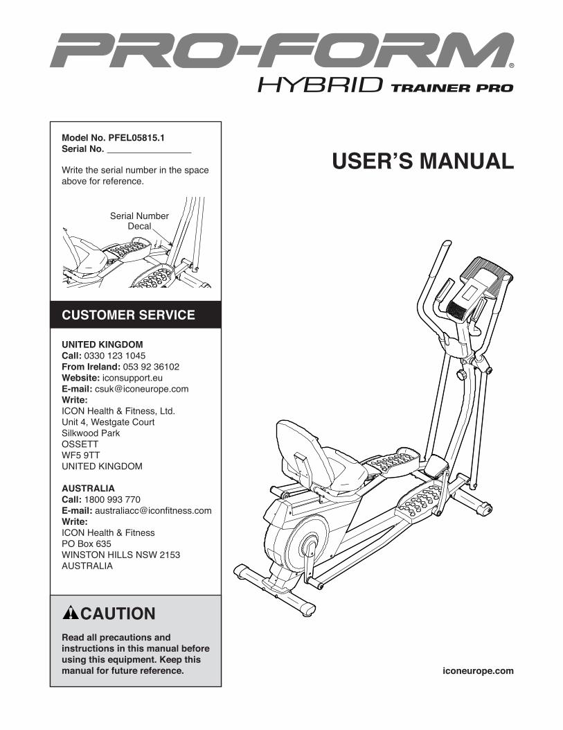
Model No. PFEL05815.1Serial No.
Write the serial number in the space above for reference.
USER’S MANUAL
Serial Number Decal
CUSTOMER SERVICE
UNITED KINGDOMCall: 0330 123 1045From Ireland: 053 92 36102Website: iconsupport.euE-mail: [email protected]: ICON Health & Fitness, Ltd.Unit 4, Westgate CourtSilkwood ParkOSSETTWF5 9TTUNITED KINGDOM
AUSTRALIACall: 1800 993 770E-mail: [email protected]:ICON Health & FitnessPO Box 635WINSTON HILLS NSW 2153AUSTRALIA
iconeurope.com
2
WARNING DECAL PLACEMENT
TABLE OF CONTENTSWARNING DECAL PLACEMENT . . . . . . . . . . . . . . . . . . . . . . . . . . . . . . . . . . . . . . . . . . . . . . . . . . . . . . . . . . . . . . .2IMPORTANT PRECAUTIONS . . . . . . . . . . . . . . . . . . . . . . . . . . . . . . . . . . . . . . . . . . . . . . . . . . . . . . . . . . . . . . . . . .3BEFORE YOU BEGIN. . . . . . . . . . . . . . . . . . . . . . . . . . . . . . . . . . . . . . . . . . . . . . . . . . . . . . . . . . . . . . . . . . . . . . . .4PART IDENTIFICATION CHART. . . . . . . . . . . . . . . . . . . . . . . . . . . . . . . . . . . . . . . . . . . . . . . . . . . . . . . . . . . . . . . .5ASSEMBLY . . . . . . . . . . . . . . . . . . . . . . . . . . . . . . . . . . . . . . . . . . . . . . . . . . . . . . . . . . . . . . . . . . . . . . . . . . . . . . . .6HOW TO USE THE HYBRID TRAINER . . . . . . . . . . . . . . . . . . . . . . . . . . . . . . . . . . . . . . . . . . . . . . . . . . . . . . . . .15MAINTENANCE AND TROUBLESHOOTING . . . . . . . . . . . . . . . . . . . . . . . . . . . . . . . . . . . . . . . . . . . . . . . . . . . .23EXERCISE GUIDELINES . . . . . . . . . . . . . . . . . . . . . . . . . . . . . . . . . . . . . . . . . . . . . . . . . . . . . . . . . . . . . . . . . . . .25PART LIST. . . . . . . . . . . . . . . . . . . . . . . . . . . . . . . . . . . . . . . . . . . . . . . . . . . . . . . . . . . . . . . . . . . . . . . . . . . . . . . .28EXPLODED DRAWING. . . . . . . . . . . . . . . . . . . . . . . . . . . . . . . . . . . . . . . . . . . . . . . . . . . . . . . . . . . . . . . . . . . . . .30ORDERING REPLACEMENT PARTS . . . . . . . . . . . . . . . . . . . . . . . . . . . . . . . . . . . . . . . . . . . . . . . . . . Back CoverRECYCLING INFORMATION . . . . . . . . . . . . . . . . . . . . . . . . . . . . . . . . . . . . . . . . . . . . . . . . . . . . . . . . . Back Cover
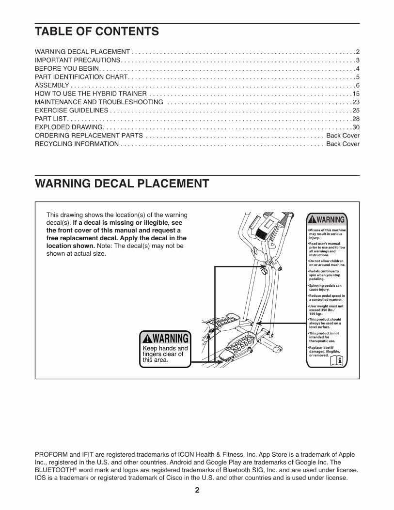
This drawing shows the location(s) of the warning decal(s). If a decal is missing or illegible, see the front cover of this manual and request a free replacement decal. Apply the decal in the location shown. Note: The decal(s) may not be shown at actual size.
PROFORM and IFIT are registered trademarks of ICON Health & Fitness, Inc. App Store is a trademark of Apple Inc., registered in the U.S. and other countries. Android and Google Play are trademarks of Google Inc. The BLUETOOTH® word mark and logos are registered trademarks of Bluetooth SIG, Inc. and are used under license. IOS is a trademark or registered trademark of Cisco in the U.S. and other countries and is used under license.

3
WARNING: To reduce the risk of serious injury, read all important precautions and instructions in this manual and all warnings on the hybrid trainer before using the hybrid trainer. ICON assumes no responsibility for personal injury or property damage sustained by or through the use of this product.
1. It is the responsibility of the owner to ensure that all users of the hybrid trainer are adequately informed of all precautions.
2. Before beginning any exercise program, consult your physician. This is especially important for persons over age 35 or per-sons with pre-existing health problems.
3. The hybrid trainer is not intended for use by persons with reduced physical, sensory, or mental capabilities or lack of experience and knowledge, unless they are given supervi-sion or instruction about use of the hybrid trainer by someone responsible for their safety.
4. Use the hybrid trainer only as described in this manual.
5. The hybrid trainer is intended for home use only. Do not use the hybrid trainer in a com-mercial, rental, or institutional setting.
6. Keep the hybrid trainer indoors, away from moisture and dust. Do not put the hybrid trainer in a garage or covered patio or near water.
7. Place the hybrid trainer on a level surface, with at least 3 ft. (0.9 m) of clearance in the front and rear of the hybrid trainer and 2 ft. (0.6 m) on each side. To protect the floor or carpet from damage, place a mat under the hybrid trainer.
8. Inspect and properly tighten all parts each time the hybrid trainer is used. Replace any worn parts immediately.
9. Keep children under age 13 and pets away from the hybrid trainer at all times.
10. The hybrid trainer should not be used by persons weighing more than 350 lbs. (159 kg).
11. Wear appropriate clothes while exercis-ing; do not wear loose clothes that could become caught on the hybrid trainer. Always wear athletic shoes for foot protection while exercising.
12. Hold the handlebars or the upper body arms when mounting, dismounting, or using the hybrid trainer.
13. Make sure that the pedal knobs are fully tightened each time you use the hybrid trainer.
14. The heart rate monitor is not a medical device. Various factors may affect the accu-racy of heart rate readings. The heart rate monitor is intended only as an exercise aid in determining heart rate trends in general.
15. The hybrid trainer does not have a freewheel; the pedals will continue to move until the flywheel stops. Reduce your pedaling speed in a controlled way.
16. Keep your back straight while using the hybrid trainer; do not arch your back.
17. Over exercising may result in serious injury or death. If you feel faint, if you become short of breath, or if you experience pain while exercising, stop immediately and cool down.
IMPORTANT PRECAUTIONS
4
BEFORE YOU BEGINThank you for selecting the revolutionary PROFORM® HYBRID TRAINER PRO. The HYBRID TRAINER PRO provides an impressive selection of features designed to make your workouts at home more effective and enjoyable.
For your benefit, read this manual carefully before you use the hybrid trainer. If you have questions after
reading this manual, please see the front cover of this manual. To help us assist you, note the product model number and serial number before contacting us. The model number and the location of the serial number decal are shown on the front cover of this manual.
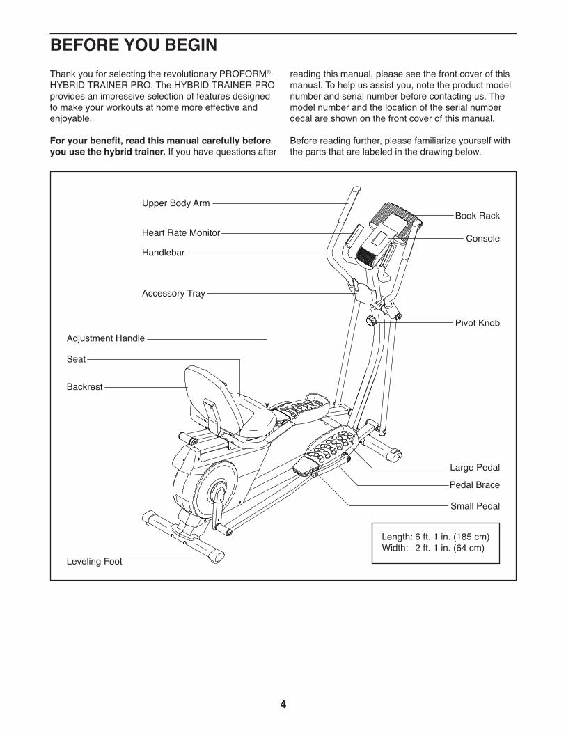
Before reading further, please familiarize yourself with the parts that are labeled in the drawing below.
Length: 6 ft. 1 in. (185 cm)Width: 2 ft. 1 in. (64 cm)
Handlebar
Seat
Pivot Knob
Console
Book Rack
Large Pedal
Small Pedal
Pedal Brace
Heart Rate Monitor
Backrest
Accessory Tray
Leveling Foot
Adjustment Handle
Upper Body Arm

5
M10 x 80mm Screw (19)–4M10 x 20mm Screw (76)–6
M8 Locknut (68)–10
M8 Washer (87)–6
M8 x 38mm Bolt (95)–4
M8 x 12mm Screw (106)–6
M8 x 14mmShoulder
Screw (86)–6
M8 x 38mm Hex Bolt (102)–6
M4 x 16mm Screw (115)–6
M6 x 35mm Screw (98)–4
M6 x 20mm Screw (97)–4
PART IDENTIFICATION CHARTUse the drawings below to identify the small parts needed for assembly. The number in parentheses below each drawing is the key number of the part, from the PART LIST near the end of this manual. The number following the key number is the quantity needed for assembly. Note: If a part is not in the hardware kit, check to see if it has been preassembled. Extra parts may be included.
6
• Assembly requires two persons.
• Place all parts in a cleared area and remove the packing materials. Do not dispose of the packing materials until you finish assembly.
• Left parts are marked “L” or “Left” and right parts are marked “R” or “Right.”
• To identify small parts, see page 5.
• In addition to the included tool(s), assembly requires the following tools:
one Phillips screwdriver
one adjustable wrench
one rubber mallet
Assembly may be easier if you have a set of wrenches. To avoid damaging parts, do not use power tools.
ASSEMBLY
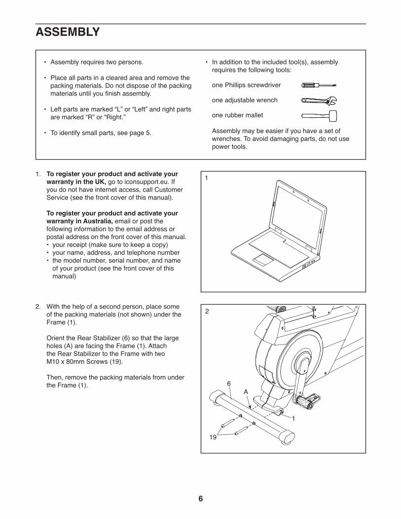
2. With the help of a second person, place some of the packing materials (not shown) under the Frame (1).
Orient the Rear Stabilizer (6) so that the large holes (A) are facing the Frame (1). Attach the Rear Stabilizer to the Frame with two M10 x 80mm Screws (19).
Then, remove the packing materials from under the Frame (1).
2
19
1
6A
11. To register your product and activate your warranty in the UK, go to iconsupport.eu. If you do not have internet access, call Customer Service (see the front cover of this manual).
To register your product and activate your warranty in Australia, email or post the following information to the email address or postal address on the front cover of this manual.
• your receipt (make sure to keep a copy) • your name, address, and telephone number • the model number, serial number, and name
of your product (see the front cover of this manual)
7
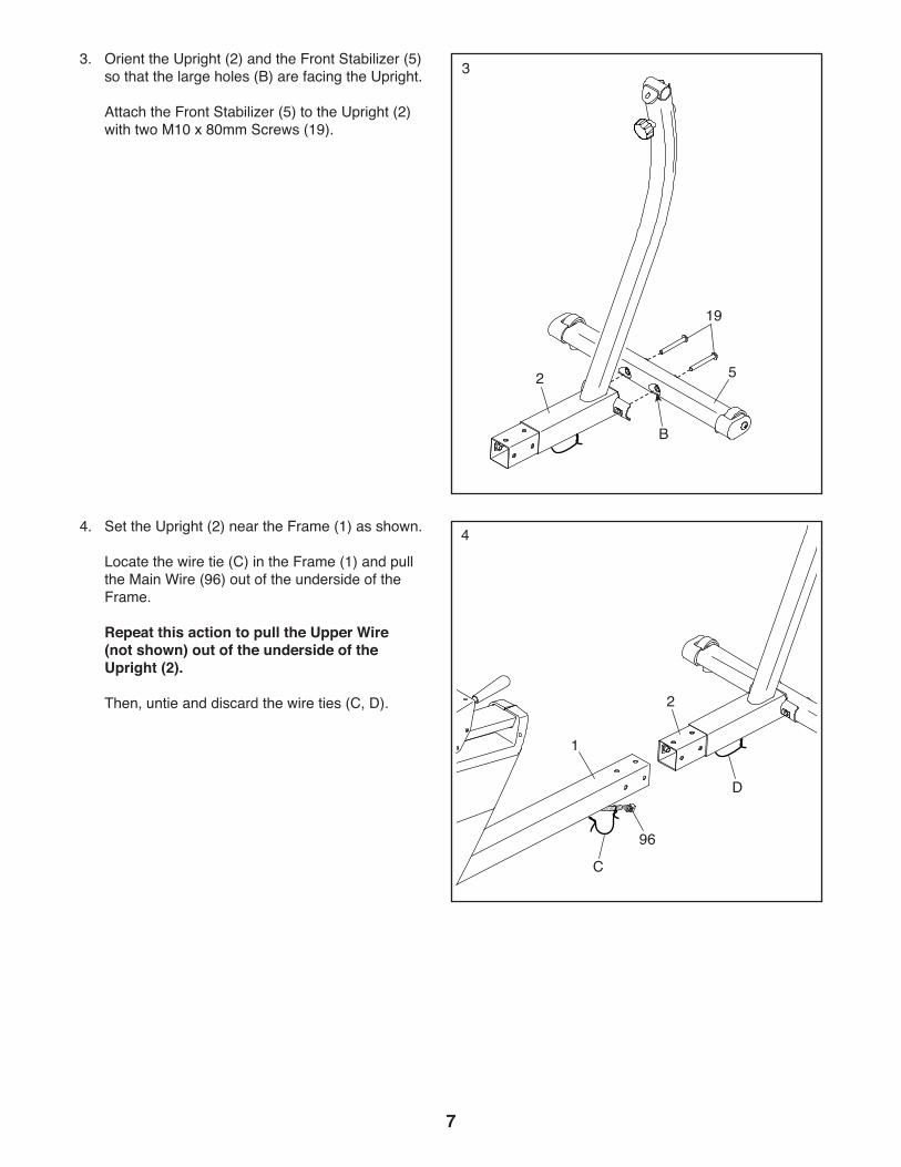
44. Set the Upright (2) near the Frame (1) as shown.
Locate the wire tie (C) in the Frame (1) and pull the Main Wire (96) out of the underside of the Frame.
Repeat this action to pull the Upper Wire (not shown) out of the underside of the Upright (2).
Then, untie and discard the wire ties (C, D).
96
33. Orient the Upright (2) and the Front Stabilizer (5) so that the large holes (B) are facing the Upright.
Attach the Front Stabilizer (5) to the Upright (2) with two M10 x 80mm Screws (19).
19
52
2
1
B
C
D

8
5
76
7696
94
76
5. Tip: Avoid pinching the wires. Insert the Upright (2) into the Frame (1).
Attach the Upright (2) with six M10 x 20mm Screws (76); start all the Screws, and then tighten them.
Then, connect the Upper Wire (94) to the Main Wire (96).
Avoid pinching the wires
Avoid pinching the wires
66. Locate the wire tie (D) in the top of the Upright (2) and pull the Upper Wire (94) out of the Upright. Then, untie and discard the wire tie.
Tip: Avoid pinching the wires. Attach the Wire Cover (20) to the Frame (1) and the Upright (2) with two M4 x 16mm Screws (115). Make sure that the tab (E) on the Wire Cover is in the location shown.
115
E
20
94
2
2
1
1
D
9
94
3
2
2
3
Grease
Avoid pinching the Upper Wire (94)
8
13
94 80
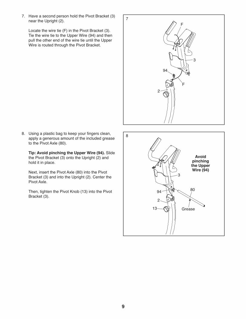
8. Using a plastic bag to keep your fingers clean, apply a generous amount of the included grease to the Pivot Axle (80).
Tip: Avoid pinching the Upper Wire (94). Slide the Pivot Bracket (3) onto the Upright (2) and hold it in place.
Next, insert the Pivot Axle (80) into the Pivot Bracket (3) and into the Upright (2). Center the Pivot Axle.
Then, tighten the Pivot Knob (13) into the Pivot Bracket (3).
77. Have a second person hold the Pivot Bracket (3) near the Upright (2).
Locate the wire tie (F) in the Pivot Bracket (3). Tie the wire tie to the Upper Wire (94) and then pull the other end of the wire tie until the Upper Wire is routed through the Pivot Bracket.
F
F
10
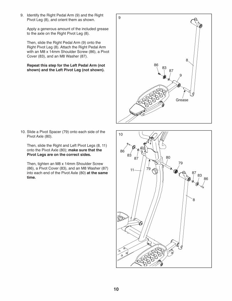
99. Identify the Right Pedal Arm (9) and the Right Pivot Leg (8), and orient them as shown.
Apply a generous amount of the included grease to the axle on the Right Pivot Leg (8).
Then, slide the Right Pedal Arm (9) onto the Right Pivot Leg (8). Attach the Right Pedal Arm with an M8 x 14mm Shoulder Screw (86), a Pivot Cover (83), and an M8 Washer (87).
Repeat this step for the Left Pedal Arm (not shown) and the Left Pivot Leg (not shown).
8683
87
8
11
8
9
10
7979
80
87
87
86
86
83
83
10. Slide a Pivot Spacer (79) onto each side of the Pivot Axle (80).
Then, slide the Right and Left Pivot Legs (8, 11) onto the Pivot Axle (80); make sure that the Pivot Legs are on the correct sides.
Then, tighten an M8 x 14mm Shoulder Screw (86), a Pivot Cover (83), and an M8 Washer (87) into each end of the Pivot Axle (80) at the same time.
Grease
11
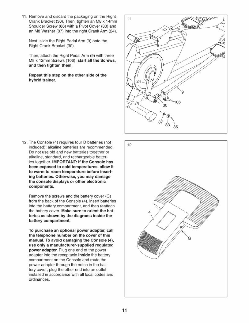
1111. Remove and discard the packaging on the Right Crank Bracket (30). Then, tighten an M8 x 14mm Shoulder Screw (86) with a Pivot Cover (83) and an M8 Washer (87) into the right Crank Arm (24).
Next, slide the Right Pedal Arm (9) onto the Right Crank Bracket (30).
Then, attach the Right Pedal Arm (9) with three M8 x 12mm Screws (106); start all the Screws, and then tighten them.
Repeat this step on the other side of the hybrid trainer.
10630
868387
9
1212. The Console (4) requires four D batteries (not included); alkaline batteries are recommended. Do not use old and new batteries together or alkaline, standard, and rechargeable batter-ies together. IMPORTANT: If the Console has been exposed to cold temperatures, allow it to warm to room temperature before insert-ing batteries. Otherwise, you may damage the console displays or other electronic components.
Remove the screws and the battery cover (G) from the back of the Console (4), insert batteries into the battery compartment, and then reattach the battery cover. Make sure to orient the bat-teries as shown by the diagrams inside the battery compartment.
To purchase an optional power adapter, call the telephone number on the cover of this manual. To avoid damaging the Console (4), use only a manufacturer-supplied regulated power adapter. Plug one end of the power adapter into the receptacle inside the battery compartment on the Console and route the power adapter through the notch in the bat-tery cover; plug the other end into an outlet installed in accordance with all local codes and ordinances.
G
4
24
12
13
115
94103, 104
3
4
Avoid pinching the wires
14
102
7
8
78
68
68
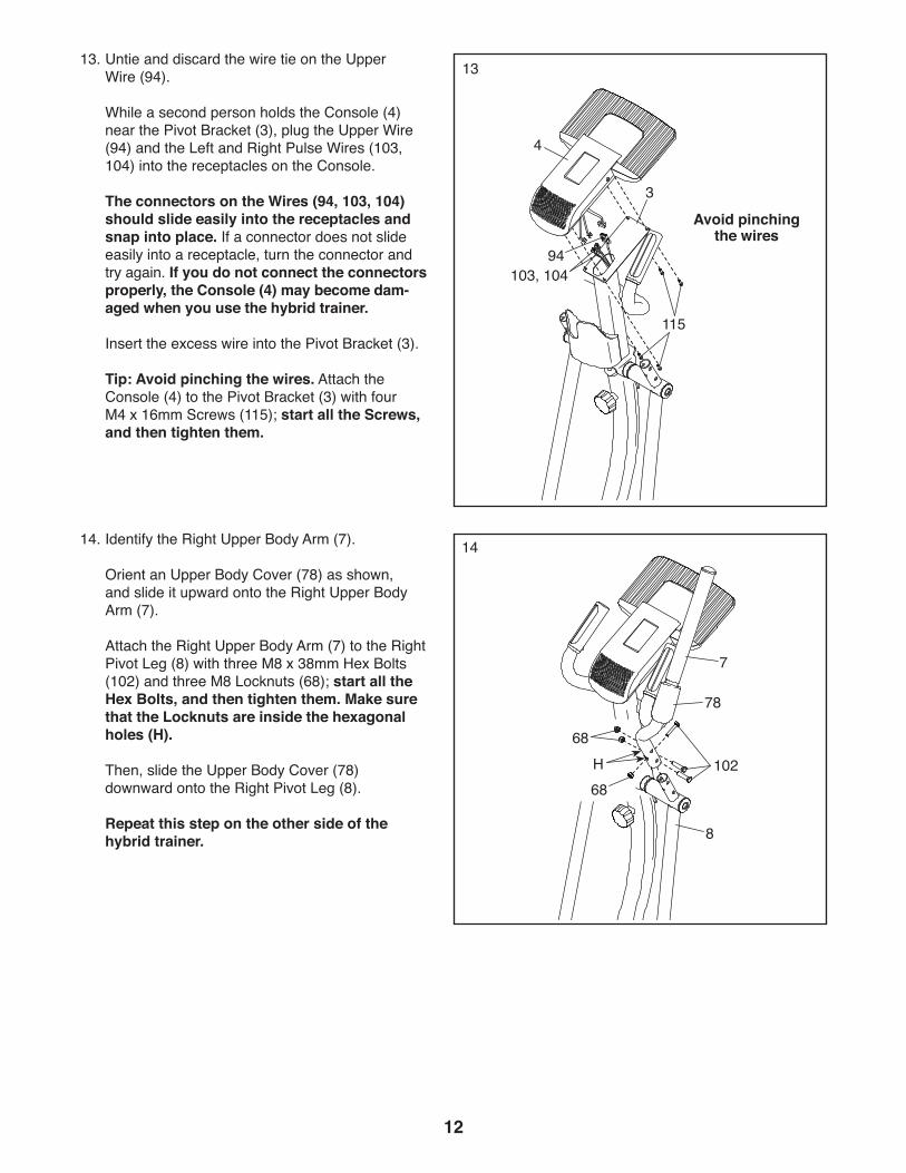
14. Identify the Right Upper Body Arm (7).
Orient an Upper Body Cover (78) as shown, and slide it upward onto the Right Upper Body Arm (7).
Attach the Right Upper Body Arm (7) to the Right Pivot Leg (8) with three M8 x 38mm Hex Bolts (102) and three M8 Locknuts (68); start all the Hex Bolts, and then tighten them. Make sure that the Locknuts are inside the hexagonal holes (H).
Then, slide the Upper Body Cover (78) downward onto the Right Pivot Leg (8).
Repeat this step on the other side of the hybrid trainer.
H
13. Untie and discard the wire tie on the Upper Wire (94).
While a second person holds the Console (4) near the Pivot Bracket (3), plug the Upper Wire (94) and the Left and Right Pulse Wires (103, 104) into the receptacles on the Console.
The connectors on the Wires (94, 103, 104) should slide easily into the receptacles and snap into place. If a connector does not slide easily into a receptacle, turn the connector and try again. If you do not connect the connectors properly, the Console (4) may become dam-aged when you use the hybrid trainer.
Insert the excess wire into the Pivot Bracket (3).
Tip: Avoid pinching the wires. Attach the Console (4) to the Pivot Bracket (3) with four M4 x 16mm Screws (115); start all the Screws, and then tighten them.
13
15
6168
29
93
95
I
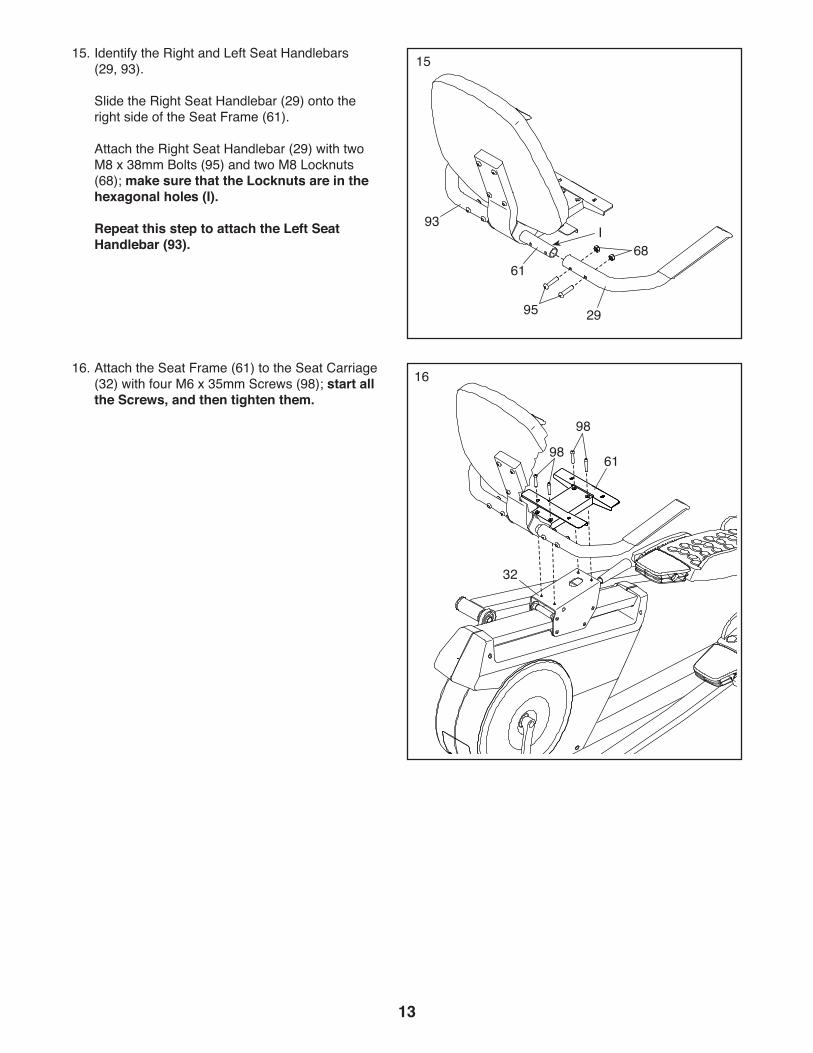
15. Identify the Right and Left Seat Handlebars (29, 93).
Slide the Right Seat Handlebar (29) onto the right side of the Seat Frame (61).
Attach the Right Seat Handlebar (29) with two M8 x 38mm Bolts (95) and two M8 Locknuts (68); make sure that the Locknuts are in the hexagonal holes (I).
Repeat this step to attach the Left Seat Handlebar (93).
1616. Attach the Seat Frame (61) to the Seat Carriage (32) with four M6 x 35mm Screws (98); start all the Screws, and then tighten them.
61
98
98
32
14
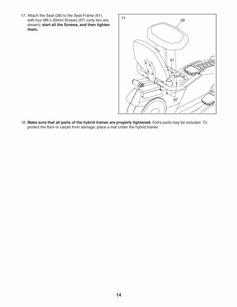
1717. Attach the Seat (28) to the Seat Frame (61) with four M6 x 20mm Screws (97) (only two are shown); start all the Screws, and then tighten them.
18. Make sure that all parts of the hybrid trainer are properly tightened. Extra parts may be included. To protect the floor or carpet from damage, place a mat under the hybrid trainer.
28
61
97
15
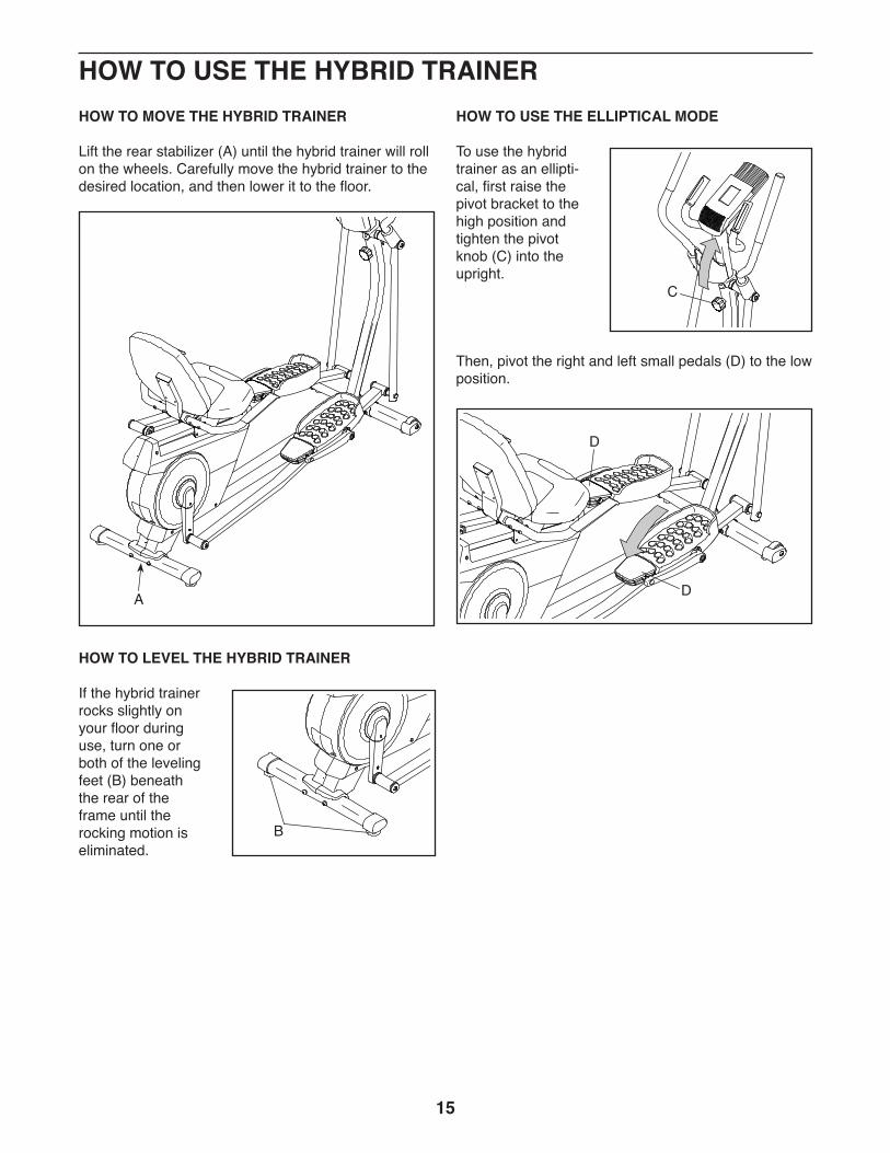
HOW TO MOVE THE HYBRID TRAINER
Lift the rear stabilizer (A) until the hybrid trainer will roll on the wheels. Carefully move the hybrid trainer to the desired location, and then lower it to the floor.
HOW TO LEVEL THE HYBRID TRAINER
If the hybrid trainer rocks slightly on your floor during use, turn one or both of the leveling feet (B) beneath the rear of the frame until the rocking motion is eliminated.
HOW TO USE THE ELLIPTICAL MODE
To use the hybrid trainer as an ellipti-cal, first raise the pivot bracket to the high position and tighten the pivot knob (C) into the upright.
Then, pivot the right and left small pedals (D) to the low position.
A
B
C
D
D
HOW TO USE THE HYBRID TRAINER
16
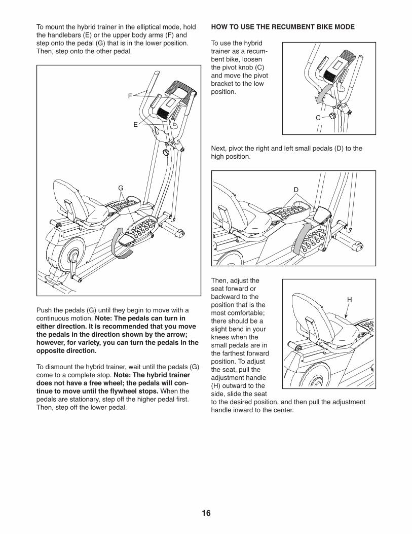
To mount the hybrid trainer in the elliptical mode, hold the handlebars (E) or the upper body arms (F) and step onto the pedal (G) that is in the lower position. Then, step onto the other pedal.
Push the pedals (G) until they begin to move with a continuous motion. Note: The pedals can turn in either direction. It is recommended that you move the pedals in the direction shown by the arrow; however, for variety, you can turn the pedals in the opposite direction.
To dismount the hybrid trainer, wait until the pedals (G) come to a complete stop. Note: The hybrid trainer does not have a free wheel; the pedals will con-tinue to move until the flywheel stops. When the pedals are stationary, step off the higher pedal first. Then, step off the lower pedal.
HOW TO USE THE RECUMBENT BIKE MODE
To use the hybrid trainer as a recum-bent bike, loosen the pivot knob (C) and move the pivot bracket to the low position.
Next, pivot the right and left small pedals (D) to the high position.
Then, adjust the seat forward or backward to the position that is the most comfortable; there should be a slight bend in your knees when the small pedals are in the farthest forward position. To adjust the seat, pull the adjustment handle (H) outward to the side, slide the seat to the desired position, and then pull the adjustment handle inward to the center.
G
F
E
D
H
C
17
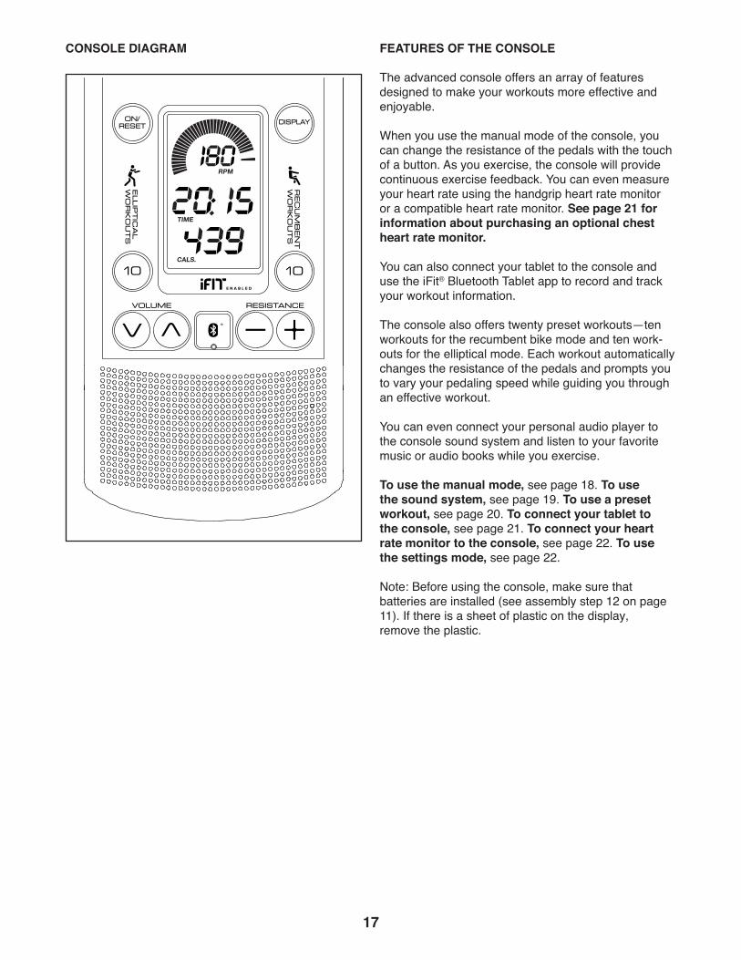
CONSOLE DIAGRAM FEATURES OF THE CONSOLE
The advanced console offers an array of features designed to make your workouts more effective and enjoyable.
When you use the manual mode of the console, you can change the resistance of the pedals with the touch of a button. As you exercise, the console will provide continuous exercise feedback. You can even measure your heart rate using the handgrip heart rate monitor or a compatible heart rate monitor. See page 21 for information about purchasing an optional chest heart rate monitor.
You can also connect your tablet to the console and use the iFit® Bluetooth Tablet app to record and track your workout information.
The console also offers twenty preset workouts—ten workouts for the recumbent bike mode and ten work-outs for the elliptical mode. Each workout automatically changes the resistance of the pedals and prompts you to vary your pedaling speed while guiding you through an effective workout.
You can even connect your personal audio player to the console sound system and listen to your favorite music or audio books while you exercise.
To use the manual mode, see page 18. To use the sound system, see page 19. To use a preset workout, see page 20. To connect your tablet to the console, see page 21. To connect your heart rate monitor to the console, see page 22. To use the settings mode, see page 22.
Note: Before using the console, make sure that batteries are installed (see assembly step 12 on page 11). If there is a sheet of plastic on the display, remove the plastic.
AudiELPF05815
PFEL05815
18
HOW TO USE THE MANUAL MODE
1. Turn on the console.
Press any button or begin pedaling to turn on the console.
When you turn on the console, the displays will turn on, a tone will sound, and the console will be ready for use.
2. Select the manual mode.
When you turn on the con-sole, the manual mode will be selected automatically.
If you have selected a workout, reselect the manual mode by pressing the On/Reset button.
3. Begin pedaling and change the resistance of the pedals as desired.
As you pedal, change the resistance of the pedals by pressing the Resistance increase and decrease buttons.
Note: After you press the buttons, it will take a moment for the pedals to reach the selected resistance level.
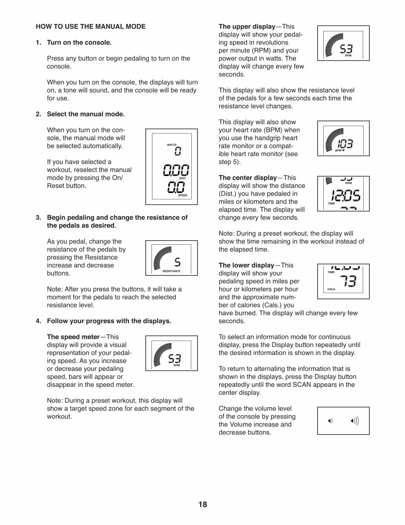
4. Follow your progress with the displays.
The speed meter—This display will provide a visual representation of your pedal-ing speed. As you increase or decrease your pedaling speed, bars will appear or disappear in the speed meter.
Note: During a preset workout, this display will show a target speed zone for each segment of the workout.
The upper display—This display will show your pedal-ing speed in revolutions per minute (RPM) and your power output in watts. The display will change every few seconds.
This display will also show the resistance level of the pedals for a few seconds each time the resistance level changes.
This display will also show your heart rate (BPM) when you use the handgrip heart rate monitor or a compat-ible heart rate monitor (see step 5).
The center display—This display will show the distance (Dist.) you have pedaled in miles or kilometers and the elapsed time. The display will change every few seconds.
Note: During a preset workout, the display will show the time remaining in the workout instead of the elapsed time.
The lower display—This display will show your pedaling speed in miles per hour or kilometers per hour and the approximate num-ber of calories (Cals.) you have burned. The display will change every few seconds.
To select an information mode for continuous display, press the Display button repeatedly until the desired information is shown in the display.
To return to alternating the information that is shown in the displays, press the Display button repeatedly until the word SCAN appears in the center display.
Change the volume level of the console by pressing the Volume increase and decrease buttons.
19
To pause the console, stop pedaling. When the console is paused, the displays will pause. To continue your workout, simply resume pedaling.
To reset the displays to zero, press the On/Reset button.
Note: The console can show pedaling speed and distance in either miles or kilometers. To change the unit of measurement, see THE SETTINGS MODE on page 22.
5. Measure your heart rate if desired.
You can measure your heart rate using either the handgrip heart rate monitor or a compatible heart rate monitor. For information about pur-chasing an optional chest heart rate monitor, see page 21.
The console is compatible with all BLUETOOTH® Smart heart rate monitors. To connect your heart rate monitor to the console, see page 22.
Note: If you use both heart rate monitors at the same time, the BLUETOOTH Smart heart rate monitor will have priority.
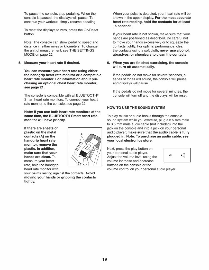
If there are sheets of plastic on the metal contacts (A) on the handgrip heart rate monitor, remove the plastic. In addition, make sure that your hands are clean. To measure your heart rate, hold the handgrip heart rate monitor with your palms resting against the contacts. Avoid moving your hands or gripping the contacts tightly.
When your pulse is detected, your heart rate will be shown in the upper display. For the most accurate heart rate reading, hold the contacts for at least 15 seconds.
If your heart rate is not shown, make sure that your hands are positioned as described. Be careful not to move your hands excessively or to squeeze the contacts tightly. For optimal performance, clean the contacts using a soft cloth; never use alcohol, abrasives, or chemicals to clean the contacts.
6. When you are finished exercising, the console will turn off automatically.
If the pedals do not move for several seconds, a series of tones will sound, the console will pause, and displays will pause.
If the pedals do not move for several minutes, the console will turn off and the displays will be reset.
HOW TO USE THE SOUND SYSTEM
To play music or audio books through the console sound system while you exercise, plug a 3.5 mm male to 3.5 mm male audio cable (not included) into the jack on the console and into a jack on your personal audio player; make sure that the audio cable is fully plugged in. Note: To purchase an audio cable, see your local electronics store.
Next, press the play button on your personal audio player. Adjust the volume level using the volume increase and decrease buttons on the console or the volume control on your personal audio player.
A
20
HOW TO USE A PRESET WORKOUT
1. Turn on the console.
Press any button or begin pedaling to turn on the console.
When you turn on the console, the displays will turn on, a tone will sound, and the console will be ready for use.
2. Select a preset workout.
When you select a Recumbent preset workout, you must adjust the hybrid trainer to the recumbent bike mode for the console to provide accurate feed-back (see HOW TO USE THE RECUMBENT BIKE MODE on page 16).
When you select an Elliptical preset workout, you must adjust the hybrid trainer to the elliptical mode for the console to provide accurate feedback (see HOW TO USE THE ELLIPTICAL MODE on page 15).
To select a preset workout, press the Elliptical Workouts or Recumbent Workouts button repeatedly until the number of the desired workout appears in the lower display. The duration of the workout will appear in the center display.
3. Start the workout.
Begin pedaling to start the workout.
Each workout is divided into one-minute segments. One resistance level and one target speed are programmed for each segment. Note: The same resistance level and/or target speed may be pro-grammed for consecutive segments.
At the end of each segment of the workout, a series of tones will sound. The resistance level for the next segment will appear in the upper display for a few seconds to alert you. The resistance of the pedals will then change.
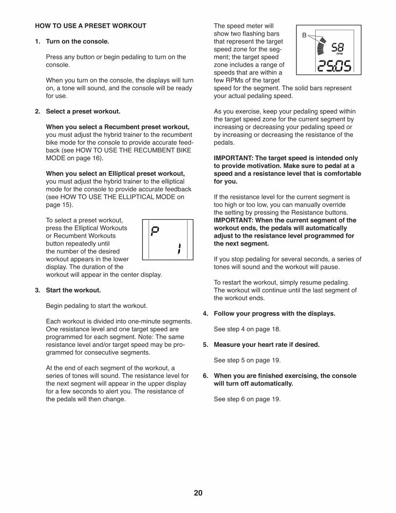
The speed meter will show two flashing bars that represent the target speed zone for the seg-ment; the target speed zone includes a range of speeds that are within a few RPMs of the target speed for the segment. The solid bars represent your actual pedaling speed.
As you exercise, keep your pedaling speed within the target speed zone for the current segment by increasing or decreasing your pedaling speed or by increasing or decreasing the resistance of the pedals.
IMPORTANT: The target speed is intended only to provide motivation. Make sure to pedal at a speed and a resistance level that is comfortable for you.
If the resistance level for the current segment is too high or too low, you can manually override the setting by pressing the Resistance buttons. IMPORTANT: When the current segment of the workout ends, the pedals will automatically adjust to the resistance level programmed for the next segment.
If you stop pedaling for several seconds, a series of tones will sound and the workout will pause.
To restart the workout, simply resume pedaling. The workout will continue until the last segment of the workout ends.
4. Follow your progress with the displays.
See step 4 on page 18.
5. Measure your heart rate if desired.
See step 5 on page 19.
6. When you are finished exercising, the console will turn off automatically.
See step 6 on page 19.
B
21
THE OPTIONAL CHEST HEART RATE MONITOR
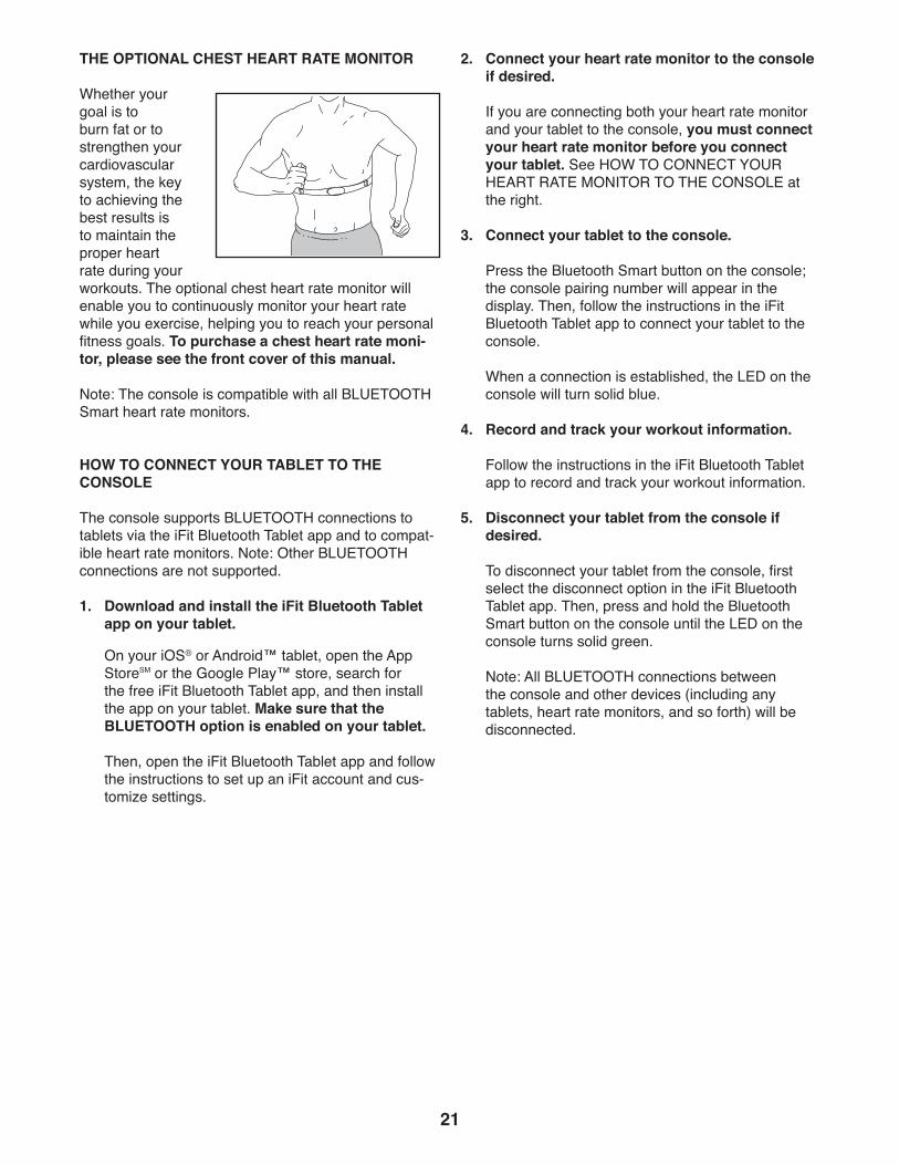
Whether your goal is to burn fat or to strengthen your cardiovascular system, the key to achieving the best results is to maintain the proper heart rate during your workouts. The optional chest heart rate monitor will enable you to continuously monitor your heart rate while you exercise, helping you to reach your personal fitness goals. To purchase a chest heart rate moni-tor, please see the front cover of this manual.
Note: The console is compatible with all BLUETOOTH Smart heart rate monitors.
HOW TO CONNECT YOUR TABLET TO THE CONSOLE
The console supports BLUETOOTH connections to tablets via the iFit Bluetooth Tablet app and to compat-ible heart rate monitors. Note: Other BLUETOOTH connections are not supported.
1. Download and install the iFit Bluetooth Tablet app on your tablet.
On your iOS® or Android™ tablet, open the App Store℠ or the Google Play™ store, search for the free iFit Bluetooth Tablet app, and then install the app on your tablet. Make sure that the BLUETOOTH option is enabled on your tablet.
Then, open the iFit Bluetooth Tablet app and follow the instructions to set up an iFit account and cus-tomize settings.
2. Connect your heart rate monitor to the console if desired.
If you are connecting both your heart rate monitor and your tablet to the console, you must connect your heart rate monitor before you connect your tablet. See HOW TO CONNECT YOUR HEART RATE MONITOR TO THE CONSOLE at the right.
3. Connect your tablet to the console.
Press the Bluetooth Smart button on the console; the console pairing number will appear in the display. Then, follow the instructions in the iFit Bluetooth Tablet app to connect your tablet to the console.
When a connection is established, the LED on the console will turn solid blue.
4. Record and track your workout information.
Follow the instructions in the iFit Bluetooth Tablet app to record and track your workout information.
5. Disconnect your tablet from the console if desired.
To disconnect your tablet from the console, first select the disconnect option in the iFit Bluetooth Tablet app. Then, press and hold the Bluetooth Smart button on the console until the LED on the console turns solid green.
Note: All BLUETOOTH connections between the console and other devices (including any tablets, heart rate monitors, and so forth) will be disconnected.
22
HOW TO CONNECT YOUR HEART RATE MONITOR TO THE CONSOLE
The console is compatible with all BLUETOOTH Smart heart rate monitors.
To connect your BLUETOOTH Smart heart rate moni-tor to the console, press the Bluetooth Smart button on the console. When a connection is established, the LED on the console will flash red twice.
Note: If there is more than one compatible heart rate monitor near the console, the console will connect to the heart rate monitor with the strongest signal.
To disconnect your heart rate monitor from the console, press and hold the Bluetooth Smart button on the con-sole for 5 seconds.
Note: All BLUETOOTH connections between the con-sole and other devices (including any smart devices, heart rate monitors, and so forth) will be disconnected.
THE SETTINGS MODE
The console features a settings mode that allows you to select a unit of measurement for the console and to view console usage information.
To select the settings mode, press and hold down the On/Reset button until the settings mode information appears in the display.
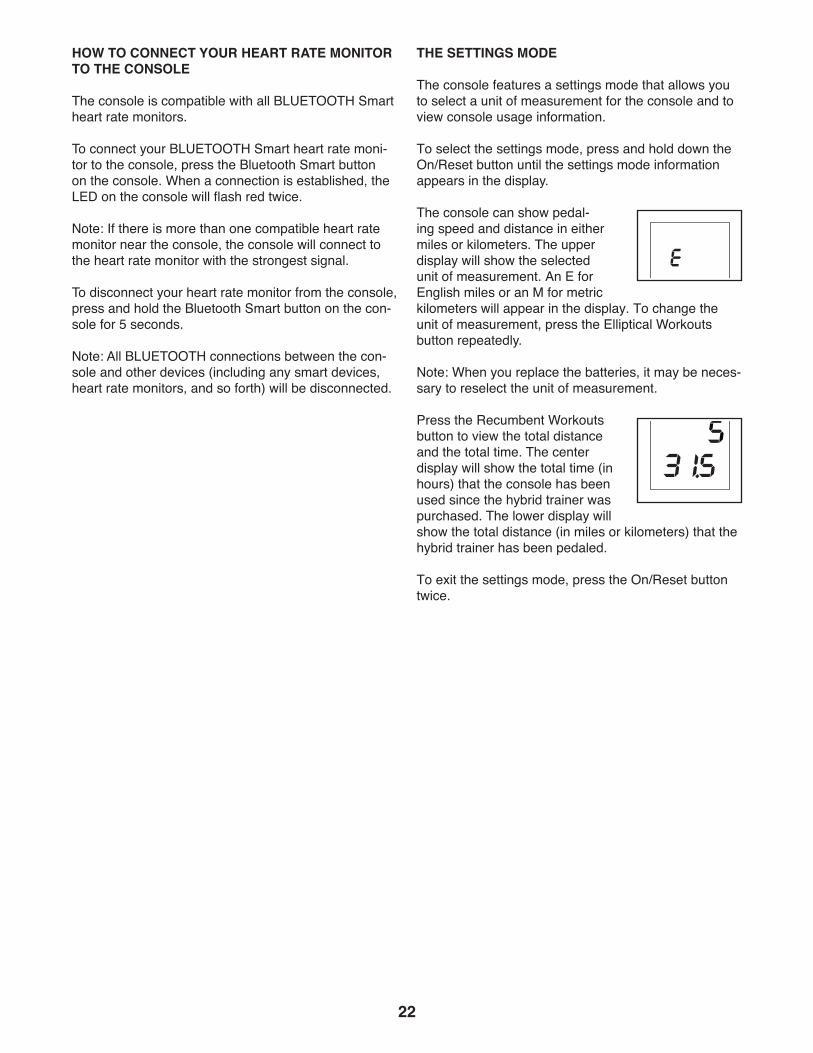
The console can show pedal-ing speed and distance in either miles or kilometers. The upper display will show the selected unit of measurement. An E for English miles or an M for metric kilometers will appear in the display. To change the unit of measurement, press the Elliptical Workouts button repeatedly.
Note: When you replace the batteries, it may be neces-sary to reselect the unit of measurement.
Press the Recumbent Workouts button to view the total distance and the total time. The center display will show the total time (in hours) that the console has been used since the hybrid trainer was purchased. The lower display will show the total distance (in miles or kilometers) that the hybrid trainer has been pedaled.
To exit the settings mode, press the On/Reset button twice.
23
MAINTENANCE
Regular maintenance is important for optimal performance and to reduce wear. Inspect and properly tighten all parts each time the hybrid trainer is used. Replace any worn parts immediately.
To clean the hybrid trainer, use a damp cloth and a small amount of mild soap. IMPORTANT: To avoid damage to the console, keep liquids away from the console and keep the console out of direct sunlight.
CONSOLE TROUBLESHOOTING
Most console problems are the result of low batter-ies. To replace the batteries, see assembly step 12 on page 11.
If the console does not display your heart rate when you use the handgrip heart rate monitor, see step 5 on page 19.
HOW TO ADJUST THE REED SWITCH
If the console does not display correct feedback, the reed switch should be adjusted.
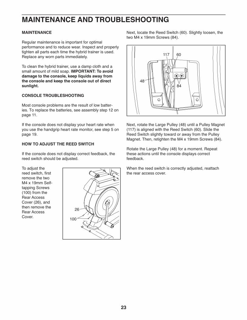
To adjust the reed switch, first remove the two M4 x 19mm Self-tapping Screws (100) from the Rear Access Cover (26), and then remove the Rear Access Cover.
Next, locate the Reed Switch (60). Slightly loosen, the two M4 x 19mm Screws (84).
Next, rotate the Large Pulley (48) until a Pulley Magnet (117) is aligned with the Reed Switch (60). Slide the Reed Switch slightly toward or away from the Pulley Magnet. Then, retighten the M4 x 19mm Screws (84).
Rotate the Large Pulley (48) for a moment. Repeat these actions until the console displays correct feedback.
When the reed switch is correctly adjusted, reattach the rear access cover.
100
26
MAINTENANCE AND TROUBLESHOOTING
60
84
117
48
24
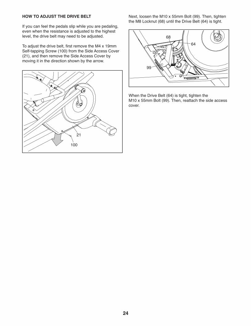
HOW TO ADJUST THE DRIVE BELT
If you can feel the pedals slip while you are pedaling, even when the resistance is adjusted to the highest level, the drive belt may need to be adjusted.
To adjust the drive belt, first remove the M4 x 19mm Self-tapping Screw (100) from the Side Access Cover (21), and then remove the Side Access Cover by moving it in the direction shown by the arrow.
Next, loosen the M10 x 55mm Bolt (99). Then, tighten the M8 Locknut (68) until the Drive Belt (64) is tight.
When the Drive Belt (64) is tight, tighten the M10 x 55mm Bolt (99). Then, reattach the side access cover.
100
21
6864
99

25
EXERCISE GUIDELINES
These guidelines will help you to plan your exercise program. For detailed exercise information, obtain a reputable book or consult your physician. Remember, proper nutrition and adequate rest are essential for successful results.
EXERCISE INTENSITY
Whether your goal is to burn fat or to strengthen your cardiovascular system, exercising at the proper inten-sity is the key to achieving results. You can use your heart rate as a guide to find the proper intensity level. The chart below shows recommended heart rates for fat burning and aerobic exercise.
To find the proper intensity level, find your age at the bottom of the chart (ages are rounded off to the near-est ten years). The three numbers listed above your age define your “training zone.” The lowest number is the heart rate for fat burning, the middle number is the heart rate for maximum fat burning, and the highest number is the heart rate for aerobic exercise.
Burning Fat—To burn fat effectively, you must exer-cise at a low intensity level for a sustained period of time. During the first few minutes of exercise, your body uses carbohydrate calories for energy. Only after the first few minutes of exercise does your body begin to use stored fat calories for energy. If your goal is to burn fat, adjust the intensity of your exercise until your heart rate is near the lowest number in your training zone. For maximum fat burning, exercise with your heart rate near the middle number in your training zone.
Aerobic Exercise—If your goal is to strengthen your cardiovascular system, you must perform aerobic exercise, which is activity that requires large amounts of oxygen for prolonged periods of time. For aerobic exercise, adjust the intensity of your exercise until your heart rate is near the highest number in your training zone.
WORKOUT GUIDELINES
Warming Up—Start with 5 to 10 minutes of stretch-ing and light exercise. A warm-up increases your body temperature, heart rate, and circulation in preparation for exercise.
Training Zone Exercise—Exercise for 20 to 30 min-utes with your heart rate in your training zone. (During the first few weeks of your exercise program, do not keep your heart rate in your training zone for longer than 20 minutes.) Breathe regularly and deeply as you exercise ; never hold your breath.
Cooling Down—Finish with 5 to 10 minutes of stretch-ing. Stretching increases the flexibility of your muscles and helps to prevent post-exercise problems.
EXERCISE FREQUENCY
To maintain or improve your condition, complete three workouts each week, with at least one day of rest between workouts. After a few months of regular exer-cise, you may complete up to five workouts each week, if desired. Remember, the key to success is to make exercise a regular and enjoyable part of your everyday life.
WARNING: Before beginning this or any exercise program, consult your physi-cian. This is especially important for persons over age 35 or persons with pre-existing health problems.
The heart rate monitor is not a medical device. Various factors may affect the accuracy of heart rate readings. The heart rate monitor is intended only as an exercise aid in determin-ing heart rate trends in general.
26
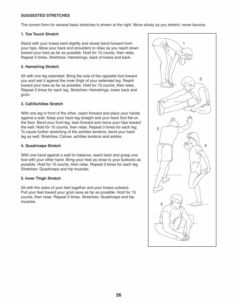
SUGGESTED STRETCHES
The correct form for several basic stretches is shown at the right. Move slowly as you stretch; never bounce.
1. Toe Touch Stretch
Stand with your knees bent slightly and slowly bend forward from your hips. Allow your back and shoulders to relax as you reach down toward your toes as far as possible. Hold for 15 counts, then relax. Repeat 3 times. Stretches: Hamstrings, back of knees and back.
2. Hamstring Stretch
Sit with one leg extended. Bring the sole of the opposite foot toward you and rest it against the inner thigh of your extended leg. Reach toward your toes as far as possible. Hold for 15 counts, then relax. Repeat 3 times for each leg. Stretches: Hamstrings, lower back and groin.
3. Calf/Achilles Stretch
With one leg in front of the other, reach forward and place your hands against a wall. Keep your back leg straight and your back foot flat on the floor. Bend your front leg, lean forward and move your hips toward the wall. Hold for 15 counts, then relax. Repeat 3 times for each leg. To cause further stretching of the achilles tendons, bend your back leg as well. Stretches: Calves, achilles tendons and ankles.
4. Quadriceps Stretch
With one hand against a wall for balance, reach back and grasp one foot with your other hand. Bring your heel as close to your buttocks as possible. Hold for 15 counts, then relax. Repeat 3 times for each leg. Stretches: Quadriceps and hip muscles.
5. Inner Thigh Stretch
Sit with the soles of your feet together and your knees outward. Pull your feet toward your groin area as far as possible. Hold for 15 counts, then relax. Repeat 3 times. Stretches: Quadriceps and hip muscles.
1
2
3
4
5

27
NOTES
28
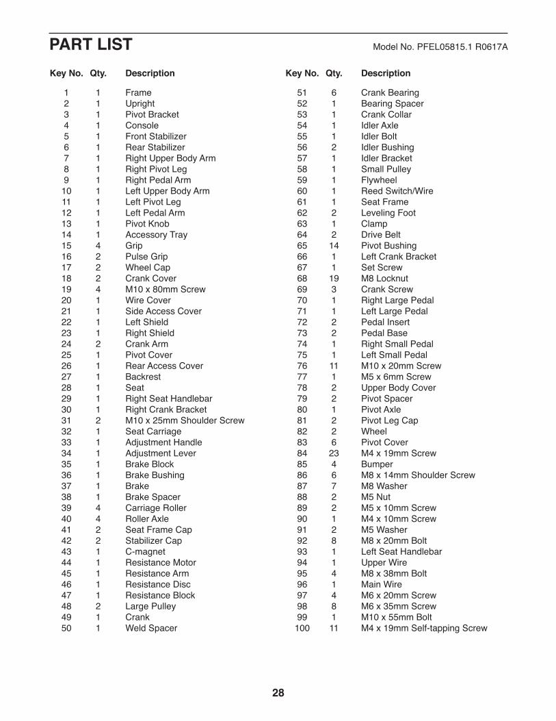
PART LIST Model No. PFEL05815.1 R0617A
1 1 Frame 2 1 Upright 3 1 Pivot Bracket 4 1 Console 5 1 Front Stabilizer 6 1 Rear Stabilizer 7 1 Right Upper Body Arm 8 1 Right Pivot Leg 9 1 Right Pedal Arm 10 1 Left Upper Body Arm 11 1 Left Pivot Leg 12 1 Left Pedal Arm 13 1 Pivot Knob 14 1 Accessory Tray 15 4 Grip 16 2 Pulse Grip 17 2 Wheel Cap 18 2 Crank Cover 19 4 M10 x 80mm Screw 20 1 Wire Cover 21 1 Side Access Cover 22 1 Left Shield 23 1 Right Shield 24 2 Crank Arm 25 1 Pivot Cover 26 1 Rear Access Cover 27 1 Backrest 28 1 Seat 29 1 Right Seat Handlebar 30 1 Right Crank Bracket 31 2 M10 x 25mm Shoulder Screw 32 1 Seat Carriage 33 1 Adjustment Handle 34 1 Adjustment Lever 35 1 Brake Block 36 1 Brake Bushing 37 1 Brake 38 1 Brake Spacer 39 4 Carriage Roller 40 4 Roller Axle 41 2 Seat Frame Cap 42 2 Stabilizer Cap 43 1 C-magnet 44 1 Resistance Motor 45 1 Resistance Arm 46 1 Resistance Disc 47 1 Resistance Block 48 2 Large Pulley 49 1 Crank 50 1 Weld Spacer
51 6 Crank Bearing 52 1 Bearing Spacer 53 1 Crank Collar 54 1 Idler Axle 55 1 Idler Bolt 56 2 Idler Bushing 57 1 Idler Bracket 58 1 Small Pulley 59 1 Flywheel 60 1 Reed Switch/Wire 61 1 Seat Frame 62 2 Leveling Foot 63 1 Clamp 64 2 Drive Belt 65 14 Pivot Bushing 66 1 Left Crank Bracket 67 1 Set Screw 68 19 M8 Locknut 69 3 Crank Screw 70 1 Right Large Pedal 71 1 Left Large Pedal 72 2 Pedal Insert 73 2 Pedal Base 74 1 Right Small Pedal 75 1 Left Small Pedal 76 11 M10 x 20mm Screw 77 1 M5 x 6mm Screw 78 2 Upper Body Cover 79 2 Pivot Spacer 80 1 Pivot Axle 81 2 Pivot Leg Cap 82 2 Wheel 83 6 Pivot Cover 84 23 M4 x 19mm Screw 85 4 Bumper 86 6 M8 x 14mm Shoulder Screw 87 7 M8 Washer 88 2 M5 Nut 89 2 M5 x 10mm Screw 90 1 M4 x 10mm Screw 91 2 M5 Washer 92 8 M8 x 20mm Bolt 93 1 Left Seat Handlebar 94 1 Upper Wire 95 4 M8 x 38mm Bolt 96 1 Main Wire 97 4 M6 x 20mm Screw 98 8 M6 x 35mm Screw 99 1 M10 x 55mm Bolt 100 11 M4 x 19mm Self-tapping Screw
Key No. Qty. Description Key No. Qty. Description
29
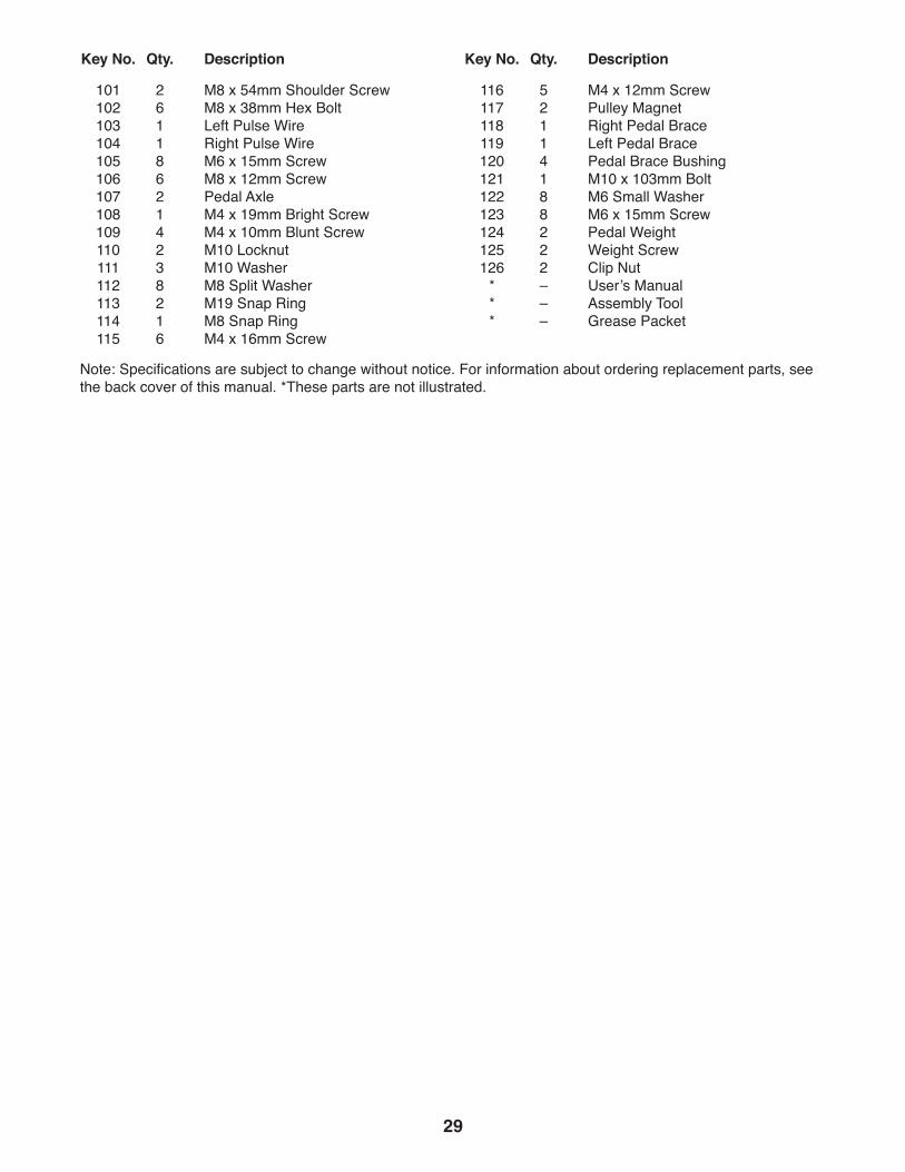
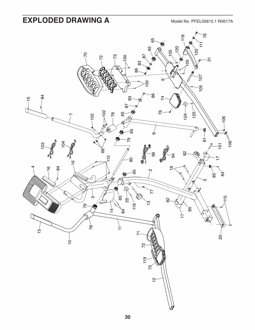
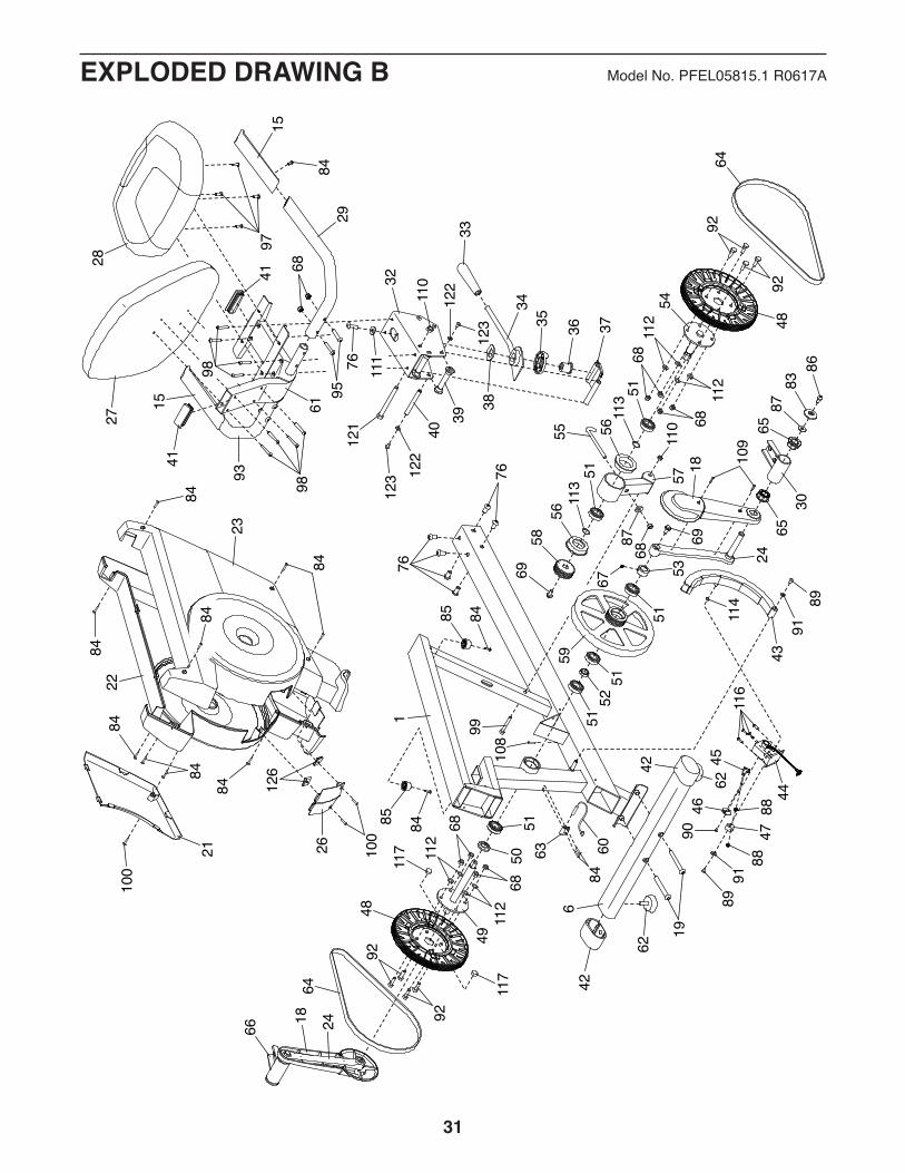
Key No. Qty. Description Key No. Qty. Description
101 2 M8 x 54mm Shoulder Screw 102 6 M8 x 38mm Hex Bolt 103 1 Left Pulse Wire 104 1 Right Pulse Wire 105 8 M6 x 15mm Screw 106 6 M8 x 12mm Screw 107 2 Pedal Axle 108 1 M4 x 19mm Bright Screw 109 4 M4 x 10mm Blunt Screw 110 2 M10 Locknut 111 3 M10 Washer 112 8 M8 Split Washer 113 2 M19 Snap Ring 114 1 M8 Snap Ring 115 6 M4 x 16mm Screw
116 5 M4 x 12mm Screw 117 2 Pulley Magnet 118 1 Right Pedal Brace 119 1 Left Pedal Brace 120 4 Pedal Brace Bushing 121 1 M10 x 103mm Bolt 122 8 M6 Small Washer 123 8 M6 x 15mm Screw 124 2 Pedal Weight 125 2 Weight Screw 126 2 Clip Nut * – User’s Manual * – Assembly Tool * – Grease Packet
Note: Specifications are subject to change without notice. For information about ordering replacement parts, see the back cover of this manual. *These parts are not illustrated.
30
EXPLODED DRAWING A Model No. PFEL05815.1 R0617A
3
8
10
12
5
2
4
7
9
11
14
16
16
19
1377
15
15
1720
70 72
7271
74
118
78
78
79
73
7511
9
80
81
83
111
83
8676
124 125
68
7631
86
85
82
120
120
8784
116
25
84
84
115
115
8410
1
100
100
105
105
105
107
102 10
2
87
106
106
65
6565
65
6565
103
104
96 94
79
85
17
82
31
EXPLODED DRAWING B Model No. PFEL05815.1 R0617A
67
69
51
1
21
23
26
28
93
32
18
18
22
24
24
27
29
15
15
34
36
38
3933
35 37
40
41
43
50
5242
42
51
51
51
59
53
60
61
63
30
66
6565
62
122
122
91
110
95
68
123
123
89
121
76 111
97
98
99
98
76
76
109
84
8484
8484
84
84
100
84 126
100
8386
87
114
116
91
9046
45
4447
8888
89684
62
19
108
56
5611
351
51
5869
55
57
8768
110
113
48
54
68
6811
2
112
6492
92
48
49
68
6811
2
112
117
64
92
92
117
41
85
85
84
84

Part No. 394363 R0617A Printed in China © 2017 ICON Health & Fitness, Inc.
To order replacement parts, please see the front cover of this manual. To help us assist you, be prepared to provide the following information when contacting us:
• the model number and serial number of the product (see the front cover of this manual)
• the name of the product (see the front cover of this manual)
• the key number and description of the replacement part(s) (see the PART LIST and the EXPLODED DRAWING near the end of this manual)
ORDERING REPLACEMENT PARTS
This electronic product must not be disposed of in municipal waste. To preserve the environment, this product must be recycled after its useful life as required by law.
Please use recycling facilities that are authorized to collect this type of waste in your area. In doing so, you will help to conserve natural resources and improve European standards of environmental protection. If you require more information about safe and correct disposal methods, please contact your local city office or the establishment where you purchased this product.
RECYCLING INFORMATION