MODEL M1021 QUICK CHANGE COLLET … Quick Change Collet Attachment 4. Thread the replacement...
20
INSTRUCTION MANUAL MODEL M1021 QUICK CHANGE COLLET ATTACHMENT Phone: (360) 734-3482 • On-Line Technical Support: [email protected] COPYRIGHT © DECEMBER, 2004 BY WOODSTOCK INTERNATIONAL, INC. WARNING: NO PORTION OF THIS MANUAL MAY BE REPRODUCED IN ANY SHAPE OR FORM WITHOUT THE WRITTEN APPROVAL OF WOODSTOCK INTERNATIONAL, INC. Printed in China #6808BL
Transcript of MODEL M1021 QUICK CHANGE COLLET … Quick Change Collet Attachment 4. Thread the replacement...

INSTRUCTION MANUAL
MODEL M1021 QUICK CHANGE
COLLET ATTACHMENT
Phone: (360) 734-3482 • On-Line Technical Support: [email protected]
COPYRIGHT © DECEMBER, 2004 BY WOODSTOCK INTERNATIONAL, INC.WARNING: NO PORTION OF THIS MANUAL MAY BE REPRODUCED IN ANY SHAPE OR FORM WITHOUT
THE WRITTEN APPROVAL OF WOODSTOCK INTERNATIONAL, INC.Printed in China#6808BL

-2-

-3-
M1021 Quick Change Collet Attachment
When ordering replacement parts, refer to the parts list and diagram in the back of the manual.
NOTICE
Inventory
Figure 1. Model M1021 inventory.
A
B
C
IdentificationThe following is a list of the major parts on the Model M1021, as shown in Figure 2:
A. Mounting Post ................................................1B. Stud ............................................................1C. Pivot Connector .............................................1D. Connecting Rod ..............................................1E. Locking Yoke .................................................1F. Handle .........................................................1G. Adjusting Hub ................................................1H. Hub Adapter .................................................1I. Draw Tube .....................................................1J. Collet Adapter ..............................................1
ABC
D
G
E
H
FI
J
Figure 2. Model M1021 identification.
The Model M1021 Quick Change Collet Attachment allows you to quickly change workpieces on your Model M1019 Gear Head Lathe. The positive-locking handle clamps standard 5-C collets safely and securely for precision turning.
The SHOP FOX® Model M1021 has been carefully pack-aged for safe transporting. If you notice the Model M1021 has been damaged, please contact your authorized SHOP FOX® dealer immediately.
The following is a description of the main components shipped with the SHOP FOX® Model M1021. Lay the components out to inventory them.
Box Contents (Figure 1) QTYA. Collet Attachment Assembly ..............................1B. Collet Adapter ...............................................1C. Handle ........................................................1
If any parts appear to be missing, examine the packag-ing carefully to be sure those parts are not among the packing materials. If any parts are missing, find the part number in the back of this manual and contact Woodstock International, Inc. at (360) 734-3482 or at [email protected]

-4-
M1021 Quick Change Collet Attachment
To begin assembly, follow these initial safety instruc-tions:
1. DISCONNECT THE LATHE FROM THE POWER SOURCE!
2. Remove the chuck or any other device that is mounted to the spindle. (Refer to your Model M1019 Gear Head Lathe owner’s manual.)
3. Make sure the 5-C Collet/Morse Taper Adapter and the spindle opening are clean and free of oil. Use a soft cloth or rag to wipe up any contaminants.
Assembly
Figure 3. Lathe cover knobs.
Disconnect power to your lathe before beginning installation of the Model M1021 Quick Change Collet Attachment.
To remove the mounting post and install the replace-ment post, do these steps:
1. Unscrew the cover knobs on the left end of the lathe to remove the end cover (see Figure 3).
2. Remove the mounting post as shown in Figure 4.
3. Remove the replacement mounting post and stud from the collet attachment assembly.
Mounting Post
Figure 4. Mounting post removal.
Mounting Post
Lathe Cover KnobsRefer to your Model M1019 Gear Head Lathe owner's
manual for proper operation of the lathe before using this tool.
-5-
M1021 Quick Change Collet Attachment
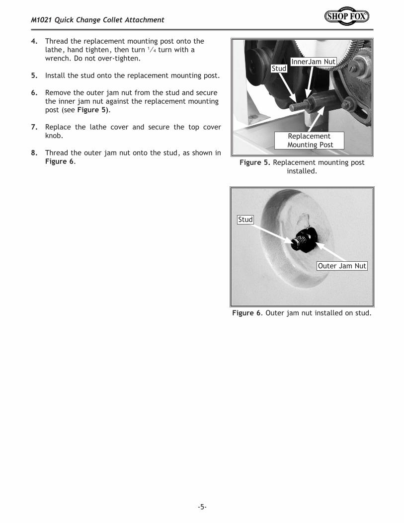
4. Thread the replacement mounting post onto the lathe, hand tighten, then turn 1⁄4 turn with a wrench. Do not over-tighten.
5. Install the stud onto the replacement mounting post.
6. Remove the outer jam nut from the stud and secure the inner jam nut against the replacement mounting post (see Figure 5).
7. Replace the lathe cover and secure the top cover knob.
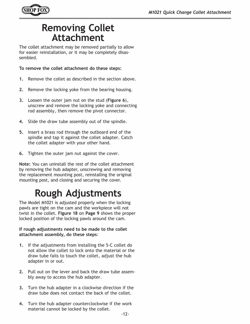
8. Thread the outer jam nut onto the stud, as shown in Figure 6.
Figure 6. Outer jam nut installed on stud.
Figure 5. Replacement mounting post installed.
Replacement Mounting Post
InnerJam NutStud
Outer Jam Nut
Stud

-6-
M1021 Quick Change Collet Attachment
Figure 9. Hub adapter installed.
Pivot Connector
To install the hub adapter to the outboard spindle, do these steps:
1. Remove the hub adapter from the draw tube assem-bly.
2. Unscrew the setscrews on the hub adapter until the screw ends are flush with or below the edge of the inside shoulder of the hub adapter, as shown in Figure 8.
3. Thread the hub adapter completely into the outboard end of the spindle (see Figure 9).
4. Secure the hub adapter to the spindle by tightening the setscrews.
To install the pivot connector, do these steps:
1. Replace the lathe cover.
2. Remove the pivot connector from the draw tube assembly, and hand thread it onto the stud (Figure 7) installed on Page 5.
3. Using a wrench, tighten the outer jam nut snug against the pivot connector.
4. The pivot pin (Figure 7) should be in a horizontal position, allowing the pivot connector to pivot up and down.
Hub AdapterFigure 7. Pivot connector.
Pivot Connector
Figure 8. Setscrews on inside shoulder of hub adapter.
Hub AdapterInside Edge
Pivot Pin
Setscrews

-7-
M1021 Quick Change Collet Attachment
Draw Tube Assembly
Figure 11. Collet in collet adapter.
Figure 10. Inserting draw tube assembly.
Draw Tube Assembly
The draw tube assembly comes attached to the locking yoke and connecting rod.
To install the draw tube assembly into your lathe, do these steps:
1. Remove the locking yoke and connecting rod from the draw tube assembly by unscrewing the setscrews that connect the locking yoke to the bearing housing.
2. Slide the draw tube assembly (Figure 10) all the way into the outboard spindle until it engages around the hub adapter.
3. Place a collet in the collet adapter, so the collet threads are exposed out of the back end of the collet adapter, as shown in Figure 11.
Figure 12. Location to rotate draw tube to remove or replace 5-C collets.
The draw tube threads may be sharp. To avoid cut-ting your hands, use a clean rag or gloves to rotate the draw tube.
4. Insert the collet and collet adapter into the draw tube on the front spindle. While holding the collet with one hand, turn the end of the draw tube (Figure 12) clockwise 5 to 8 complete revolutions with the other hand, to thread the collet onto the spindle.
5. If the collet will not thread onto the draw tube, adjust as instructed in Rough Adjustments, on Page 12.

-8-
M1021 Quick Change Collet Attachment
Figure 13. Connecting rod and locking yoke installed on pivot connector.
Locking Yoke
Locking YokeTo secure the locking yoke to your lathe, do these steps:
1. Thread the connecting rod and locking yoke onto the pivot connector, as shown in Figure 13.
2. Thread the handle onto the locking yoke and tighten
the jam nut. 3. Place the locking yoke over the draw tube assembly.
Note: If you have trouble positioning the locking yoke so it is aligned with the draw tube in the next two steps, adjust the length of the connecting rod by threading it in or out into the pivot connectors, and try again.
4. Loosen the hex nut on the locking yoke and thread the setscrews (Figure 14) into the holes on both sides of the bearing housing. Make sure the setscrews are completely and evenly engaged into the holes, with-out being tight.
5. The yoke should have no play from side-to-side, but still pivot freely. Tighten the jam nuts on the con-necting rod so they are snug against the pivot connec-tors.
6. The ideal locked position for the collet closer is shown in Figure 15. The handle should be approximately vertical.
7. If the handle is not vertical, remove the locking yoke from the bearing housing.
8. Turn the locking yoke assembly clockwise or coun-terclockwise on the pivot connector to lengthen or shorten the connecting rod.
9. Position the locking yoke back over the draw tube and check the handle position.
10. Repeat Steps 8 & 9 until the handle is close to or approximately vertical. When it is, repeat Steps 4 & 5, then go onto Main Adjustments.
Connecting Rod
Pivot Connector
Figure 14. Tightening yoke setscrews.
Figure 15. Completed collet closer assembly.
Jam Nuts

-9-
M1021 Quick Change Collet Attachment
It is essential to make the following adjustments to the collet attachment so it works properly.
To adjust the collet attachment, do these steps: 1. Insert a piece of metal stock that is sized to fit your
installed collet.
2. Disengage the hub locking pin (Figure 16) by pulling the pin out and turning it so the flat part of the pin is turned toward the outer rim of the adjusting hub. The mechanism that locks the collet is depicted in detail in Figure 17.
3. Turn the adjusting hub in or out so the collet locking pawls align properly on the flat surface of the cam lobe (see Figure 18).
4. Turn the adjusting hub clockwise until you start to feel resistance in the adjusting hub.
5. Engage the hub locking pin.
Main Adjustments
Figure 16. Hub locking pin positions.
EngagedDisengaged
��
Figure 17. Collet locking mechanism.
Figure 18. Collet locking pawls in locked position on the cam lobe.
Cam Lobe
Collet Locking Pawls
Adjusting Hub
Continued on next page

-10-
M1021 Quick Change Collet Attachment
Figure 19. Shoulder on threaded cam lobe and draw tube.
Figure 21. Hub locking pin disengaged.
Hub Locking Pin
Adjusting Hub
6. Turn the two 30mm collars clockwise on the draw tube until they contact the shoulder on the threaded portion of the cam lobe, as shown in Figures 19 & 20. Figure 19 is shown without the 30mm collars to more clearly show the cam lobe shoulder.
7. Tighten the set screw on the outer 30mm collar to ensure the locking pawls stay in place.
Note: If you do not make this adjustment, the lock-ing pawls could fall off the cam lobe when the lever is engaged. If this should happen, use a screwdriver to raise the locking pawls back onto the cam lobe.
8. Engage the lever and see if the workpiece moves.
9. To tighten the workpiece more, disengage the lever.
10. Pull the hub locking pin out (see Figure 21). While holding the pin with one hand, rotate the adjust-ing hub clockwise with your other hand until the pin engages into the next hole on the hub adapter.
Note: If the hub locking pin will not engage with the hub adapter, see the Hub Locking Pin Adjustments section on Page 11.
11. Repeat Steps 8–10 until the workpiece is tight in the
collet.
12. Push the lever toward the machine to release the workpiece. Figure 20. Inner 30mm collar nearly
touching threaded cam lobe shoulder.
Draw Tube
Cam Lobe
Shoulder
Inner 30mm Collar
Draw Tube
38mm Collar
Cam Lobe Shoulder
38mm Collar

-11-
M1021 Quick Change Collet Attachment
To remove or replace your 5-C collet in the collet attachment assembly, do these steps:
1. Disengage the hub locking pin so the flat part of the pin is turned toward the outer rim of the adjusting hub as shown in Figure 16 on Page 9.
2. To unthread the collet, rotate the draw tube coun-terclockwise, in the location shown in Figure 12.
3. Remove the current collet from the collet adapter and insert a new 5-C collet.
Removing 5-C ColletFigure 22. Hex nut and knurled knob
adjusted.
Hub Locking Pin Adjustments
If the hub locking pin will not engage with the hub adapter holes, do these steps:
1. Disengage the hub locking pin.
2. Thread the hex nut to the end of the hub locking pin.
3. Turn the knurled knob until it touches the hex nut, as shown in Figure 22 and tighten.
4. Engage the hub locking pin.
Knurled Knob
Hex NutHub
Locking Pin
4. Rotate the draw tube clockwise five to eight turns to engage the new collet threads. Engage the hub lock-ing pin back into place as shown in Figure 16.
5. Adjust the collet attachment per Steps 7–11 on Page 10 if necessary.
The draw tube threads may be sharp. To avoid cut-ting your hands, use a clean rag or gloves to rotate the draw tube.
To insert a workpiece that is thicker or thinner than the current 5-C collet capacity, you will need to remove the collet and install one that fits the new workpiece.
-12-
M1021 Quick Change Collet Attachment
Rough AdjustmentsThe Model M1021 is adjusted properly when the locking pawls are tight on the cam and the workpiece will not twist in the collet. Figure 18 on Page 9 shows the proper locked position of the locking pawls around the cam.
If rough adjustments need to be made to the collet attachment assembly, do these steps:
1. If the adjustments from installing the 5-C collet do not allow the collet to lock onto the material or the draw tube fails to touch the collet, adjust the hub adapter in or out.
2. Pull out on the lever and back the draw tube assem-bly away to access the hub adapter.
3. Turn the hub adapter in a clockwise direction if the draw tube does not contact the back of the collet.
4. Turn the hub adapter counterclockwise if the work material cannot be locked by the collet.
Removing Collet Attachment
The collet attachment may be removed partially to allow for easier reinstallation, or it may be completely disas-sembled.
To remove the collet attachment do these steps:
1. Remove the collet as described in the section above.
2. Remove the locking yoke from the bearing housing.
3. Loosen the outer jam nut on the stud (Figure 6), unscrew and remove the locking yoke and connecting rod assembly, then remove the pivot connector.
4. Slide the draw tube assembly out of the spindle.
5. Insert a brass rod through the outboard end of the spindle and tap it against the collet adapter. Catch the collet adapter with your other hand.
6. Tighten the outer jam nut against the cover.
Note: You can uninstall the rest of the collet attachment by removing the hub adapter, unscrewing and removing the replacement mounting post, reinstalling the original mounting post, and closing and securing the cover.

-13-
M1021 Quick Change Collet Attachment
The Model M1021 Quick Change Collet Attachment is essentially a maintenance free tool; however, some things to keep in mind are:
• Make sure that all the components of your collet attachment are assembled correctly, according to this manual.
• Once the replacement mounting post and hub adapt-er are installed, they will not need to be removed.
• Ensure that your locking mechanism is working prop-erly before you start any projects on your lathe.
• Check for proper placement of locking pawls on the cams.
• The bearings are non-serviceable. If you have prob-lems with your bearings, you must order a new bearing pack.
• The hub adapter must be removed in order to change gears or access V-Belts.
• Make sure threads are kept clean and oiled to pre-vent binding and rusting.
Maintenance
MAKE SURE that your machine is unplugged during all maintenance pro-cedures! If this warning is ignored, seri-ous personal injury may occur.

-14-
M1021 Quick Change Collet Attachment
12
3
4
5
6
7
8
9
1011
12
1314
15
16
17
1819
202122
23 24
25
2728
2930
31
32
33
3430
35
9
9
9
5
PARTS
-15-
M1021 Quick Change Collet Attachment
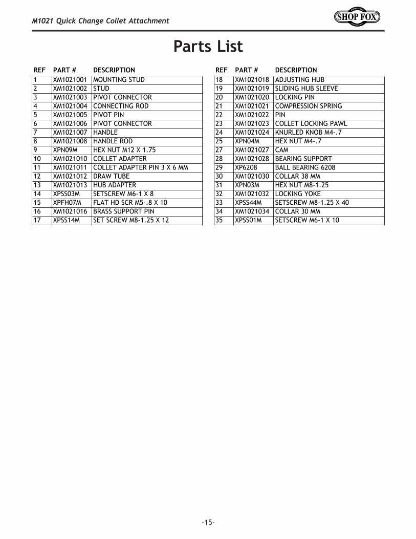
Parts ListREF PART # DESCRIPTION REF PART # DESCRIPTION1 XM1021001 MOUNTING STUD 18 XM1021018 ADJUSTING HUB2 XM1021002 STUD 19 XM1021019 SLIDING HUB SLEEVE3 XM1021003 PIVOT CONNECTOR 20 XM1021020 LOCKING PIN4 XM1021004 CONNECTING ROD 21 XM1021021 COMPRESSION SPRING 5 XM1021005 PIVOT PIN 22 XM1021022 PIN6 XM1021006 PIVOT CONNECTOR 23 XM1021023 COLLET LOCKING PAWL7 XM1021007 HANDLE 24 XM1021024 KNURLED KNOB M4-.78 XM1021008 HANDLE ROD 25 XPN04M HEX NUT M4-.79 XPN09M HEX NUT M12 X 1.75 27 XM1021027 CAM10 XM1021010 COLLET ADAPTER 28 XM1021028 BEARING SUPPORT11 XM1021011 COLLET ADAPTER PIN 3 X 6 MM 29 XP6208 BALL BEARING 620812 XM1021012 DRAW TUBE 30 XM1021030 COLLAR 38 MM13 XM1021013 HUB ADAPTER 31 XPN03M HEX NUT M8-1.2514 XPSS03M SETSCREW M6-1 X 8 32 XM1021032 LOCKING YOKE15 XPFH07M FLAT HD SCR M5-.8 X 10 33 XPSS44M SETSCREW M8-1.25 X 4016 XM1021016 BRASS SUPPORT PIN 34 XM1021034 COLLAR 30 MM17 XPSS14M SET SCREW M8-1.25 X 12 35 XPSS01M SETSCREW M6-1 X 10

-16-
M1021 Quick Change Collet Attachment
WarrantyWoodstock International, Inc. warrants all SHOP FOX® machinery to be free of defects from work-manship and materials for a period of two years from the date of original purchase by the original owner. This warranty does not apply to defects due directly or indirectly to misuse, abuse, negligence or accidents, lack of maintenance, or reimbursement of third party expenses incurred.
Woodstock International, Inc. will repair or replace, at its expense and at its option, the SHOP FOX® machine or machine part which in normal use has proven to be defective, provided that the original owner returns the product prepaid to the SHOP FOX® factory service center or authorized repair facility designated by our Bellingham, WA office, with proof of their purchase of the product within two years, and provides Woodstock International, Inc. reasonable opportunity to verify the alleged defect through inspection. If it is determined there is no defect, or that the defect resulted from causes not within the scope of Woodstock International Inc.'s warranty, then the original owner must bear the cost of storing and returning the product.
This is Woodstock International, Inc.'s sole written warranty and any and all warranties that may be implied by law, including any merchantability or fitness, for any particular purpose, are hereby limited to the duration of this written warranty. We do not warrant that SHOP FOX® machinery complies with the provisions of any law or acts. In no event shall Woodstock International, Inc.'s liability under this warranty exceed the purchase price paid for the product, and any legal actions brought against Woodstock International, Inc. shall be tried in the State of Washington, County of Whatcom. We shall in no event be liable for death, injuries to persons or property or for incidental, contingent, special or consequential damages arising from the use of our products.
Every effort has been made to ensure that all SHOP FOX® machinery meets high quality and durabil-ity standards. We reserve the right to change specifications at any time because of our commitment to continuously improve the quality of our products.