Model: G240RC/G270RC Model code: X374323111 … FUEL • Mix gasoline (octane over 95) and high...
32
OWNER'S MANUAL Thank you for using ZENOAH ENGINE. ● Please read this Owner’s Manual thoroughly before operating and use the engine correctly according to this Owner’s Manual. (For safety reasons, please contact your sales dealer before operating this engine if there is something that you do not understand.) ● This engine has been designed for the use of radio control car. Please use this engine in conjunction with the manual for radio control car or radio control equipment you are going to use. ● Any modification of the engine or any use of other applications is prohibited. ● The purchaser (user) shall bear all obligations and responsibilities stipulated by law, local ordinance and the likes. Husqvarna Zenoah Co., Ltd. shall bear no responsibility whatsoever. Model: G240RC/G270RC Model code: X374323111 (G240RC) Model code: X374326111 (G270RC) 848ER893A0 (804)
Transcript of Model: G240RC/G270RC Model code: X374323111 … FUEL • Mix gasoline (octane over 95) and high...
OWNER'S MANUAL
Thank you for using ZENOAH ENGINE.
Please read this Owner’s Manual thoroughly before operating and use theengine correctly according to this Owner’s Manual. (For safety reasons, please contact your sales dealer before operating thisengine if there is something that you do not understand.)
This engine has been designed for the use of radio control car. Please use this engine in conjunction with the manual for radio control car orradio control equipment you are going to use.
Any modification of the engine or any use of other applications is prohibited.
The purchaser (user) shall bear all obligations and responsibilities stipulatedby law, local ordinance and the likes. Husqvarna Zenoah Co., Ltd. shall bear no responsibility whatsoever.
Model: G240RC/G270RCModel code: X374323111 (G240RC)Model code: X374326111 (G270RC)
848ER893A0 (804)

2

3
SPECIFICATIONS.....................................................4SAFETY PRECAUTIONS..........................................5FUEL .........................................................................7ENGINE STARTING..................................................8OPERATION .............................................................9MAINTENANCE ......................................................10SPECIAL TOOLS ....................................................15SERVICE GUIDE ....................................................16TROUBLE SHOOTING ...........................................19PARTS LIST (G240RC)...........................................22PARTS LIST (G270RC)...........................................26WARRANTY............................................................30
CONTENTS

4
SPECIFICATIONS
Engine Type G240RC G270RC
Overall Size (L x W x H) 166 x 205 x 196mm
Weight 2.07kg
Displacement 22.5cm3 25.4cm3
Clutch Engagement 6000rpm (STD Spring)
Carburetor Type WT-813A
Spark Plug NGK CMR7H
Spark Plug Gap 0.65mm
Rotating Direction Counter-Clockwise (View From PTO)

5
SAFETY PRECAUTIONS
These safety precautions are to prevent you and those people in thevicinity from incurring harm or damage. Make sure to observe theseprecautions and constantly strive to ensure safety.
Safe use of the engine is your personal obligation and responsibility.Constantly take care to act with good judgment as you enjoy yourhobbies.
• The fuel is toxic. Do not let it get into your eyes or mouth. Store it in acool place, out of the reach of infants and children.
• Use of open flames around the fuel is strictly prohibited, because ofdanger of fire.
• To prevent burns, make sure not to touch the engine while it isoperating or immediately after it has stopped.
• Do not run the motor in poorly ventilated places. Do not breathe theexhaust, as it is a health hazard.
• Please wear clothing that facilitates your safety. Remove all scarves,

6
SAFETY PRECAUTIONS
overly long sleeves, neckties and the like. Failure to do so could resultin injury.
• When mounting the engine to a model, make sure to follow the model’soperating manual. If necessary, reinforce the engine mounting unit andthe peripheral parts.

7
FUEL
• Mix gasoline (octane over 95) and high grade 2 cycle engine oil (mixing use type;F3C grade or ISO EGC grade) at mixing ratio 25~40:1.
• The mixing ratio is according to the oil recommendation.
[ NOTE ]1) Never use any alcohol fuel or alcohol added fuel, or the rubber parts in the
carburetor and engine will be damaged.2) Gasoline is very flammable. Avoid smoking and any fires near fuel.3) To prevent all possible problems on fueling system, make sure to use the fuel filter
which has more than 300 mesh or equivalent and gasoline proof rubber pipe orequivalent.Incorrect fuel filter may cause engine trouble like fuel passage stuffing in carburetor,or piston surface scratching etc.

8
ENGINE STARTING
• Push the primer pump several times until overflown fuelflows out. (Fig.1)
• Close the choke lever, and move the throttle lever1/4~1/3 open position. (Fig.1)(Fig.2)
• Pull the starter(knob) quickly until first firing noise.(Fig.3)
• Open the choke(Fig.2), throttle idle~1/4 open• Pull the starter quickly• Operate engine for a few minutes for the warming up.
• In case of engine warm condition, choking may not benecessary.
• Over choking may cause starting difficulty due to wetspark plug. In this case change spark plug or dry it, and removefuel rest in the cylinder by pulling starter.
IMPORTANT
Choke Lever
Open
Close
Primer PumpFig.1
Throttle Lever
Fig.2
Fig.3
9
OPERATION
• This engine is already tuned up to get high power and high speed, and needs correctmaintenance to keep such high performance.
• The details for operation may be described in the separate owners manual to beissued by car manufacturer.
• Be sure to have the engine cool down for 30 seconds at idle speed after full throttlerunning.

10
MAINTENANCE
1) MAINTENANCE CHART
Before Every Every Items Action Use 25 hours 100 hours Note
Leakage, Check
Damage/Crack
Idling Speed Check/Adjust
Air-cleaner Check/Cleaning Replace if necessary
Spark Plug(gap) Check/Adjust ↑
Cylinder(barrel) Check/Cleaning ↑
Piston, Ring Check/Cleaning ↑
Muffler & Bolt Check/Cleaning ↑
Bearings Check/Cleaning ↑
Crank Shaft Check/Alignment ↑
11
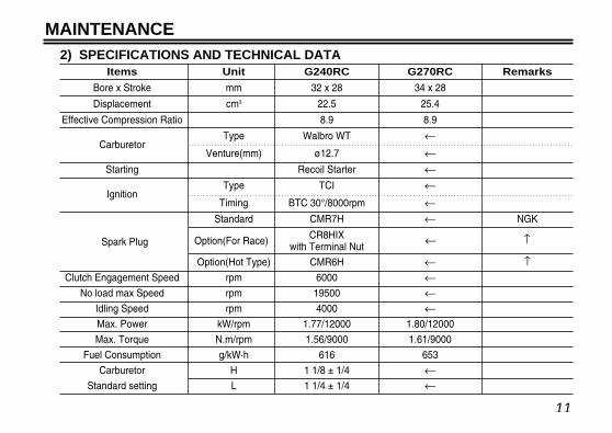
MAINTENANCE2) SPECIFICATIONS AND TECHNICAL DATA
Items Unit G240RC G270RC Remarks
Bore x Stroke mm 32 x 28 34 x 28
Displacement cm3 22.5 25.4
Effective Compression Ratio 8.9 8.9
Type Walbro WT ←Carburetor
Venture(mm) ø12.7 ←Starting Recoil Starter ←
Type TCI ←Ignition
Timing BTC 30°/8000rpm ←Standard CMR7H ← NGK
CR8HIXwith Terminal Nut
Option(Hot Type) CMR6H ← ↑Clutch Engagement Speed rpm 6000 ←
No load max Speed rpm 19500 ←Idling Speed rpm 4000 ←Max. Power kW/rpm 1.77/12000 1.80/12000
Max. Torque N.m/rpm 1.56/9000 1.61/9000
Fuel Consumption g/kW·h 616 653
Carburetor H 1 1/8 ± 1/4 ←Standard setting L 1 1/4 ± 1/4 ←
↑Option(For Race)Spark Plug ←

12
MAINTENANCE3) MAINTENANCE SPECIFICATIONS
G240RC G270RCItems Standard Limit Standard Limit Measuring Device Remarks
Bore (mm) ø32 Plating damaged ø34 Plating damaged Eye Checking
Diameter (mm) ø31.97 ø31.87 ø33.97 ø33.87 Micro Meter
Piston Ring 0.81 0.91 1.01 1.11 Thickness GaugeGroove width (mm)Piston Pin Hole (mm) ø8.01 ø8.05 ø8.01 ø8.05 Cylinder GaugeClearance between
Piston and 0.03~0.06 0.15 0.03~0.06 0.15Cylinder (mm)
Clearance betweenGroove and 0.02~0.04 0.1 0.02~0.04 0.1 Thickness Gauge
Piston Ring (mm)
End Gap (mm) 0.05~0.25 0.5 0.05~0.25 0.5 Thickness Gauge
Width (mm) 0.78 0.73 0.98 0.93 Micro MeterPiston Pin Diameter (mm) ø8 ø7.98 ø8 ø7.98 Micro Meter
Connecting Rod Small end (mm) ø11 ø11.05 ø11 ø11.05 Cylinder GaugeCrankshaft Dia. at Main Bearing (mm) ø12 ø11.98 ø12 ø11.98 Micro Meter
Eccentricity (mm) — 0.07 — 0.07 Dial GaugeAxial Play (mm) — 0.5 — 0.5 Thickness Gauge
Gritty or Gritty orMain Bearing — — —Feels Flat Spot Feels Flat Spot
At the skirt end andthe right angle tothe piston pin.
When inserted ina new cylinder.
Piston
Cylinder
Piston Ring
Micro MeterCylinder Gauge

13
MAINTENANCE
4) CARBURETOR
Items Standard Limit Measuring Device Remarks
Metering Lever set (mm) 1.65 ± 0.16 Vanier
Inlet Valve Opening Pressure (kg/cm2) 1.3~2.3 Leak Tester
Inlet Valve Closing Pressure (kg/cm2) 0.7~1.7 Leak Tester
5) IGNITION SYSTEM
Items Standard Limit Measuring Device Remarks
Spark Plug Air Gap (mm) 0.6~0.7 0.7 Thickness Gauge
Ignition Coil/Flywheel Air Gap (mm) 0.3 0.4 Thickness Gauge
Primary 0.7 — Volt Meter
Secondary 6100 — Volt Meter
Reading betweenprimary terminal andiron core.
Reading betweensparking cord end andiron core.
Coil Resistance
(Ω)

14
MAINTENANCE
6) TIGHTENING TORQUE
Items Screw Size Standard (N·m) Limit (N·m) Remarks
Carburetor M5 (P=0.8) 3.4 2.9~3.9
Insulator M5 (P=0.8) 4.4 3.9~4.9 with Locktight glue
Clutch M6 (P=1.0) 6.4 4.9~7.8
Rotor M8 (P=1.0) 12.7 9.8~14.7
Cylinder M5 (P=0.8) 6.8 4.7~8.8
Crankcase M5 (P=0.8) 6.4 4.9~7.8
Spark Plug M10 (P=1.0) 10.8 8.8~12.8
Muffler M5 (P=0.8) 8.8 6.9~9.8
Fan Cover M5 (P=0.8) 3.4 2.9~3.9
Ignition Coil M4 (P=0.7) 3.2 2.5~3.9
Starter Case M4 (P=0.7) 1.3 1.0~1.5
Tapping Screw TP 4.3 2.4 1.9~2.9

15
SPECIAL TOOLS
Part Name Part No. External Appearance Usage
1 Puller Assy 2890-96100 To remove rotor.
2 Piston Stopper 4810-96220
3 Rod Assy 1101-96220 To remove/install piston pin.
4 Air Gap Gauge 3330-97310 To set ignition coil.
5 Hex Wrench 3304-97611
6 Snap Ring Pliers 5500-96110 To remove snap ring.
To hold crankshaft whendisassembling/assemblingclutch and rotor.
For socket screw of Hex.3mm, 4mm and 5mm.

16
SERVICE GUIDE
1) REMOVING CLUTCH SHOE1. Remove the housing and plug cap.2. Remove the spark plug and fit the stopper(4810-
96220) into the plug hole.3. Remove clutch bolts(14mm Hex.).
2) REMOVING ROTOR (FAN)4. Remove the rotor nut(12mm Hex.).5. Remove the rotor using the puller assy (2890-96100).
Apply 8mm puller bolts.
Clutch Bolt(14mm Hex.)
Rotor Nut
17mm Hex.Puller Bolts
PullerRotor

17
SERVICE GUIDE
3) ASSEMBLING ROTORInsert the gauge(3330-97310) in between the rotormagnet metal and the coil.Tighten screws while pressingthe coil against the rotor.
Air Gap 0.3 ~ 0.4mm
4) REMOVING PISTON PIN1. Remove snap rings from both sides of the piston pin.2. Engage the rod assy(1101-96220) to the piston pin
and gently tap with a plastic hammer to push out thepin while holding piston firmly.
Hard hammering may damage the big end of theconnecting rod.
NOTE
Wrench
Air Gap Gauge
Ignition Coil
Plastic Hammer
Rod Assy
Piston
18
SERVICE GUIDE
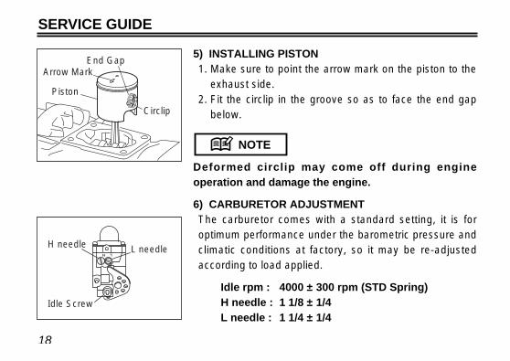
5) INSTALLING PISTON1. Make sure to point the arrow mark on the piston to the
exhaust side.2. Fit the circlip in the groove so as to face the end gap
below.
Deformed circlip may come off during engineoperation and damage the engine.
6) CARBURETOR ADJUSTMENTThe carburetor comes with a standard setting, it is foroptimum performance under the barometric pressure andclimatic conditions at factory, so it may be re-adjustedaccording to load applied.
Idle rpm : 4000 ± 300 rpm (STD Spring)H needle : 1 1/8 ± 1/4L needle : 1 1/4 ± 1/4
NOTE
Arrow Mark
Circlip
End Gap
Piston
H needle L needle
Idle Screw
19
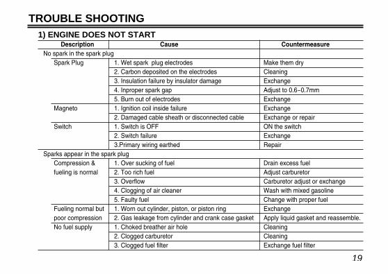
TROUBLE SHOOTING1) ENGINE DOES NOT START
Description Cause CountermeasureNo spark in the spark plug
Spark Plug 1. Wet spark plug electrodes Make them dry2. Carbon deposited on the electrodes Cleaning3. Insulation failure by insulator damage Exchange4. Inproper spark gap Adjust to 0.6~0.7mm5. Burn out of electrodes Exchange
Magneto 1. Ignition coil inside failure Exchange2. Damaged cable sheath or disconnected cable Exchange or repair
Switch 1. Switch is OFF ON the switch2. Switch failure Exchange3.Primary wiring earthed Repair
Sparks appear in the spark plugCompression & 1. Over sucking of fuel Drain excess fuelfueling is normal 2. Too rich fuel Adjust carburetor
3. Overflow Carburetor adjust or exchange4. Clogging of air cleaner Wash with mixed gasoline5. Faulty fuel Change with proper fuel
Fueling normal but 1. Worn out cylinder, piston, or piston ring Exchangepoor compression 2. Gas leakage from cylinder and crank case gasket Apply liquid gasket and reassemble.No fuel supply 1. Choked breather air hole Cleaning
2. Clogged carburetor Cleaning3. Clogged fuel filter Exchange fuel filter

20
TROUBLE SHOOTING2) LACK OF POWER OR UNSTABLE RUNNING
Description Cause Countermeasure
Compression is normal 1. Air penetration from fuel pipe joints, etc Secure connection
and no misfire 2. Air penetration from intake tube joint or Change gasket or tightening screws
carburetor joint
3. Water in fuel Change with good fuel
4. Piston start to seizure Replace piston(and cylinder)
5. Muffler choked with carbon Cleaning
Overheating 1. Fuel too lean Adjust carburetor
2. Clogging of cylinder fin with dust Cleaning
3. Poor fuel quality Exchange with proper fuel
4. Carbon deposited in the combustion chamber Cleaning
5. Spark plug electrode red hot Thoroughly clean, adjust spark gap
[ 0.6~0.7(0.023~0.028in) ]
Others 1. Dirty air cleaner Wash with mixed gasoline
2. Over loading Reduce load

21
PARTS LIST
22
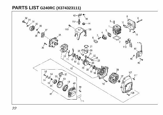
PARTS LIST G240RC (X374323111)
23
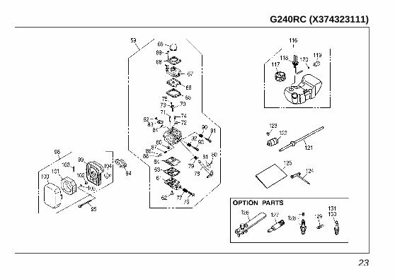
G240RC (X374323111)

24
KEY# PART NUMBER DESCRIPTION REMARKSQ'TY/UNIT
KEY# PART NUMBER DESCRIPTION REMARKSQ'TY/UNIT
35 1140-21162 CASE, CLUTCH 136 3350-15250 BOLT 4 M5x16L37 1140-55310 PLATE 138 0224-30614 BOLT 1 M6x14L39 T2070-71110 ROTOR 140 T2070-71200 COIL-A 1
42 T2075-72210 CAP 143 1400-72121 SPRING 144 5500-72130 GROMMET 145 1260-71261 SPACER 246 3350-14150 BOLT 2 M4x20L47 T2070-75101 RECOIL-A 148 T2070-75110 • CASE 149 5990-75120 • SPRING, SPIRAL 150 5990-75131 • REEL 151 5990-75141 • RATCHET 152 5990-75151 • SPRING, BREAK 153 5990-75270 • SCREW 154 5990-75160 • RETAINER 155 5990-75170 • WASHER 156 1861-75180 • ROPE 157 1490-75181 • KNOB 158 0263-90416 SCREW 4 M4x16L59 848ETZ8101 CARBURETOR-A 1 WT-813A60 3306-81380 • SCREEN 161 3080-81120 • COVER 162 3310-81130 • SCREW 163 3304-81140 • GASKET 164 1172-81150 • DIAPHRAGM 165 1751-81470 • GASKET 166 3310-81260 • DIAPHRAGM 167 T2070-81210 • BODY-A 168 1751-81520 • COVER 1
1 848ER812A0 CYLINDER 12 T2075-13120 GASKET 13 3310-12281 BOLT 4 M5x20L4 1148-13162 INSULATOR 15 848ER814B0 GASKET, INSU 16 T2075-14120 GASKET, CARB 17 3310-12281 BOLT 2 M5x20L8 T2070-15110 MUFFLER 19 01252-30550 BOLT 2 M5x50L
10 1140-13141 GASKET, MUFFLER 111 1850-32160 SCREW 1 M4x12L12 848ER82110 CRANKCASE-C 113 2629-21130 • PIN 314 5500-21141 GASKET, CASE 115 1155-21240 BEARING 216 2169-21210 SEAL 117 06034-06001 BEARING 118 04065-02812 RING 119 01252-30530 BOLT 4 M5x30L20 T2071-41110 PISTON 121 T2071-41210 RING 122 1101-41310 PIN 123 1260-41320 RING 224 5500-41410 BEARING 125 1101-41340 WASHER 226 T2070-42001 CRANKSHAFT-C 127 1650-43230 NUT 1 M8x1.028 1000-43240 KEY 129 1140-43250 SIM 130 1140-51111 SHOE 231 T2070-51220 SPRING (6000rpm IN) 132 1140-51250 SCREW 2 M6x22L33 1140-51230 WASHER 234 1140-51242 WASHER 2
PARTS LIST G240RC (X374323111)
25
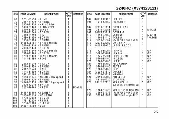
KEY# PART NUMBER DESCRIPTION REMARKSQ'TY/UNIT
KEY# PART NUMBER DESCRIPTION REMARKSQ'TY/UNIT
104 848ER883C0 • VALVE 1105 1918-82160 • WASHER 1
107 T2070-31111 COVER, FAN 1108 3310-12281 BOLT 4 M5x20L109 848ER83111 COVER-A 1110 1850-32160 SCREW 1 M4x12L111 1900-31410 SCREW 2 TP4.5x18L112 3699-91867 SPARKPLUG NGK CMR7H 1113 T2070-72200 SWITCH-A 1114 848ER890C0 LABEL, RECOIL 1
116 1726-85004 TANK-A 1 OP117 5601-85201 • CAP-A 1 OP118 1726-85601 • PIPE COMP 1 OP119 5500-85400 • FILTER 1 OP120 1260-85460 • CLIP 1 OP121 1799-85400 PIPE COMP 1122 5500-85400 FILTER 1123 1260-85460 CLIP 1124 T3039-91310 SOCKET 1125 T2070-93112 MANUAL 1126 2890-96100 PULLER-A 1 OP127 4810-96220 STOPPER 1 OP128 848ETZ7110 SPARKPLUG 1 OP
NGK CR8HIX with Terminal Nut
129 1764-51220 SPRING (5000rpm IN) 1 OP130 3699-91975 SPARKPLUG NGK CMR6H 1 OP131 3699-91809 SPARKPLUG Champion RZ7C 1 OP
69 1751-81510 • PUMP 170 2867-81270 • SPRING 171 3356-81310 • VALVE inlet 172 1480-81420 • PLUG welch 173 3310-81230 • LEVER 174 3310-81240 • SCREW 175 3310-81250 • PIN 176 2630-81330 • SCREW 177 3350-81380 • SPRING 178 848ETZ81T1 • SHAFT throttle 179 2670-81410 • SPRING 180 2880-81470 • SCREW 281 3310-81340 • VALVE throttle 182 3310-81360 • SCREW 183 1790-81440 • LEVER throttle 184 1148-81390 • RING 1
86 2812-81510 • PISTON 187 2810-81530 • SPRING 188 2812-81520 • BALL 189 1148-81530 • SCREW 490 1491-81160 • SPRING 191 1148-81171 • NEEDLE low speed 192 3080-81320 • SPRING 193 T2070-81330 • NEEDLE high speed 194 T2070-82510 SPACER 195 0263-90560 SCREW 2 M5x60L
98 848ER88300 CLEANER-A 199 T1000-82110 • HOUSING 1
100 5730-82040 • COVER 1101 1751-82020 • FILTER 1102 5730-82060 • SLEEVE 2103 848EP183Y0 • CLIP 1
G240RC (X374323111)

26
PARTS LIST G270RC (X374326111)

27
G270RC (X374326111)

28
KEY# PART NUMBER DESCRIPTION REMARKSQ'TY/UNIT
KEY# PART NUMBER DESCRIPTION REMARKSQ'TY/UNIT
35 1140-21162 CASE, CLUTCH 136 3350-15250 BOLT 4 M5x16L37 1140-55310 PLATE 138 0224-30614 BOLT 1 M6x14L39 T2070-71110 ROTOR 140 T2070-71200 COIL-A 1
42 T2075-72210 CAP 143 1400-72121 SPRING 144 5500-72130 GROMMET 145 1260-71261 SPACER 246 3350-14150 BOLT 2 M4x20L47 T2070-75101 RECOIL-A 148 T2070-75110 • CASE 149 5990-75120 • SPRING, SPIRAL 150 5990-75131 • REEL 151 5990-75141 • RATCHET 152 5990-75151 • SPRING, BREAK 153 5990-75270 • SCREW 154 5990-75160 • RETAINER 155 5990-75170 • WASHER 156 1861-75180 • ROPE 157 1490-75181 • KNOB 158 0263-90416 SCREW 4 M4x16L59 848ETZ8101 CARBURETOR-A 1 WT-813A60 3306-81380 • SCREEN 161 3080-81120 • COVER 162 3310-81130 • SCREW 163 3304-81140 • GASKET 164 1172-81150 • DIAPHRAGM 165 1751-81470 • GASKET 166 3310-81260 • DIAPHRAGM 167 T2070-81210 • BODY-A 168 1751-81520 • COVER 1
1 848ET812A0 CYLINDER 12 T2075-13120 GASKET 13 3310-12281 BOLT 4 M5x20L4 1148-13162 INSULATOR 15 848ER814B0 GASKET, INSU 16 T2075-14120 GASKET, CARB 17 3310-12281 BOLT 2 M5x20L8 T2070-15110 MUFFLER 19 01252-30550 BOLT 2 M5x50L
10 1140-13141 GASKET, MUFFLER 111 1850-32160 SCREW 1 M4x12L12 848ER82110 CRANKCASE-C 113 2629-21130 • PIN 314 5500-21141 GASKET, CASE 115 1155-21240 BEARING 216 2169-21210 SEAL 117 06034-06001 BEARING 118 04065-02812 RING 119 01252-30530 BOLT 4 M5x30L20 T2088-41110 PISTON 121 T2088-41210 RING 122 1600-41310 PIN 123 1260-41320 RING 224 5500-41410 BEARING 125 1101-41340 WASHER 226 T2070-42001 CRANKSHAFT-C 127 1650-43230 NUT 1 M8x1.028 1000-43240 KEY 129 1140-43250 SIM 130 1140-51111 SHOE 231 T2070-51220 SPRING (6000rpm IN) 132 1140-51250 SCREW 2 M6x22L33 1140-51230 WASHER 234 1140-51242 WASHER 2
PARTS LIST G270RC (X374326111)

29
KEY# PART NUMBER DESCRIPTION REMARKSQ'TY/UNIT
KEY# PART NUMBER DESCRIPTION REMARKSQ'TY/UNIT
104 848ER883C0 • VALVE 1105 1918-82160 • WASHER 1
107 T2070-31111 COVER, FAN 1108 3310-12281 BOLT 4 M5x20L109 T2070-32100 COVER-A 1110 1850-32160 SCREW 1 M4x12L111 1900-31410 SCREW 2 TP4.5x18L112 3699-91867 SPARKPLUG NGK CMR7H 1113 T2070-72200 SWITCH-A 1114 T2700-75410 LABEL, RECOIL 1
116 1726-85004 TANK-A 1 OP117 5601-85201 • CAP-A 1 OP118 1726-85601 • PIPE COMP 1 OP119 5500-85400 • FILTER 1 OP120 1260-85460 • CLIP 1 OP121 1799-85400 PIPE COMP 1122 5500-85400 FILTER 1123 1260-85460 CLIP 1124 T3039-91310 SOCKET 1125 T2070-93112 MANUAL 1126 2890-96100 PULLER-A 1 OP127 4810-96220 STOPPER 1 OP128 848ETZ7110 SPARKPLUG 1 OP
NGK CR8HIX with Terminal Nut
129 1764-51220 SPRING (5000rpm IN) 1 OP130 3699-91975 SPARKPLUGNGK CMR6H 1 OP131 3699-91809 SPARKPLUG Champion RZ7C 1 OP
69 1751-81510 • PUMP 170 2867-81270 • SPRING 171 3356-81310 • VALVE inlet 172 1480-81420 • PLUG welch 173 3310-81230 • LEVER 174 3310-81240 • SCREW 175 3310-81250 • PIN 176 2630-81330 • SCREW 177 3350-81380 • SPRING 178 848ETZ81T1 • SHAFT throttle 179 2670-81410 • SPRING 180 2880-81470 • SCREW 281 3310-81340 • VALVE throttle 182 3310-81360 • SCREW 183 1790-81440 • LEVER throttle 184 1148-81390 • RING 1
86 2812-81510 • PISTON 187 2810-81530 • SPRING 188 2812-81520 • BALL 189 1148-81530 • SCREW 490 1491-81160 • SPRING 191 1148-81171 • NEEDLE low speed 192 3080-81320 • SPRING 193 T2070-81330 • NEEDLE high speed 194 T2070-82510 SPACER 195 0263-90560 SCREW 2 M5x60L
98 848ER88300 CLEANER-A 199 T1000-82110 • HOUSING 1
100 5730-82040 • COVER 1101 1751-82020 • FILTER 1102 5730-82060 • SLEEVE 2103 848EP183Y0 • CLIP 1
G270RC (X374326111)

30
WARRANTY
WARRANTY TERMS
1) Scope of ApplicationThis engine manufactured by Husqvarna Zenoah Co., Ltd. (herein after “Zenoah”). And sold to the user directly or through distributor/manufacturer, shall entitle to becovered by this warranty.
2) Limits of WarrantyZenoah warrants that;
1. The quality disclosed in the specifications.2. The engine which shall be considered defective by Zenoah, caused by material or
production fault.
3) Limits of Compensation1. Zenoah compensates such quality, material and production faults by repairing or
replacing through distributor/manufacture.2. Zenoah shall not compensate any other accompanied or benefit losses caused to
user and distributor/manufacture by such faults and through repairing orreplacing.

31
WARRANTY
4) Term of WarrantyThree (3) months after purchased by end- user subject to 12 months from producedmonth.
5) Exempt from WarrantyZenoah shall not warrant this engine even if the fault has been caused during theperiod of terms of Warranty, in case that.
1. Any faults, failures caused from neglect of proper operation and maintenancedescribed in OWNER’S MANUAL.
2. Any modification not approved by Zenoah.3. Normal abrasion and deterioration.4. Consuming parts.5. Using any parts which have not been certified by Zenoah.6. Add-on or modified use.

Head Office : 1-9 Minamidai, Kawagoe-city, Saitama, 350-1165 JapanPhone: (+81)49-243-1115 Fax: (+81)49-243-7197