MODEL G0665 SLOW SPEED COLD CUT SAW · 7aVYZ H^oZ##### #####'%%bb ##### 6gWdg H ... 6ajb^cjb ... Vo...
40
MODEL G0665 SLOW SPEED COLD CUT SAW OWNER'S MANUAL Copyright © April, 2008 By grizzly industriAl, inC. WARNING: NO PORTION OF THIS MANUAL MAY BE REPRODUCED IN ANY SHAPE OR FORM WITHOUT THE WRITTEN APPROVAL OF GRIZZLY INDUSTRIAL, INC. #JB10523 printed in tAiWAn
Transcript of MODEL G0665 SLOW SPEED COLD CUT SAW · 7aVYZ H^oZ##### #####'%%bb ##### 6gWdg H ... 6ajb^cjb ... Vo...

MODEL G0665SLOW SPEED COLD CUT SAW
OWNER'S MANUAL
Copyright © April, 2008 By grizzly industriAl, inC.WARNiNG: NO PORTiON Of ThiS MANUAL MAy bE REPRODUCED iN ANy ShAPE
OR fORM WiThOUT ThE WRiTTEN APPROvAL Of GRizzLy iNDUSTRiAL, iNC. #JB10523 printed in tAiWAn

iNTRODUCTiON ............................................................................................................................... 2Foreword .................................................................................................................................... 2Contact info ................................................................................................................................ 2Functional overview ................................................................................................................... 2identification ............................................................................................................................... 3Machine data sheet ................................................................................................................... 4
SECTiON 1: SAfETy ....................................................................................................................... 6safety instructions for Machinery ............................................................................................... 6safety instructions for Metal Cutting saws ................................................................................ 8
SECTiON 2: CiRCUiT REQUiREMENTS ........................................................................................ 9220V single-phase..................................................................................................................... 9
SECTiON 3: SETUP ....................................................................................................................... 10setup safety ............................................................................................................................. 10items needed for setup ........................................................................................................... 10unpacking ................................................................................................................................ 10inventory ................................................................................................................................... 11Clean up .................................................................................................................................. 12site Considerations .................................................................................................................. 12Mounting to shop Floor ............................................................................................................ 13setup ........................................................................................................................................ 14test run ................................................................................................................................... 15
SECTiON 4: OPERATiONS ........................................................................................................... 16operation safety ...................................................................................................................... 16Basic Controls .......................................................................................................................... 16Cutting Angle ............................................................................................................................ 17Vise .......................................................................................................................................... 18Work stop................................................................................................................................. 20Blade Changes ......................................................................................................................... 21Cutting Fluid ............................................................................................................................. 22Cutting procedures................................................................................................................... 23Cutting tips .............................................................................................................................. 23general Machine tips .............................................................................................................. 23
SECTiON 5: ACCESSORiES ......................................................................................................... 24
SECTiON 6: MAiNTENANCE......................................................................................................... 25schedule .................................................................................................................................. 25Cleaning ................................................................................................................................... 25unpainted Cast iron ................................................................................................................. 25lubrication ................................................................................................................................ 25
SECTiON 7: SERviCE ................................................................................................................... 27troubleshooting ........................................................................................................................ 27electrical Components ............................................................................................................. 29Wiring diagram......................................................................................................................... 30parts Breakdown ...................................................................................................................... 31parts list .................................................................................................................................. 32stand Breakdown ..................................................................................................................... 33Warning labels ........................................................................................................................ 34
WARRANTy AND RETURNS ........................................................................................................ 37
Table of Contents

-2- g0665 slow speed Cold Cut saw
iNTRODUCTiON
foreword
We are proud to offer the Model g0665 slow speed Cold Cut saw. this machine is part of a growing grizzly family of fine metalworking machinery. When used according to the guide-lines set forth in this manual, you can expect years of trouble-free, enjoyable operation and proof of grizzly’s commitment to customer satis-faction.
the specifications, drawings, and photographs illustrated in this manual represent the Model g0665 when the manual was prepared. however, owing to grizzly’s policy of continuous improve-ment, changes may be made at any time with no obligation on the part of grizzly. For your conve-nience, we always keep current grizzly manuals available on our website at www.grizzly.com. Any updates to your machine will be reflected in these manuals as soon as they are complete. Visit our site often to check for the latest updates to this manual!
We stand behind our machines. if you have any service questions, parts requests or general ques-tions about the machine, please call or write us at the location listed below.
grizzly industrial, inc.1203 lycoming Mall Circle
Muncy, pA 17756phone: (570) 546-9663
Fax: (800) 438-5901e-Mail: [email protected]
if you have any comments regarding this manual, please write to us at the address below:
grizzly industrial, inc.C/o technical documentation Manager
p.o. Box 2069Bellingham, WA 98227-2069email: [email protected]
Contact info
this slow speed Cold Cut saw is used to cut metal workpieces at angles from -45° to 45° accu-rately, efficiently, and safely.
the cut is adjusted to the desired angle with the integrated scale then locked with the miter lock lever. the adjustable vise jaw is then adjusted to provide maximum support to the workpiece and sufficient clearance from the blade. the work stop can be positioned to easily produce repeatable, same-length cuts.
the workpiece is clamped in the vise using the "spinner" style vise handle. the quick release lever can be used to quickly release the workpiece, reposition it, then reclamp it with the same force without having to turn the handle several times.
once the workpiece is securely clamped, the machine is powered with the on/oFF switch and turned on by the trigger switch on the saw arm. this switch turns the motor ON, spinning the 50 rpM blade and pumping the cutting fluid onto the blade. the auto-retract blade guard protects the user from the blade and opens as the saw is lowered into the workpiece. the cutting fluid is captured in the base of the machine and returned through a screen into the cutting fluid tank.
With an even, steady pressure, the user lowers the saw into and through the workpiece. When the cut is complete, the user raises the saw, releases the trigger switch, and turns the machine OFF.
functional Overview
g0665 slow speed Cold Cut saw -3-
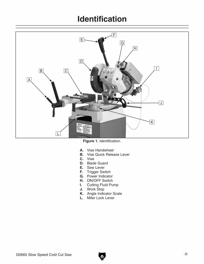
figure 1. identification.
A. Vise handwheelb. Vise Quick release leverC. ViseD. Blade guardE. saw leverf. trigger switchG. power indicatorh. on/oFF switchi. Cutting Fluid pumpJ. Work stopK. Angle indicator scaleL. Miter lock lever
identification
A
B C
d
eF
g
h
i
J
l
K
-4- g0665 slow speed Cold Cut saw
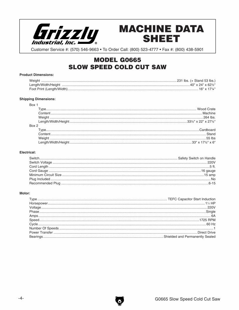
MODEL G0665SLOW SPEED COLD CUT SAW
MACHINE DATA SHEET
Product Dimensions:
Shipping Dimensions:
Electrical:
Motor:
Model G0665 Page 1 of 2
Machine Data Sheet
G0665 Slow Speed Cold Cut Saw -5-
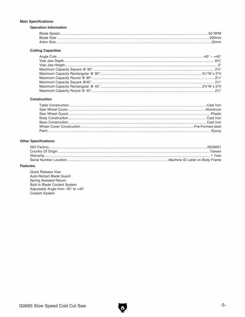
Main Specifications:
Operation Information
Cutting Capacities
Construction
Other Specifications:
Features:
Model G0665 Page 2 of 2
-6- g0665 slow speed Cold Cut saw
Safety instructions for Machinery
g0665 slow speed Cold Cut saw -7-
-8- g0665 slow speed Cold Cut saw
Safety instructions for Metal Cutting Saws8. fiRE hAzARD. use eXtreMe CAution
if cutting magnesium. using the wrong cut-ting fluid will lead to chip fire and possible explosion.
9. CUTTiNG fLUiD SAfETy. Always follow manufacturer’s cutting-fluid safety instruc-tions. pay particular attention to contact, contamination, inhalation, storage and dis-posal warnings. spilled cutting fluid invites slipping hazards.
10. ATTENTiON TO WORK AREA. never leave a machine running and unattended. pay attention to the actions of others in the area to avoid unintended accidents.
11. MAiNTENANCE/SERviCE. All inspec-tions, adjustments, and maintenance are to be done with the power OFF and the plug pulled from the outlet. Wait for all moving parts to come to a complete stop.
12. hEARiNG PROTECTiON & hAzARDS. noise generated by blade and workpiece vibration, material handling, and power transmission can cause permanent hear-ing loss over time and interfere with com-munication and audible signals.
13. hOT SURfACES. Contact with hot surfac-es from machine components, ejections of hot chips, swarf, and the workpiece itself can cause burns.
1. bLADE CONDiTiON. do not operate with dull, cracked or badly worn blade. inspect blades for cracks and missing teeth before each use.
2. hAND PLACEMENT. never position fin-gers or thumbs in line with the cut. hands could be crushed in vise or from falling machine components.
3. ENTANGLEMENT hAzARDS. do not operate this saw without blade guard in place. loose clothing, jewelry, long hair and work gloves can be drawn into working parts.
4. bLADE REPLACEMENT. When replac-ing blades, disconnect the machine from power, wear gloves to protect hands and safety glasses to protect eyes.
5. WORKPiECE hANDLiNG. Always support the workpiece with table, vise, or some type of support fixture. Flag long pieces to avoid a tripping hazard. never hold the workpiece with your hands during a cut.
6. LOSS Of STAbiLiTy. unsupported workpieces may jeopardize machine sta-bility and cause the machine to tip and fall which could cause serious injury.
7. POWER iNTERRUPTiON. unplug machine after power interruption. Machines without magnetic switches can start up after power is restored.
No list of safety guidelines can be complete. Every shop environment is different. Like all machines there is danger associated with the Model G0665. Accidents are frequently caused by lack of familiarity or failure to pay attention. Use this machine with respect and caution to lessen the possibility of operator injury. if normal safety precautions are overlooked or ignored, serious personal injury may occur.

g0665 slow speed Cold Cut saw -9-
SECTiON 2: CiRCUiT REQUiREMENTS
Extension CordsWe do not recommend the use of extension cords. instead, arrange the placement of your equipment and the installed wiring to eliminate the need for extension cords.
if you find it absolutely necessary to use an exten-sion cord at 220V with your machine:
• use at least a 16 gauge cord that does not exceed 50 feet in length!
• the extension cord must also contain a ground wire and plug pin.
• A qualified electrician Must size cords over 50 feet long to prevent motor damage.
Serious personal injury could occur if you connect the machine to the power source before you have completed the set up pro-cess. DO NOT connect the machine to the power source until instructed to do so.
220v Single-Phase Groundingin the event of an electrical short, grounding reduces the risk of electric shock. the grounding wire in the power cord must be properly connected to the grounding prong on the plug; likewise, the outlet must be properly installed and grounded. All electrical connections must be made in accor-dance with local codes and ordinances.
Amperage Drawthe Model g0665 motor draws the following amps under maximum load:
Motor draw ..............................................6 Amps
Power Supply Circuit RequirementsWe recommend connecting your machine to a dedicated and grounded circuit that is rated for the amperage given below. never replace a circuit breaker on an existing circuit with one of higher amperage without consulting a qualified electri-cian to ensure compliance with wiring codes. if you are unsure about the wiring codes in your area or you plan to connect your machine to a shared circuit, consult a qualified electrician.
Minimum Circuit size .............................15 Amps
Plug/Receptacle Typerecommended plug/receptacle ...... neMA 6-15
Electrocution or fire could result if this machine is not grounded correctly or if your electrical config-uration does not comply with all applicable codes. Ensure compliance by checking with a qualified electrician!
figure 2. neMA 6-15 plug and receptacle.

-10- g0665 slow speed Cold Cut saw
Wear safety glasses dur-ing the entire setup pro-cess!
This machine presents serious injury hazards to untrained users. Read through this entire manu-al to become familiar with the controls and opera-tions before starting the machine!
Setup Safety
SECTiON 3: SETUP
the following items are needed to complete the setup process, but are not included with your machine:
Description Qty • Assistants...........................................................3• safety glasses (For each person).................1• lifting straps (rated Min. 300 lbs.) (optional)............................................................2• power lifting equipment (rated Min. 300 lbs.) (optional)......................1• Wrench 13mm....................................................1• ratchet & socket 13mm..................................1• hex Wrench 5mm.............................................1
items Needed for Setup
your machine was carefully packaged for safe transportation. remove the packaging materials from around your machine and inspect it. if you discover the machine is damaged, please imme-diately call Customer Service at (570) 546-9663 for advice.
save the containers and all packing materials for possible inspection by the carrier or its agent. Otherwise, filing a freight claim can be difficult.
When you are completely satisfied with the condi-tion of your shipment, inventory the contents.
UnpackingThis machine and its com-ponents are very heavy. Get lifting help or use power lifting equipment such as a forklift to move heavy items.

g0665 slow speed Cold Cut saw -11-
inventory
the following is a description of the main compo-nents shipped with your machine. lay the compo-nents out to inventory them.
Note: If you can't find an item on this list, check the mounting location on the machine or examine the packaging materials carefully. Occasionally we pre-install certain components for shipping purposes.
Container 1: (figure 3) QtyA. saw............................................................. 1b. Work stop rod ........................................... 1C. Work stop ................................................... 1
Container 2: (figure 4)D. stand rear panel ....................................... 1E. stand side panels ...................................... 2f. stand Front panel ...................................... 1
hardware: (Not Shown)hex Bolts M8-1.25 x 20 (stand) ...................... 12hex nuts M8-1.25 (stand) ............................... 12hex Bolts M8-1.25 x 35 (saw Mounting) ........... 4
figure 3. Machine inventory.
if any nonproprietary parts are missing (e.g. a nut or a washer), we will gladly replace them; or for the sake of expediency, replacements can be obtained at your local hardware store.
figure 4. stand inventory.
A
BC
d e
F
-12- g0665 slow speed Cold Cut saw
floor Loadrefer to the Machine Data Sheet for the weight and footprint specifications of your machine. some residential floors may require additional reinforcement to support both the machine and operator.
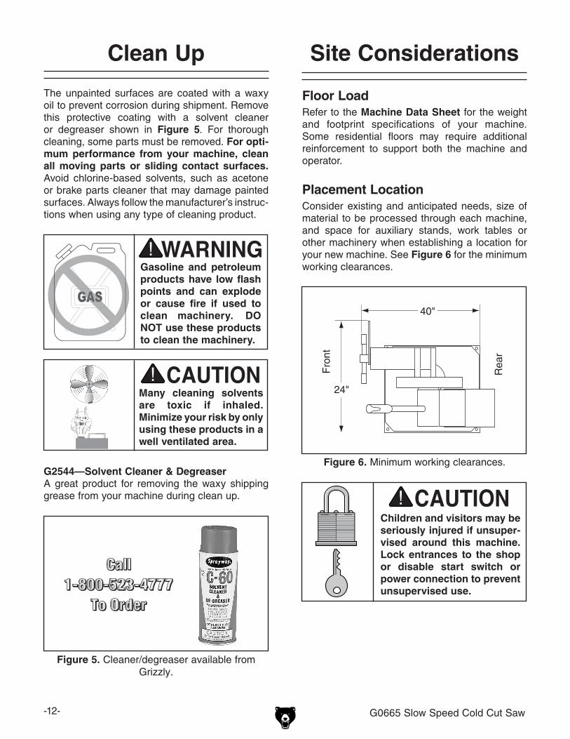
Placement LocationConsider existing and anticipated needs, size of material to be processed through each machine, and space for auxiliary stands, work tables or other machinery when establishing a location for your new machine. see figure 6 for the minimum working clearances.
Children and visitors may be seriously injured if unsuper-vised around this machine. Lock entrances to the shop or disable start switch or power connection to prevent unsupervised use.
Site Considerations
figure 6. Minimum working clearances.
40"
24"
the unpainted surfaces are coated with a waxy oil to prevent corrosion during shipment. remove this protective coating with a solvent cleaner or degreaser shown in figure 5. For thorough cleaning, some parts must be removed. for opti-mum performance from your machine, clean all moving parts or sliding contact surfaces. Avoid chlorine-based solvents, such as acetone or brake parts cleaner that may damage painted surfaces. Always follow the manufacturer’s instruc-tions when using any type of cleaning product.
Clean Up
Gasoline and petroleum products have low flash points and can explode or cause fire if used to clean machinery. DO NOT use these products to clean the machinery.
Many cleaning solvents are toxic if inhaled. Minimize your risk by only using these products in a well ventilated area.
G2544—Solvent Cleaner & DegreaserA great product for removing the waxy shipping grease from your machine during clean up.
figure 5. Cleaner/degreaser available from grizzly.
Fro
nt
rea
r

g0665 slow speed Cold Cut saw -13-
Although not required, we recommend that you mount your new machine to the floor. this will require drilling holes in the stand. Because this is an optional step and floor materials may vary, floor mounting hardware is not included.
bolting to Concrete floorslag shield anchors with lag bolts (figure 7) and anchor studs are two popular methods for anchor-ing an object to a concrete floor. We suggest you research the many options and methods for mounting your machine and choose the best that fits your specific application.
Mounting to Shop floor
NOTICEAnchor studs are stronger and more per-manent alternatives to lag shield anchors; however, they will stick out of the floor, which may cause a tripping hazard if you decide to move your machine.
figure 7. typical fasteners for mounting to concrete floors.
NOTICEWe strongly recommend securing your machine to the floor if it is hardwired to the power source. Consult with your electrician to ensure compliance with local codes.
once the stand is assembled (see Setup on Page 14) it is ready to be mounted to the shop floor.
To mount the stand to the floor:
1. drill four holes in the inner lip at the bottom of the stand in the approximate locations shown in figure 8. Be sure the holes are large enough for the anchor method you choose.
figure 8. Mounting hole locations.
2. place the stand in the desired location.
3. reach into the stand from above and mark the position of the four holes you drilled in Step 1 onto the shop floor.
4. Move the stand, then install mounting hard-ware into the floor using the method that best fits your specific application.
5. place the stand over the mounting hardware, and secure it according to the mounting hard-ware manufacturer's specifications.
Anchor stud
lag shield Anchor
lag Bolt
-14- g0665 slow speed Cold Cut saw
Setup
setup consists of assembling the stand, mounting the machine to the stand, and attaching the work stop.
To assemble the machine:
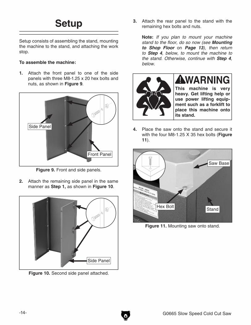
1. Attach the front panel to one of the side panels with three M8-1.25 x 20 hex bolts and nuts, as shown in figure 9.
3. Attach the rear panel to the stand with the remaining hex bolts and nuts.
Note: If you plan to mount your machine stand to the floor, do so now (see Mounting to Shop Floor on Page 13), then return to Step 4, below, to mount the machine to the stand. Otherwise, continue with Step 4, below.
figure 9. Front and side panels.
2. Attach the remaining side panel in the same manner as Step 1, as shown in figure 10.
figure 10. second side panel attached.
Front panel
side panel
side panel
4. place the saw onto the stand and secure it with the four M8-1.25 X 35 hex bolts (figure 11).
This machine is very heavy. Get lifting help or use power lifting equip-ment such as a forklift to place this machine onto its stand.
figure 11. Mounting saw onto stand.
saw Base
standhex Bolt
g0665 slow speed Cold Cut saw -15-
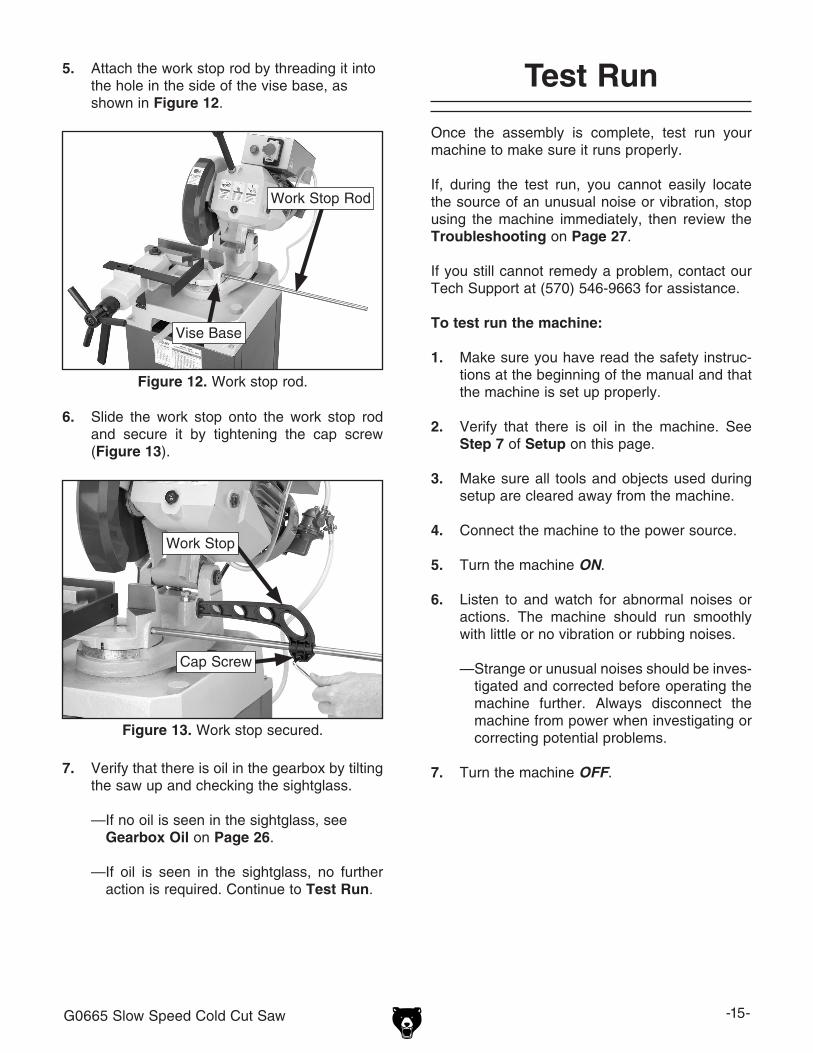
5. Attach the work stop rod by threading it into the hole in the side of the vise base, as shown in figure 12.
Test Run
once the assembly is complete, test run your machine to make sure it runs properly.
if, during the test run, you cannot easily locate the source of an unusual noise or vibration, stop using the machine immediately, then review the Troubleshooting on Page 27.
if you still cannot remedy a problem, contact our tech support at (570) 546-9663 for assistance.
To test run the machine:
1. Make sure you have read the safety instruc-tions at the beginning of the manual and that the machine is set up properly.
2. Verify that there is oil in the machine. see Step 7 of Setup on this page.
3. Make sure all tools and objects used during setup are cleared away from the machine.
4. Connect the machine to the power source.
5. turn the machine ON.
6. listen to and watch for abnormal noises or actions. the machine should run smoothly with little or no vibration or rubbing noises.
— strange or unusual noises should be inves-tigated and corrected before operating the machine further. Always disconnect the machine from power when investigating or correcting potential problems.
7. turn the machine OFF.
figure 12. Work stop rod.
6. slide the work stop onto the work stop rod and secure it by tightening the cap screw (figure 13).
figure 13. Work stop secured.
Vise Base
Work stop rod
Work stop
Cap screw
7. Verify that there is oil in the gearbox by tilting the saw up and checking the sightglass.
—if no oil is seen in the sightglass, see Gearbox Oil on Page 26.
—if oil is seen in the sightglass, no further action is required. Continue to Test Run.
-16- g0665 slow speed Cold Cut saw
SECTiON 4: OPERATiONS
Damage to your eyes and lungs could result from using this machine without proper pro-tective gear. Always wear safety glasses and a respirator when operating this machine.
Loose hair and cloth-ing could get caught in machinery and cause seri-ous personal injury. Keep loose clothing and long hair away from moving machinery.
NOTICEif you have never used this type of machine or equipment before, WE STRONGLy REC-OMMEND that you read books, trade maga-zines, or get formal training before begin-ning any projects. Regardless of the con-tent in this section, Grizzly industrial will not be held liable for accidents caused by lack of training.
Operation Safety basic Controls
use the descriptions and figures below to become familiar with the basic controls of your machine.
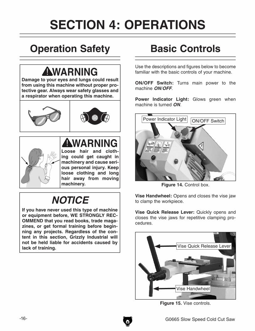
ON/Off Switch: turns main power to the machine ON/OFF.
Power indicator Light: glows green when machine is turned ON.
figure 14. Control box.
vise handwheel: opens and closes the vise jaw to clamp the workpiece.
vise Quick Release Lever: Quickly opens and closes the vise jaws for repetitive clamping pro-cedures.
figure 15. Vise controls.
power indicator light on/oFF switch
Vise handwheel
Vise Quick release lever

g0665 slow speed Cold Cut saw -17-
To set the cutting angle:
1. disConneCt sAW FroM poWer!
2. Move the miter lock lever to the left to release the saw pivot (figure 18).
figure 18. Miter lock lever.
3. rotate the saw to the desired angle using the scale as a guide. When the desired angle is reached, lock the saw in position by moving the lever to the right.
4. test the blade clearance by lowering the saw. if necessary, move the adjustable vise jaw and the auxiliary stability bracket to pro-vide adequate clearance, as outlined in vise on Page 18.
5. return the saw to the upright position.
Cutting AngleSaw Lever: lowers the saw into the workpiece.
Trigger Switch: turns the motor ON, spinning the blade and activating the cutting fluid pump.
Miter Lock Lever: releases or locks rotation of the saw base for angled cuts.
Work Stop: set at a particular distance from the blade to produce multiple same-length cuts.
figure 16. saw controls.
figure 17. Cutting fluid reservoir.
Cutting fluid Reservoir: holds cutting fluid and can be removed for disposal and cleaning.
saw lever trigger switch
Miter lock lever
Cutting Fluid reservoir
Miter lock lever
-18- g0665 slow speed Cold Cut saw
Adjustable vise Jawthe vise jaw on the Model g0665 can be adjusted for maximum support while still providing clear-ance at a variety of cutting angles. the Model g0665 also features an auxiliary stability bracket for additional support during cutting procedures.
Tools Needed: Qtyhex Wrench 10mm ............................................ 1
vise
6. tighten the cap screw.
7. return to Step 3 and re-check for clearance.
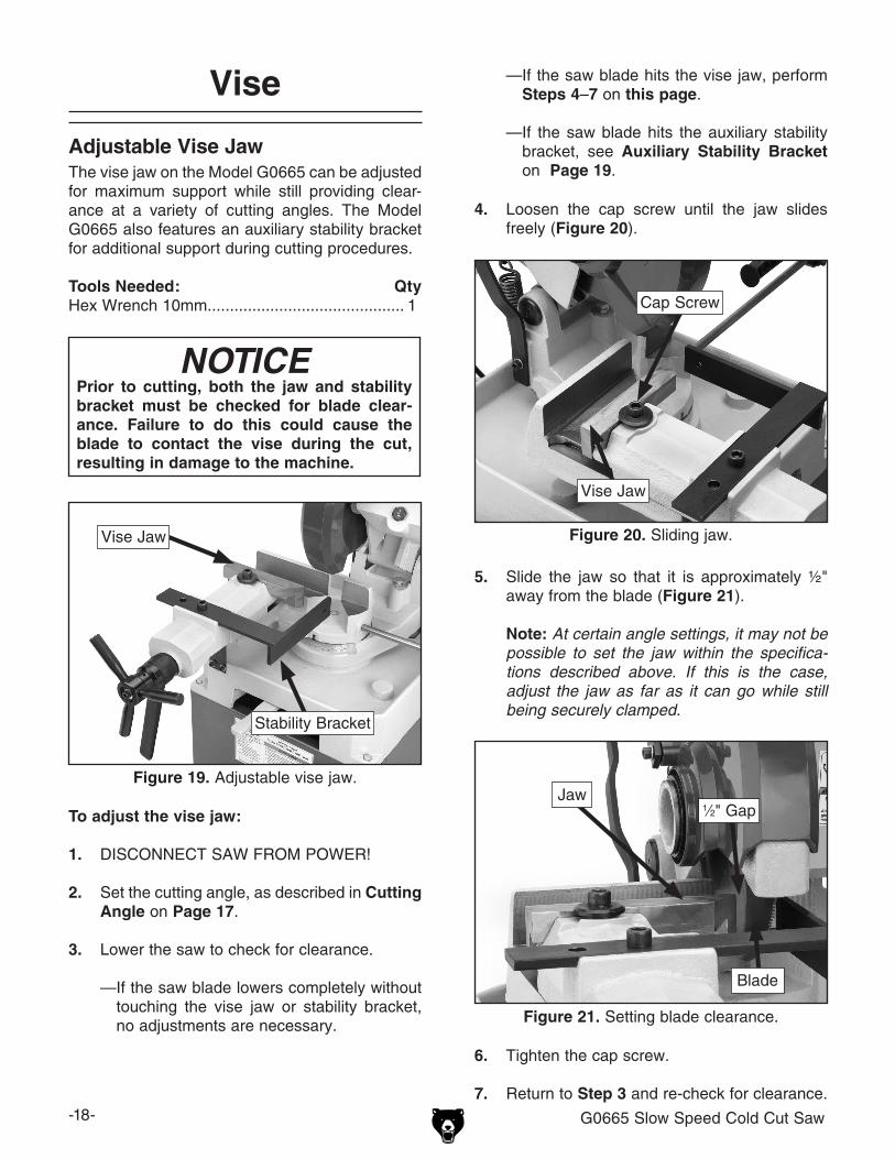
4. loosen the cap screw until the jaw slides freely (figure 20).
figure 20. sliding jaw.
5. slide the jaw so that it is approximately ½" away from the blade (figure 21).
Note: At certain angle settings, it may not be possible to set the jaw within the specifica-tions described above. If this is the case, adjust the jaw as far as it can go while still being securely clamped.
Cap screw
Vise Jaw
figure 21. setting blade clearance.
Jaw1⁄2" gap
Blade
To adjust the vise jaw:
1. disConneCt sAW FroM poWer!
2. set the cutting angle, as described in Cutting Angle on Page 17.
3. lower the saw to check for clearance.
—if the saw blade lowers completely without touching the vise jaw or stability bracket, no adjustments are necessary.
figure 19. Adjustable vise jaw.
Vise Jaw
NOTICEPrior to cutting, both the jaw and stability bracket must be checked for blade clear-ance. failure to do this could cause the blade to contact the vise during the cut, resulting in damage to the machine.
—if the saw blade hits the vise jaw, perform Steps 4–7 on this page.
—if the saw blade hits the auxiliary stability bracket, see Auxiliary Stability bracket on Page 19.
stability Bracket
g0665 slow speed Cold Cut saw -19-
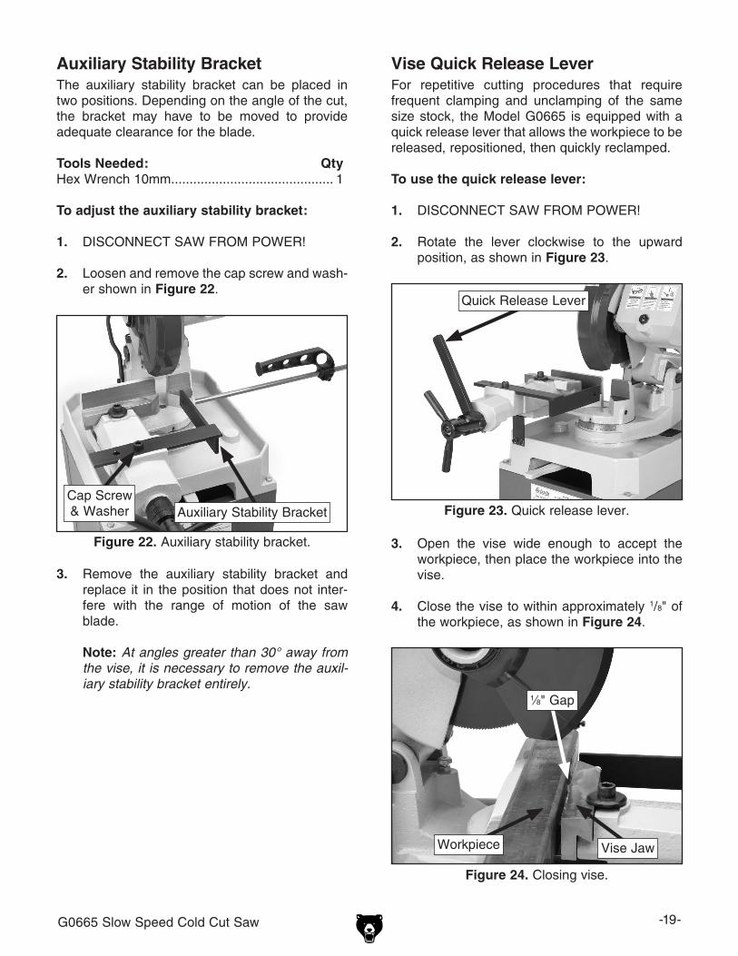
Auxiliary Stability bracketthe auxiliary stability bracket can be placed in two positions. depending on the angle of the cut, the bracket may have to be moved to provide adequate clearance for the blade.
Tools Needed: Qtyhex Wrench 10mm ............................................ 1
To adjust the auxiliary stability bracket:
1. disConneCt sAW FroM poWer!
2. loosen and remove the cap screw and wash-er shown in figure 22.
figure 22. Auxiliary stability bracket.
3. remove the auxiliary stability bracket and replace it in the position that does not inter-fere with the range of motion of the saw blade.
Note: At angles greater than 30° away from the vise, it is necessary to remove the auxil-iary stability bracket entirely.
vise Quick Release LeverFor repetitive cutting procedures that require frequent clamping and unclamping of the same size stock, the Model g0665 is equipped with a quick release lever that allows the workpiece to be released, repositioned, then quickly reclamped.
To use the quick release lever:
1. disConneCt sAW FroM poWer!
2. rotate the lever clockwise to the upward position, as shown in figure 23.
figure 23. Quick release lever.
3. open the vise wide enough to accept the workpiece, then place the workpiece into the vise.
4. Close the vise to within approximately 1/8" of the workpiece, as shown in figure 24.
figure 24. Closing vise.
Cap screw & Washer
Quick release lever
1⁄8" gap
Vise JawWorkpiece
Auxiliary stability Bracket

-20- g0665 slow speed Cold Cut saw
5. rotate the quick release lever counterclock-wise to clamp the workpiece. Between cuts, rotate the lever clockwise to release the workpiece, then counterclockwise again to reclamp it (figure 25).
figure 25. Quick release lever positions.
Work Stop
use the work stop to perform consistent length cuts.
Tools Needed: Qtyhex Wrench 5mm .............................................. 1
To use the work stop:
1. disConneCt sAW FroM poWer!
2. loosen the work stop cap screw (figure 26).
Note: An alternative method for using the quick release lever is to rotate the lever downward prior to clamping the workpiece. With the lever in this position, fully clamp the workpiece using the vise handwheel. To release the workpiece, rotate the lever clockwise to the up position. The method you practice is a matter of personal preference.
Clamped
released
3. lower the blade as far as it will go.
4. Measure from the side of the blade to the work stop. slide the work stop until the dis-tance between the blade and the work stop is equal to the desired length of the piece being cut, then tighten the cap screw (figure 27).
5. Before making a cut, slide the stock until it is against the work stop. Clamp the workpiece in the vise, then proceed with the cut. repeat this process before each new cut for consis-tent length cuts.
figure 27. Measuring length of cut.
Blade
tape Measure
Work stop
figure 26. Work stop adjustment.
Work stop
Cap screw

g0665 slow speed Cold Cut saw -21-
blade Changes 4. remove the arbor cap screw. it has left-hand threads and loosens when turned clockwise. (see figure 29).
5. remove the blade and blade flange (figure 28).
figure 30. Blade removed.
6. place the blade flange on the new blade, as shown in figure 31.
figure 31. installing new blade.
The teeth of saw blades are sharp and can easily cut fingers and hands. Always wear heavy leath-er gloves when handling saw blades.
To replace the blade:
1. disConneCt sAW FroM poWer!
2. disconnect the blade guard linkage by remov-ing the cap screw that connects it to the saw guard (figure 28).
3. rotate the blade guard and linkage out of the way, as shown in figure 29.
figure 29. exposing blade.
figure 28. removing guard linkage.
Cap screw
Blade guard
linkage
Blade guard
linkage
Blade FlangeBlade
Blade Flange
Blade
Arbor Cap screw
-22- G0665 Slow Speed Cold Cut Saw
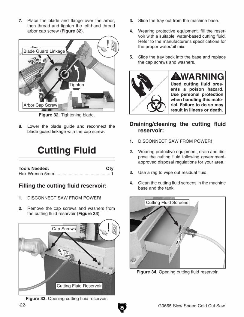
7. Place the blade and flange over the arbor, then thread and tighten the left-hand thread arbor cap screw (Figure 32).
Figure 32. Tightening blade.
8. Lower the blade guide and reconnect the blade guard linkage with the cap screw.
Cutting Fluid
Tools Needed: QtyHex Wrench 5mm .............................................. 1
Filling the cutting fluid reservoir:
1. DISCONNECT SAW FROM POWER!
2. Remove the cap screws and washers from the cutting fluid reservoir (Figure 33).
Draining/cleaning the cutting fluid reservoir:
1. DISCONNECT SAW FROM POWER!
2. Wearing protective equipment, drain and dis-pose the cutting fluid following government-approved disposal regulations for your area.
3. Use a rag to wipe out residual fluid.
4. Clean the cutting fluid screens in the machine base and the tank.
Used cutting fluid pres-ents a poison hazard. Use personal protection when handling this mate-rial. Failure to do so may result in illness or death.
3. Slide the tray out from the machine base.
4. Wearing protective equipment, fill the reser-voir with a suitable, water-based cutting fluid. Refer to the manufacturer's specifications for the proper water/oil mix.
5. Slide the tray back into the base and replace the cap screws and washers.
Arbor Cap Screw
Blade Guard Linkage
Tighten
Figure 33. Opening cutting fluid reservoir.
Cap Screws
Cutting Fluid Reservoir
Figure 34. Opening cutting fluid reservoir.
Cutting Fluid Screens
g0665 slow speed Cold Cut saw -23-
Cutting Procedures
After familiarizing yourself with the controls of the Model g0665, follow the basic outline below to perform safe and efficient cuts.
To make a cut:
1. disConneCt sAW FroM poWer!
2. set the cutting angle (Page 17).
3. Check the blade clearance (Page 18).
4. set the work stop if required for the task being performed (Page 20).
5. Clamp the workpiece (Page 18).
6. Check the cutting fluid reservoir level.
7. Make sure the saw is in the fully upright posi-tion.
8. Connect the saw to power.
9. press the trigger switch to start the blade and cutting fluid pump. once the cutting fluid is observed on the blade, lower the saw into the workpiece. use a controlled, steady force to complete the cut. When the cut is completed, raise the saw, release the trigger, and allow the blade to come to a complete stop before proceeding.
Cutting Tips
• replace, sharpen, and clean blades as nec-essary to maintain optimum cutting perfor-mance.
• use even pressure while cutting. heavy or irregular pressure can lead to poor cuts and damage the blade.
• Misusing the saw or using incorrect tech-niques is unsafe and results in poor cuts. remember—the blade does the cutting with the operator's guidance.
• When the machine is not in use, raise the saw to reduce strain on the return spring.
• inspect the machine regularly to keep it run-ning in top condition.
• Clean, lubricate, and cover the machine before putting it into storage for extended periods of time.
General Machine Tips

-24- G0665 Slow Speed Cold Cut Saw
T10060—Replacement blade for G0665 Made in Italy.
Figure 35. Replacement blade for G0665.
SECTION 5: ACCESSORIESACCESSORIES
G8983—Tilting Roller StandAdjusts from 26" to 44", 0º-45º. 150 lb. capacity.G8984—Single Roller StandAdjusts from 26 5⁄8" to 45". 250 lb. capacity.G8985—5 Roller StandAdjusts from 26" to 445⁄8". 250 lb. capacity.These super heavy-duty roller stands feature con-venient hand knobs for fast height adjustment.
Figure 36. SHOP FOX® Roller Stands.
G8983
G8984
G8985
T20501—Face Shield Crown Protector 4"T20502—Face Shield Crown Protector 7"T20503—Face Shield WindowT20452—"Kirova" Anti-Reflective S. GlassesT20451—"Kirova" Clear Safety GlassesH0736—Shop Fox® Safety GlassesH7194—Bifocal Safety Glasses 1.5H7195—Bifocal Safety Glasses 2.0H7196—Bifocal Safety Glasses 2.5
Figure 37. Eye protection assortment.
T20451
H0736
T20452T20502
T20503
H7194
H9240 Rustlick WS5050 Heavy-Duty Soluble Oil, 1 GallonEffective chlorinated E.P. additive provides excel-lent tool life. Protects neoprene seals. For gen-eral purpose and heavy-duty applications. Can be used on all metals except titanium. Compatible with CNC machining.
g0665 slow speed Cold Cut saw -25-
SECTiON 6: MAiNTENANCE
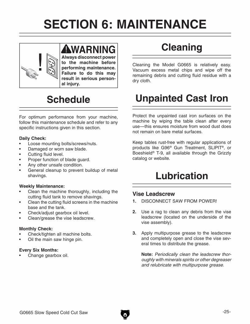
Always disconnect power to the machine before performing maintenance. failure to do this may result in serious person-al injury.
For optimum performance from your machine, follow this maintenance schedule and refer to any specific instructions given in this section.
Daily Check:• loose mounting bolts/screws/nuts.• damaged or worn saw blade.• Cutting fluid level.• proper function of blade guard.• Any other unsafe condition.• general cleanup to prevent buildup of metal
shavings.
Weekly Maintenance:• Clean the machine thoroughly, including the
cutting fluid tank to remove shavings. • Clean the cutting fluid screens in the machine
base and the tank.• Check/adjust gearbox oil level.• Clean/grease the vise leadscrew.
Monthly Check:• Check/tighten all machine bolts. • oil the main saw hinge pin.
Every Six Months:• Change gearbox oil.
Schedule
Cleaning the Model g0665 is relatively easy. Vacuum excess metal chips and wipe off the remaining debris and cutting fluid residue with a dry cloth.
Cleaning
protect the unpainted cast iron surfaces on the machine by wiping the table clean after every use—this ensures moisture from wood dust does not remain on bare metal surfaces.
Keep tables rust-free with regular applications of products like g96® gun treatment, slipit®, or Boeshield® t-9, all available through the grizzly catalog or website.
Unpainted Cast iron
vise Leadscrew1. disConneCt sAW FroM poWer!
2. use a rag to clean any debris from the vise leadscrew (located on the underside of the vise assembly).
3. Apply multipurpose grease to the leadscrew and completely open and close the vise sev-eral times to distribute the grease.
Note: Periodically clean the leadscrew thor-oughly with minerals spirits or other degreaser and relubricate with multipurpose grease.
Lubrication
-26- g0665 slow speed Cold Cut saw
Gearbox OilWith regular use, the oil in the gearbox must be drained and replaced every six months.
Tools Needed QtyWrench 7⁄8" ......................................................... 1drain pan .......................................................... 1Funnel ................................................................ 1
To change the gearbox oil:
1. disConneCt sAW FroM poWer!
2. raise the saw to the up-most position.
3. remove the oil fill/drain plug (figure 39).
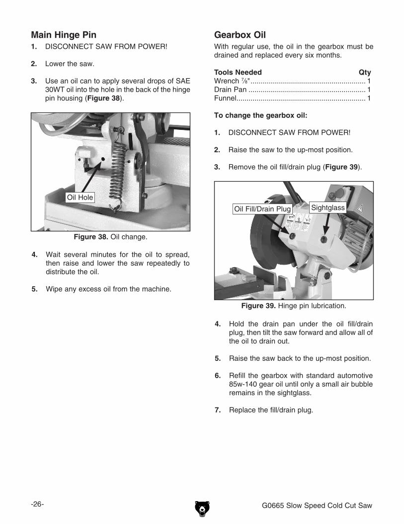
Main hinge Pin1. disConneCt sAW FroM poWer!
2. lower the saw.
3. use an oil can to apply several drops of sAe 30Wt oil into the hole in the back of the hinge pin housing (figure 38).
figure 38. oil change.
4. Wait several minutes for the oil to spread, then raise and lower the saw repeatedly to distribute the oil.
5. Wipe any excess oil from the machine.
oil hole
4. hold the drain pan under the oil fill/drain plug, then tilt the saw forward and allow all of the oil to drain out.
5. raise the saw back to the up-most position.
6. refill the gearbox with standard automotive 85w-140 gear oil until only a small air bubble remains in the sightglass.
7. replace the fill/drain plug.
figure 39. hinge pin lubrication.
oil Fill/drain plug sightglass

g0665 slow speed Cold Cut saw -27-
review the troubleshooting and procedures in this section to fix or adjust your machine if a problem devel-ops. if you need replacement parts or you are unsure of your repair skills, then feel free to call our technical support at (570) 546-9663.
SECTiON 7: SERviCE
Troubleshooting
Motor & Electrical
symptom possible Cause possible solutionMachine does not start/indica-tor light does not come on or a breaker trips.
1. switch cover not not open.2. plug/receptacle is at fault or wired incorrectly.3. Wall fuse/circuit breaker is blown/tripped.
4. indicator light has failed.5. Control box fuse/s blown.6. power supply switched oFF or is at fault.
7. Wiring is open/has high resistance.
8. Motor on/oFF switch is at fault.9. Motor is at fault.
1. reset swtich by opening cover.2. test for good contacts; correct the wiring.3. ensure circuit size is suitable for this machine;
replace weak breaker.4. replace light.5. Check l1 & l2 fuses in control box.6. ensure power supply is switched ON; ensure power
supply has the correct voltage.7. Check for broken wires or disconnected/corroded
connections, and repair/replace as necessary. 8. replace faulty on/oFF switch.9. test/repair/replace.
Machine stalls or is overloaded.
1. Feed pressure too great for task.2. Motor connection is wired incorrectly.3. plug/receptacle is at fault.4. Motor is at fault.
1. decrease feed pressure.2. Correct motor wiring connections.3. test for good contacts; correct the wiring.4. test/repair/replace.
Machine has vibration or noisy operation.
1. Motor or component is loose.
2. Motor mount loose/broken.3. Machine is incorrectly mounted or sits uneven-
ly.4 Motor fan is rubbing on fan cover.
5. Motor bearings are at fault.
1. inspect/replace stripped or damaged bolts/nuts, and re-tighten with thread locking fluid.
2. tighten/replace.3. tighten/replace anchor studs in floor; relocate/shim
machine.4. replace dented fan cover; replace loose/damaged
fan.5. test by rotating shaft; rotational grinding/loose shaft
requires bearing replacement.
indicator light is on and trigger switch fails to activate motor.
1. plug connecting switch to control box is unplugged.
2. trigger switch at fault.3. Motor is at fault.
1. Correctly insert plug.
2. test/repair/replace.3. test/repair/replace.
-28- g0665 slow speed Cold Cut saw
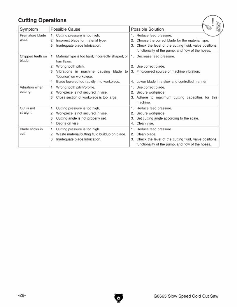
symptom possible Cause possible solutionpremature blade wear.
1. Cutting pressure is too high.2. incorrect blade for material type.3. inadequate blade lubrication.
1. reduce feed pressure.2. Choose the correct blade for the material type.3. Check the level of the cutting fluid, valve positions,
functionality of the pump, and flow of the hoses.
Chipped teeth on blade.
1. Material type is too hard, incorrectly shaped, or has flaws.
2. Wrong tooth pitch.3. Vibrations in machine causing blade to
"bounce" on workpiece.4. Blade lowered too rapidly into workpiece.
1. decrease feed pressure.
2. use correct blade.3. Find/correct source of machine vibration.
4. lower blade in a slow and controlled manner.
Vibration when cutting.
1. Wrong tooth pitch/profile.2. Workpiece is not secured in vise.3. Cross section of workpiece is too large.
1. use correct blade.2. secure workpiece.3. Adhere to maximum cutting capacities for this
machine.
Cut is not straight.
1. Cutting pressure is too high.2. Workpiece is not secured in vise.3. Cutting angle is not properly set.4. debris on vise.
1. reduce feed pressure.2. secure workpiece.3. set cutting angle according to the scale.4. Clean vise.
Blade sticks in cut.
1. Cutting pressure is too high.2. Waste material/cutting fluid buildup on blade.3. inadequate blade lubrication.
1. reduce feed pressure.2. Clean blade.3. Check the level of the cutting fluid, valve positions,
functionality of the pump, and flow of the hoses.
Cutting Operations

g0665 slow speed Cold Cut saw -29-
Electrical Components
figure 40. g0665 electrical components.
Contactor
transformer
overload relay
on/oFF switch
15AFuses
start Capacitor
indicator light

-30- g0665 slow speed Cold Cut saw
View this page in color at www.grizzly.com.
WARNING!SHOCK HAZARD!Disconnect powerbefore working onwiring.
The motor wiring shown here is current at the time of printing, but it may not match your machine. Always use the wiring diagram inside the motor junction box.
220 VAC6-15 Plug
(As Recommended)
TC 11
Wiring Diagram
g0665 slow speed Cold Cut saw -31-
1
2
345
6
7
8
8-18-2
8-38-4
8-5
10
11
1213 14
14
15
17
1819 20
21 29 30
31
3131
3133
3435
36 37
37
38
39
4041
42
101-1
101-4
102
103
101-3
101-12
101-13
101-2101-5
101-6
101-11
101-10101-9
101-8
101-7
101
43
44
45
4647
474849
5051
52
53545556
5758
5859
60
6162
6364
6566
67 68
79
82
8586
86-186-2
8788
89
90
91
9293 94
9798
100
101-14
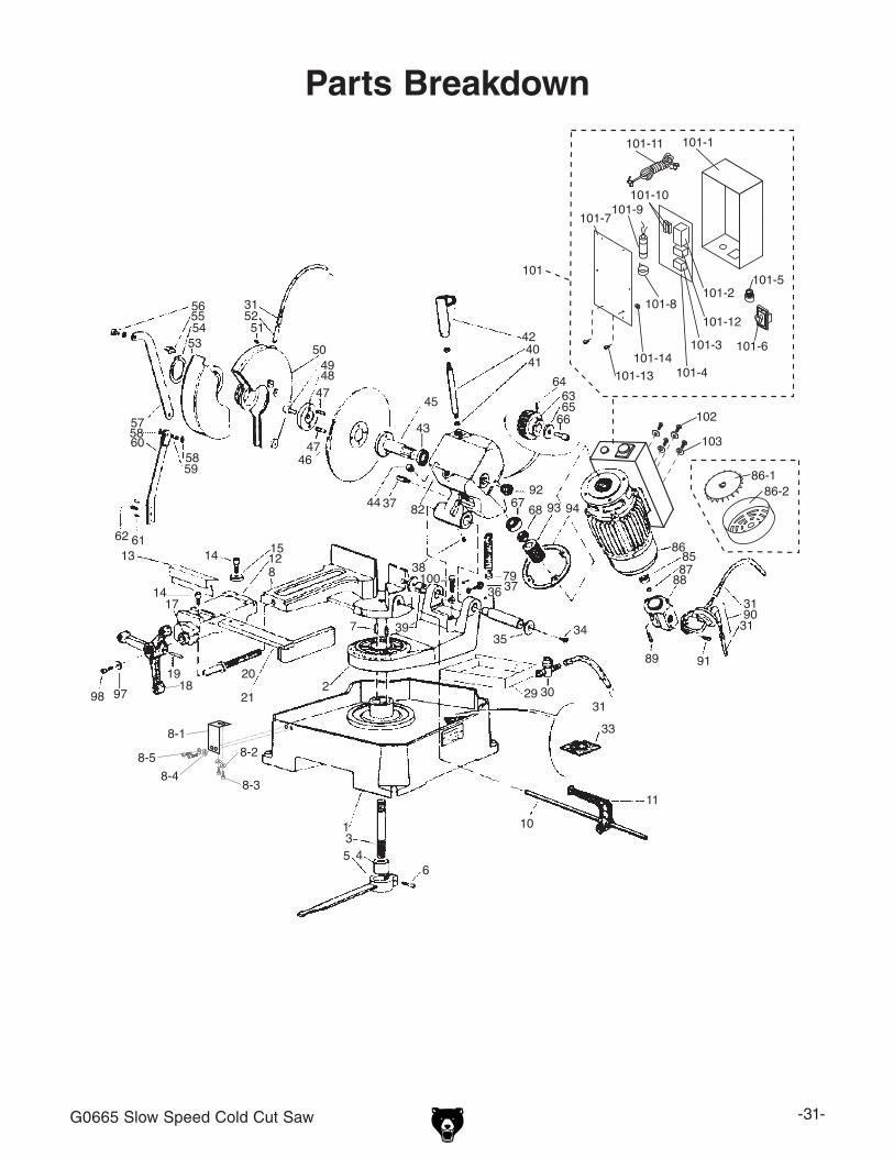
Parts breakdown

-32- g0665 slow speed Cold Cut saw
Parts ListREF PART # DESCRIPTION REF PART # DESCRIPTION
1 P0665001 MACHINE BED 55 PSB06M CAP SCREW M6-1 X 25
2 P0665002 REVOLVING ARM 56 PSB04M CAP SCREW M6-1 X 10
3 P0665003 LOCK PIN 57 P0665057 MOBILE GUARD ROD
4 P0665004 BUSHING 58 PSB14M CAP SCREW M8-1.25 X 20
5 P0665005 LEVER 59 PLN04M LOCK NUT M8-1.25
6 PSB13M CAP SCREW M8-1.25 X 30 60 P0665060 TIE ROD SUPPORT
7 P0665007 BASE PIN 61 PRP03M ROLL PIN 5 X 20
8 P0665008 VISE BASE 62 PSB11M CAP SCREW M8-1.25 X 16
8-1 P0665008-1 SUPPORT PLATE 63 P0665063 PINION GEAR
8-2 PW02M FLAT WASHER 5MM 64 PSS20M SET SCREW M8-1.25 X 8
8-3 PSB33M CAP SCREW M5-.8 X 12 65 P0665065 PINION GEAR RETAINING WASHER
8-4 PW03M FLAT WASHER 6MM 66 P0665066 SPECIAL SCREW M12-1.75 X 25
8-5 PSB04M CAP SCREW M6-1 X 10 67 P0665067 BALL BEARING 6301ZZ
10 P0665010 WORK STOP ROD 68 P0665068 SPECIAL NUT M16
11 P0665011 WORK STOP 79 P0665079 HEAD RETURN TENSION SPRING
12 P0665012 VISE 82 P0665082 GEARBOX CASE
13 P0665013 VISE JAW 85 P0665085 BALL BEARING 609
14 PSB36M CAP SCREW M12-1.75 X 25 86 P0665086 MOTOR 1-1/4HP 220V SINGLE PHASE
15 P0665015 CLAMP WASHER 86-1 P0665086-1 MOTOR FAN
17 P0665017 OILER 86-2 P0665086-2 MOTOR FAN COVER
18 P0665018 VISE HANDWHEEL 87 PR16M EXT RETAINING RING 9MM
19 PRP32M ROLL PIN 6 X 40 88 P0665088 PUMP CONNECTION BOX
20 P0665020 LEADSCREW 89 PSB16M CAP SCREW M4-.7 X 16
21 P0665021 AUXILIARY STABILIZING BRACKET 90 P0665090 COOLANT PUMP
29 P0665029 COOLANT TRAY 91 PSB02M CAP SCREW M6-1 X 20
30 P0665030 COOLANT VALVE 92 P0665092 OIL LEVEL DRAIN PLUG
31 P0665031 COOLANT TUBE 93 P0665093 WORM SCREW
33 P0665033 TANK FILTER 94 P0665094 HEAD GASKET
34 P0665034 FLAT HD SCR M8-1.25 X 20 97 PW01M FLAT WASHER 8MM
35 P0665035 SPECIAL NUT 98 PSB14M CAP SCREW M8-1.25 X 20
36 P0665036 HINGE PIN 100 PB01M HEX BOLT M10-1.5 X 30
37 P0665037 SPRING HOOK SCREW 101 P0665101 CONTROL BOX
38 PSB31M CAP SCREW M8-1.25 X 25 101-1 P0665101-1 CASE
39 P0665039 HINGE BUSHING 101-2 P0665101-2 MAGNETIC SWITCH TC-11
40 P0665040 HEAD LEVER 101-3 P0665101-3 TRANSFORMER 250V
41 PN13M HEX NUT M16-2 101-4 P0665101-4 BACKING PLATE
42 P0665042 HEAD LEVER HANDGRIP 101-5 P0665101-5 INDICATOR LIGHT
43 P0665043 RING 101-6 P0665101-6 ON/OFF SWITCH
44 P0665044 PLUG 101-7 P0665101-7 COVER
45 P0665045 BLADE SHAFT 101-8 P0665101-8 CAPACITOR STRAP
46 P0665046 BLADE 101-9 PC030E R CAPACITOR 30M 350V 1-5/8 X 3-3/8
47 P0665047 BLADE FLANGE PIN SCREW 101-10 P0665101-10 FUSE
48 P0665048 BLADE FLANGE 101-11 P0665101-11 POWER CORD
49 PSB77M CAP SCREW M12-1.75 X 30 101-12 P0665101-12 OVERLOAD RELAY TEND THR12
50 P0665050 FIXED GUARD 101-13 PS17M PHLP HD SCR M4-.7 X 6
51 PSB28M CAP SCREW M6-1 X 15 101-14 PN04M HEX NUT M4-.7
g0665 slow speed Cold Cut saw -33-
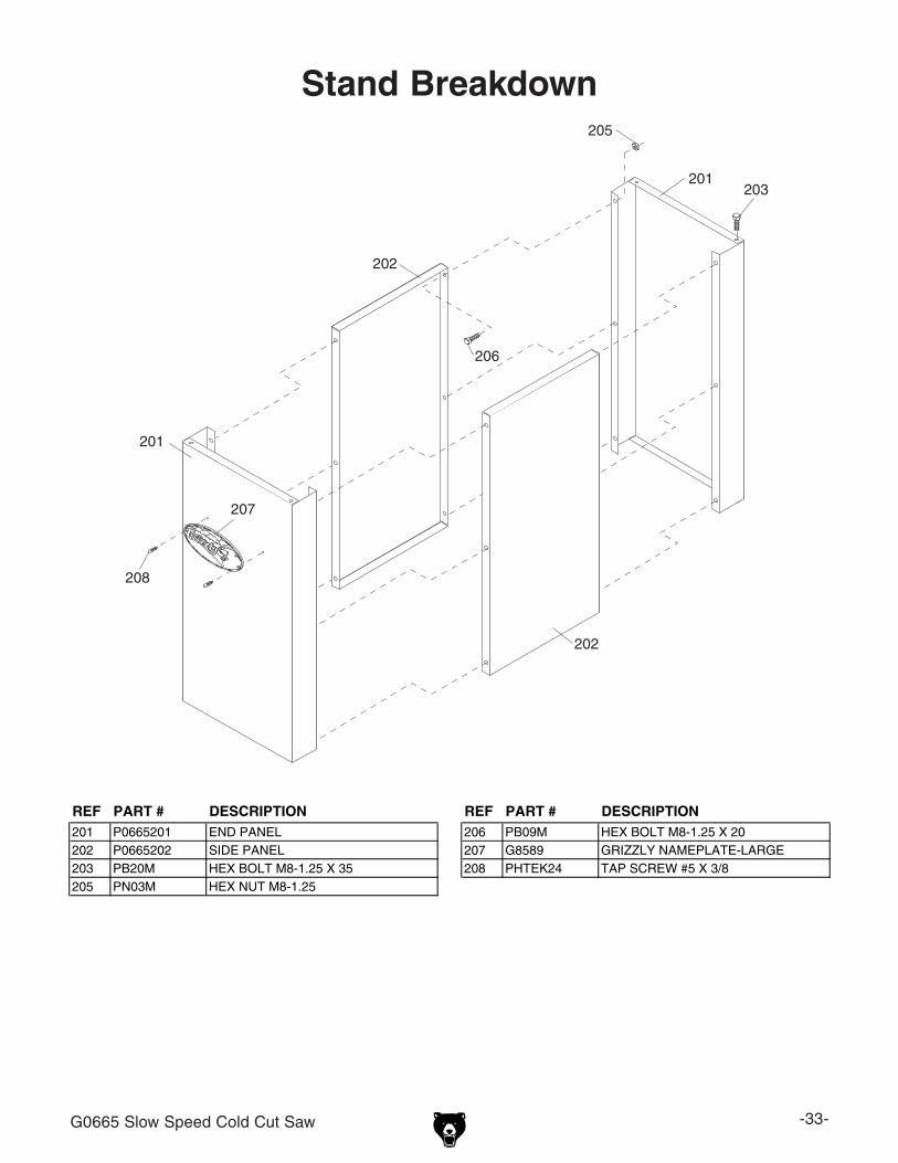
Stand breakdown
REF PART # DESCRIPTION REF PART # DESCRIPTION201 P0665201 END PANEL 206 PB09M HEX BOLT M8-1.25 X 20202 P0665202 SIDE PANEL 207 G8589 GRIZZLY NAMEPLATE-LARGE203 PB20M HEX BOLT M8-1.25 X 35 208 PHTEK24 TAP SCREW #5 X 3/8205 PN03M HEX NUT M8-1.25
-34- g0665 slow speed Cold Cut saw
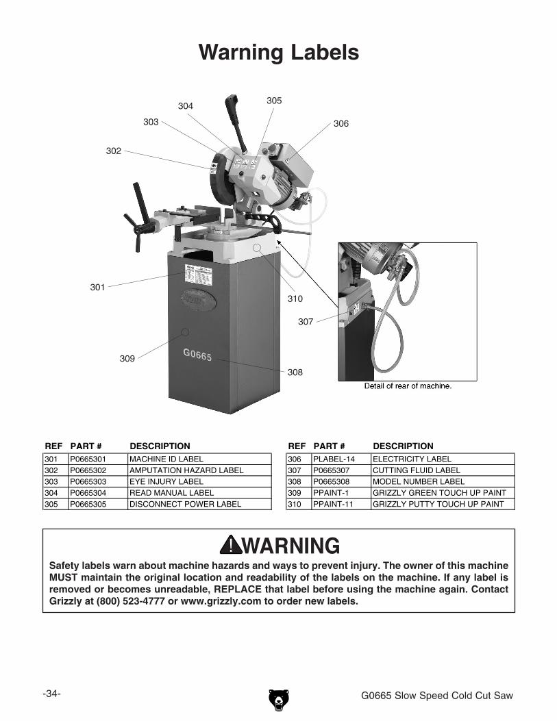
Warning Labels
Safety labels warn about machine hazards and ways to prevent injury. The owner of this machine MUST maintain the original location and readability of the labels on the machine. if any label is removed or becomes unreadable, REPLACE that label before using the machine again. Contact Grizzly at (800) 523-4777 or www.grizzly.com to order new labels.
REF PART # DESCRIPTION REF PART # DESCRIPTION301 P0665301 MACHINE ID LABEL 306 PLABEL-14 ELECTRICITY LABEL302 P0665302 AMPUTATION HAZARD LABEL 307 P0665307 CUTTING FLUID LABEL303 P0665303 EYE INJURY LABEL 308 P0665308 MODEL NUMBER LABEL304 P0665304 READ MANUAL LABEL 309 PPAINT-1 GRIZZLY GREEN TOUCH UP PAINT305 P0665305 DISCONNECT POWER LABEL 310 PPAINT-11 GRIZZLY PUTTY TOUCH UP PAINT
301
302
303
304305
306
307
308
309
310


WARRANTy AND RETURNS


![A 965 eng eBook - schuette.de · M"Vm^h adc\^ijY^cVa bdkZbZcih #####bb ) -% N"Vm^h igVchkZghZ bdkZbZci # ... CH H>CJB :G>@ -)%9 ha 9g^kZ ... &%%"[daY X]V^c bV\Vo^cZ ...](https://static.fdocuments.us/doc/165x107/5c419e4493f3c338af36a53c/a-965-eng-ebook-mvmh-adcijycva-bdkzbzcih-bb-nvmh-igvchkzghz.jpg)