MODEL G0624Z 10 BENCHTOP WOOD LATHE - Grizzlycdn1.grizzly.com/manuals/g0624z_m.pdfWOOD LATHE MANUAL...
52
COPYRIGHT © OCTOBER, 2016 BY GRIZZLY INDUSTRIAL, INC. WARNING: NO PORTION OF THIS MANUAL MAY BE REPRODUCED IN ANY SHAPE OR FORM WITHOUT THE WRITTEN APPROVAL OF GRIZZLY INDUSTRIAL, INC. (FOR MODELS MANUFACTURED SINCE 08/16) #KB18349 PRINTED IN CHINA The Model G0624Z is the same machine as the Model G0624, except the Model G0624Z has a bigger motor (0.7 HP) and includes a new tailstock handwheel, tool post base, and live and spur centers. Except for the differences noted in this insert, all other content in the Model G0624 owner's manual applies to this machine. : To reduce the risk of serious injury, you MUST read and understand this insert—and the entire Model G0624 manual—BEFORE assembling, installing, or operating this machine! If you have any further questions about this manual insert or the differences between the Model G0624 and the Model G0624Z, contact our Technical Support at (570) 546-9663 or email [email protected]. MODEL G0624Z 10" BENCHTOP WOOD LATHE MANUAL INSERT V1.12.16
Transcript of MODEL G0624Z 10 BENCHTOP WOOD LATHE - Grizzlycdn1.grizzly.com/manuals/g0624z_m.pdfWOOD LATHE MANUAL...

COPYRIGHT © OCTOBER, 2016 BY GRIZZLY INDUSTRIAL, INC.WARNING: NO PORTION OF THIS MANUAL MAY BE REPRODUCED IN ANY SHAPE
OR FORM WITHOUT THE WRITTEN APPROVAL OF GRIZZLY INDUSTRIAL, INC. (FOR MODELS MANUFACTURED SINCE 08/16) #KB18349 PRINTED IN CHINA
The Model G0624Z is the same machine as the Model G0624, except the Model G0624Z has a bigger motor (0.7 HP) and includes a new tailstock handwheel, tool post base, and live and spur centers.
Except for the differences noted in this insert, all other content in the Model G0624 owner's manual applies to this machine.
: To reduce the risk of serious injury, you MUST read and understand this insert—and the entire Model G0624 manual—BEFORE assembling, installing, or operating this machine!
If you have any further questions about this manual insert or the differences between the Model G0624 and the Model G0624Z, contact our Technical Support at (570) 546-9663 or email [email protected].
MODEL G0624Z10" BENCHTOP WOOD LATHEMANUAL INSERT
V1.12.16
-2- Model G0624Z (Mfd. Since 08/16)
The information contained herein is deemed accurate as of 12/8/2016 and represents our most recent product specifications.Due to our ongoing improvement efforts, this information may not accurately describe items previously purchased. PAGE 1 OF 2Model G0624Z
MACHINE DATASHEET
Customer Service #: (570) 546-9663 · To Order Call: (800) 523-4777 · Fax #: (800) 438-5901
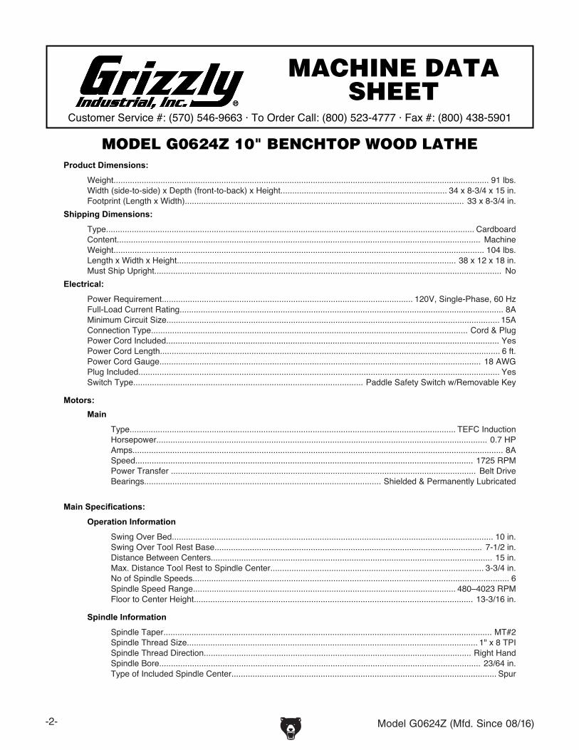
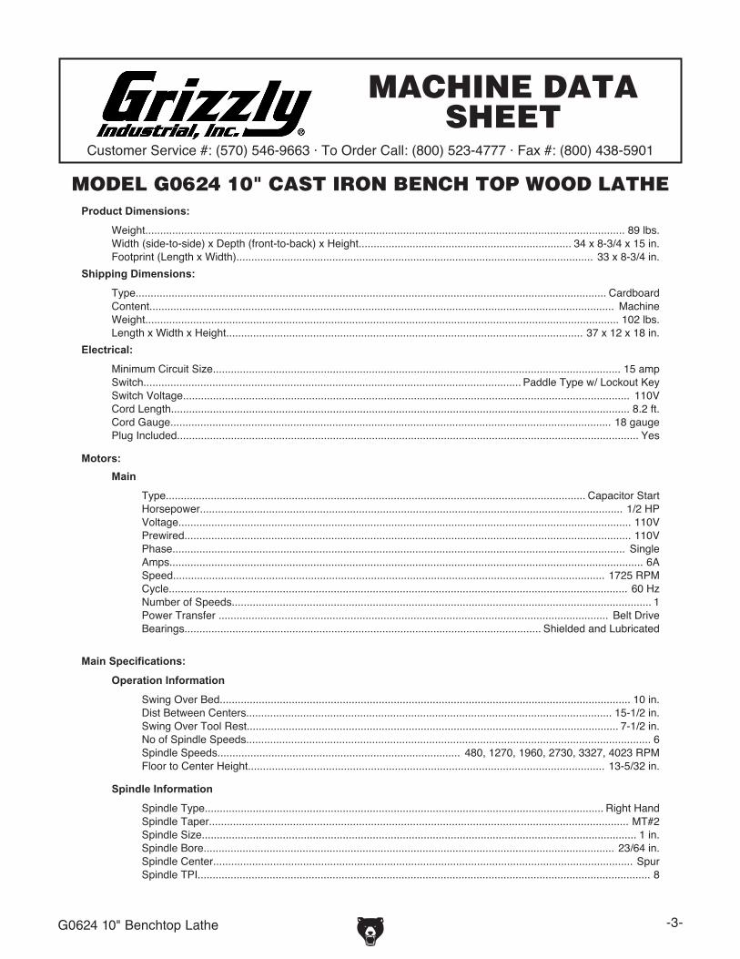
MODEL G0624Z 10" BENCHTOP WOOD LATHEProduct Dimensions:
Weight................................................................................................................................................................ 91 lbs.Width (side-to-side) x Depth (front-to-back) x Height....................................................................... 34 x 8-3/4 x 15 in.Footprint (Length x Width)....................................................................................................................... 33 x 8-3/4 in.
Shipping Dimensions:
Type............................................................................................................................................................. CardboardContent........................................................................................................................................................... MachineWeight.............................................................................................................................................................. 104 lbs.Length x Width x Height....................................................................................................................... 38 x 12 x 18 in.Must Ship Upright.................................................................................................................................................... No
Electrical:
Power Requirement........................................................................................................... 120V, Single-Phase, 60 HzFull-Load Current Rating.......................................................................................................................................... 8AMinimum Circuit Size.............................................................................................................................................. 15AConnection Type....................................................................................................................................... Cord & PlugPower Cord Included.............................................................................................................................................. YesPower Cord Length................................................................................................................................................. 6 ft.Power Cord Gauge......................................................................................................................................... 18 AWGPlug Included.......................................................................................................................................................... YesSwitch Type.................................................................................................. Paddle Safety Switch w/Removable Key
Motors:Main
Type........................................................................................................................................... TEFC InductionHorsepower............................................................................................................................................. 0.7 HPAmps.............................................................................................................................................................. 8ASpeed................................................................................................................................................ 1725 RPMPower Transfer .................................................................................................................................. Belt DriveBearings..................................................................................................... Shielded & Permanently Lubricated
Main Specifications:
Operation Information
Swing Over Bed......................................................................................................................................... 10 in.Swing Over Tool Rest Base.................................................................................................................. 7-1/2 in.Distance Between Centers........................................................................................................................ 15 in.Max. Distance Tool Rest to Spindle Center........................................................................................... 3-3/4 in.No of Spindle Speeds....................................................................................................................................... 6Spindle Speed Range................................................................................................................ 480–4023 RPMFloor to Center Height....................................................................................................................... 13-3/16 in.
Spindle Information
Spindle Taper............................................................................................................................................ MT#2Spindle Thread Size............................................................................................................................ 1" x 8 TPISpindle Thread Direction.................................................................................................................. Right HandSpindle Bore......................................................................................................................................... 23/64 in.Type of Included Spindle Center................................................................................................................. Spur

Model G0624Z (Mfd. Since 08/16) -3-
The information contained herein is deemed accurate as of 10/27/2016 and represents our most recent product specifications.Due to our ongoing improvement efforts, this information may not accurately describe items previously purchased. PAGE 2 OF 2Model G0624Z
Tool Rest Information
Tool Rest Width................................................................................................................................... 6-5/16 in.Tool Rest Post Diameter........................................................................................................................... 5/8 in.Tool Rest Post Length......................................................................................................................... 2-9/16 in.Tool Rest Base Height........................................................................................................................... 1-3/8 in.
Tailstock Information
Tailstock Taper.......................................................................................................................................... MT#2Type of Included Tailstock Center............................................................................................................... Live
Construction
Bed.......................................................................................................................... Precision-Ground Cast IronFrame...................................................................................................................................... Cast Iron & SteelStand....................................................................................................................................... Cast Iron & SteelTailstock.................................................................................................................................. Cast Iron & SteelPaint Type/Finish.................................................................................................................................... Enamel
Other Related Information
Bed Width............................................................................................................................................ 8-3/16 in.Faceplate Size............................................................................................................................................. 3 in.
Other Specifications:
Country of Origin ................................................................................................................................................ ChinaWarranty ....................................................................................................................................................... One YearSerial Number Location .................................................................................................................................. ID LabelISO 9001 Factory .................................................................................................................................................. Yes
Accessories Included:
3" FaceplateLive Rolling CenterSpur CenterTool Rest

-4- Model G0624Z (Mfd. Since 08/16)
New PartsThe Model G0624Z MT#2 spur center (see Figure 4) and MT#2 live center (see Figure 5) have integrated index spindles for improved milling precision.
The Model G0624Z features a more powerful 0.7-HP motor (see Figure 1).
Figure 1. Model G0624Z motor (bottom view).
The Model G0624Z features a new tool post base with a squared-off vertical column, and new lock handles (see Figure 2).
Figure 2. Tool post base and lock handles. The Model G0624Z now uses a strain relief to attach the power cord (see Figure 6).
The new tailstock handwheel is now solid with a longer handle (see Figure 3).
Figure 3. Tailstock handwheel and tailstock handwheel handle.
New Old
Figure 4. Comparison of G0624Z MT#2 spur center (left) and G0624 tapered index spindle
(right).
New Old
Figure 5. Comparison of MT#2 live centers: G0624Z (left) and G0624 (right).
New Old
Figure 6. Model G0624Z strain relief and power cord.
Model G0624Z (Mfd. Since 08/16) -5-
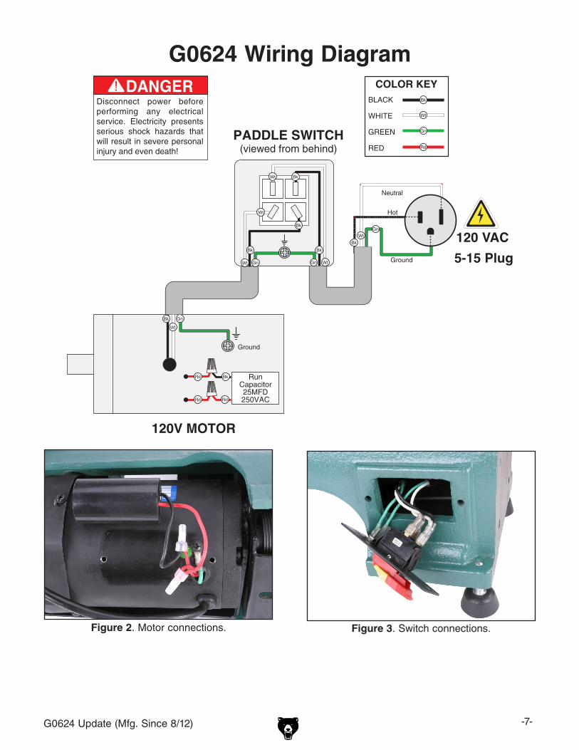
White
Neutral
Black
Hot
GreenGround
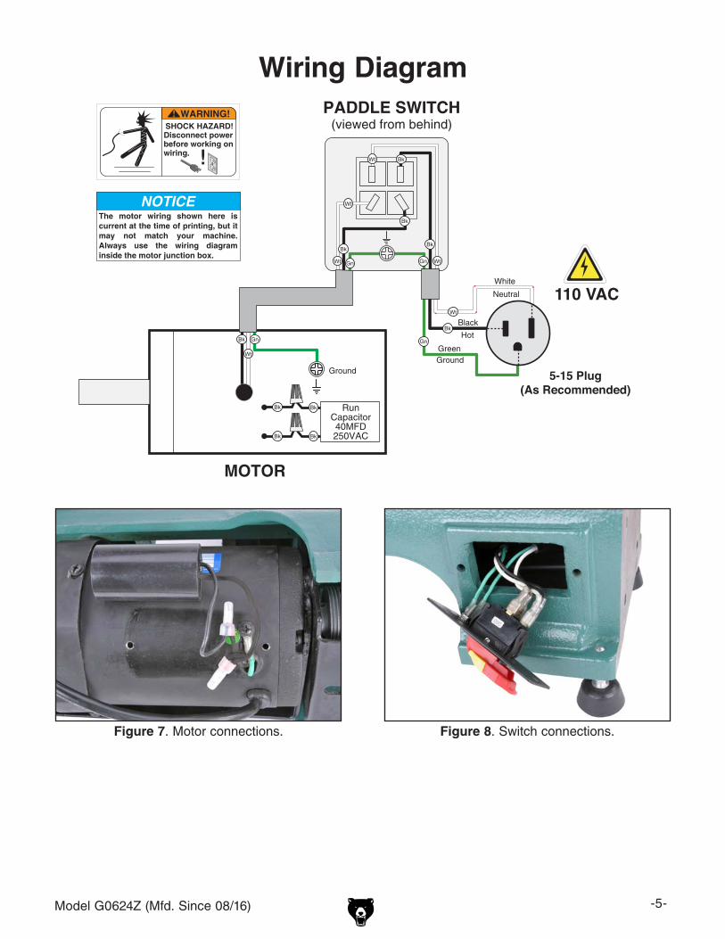
PADDLE SWITCH(viewed from behind)
MOTOR
Ground
RunCapacitor40MFD250VAC
Bk
The motor wiring shown here is current at the time of printing, but it may not match your machine. Always use the wiring diagram inside the motor junction box.
110 VAC
5-15 Plug(As Recommended)
Bk
BkBk
Figure 7. Motor connections. Figure 8. Switch connections.
Wiring Diagram

-6- Model G0624Z (Mfd. Since 08/16)
Parts Breakdown12 3
45
6 7
89
1012
14
3839
40 41424344
45464748 49
5051
5354
5556
57-1
5859 60
61626385
6566
67
68
69
70
71
7273
73
747576
77
78 7980
3635
64
83
57-257-3
57-4
57-557-6
68-368-1 68-2
68-4
84
52
68-5 68-6
57
95
1315
16 171819
2122
20
2324
25
26
303132
292827
3433
3536
37

Model G0624Z (Mfd. Since 08/16) -7-
Parts ListREF PART # DESCRIPTION REF PART # DESCRIPTION1 P0624Z001 SET SCREW M6-1 X 6 54 P0624Z054 PHLP HD SCR M5-.8 X 102 P0624Z002 HEADSTOCK HANDWHEEL 83D X 8B-S 55 P0624Z055 FLAT WASHER 5MM3 P0624Z003 PULLEY SAFETY COVER 56 P0624Z056 WIRE CLAMP4 P0624Z004 SET SCREW M4-.7 X 6 57 P0624Z057 SWITCH ASSEMBLY5 P0624Z005 SPINDLE PULLEY 57-1 P0624Z057-1 PHLP HD SCR 10-24 X 1-1/26 P0624Z006 BALL BEARING 6004ZZ 57-2 P0624Z057-2 EXT TOOTH WASHER 5MM7 P0624Z007 HEADSTOCK CASTING 57-3 P0624Z057-3 SWITCH PLATE8 P0624Z008 BALL BEARING 6005ZZ 57-4 P0624Z057-4 SWITCH BOX9 P0624Z009 SPINDLE 57-5 P0624Z057-5 HEX NUT 10-24 10 P0624Z010 SPUR CENTER MT#2 57-6 P0624Z057-6 SAFETY PADDLE SWITCH12 P0624Z012 FACEPLATE 3" 58 P0624Z058 SET SCREW M6-1 X 613 P0624Z013 LIVE CENTER MT#2 59 P0624Z059 MOTOR PULLEY14 P0624Z014 BEDWAY 60 P0624Z060 LOCK NUT M8-1.2515 P0624Z015 TAILSTOCK QUILL 61 P0624Z061 PHLP HD SCR M6-1 X 1616 P0624Z016 TAILSTOCK LEADSCREW 62 P0624Z062 MOTOR PLATE17 P0624Z017 EXT RETAINING RING 15MM 63 P0624Z063 FLAT WASHER 5MM18 P0624Z018 FLAT WASHER 15MM 64 P0624Z064 CAP SCREW M5-.8 X 15 19 P0624Z019 RUBBER COLLAR 65 P0624Z065 BELT TENSION BRACKET20 P0624Z020 TAILSTOCK CASTING 66 P0624Z066 SQUARE HEAD BOLT21 P0624Z021 ECCENTRIC SHAFT 67 P0624Z067 RUBBER SLEEVE22 P0624Z022 QUILL LOCK HANDLE M6-1 X 13 X 43 68 P0624Z068 MOTOR 0.7HP 120V 1-PH23 P0624Z023 HEX NUT M4-.7 68-1 P0624Z068-1 CAPACITOR COVER24 P0624Z024 CAP SCREW M4-.7 X 16 68-2 P0624Z068-2 R CAPACITOR 40M 250V 1.5" X 2.75"25 P0624Z025 EXT RETAINING RING 10MM 68-3 P0624Z068-3 MOTOR FAN26 P0624Z026 ROLL PIN 5 X 30 68-4 P0624Z068-4 MOTOR FAN COVER27 P0624Z027 TAILSTOCK CLAMP BOLT M10-1.5 X 65 68-5 P0624Z068-5 BALL BEARING 6202ZZ (FRONT)28 P0624Z028 TAILSTOCK LOCK PLATE 68-6 P0624Z068-6 BALL BEARING 6200ZZ (REAR)29 P0624Z029 LOCK NUT M10-1.5 69 P0624Z069 DUST GUARD30 P0624Z030 SET SCREW M6-1 X 6 70 P0624Z070 LOCK SCREW 10-24 X 631 P0624Z031 HANDWHEEL TYPE-28 80D X 16B-S X M6-1 71 P0624Z071 EXT RETAINING RING 10MM32 P0624Z032 HANDLE M6-1 X 60 72 P0624Z072 TOOL POST BASE33 P0624Z033 TAILSTOCK ECCENTRIC SHAFT 73 P0624Z073 TOOL REST LOCK HANDLE M8-1.25 X 20 X 6234 P0624Z034 EXT RETAINING RING 16MM 74 P0624Z074 TOOL REST CLAMP BOLT M10-1.5 X 5135 P0624Z035 TAILSTOCK RELEASE LEVER 110 X 13 75 P0624Z075 TOOL REST LOCK PLATE36 P0624Z036 LEVER KNOB 3/8-16 X 13/16 X 1-5/8 76 P0624Z076 LOCK NUT M10-1.537 P0624Z037 KNOCKOUT BAR 77 P0624Z077 TOOL REST38 P0624Z038 LOCK HANDLE M8-1.25 X 10 X 58 78 P0624Z078 ROLL PIN 4 X 2039 P0624Z039 GUARD PLATE 79 P0624Z079 EXT RETAINING RING 14MM40 P0624Z040 V-BELT 3V X 600L RIBBED 80 P0624Z080 TOOL POST ECCENTRIC SHAFT41 P0624Z041 COMPRESSION SPRING 0.8 X 36L X 24OD 83 P0624Z083 HEX WRENCH 2.5MM 42 P0624Z042 THREADED SHAFT M8-1.25 X 16 X 87 84 P0624Z084 STRAIN RELIEF 5/16" TYPE-143 P0624Z043 HEX NUT M8-1.25 85 P0624Z063-1 LOCK WASHER 5MM44 P0624Z044 CAP SCREW M8-1.25 X 35 87 P0624Z087 MACHINE ID LABEL45 P0624Z045 THUMB SCREW M5-.8 X 15 88 P0624Z088 FACE SHIELD LABEL46 P0624Z046 BELT TENSION LOCK KNOB 89 P0624Z089 ENTANGLEMENT HAZARD LABEL47 P0624Z047 ROLL PIN 3 X 12 90 P0624Z090 READ MANUAL LABEL48 P0624Z048 BELT TENSION LOCK SHAFT 12 X 93 91 P0624Z091 ELECTRICITY LABEL49 P0624Z049 SPACER 18MM 92 P0624Z092 TOUCH-UP PAINT, GRIZZLY GREEN50 P0624Z050 COMPRESSION SPRING 1.5 X 15L X 16OD 93 P0624Z093 GRIZZLY NAMEPLATE51 P0624Z051 MOTOR PULLEY ACCESS PLATE 94 P0624Z094 DISCONNECT POWER/SPINDLE SPD. LABEL52 P0624Z052 HEX NUT 3/8-16 95 P0624Z095 POWER CORD 18G 3W 72" 5-15P53 P0624Z053 RUBBER FOOT 3/8-16 X 1-1/2
-8- Model G0624Z (Mfd. Since 08/16)
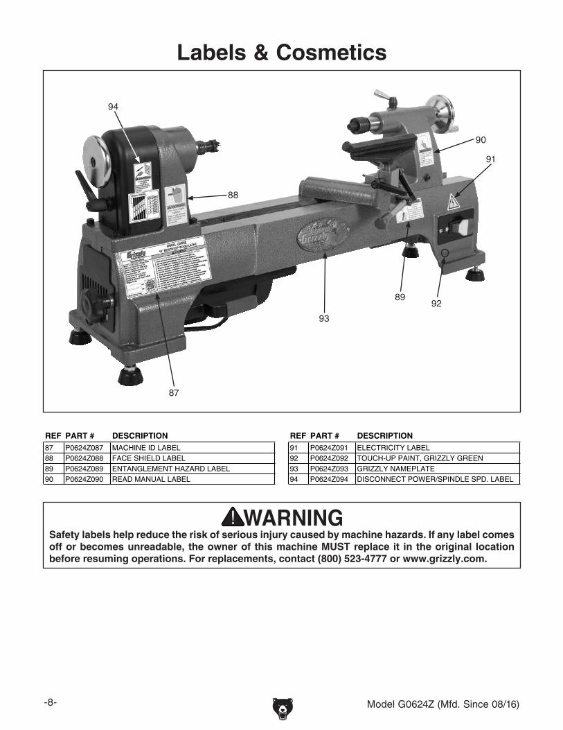
Labels & Cosmetics
Safety labels help reduce the risk of serious injury caused by machine hazards. If any label comes off or becomes unreadable, the owner of this machine MUST replace it in the original location before resuming operations. For replacements, contact (800) 523-4777 or www.grizzly.com.
94
87
88
89
90
93
91
92
REF PART # DESCRIPTION REF PART # DESCRIPTION87 P0624Z087 MACHINE ID LABEL 91 P0624Z091 ELECTRICITY LABEL88 P0624Z088 FACE SHIELD LABEL 92 P0624Z092 TOUCH-UP PAINT, GRIZZLY GREEN89 P0624Z089 ENTANGLEMENT HAZARD LABEL 93 P0624Z093 GRIZZLY NAMEPLATE90 P0624Z090 READ MANUAL LABEL 94 P0624Z094 DISCONNECT POWER/SPINDLE SPD. LABEL

The following changes were recently made to this machine since the owner's manual was printed:
• ObtainedCSAcertificationformeetingCSA22.2#71.2-08andUL987-7thstandards.• Changedthemotornominalvoltage110Vto120V.
Thisdocumentprovidesrelevantupdatestoportionsoftheowner'smanualthatnolongerapplyandaddi-tional information requiredbyCSA—aside from this information,allothercontent in theowner'smanualappliesandMUSTbereadandunderstoodforyourownsafety.IMPORTANT: Keep this update with the owner's manual for future reference.
For questions or help, contact our Tech Support at (570) 546-9663 or [email protected].
Changed SpecificationsElectrical
PowerRequirement......................................................................................120V,SinglePhase,60HzMotor
Voltage............................................................................................................................................120VSpindleSpeeds...............................................................................................................480-4000RPM
COPyRigHT©SePTeMbeR,2012bygRizzLyindUSTRiAL,inC.WARNINg: NO PORTION Of ThIS MANuAl MAy bE REPROduCEd IN ANy ShAPE
OR fORM WIThOuT ThE WRITTEN APPROvAl Of gRIzzly INduSTRIAl, INC.#bLTS15314PRinTedinCHinA
Model g0624***IMPORTANT UPDATE***
for Machines Mfg. Since August, 2012and Owner's Manual Printed November, 2006
READ THIS FIRST
New/Revised g0624 PartsREF PART # DESCRIPTION68 P0624068 MOTOR 1/2HP 120V 1-PH68-1 P0624068-1 CAPACITOR COVER68-2 P0624068-2 R CAPACITOR 25M 250V68-3 P0624068-3 MOTOR FAN68-4 P0624068-4 MOTOR FAN COVER68-5 P6202ZZ BALL BEARING 6202ZZ68-6 P6200ZZ BALL BEARING 6200ZZ87V2 P0624087V2 MACHINE ID LABEL CSA V2.08.1295 P0624095 POWER CORD 18G 3W 72" 5-15P

-2- g0624Update(Mfg.Since8/12)
ElECTRICAl EQuIPMENT INJuRy RISKS.youcanbeshocked,burned,orkilledbytouchingliveelectrical components or improperly groundedmachinery.Toreducethisrisk,onlyallowqualifiedservice personnel to do electrical installation orrepairwork,andalwaysdisconnectpowerbeforeaccessingorexposingelectricalequipment.
dISCONNECT POWER fIRST. Always discon-nectmachinefrompowersupplybeFORemakingadjustments,changingtooling,orservicingmachine.Thispreventsaninjuryriskfromunintendedstartuporcontactwithliveelectricalcomponents.
EyE PROTECTION.AlwayswearAnSi-approvedsafetyglassesorafaceshieldwhenoperatingorobserving machinery to reduce the risk of eyeinjuryorblindnessfromflyingparticles.everydayeyeglassesarenotapprovedsafetyglasses.
OWNER’S MANuAl.Readandunderstand thisowner’smanualbeFOReusingmachine.
TRAINEd OPERATORS ONly.Untrainedoper-ators have a higher risk of being hurt or killed.Onlyallow trained/supervisedpeople touse thismachine.Whenmachine isnotbeingused,dis-connect power, remove switch keys, or lock-outmachinetopreventunauthorizeduse—especiallyaroundchildren.Makeworkshopkidproof!
dANgEROuS ENvIRONMENTS. do not usemachineryinareasthatarewet,cluttered,orhavepoorlighting.Operatingmachineryintheseareasgreatlyincreasestheriskofaccidentsandinjury.
MENTAl AlERTNESS REQuIREd. Fullmentalalertnessisrequiredforsafeoperationofmachin-ery.neveroperateundertheinfluenceofdrugsoralcohol,whentired,orwhendistracted.
for your Own Safety, Read Instruction Manual before Operating this Machine
The purpose of safety symbols is to attract your attention to possible hazardous conditions. This manual uses a series of symbols and signal words intended to convey the level of impor-tance of the safety messages. The progression of symbols is described below. Remember that safety messages by themselves do not eliminate danger and are not a substitute for proper accident prevention measures. Always use common sense and good judgement.
Indicates a potentially hazardous situation which, if not avoided, MAy result in minor or moderate injury. It may also be used to alert against unsafe practices.
Indicates a potentially hazardous situation which, if not avoided, COuld result in death or serious injury.
Indicates an imminently hazardous situation which, if not avoided, WIll result in death or serious injury.
This symbol is used to alert the user to useful information about proper operation of the machine.NOTICE
Safety Instructions for Machinery
SECTION 1: SAfETy

g0624Update(Mfg.Since8/12) -3-
WEARINg PROPER APPAREl. do not wearclothing, apparel or jewelry that can becomeentangled in moving parts. Always tie back orcover longhair.Wearnon-slip footwear toavoidaccidentalslips,whichcouldcauselossofwork-piececontrol.
hAzARdOuS duST. dust created while usingmachinery may cause cancer, birth defects, orlong-term respiratorydamage.beawareofdusthazardsassociatedwitheachworkpiecematerial,andalwayswearaniOSH-approvedrespiratortoreduceyourrisk.
hEARINg PROTECTION. Always wear hear-ing protectionwhenoperating or observing loudmachinery. extended exposure to this noisewithouthearingprotectioncancausepermanenthearingloss.
REMOvE AdJuSTINg TOOlS. Tools left onmachinery can become dangerous projectilesuponstartup.neverleavechuckkeys,wrenches,or any other tools on machine. Always verifyremovalbeforestarting!
INTENdEd uSAgE. Only use machine for itsintendedpurposeandnevermakemodificationsnot approved by grizzly. Modifying machine orusing it differently than intended may result inmalfunctionormechanicalfailurethatcanleadtoseriouspersonalinjuryordeath!
AWKWARd POSITIONS. Keep proper footingandbalanceatalltimeswhenoperatingmachine.donotoverreach!Avoidawkwardhandpositionsthatmakeworkpiece control difficult or increasetheriskofaccidentalinjury.
ChIldREN & bySTANdERS. Keepchildrenandbystandersatasafedistancefromtheworkarea.Stopusingmachineiftheybecomeadistraction.
guARdS & COvERS.guardsandcoversreduceaccidental contact with moving parts or flyingdebris. Make sure they are properly installed,undamaged,andworkingcorrectly.
fORCINg MAChINERy.donotforcemachine.itwilldo the jobsaferandbetterat the rate forwhichitwasdesigned.
NEvER STANd ON MAChINE. Serious injurymay occur ifmachine is tipped or if the cuttingtoolisunintentionallycontacted.
STAblE MAChINE. Unexpectedmovementdur-ing operation greatly increases risk of injury orlossofcontrol.beforestarting,verifymachineisstableandmobilebase(ifused)islocked.
uSE RECOMMENdEd ACCESSORIES.Consultthisowner’smanualorthemanufacturerforrec-ommended accessories.Using improper acces-sorieswillincreasetheriskofseriousinjury.
uNATTENdEd OPERATION. To reduce therisk of accidental injury, turnmachineOFF andensure all moving parts completely stop beforewalking away. never leave machine runningwhileunattended.
MAINTAIN WITh CARE.Followallmaintenanceinstructions and lubrication schedules to keepmachine in good working condition. A machinethat is improperlymaintained couldmalfunction,leadingtoseriouspersonalinjuryordeath.
ChECK dAMAgEd PARTS. Regularly inspectmachine for any condition that may affect safeoperation.immediatelyrepairorreplacedamagedormis-adjustedpartsbeforeoperatingmachine.
MAINTAIN POWER CORdS. Whendisconnect-ing cord-connected machines from power, grabandpulltheplug—nOTthecord.Pullingthecordmay damage the wires inside. do not handlecord/plugwithwethands.Avoidcorddamagebykeepingitawayfromheatedsurfaces,hightrafficareas,harshchemicals,andwet/damplocations.
EXPERIENCINg dIffICulTIES. if at any timeyouexperiencedifficultiesperformingtheintend-edoperation,stopusingthemachine!ContactourTechnicalSupportat(570)546-9663.

-4- g0624Update(Mfg.Since8/12)
Additional Safety for Wood lathes
INTEgRITy Of STOCK. Verify eachworkpieceis free of knots, splits, nails, or foreignmaterialto ensure it can safely rotate on spindlewithoutbreakingapartorcausingturningtoolkickback.
WORKPIECE PREPARATION.beforemounting,cutoffwasteportionswithabandsaworothertooltoensureworkpiecehasnolargeedgestocatchturning tool, and it will rotatewithout dangerouswobbling.
SECuRINg lOCKS. Verify tool rest,headstock,andtailstockaresecurebeforeturninglatheON.
SECuRINg WORKPIECE.Animproperlysecuredworkpiece can fly off spindle with deadly force.Use proven setup techniques and always verifyworkpiece is well-secured before starting lathe.Onlyusehigh-qualityfastenerswithnon-taperedheadsforfaceplateattachment.
TOOl SuPPORT. An improperly supported toolmay be grabbed or ejected. Adjust tool restapproximately 1⁄4" away from workpiece and 1⁄8"above workpiece center line to provide propersupport for turning tool. Firmly hold turning toolwithbothhandsagainsttoolrest.
TOOl KICKbACK.Occurswhen turning tool isejected fromworkpiecewith great force, strikingoperator or bystanders. Commonly caused bypoor workpiece selection/preparation, impropertoolusage,orimpropermachinesetuportoolrestadjustment.
AdJuSTMENT TOOlS. Removeallchuckkeys,wrenches, and adjustment tools before turninglatheON.A tool lefton the lathecanbecomeadeadlyprojectilewhenspindleisstarted.
SAfE ClEARANCES. before starting spindle,verifyworkpiecehasadequateclearancebyhand-rotatingitthroughitsentirerangeofmotion.
EyE/fACE PROTECTION. Always wear a faceshieldandsafetyglasseswhenoperatinglathe.
PROPER APPAREl.donotweargloves,necktieorlooseclothing.Keepkeeplonghairawayfromrotatingspindle.
SPEEd RATES. Selectcorrectspindlespeedforworkpiece size, type, shape, and condition.Uselowspeedswhenroughingorwhenturninglarge,long,ornon-concentricworkpieces.Allowspindletoreachfullspeedbeforeturning.
NEW SETuPS.Testeachnewsetupbystartingspindlerotationatthelowestspeedandstandingtothesideofthelatheuntilworkpiecereachesfullspeedandyoucanverifysaferotation.
ROughINg. Use correct tool. Take light cuts,uselowspeeds,andfirmlysupporttoolwithbothhands.
ShARP TOOlS.Onlyusesharp turning tools—theycutwith lessresistancethandull tools.dullturning tools can catch or grab and pull yourhandsintotherotatingworkpiece.
STOPPINg SPINdlE. Always allow spindle tocompletely stop on its own.never put hands oranotherobjectonspinningworkpiece.
AdJuSTMENTS/MAINTENANCE. Make surewood lathe is turned OFF, disconnected frompower,andallmovingpartsarecompletelystoppedbeforedoingadjustmentsormaintenance.
MEASuRINg WORKPIECE. Onlymeasurework-piece after it has stopped. Trying tomeasure aspinningworkpieceincreasesentanglementrisk.
SANdINg/POlIShINg.Toreduceentanglementrisk,removetoolrestbeforesanding.nevercom-pletelywrapsandpaperaroundworkpiece.
MAIN INJuRy hAzARdS: death or crushing injury from getting entangled in rotating spindle or workpiece; death, blindness, or broken bones from being struck by a workpiece that breaks apart or comes loose during rotation, turning tool kickback, or flying wood chips. To minimize your risk of these hazards, always heed the following warning information:
MAIN INJuRy hAzARdS: gettingentangledinrotatingspindleorworkpiece,beingblindedbyflyingwoodchipsorchiselkickback,beingstruckbychiselkickbackorworkpiecesthatbreakapartorcomeloose. Tominimize your risk, always heed the followingwarning information (in addition to generalmachinesafetyinstructionsonpreviouspages).

g0624Update(Mfg.Since8/12) -5-
SECTION 2: POWER SuPPly
Availabilitybeforeinstallingthemachine,considertheavail-abilityandproximityoftherequiredpowersupplycircuit. if an existing circuit does not meet therequirementsforthismachine,anewcircuitmustbeinstalled.Tominimizetheriskofelectrocution,fire,orequipmentdamage, installationworkandelectricalwiringmustbedonebyanelectricanorqualifiedservicepersonnelinaccordancewithallapplicablecodesandstandards.
Electrocution, fire, or equipment damage may occur if machine is not correctly grounded and connected to the power supply.
full-load Current RatingThe full-load current rating is the amperage amachinedrawsat100%oftheratedoutputpower.On machines with multiple motors, this is theamperagedrawnbythelargestmotororsumofallmotorsandelectricaldevices thatmightoperateatonetimeduringnormaloperations.
full-load Current Rating at 120v ....... 6 Amps
Thefull-loadcurrentisnotthemaximumamountofampsthatthemachinewilldraw.ifthemachineisoverloaded,itwilldrawadditionalampsbeyondthefull-loadrating.
ifthemachineisoverloadedforasufficientlengthoftime,damage,overheating,orfiremayresult—especially if connected to an undersized circuit.To reduce the riskof thesehazards,avoidover-loading themachineduringoperationandmakesureitisconnectedtoapowersupplycircuitthatmeetstherequirementsinthefollowingsection.
for your own safety and protection of property, consult an electrician if you are unsure about wiring practices or electrical codes in your area.
Note: The circuit requirements listed in this man-ual apply to a dedicated circuit—where only one machine will be running at a time. If this machine will be connected to a shared circuit where mul-tiple machines will be running at the same time, consult a qualified electrician to ensure that the circuit is properly sized for safe operation.
A power supply circuit includes all electricalequipmentbetweenthebreakerboxorfusepanelinthebuildingandthemachine.Thepowersup-plycircuitusedforthismachinemustbesizedtosafelyhandlethefull-loadcurrentdrawnfromthemachine for an extended period of time. (if thismachine is connected to a circuit protected byfuses,useatimedelayfusemarkedd.)
Apowersupplycircuitincludesallelectricalequip-mentbetweenthemainbreakerboxorfusepanelinyourbuildingandtheincomingpowerconnec-tionsatthemachine.Thiscircuitmustbesizedtosafelyhandlethefull-loadcurrentdrawnfromthemachineforanextendedperiodoftime.
120v Circuit RequirementsThismachine isprewired tooperateonapowersupplycircuitthathasaverifiedgroundandmeetsthefollowingrequirements:
Nominal voltage ........................................ 120vCycle ..........................................................60 hzPhase ........................................... Single-PhasePower Supply Circuit ......................... 15 Amps
Serious injury could occur if you connect the machine to power before completing the setup process. dO NOT connect to power until instructed later in this manual.
-6- g0624Update(Mfg.Since8/12)
Extension Cords
Minimum gauge Size ...........................14 AWgMaximum length (Shorter is better).......50 ft.
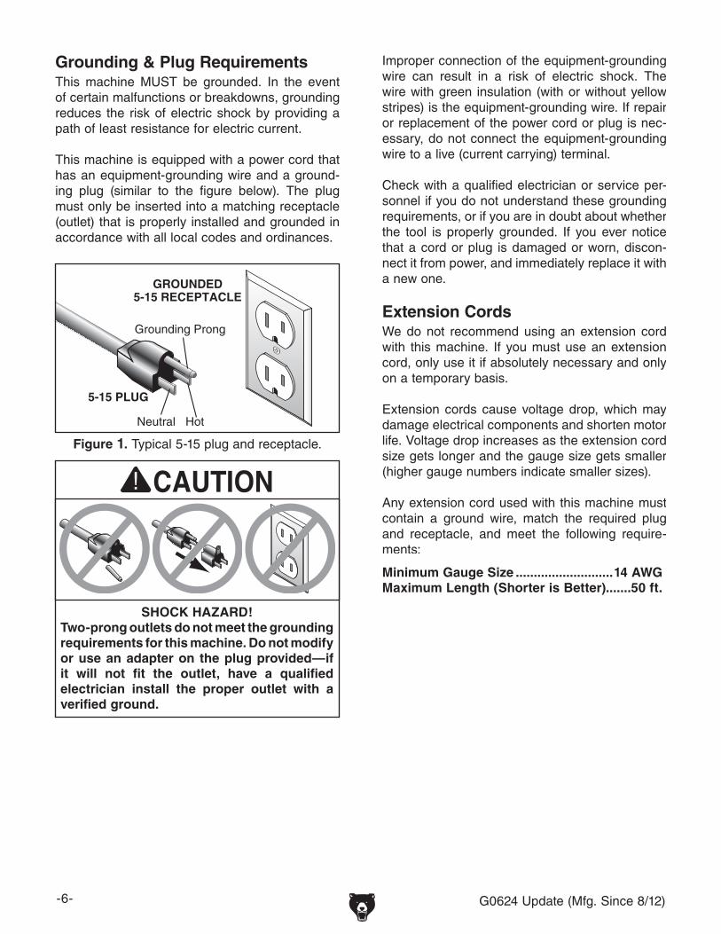
grounding & Plug Requirements
figure 1. Typical5-15plugandreceptacle.
5-15 PLUG
GROUNDED5-15 RECEPTACLE
SHOCK HAZARD!Two-prong outlets do not meet the grounding requirements for this machine. Do not modify or use an adapter on the plug provided—if it will not fit the outlet, have a qualified electrician install the proper outlet with a verified ground.
g0624Update(Mfg.Since8/12) -7-
PADDLE SWITCH
120 VAC5-15 Plug
120V MOTOR
g0624 Wiring diagram
figure 2.Motorconnections. figure 3.Switchconnections.

Buy Direct and Save with Grizzly® – Trusted, Proven and a Great Value!
~Since 1983~
ORDER24 HOURS A DAY!
1-800-523-4777
Visit Our Website Today For Current Specials!

MODEL G062410" BENCHTOP LATHE
OWNER'S MANuAL
Copyright © NoVEMBEr, 2006 By grizzly iNdustrial, iNC. rEVisEd July, 2012 (Bl)WARNiNG: NO PORTiON Of THiS MANuAL MAy BE REPRODuCED iN ANy SHAPE
OR fORM WiTHOuT THE WRiTTEN APPROvAL Of GRizzLy iNDuSTRiAL, iNC. #Bl8683 priNtEd iN ChiNa
Model G0624 shown with optional Model G0625 Bed Extension.

�������������������������������������������������������������������������������������������������������������������������������������
������������������������������������������������������������������������������������������������������������������������������������������������������������������
�������������������������������������������������������������������������������������������������������������������������������������������������������������������������������������������������������������������������������������������������������������������������������������������������������������������������������������������������������������������������������������������������������
�������������������������������������������������������������������������������������������������������������������������������������������
������������������������������������������������������������������������������������������������������������������������������������������������������������������������������������������������������������������������������������������������������
�� ������������������������������ �������������������������������������������������������������������� ����������������������������������������������������
�������������������������������������������������������������������������������������������������������������������������������������������������������������������������������������������������������������������������������������������������������������������������������������������������������

INTRODUCTION ............................................................................................................................... 2Foreword .................................................................................................................................... 2Contact Info ................................................................................................................................ 2Machine Data Sheet ................................................................................................................... 3Identification ............................................................................................................................... 5
SECTION 1: SAFETY ....................................................................................................................... 6Safety Instructions for Machinery ............................................................................................... 6Additional Safety for Wood Lathes ............................................................................................. 8
SECTION 2: CIRCUIT REQUIREMENTS ........................................................................................ 9110V Operation .......................................................................................................................... 9
SECTION 3: SET UP ...................................................................................................................... 10Set Up Safety ........................................................................................................................... 10Items Needed for Setup ........................................................................................................... 10Unpacking ................................................................................................................................ 10Inventory ................................................................................................................................... 10Clean Up .................................................................................................................................. 11Site Considerations .................................................................................................................. 11Assembly .................................................................................................................................. 12Test Run ................................................................................................................................... 12
SECTION 4: OPERATIONS ........................................................................................................... 13Operation Safety ...................................................................................................................... 13Changing Speeds ..................................................................................................................... 13Adjusting Tailstock ................................................................................................................... 14Adjusting Tool Rest .................................................................................................................. 14Installing/Removing Spur Center ............................................................................................. 15Installing/Removing Live Center .............................................................................................. 15Installing/Removing Faceplate ................................................................................................. 16Selecting Turning Tools ........................................................................................................... 16Spindle Turning ........................................................................................................................ 17Faceplate Turning .................................................................................................................... 19Sanding/Finishing ..................................................................................................................... 20
SECTION 5: ACCESSORIES ......................................................................................................... 21
SECTION 6: MAINTENANCE ........................................................................................................ 23Schedule .................................................................................................................................. 23Cleaning ................................................................................................................................... 23Unpainted Cast Iron ................................................................................................................. 23Lubrication ................................................................................................................................ 23Changing Belt ........................................................................................................................... 23
SECTION 7: SERVICE ................................................................................................................... 24Troubleshooting ........................................................................................................................ 24G0624 Wiring Diagram ............................................................................................................. 26Parts Breakdown ...................................................................................................................... 27Parts List .................................................................................................................................. 28Warning Labels Parts List ........................................................................................................ 29
WARRANTY AND RETURNS ........................................................................................................ 30
Table of Contents

-2- G0624 10" Benchtop Lathe
INTRODUCTION
Foreword
We are proud to offer the Model G0624 10" Benchtop Lathe. This machine is part of a grow-ing Grizzly family of fine woodworking machinery. When used according to the guidelines set forth in this manual, you can expect years of trouble-free, enjoyable operation and proof of Grizzly’s com-mitment to customer satisfaction.
We are pleased to provide this manual with the Model G0624. It was written to guide you through assembly, review safety considerations, and cover general operating procedures. It repre-sents our effort to produce the best documenta-tion possible.
The specifications, drawings, and photographs illustrated in this manual represent the Model G0624 as supplied when the manual was pre-pared. However, owing to Grizzly’s policy of con-tinuous improvement, changes may be made at any time with no obligation on the part of Grizzly. For your convenience, we always keep current Grizzly manuals available on our website at www.grizzly.com. Any updates to your machine will be reflected in these manuals as soon as they are complete. Visit our site often to check for the lat-est updates to this manual!
If you have any comments regarding this manual, please write to us at the address below:
Grizzly Industrial, Inc.C/O Technical Documentation Manager
P.O. Box 2069Bellingham, WA 98227-2069Email: [email protected]
We stand behind our machines. If you have any service questions or parts requests, please call or write us at the location listed below.
Grizzly Industrial, Inc.1203 Lycoming Mall Circle
Muncy, PA 17756Phone: (570) 546-9663
Fax: (800) 438-5901E-Mail: [email protected] Site: http://www.grizzly.com
Contact Info
G0624 10" Benchtop Lathe -3-
The information contained herein is deemed accurate as of 7/23/2012 and represents our most recent product specifications.Due to our ongoing improvement efforts, this information may not accurately describe items previously purchased. PAGE 1 OF 2Model G0624
Customer Service #: (570) 546-9663 · To Order Call: (800) 523-4777 · Fax #: (800) 438-5901
Product Dimensions:
Weight................................................................................................................................................................ 89 lbs.Width (side-to-side) x Depth (front-to-back) x Height....................................................................... 34 x 8-3/4 x 15 in.Footprint (Length x Width)....................................................................................................................... 33 x 8-3/4 in.
Shipping Dimensions:
Type............................................................................................................................................................. CardboardContent........................................................................................................................................................... MachineWeight.............................................................................................................................................................. 102 lbs.Length x Width x Height....................................................................................................................... 37 x 12 x 18 in.
Electrical:
Minimum Circuit Size........................................................................................................................................ 15 ampSwitch.............................................................................................................................. Paddle Type w/ Lockout KeySwitch Voltage..................................................................................................................................................... 110VCord Length......................................................................................................................................................... 8.2 ft.Cord Gauge................................................................................................................................................... 18 gaugePlug Included.......................................................................................................................................................... Yes
Motors:
Main
Type............................................................................................................................................ Capacitor StartHorsepower............................................................................................................................................. 1/2 HPVoltage....................................................................................................................................................... 110VPrewired..................................................................................................................................................... 110VPhase....................................................................................................................................................... SingleAmps.............................................................................................................................................................. 6ASpeed................................................................................................................................................ 1725 RPMCycle......................................................................................................................................................... 60 HzNumber of Speeds............................................................................................................................................ 1Power Transfer .................................................................................................................................. Belt DriveBearings....................................................................................................................... Shielded and Lubricated
Main Specifications:
Operation Information
Swing Over Bed......................................................................................................................................... 10 in.Dist Between Centers.......................................................................................................................... 15-1/2 in.Swing Over Tool Rest............................................................................................................................ 7-1/2 in.No of Spindle Speeds....................................................................................................................................... 6Spindle Speeds................................................................................. 480, 1270, 1960, 2730, 3327, 4023 RPMFloor to Center Height....................................................................................................................... 13-5/32 in.
Spindle Information
Spindle Type..................................................................................................................................... Right HandSpindle Taper............................................................................................................................................ MT#2Spindle Size................................................................................................................................................. 1 in.Spindle Bore......................................................................................................................................... 23/64 in.Spindle Center............................................................................................................................................ SpurSpindle TPI....................................................................................................................................................... 8
Machine Data Sheet

-4- G0624 10" Benchtop Lathe
The information contained herein is deemed accurate as of 7/23/2012 and represents our most recent product specifications.Due to our ongoing improvement efforts, this information may not accurately describe items previously purchased. PAGE 2 OF 2Model G0624
Tailstock Information
Tailstock Taper.......................................................................................................................................... MT#2Tailstock Center........................................................................................................................................... Live
Construction
Bed....................................................................................................................................................... Cast IronFrame.................................................................................................................................. Cast Iron and SteelHeadstock............................................................................................................................ Cast Iron and SteelTailstock............................................................................................................................... Cast Iron and SteelPaint......................................................................................................................................................... Epoxy
Other Related Information
Bed Width............................................................................................................................................ 8-3/16 in.Faceplate Size............................................................................................................................................. 3 in.
Other Specifications:
Country Of Origin ............................................................................................................................................... ChinaWarranty ........................................................................................................................................................... 1 YearSerial Number Location ....................................................................................................... Data Label on HeadstockCustomer Assembly & Setup Time ............................................................................................................ 10 minutesSound Rating ................................................................................................................................................... <80 dB
Accessories Included:
3" Face PlateLive Rolling CenterSpur CenterTool Rest
G0624 10" Benchtop Lathe -5-
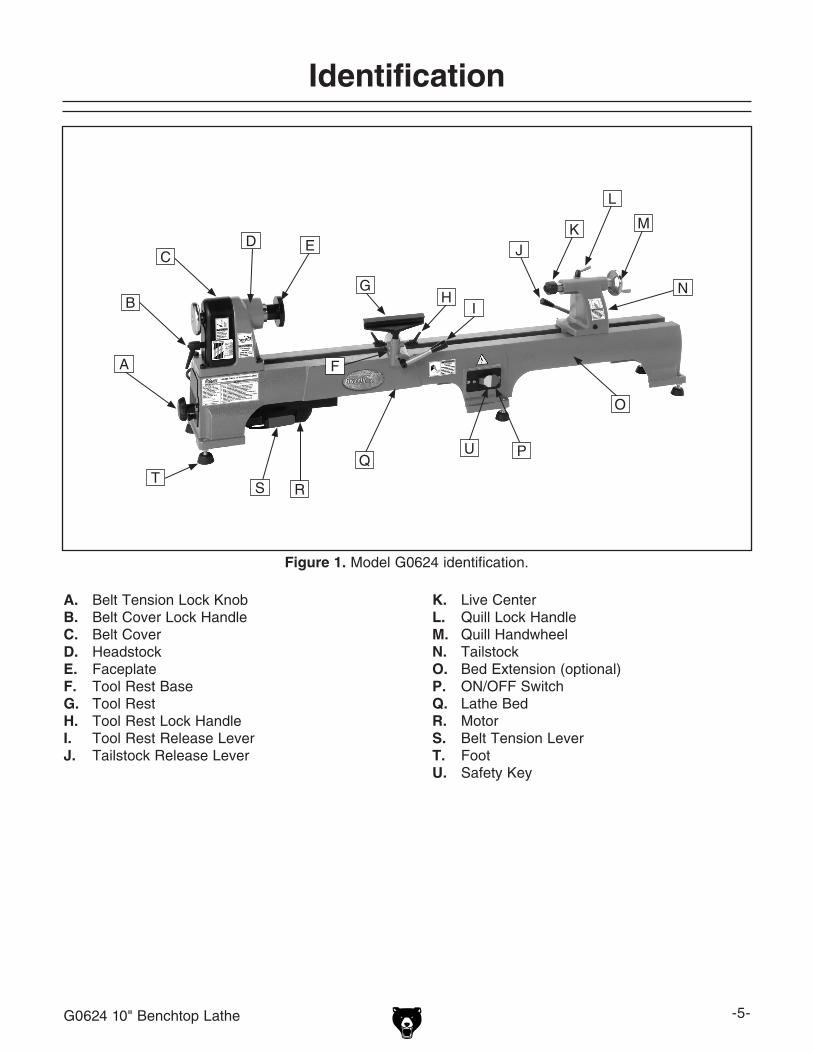
Figure 1. Model G0624 identification.
A. Belt Tension Lock KnobB. Belt Cover Lock HandleC. Belt CoverD. HeadstockE. FaceplateF. Tool Rest BaseG. Tool RestH. Tool Rest Lock HandleI. Tool Rest Release LeverJ. Tailstock Release Lever
Identification
K. Live Center L. Quill Lock HandleM. Quill HandwheelN. TailstockO. Bed Extension (optional)P. ON/OFF SwitchQ. Lathe BedR. MotorS. Belt Tension LeverT. FootU. Safety Key
A
B
CD E
F
GH
I
JK
N
O
PQ
R
L
M
ST
U

-6- G0624 10" Benchtop Lathe
Safety Instructions for Machinery
��� ������� ���� �������� ���������������� ���������� ��������������������� ������ ���� ������ ������������������������
��� ����� ������� ��������� ��� ����������������������������������������������������� �������� ��������������� ���������������������� ����������� ����� ��������� ��� ���������������������������������������������
��� ������ �������� ���������� �������������������������������������������������������������������������������������������������������������
���� ����������������������������������������������������������������������� �������� ������� �������� ��� �����������������
��� ������� ���� ����� ��������������������������������������������������� ��������� ����������� ���������� ������� ���������� ������������ �����������������������
��� ������� ����� �� ������ �������������������� ����� �������������������� ����� ��������� ����������� ����� ���� ������ ������� ����������������������
��������������������������������������������������������������������������
����������������������������������������������������������������������������������������������������������������������������������������������������������������������������������������������������������������������������������������������������������������������������������������������������������������������������������������������������������������������������������������������������������
�����������������������������������������������������������������������������������������������������������������������������������������������������������������
�����������������������������������������������������������������������������������������������������������
����������������������������������������������������������������������������������������������������������
��������������������������������������������������������������������������������������������������������
���������������������������������
�����������������

G0624 10" Benchtop Lathe -7-
��� ����� ������ �������� ���� ���������� ����������� ���������� ����������� ����������� ����� �������������������������������������������������������������
��� �������������������������������������� ���� ��������� ���� ��������� �� ����� �����������������������������
���� ���������������������������������������� ������� ���������� ���� �������������������������
���� ������ ������ ����� �������� ������������������������������������������������������ �������� �����������������������������������������������������
�������� ���� ���� ��� ������������������������������� ��������������� ��� ���������� ����������� ���������������������������������������������������
�����������������������������������������������������������������������������������������
���� ���������������������������������������������������������������������������������������������������������������� ������ ������� ���������� ����������������������������������������������
���� ������� ����������� ����� ������������� ������� �������������������������������������� ��� ������������������������������������
���� ��������� ���������� ����� ��������������������������������������������������������������������������������������������������������������������������������
���������� ����� ������� ���� ��� ���������� ����� ���������� �����������������������
��������������������������������������������� ���������� ����� ����
�������������������������������������������������������������������������� ����������������������
���� ������ ���� �������� ������������������������������������������������������������������������������������������������������������������������� ��������� ��������������� ������������������ ������������������������������������������
���� ���� ������������ �������������������������������������������������������������� ������������� ��������� �������������������������������������
�������� ���� ������ ���������������� ��������������������������������������������������������������
���� ������� ����������� ���� ������� ���������� �������� ������������������������������� �� �������� ���������� ��������� �������������������������������������������������������
���� ���������������������������������������������������������������
���� ����� ��������� ���� ������������������ ������� ���������������������������������������������������������������������������
���� ������� ����� ������� ����������� ������ ������� ��������������������
������������� ����� ���� ��� ������������� ���� ������������ �������� ��� ������� ��������������������������������������������������� ����� ��� ����� ���� ���� �������� ��� ������������������������������������������������������������������

-8- G0624 10" Benchtop Lathe
Additional Safety for Wood Lathes1. KEEPING GUARDS IN PLACE. Make sure
all guards are in place and that the lathe sits on a flat, stable surface.
2. EYE/FACE PROTECTION. Always wear eye protection or a face shield when operat-ing the lathe.
3. RESPIRATORY PROTECTION. Always wear a respirator when using this machine. Wood dust may cause allergies or long-term respiratory health problems.
4. MOUNTING WORKPIECE. Before starting, be certain the workpiece has been properly imbedded on the headstock and tailstock centers and that there is adequate clear-ance for the full rotation.
5. WORKPIECE CONDITION. Always inspect the condition of your workpiece. DO NOT turn pieces with knots, splits, and other potentially dangerous conditions. Make sure joints of glued-up pieces have high quality bonds and won't fly apart during operation.
6. ADJUSTING TOOL REST. Adjust tool rest to provide proper support for the turning tool you will be using. Test tool rest clearance by rotating workpiece by hand before turn-ing lathe ON.
7. TURNING SPEED. Select the correct tun-ing speed for your work, and allow the lathe to gain full speed before using.
8. USING SHARP CHISELS. Keep lathe chis-els properly sharpened and held firmly in position when turning.
9. OPERATING DAMAGED LATHE. Never operate the lathe with damaged or worn parts.
10. ADJUSTMENTS/MAINTENANCE. Make sure your wood lathe is turned OFF, dis-connected from its power source, and all moving parts have come to a complete stop before starting any inspection, adjustment, or maintenance procedure.
11. STOPPING LATHE. DO NOT stop the lathe by using your hand against the workpiece. Allow the lathe to stop on its own.
12. AVOIDING ENTANGLEMENT. Keep long hair and loose clothing articles such as sleeves, belts, and jewelry items away from the lathe spindle.
13. FACEPLATE TURNING. When faceplate turning, use lathe chisels on the downward spinning side of the workpiece only.
14. SANDING/POLISHING. Remove the tool rest when performing sanding or polishing operations on the rotating spindle.
15. MATERIAL REMOVAL RATE. Removing too much material at once may cause workpiece to fly out of the lathe.
16. REDUCING WORKPIECE VIBRATION. If the workpiece vibrates, immediately turn the lathe OFF. Check to make sure the workpiece is centered and balanced. Trim excess waste off corners with a bandsaw or table saw to reduce vibration. Make sure workpiece is securely attached in setup.
No list of safety guidelines can be complete. Every shop environment is different. Always consider safety first, as it applies to your individual working conditions. Use this and other machinery with caution and respect. Failure to do so could result in serious per-sonal injury, damage to equipment, or poor work results.
Like all machinery there is potential danger when operating this machine. Accidents are frequently caused by lack of familiarity or failure to pay attention. Use this machine with respect and caution to lessen the pos-sibility of operator injury. If normal safety precautions are overlooked or ignored, seri-ous personal injury may occur.
G0624 10" Benchtop Lathe -9-
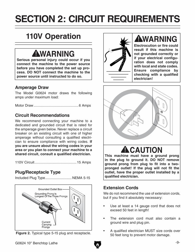
Figure 2. Typical type 5-15 plug and receptacle.
Serious personal injury could occur if you connect the machine to the power source before you have completed the set up pro-cess. DO NOT connect the machine to the power source until instructed to do so.
110V Operation
Amperage DrawThe Model G0624 motor draws the following amps under maximum load:
Motor Draw ..............................................6 Amps
Circuit RecommendationsWe recommend connecting your machine to a dedicated and grounded circuit that is rated for the amperage given below. Never replace a circuit breaker on an existing circuit with one of higher amperage without consulting a qualified electri-cian to ensure compliance with wiring codes. If you are unsure about the wiring codes in your area or you plan to connect your machine to a shared circuit, consult a qualified electrician.
110V Circuit ...........................................15 Amps
Plug/Receptacle TypeIncluded Plug Type ........................... NEMA 5-15
This machine must have a ground prong in the plug to ground it. DO NOT remove ground prong from plug to fit into a two-pronged outlet! If the plug will not fit the outlet, have the proper outlet installed by a qualified electrician.
Extension CordsWe do not recommend the use of extension cords, but if you find it absolutely necessary:
• Use at least a 14 gauge cord that does not exceed 50 feet in length!
• The extension cord must also contain a ground wire and plug pin.
• A qualified electrician MUST size cords over 50 feet long to prevent motor damage.
Electrocution or fire could result if this machine is not grounded correctly or if your electrical configu-ration does not comply with local and state codes. Ensure compliance by checking with a qualified electrician!
SECTION 2: CIRCUIT REQUIREMENTS
-10- G0624 10" Benchtop Lathe
Wear safety glasses dur-ing the entire set up pro-cess!
This machine presents serious injury hazards to untrained users. Read through this entire manu-al to become familiar with the controls and opera-tions before starting the machine!
Set Up Safety
SECTION 3: SET UP
The Model G0624 is a heavy machine. DO NOT over-exert yourself while unpacking or moving your machine—get assis-tance.
The following items are needed to complete the setup process, but are not included with your machine:
Description Qty• Cleaning Solvent (as needed) .................... 1
Items Needed for Setup
The Model G0624 was carefully packed when it left our warehouse. If you discover the machine is damaged after you have signed for delivery, please immediately call Customer Service at (570) 546-9663 for advice.
Save the containers and all packing materials for possible inspection by the carrier or its agent. Otherwise, filing a freight claim can be difficult.
When you are completely satisfied with the condi-tion of your shipment, inventory the contents.
Unpacking
Inventory
After all the parts have been removed from the box, you should have the following items:
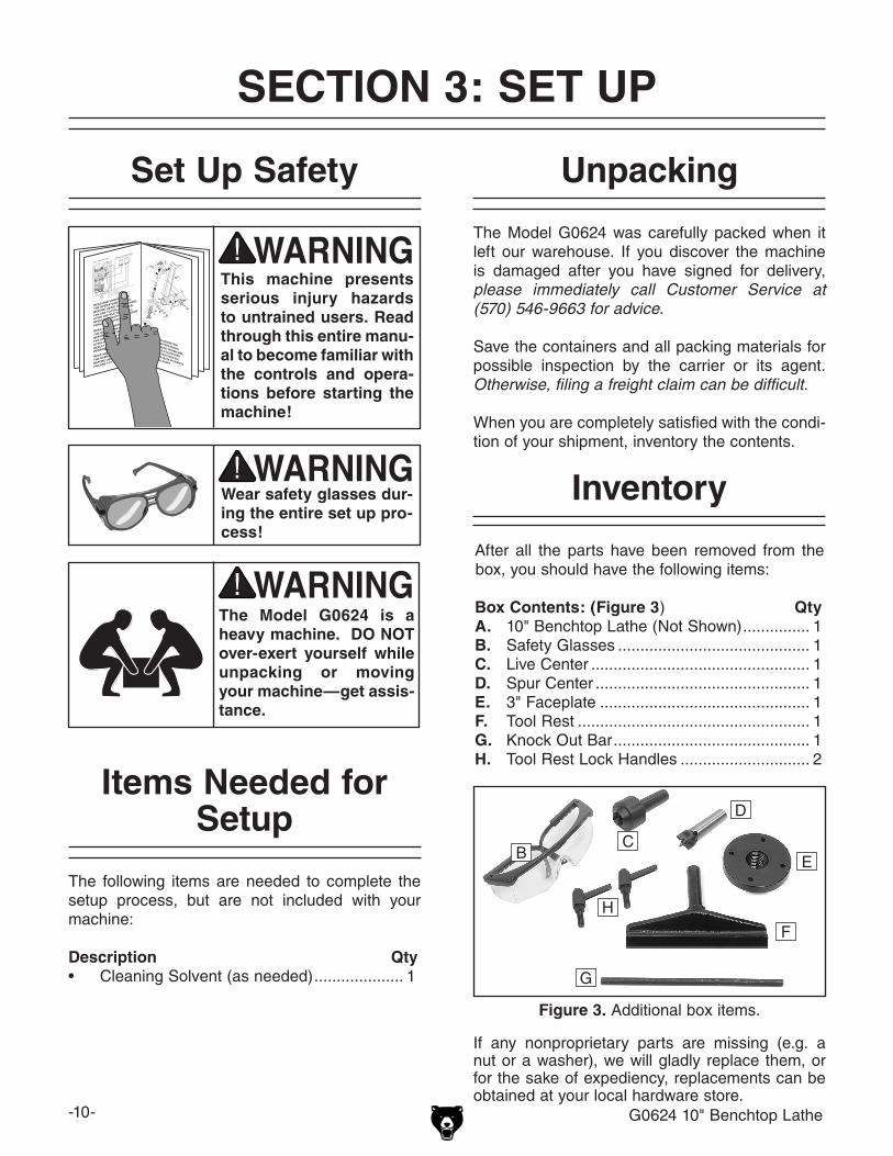
Box Contents: (Figure 3) QtyA. 10" Benchtop Lathe (Not Shown) ............... 1B. Safety Glasses ........................................... 1C. Live Center ................................................. 1D. Spur Center ................................................ 1E. 3" Faceplate ............................................... 1F. Tool Rest .................................................... 1G. Knock Out Bar ............................................ 1H. Tool Rest Lock Handles ............................. 2
If any nonproprietary parts are missing (e.g. a nut or a washer), we will gladly replace them, or for the sake of expediency, replacements can be obtained at your local hardware store.
Figure 3. Additional box items.
BC
D
E
F
G
H
G0624 10" Benchtop Lathe -11-
Floor LoadRefer to the Machine Data Sheet for the weight and footprint specifications of your machine. Some workbenches may require additional rein-forcement to support both the machine and the workpiece.
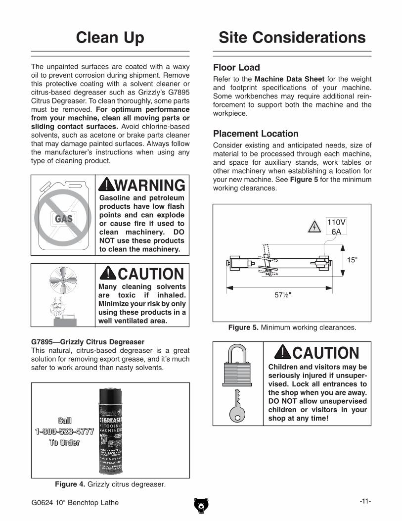
Placement LocationConsider existing and anticipated needs, size of material to be processed through each machine, and space for auxiliary stands, work tables or other machinery when establishing a location for your new machine. See Figure 5 for the minimum working clearances.
Children and visitors may be seriously injured if unsuper-vised. Lock all entrances to the shop when you are away. DO NOT allow unsupervised children or visitors in your shop at any time!
The unpainted surfaces are coated with a waxy oil to prevent corrosion during shipment. Remove this protective coating with a solvent cleaner or citrus-based degreaser such as Grizzly’s G7895 Citrus Degreaser. To clean thoroughly, some parts must be removed. For optimum performance from your machine, clean all moving parts or sliding contact surfaces. Avoid chlorine-based solvents, such as acetone or brake parts cleaner that may damage painted surfaces. Always follow the manufacturer’s instructions when using any type of cleaning product.
Site ConsiderationsClean Up
Figure 5. Minimum working clearances.
57½"
15"
110V6A
Gasoline and petroleum products have low flash points and can explode or cause fire if used to clean machinery. DO NOT use these products to clean the machinery.
Many cleaning solvents are toxic if inhaled. Minimize your risk by only using these products in a well ventilated area.
Figure 4. Grizzly citrus degreaser.
G7895—Grizzly Citrus DegreaserThis natural, citrus-based degreaser is a great solution for removing export grease, and it’s much safer to work around than nasty solvents.
-12- G0624 10" Benchtop Lathe
Assembly
To install the tool rest:
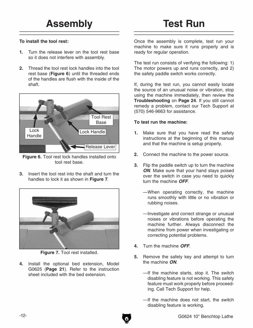
1. Turn the release lever on the tool rest base so it does not interfere with assembly.
2. Thread the tool rest lock handles into the tool rest base (Figure 6) until the threaded ends of the handles are flush with the inside of the shaft.
Figure 6. Tool rest lock handles installed onto tool rest base.
3. Insert the tool rest into the shaft and turn the handles to lock it as shown in Figure 7.
Figure 7. Tool rest installed.
Test Run
Once the assembly is complete, test run your machine to make sure it runs properly and is ready for regular operation.
The test run consists of verifying the following: 1) The motor powers up and runs correctly, and 2) the safety paddle switch works correctly.
If, during the test run, you cannot easily locate the source of an unusual noise or vibration, stop using the machine immediately, then review the Troubleshooting on Page 24. If you still cannot remedy a problem, contact our Tech Support at (570) 546-9663 for assistance.
To test run the machine:
1. Make sure that you have read the safety instructions at the beginning of this manual and that the machine is setup properly.
2. Connect the machine to the power source.
3. Flip the paddle switch up to turn the machine ON. Make sure that your hand stays poised over the switch in case you need to quickly turn the machine OFF.
—When operating correctly, the machine runs smoothly with little or no vibration or rubbing noises.
— Investigate and correct strange or unusual noises or vibrations before operating the machine further. Always disconnect the machine from power when investigating or correcting potential problems.
4. Turn the machine OFF.
5. Remove the safety key and attempt to turn the machine ON.
—If the machine starts, stop it. The switch disabling feature is not working. This safety feature must work properly before proceed-ing. Call Tech Support for help.
—If the machine does not start, the switch disabling feature is working.
Release Lever
Tool Rest Base
4. Install the optional bed extension, Model G0625 (Page 21). Refer to the instruction sheet included with the bed extension.
Lock HandleLock Handle

G0624 10" Benchtop Lathe -13-
Damage to your eyes and lungs could result from using this machine without proper pro-tective gear. Always wear safety glasses and a respirator when operating this machine.
Loose hair and cloth-ing could get caught in machinery and cause seri-ous personal injury. Keep loose clothing and long hair away from moving machinery.
Operation Safety
SECTION 4: OPERATIONS
NOTICEIf you have never used this type of machine or equipment before, WE STRONGLY REC-OMMEND that you read books, trade maga-zines, or get formal training before begin-ning any projects. Regardless of the con-tent in this section, Grizzly Industrial will not be held liable for accidents caused by lack of training.
To change speeds, the belt in the headstock must be rearranged. A chart on the pulley cover shows the belt positions needed to make the lathe run at the desired speed.
Changing Speeds
���� �����
� ���
�����
����
����
����
����
�
�
�
�
�
��
���
������������
�
Figure 9. G0624 Spindle speeds.
2. Loosen the belt tension lock knob, and move the belt tension lever up to reduce tension on the belt.
3. Locate the desired speed on the speed chart on the belt cover, and move the belt to the desired grooves on the motor and spindle pulleys.
For Example: As indicated in the speed chart, belt position B creates 1270 RPM (Figure 9).
To change speeds:
1. Loosen the lock handle, remove the belt cover, and open the access plate (Figure 8).
Figure 8. Belt access.
Belt Tension Lock Knob
Access Plate
Belt Tension Lever
Lock Handle
Belt Cover
4. Move the belt tension lever down, tighten the lock knob, and reinstall the access plate and belt cover.

-14- G0624 10" Benchtop Lathe
The tailstock is equipped with a cam-action clamping system to secure it to the lathe bed. When the lever is tightened, a locking plate lifts up and secures the tool rest to the bed.
To position the tailstock along the bed:
1. Loosen the release lever and move the tailstock to the desired position (Figure 10).
Adjusting Tailstock
Figure 10. Tailstock controls.
Release Lever
2. Re-engage the release lever.
3. If the release lever will not lock the tailstock down onto the bed (either too loose or too tight), loosen or tighten the hex nut (located on the underside of the tailstock) in small increments as needed to achieve the proper clamping pressure.
The tool rest is equipped with a cam-action clamping system to secure it to the lathe bed. When the lever is engaged, a locking plate lifts up and secures the tool rest base to the bed.
To position the tool rest base along the bed:
1. Loosen the release lever and slide the tool rest base along the bed (Figure 11).
Figure 11. Tool rest controls.
Adjusting Tool Rest
2. Re-engage the release lever to lock the tool rest base in place.
— If the release lever will not lock the tool rest base onto the bed (either too loose or too tight), then loosen or tighten the hex nut (located on the underside of the tool rest base) in small increments as needed to achieve the proper clamping pressure.
To adjust the tool rest vertically:
1. Loosen the lock handles (Figure 11) and adjust the tool rest vertically or swivel it as needed.
2. Tighten the lock handles.
Release Lever
Tool Rest Base
Lock HandleLock
Handle
G0624 10" Benchtop Lathe -15-
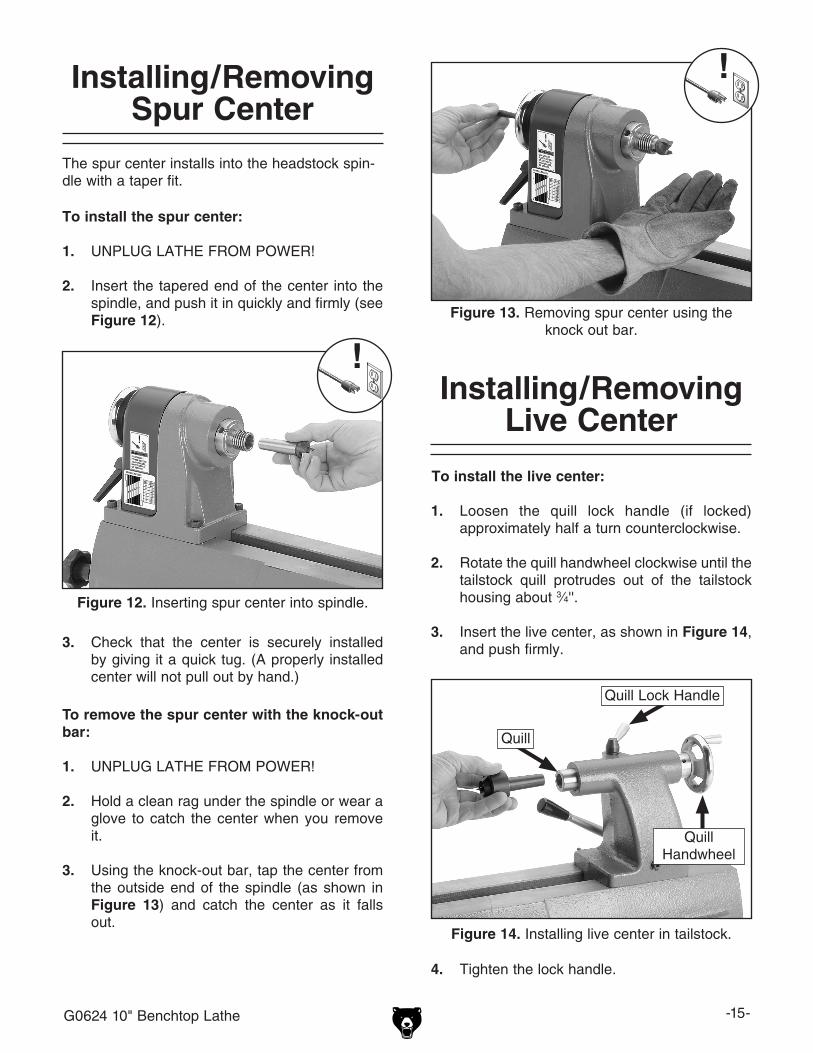
Installing/Removing Spur Center
The spur center installs into the headstock spin-dle with a taper fit.
To install the spur center:
1. UNPLUG LATHE FROM POWER!
2. Insert the tapered end of the center into the spindle, and push it in quickly and firmly (see Figure 12).
Figure 12. Inserting spur center into spindle.
3. Check that the center is securely installed by giving it a quick tug. (A properly installed center will not pull out by hand.)
To remove the spur center with the knock-out bar:
1. UNPLUG LATHE FROM POWER!
2. Hold a clean rag under the spindle or wear a glove to catch the center when you remove it.
3. Using the knock-out bar, tap the center from the outside end of the spindle (as shown in Figure 13) and catch the center as it falls out.
Figure 13. Removing spur center using the knock out bar.
Installing/Removing Live Center
To install the live center:
1. Loosen the quill lock handle (if locked) approximately half a turn counterclockwise.
2. Rotate the quill handwheel clockwise until the tailstock quill protrudes out of the tailstock housing about 3⁄4''.
3. Insert the live center, as shown in Figure 14, and push firmly.
Figure 14. Installing live center in tailstock.
Quill Lock Handle
Quill Handwheel
Quill
4. Tighten the lock handle.

-16- G0624 10" Benchtop Lathe
To remove the live center:
1. Turn the quill handwheel counterclockwise until the tailstock quill bottoms out, causing the center to be forced out of the quill.
The tailstock quill lock handle must always be locked down while the lathe is in use. The workpiece can be thrown from the lathe if this step is not observed. Also, the tailstock quill should not protrude from the tailstock housing more than 2'' or the quill will not be supported enough. Failure to follow these warnings may result in personal injury.
Installing/Removing Faceplate
The faceplate can be installed only if the spur cen-ter has been removed from the headstock spindle. The knock-out bar is included with the lathe for installing and removing the faceplate.
To install the faceplate:
1. UNPLUG LATHE FROM POWER!
2. Remove the spur center (See Page 15).
3. Thread the faceplate onto the headstock spindle.
4. Using the knock-out bar, hand tighten the faceplate as shown in Figure 15.
Note: Reverse Steps 3-4 to remove the face-plate.
Figure 15. Tightening faceplate.
To mount a workpiece to your faceplate, refer to Page 19.
Selecting Turning Tools
Lathe tools come in a variety of shapes and sizes and usually fall into five major categories.
• Gouges—Mainly used for rough cutting, detail cutting, and cove profiles. The rough gouge is a hollow, double-ground tool with a round nose, and the detail gouge is a hol-low, double-ground tool with either a round or pointed nose. Figure 16 shows an example of a gouge.
Figure 16. Gouge.
• Skew Chisel—A very versatile tool that can be used for planing, squaring, V-cutting, beading, and parting off. The skew chisel is flat, double-ground with one side higher than the other (usually at an angle of 20-40˚).
G0624 10" Benchtop Lathe -17-
Figure 17 shows an example of a skew chisel.
Figure 17. Skew chisel.
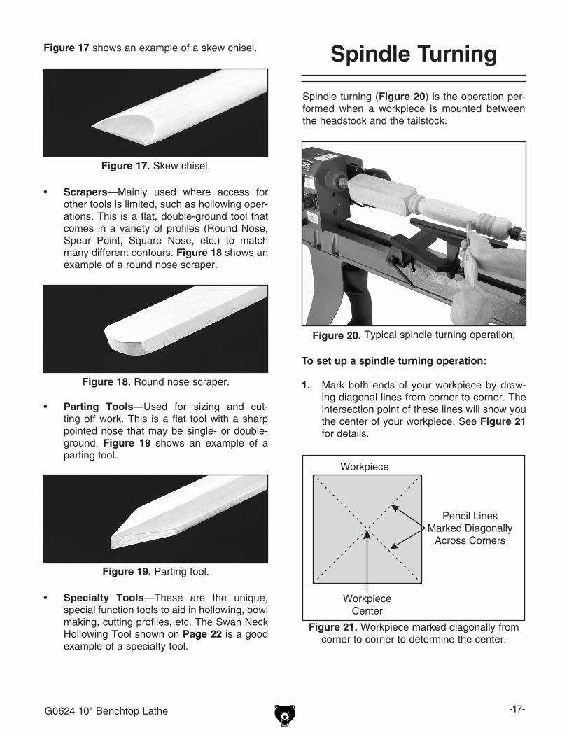
• Scrapers—Mainly used where access for other tools is limited, such as hollowing oper-ations. This is a flat, double-ground tool that comes in a variety of profiles (Round Nose, Spear Point, Square Nose, etc.) to match many different contours. Figure 18 shows an example of a round nose scraper.
Figure 18. Round nose scraper.
Figure 19. Parting tool.
• Parting Tools—Used for sizing and cut-ting off work. This is a flat tool with a sharp pointed nose that may be single- or double-ground. Figure 19 shows an example of a parting tool.
• Specialty Tools—These are the unique, special function tools to aid in hollowing, bowl making, cutting profiles, etc. The Swan Neck Hollowing Tool shown on Page 22 is a good example of a specialty tool.
Spindle turning (Figure 20) is the operation per-formed when a workpiece is mounted between the headstock and the tailstock.
Spindle Turning
���������
���������������
�������������������������������������������
Figure 21. Workpiece marked diagonally from corner to corner to determine the center.
Figure 20. Typical spindle turning operation.
To set up a spindle turning operation:
1. Mark both ends of your workpiece by draw-ing diagonal lines from corner to corner. The intersection point of these lines will show you the center of your workpiece. See Figure 21 for details.
-18- G0624 10" Benchtop Lathe
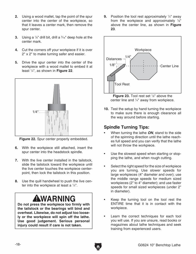
����
Figure 22. Spur center properly embedded.
2. Using a wood mallet, tap the point of the spur center into the center of the workpiece, so that it leaves a center mark, then remove the spur center.
3. Using a 1⁄8" drill bit, drill a 3⁄16" deep hole at the center mark.
4. Cut the corners off your workpiece if it is over 2" x 2" to make turning safer and easier.
5. Drive the spur center into the center of the workpiece with a wood mallet to embed it at least 1⁄4", as shown in Figure 22.
6. With the workpiece still attached, insert the spur center into the headstock spindle.
7. With the live center installed in the tailstock, slide the tailstock toward the workpiece until the live center touches the workpiece center-point, then lock the tailstock in this position.
8. Use the quill handwheel to push the live cen-ter into the workpiece at least a 1⁄4".
Do not press the workpiece too firmly with the tailstock or the bearings will bind and overheat. Likewise, do not adjust too loose-ly or the workpiece will spin off the lathe. Use good judgement. Serious personal injury could result if care is not taken.
9. Position the tool rest approximately 1⁄4" away from the workpiece and approximately 1⁄8" above the center line, as shown in Figure 23.
10. Test the setup by hand turning the workpiece to make sure there is enough clearance all the way around before starting.
Spindle Turning Tips:• When turning the lathe ON, stand to the side
of the spinning direction until the lathe reach-es full speed and you can verify that the lathe will not throw the workpiece.
• Use the slowest speed when starting or stop-ping the lathe, and when rough cutting.
• Select the right speed for the size of workpiece you are turning. Use slower speeds for large workpieces (4" diameter and over); use the middle range speeds for medium sized workpieces (2" to 4" diameter); and use faster speeds for small sized workpieces (under 2" in diameter).
• Keep the turning tool on the tool rest the ENTIRE time that it is in contact with the workpiece.
• Learn the correct techniques for each tool you will use. If you are unsure, read books or magazines about lathe techniques and seek training from experienced users.
���������
�����������
���������
���������
����
����
Figure 23. Tool rest set 1⁄8" above the center line and 1⁄4" away from workpiece.
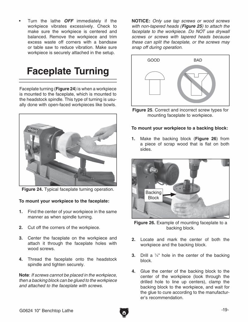
G0624 10" Benchtop Lathe -19-
Figure 24. Typical faceplate turning operation.
Faceplate turning (Figure 24) is when a workpiece is mounted to the faceplate, which is mounted to the headstock spindle. This type of turning is usu-ally done with open-faced workpieces like bowls.
Faceplate Turning
To mount your workpiece to the faceplate:
1. Find the center of your workpiece in the same manner as when spindle turning.
2. Cut off the corners of the workpiece.
3. Center the faceplate on the workpiece and attach it through the faceplate holes with wood screws.
4. Thread the faceplate onto the headstock spindle and tighten securely.
Note: If screws cannot be placed in the workpiece, then a backing block can be glued to the workpiece and attached to the faceplate with screws.
Figure 26. Example of mounting faceplate to a backing block.
NOTICE: Only use tap screws or wood screws with non-tapered heads (Figure 25) to attach the faceplate to the workpiece. Do NOT use drywall screws or screws with tapered heads because these can split the faceplate, or the screws may snap off during operation.
Backing Block
2. Locate and mark the center of both the workpiece and the backing block.
3. Drill a 1⁄4" hole in the center of the backing block.
4. Glue the center of the backing block to the center of the workpiece (look through the drilled hole to line up centers), clamp the backing block to the workpiece, and wait for the glue to cure according to the manufactur-er’s recommendation.
• Turn the lathe OFF immediately if the workpiece vibrates excessively. Check to make sure the workpiece is centered and balanced. Remove the workpiece and trim excess waste off corners with a bandsaw or table saw to reduce vibration. Make sure workpiece is securely attached in the setup.
To mount your workpiece to a backing block:
1. Make the backing block (Figure 26) from a piece of scrap wood that is flat on both sides.
����� ���
Figure 25. Correct and incorrect screw types for mounting faceplate to workpiece.

-20- G0624 10" Benchtop Lathe
After turning, the workpiece can be sanded, as shown in Figure 27, and finished (in the same manner) before removing it from the lathe.
Figure 27. Typical sanding operation.
Sanding/Finishing
Whenever sanding or finishing, move the tool rest holder out of the way to increase personal safety and gain adequate working room.
���������
���������
Wrapping the sandpa-per completely around the workpiece will pull your hands into the mov-ing workpiece and may cause injury. Never wrap sandpaper completely around the workpiece!
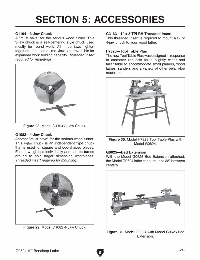
G0624 10" Benchtop Lathe -21-
SECTION 5: ACCESSORIESACCESSORIES
G1194—3-Jaw ChuckA "must have" for the serious wood turner. This 3-jaw chuck is a self-centering style chuck used mostly for round work. All three jaws tighten together at the same time. Jaws are reversible for expanded work holding capacity. Threaded insert required for mounting!
Figure 28. Model G1194 3-Jaw Chuck.
G1082—4-Jaw ChuckAnother "must have" for the serious wood turner.This 4-jaw chuck is an independent type chuck that is used for square and odd-shaped pieces. Each jaw tightens individually and can be turned around to hold larger dimension workpieces. Threaded insert required for mounting!
Figure 29. Model G1082 4-Jaw Chuck.
H7828—Tool Table PlusThe new Tool Table Plus was designed in response to customer requests for a slightly wider and taller table to accommodate small planers, wood lathes, sanders and a variety of other bench-top machines.
Figure 30. Model H7828 Tool Table Plus with Model G0624.
G3163—1" x 8 TPI RH Threaded InsertThis threaded insert is required to mount a 3- or 4-jaw chuck to your wood lathe.
Figure 31. Model G0624 with Model G0625 Bed Extension.
G0625—Bed ExtensionWith the Model G0625 Bed Extension attached, the Model G0624 lathe can turn up to 38" between centers.

-22- G0624 10" Benchtop Lathe
Figure 32. Model H1064 6-PC Chisel Set.
H1064—6-PC Deluxe HSS Lathe Chisel SetThis deluxe chisel set features beefy ash han-dles for unsurpassed control, brass ferrules and high speed steel blades. Includes: a 17" long 13⁄16" Parting Tool, 13⁄16" Round Nose and 3⁄8" Gouge; a 19" long 1" Skew, a 5⁄8" Gouge and a 223⁄4" long 3⁄8" Gouge. Comes in a beautiful blow molded carrying case. An extremely popular set!
Figure 33. Model H6542 Robert Sorby 8-PC Set.
H6542—Robert Sorby HSS 8-PC Turning SetIf quality is king, then start bowing. Made in England, these Robert Sorby lathe tools are espe-cially for the perfectionist wood turner. Includes 3⁄4" roughing gouge, 3⁄8" & 1⁄2" spindle gouge, 3⁄8" bowl gouge, 3⁄4" standard skew, 3⁄16" diamond side cut scraper, 1" square scraper and 1⁄2" round scraper. Full size handles are 16"–19".
Figure 34. Model G9863 8-PC Chisel Set.
G9863—8-PC HSS Lathe Chisel SetThis chisel set features beautiful 8" ash handles with brass ferrules and 31⁄2" long, high speed steel blades. Chisels include: 1⁄2" parting tool, 1⁄2" straight chisel, 1⁄2" double bevel skew, 1⁄2" roundnose, 3⁄4" gouge, 3⁄8" gouge, 1⁄2" diamond point and 3⁄8" veiner. Set comes in fitted wooden case, and is very competitively priced!
Figure 35. Swan Neck Hollowing Tools.
H6204—Precision Drill Chuck 1⁄32"–5⁄8" x JT#3G1676—Drill Chuck Arbor MT#2 x JT#3The best way to bore holes with your lathe!
H0507—20" Swan Neck Hollowing ToolH0508—24" Swan Neck Hollowing ToolAn excellent choice for blind turning or undercut-ting where reach is restricted. H0507 is designed for end grain use while H0508 (with a more sub-stantial steel cross section) is designed for both end grain and side grain (bowl) use.

G0624 10" Benchtop Lathe -23-
SECTION 6: MAINTENANCE
Always disconnect power to the machine before performing maintenance. Failure to do this may result in serious person-al injury.
For optimum performance from your machine, follow this maintenance schedule and refer to any specific instructions given in this section.
Daily Check:• Loose mounting bolts.• Worn or damaged wires.• Worn switch• Any other unsafe condition.
Monthly Check:• Belt tension, damage, or wear.• Clean/vacuum dust buildup off of motor.
Schedule
Cleaning the Model G0624 is relatively easy. Vacuum excess wood chips and sawdust, and wipe off the remaining dust with a dry cloth. If any resin has built up, use a resin dissolving cleaner to remove it. Treat all unpainted cast iron and steel with a non-staining lubricant after cleaning.
Cleaning
Protect the unpainted cast iron surfaces on the lathe by wiping them clean after every use—this ensures moisture from wood dust does not remain on bare metal surfaces.
Keep the bed rust-free with regular applications of products like G96® Gun Treatment, SLIPIT®, or Boeshield® T-9 (see Section 5: Accessories on Page 21 for more details).
Unpainted Cast Iron
Lubricate the locations shown in Figure 36 with light machine oil or G96® Gun Treatment.
Lubrication
To change the belt:
1. Perform Steps 1-2 in the Changing Speeds procedure on Page 13.
2. Roll the belt off of the pulleys and slide it under the belt cover plates.
3. Reverse Steps 1-2 to reinstall the belt.
Changing Belt
Figure 36. Lubrication locations.

-24- G0624 10" Benchtop Lathe
Review the troubleshooting and procedures in this section to fix or adjust your machine if a problem devel-ops. If you need replacement parts or you are unsure of your repair skills, then feel free to call our Technical Support at (570) 546-9663.
SECTION 7: SERVICE
Troubleshooting
Motor & Electrical
Symptom Possible Cause Possible Solution
Machine does not start or a breaker trips.
1. Plug/receptacle is at fault or wired incor-rectly.
2. Power supply is at fault/switched OFF.
3. Lockout key is at fault.4. Motor ON button or ON/OFF switch is at
fault.5. Wiring is open/has high resistance.
6. Motor is at fault.
1. Test for good contacts; correct the wiring.
2. Ensure hot lines have correct voltage on all legs and main power supply is switched ON.
3. Install/replace lockout key; replace switch.4. Replace faulty ON button or ON/OFF switch.
5. Check for broken wires or disconnected/corroded connections, and repair/replace as necessary.
6. Test/repair/replace.
Machine stalls or is underpowered.
1. Plug/receptacle is at fault.2. Motor bearings are at fault.
3. Motor has overheated.4. Motor is at fault.
1. Test for good contacts; correct the wiring.2. Test by rotating shaft; rotational grinding/loose shaft
requires bearing replacement.3. Clean off motor, let cool, and reduce workload.4. Test/repair/replace.
Machine has vibra-tion or noisy opera-tion.
1. Motor or component is loose.
2. Motor fan is rubbing on fan cover.
3. Workpiece or chuck is at fault.
4. Motor bearings are at fault.
1. Inspect/replace stripped or damaged bolts/nuts, and re-tighten with thread locking fluid.
2. Replace dented fan cover; replace loose/damaged fan.
3. Center workpiece in chuck or face plate; reduce RPM; replace defective chuck.
4. Test by rotating shaft; rotational grinding/loose shaft requires bearing replacement.
SYMPTOM POSSIBLE CAUSE CORRECTIVE ACTION
Vibration noise while machine is running; noise changes when speed is changed.
1. Belt cover loose.
2. Belt cover bent or dented and is making contact with the motor pulley or belt.
1. Tighten the belt cover lock handle; if necessary install a soft, vibration dampening material (between the belt cover and the headstock casting.
2. Remove belt cover and inspect the inside for dents, bends, or indications of rubbing. Tap out the dent with a rubber mallet, bend back into proper shape, or shim belt cover away from the motor pulley.
Wood Lathe Operation

G0624 10" Benchtop Lathe -25-
SYMPTOM POSSIBLE CAUSE CORRECTIVE ACTION
Vibration noise while machine is running; noise remains constant when speed is changed.
1. Dented fan cover on motor. 1. Replace or adjust fan cover. Inspect motor fan and replace if damaged.
Excessive vibration. 1. Workpiece mounted incorrectly.
2. Workpiece warped, out of round, or is flawed.
3. Spindle speed is set too fast for mounted workpiece.
4. Lathe is resting on an uneven surface.5. Motor mount bolts are loose.6. Belt is worn or damaged.7. Spindle bearings are worn.
1. Re-mount workpiece, making sure that centers are embedded in true center of workpiece.
2. Cut workpiece to correct, or use a different workpiece.
3. Reduce the spindle speed.
4. Shim or adjust feet to remove any wobbles.5. Tighten motor mount bolts.6. Replace belt.7. Replace spindle bearings.
Chisels grab or dig into workpiece.
1. Tool rest set too low.
2. Tool rest set too far from workpiece.
3. Wrong chisel/tool being used.
4. Chisel/tool dull.
1. Set tool rest higher. See Page 18 for how to prop-erly set the tool rest height.
2. Move the tool rest closer to the workpiece. See Page 18 for the proper workpiece/tool rest clear-ance.
3. Use the correct chisel/tool; educate yourself by reading books, trade magazines, or seeking help from an experienced lathe operator.
4. Sharpen or replace the chisel/tool you are using.
Bad surface finish. 1. Wrong spindle speed.2. Dull chisel or wrong chisel being used for
the operation.
1. Use trial-and-error to find a better spindle speed.2. Sharpen chisel or try a different chisel.
Tailstock moves. 1. Tailstock mounting bolt loose.2. Too much clamping pressure applied by
tailstock.3. Bed surface is oily or greasy.
1. Tighten.2. Apply less clamping pressure with tailstock.
3. Clean bed surface to remove oil/grease.
Can't remove tapered tool from tailstock barrel.
1. Tailstock barrel had not retracted all the way back into the tailstock.
2. Debris was not removed from taper before inserting into barrel.
1. Turn the barrel handwheel until it forces taper out of barrel.
2. Always make sure that taper surfaces are clean.

-26- G0624 10" Benchtop Lathe
���������
�����
�������
�����
���
�����������
���������������������������������
������
�����
������
�����������������������
����
����
G0624 Wiring Diagram
Figure 37. Motor connections. Figure 38. Switch connections.
Available in color online at Grizzly.com.

G0624 10" Benchtop Lathe -27-
G0624 Wiring Diagram��
�
��
� ��
� ������
����
��
�� ������
����
��
����
��
��
������
������
����
����
��
������
��������
��
������ ��
����
�������
������
����
���� ��
����������
����
����
����
��
����
��
������
��
�� ����
����
�� ��
��������
����
��
����
����
����
����
����
����
Parts Breakdown

-28- G0624 10" Benchtop Lathe
Parts ListREF PART # DESCRIPTION REF PART # DESCRIPTION1 PSS02M SET SCREW M6-1 X 6 47 PRP61M ROLL PIN 3 X 122 P0624002 HEADSTOCK HANDWHEEL 48 P0624048 SHAFT3 P0624003 PULLEY SAFETY COVER 49 P0624049 SPACER 18MM4 PSS79M SET SCREW M4-.7 X 6 50 P0624050 COMPRESSION SPRING5 P0624005 SPINDLE PULLEY 51 P0624051 LOWER PULLEY ACCESS PLATE6 P6004ZZ BALL BEARING 6004ZZ 52 PN08 HEX NUT 3/8-16 7 P0624007 HEADSTOCK CASTING 53 P0624053 RUBBER FOOT7A P0624007A COMPLETE HEADSTOCK ASSEMBLY 54 PS09M PHLP HD SCR M5-.8 X 108 P6005ZZ BALL BEARING 6005ZZ 55 PW02M FLAT WASHER 5MM9 P0624009 SPINDLE 56 P0624056 WIRE CLAMP10 P0624010 SPUR CENTER MT#2 57 G8988 SWITCH11 P0624011 INDEXED SPINDLE 5-7MM TAPER 57-1 PS10 PHLP HD SCR 10-24 X 1-1/212 P0624012 FACEPLATE 3" 57-2 PTLW02M EXT TOOTH WASHER 5MM13 P0624013 LIVE CENTER MT#2 57-3 P0624057-3 SWITCH PLATE13-1 P0624013-1 INDEXED SPINDLE 9-11MM TAPER 57-4 P0624057-4 SWITCH BOX14 P0624014 BEDWAY 57-5 PN07 HEX NUT 10-24 15 P0624015 TAILSTOCK QUILL 57-6 P0624057-6 SWITCH W/SAFETY KEY16 P0624016 TAILSTOCK LEADSCREW 58 PSS02M SET SCREW M6-1 X 617 PR05M EXT RETAINING RING 15MM 59 P0624059 MOTOR PULLEY18 PW14M FLAT WASHER 15MM 60 PLN04M LOCK NUT M8-1.2519 P0624019 RUBBER COLLAR 61 PS11M PHLP HD SCR M6-1 X 1620 P0624020 TAILSTOCK CASTING 62 P0624062 MOTOR PLATE20A P0624020A COMPLETE TAILSTOCK ASSY 63 PW02M FLAT WASHER 5MM21 P0624021 ECCENTRIC SHAFT 63-1 PLW01M LOCK WASHER 5MM22 P0624022 QUILL LOCK HANDLE 64 PCAP10M CAP SCREW M5-.8 X 15 23 PN04M HEX NUT M4-.7 65 P0624065 TENSION BRACKET24 PCAP16M CAP SCREW M4-.7 X 16 66 P0624066 SQUARE HEAD BOLT25 PR01M EXT RETAINING RING 10MM 67 P0624067 RUBBER SLEEVE26 PRP05M ROLL PIN 5 X 30 68 P0624068 MOTOR 1/2HP 1PH 110V27 P0624027 ADJUST SHAFT 68-1 P0624068-1 CAPACITOR COVER28 P0624028 SLIDE COLLAR 68-2 P0624068-2 R CAPACITOR 25M 250V29 PLN05M LOCK NUT M10-1.5 68-3 P0624068-3 FAN30 PSS02M SET SCREW M6-1 X 6 68-4 P0624068-4 FAN COVER31 P0624031 TAILSTOCK HANDWHEEL 69 P0624069 DUST GUARD32 P0624032 TAILSTOCK HANDWHEEL HANDLE 70 P0624070 LOCTITE SCREW 10-24 X 633 P0624033 ECCENTRIC SHAFT 71 PR01M EXT RETAINING RING 10MM34 PR06M EXT RETAINING RING 16MM 72 P0624072 TOOL POST BASE35 P0624035 TAILSTOCK RELEASE LEVER 73 P0624073 TOOL REST LOCK HANDLE M8-1.25 X 2036 P0624036 LEVER KNOB 74 P0624074 ADJUST SHAFT37 P0624037 KNOCKOUT BAR 75 P0624075 SLIDE COLLAR38 P0624038 LOCK HANDLE 76 PLN05M LOCK NUT M10-1.539 P0624039 GUARD PLATE 77 P0624077 TOOL REST40 P0624040 RIBBED V-BELT 3V X 600 78 PRP39M ROLL PIN 4 X 2041 P0624041 COMPRESSION SPRING 79 PR02M EXT RETAINING RING 14MM42 P0624042 THREADED SHAFT 80 P0624080 ECCENTRIC SHAFT43 PN03M HEX NUT M8-1.25 81 P0624081 LEVER KNOB44 PCAP40M CAP SCREW M8-1.25 X 35 82 P0624082 TOOL REST RELEASE LEVER45 P0624045 THUMB SCREW M5-.8 X 15 83 PAW02.5M HEX WRENCH 2.5MM 46 P0624046 BELT TENSION LOCK KNOB

G0624 10" Benchtop Lathe -29-
Warning Labels Parts List
Safety labels warn about machine hazards and ways to prevent injury. The owner of this machine MUST maintain the original location and readability of the labels on the machine. If any label is removed or becomes unreadable, REPLACE that label before using the machine again. Contact Grizzly at (800) 523-4777 or www.grizzly.com to order new labels.
REF PART # DESCRIPTION87 P0624087 MACHINE ID LABEL88 P0624088 SAFETY GLASSES LABEL 1-1/2" X 2-1/2"89 P0624089 ENTANGLEMENT HAZARD LABEL90 P0624090 READ MANUAL LABEL 1-1/2" X 2-1/2"91 PLABEL-14 ELECTRICITY LABEL92 PPAINT-1 GRIZZLY GREEN PAINT93 G9987 GRIZZLY MINI NAME PLATE94 P0624094 DISCONNECT POWER-SPINDLE SPEEDS LABEL
87
88
89
90
91
92
93
94

-30- G0624 10" Benchtop Lathe
Grizzly Industrial, Inc. warrants every product it sells for a period of 1 year to the original purchaser from the date of purchase. This warranty does not apply to defects due directly or indirectly to misuse, abuse, negligence, accidents, repairs or alterations or lack of maintenance. This is Grizzly’s sole written warranty and any and all warranties that may be implied by law, including any merchantability or fitness, for any par-ticular purpose, are hereby limited to the duration of this written warranty. We do not warrant or represent that the merchandise complies with the provisions of any law or acts unless the manufacturer so warrants. In no event shall Grizzly’s liability under this warranty exceed the purchase price paid for the product and any legal actions brought against Grizzly shall be tried in the State of Washington, County of Whatcom.
We shall in no event be liable for death, injuries to persons or property or for incidental, contingent, special, or consequential damages arising from the use of our products.
To take advantage of this warranty, contact us by mail or phone and give us all the details. We will then issue you a “Return Number,’’ which must be clearly posted on the outside as well as the inside of the carton. We will not accept any item back without this number. Proof of purchase must accompany the merchandise.
The manufacturers reserve the right to change specifications at any time because they constantly strive to achieve better quality equipment. We make every effort to ensure that our products meet high quality and durability standards and we hope you never need to use this warranty.
Please feel free to write or call us if you have any questions about the machine or the manual.
Thank you again for your business and continued support. We hope to serve you again soon.
WARRANTY AND RETURNS

�������
��������������
���������������������������������������������������������������������������������� �
������������������������������������������������������������������������������������
����� ����������������������� ������������������������������� ���� ���������������������
���������������������������� ������ ������������������������ ���������������������������
���������������������������� ������������������������������� ���������������������������
�������������
�����������������������������������������������������������������������������������������������������������������������������������������������������������������������������������������������������
��� ���������������������������� ����� �������������� � ���� ������� ����� �������� ����� ���������� � ������������ ����� ������
��� �����������������������������������������������������
��� �������������������������������������� ����� ���������������� � ���� ���������������� ����� ���������������� ����� ���������������� � ���� ���������������� ����� ��������
��� ������������������������ ����� ������ � ���� ������ ����� ������ ����� ������ � ���� ������ ����� ���
��� ������������������������������������������������� ����� ���������� ����� ���������� ����� ������������ � �������������
��� ������������������������������������������������ ����� ���� ����� ���� ����� ���� � �������
��� ��������������������������������������������������� ���������� ��������
��� ���������������������������������������������������� ���������� ��������
��� ��������������������������������������������������������������������������������������� �������������������������������������������� ���������� ��������
���� �������������������������������������������������������������������������������
� ����������������������������������������������������������������������������������
� ����������������������������������������������������������������������������������
� ����������������������������������������������������������������������������������
���� ����������������� ������������������� ��������������� ��������� ����������������������� �������������������������� �������������� ����������������������� ������������ �����������������
���� ��������������������� ������������������� ����������������������� ����������������������� ��������������������� ��������������������� �������������� �������� �������������� ������������
���� ��������������������� �������� ��������������� ����������������� ������������� ������������ ������������������� ������������������������ ������

��������������������������������������
����������������������
����������������������
���������������������������������������������������������������
��������������
�����������������������������������
�������������������������������������
��������������������������������������
�����������������������������������


�����������������������������������������������������������������������
����
�����������������
��������������������������������
���������������������������������
�������������������������������������������������������������������������
���������������������������������������