Model-Driven Development of Service Compositions: Transformation...
165
i Model-Driven Development of Service Compositions: Transformation from Service Choreography to Service Orchestrations University of Twente P.O. Box 217 7500 AE Enschede The Netherlands By: Ravi Khadka Thesis for a degree in Master of Science in Computer Science University of Twente, Enschede, The Netherlands Graduation committee: dr. ir. Marten J. van Sinderen (UT- EEMCS) dr. Luis Ferreira Pires (UT-EEMCS) dr. ir. Brahmananda Sapkota (UT-EEMCS) Enschede The Netherlands 2010
Transcript of Model-Driven Development of Service Compositions: Transformation...
i
Model-Driven Development of Service Compositions: Transformation from Service Choreography to Service Orchestrations
University of Twente P.O. Box 217 7500 AE Enschede The Netherlands
By: Ravi Khadka
Thesis for a degree in Master of Science in Computer Science University of Twente, Enschede, The Netherlands
Graduation committee: dr. ir. Marten J. van Sinderen (UT- EEMCS) dr. Luis Ferreira Pires (UT-EEMCS) dr. ir. Brahmananda Sapkota (UT-EEMCS) Enschede The Netherlands 2010

ii
iii
Abstract
This thesis discusses the suitability of using model-driven transformation techniques to service
composition and proposes a (semi-)automatic transformation that generates a set of related
orchestrations from choreography. In this way we have contributed to the model-driven
development of service composition. A service composition is an aggregation process that creates
composite services from the existing ones. Service choreography and service orchestration are
complementary viewpoints of service composition seen from different abstraction levels.
This thesis investigates the architectural relationships between the service choreography and service
orchestration and defines architectural patterns that capture their relationships. Based on these
architectural patterns, we derive requirements for transformation specifications. We use model-
driven transformation techniques, in particular metamodel transformation that implies the
definition of metamodels and the mapping between those metamodels. Hence, we develop
metamodels for Web Service Choreography Definition Language (WS-CDL) and Web Service Business
Process Execution Language (WS-BPEL) and define the transformation mappings between those
metamodels. We define a transformation specification, which we derive from the architectural
patterns, to implement the transformation mappings between the language constructs of WS-CDL
and WS-BPEL.
We implemented a transformation chain using metamodel transformation to transform a WS-CDL
model to WS-BPEL process, as a proof-of-concept. We developed transformation rules using the
transformation mappings that we defined earlier, and implemented them in Atlas Transformation
Language (ATL). Due to the difference in abstraction levels between service choreography and
service orchestration, the generated orchestration process requires some additional information not
contained in the choreography specifications. We manually add this information to the
transformation results. We used two application scenarios to validate our proof-of-concept. We
validated our proof-of-concept in a pragmatic way by observing the behavior of the input
choreography and checked if the behavior is shown by the generated BPEL process. Our proof-of-
concept shows that the service composition process can be accelerated by using model-driven
transformation techniques. Further, we evaluated our proposed approach with three closely related
developments that aim to transform a CDL specification to a BPEL process. Based on this
comparison, our approach is proven to be the most promising.

iv

v
Acknowledgements
“Only buses will stop here, not your time so keep walking toward your destiny.”
Exactly 2 years ago, Friday the 22nd August 2008, I landed in Schipol, Amsterdam with a dream to
accomplish. “Do you have leopards in these jungles?” My first question to mentor Simone in the
train shows my reaction to a flat land with small jungles. Now, today, Sunday the 22nd August 2010,
it is exactly 2 years of my stay in The Netherlands and I am accomplishing my final academic work in
this report. Let me take this opportunity to acknowledge to all of you whose support and
contribution remained valuable for me to accomplish my dream.
I would not have been able to successfully complete this thesis without the support of supervisors
during past six months. My sincere thanks to dr. ir. Marten Van J. Sinderen, dr. Luis Ferreira Pires,
and dr. ir. Brahmananda Sapkota. By this end, I believe all of you have successfully choreographed
and orchestrated me in following ways: Marten with his explanations of the concepts, Luis with his
red comments and structuring the contents, and Brahma with his daily suggestions on making things
“BETTER” and actually introducing me to the SOA domain. This thesis would not have been in this
form without your valuable suggestions, directions, and intellectual and professional comments.
I am indebted to IS group for the financial support that helped me to attend and present my paper in
ACT4SOC 2010 workshop, Athens, Greece. It was a wonderful memory. Suse, the secretary of IS
group, I am indebted to you as well for all you help. I would like to thank my IS group colleagues
Tuan, Mohamed, Cams, Hassan, Faiza, Bertold, and all for the supports and lunch time discussions.
I would like to acknowledge the support of drs. Jan Schut who convinced me to come to UT. Every
time I had problems during the stay of two years, your door was always open to me. I would like to
thank the following colleagues whose help in the study period has contributed to achieve this
dream. Thanks to Haihan, Rabah, Harmen, Matthias, Nicolas, Ruud, Mark, Martijn, Marten, Wytse,
Goran and all.
My first year of study was full of fun and it was all due to ESN 2009. My sincere gratitude to you all. I
cannot forget Jerry, Mohamed, January, Desu, Zegs, and all Calslaan 1 members for your homely
environment. How could I forget fellow ITC batch 2008-2009 for such a memorable time. I wonder if
I would have been able to finish my thesis if they were still here. Thanks to Ganesh, Janak, Arun,
Jeny, Jay, Nawaraj, Diwakar, Gopal, Pramod, and also the fellow ITC batch 2009-2010.
The moral supports from my parents, brothers, and all family members always encouraged me to
achieve this goal. I am grateful and happy to have you all.
Somewhere in one of the bus stops, I saw the sentence that I put at the top. I will be walking toward
my destiny and you all will be with me in the journey in my mind and memories.
ध�यवाद
Ravi Khadka
August 22, 2010
Enschede, The Netherlands

vi

vii
Table of Contents
Contents
Abstract ....................................................................................................................... iii
Acknowledgements.................................................................................................... v
Table of Contents ....................................................................................................vii
A. Figures ................................................................................................................... ix
Tables ........................................................................................................................... x
Listings ........................................................................................................................ xi
Abbreviations ............................................................................................................ xii
1 Introduction .......................................................................................................... 1 1.1 Motivation .................................................................................................................................................... 1 1.2 Research Objective ..................................................................................................................................... 2 1.3 Research Approach .................................................................................................................................... 3 1.4 Thesis Structure ........................................................................................................................................... 6
2 Service Modeling .................................................................................................. 9 2.1 SOA and Web Services .............................................................................................................................. 9 2.2 Service Composition ................................................................................................................................ 10
2.2.1 Service Choreography .................................................................................................................. 11 2.2.2 Service Orchestration .................................................................................................................. 14
2.3 Discussion .................................................................................................................................................. 16
3 Model-Driven Transformation ....................................................................... 19 3.1 Model transformation .............................................................................................................................. 19
3.1.1 QVT ................................................................................................................................................ 21 3.1.2 ATL ................................................................................................................................................. 22
3.2 Transformation patterns .......................................................................................................................... 23 3.2.1 Horizontal Model transformation ............................................................................................. 23 3.2.2 Vertical model transformation ................................................................................................... 23 3.2.3 Endogenous Model transformation .......................................................................................... 24 3.2.4 Exogenous Model transformation ............................................................................................ 24
3.3 Related work .............................................................................................................................................. 24
4 Architectural Patterns ....................................................................................... 27 4.1 Application Scenario ................................................................................................................................ 27
4.1.1 Decentralized processing ............................................................................................................ 27 4.1.2 Centralized processing ................................................................................................................. 29 4.1.3 Decentralized versus Centralized orchestration...................................................................... 31
4.2 Architectural Patterns .............................................................................................................................. 32 4.3 Choreography to orchestration .............................................................................................................. 34
4.3.1 Choreography to centralized orchestration ............................................................................. 36 4.3.2 Choreography to decentralized orchestration ......................................................................... 38
5 Modeling Service Choreography ...................................................................... 41 5.1 Introduction ............................................................................................................................................... 41 5.2 WS-CDL metamodel ................................................................................................................................ 46
5.2.1 Collaborating Constructs ............................................................................................................ 48 5.2.2 Information-Driven constructs ................................................................................................. 50
viii
5.2.3 Activities ........................................................................................................................................ 54
6 Modeling Service Orchestration ..................................................................... 61 6.1 Introduction ............................................................................................................................................... 61 6.2 WS-BPEL metamodel .............................................................................................................................. 63
6.2.1 Process Definition ........................................................................................................................ 64 6.2.2 Linking Partners ........................................................................................................................... 65 6.2.3 Process variables and data flow ................................................................................................. 66 6.2.4 Basic Activities .............................................................................................................................. 66 6.2.5 Structured Activities ..................................................................................................................... 68 6.2.6 Event, fault, and compensation handling ................................................................................ 70
7 CDL-to-BPEL Transformation ...................................................................... 73
7.1 Transformation chain ............................................................................................................................... 73 7.2 CDL-to-BPEL mapping .......................................................................................................................... 74
7.2.1 Structural Mappings ..................................................................................................................... 75 7.2.2 Behavioral Mappings ................................................................................................................... 76
7.3 Implementation Overview ...................................................................................................................... 80 7.3.1 XSLT Transformation (T1) ........................................................................................................ 82 7.3.2 ATL Transformation (T2) .......................................................................................................... 83 7.3.3 AM3 Transformation (T3) .......................................................................................................... 83
7.4 Limitations of the proposed approach .................................................................................................. 88 7.4.1 Transformation Rules .................................................................................................................. 88 7.4.2 Implementation ............................................................................................................................ 89
8 Validation and Evaluation ............................................................................... 91
8.1 Validation strategy .................................................................................................................................... 91 8.1.1 PurchaseOrder application scenario ......................................................................................... 91 8.1.2 Build-To-Order application scenario ........................................................................................ 95
8.2 Comparison .............................................................................................................................................. 100 8.2.1 Mendling and Hafner 2008 ....................................................................................................... 101 8.2.2 Rosenberg, Enzi et al. 2007 ...................................................................................................... 102 8.2.3 Weber, Haller et al. 2008 ........................................................................................................... 104
9 Conclusion ........................................................................................................ 107 9.1 Answers to Research Questions ........................................................................................................... 107 9.2 Contributions ........................................................................................................................................... 111 9.3 Future work ............................................................................................................................................. 111
References .............................................................................................................. 115
Appendices ............................................................................................................. 121
Appendix A ............................................................................................................ 123 Formalized Transformation rules for CDL to BPEL ................................................................................. 123
Appendix B ............................................................................................................ 127 Standard Specifications Used .......................................................................................................................... 127 Tools Used ......................................................................................................................................................... 127
Appendix C ............................................................................................................ 129 Transformation chain using Ant Task ........................................................................................................... 129
Appendix D ........................................................................................................... 131 CDL specification of PurchaseOrder Application Scenario .......................................................................... 131
Appendix E ............................................................................................................ 139 CDL Specification of BTO application scenario ......................................................................................... 139
Appendix F ............................................................................................................ 151 Informal Syntax ................................................................................................................................................. 151
A.
ix
Figures
Figure 1.1 Research Approach …………………………………………………………………………………………………………..4
Figure 2.1 SOA conceptual model ……………………………………………………………………………………………………..9
Figure 2.2 Web Service Collaboration (Papazoglou 2008) ……………………………………………………………….10
Figure 2.3 Example of choreography in BPMN 2.0 …………………………………………………………………………..14
Figure 2.4 Example of orchestration in BPMN 2.0 ……………………………………………………………………………16 Figure 3.1 Metamodel based transformation pattern ……………………………………………………………………..20
Figure 3.2 Metamodel transformation …………………………………………………………………………………………….21
Figure 3.3 QVT languages layered architecture …..………………………………………………………………………..…21
Figure 3.4 ATL layered architecture …………………………………………………………………………………………………22
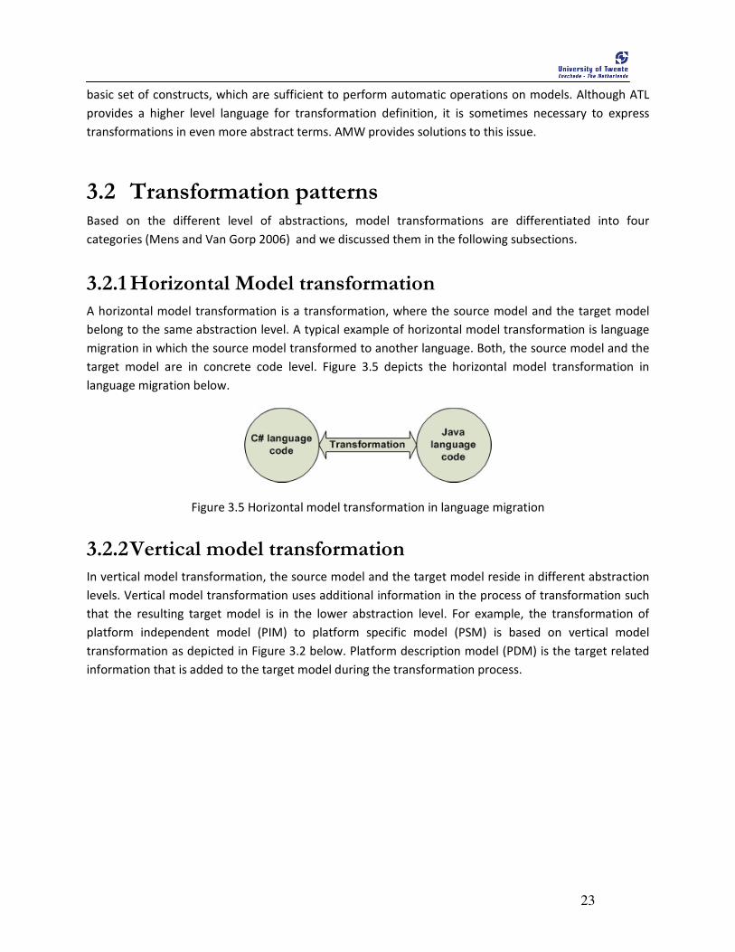
Figure 3.5 Horizontal model transformation in language migration ………………………………………………..23
Figure 3.6 Vertical model transformation from PIM to PSM ……………………………………………………………24
Figure 4.1 Sequence diagram of purchase order ……………………………………………………………………………..28
Figure 4.2 Collaboration diagram representing the choreography ………………………………………………….28
Figure 4.3 Activity diagram of decentralized orchestration ……………………………………………………………..29
Figure 4.4 Sequence diagram for centralized processing …………………………………………………………………30
Figure 4.5 Collaboration diagram representing the choreography with manufacturer ……………………30
Figure 4.6 Activity diagram for the centralized orchestration ………………………………………………………….31
Figure 4.7 Architectural view of choreography and orchestration …………………………………………………..33
Figure 4.8 Architectural patterns for choreography and orchestration ……………………………………………35
Figure 4.9 Diagrammatic representation of transformation from choreography to centralized
orchestration ………………………………………………………………………………………………………………………….………37
Figure 4.10 Diagrammatic representation of transformation from choreography to decentralized
orchestration ………………………………………………………………………………………………………………………….………38
Figure 5.1 WS-CDL package .………………………………………………………………………………………………….………..42
Figure 5.2 Partial illustration of CDL constructs ……………………………………………………………………….………43
Figure 5.3 CDL model of PurchaseOrder example in Pi4soa CDL editor .………………………………….………44
Figure 5.4 Activities of PurchaseOrder modeled in Pi4soa …………………………………………..………….………45
Figure 5.5 Metamodel for root choreography package ….……………………………………………………….………47
Figure 5.6 Metamodel for collaborating participants constructs ……………………………………………………..50
Figure 5.7 Metamodel of the Information Driven collaboration ………………………………………………………54
Figure 5.8 Metamodel of the activity constructs ………………………………………………………………………….….58
Figure 5.9 WS-CDL metamodel ……………………………………………………………………………………………………….59
Figure 6.1 Activity diagram of the Manufacturing process of the purchaseOrder scenario ……………..62
Figure 6.2 Metamodel of WS-BPEL process definition …………………………………………………………………….65
Figure 6.3 Metamodel of basic activities of BPEL ………………………………………………………………..……….….68
Figure 6.4 Metamodel of structured activities ……………………………………………………………………….……....70
Figure 6.5 Metamodel of event handling, fault handling and compensation ……………………….………...71
Figure 6.6 WS-BPEL metamodel ……………………………………………………………………………………..……………..72
Figure 7.1 CDL-to-BPEL metamodel transformation approach .……………………………………………………….75
Figure 7.2 Transformation chain for CDL-to-BPEL transformation .………………………………………………….76
Figure 7.3 Implementation Procedure …………………………………………………………………………………………….82
Figure 7.4 XMI file generation of second stage ……………………………………………………………………………….83
Figure 7.5 XML metamodel adapted from AM3 zoo ………………………………………………………………………..85
Figure 8.1 ActiveBPEL process of ManufacturerDept process ………………………………………….………………94
Figure 8.2 BTO case study(Rosenberg, Enzi et al. 2007) .….………………………………………………………………95
Figure 8.3 ActiveBPEL process of ManufacturerDept process ………………………………………………….……100

x
Figure 8.4 Transformation process of (Mendling and Hafner 2008) .……………………………………….……102
Figure 8.5 system architecture of transformation process of (Rosenberg, Enzi et al. 2007) ………….103
Figure 8.6 The transformation process of (Weber, Haller et al. 2008) …………………………………………..104
Tables
Table 1 Difference of choreography and orchestration ……………………………………………………………………17
Table 2 Transformation mapping from CDL to BPEL ………………………………………………………………………80
Table 3 Comparison among the available approaches …………………………………………………………………..105
xi
Listings
Listing 5.1 Basic language structure of WCDL ………………………………………………………………………………….46
Listing 5.2 Example of choreography package …………………………………………………………………………………46
Listing 5.3 Example of <roleType> construct ……………………………………………………………………………………48
Listing 5.4 Example of <participantType> construct ………………………………………………………………………..48
Listing 5.5 Example of <relationshipType> construct ………………………………………………………………………49
Listing 5.6 Example of <channelType> construct …………………………………………………………………………….49
Listing 5.7 Example of <informationType> construct ……………………………………………………………………….51
Listing 5.8 Example of <token> and <tokenLocator> ...…………………………………………………………………….51
Listing 5.9 Example of variables ...……………………………………………………………………………………………………51
Listing 5.10 Syntax of <workunit> construct .………………..…………………………………………………………………51
Listing 5.11 Syntax of <exceptionBlock> construct .………………..………………………………….…………………..52
Listing 5.12 Syntax of <finalizerBlock> construct …………………..………………………………….…………………….52
Listing 5.13 Syntax of <choreography-Notation> ……………………………………………………….……………………53
Listing 5.14 Example of <sequence> and <choice> constructs .………………………………….……………………55
Listing 5.15 Example of <interaction> construct ….………………..………………………………….…………………….55
Listing 5.16 Syntax of <perform> construct …………………..………………………………….……………………………53
Listing 5.17 Syntax of <silentAction> and <noAction> constructs ……………………..……………………………56
Listing 5.18 Syntax of <assign> construct …..………………..………………………………….………………………………57
Listing 6.1: Language syntax of BPEL …………………..………………………………….……………………………………….63
Listing 6.2 Example of <process> and <partnerLink> constructs ....……….…………………………………………65
Listing 6.3 Example of the process variables and data flow ..…………………………………………………………..66
Listing 6.4 Example of basic activities ……………………………………………………………………………………………..67
Listing 6.5 code sample of structured activities ………….…………………………………………………………………..68
Listing 6.6 Example of <if-else> construct ………………….…………………………………………………………………..69
Listing 6.7 Syntax of <faultHandlers> construct ………….…………………………………………………………………..71
Listing 7.1 Code snippet ATL file of AM3 transformation (T3) ….……………………………………………….…….86
Listing 7.2 Partial BPEL (XMI) model specification ……………………………………………………………………………86
Listing 7.3 Output of the ATL code of Listing 7.1 in ATL engine ..……………………………………………………..86
Listing 7.4 Code snippet of ant file to show AM3 extractor usages ..………………………………………………..87
Listing 7.5 BPEL (XML) file after the execution of ant file …………………………………………………………………87
Listing 8.1 ManufacturerDept.bpel of PurchaseOrder application scenario ..…………………………………..92
Listing 8.2 ManRoleType.bpel of BuildToOrder application scenario ………………………………….……………96
xii
Abbreviations
B2Bi Business-To-Business Integration
SOC Service-Oriented Computing
M2M Model-To-Model
MDA Model-Driven Architecture
SOA Service-Oriented Architecture
ATL ATLAS Transformation Language
QVT Query/View/Transformation
WSCDL Web Service Choreography Description Language
WSBPEL Service Business Process Execution Language
WS Web Services
CORBA Common Object Request Broker Architecture
SCA Service Component Architecture
EJB Enterprise JavaBeans
XML eXtensible Markup Language
WSDL Web Service Description Language
UDDI Universal Description, Discovery and Integration
W3C World Wide Web Consortium
BPMN Business Process Model and Notation
BPD Business Process Diagram
OMG Object Management Group
WSFL Web Service Flow Language
MMM Meta-MetaModel
MM MetaModel
PIM Platform-Independent Models
PSM Platform-Specific Models
PDM Platform Description Model
MOF Meta-Object Facility
OCL Object Constraint Language
AMW ATLAS Model Weaving
ATL VM ATL Virtual Machine
UML Unified Modeling Language
BPSS Business Process Specification Schema
XSLT eXtensible Stylesheet Language Transformation
CCA Component collaboration Architecture
EDOC Enterprise Distributed Object Computing
SLA Service Level Agreement
FSM Finite State Machine
XMI XML Metadata Interchange
AM3 AtlasMega Model Management
GMT Generative Modeling Technologies
MDE Model-Driven Engineering
OASIS Organization for the Advancement of Structured Information Standards
BTO Build-To-Order
KB Knowledge Base
EMF Ecore Modeling Framework

xiii


1
1 Introduction
his chapter provides the introduction of this research in which we propose a model-driven approach to transform a service choreography to a set of related service orchestrations. This chapter presents the motivation, objective, approach, and overall
structure of this thesis. This chapter is structured as follows: Section 1.1 motivates and gives the background for the research. Section 1.2 presents the main objective of the research along with research questions. Section 1.3 presents the research approach that we adopt to achieve the objective. Finally, Section 1.4 presents the overall structure of this thesis.
1.1 Motivation Recently, rapid advances in the Internet technologies have enabled cross-organizational business-to-
business integration (B2Bi). However, B2Bi among multiple enterprises is influenced by various aspects
like mergers, globalization, and changes in policies and technologies (Kavakli and Loucopoulos 1999). In
order to reflect these changes in business environments, changes in organizational structures, and to
stay competitive in the market, business enterprises must adapt their business processes accordingly.
With this evolving business needs, various new collaborations with other organizations need to be
established or existing collaborations need to be updated or terminated.
Service-Oriented Computing (SOC) is one of the promising and emerging technologies to realize the
automatic support to manage such evolving business needs in collaborative business. The fundamental
concept for application development in SOC is the concept of service. According to (Papazoglou 2008),
services are “self-contained, platform-agonistic computational elements that support rapid, low-cost and
easy composition of loosely coupled distributed software applications”. A service can provide standard
functionality to meet a business goal, on its own or by aggregating other existing services. This
aggregation of other existing services results in a composite service with added functionalities. The
process of aggregating a composite service from the existing services is known as service composition
(Chakraborty, Perich et al. 2002). Service composition accelerates application development and enables
service reuse (Milanovic and Malek 2004). Service composition is a complex and challenging task
(Dustdar and Schreiner 2005), in which first the appropriate services have to be discovered, then
selected according to the user’s requirements, and then composed.
Selected services can be composed at different abstraction levels. At a higher abstraction level, a service
composition is viewed as the message exchanges among the participating services. At this abstraction
level, the primary purpose of service composition is to determine what added-value can be realized
instead of how it can be realized. To achieve the added-value from the service composition, we initially
design an abstract specification, which describes public message exchanges, rules of interaction, and
agreements between the participating services. Such an abstract specification that defines the public
message exchanges, rules of interaction, and agreements between the participating services is called
service choreography (Peltz 2003; Barros, Dumas et al. 2006). A choreography is comparable to the
T
2
specification of a business process that specifies what is to be done to achieve a goal. At a lower
abstraction level, it is necessary to define how the added-value of the composite service can be achieved
in terms of a concrete implementation. The concrete implementation that realizes the choreography is
called a service orchestration. We identify two situations in which orchestration can be applied: 1.
implementation of individual services, or 2. Implementation of a central component that coordinates
the overall composition process. In the later case, the central component is called an orchestrator. A
service orchestration defines an execution flow that contains sequences and conditions with which one
service interacts with other services, the control flow, and the data transformations (Peltz 2003; Daniel
and Pernici 2006). Such an execution flow can then be executed by an orchestration engine. A
choreography represents the high level requirements in the early stage of service composition. An
orchestration provides the single party contribution to the service composition.
In business collaborations, the participating organizations may not want to share the internal details of
the services they provide to other organizations, but still they need to leverage sufficient information for
collaboration. In this regard, choreographies provide the sufficient information needed for
collaboration, and the details of the services are implemented in orchestrations. So, based on the
choreography, the detailed behaviors of the orchestrations have to be defined that contributes in
realizing the common business goal. While doing so, orchestrations must be a correct implementations
of the corresponding choreographies (Quartel and van Sinderen 2007). In other words, the
implementation details of the related orchestrations should conform to the given choreography.
In a service composition process, a choreography provides an abstract specification to achieve a
common business goal, and orchestration provides execution details needed to realize the goal.
Therefore, an approach is needed to transform a given choreography to a set of related orchestrations.
Current practices of transforming from choreography to a set of related orchestrations are mostly
manual (Kopp and Leymann 2008), which can become a time consuming, error prone and tedious task in
situations where large number of parties are involved in a choreography. So, we need a (semi-)
automated process of transformation from choreography to orchestration.
This research focuses on generating a set of orchestrations from a given choreography specification in
order to realize service composition. In this research, we propose a model-driven solution to transform
a given choreography to a set of orchestrations. We present how our proposed solution can be used to
correctly implement the behavior of the set of related orchestrations based on the choreography, such
that the common business goal is preserved.
1.2 Research Objective We state the main objective of our research as:
To assess the suitability of model-driven techniques to support service composition starting from
service choreography and ending at service orchestrations.
In order to achieve the main objective of our research, we formulate the following specific research
questions and attempt to answer those questions in this research.

3
RQ1: What are the possible views through which we can realize service composition?
The research is focused on the concept of service composition and its different viewpoints
namely: 1. Service choreography, and 2. Service orchestration. In order to realize the service
composition, each view has its own role. So, we want to investigate these different views of
service composition and find how they complement with each other to realize the service
composition.
RQ2: What are the architectural relationships between choreography and orchestration?
The main motivation of the research is to transform from choreography to set of related
orchestrations. Before designing and implementing this transformation, we aim to investigate the
relationships between choreography and orchestration in architectural level rather than language
level. Such an architectural relationship between choreography and orchestration will enable us to
define transformation that is independent of any choreography and orchestration specification
languages.
RQ3: How can we achieve transformations from a choreography to a set of related orchestrations?
Based on the architectural relationships, we aim to formulate possible architectural patterns
between choreography with orchestration. These patterns can then be used to derive the
transformation specifications.
RQ4: What are the available model-to-model transformation approaches with which we can transform
a choreography to orchestrations?
Our approach adopts model-driven techniques to transform from a choreography to a set of
related orchestrations. So, we explore the model-driven approach and investigate the available
model transformation approach that suitably fits in our proposed solution.
RQ5: How can we combine the views of service composition and model-driven transformation
techniques to realize model-driven development of service composition?
This is one the main contributions of our research. We aim to combine the service composition
and model-driven transformation approach such that we can achieve transformation from
choreography to orchestration. Hence, we investigate how we can integrate two different
domains (i.e., service and modeling domain) to realize the model-driven development of service
composition.
RQ6: How feasible is it to use model-driven technique for transformation from choreography and
orchestrations?
We also discuss how successful our approach is to transform a choreography into set of
orchestrations, such that the common business goal of the choreography is preserved in the
generated orchestration. We compare our approach with the existing developments that also aim
at transforming choreography to orchestration.
1.3 Research Approach In this research, we adopt the research and design methodology principles proposed by (Wieringa 2008;
Wieringa 2009). We illustrate our research approach in Figure 1.1.
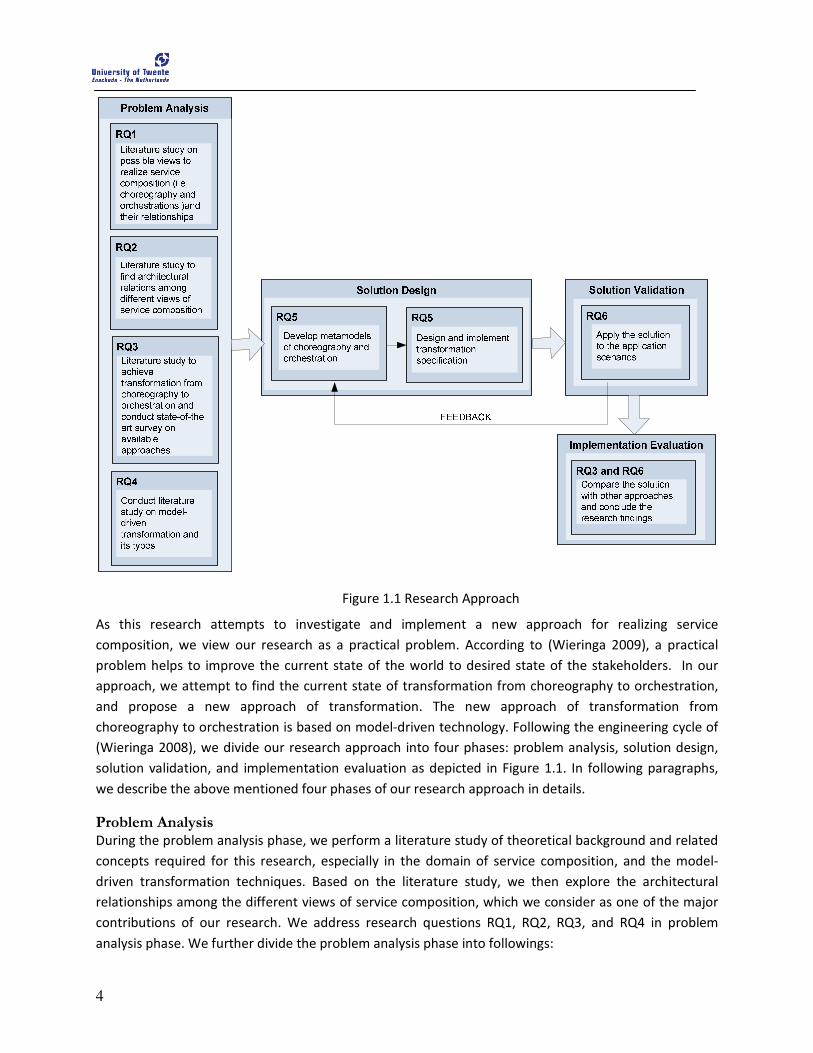
4
Figure 1.1 Research Approach
As this research attempts to investigate and implement a new approach for realizing service
composition, we view our research as a practical problem. According to (Wieringa 2009), a practical
problem helps to improve the current state of the world to desired state of the stakeholders. In our
approach, we attempt to find the current state of transformation from choreography to orchestration,
and propose a new approach of transformation. The new approach of transformation from
choreography to orchestration is based on model-driven technology. Following the engineering cycle of
(Wieringa 2008), we divide our research approach into four phases: problem analysis, solution design,
solution validation, and implementation evaluation as depicted in Figure 1.1. In following paragraphs,
we describe the above mentioned four phases of our research approach in details.
Problem Analysis During the problem analysis phase, we perform a literature study of theoretical background and related
concepts required for this research, especially in the domain of service composition, and the model-
driven transformation techniques. Based on the literature study, we then explore the architectural
relationships among the different views of service composition, which we consider as one of the major
contributions of our research. We address research questions RQ1, RQ2, RQ3, and RQ4 in problem
analysis phase. We further divide the problem analysis phase into followings:
5
1. State-of-the art
Initially, we conduct a literature study on service composition that includes the
consideration of choreography and orchestrations as different views of service composition.
This answers our research question RQ1. We then introduce the concepts of model-driven
transformation, as suggested by Model-Driven Architecture (MDA) (Miller and Mukerji
2003). We also study various types of transformations patterns that are relevant to
transform choreographies into orchestrations. This study answers our research question
RQ4 and we report the results in Chapter 2 and 3 respectively. Additionally, we also present
the current approaches that transform choreographies to orchestrations.
2. Architectural patterns
We identify the possible architectural relationships among choreographies and
orchestrations and present them as architectural patterns. We consider architectural
patterns as one of our major contributions. The aim of the architectural patterns in this
research is to investigate and establish the relationships between choreography and
orchestration at an architectural level. We also use the architectural patterns to explain how
the choreography is comparable to the specifications of business process, and
orchestrations are comparable to the implementations of these business processes. The
architectural patterns answer the research questions RQ2 and RQ3. We report the results in
Chapter 4. We also introduce an application scenario and use the application scenario
throughout this thesis to exemplify choreography and orchestration. The application
scenario also helps us to determine the requirements for the transformation.
Solution Design During the solution design phase, we adopt the model-driven transformation approach to transform the
choreography to a set of orchestrations and we call this model-driven service composition approach. In
order to realize model-driven service composition, we develop concrete metamodels of choreography
and orchestration. Rather than developing the metamodels from scratch, we review the available
metamodels, if there are any, of choreographies and orchestrations and adapt them if necessary. We
then develop the transformation specifications and mappings between the metamodels of
choreographies and orchestrations. These specifications and mappings are used to develop
transformation rules. We implement the transformation rules in a transformation language and hence
realize the transformation. In the solution design phase, we address research question RQ5 and report
the result in Chapter 5, 6, and 7 respectively.
Solution Validation During the solution validation phase, we apply our proposed solution to two application scenarios to
validate the result of the research. We initially validate our proposed solution using the application
scenario introduced in architectural patterns. We also apply our proposed solution to another
application scenario adopted from one of the related works. In the solution validation phase, we
partially address the research question RQ6 and we present the validation results in Chapter 8.
6
Implementation Evaluation During the implementation evaluation phase, we evaluate our approach with three developments
reported in the literature that are closely related to our work. We compare the findings of these
developments in a table to summarize and give the overview of these different approaches. Finally, we
conclude our research by indicating its limitations and the topics for future work. In the implementation
evaluation phase, we answer the research question RQ3 and RQ6. We present the results in Chapters 8
and 9.
1.4 Thesis Structure This thesis is further structured as follows:
Chapter 2: Service Modeling
This chapter gives the theoretical background and the related concepts of Service-Oriented Architecture
(SOA). We briefly explain SOA and Web Services. We then explain the concept of service composition
and introduce choreography and orchestrations as different views of service composition. In this
chapter, we also introduce the generic properties of choreography and orchestration and discuss the
commonality and differences between them.
Chapter 3: Model-Driven Transformation
This chapter introduces the approaches and techniques of model-driven transformation that are defined
in the context of Model-Driven Architecture (MDA) (Miller and Mukerji 2003). We start this chapter
with the introduction of model transformation, and we present the different architectural
transformations patterns described in (Mens and Van Gorp 2006). We also explain two prominent
transformation languages, namely ATLAS Transformation Language (ATL) (Jouault and Kurtev 2007) and
Query/View/Transformation (QVT) (OMG/QVT 2008) to provide a brief introduction of each
transformation languages. After introducing necessary theoretical background for the research, we
discuss the related work on transformation from choreographies to orchestrations.
Chapter 4: Architectural Patterns
This chapter presents the application scenario, which we use to exemplify the concepts of
choreography, orchestration, and their relationships. Based on the architectural relationships, we
develop architectural patterns. We identified two possible situations with which we can transform a
choreography to as set of orchestrations. Based on the architectural patterns, we derive transformation
specifications for the transformation from choreography to both possible variants of orchestrations.
Chapter 5: Modeling service choreography
This chapter describes the metamodel for choreography that we used in our work. We choose Web
Service Choreography Description Language (WS-CDL or CDL in short) (Kavantzas, Burdett et al. 2005) as
choreography specification language and develop metamodel for CDL. In this chapter, we explain the
language constructs of CDL by using the choreography specification derived from application scenario as
an example.
7
Chapter 6: Modeling service orchestration
This chapter presents Web Service Business Process Execution Language (WS-BPEL or BPEL in short)
(Alves, Arkin et al. 2007) as orchestration specification language and we develop metamodel of BPEL.
While exploring the BPEL metamodel, we use an example of BPEL process that is derived from the
application scenario.
Chapter 7: CDL-to-BPEL Transformation
This chapter presents the CDL-to-BPEL transformation mappings between the language elements of CDL
and BPEL that are derived from the transformation specifications. We use these transformation
mappings to develop transformation rules in the ATL language. We also present the implementation
procedure as a proof-of-concept that transforms a given CDL specification to a BPEL process. The
transformation procedure also explains the various transformations that are needed to realize the core
CDL-to-BPEL transformation.
Chapter 8: Validation and Evaluation
This chapter presents the evaluation of the results of our approach by validating our approach with the
application scenarios. Initially, we validate our approach using the application scenario introduced in
Chapter 4. Later, we validate another application scenario that is adopted from one of the related
works. Further, we compare and evaluate our approach with other three closely related developments
that aim to transform a CDL specification to BPEL process.
Chapter 9: Conclusion
This chapter summarizes the overall findings of our research. In this chapter, we conclude the research
by answering the research questions based on our results. We also discuss the scientific contribution of
our research. Finally, we recommend the possible directions for future work based on the limitations of
our current approach.

8
9
2 Service Modeling
his chapter describes the relevant body of knowledge about the concepts used in this research in the context of SOA.
This chapter starts with Section 2.1 that introduces SOA, and Web Services as one of the promising implementation technologies of SOA. Section 2.2 explains the service composition, followed by the explanation of service choreography and service orchestration in Sections 2.3 and 2.4 respectively. We provide the generic properties of service choreography and service orchestration in the same sections and discuss some of the available language specifications of service choreography and service orchestrations. Section 2.5 compares the choreography and orchestration.
2.1 SOA and Web Services SOA is an emerging computing paradigm for building software applications that uses services available
in a network such as the web. SOA promotes the development of loosely-coupled, location transparent
and standard-based distributed software applications in order to alleviate the problem of heterogeneity,
interoperability and business agility (Papazoglou and van den Heuvel 2007). The main concept behind
SOA is a service. A service is self-contained software modules capable of realizing well-defined business
functionality. Services can be consumed by other parties in different applications or business processes.
A remarkable aspect of SOA is that there is an explicit separation of service specification and service
implementation. This separation enables the clients to use the services regardless of the platform of
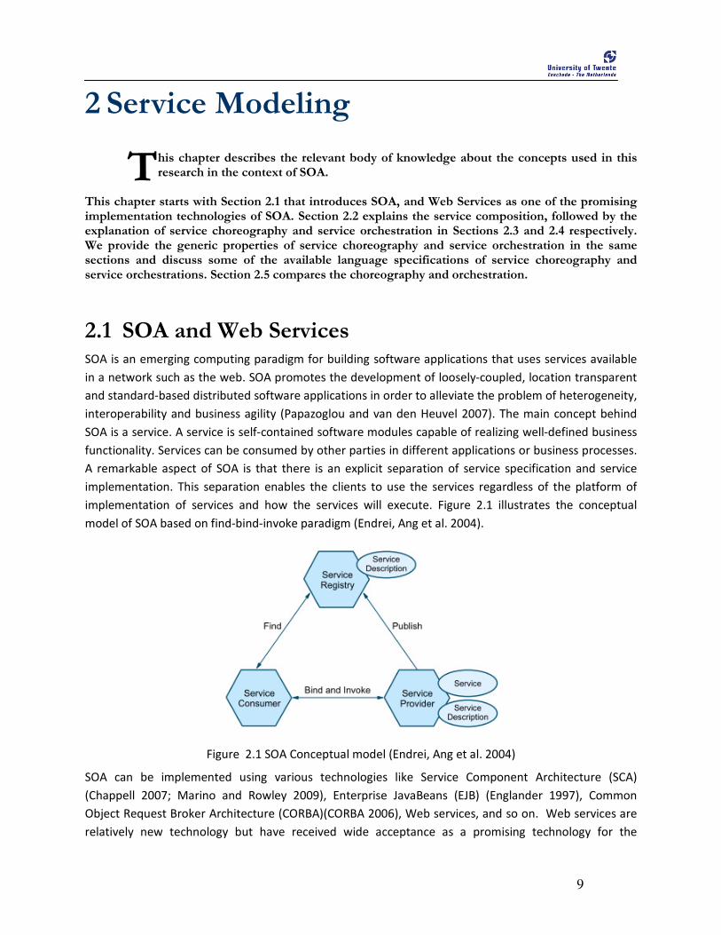
implementation of services and how the services will execute. Figure 2.1 illustrates the conceptual
model of SOA based on find-bind-invoke paradigm (Endrei, Ang et al. 2004).
Figure 2.1 SOA Conceptual model (Endrei, Ang et al. 2004)
SOA can be implemented using various technologies like Service Component Architecture (SCA)
(Chappell 2007; Marino and Rowley 2009), Enterprise JavaBeans (EJB) (Englander 1997), Common
Object Request Broker Architecture (CORBA)(CORBA 2006), Web services, and so on. Web services are
relatively new technology but have received wide acceptance as a promising technology for the
T
10
implementation of SOA. The wide acceptance of Web services is due to the fact that Web services
provide a distributed computing approach in which the applications can be published and accessed over
the Internet for integration of application, and rapid application development (Papazoglou 2008).
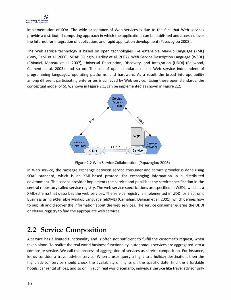
The Web service technology is based on open technologies like eXtensible Markup Language (XML)
(Bray, Paoli et al. 2000), SOAP (Gudgin, Hadley et al. 2007), Web Service Description Language (WSDL)
(Chinnici, Moreau et al. 2007), Universal Description, Discovery, and Integration (UDDI) (Bellwood,
Clement et al. 2003), and so on. The use of open standards makes Web service independent of
programming languages, operating platforms, and hardware. As a result the broad interoperability
among different participating enterprises is achieved by Web service. Using these open standards, the
conceptual model of SOA, shown in Figure 2.1, can be implemented as shown in Figure 2.2.
Find
Publish
Figure 2.2 Web Service Collaboration (Papazoglou 2008)
In Web service, the message exchange between service consumer and service provider is done using
SOAP standard, which is an XML-based protocol for exchanging information in a distributed
environment. The service provider implements the service and publishes the service specification in the
central repository called service registry. The web service specifications are specified in WSDL, which is a
XML-schema that describes the web services. The service registry is implemented in UDDI or Electronic
Business using eXtensible Markup Language (ebXML) (Carnahan, Dalman et al. 2001), which defines how
to publish and discover the information about the web services. The service consumer queries the UDDI
or ebXML registry to find the appropriate web services.
2.2 Service Composition A service has a limited functionality and is often not sufficient to fulfill the customer’s request, when
taken alone. To realize the real world business functionality, autonomous services are aggregated into a
composite service. We call this process of aggregation of services as service composition. For instance,
let us consider a travel advisor service. When a user query a flight to a holiday destination, then the
flight advisor service should check the availability of flights on the specific date, find the affordable
hotels, car rental offices, and so on. In such real world scenario, individual service like travel advisor only
11
cannot fulfill the goal of the user. So, individual services like travel advisor, flight reservation service, and
hotel reservation service, etc are aggregated in order to confirm the overall travel package. Service
composition is not only used for realizing a composite service, but it also accelerates application
development, and enables reuse of existing services (Milanovic and Malek 2004).
Prior to service composition, candidate services should first be discovered and then selected based on
user requirements. The service discovery process results in finding a number of functionally similar
services, and candidate services are selected according to non-functional criteria like cost, availability,
reputations, and so on (Esfandiari and Tosic 2004). In this research, we assume that the appropriate
services are already discovered and selected for service composition.
The service composition process can be considered at different abstraction levels namely choreography
and orchestration (Peltz 2003; Barros, Dumas et al. 2006). The following sections explain choreography
and orchestration in detail.
2.2.1 Service Choreography A choreography describes the public message exchanges, rules of interaction, and the agreements
between the participating services at the initial phase of service composition. It is the decentralized
perspective that specifies how the individual services interact with each other. In this research, we
adopt the definition of choreography from W3C’s Web Service Choreography Working Group (Austin,
Barbir et al. 2004), which defines choreography as “the definitions of the sequences and conditions under
which multiple cooperating independent agents exchange message in order to perform a task to achieve
a goal state”.
A choreography does not describe any internal actions of the participating services that include internal
computations and/or data transformations. A choreography captures message exchanges from a global
and decentralized perspective where all the participating services are treated equally. A choreography is
comparable to a business specification of the business processes. It provides a convenient starting point
that specifies how the participating services must interact to realize a common business goal. At this
abstraction level, the interactions among each service participating in the composition are described as
a global protocol, which all participating services should follow.
We identify some of the requirements for choreography definition language that are useful to
understand the concepts of choreography and eventually help us to develop the metamodel of
choreography. The requirements are as follows:
• Reusability
The same choreography definition can be used by different participants operating in different
contexts with different software. So, a choreography definition language should support the
concept of reuse.
12
• Cooperative
Choreographies define the sequence of message exchanges between participating services by
describing how they should cooperate.
• Multi-Party
Choreographies can be defined involving any number of participating services. So, a
choreography definition language should support multi-party interaction.
• Composability
Existing choreographies can be combined to form new choreographies that may be reused in
different contexts. So, a choreography definition language should support the composition of
the existing choreographies and reusing those composed choreographies.
• Information-Driven
Choreographies describe how participating services maintain their information contents when
they are participating in the choreography by recording the state changes caused by message
exchanges and their reactions to them.
• Information-Alignment
Choreographies allow participants to communicate and synchronize their states and the
information they share.
• Transactional Support
The participants can work in a "transactional“ way with the ability to specify how transactions
are compensated. So, a choreography definition language should be able to compensate in case
if any failures in the course of message exchange occurs.
• Exception Handling
In case of complex message exchanges, there is a possibility of failures due to exceptional and
undesirable circumstances. The exceptional and undesirable scenarios could be connection
failures, time out errors or application errors to name a few. In such an undesirable situations, a
choreography should support exception handling mechanism
• Compatibility with other Specifications
The choreography specifications shall work alongside and complement other specifications such
as WS Reliability, WS Security, WS Business Process Execution Language, etc. So, a choreography
definition language should comply with other WS specifications.
• Design Time Verification
A developer of a business process can use the choreography definition on their own to:
� generate a behavioral interface that conforms to a BPEL definition describing the
sequence and conditions in which one of the participants in a choreography sends and
receives messages
� verify that a BPEL definition conforms to behavior defined in a choreography definition
• Run Time Verification
The performance of a choreography can be verified at run time against the choreography
definition to ensure that it is being followed correctly. If errors are found then the choreography
can specify the action that should be taken
13
• Control flows
A choreography should also support various control flows such that message exchanges among
the participating services can be expressed. It can include flows which support parallel message
exchanges, ordering and sequencing of message exchanges, composition of choreographies
itself.
In the following sections, we briefly describe some of the language specification for service
choreography.
• WS-CDL
WS-CDL (CDL in short) (Kavantzas, Burdett et al. 2005) is an XML-based language that describes
peer-to-peer collaborations of parties by defining, from a global viewpoint, their common and
complementary observable behavior; where ordered message exchange results in
accomplishing a common business goal. CDL is aimed at being able to precisely describe
message exchanges between participating services regardless of the supporting platform or
programming model used by the implementation of the running environment. It is neither an
“executable” nor an “implementation” language. CDL allows specifying the choreographies in
declarative way. CDL also fulfills most of the requirements of choreography specification
language that we identified above so we choose CDL as the specification language to describe
choreography in our research. We explain the details of the constructs of CDL in Chapter 0 while
developing the metamodel of CDL.
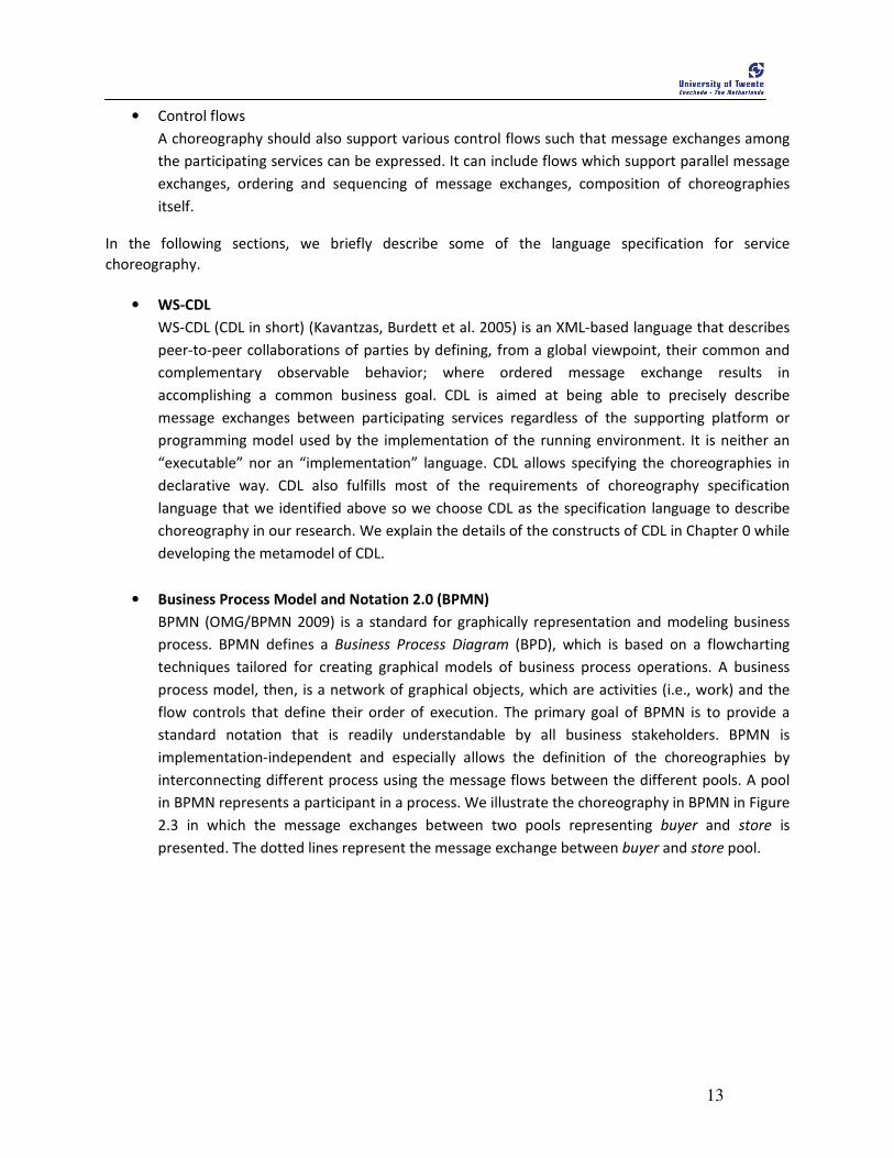
• Business Process Model and Notation 2.0 (BPMN)
BPMN (OMG/BPMN 2009) is a standard for graphically representation and modeling business
process. BPMN defines a Business Process Diagram (BPD), which is based on a flowcharting
techniques tailored for creating graphical models of business process operations. A business
process model, then, is a network of graphical objects, which are activities (i.e., work) and the
flow controls that define their order of execution. The primary goal of BPMN is to provide a
standard notation that is readily understandable by all business stakeholders. BPMN is
implementation-independent and especially allows the definition of the choreographies by
interconnecting different process using the message flows between the different pools. A pool
in BPMN represents a participant in a process. We illustrate the choreography in BPMN in Figure
2.3 in which the message exchanges between two pools representing buyer and store is
presented. The dotted lines represent the message exchange between buyer and store pool.
14
Figure 2.3 Example of choreography in BPMN 2.0
2.2.2 Service Orchestration When the message exchanges among the services are defined to achieve a common business goal, then
it is necessary to define how we can achieve that goal in terms of concrete implementation. Such a
concrete implementation, which describes message exchanges and the internal actions like data
transformations or internal service module invocations, is called orchestration. The orchestration can be
implementation per service provider or can be modeled as a central authority that coordinates the
overall process. In both forms, orchestration contributes in service composition from the single
perspective. In this abstraction level, execution orders of the interactions and method invocation of the
implementations also need to be defined. Orchestration contains enough information to enable
execution of business process by an orchestration engine.
We identify some of the requirements for orchestration definition language that can contribute to
develop the metamodels and understand the concepts of orchestration. The requirements are as
follows:
• Data transformation
A service orchestration should handle the data transformation, which includes the initialization
of the variables and also includes the data transformation in the course of process execution.
• Control flows
An orchestration language must support activities for both communicating with other web
services and also the process itself. So, there is a need of various control flows constructs like
sequences, conditional flow, parallel processing, looping etc.
15
• Recursive composition
A process in an orchestration can be represented by the service itself. The process then can
participate in the orchestration process and can be aggregated to a composite service. Hence, to
facilitate the composition process, an orchestration should support recursive composition.
• Exception handlings
The orchestration language, which initiates the composition process, can aggregate external
services that are purely under the control of the third party. There is a possibility of failures due
to exceptional and undesirable circumstances like application errors, or time-out errors. The
composition process must take into account of such scenarios and maintain exceptions and
hence should support exception handling.
• Transaction support and compensation
The composite services are usually long-running processes that may take longer time to
complete, and therefore the ability to manage transactions and compensations over service
invocation is critical for Web services composition. Compensations are needed to rollback the
effects of completed transactions when there is a failure in the enclosed transaction scope.
Hence, an orchestration language should support the transactional support and must be able to
compensate in case of failure.
• Stateful service interaction
In a real B2Bi scenario, multiple instance of the same composite process might be running. It is
important that messages exchanged in between a composite process and the participating
services need to be delivered to the correct instance of the composite process. This mechanism
preserves the stateful service interaction.
• Execution
The orchestration language should be executable i.e. it contains enough information to enable
execution by an orchestration engines such as ActiveBPEL1.
• Compatibility with other Specifications
The orchestration specification works alongside and complements other specifications such as
WS Reliability, WS Security, etc. So, a orchestration definition language should comply with
other WS specifications.
In the following subsections we briefly present some of the available languages for service
orchestration.
• WS-BPEL
WS-BPEL (BPEL in short) (Alves, Arkin et al. 2007) is an XML-based language designed for
coordinating the flow of business process that can specify the business process in a detailed
internal form. BPEL emerged through the consolidation of earlier work on IBM’S Web Service
Flow Language (WSFL) (Leymann 2001) and XLANG (Thatte 2001) developed by Microsoft. BPEL
is one of the widely used service orchestration languages. BPEL fulfills most of the requirements
of orchestration language that we identified above and is also the de-facto standard for
specifying the business process. We choose BPEL as the specification language for orchestration
1 http://www.activevos.com/community-open-source.php
16
in our research. We discuss the BPEL in details in Chapter 6 while developing the BPEL
metamodel.
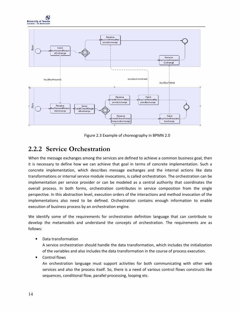
• BPMN 2.0
BPMN 2.0 is also used to model orchestration and it is termed as private business process that is
internal to a specific organization. There are two types of private processes: executable and
non-executable. An executable process is the one that has been modeled for the purpose of
being executed whereas a non-executable process is a private process that has been modeled
for the purpose of documenting process behavior at a modeler-defined level of detail. In BPMN
2.0, orchestration is represented as the process flow with various activities and is contained
within a single Pool. A pool in BPMN represents a participant in a process. Figure 2.4 illustrates
the orchestration in BPMN 2.0 for the store process that contains various activities and
sequences in which those activities are executed.
Figure 2.4 Example of orchestration in BPMN 2.0
2.3 Discussion Based on the definition and the requirements of choreography and orchestration specification
languages provided in earlier sections, we discuss the relationship between choreography and
orchestration.
A choreography and an orchestration are the overlapping viewpoints of service composition (Barros,
Dumas et al. 2006), and complement with each other (Busi, Gorrieri et al. 2005) yet there are noticeable
difference. Both, choreography and orchestration represent the behavior of service composition, but
from different viewpoint.
A choreography and orchestration differs in many aspects. A choreography defines a protocol that
governs the message exchange and reflects “what” business goal is to be achieved. All the participating
services are abided to follow the specification to achieve the goal. A choreography reflects the global
perspective of service composition in which there is no central controller that governs the specification.
An orchestration defines the procedure that states “how” the business goal is achieved. A choreography
deals with the public message exchange between the participating services while a orchestration deals

17
with both public and private message exchanges from the single party perspective. Based on the
common public message exchanges of choreography, we can generate the code skeleton of the
orchestration. The other benefit of choreography is that the public message exchange is visible to the
outer world and hence, can be published with sufficient information that is needed for collaboration. In
contrast, the orchestration contains internal details of the services and hence, may not want to share
these internal details with the outer world. Further, an orchestration needs implementation of service
(running instance of the implementation) to run but choreography does not necessarily need the
implementation of the services.
The most notable difference between choreography and orchestration lies on the nature of
choreography and orchestration. A choreography is descriptive in nature with which we can describe the
behavior of services in composition. In contrast, an orchestration is imperative and contains enough
information to enable execution of business process by an orchestration engine.
From the perspective of composing web services to the execution business processes, an orchestration
has an advantage over choreography. A orchestration has at least the following advantages over
choreography:
• A choreography is inherently design-level artifact while an orchestration is executable artifact.
• An orchestration provides information that identifies who is responsible for the execution of the
business process.
• An orchestration can incorporate web services, even those that are not aware that they are a
part of a business process.
We present the basic differences as summary of comparison between choreography and orchestration
in the Table 1.
Table 1 Differences of choreography and orchestration
Criteria Choreography Orchestration
Mechanism Public message interchange between
the participating services
Public and private message interchanges
between participating services
Coordinator No central coordinator Presence of central coordinator expect
in per service implementation
Execution It is declarative hence cannot be
executed
It is imperative and contains enough
information such that it can be executed
in the orchestration engine
Visibility Message exchange is global so visible to
the outer world
Public message is visible while private
message exchange is not visible to the
outer world
Languages WS-CDL, BPMN 2.0 WS-BPEL, BPMN 2.0

18

19
3 Model-Driven Transformation
n this chapter, we introduce the concepts related with MDA and model transformation that are relevant for this research. We also present the related developments that aim to
transform choreography to orchestration.
The chapter is structured as follows: Section 3.1 introduces the model transformation in the context of MDA. The Subsections 3.1.1 and 3.1.2 briefly present the introduction of two prominent transformation languages: Query/View/Transformation (QVT) (OMG/QVT 2008) and ATLAS Transformation Language (ATL) (Jouault, Allilaire et al. 2008). Section 3.2 describes the transformation patterns that are found in literature of MDA. Based on the available patterns, we identify the most suitable pattern that can address the transformation from choreography to orchestration. Section 3.3 presents the relevant developments that aim to transform a choreography to an orchestration.
3.1 Model transformation MDA is a software design framework which provides a set of guidelines for expressing the software
systems as models (Poole 2001; Kurtev 2005). It was launched by the Object Management Group (OMG)
in 2001. In software development process, the implementation tools and technologies are constantly
changing so there is a problem to port applications to new technology. MDA aims to improve this
problem by specifying software systems using models and then later the implementations are obtained
from model via model transformation. In MDA, Platform-Independent Models (PIM) are initially
expressed in a platform-independent modeling language and then translated to Platform-Specific
Models (PSM) via model transformation.
We illustrate the basic idea of MDA and model transformation using Figure 3.1. The basic entity of the
MDA is Meta-MetaModel (MMM at the Layer M3 that confirms to itself). Using a meta-metamodels of
Layer M3, MetaModels (MM) of Layer M2 can be specified. Metamodels are generally used as the basis
for creating models, which represents the real world entities. The MetaModel Transformation (MMT)
also resides in Layer M2 and conforms to MMM of layer M3. We creates model as an instance of
Metamodels of Layer M2. So, a model in layer M1 conforms to its respective metamodel of Layer M2.
The transformation code is also an instance of MMT of Layer M2 and hence, transformation code also
conforms to the MMT.
I
20
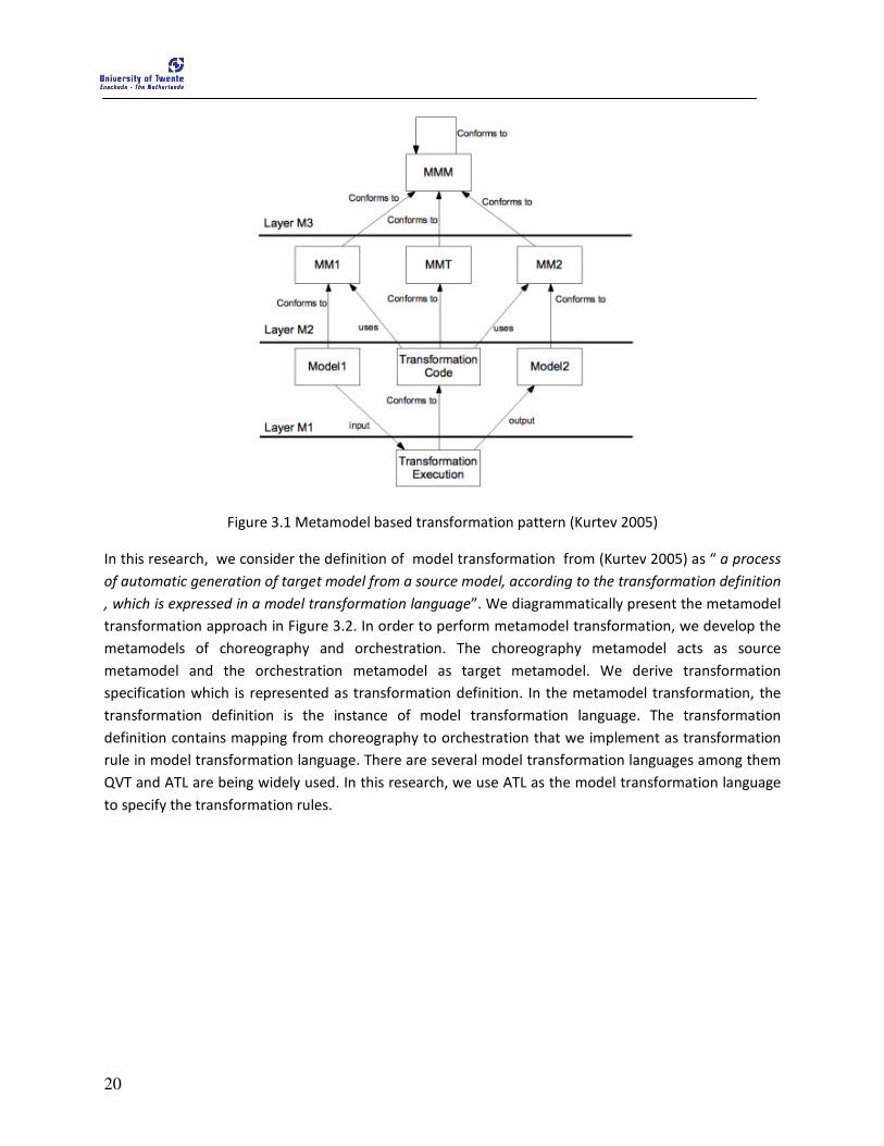
Figure 3.1 Metamodel based transformation pattern (Kurtev 2005)
In this research, we consider the definition of model transformation from (Kurtev 2005) as “ a process
of automatic generation of target model from a source model, according to the transformation definition
, which is expressed in a model transformation language”. We diagrammatically present the metamodel
transformation approach in Figure 3.2. In order to perform metamodel transformation, we develop the
metamodels of choreography and orchestration. The choreography metamodel acts as source
metamodel and the orchestration metamodel as target metamodel. We derive transformation
specification which is represented as transformation definition. In the metamodel transformation, the
transformation definition is the instance of model transformation language. The transformation
definition contains mapping from choreography to orchestration that we implement as transformation
rule in model transformation language. There are several model transformation languages among them
QVT and ATL are being widely used. In this research, we use ATL as the model transformation language
to specify the transformation rules.

21
Figure 3.2 Metamodel transformation (Kurtev 2005)
In next Subsections, we briefly discuss the QVT and ATL transformation languages.
3.1.1 QVT QVT is OMG defined standard for the model transformation language that is capable of expressing
queries, views and transformations over models in the context of Meta-Object Facility 2.0 (MOF 2.0)
metamodeling architecture. QVT relies on Object Constraint Language 2.0 (OCL 2.0) as navigation and
query language for models. QVT languages collectively form a hybrid transformation language with both
declarative and imperative constructs. The architecture of the QVT language is shown in Figure 3.3. As
shown in Figure 3.3, Relations, Core and Operational Mappings are organized in a layered architecture.
Figure 3.3 QVT languages layered architecture
• Relations: It is the declarative transformation language which specifies transformations as a set
of relations over models.

22
• Core: It is also the declarative transformation language which is used to provide basis for
specifying semantics of the Relations language.
• Operational Mapping: It is the imperative transformation language that enriches Relations
language with imperative constructs. It contains traditional control flow constructs like that of
imperative languages.
The Black Box mechanism allows the procedures for calling external programs during transformation
execution.
3.1.2 ATL ATL is a model transformation language developed by OBEO
2 and INRIA
3, which can be specified both as
a metamodel and as a textual concrete syntax (Jouault and Kurtev 2007). ATL also provides both
declarative and imperative constructs and hence, is a hybrid model transformation language. The ATL
architecture is also layered consisting of ATLAS Model Weaving (AMW), ATL, and ATL Virtual Machine
(ATL VM) and is depicted in Figure 3.4.
Figure 3.4 ATL layered architecture
An ATL transformation program is composed of called rules and action block representing the imperative
constructs and matched rules representing the declarative part. The matched rule consists of a source
pattern matched over source models and of a target pattern that gets created in target models for every
match. A called rule is explicitly called but the body of the rule may contain the declarative part. Action
blocks are the sequences of imperative instruction that can be used in either matched or called rules
that define how source model elements are matched and navigated to create and initialize the elements
of the target models.
The execution support of the ATL transformation programs is done by ATL VM. This approach has
several advantages like easy extension of ATL, and cross language compilation. The ATL VM provides a
2 http://www.obeo.fr/pages/atl-pro/en
3 http://modelware.inria.fr/rubrique12.html
23
basic set of constructs, which are sufficient to perform automatic operations on models. Although ATL
provides a higher level language for transformation definition, it is sometimes necessary to express
transformations in even more abstract terms. AMW provides solutions to this issue.
3.2 Transformation patterns Based on the different level of abstractions, model transformations are differentiated into four
categories (Mens and Van Gorp 2006) and we discussed them in the following subsections.
3.2.1 Horizontal Model transformation A horizontal model transformation is a transformation, where the source model and the target model
belong to the same abstraction level. A typical example of horizontal model transformation is language
migration in which the source model transformed to another language. Both, the source model and the
target model are in concrete code level. Figure 3.5 depicts the horizontal model transformation in
language migration below.
Figure 3.5 Horizontal model transformation in language migration
3.2.2 Vertical model transformation In vertical model transformation, the source model and the target model reside in different abstraction
levels. Vertical model transformation uses additional information in the process of transformation such
that the resulting target model is in the lower abstraction level. For example, the transformation of
platform independent model (PIM) to platform specific model (PSM) is based on vertical model
transformation as depicted in Figure 3.2 below. Platform description model (PDM) is the target related
information that is added to the target model during the transformation process.

24
Figure 3.6 Vertical model transformation from PIM to PSM
3.2.3 Endogenous Model transformation In endogenous model transformation, the transformations between the source and the target models
are expressed in the same language. Both the models conform to the same metamodel. For instance,
code optimization is an endogenous model transformation in which the transformation is aimed to
improve certain operational qualities of the system.
3.2.4 Exogenous Model transformation Exogenous transformations are those in which the transformation between source and target models is
expressed in different languages. The source and target models in exogenous transformation conform to
different respective metamodels. For example, code generation is exogenous model transformation in
which lets say a UML class diagram can be translated to Java code.
Choreography and orchestration reside at different abstraction levels. Hence, we use vertical
transformation approach to transform the choreography to orchestration. The transformation uses
choreography specification as input and generates orchestration specification as output. With this
respect, the transformation is exogenous transformation.
3.3 Related work In this section, we briefly mention the research developments that aim to transform choreography to
orchestration.
One of the initial works in the domain of transformation from choreography to orchestration is (Kim and
Huemer 2004) in which Business Process Specification Schema (BPSS), the ebXML standard to specify
choreography, is automatically transformed to BPEL process. The authors only suggest the guidelines for
transformation, but fail to provide any concrete transformation implementation. These guidelines are in
language level so architectural relationships between choreography and orchestration are not discussed.
25
In (Mendling and Hafner 2008), a transformation from CDL to BPEL is presented. The authors describe
the XSLT-based transformation to transform CDL specification to BPEL process. The details mapping
from CDL-based constructs to BPEL-based constructs are provided and is explained using the example
with an application scenario. The transformation is performed in language level.
A formal approach of transformation from CDL to BPEL is reported in (Diaz, Cambronero et al. 2006).
The author devised a way to generate correct BPEL skeleton documents from a given CDL specification.
Initially, the given CDL document is translated to Timed Automata UPPAAL XML format, and then from
Timed-Automata to BPEL-based orchestration. Additionally, to maintain correctness with respect to
timed-automata, restrictions are imposed before translating Timed-Automated UPPAAL XML format to
BPEL. The use of formal techniques in the process of transformation is a noticeable feature, which is
then used to verify the correctness of the transformed BPEL process with respect to time restrictions.
In (Yu, Zhang et al. 2007), a model-driven automatic transformation approach is presented in which
choreography specified in Component collaboration Architecture (CCA) of UML profile for Enterprise
Distributed Object Computing (EDOC) is transformed to BPEL specification using QVT. The notable
feature of the research is that it uses model-driven transformation in which the transformation rules are
specified in Operational mapping language of QVT standard specification. The transformation is
performed in language level.
In (Rosenberg, Enzi et al. 2007), a transformation from CDL to BPEL is presented in which choreography
annotated with Service Level Agreements (SLAs) from the different partners is transformed in BPEL.
Additionally, the SLAs are transformed into policies which can then be enforced by a BPEL engine during
execution. The CDL to BPEL transformation is implemented using the DOM4J API4. The other notable
work in this research is the automatic generation of WSDL files from the choreographies such that the
process can invoke the respective WSDL files while executing. The transformation is performed in
language level.
In (Weber, Haller et al. 2008), a transformation from CDL to BPEL is presented in the context of the
virtual organizations. The challenges that are faced when transforming a choreography to an
orchestration is discussed. The transformation is based to focus on solving the “information gap”
challenges, which represents the difference between the information present in a choreography and an
orchestration. The transformation generates BPEL process and required WSDL files from the CDL.
An automated approach of synthesis of orchestrator from choreography is presented in (McIlvenna,
Dumas et al. 2009) in which choreography specified in BPMN/ BPEL is translated to a BPMN/ BPEL-based
orchestrator. A formal approach of synthesizing orchestrator, where the BPMN/ BPEL based
choreography is represented in Finite State Machine (FSM) is chosen. The synthesizing algorithm that
constructs the orchestrator is developed such that the orchestrator is represented in Petri-nets. The
algorithm includes the methods of verifying correctness of the orchestrator, for instance, detecting and
avoiding deadlock situations. The Petri-net based model is then later transformed to BPMN/ BPEL.
4 http://www.dom4j.org/

26
27
4 Architectural Patterns
his chapter presents an application scenario from which we identify architectural relationships between a choreography and an orchestration. The main aim of this
chapter is to get motivation for the transformation from choreography to orchestration from the previously identified architectural relationships. The architectural relationships are also used to derive architectural patterns. Inspired from the architectural patterns, we also explain the design rationale in which we explain how the transformation of choreography to orchestration can be achieved.
This chapter is structured as follows: Section 4.1 presents the application scenario of a PurchaseOrder system. Section 4.2 presents the architectural patterns of choreography and orchestration. Section 4.3 explains the transformation from choreography to orchestration based on the identified architectural patterns.
4.1 Application Scenario In this application scenario, we present an inter-organizational process, where a purchase order of a
customer is processed. The presented scenario involves various departments: sales department, stock
department, shipment department, and billing department and a customer, who orders good. We
identified two ways of processing the order which are as follow:
1. Decentralized processing: the order is processed in a distributed manner through the
cooperation of the departments (services that support the processing of the order)
2. Centralized processing: the order is processed by a centralized coordinator
Each of these alternatives is explained in following subsections.
4.1.1 Decentralized processing In decentralized processing, we assume that the sales department receives the purchase order from the
customer and acts as the initiator for the processing of the users request. The purchase order is then
forwarded to the stock department, which checks the availability of the good being requested. In case
the requested good is not available, the stock department informs the production department that the
required good should be produced. In order to avoid complexity in the application scenario, we assume
that the stock department has enough stock of goods and we ignore the interaction with the production
department. The stock department then sends the information to the shipping department for the
arrangement of the shipment of the requested good to the customer. Upon arranging necessary
requirements for shipping the requested good, the shipment department contacts the billing
department with the shipping cost and the expected delivery date. Finally, the billing department
calculates the total cost and sends the total cost to the sales department as purchase order response.
T
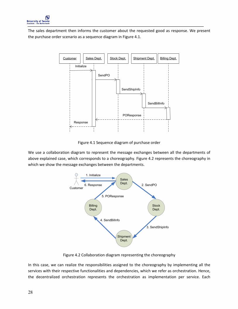
28
The sales department then informs the customer about the requested good as response. We present
the purchase order scenario as a sequence diagram in Figure 4.1.
Sales Dept. Stock Dept. Shipment Dept. Billing Dept.
SendPO
SendShipInfo
SendBillInfo
POResponse
Customer
Initialize
Response
Figure 4.1 Sequence diagram of purchase order
We use a collaboration diagram to represent the message exchanges between all the departments of
above explained case, which corresponds to a choreography. Figure 4.2 represents the choreography in
which we show the message exchanges between the departments.
Stock
Dept.
5. POResponse
4. SendBilInfo
2. SendPO
3. SendShipInfo
Billing
Dept.
Shipment
Dept.
Sales
Dept.
Customer
1. Initialize
6. Response
Figure 4.2 Collaboration diagram representing the choreography
In this case, we can realize the responsibilities assigned to the choreography by implementing all the
services with their respective functionalities and dependencies, which we refer as orchestration. Hence,
the decentralized orchestration represents the orchestration as implementation per service. Each
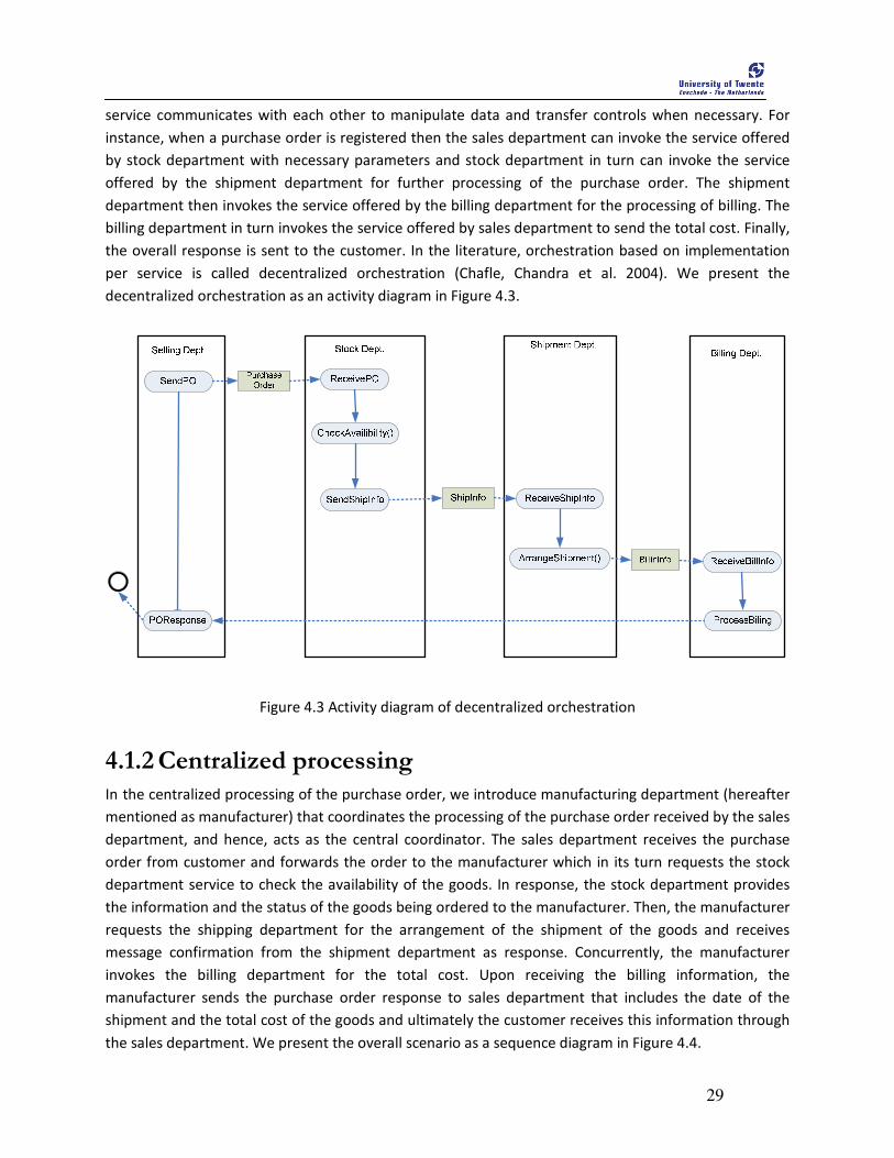
29
service communicates with each other to manipulate data and transfer controls when necessary. For
instance, when a purchase order is registered then the sales department can invoke the service offered
by stock department with necessary parameters and stock department in turn can invoke the service
offered by the shipment department for further processing of the purchase order. The shipment
department then invokes the service offered by the billing department for the processing of billing. The
billing department in turn invokes the service offered by sales department to send the total cost. Finally,
the overall response is sent to the customer. In the literature, orchestration based on implementation
per service is called decentralized orchestration (Chafle, Chandra et al. 2004). We present the
decentralized orchestration as an activity diagram in Figure 4.3.
Figure 4.3 Activity diagram of decentralized orchestration
4.1.2 Centralized processing In the centralized processing of the purchase order, we introduce manufacturing department (hereafter
mentioned as manufacturer) that coordinates the processing of the purchase order received by the sales
department, and hence, acts as the central coordinator. The sales department receives the purchase
order from customer and forwards the order to the manufacturer which in its turn requests the stock
department service to check the availability of the goods. In response, the stock department provides
the information and the status of the goods being ordered to the manufacturer. Then, the manufacturer
requests the shipping department for the arrangement of the shipment of the goods and receives
message confirmation from the shipment department as response. Concurrently, the manufacturer
invokes the billing department for the total cost. Upon receiving the billing information, the
manufacturer sends the purchase order response to sales department that includes the date of the
shipment and the total cost of the goods and ultimately the customer receives this information through
the sales department. We present the overall scenario as a sequence diagram in Figure 4.4.

30
Figure 4.4 Sequence diagram for the centralized processing
The collaboration diagram representing the service choreography of centralized processing of the
purchase order scenario is presented in Figure 4.5.
Figure 4.5 Collaboration diagram representing the choreography with manufacturer
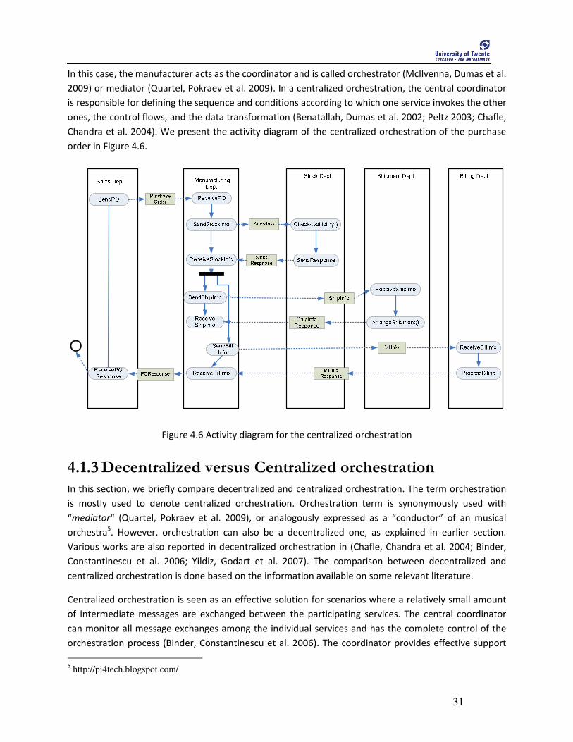
31
In this case, the manufacturer acts as the coordinator and is called orchestrator (McIlvenna, Dumas et al.
2009) or mediator (Quartel, Pokraev et al. 2009). In a centralized orchestration, the central coordinator
is responsible for defining the sequence and conditions according to which one service invokes the other
ones, the control flows, and the data transformation (Benatallah, Dumas et al. 2002; Peltz 2003; Chafle,
Chandra et al. 2004). We present the activity diagram of the centralized orchestration of the purchase
order in Figure 4.6.
Figure 4.6 Activity diagram for the centralized orchestration
4.1.3 Decentralized versus Centralized orchestration In this section, we briefly compare decentralized and centralized orchestration. The term orchestration
is mostly used to denote centralized orchestration. Orchestration term is synonymously used with
“mediator“ (Quartel, Pokraev et al. 2009), or analogously expressed as a “conductor” of an musical
orchestra5. However, orchestration can also be a decentralized one, as explained in earlier section.
Various works are also reported in decentralized orchestration in (Chafle, Chandra et al. 2004; Binder,
Constantinescu et al. 2006; Yildiz, Godart et al. 2007). The comparison between decentralized and
centralized orchestration is done based on the information available on some relevant literature.
Centralized orchestration is seen as an effective solution for scenarios where a relatively small amount
of intermediate messages are exchanged between the participating services. The central coordinator
can monitor all message exchanges among the individual services and has the complete control of the
orchestration process (Binder, Constantinescu et al. 2006). The coordinator provides effective support
5 http://pi4tech.blogspot.com/
32
for fault and error handling because it is easy to locate in which of the participating services the error
has occurred. Further, the coordination of participating services can be easily done since it is the
responsibility of the coordinator to define which service has to be invoked as specified. However, the
central coordinator, being responsible for coordination of all message exchange and the control flows
between the participating services, can result in an ineffective communication, and hence become a
performance bottleneck. Additionally, the central coordinator also has to manage the message
exchanges which are ultimately forwarded to the specific target services for processing. This introduces
unnecessary traffic on the network. It is also possible that a lot of irrelevant intermediatory data can be
generated in the orchestration process which may not be used in the process of computation and are
usually discarded by the central coordinator. These factors can lead to the poor scalability and
performance degradation when huge amount of message exchange occur in the composition (Chafle,
Chandra et al. 2004).
Decentralized orchestration can be effective in scenarios where a huge amount of message exchanges
occur between the participating services. In decentralized orchestration, each service is capable of
handling the message exchanges and the control flows such that it reduces the amount of network
traffic in the orchestration process. Additionally, the decentralized orchestration improves concurrency,
because the control flow can also be distributed among the participating services. This feature can lead
to increased parallelism and reduced network traffic. Decentralized orchestration brings performance
improvements like better response time and throughput to the execution of composite service (Barker,
Weissman et al. 2008). The experimental results of better performance of decentralized orchestration
over centralized orchestration can be found in (Chafle, Chandra et al. 2004; Binder, Constantinescu et al.
2006). Despite the aforementioned benefits, each service in a decentralized orchestration still needs to
coordinate for determining and invoking the next participating service. Decentralized orchestration also
needs additional support for error and fault handling because it is not easy to monitor the progress of
each service invocation. For instance, in our application scenario the customer might either receive the
purchase order response with the billing information if the service composition is performed correctly
else receives an error indication but may not be able to specify in which participant the error has
occurred. Additionally, in order to implement decentralized orchestration, each participating services
needs to introduce an additional orchestration engine, which could be costly and even may adversely
affect the performance of the overall of orchestration (Chafle, Chandra et al. 2004).
4.2 Architectural Patterns We use the purchase order application scenario, presented in Section 4.1, to identify the architectural
relationships between choreography and orchestration and derive the architectural patterns. From the
system design point of view, the architectural relationship between choreography and orchestration can
be explained using Figure 4.7. In this research, we assume that the system requirements (like business
goals) of a composite service are known beforehand and are represented as the responsibility of the
choreography. From the application scenario, we identify two possible ways in which orchestration can
be applied:
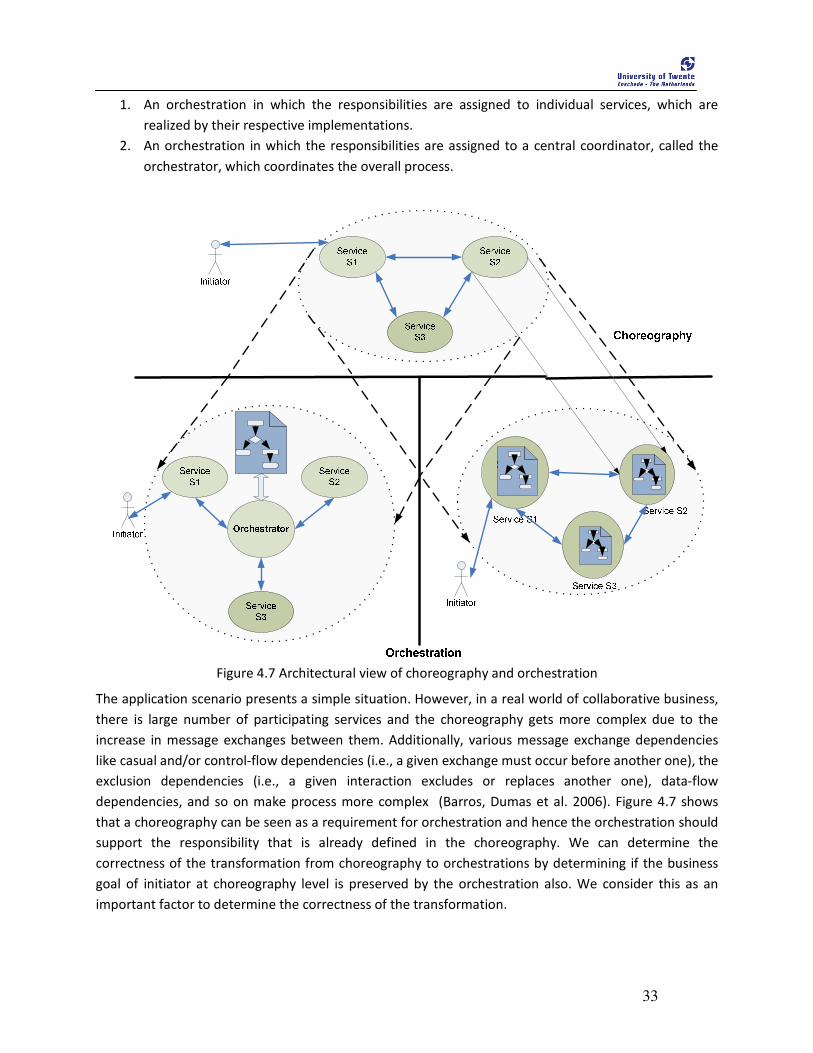
33
1. An orchestration in which the responsibilities are assigned to individual services, which are
realized by their respective implementations.
2. An orchestration in which the responsibilities are assigned to a central coordinator, called the
orchestrator, which coordinates the overall process.
Figure 4.7 Architectural view of choreography and orchestration
The application scenario presents a simple situation. However, in a real world of collaborative business,
there is large number of participating services and the choreography gets more complex due to the
increase in message exchanges between them. Additionally, various message exchange dependencies
like casual and/or control-flow dependencies (i.e., a given exchange must occur before another one), the
exclusion dependencies (i.e., a given interaction excludes or replaces another one), data-flow
dependencies, and so on make process more complex (Barros, Dumas et al. 2006). Figure 4.7 shows
that a choreography can be seen as a requirement for orchestration and hence the orchestration should
support the responsibility that is already defined in the choreography. We can determine the
correctness of the transformation from choreography to orchestrations by determining if the business
goal of initiator at choreography level is preserved by the orchestration also. We consider this as an
important factor to determine the correctness of the transformation.
34
4.3 Choreography to orchestration In a B2Bi, the collaboration between the multiple participating parties can be used to achieve a business
goal through service composition. In a service composition, a choreography provides an abstract
specification to achieve a business goal and orchestration provides execution details needed to realize
the business goal. Therefore, an approach is needed to transform a choreography to a set of
orchestrations. Current practices of transforming from a choreography to a set of orchestrations are
mostly manual (Kopp and Leymann 2008), which can become a time consuming, error prone and
tedious task in situations where large number of parties are involved in a choreography. Our approach
of (semi-) automatic transformation from choreography to orchestration seems advantageous not only
to substantially speed up the development process, but also to minimize the risk of inconsistencies that
could be introduced when the transformation is done manually.
We identified the following potential problems that may be introduced when automating the
transformation of a choreography to an orchestration(s) because of the difference in their abstraction
levels:
a. We may need to add, update, and/or delete information while performing the transformation.
In our approach, if needed, we solve this problem by using the concept of marking (Miller and
Mukerji 2003), which is suggested by the MDA. Marking is the process of information to the
transformation process from source to target model.
b. We see orchestration as a typical refinement of a choreography. In order to preserve correct
behavior of the orchestration and satisfy the request of the end user, orchestration should
conform to the choreography. For instance, let us consider the Figure 4.8, which is the
refinement of Figure 4.7 and depicts two possible orchestrations for the PurchaseOrder
application scenario. The goal of the customer can be realized through the collaboration
between different participants in a way as specified in the choreography. When we perform
transformation, the resulting orchestration should preserve the overall behavior of the system
(i.e., the collaboration between the participants) and should satisfy the request of the customer
as specified in the choreography. Such a conformance of orchestration with respect to a given
choreography has to be preserved. This conformance is defined as choreography conformance
(Quartel and van Sinderen 2007).
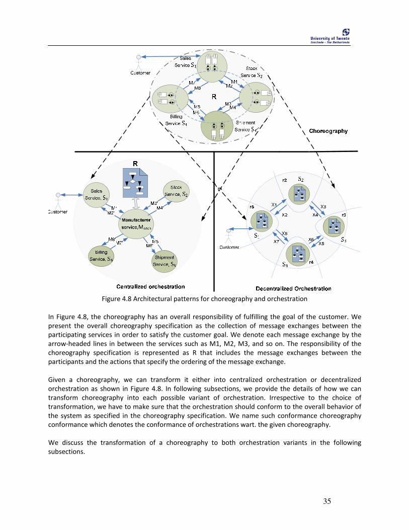
35
Figure 4.8 Architectural patterns for choreography and orchestration
In Figure 4.8, the choreography has an overall responsibility of fulfilling the goal of the customer. We
present the overall choreography specification as the collection of message exchanges between the
participating services in order to satisfy the customer goal. We denote each message exchange by the
arrow-headed lines in between the services such as M1, M2, M3, and so on. The responsibility of the
choreography specification is represented as R that includes the message exchanges between the
participants and the actions that specify the ordering of the message exchange.
Given a choreography, we can transform it either into centralized orchestration or decentralized
orchestration as shown in Figure 4.8. In following subsections, we provide the details of how we can
transform choreography into each possible variant of orchestration. Irrespective to the choice of
transformation, we have to make sure that the orchestration should conform to the overall behavior of
the system as specified in the choreography specification. We name such conformance choreography
conformance which denotes the conformance of orchestrations wart. the given choreography.
We discuss the transformation of a choreography to both orchestration variants in the following
subsections.
36
4.3.1 Choreography to centralized orchestration In this section, we explain how we can transform a given choreography to a centralized orchestration.
We explain this transformation using Figure 4.9, which is the refinement of Figure 4.8 considering the
transformation from choreography to centralized orchestration part only. In the PurchaseOrder scenario
depicted in Figure 4.9, for example when a customer initiates the order, the Sales service, S1 performs its
role as defined in responsibility of choreography R in order to process the order. After processing the
order, S1 exchanges message M1 with Stock service S2 by inquiring the stock status of the ordered good.
S2 performs its role as specified in R, which is to check the status of ordered good and the PurchaseOrder
process continues until the customer receives the response from Sales service. In this way the process
continues and the goal of the customer is fulfilled. Given a choreography in terms of responsibilities and
message exchanges, we aim to derive the transformation specification for the centralized orchestration.
The transformation from choreography to centralized orchestration is achieved by transferring the
overall responsibility of choreography R to the orchestrator and accordingly establishing the message
exchanges between the orchestrator and the individual services. In this transformation, the overall
responsibility of the choreography is projected to the responsibility of a central orchestrator, as
depicted in Figure 4.9 by R. The projection of responsibility includes following tasks:
• The message exchange present in the choreography specification should be preserved in the
responsibility of the centralized orchestrator. In case of choreography, the individual service
communicates with other service as per the requirement of the choreography specification. Let
us consider that the choreography specification contains a message exchange in which a service
(source) sends message to another service (target). Such message exchange can now be
maintained in the centralized orchestrator, first by sending the message from source service to
the orchestrator and then the orchestrator sends it to the target service as per specified in
choreography.
• The responsibility of the orchestrator should also include the coordination mechanism which
preserves the ordering of the message exchange specified in the choreography.
• The responsibility of the orchestrator should also include the error, fault and compensation
handling as specified in the choreography specification.
For instance, in Figure 4.9, the Manufacturer service, Morch act as an orchestrator and the overall
responsibility of the choreography R is transformed as the responsibility of Morch. The message
exchanges between S1 and S2 in choreography have to be performed in two steps. Initially, S1 exchanges
message (M1’) with Morch and again Morch exchanges message (M3’) with S2, hence preserving the
message exchange M1 of choreography. We use different notations for the message exchanges
between Morch, S1, and S2 in order to represent that the message exchanges in choreography and in
orchestration is performed using different language elements. In this way, every message exchange
between the individual services in choreography are now channelized through the orchestrator and
preserved. Apart from the overall responsibility of choreography specification, an orchestrator should
also include responsibilities like maintaining internal data transformations, fault and error handling,
ordering of invoking other atomic/ composite services, etc. The responsibility of each service in the
collaboration is simplified to accept the incoming message from the orchestrator, then perform some
internal computation to transform the incoming message if necessary, and reply to the orchestrator
accordingly. If the message exchange is asynchronous between the service and the orchestrator, then
the individual service consumes the message by performing some internal processing. In case of

37
synchronous message exchanges, the service replies back to orchestrator after performing the
necessary processing.
Figure 4.9 Diagrammatic representation of transformation from choreography to centralized
orchestration
In the Figure 4.9, we represent the responsibility of Manufacturer service Morch with a process flow that
contains the language constructs of orchestration representing the business process.

38
4.3.2 Choreography to decentralized orchestration In this section, we explain how we can transform a given choreography to a decentralized orchestration.
We explain this transformation with respect to Figure 4.10, which is the refinement of Figure 4.8
considering the transformation from choreography to decentralized orchestration part only. We
consider Figure 4.10 which diagrammatically illustrates the transformation of choreography to
decentralized orchestration of the ProcessOrder scenario. The overall responsibility of the choreography
specification R is divided into r1, r2, r2 and r4 as the responsibility of S1, S2, S3, and S4 services
respectively. The distribution of the responsibility of choreography specification to the individual service
is a complex task. Even the message exchanges among the services have to be coordinated by a
coordination mechanism such that the individual service knows when to participate in the collaboration
and to whom the responsibility to be handed next. The process of fault and error handling is also the
part of the participating service itself. Hence, the responsibility of individual service should include the
mechanism for fault and error handling.
Figure 4.10 Diagrammatic representation of transformation from choreography to decentralized
orchestration

39
From the perspective of dividing the responsibilities to individual services, implementing coordinating,
and maintaining the fault and error handling mechanism already makes the process of transformation
from choreography to decentralized orchestration difficult. The difficulty also arises due to the fact that
the choreography specification does not contain the information about the internal details of each of
the participants of the orchestration. The internal details include data transformations within the
individual service, the internal method invocations, branching decisions, error and fault handling within
the individual services, and so on.
Within the given time frame of our research, investigating the distribution of the responsibility of
choreography to decentralized orchestration, deriving the requirements for coordination mechanism,
and fault and error handling are out of the scope. So, we do not consider transformation from
choreography to decentralized orchestration further in our research.

40
41
5 Modeling Service Choreography
his chapter introduces WS-CDL 1.0 (CDL in short) specification language (Kavantzas, Burdett et al. 2005) and presents the metamodel of CDL. In the introduction, we briefly
explain how CDL is used to specify the choreography with an example from purchase order application scenario presented in Chapter 4. We then, develop the metamodel which represents the syntactically valid specification of CDL and is used as the source metamodel for the transformation. Since the language syntax of CDL is complex, we split the description of the language constructs and the metamodel into several sections. We provide a complete metamodel at the end. We continue with the purchase order scenario to explain the constructs of CDL wherever necessary. We do not intend to present the overall syntax of the constructs unless we are not able to cover the constructs with the example. This chapter is structured as follows: Section 5.1 briefly introduces CDL. Section 5.2 and its sub-sections describe CDL constructs along with the respective partial metamodels, which are later combine into single metamodel.
5.1 Introduction To give a brief overview, we only sketch the main concepts of CDL and details of each constituting
constructs are provided in Section 5.2 while developing the CDL metamodel. We broadly divide CDL
specification into two parts: package information, and the choreography definition, as shown in Figure
5.1.
The package information consists of <participantType> construct that represents an entity playing a
particular set of roles in the collaboration. The set of roles are defined using <roleType> construct which
is the observable behavior of a particular participant. Thus, a <participantType> construct contains one
or more roleType constructs. The <relationshipType> construct is used to define the relation between
the roles identified by the <roleType>. To finalize the collaboration among the participants, the
<channelType> construct is used as a point of communication between the <participantType>s by
specifying where and how message is exchanged. Further, the <channelType> construct is used to model
either type of message exchange patterns namely a request-response exchange, response exchange or
request exchange (default). Finally, every package contains one or more choreography definitions.
T

42
Figure 5.1 WS-CDL package
Figure 5.2 depicts a part of PurchaseOrder scenario example to illustrate a part of package information
concept that we explained above. In the figure, we illustrate how the participating parties collaborate
with each other. For instance, manufacturer and stock department are the <participantType> and they
can represent various roles as represented by an eclipse in each side of the <participantType>. The
<roleType>s namely: Manufacturer and StockDept establish a <relationshipType> named ManuToStock
in order to collaborate with each other such that the message exchanges are possible. The StockChannel
is used as a point of communication between the roles by specifying where and how the message is
exchanged. In similar manner, various other participants of the PurchaseOrder example collaborate with
each other to realize the choreography.
In Figure 5.3, we present the CDL model of PurchaseOrder example focusing on package information
constructs and are modeled in Pi4soa CDL editor6. All the participants with their respective roles and the
relationships with other roles are shown in the figure. The figure also depicts the associated behaviors of
each role.
6 http://sourceforge.net/apps/trac/pi4soa/wiki

43
Figure 5.2 Partial illustration of CDL constructs
CDL is not only for specifying the message exchange, but also, for defining and handling of information
being exchanged and controlling the flow of information according to the constraints specified within a
choreography. In order to control the flow of information and message exchange and impose
constraints, various activity constructs are used. Using the Pi4soa CDL editor, we also model the
activities of a choreography. An example of such activity modeling of PurchaseOrder application scenario
is depicted in Figure 5.4.
Apart from these diagrammatic illustrations, CDL can specify the stateful message exchange using the
<channelType> and identity constructs. Using <exception Block>, we can also specify error and exception
handling in CDL. Additionally, the concept of compensation handling is supported in CDL using the
<finalizerBlock> concept. We discuss all these constructs in detail in the Section 5.2.
With this brief introduction of CDL and the diagrammatic illustrations, we presented that CDL can
specify the requirements of a choreography description language that we explored in Section 2.2.1. In
fact, CDL is the most promising and expressive approach to specify the choreography. This is also one of
the reasons of choosing CDL as the choreography specification language in this research.
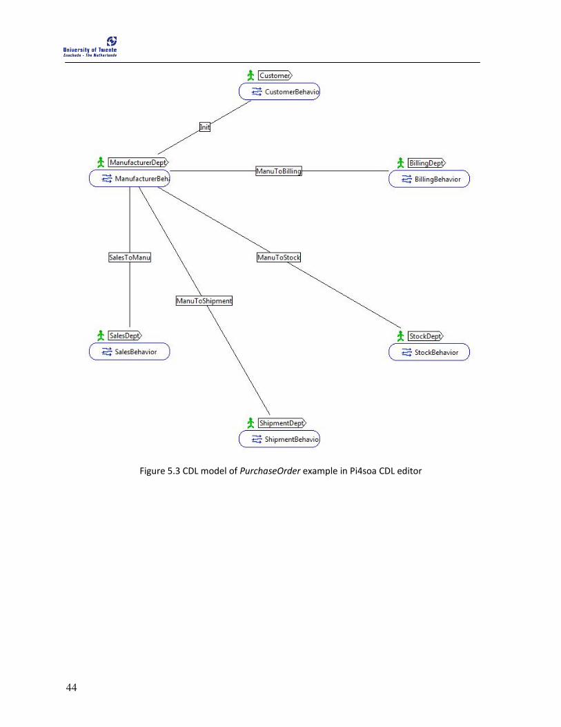
44
Figure 5.3 CDL model of PurchaseOrder example in Pi4soa CDL editor
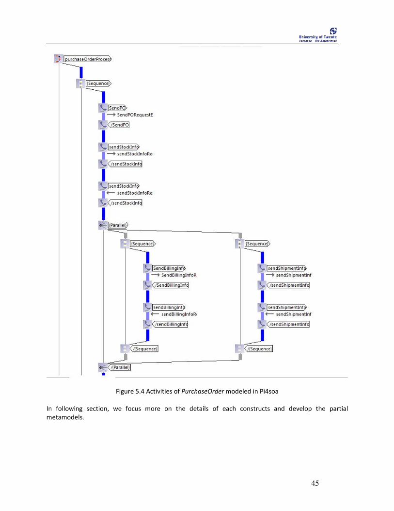
45
Figure 5.4 Activities of PurchaseOrder modeled in Pi4soa
In following section, we focus more on the details of each constructs and develop the partial
metamodels.

46
5.2 WS-CDL metamodel The basic language syntax of CDL is presented in Listing 5.1. We refer to the details of each language
construct in subsections that follow. We explain the language constructs using the example of
PurchaseOrder application scenario.
Listing 5.1 Basic language structure of WCDL (Kavantzas, Burdett et al. 2005)
<package name="NCName" author="xsd:string"? version="xsd:string"?
targetNamespace="uri" xmlns="http://www.w3.org/2005/10/cdl">
<informationType/>*
<token/>*
<tokenLocator/>*
<roleType/>*
<relationshipType/>*
<participantType/>*
<channelType/>*
<!-- Choreography-Notation* -- >
<choreography name="NCName" complete="xsd:boolean XPath-expression"?
isolation="true"|"false"? root="true"|"false"? coordination="true"|"false"? >
<relationship type="QName" />+
variableDefinitions?
Choreography-Notation*
Activity-Notation
<exceptionBlock name="NCName">
WorkUnit-Notation+
</exceptionBlock>?
<finalizerBlock name="NCName">
Activity-Notation
</finalizerBlock>*
</choreography>
</package>
Root Choreography Package The <package> element is the root of every choreography definition and is the container for all other
constructs. The package contains the following CDL type definitions: <informationType>, <token> and
<tokenLocator>, <roleType>, <relationshipType>, <participantType>, <channelType> and package-level
choreographies. The top level attributes namely: ‘name’, ‘author’, and ‘version’ specify the authoring
properties of the choreography documents. The namespace associated with all the definitions contained
in the choreography package is defined in ‘targetNamespace’ attribute. Listing 5.2 presents the package
code snippet of the purchaseOrder scenario.
Listing 5.2 Example of choreography package
<package xmlns=http://www.w3.org/2005/10/cdl
xmlns:cdl="http://www.w3.org/2005/10/cdl"

47
xmlns:cdl2="http://www.pi4soa.org/cdl2"
xmlns:tns="http://www.pi4soa.org/purchaseOrder"
xmlns:xsd="http://www.w3.org/2001/XMLSchema" author="Ravi" name="purchaseOrder"
targetNamespace="http://www.pi4soa.org/purchaseOrder" version="0.1">
.
.
.
</package>
The metamodel for the root choreography package is depicted in Figure 5.5.
Figure 5.5 Metamodel for root choreography package
We categorize the concepts of CDL into collaborating constructs, information-driven constructs, activity
constructs, and choreography construct. All these constructs are contained in root choreography
package. We explain each constructs in the following subsections.
48
5.2.1 Collaborating Constructs The message exchanged among the parties and their coupling is represented by the collaborating
constructs of WS-CDL which includes: <roleType>, <participantType>, <relationshipType>, and
<channelType>. In following sections we explain them briefly.
• roleType
A <roleType> construct represents the observable behavior of a particular participating service
(<participantType>). The operation implemented by a given participant with a specific role is specified
by <roleType> construct. For instance, in our example of purchaseOrder, every department has a specific
role with their respective behaviors as shown in the code snippet of Listing 5.3. The <behaviour> sub-
element specifies the observable behavior of a participant that can be used to interact with other
collaborating parties. A choreography package can have zero or more <roleType> constructs.
Listing 5.3 Example of <roleType> construct
<roleType name="BillingDept">
<behavior name="BillingBehavior" />
</roleType>
<roleType name="SalesDept">
<behavior name="SalesBehavior" />
</roleType>
<roleType name="ShipmentDept">
<behavior name="ShipmentBehavior" />
</roleType>
<roleType name="StockDept">
<behavior name="StockBehavior" />
</roleType>
• participantType
A <participantType> construct represents an entity playing a particular set of roles in the choreography
and logically groups the observable behaviors of the roles. For instance, in our example of purchase
order each department is represented as a participant grouping a particular set of roles. Listing 5.3
shows the part of the example with <participantType>. The <participantType>includes the roles using
the <roleType> construct. A choreography package can have zero or more <participantType>s.
Listing 5.4 Example of <participantType> construct
<participantType name="BillingDeptParticipant">
<roleType typeRef="tns:BillingDept"/>
</participantType>
<participantType name="SalesDeptParticipant">
<roleType typeRef="tns:SalesDept"/>
</participantType>
<participantType name="ShipmentDeptParticipant">
<roleType typeRef="tns:ShipmentDept"/>
</participantType>
<participantType name="StockDeptParticipant">
<roleType typeRef="tns:StockDept"/>

49
</participantType>
• relationshipType
A <relationshipType> concept is used to define the relation between the roles such that the
collaboration can be established using such relationships. A <relationshipType> concept expresses the
commitments of each participant with each other and expresses the relationship by combining the
existing <roleType>s and behaviors. For instance, in our example scenario, the selling department is
related with the stock department and is represented by SalesDeptToStockDeptRel relationship. Every
<relationshipType> exactly contains two roles to define 1-to-1 relation among the participants. The
portion of code shown in Listing 5.5 represents the <relationshipType>construct. A choreography
package can have zero or more <relationshipType>s.
Listing 5.5 Example of <relationshipType> construct
< relationshipType name="BillingDeptToSalesDeptRel">
<roleType typeRef="tns:BillingDept"/>
<roleType typeRef="tns:SalesDept"/>
</relationshipType>
<relationshipType name="SalesDeptToStockDeptRel">
<roleType typeRef="tns:SalesDept"/>
<roleType typeRef="tns:StockDept"/>
</relationshipType>
• channelType
To finalize the collaboration among the participants, the <channelType> construct is used as a point of
communication between the participating parties by specifying where and how the message is
exchanged. Further, the action attribute of <channelType> constructs is used to model the message
exchange pattern namely: request-response, response, and request (default). Listing 5.6 depicts the
<channelType>s that are used in the example scenario. It is also important to notice that channel
variables are used for correlation of messages. For instance, when the ordered good is found in the
stock then ID token is associated with it for correlation with the identity element. The primary value of
the type attribute indicates ID is created. Later, ID token is passed to ShipmentDeptChannelType of
ShipmentDept role. The associated type in ShipmentDeptChannelType indicates that the channel
instance identity is correlated with the ID token from of StockDeptChannelType.
Listing 5.6 Example of <channelType> construct
<channelType name="StockDeptChannelType">
<roleType typeRef="tns:StockDept"/>
<reference>
<token name="tns:URIToken"/>
</reference>
<identity type="primary">
<token name="tns:ID"/>
</identity>
</channelType>
<channelType name="ShipmentDeptChannelType">
<roleType typeRef="tns:ShipmentDept"/>
<reference>
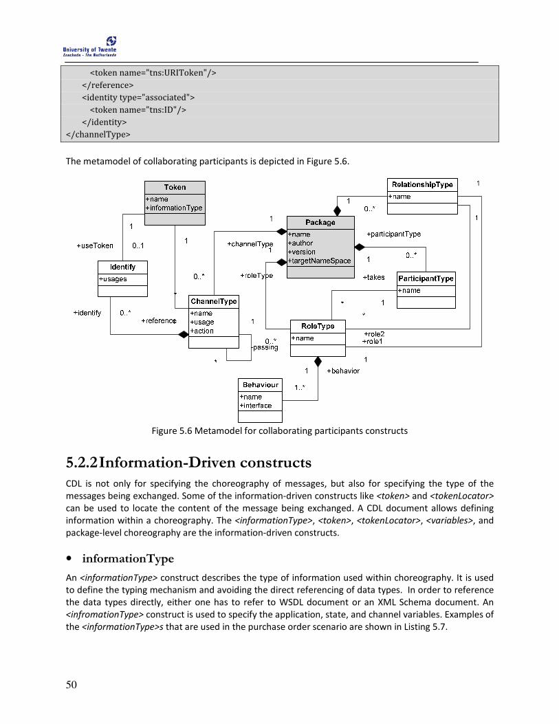
50
<token name="tns:URIToken"/>
</reference>
<identity type="associated">
<token name="tns:ID"/>
</identity>
</channelType>
The metamodel of collaborating participants is depicted in Figure 5.6.
Figure 5.6 Metamodel for collaborating participants constructs
5.2.2 Information-Driven constructs CDL is not only for specifying the choreography of messages, but also for specifying the type of the
messages being exchanged. Some of the information-driven constructs like <token> and <tokenLocator>
can be used to locate the content of the message being exchanged. A CDL document allows defining
information within a choreography. The <informationType>, <token>, <tokenLocator>, <variables>, and
package-level choreography are the information-driven constructs.
• informationType
An <informationType> construct describes the type of information used within choreography. It is used
to define the typing mechanism and avoiding the direct referencing of data types. In order to reference
the data types directly, either one has to refer to WSDL document or an XML Schema document. An
<infromationType> construct is used to specify the application, state, and channel variables. Examples of
the <informationType>s that are used in the purchase order scenario are shown in Listing 5.7.
51
Listing 5.7 Example of <informationType> construct
<informationType name="CheckStockRequest" element="CheckStockRequest" />
<informationType name="GoodRequest" element="GoodRequest" />
<informationType name="URITokenType" type="xsd:anyURI" />
<informationType name="IDType" type="xsd:string" />
• token and tokenLocators
A <token> is an alias of a variable in a choreography that defines the piece of data of the message being
exchanged. A <tokenLocator> construct provide a query mechanism to select such tokens using XPath
expressions. In Listing 5.8, we present some of the examples of tokens and <tokenLocator>s that are
used in the purchase order scenario. As shown in example, the ID token represents the data that is being
exchanged through IDType and <tokenLocator> is used to query over the <informationType> to select an
ID token.
Listing 5.8 Example of <token> and <tokenLocator>
<token name="ID" informationType="tns:IDType" />
<token name="URIToken" informationType="tns:URITokenType" />
<tokenLocator tokenName="tns:ID" informationType="tns:GoodRequest"
name="GoodRequestIDLocator" query="//@id"/ >
<tokenLocator tokenName="tns:ID" informationType="tns:POResponse"
name="POResponseIDLocator" query="//@id"/ >
• Variables
Variables capture information about objects in a choreography and they can be an information
exchange capturing variable, state capturing variables, channel capturing variables, or exception
capturing variables. A <variableDefinations> construct is used to define one or more variables within a
choreography. Listing 5.9 shows some of the <informationType> and <channelVariable> used in the
PurchaseOrder application scenario.
Listing 5.9 Example of variables
<variableDefinitions>
<variable informationType="tns:GoodRequest" name="good">
<variable channelType="tns:BillingDeptChannelType" name="BillingDeptChannel">
<variable channelType="tns:ShipmentDeptChannelType" name="ShipmentDeptChannel"/>
<variable channelType="tns:StockDeptChannelType" name="StockDeptChannel"/>
</variableDefinitions>
• WorkUnit
A <workunit> prescribes the constraints that have to be fulfilled for making progress and performing
work within a choreography. A <workunit> can also prescribe the constraints to preserve consistency of
the message exchange between the participating services. In a choreography, a <WorkUnit-Notation> is
used to define a <workunit>. The syntax of the <workunit> construct is shown in Listing 5.10.
Listing 5.10 Syntax of <workunit> construct
<workunit name="NCName"
guard="xsd:boolean XPath-expression"?
repeat="xsd:boolean XPath-expression"?
52
block="true|false"? >
Activity-Notation
</workunit>
The ‘name’ attribute specifies a unique name for workunit within a choreography package. The ‘guard’
condition of the workunit is specified in guard attribute. The ‘repeat’ attribute expresses the repetition
condition of a workunit. The ‘block’ attribute specifies whether the <workunit> has to block waiting for
referenced variables within the guard condition to become available. The <Activity-Notation> specifies
the enclosed activities within a <workunit> construct.
• Exception Handling
The exception handling constructs can be used to specify the alternative scenario in case of failures due
to exceptional circumstances within a choreography. The exceptional circumstances could be interaction
failures, timeout errors, validation errors, or application errors to name a few. Exception handling is
specified using the <exceptionBlock> construct and the syntax of <exceptionBlock>is shown in Listing
5.11.
Listing 5.11 Syntax of <exceptionBlock> construct
<exceptionBlock name=”NCName”>
WorkUnit-Notation+
</exceptionBlock>
The ‘name’ attribute is used to specify a unique name to a <exceptionBlock> construct. One or more
workunits can be defined within the <exceptionBlock>.
• Finalization
After the successful completion of an instance of choreography, finalization is used to express the effect
of choreography. The effect can be the modifications like confirm, cancel or otherwise modify the
effects of its completed actions of the choreography instance. Such modifications may be defined within
one or more <finalizerBlock> for an enclosed choreography. The syntax of <finalizerBlock>is shown in
Listing 5.12.
Listing 5.12 Syntax of <finalizerBlock> construct
<finalizerBlock name=”NCName”>
WorkUnit-Notation+
</finalizerBlock>
• Choreography
The core of a collaboration among the parties is defined by the <choreography> construct, which
specifies rules that govern the ordering of message exchange. The root choreography package encloses
one or more choreographies which can be defined locally and globally. The <choreography> construct
contains <relationship> construct which specifies the relationships that the current instance of
choreography may participate in. The <variableDefinations> constructs within choreography holds the
variables. The choreography also contains the activities defined within <Activity-Notions> construct and
optional <exceptionBlock> and <finalizerBlock> constructs for exception and compensation handling
respectively.

53
We illustrate the choreography concept using the example of the PurchaseOrder scenario in Listing 5.13.
This example is not complete and we present this example to explain some of the constructs used within
the choreography. The clear picture of the constructs contained within the choreography is presented in
Figure 5.1. The purchaseOrderProcess choreography has a relationship with BillingDeptToSalesDept and
also contains variables within <variableDefinations>. Two types of variable are presented here:
information exchange capturing variable named goods of GoodRequest type, and channel capturing
variable named ShipmentDeptChannel of ShipDeptChannelType. As per the requirements of the
choreography specification, a <sequence> activity that includes an <interaction> and <choice> activities
is also shown in the example.
Listing 5.13 Syntax of <choreography-Notation>
<choreography name="purchaseOrderProcess" root="true">
<relationship type="tns:BillingDeptToSalesDeptRel"/>
<variableDefinitions>
<variable informationType="tns:GoodRequest" name="goods"/>
<variable channelType="tns:ShipmentDeptChannelType" name="ShipmentDeptChannel"/>
</variableDefinitions>
<sequence>
<interaction channelVariable="tns:StockDeptChannel" name="GoodRequest"
operation="orderGood">
<participate fromRoleTypeRef="tns:SalesDept" relationshipType="tns:SalesDeptToStockDeptRel"
toRoleTypeRef="tns:StockDept"/>
<exchange action="request" informationType="tns:GoodRequest"
name="GoodRequestRequestExchange">
<send/>
<receive/>
</exchange>
</interaction>
<choice>
<description type="documentation">
Is Stock Valid?
</description>
</choice>
</sequence>
</choreography>
The metamodel of the information-driven constructs is shown in Figure 5.7.

54
Figure 5.7 Metamodel of the Information Driven collaboration
5.2.3 Activities The <Activity-Notation> construct is used to define activities within a choreography which basically
describe the actions to be performed. We explain various activities within a choreography in the
following sections.
• Ordering structures
Ordering structures combine activities with other ordering structures in a nested way to express the
ordering rules of actions performed within a choreography. The ordering structures contain one or more
<Activity-Notation>s. <sequence>, <parallel>, and <choice> are the ordering structures that can be found
within a choreography. The <sequence> construct is used to specify the ordering of the enclosed
activities in the same order that they are defined. The <parallel> construct is used to represent the
ordering of the enclosed activities concurrently. The <choice> construct is used to specify that only one
of two or more activities should be performed.
Listing 5.14 presents the <sequence> and <choice> activities that are used in the example of
PurchaseOrder application scenario. In this example, the <sequence> activity is used to define the
ordering of <interaction> activity named GoodRequest between SalesDept role and StockDept role. The
<interaction> activity is then followed by the <choice> activity to check the stock of the ordered good.
The <choice> is then followed by two sequences namely: stockCheckOk and stockInvalid, which we did
not model to limit the complexity of the process because it calls the production department for the
production of the specified good. The choreography process continues with the respective activities for
shipment department (shipInfoRequest) and the billing department. We have underlined and bold-faced
the above mentioned activities in the example code for better readability.

55
Listing 5.14 Example of <sequence> and <choice> constructs
<sequence>
<interaction channelVariable="tns:StockDeptChannel" name="GoodRequest"
operation="orderGood">
<participate fromRoleTypeRef="tns:SalesDept"
relationshipType="tns:SalesDeptToStockDeptRel" toRoleTypeRef="tns:StockDept"/>
<exchange action="request" informationType="tns:GoodRequest"
name="GoodRequestRequestExchange">
<send/>
<receive/>
</exchange>
</interaction>
<choice>
<description type="documentation">
Is Stock Valid?
</description>
<sequence>
<interaction channelVariable="tns:StockDeptChannel" name="StockCheckOk"
operation="orderGood">
………
……….
</interaction>
<interaction channelVariable="tns:StockDeptChannel1" name="ShipInfoRequest"
operation="sendStockMsg">
…………
……………
</interaction>
</sequence>
</choice>
…………
</sequence>
• Interacting activity
An <interaction> construct describes an exchange of information between the various services. An
interaction is initiated when one of the <roleType>s participating in the interaction sends a message
through a common channel to another <roleType> that is participating in the interaction. For instance, in
our example shown in Listing 5.15, when the SalesDept sends GoodRequest to StockDept through
StockDeptChannel, then the <interaction> activity is used.
Listing 5.15 Example of <interaction> construct
<interaction channelVariable="tns:StockDeptChannel" name="GoodRequest" operation="orderGood">
<participate fromRoleTypeRef="tns:SalesDept"
relationshipType="tns:SalesDeptToStockDeptRel" toRoleTypeRef="tns:StockDept"/>
<exchange action="request" informationType="tns:GoodRequest"
name="GoodRequestRequestExchange">
<send/>
<receive/>

56
</exchange>
</interaction>
The <send> and <receive> elements within <exchange> construct specify the variables being sent and
received respectively.
• Composition activity
The composition of choreographies can be realized using the <perform> construct which combines
existing choreographies to create new ones. The syntax of the <perform> construct is shown in Listing
5.16.
Listing 5.16 Syntax of <perform> construct
<perform choreographyName="QName"
choreographyInstanceId="XPath-expression"?
block="true|false"? >
<bind name="NCName">
<this variable="XPath-expression" roleType="QName"/>
<free variable="XPath-expression" roleType="QName"/>
</bind>*
Choreography-Notation?
</perform>
The ‘choreographyName’ attribute references the name of the choreography to be performed and the
‘choreographyInstanceId‘ defines the identifier. The <bind> construct within <perform> construct
enables the information in the performing choreography to be shared with the performed choreography
and vice-versa.
• Silent and absence of actions
The <silentAction> construct is used for marking the point where participant-specific actions with non-
observable operation details need to be performed. The absence of actions is specified using <noAction>
construct, which is used for marking the point where a participant does not perform any action. The
syntax of <silentAction> and <noAction> constructs is shown in Listing 5.17.
Listing 5.17 Syntax of <silentAction> and <noAction> constructs
<silentAction roleType="QName"? />
<noAction roleType="QName? />
Each construct has a <roleType> which specifies the role played by the participant that performs the
action.
• Assigning Variables
The <assign> construct is used to create or change, and then make available, the value of one or more
variables using the value of another variable or expression. The syntax of the <assign>construct is shown
in 5.18.
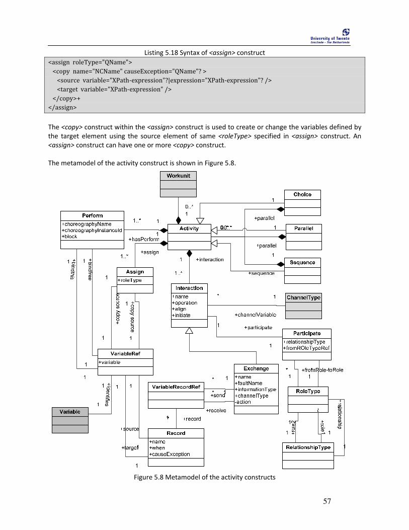
57
Listing 5.18 Syntax of <assign> construct
<assign roleType="QName">
<copy name="NCName" causeException="QName"? >
<source variable="XPath-expression"?|expression="XPath-expression"? />
<target variable="XPath-expression" />
</copy>+
</assign>
The <copy> construct within the <assign> construct is used to create or change the variables defined by
the target element using the source element of same <roleType> specified in <assign> construct. An
<assign> construct can have one or more <copy> construct.
The metamodel of the activity construct is shown in Figure 5.8.
Figure 5.8 Metamodel of the activity constructs

58
The combined metamodel of the above presented CDL constructs is presented in Figure 5.9.
Syntactically, the metamodel is not complete. Initially, we generated the metamodel automatically using
the schema of CDL as explained in the article7. The generated metamodel turned out to be very complex
and generated all the constructs from XSD such that it was difficult to explain all of the constructs.
Hence, we developed the metamodel manually and modeled it in Eclipse Modeling Framework8 (EMF)
using the CDL language specification.
7 http://www.eclipse.org/modeling/emf/docs/2.x/tutorials/xlibmod/xlibmod_emf2.0.html
8 http://www.eclipse.org/modeling/emf/
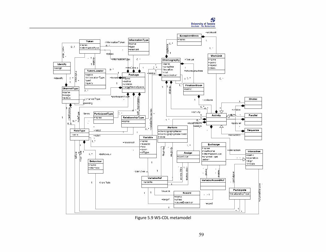
59
Figure 5.9 WS-CDL metamodel

60

61
6 Modeling Service Orchestration
his chapter presents metamodel for WS-BPEL 2.0 (Alves, Arkin et al. 2007). The metamodel represents the syntactically valid specification of WS-BPEL and is the target
metamodel for the transformation. Since WS-BPEL specification is complex, we split the description of the language constructs and the metamodel into several sections. Later, we provide a complete metamodel at the end. We illustrate the concepts and constructs of BPEL using an example from the application scenario presented in Chapter 4. We do not intend to present the overall syntax for the constructs unless it is necessary. We refer the readers to WS-BPEL 2.0 (Alves, Arkin et al. 2007) for the syntactical details of the language specification.
This chapter is structured as follows: Section 6.1 presents the brief overview of BPEL with an example. Section 6.2 and its subsections describe the language constructs of BPEL in detail along with the partial metamodels which we later combine as one.
6.1 Introduction BPEL is an imperative, XML-based language to describe the behavior of a business process based on
interactions between the process and its collaborating parties. A BPEL process defines how multiple
service interactions with parties are coordinated to achieve a business goal. Each collaborating parties
interacting with a BPEL process is defined using a <partnerLink>. A BPEL process describes the execution
order of its collaborating parties via basic and structured activities. Basic activities mainly define
message exchange between the parties. For instance, <invoke> activity is used to invoke a partner
service, <receive> to receive a Web service invocation in a synchronized scenario. The <reply> activity is
used to send a response message to a previously received Web service invocation message. Additionally,
structured activities are similar to control flow constructs in imperative programming languages and
represents the order in which a collection of activities in executed. For instance, a <sequence> activity is
used to execute a given set of activities within a sequence; <flow> to achieve parallelism; <while>,
<ForEach>, and <RepaeatUntil> to represent loops, and <if-else> to represent conditional branching.
In Figure 6.1, we illustrate the diagrammatic representation of manufacturing process of PurchaseOrder
application scenario to give a brief overview of BPEL. The manufacturing process interacts with stock,
shipment, billing, and sales department which are modeled as <partnerLink> in the process. Each
department may act as an atomic service or a process and for simplicity we assume them to be an
atomic service. The message exchange among various departments is carried out with one of the
following basic activities: <receive>, <invoke>, or <reply>. Each of these structured activities interacts
through a variable. For instance, the sales service interacts with the manufacturing process through V1
variable and process uses <assign> construct to extract POID and copy it to GoodInStock variable using
<copy> construct. <assign> is a structured activity that is used to copy the value of variable to another
variable. The manufacturing process also calls shipment service and billing service. Those two
invocations can be executed concurrently in BPEL using <flow> activity and we illustrate it using the fork
in the figure. Both of the calls wait for the callback response from each service. The process ends when
the process sends the purchaseOrderResponse to the sales service.
T

62
Figure 6.1 Activity diagram of the Manufacturing process of the purchaseOrder scenario
Figure 5.1 is just an example of a process in BPEL which can express the orchestration process by
composing the other partner services. Apart from the above mentioned constructs, BPEL is enriched
with constructs to maintain the stateful message exchanges, error and fault handling, and compensation
handling.
With this brief overview of BPEL and the diagrammatic illustrations, we believe that BPEL can specify the
requirements of an orchestration that we explored in Section 2.1.2. In fact, BPEL is the de-facto standard
for specifying orchestration and there already exists large number of orchestration engines that can
execute BPEL processes like ActiveBPEL9, BizTalk Server
10, Oracle BPEL Process Manager
11, OpenESB
12,
jBPM13
, webSphere process server14
. The wide acceptance in industry and de-facto standard are the
reasons that motivated us to choose BPEL as the orchestration language in this research.
9 http://www.activevos.com/community-open-source.php
10 http://www.microsoft.com/biztalk/en/us/default.aspx
11 http://www.oracle.com/technetwork/middleware/bpel/overview/index.html
12 https://open-esb.dev.java.net/
13 http://www.jboss.org/jbpm/
14 http://www-01.ibm.com/software/integration/wps/

63
6.2 WS-BPEL metamodel The language syntax of BPEL is presented in Listing 6.1. We refer to the details of each language
constructs in respective subsections.
Listing 6.1: Language syntax of BPEL
<process name="NCName" targetNamespace="anyURI"
queryLanguage="anyURI"?
expressionLanguage ="anyURI"?
suppressJoinFailure="yes|no"?
exitOnStandardFault="yes|no"?
xmlns="http://docs.oasis-open.org/wsbpel/2.0/process/executable">
<extensions>?
<extension namespace="anyURI" mustUnderstand="yes|no" />+
</extensions>
<import namespace="anyURI"?
location="anyURI"?
importType="anyURI" />*
<partnerLinks>?
<partnerLink name="NCName"
partnerLinkType="QName"
myRole="NCName"?
partnerRole="NCName"?
initializePartnerRole="yes|no"?>+
</partnerLink>
</partnerLinks>
<messageExchanges>?
<messageExchange name="NCName" />+
</messageExchanges>
<variables>?
<variable name="BPELVariableName"
messageType="QName"?
type="QName"?
element="QName"?>+
from-spec?
</variable>
</variables>
<correlationSets>?
<correlationSet name="NCName" properties="QName-list" />+
</correlationSets>
64
<faultHandlers>?
<!-- faulthandler elements -->
</faultHandlers>
<eventHandlers>?
<!--Eventhandler elements -->
</eventHandlers>
Activity
</process>
6.2.1 Process Definition The language constructs of BPEL are contained within a <process> construct that has a unique name and
represents an executable process. The <process> construct describes the behavior of a business process
based on interactions between the process itself and its participating parties. The constructs that are
grouped within the process definition are shown in Listing 6.1 as basic the language syntax of BPEL and
the respective metamodel is shown in Figure 6.2.
In order to explain the constructs of the BPEL process, we group them into 6 categories namely: 1.
Linking Partners, 2. process variables and dataflow, 3. basic activities, 4. structured activities, and 5.
event, fault, and compensation handling. We explain each of these constructs and develop metamodel
for each in following sections.

65
Figure 6.2 Metamodel of WS-BPEL process definition
6.2.2 Linking Partners A BPEL process use <partnerLinks> to model conversational relationships with its partners. The
relationship is established by specifying the roles of each party and the interfaces that each provides. A
<partnerLink> specifies roles played by participating services or process in a collaboration. A role
specified in the attribute <myRole> indicates the role of the BPEL process being defined, while the
attribute <partnerRole> indicates the role of the partner. For instance, we present a code fragment of
centralized orchestration of PurchaseOrder application scenario in Listing 6.2 which will help to clarify
the relationships between the partners.
Listing 6.2 Example of <process> and <partnerLink> constructs
<process xmlns:bpws="http://schemas.xmlsoap.org/ws/2003/03/business-process/"
xmlns:xsd="http://www.w3.org/2001/XMLSchema"
xmlns:tns="http://example.org/purchaseOrder"
targetNamespace="http://example.org/purchaseOrder" name="purchaseOrder">
<partnerLinks>
<partnerLink name="ManufacturingDept" myRole=" ManufacturingDeptRole"
partnerLinkType="tns: ManufacturingDeptLT"/>
<partnerLink name="StockDept" partnerRole="StockDeptRole"
partnerLinkType="tns:StockDeptLT"/>

66
<partnerLink name="ShipmentDept" partnerLinkType="tns:ShipmentDeptLT"
partnerRole="ShipmentDeptRole"/>
<partnerLink name="BillingDept" partnerLinkType="tns:BillingDeptLT"
PartnerRole="BillingDeptRole"/>
</partnerLinks>
………….
</process>
In the BPEL process, all the 4 departments are represented as the <partnerLink> with their respective
names, and their roles. In the orchestration example, the manufacturing department acts as the
orchestrator and its relationship with the other departments is shown by the <partnerLink>s constructs.
The ‘myrole’ = ManufacturingDeptRole specifies that the manufacturing department as the BPEL process
and respective partnerRoles of other <partnerLink> represent the role of the partner.
6.2.3 Process variables and data flow Variables provide the means for holding application data or message that represents the state of a BPEL
process. Variables are also used to hold the data that are needed to maintain the stateful behavior or
the process. A variable within a scope in BPEL process must have unique. A variable is associated with
either an element defined in a schema, a type of XML Schema’s simple type, or a message defined in a
WSDL document. Using <assign> and <copy> message data can be copied and manipulated between
variables. We present the code fragment from the example scenario to illustrate the concepts of
<variable>, <assign>, and <copy> construct in Listing 6.3.
Listing 6.3 Example of the process variables and data flow
<variables>
<variable name="PurchaseOrder" messageType="tns:PurchaseOrder"/>
<variable name="PurchaseOrderResponse" messageType="tns:PurchaseOrderResponse"/>
<variable name="POID" type="xsd:string">
<variable name="GoodInStock" type="xsd:string"/>
</variables>
<assign>
<copy>
<from variable="POID" part="PurchaseOrder"/>
<to variable="GoodInStock" part="PurchaseOrder"/>
</copy>
</assign>
In the above example, variables are declared inside the <variables> constructs and the data flow is
represented using <assign> and <copy> construct where the POID is copied to GoodInStock for further
processing in Stock service.
6.2.4 Basic Activities Basic activities are used to define communication primitives for interacting with the partners and have
predefined functions. Basic activities are used to define communication primitives for interacting with
the partners and have predefined functions. For instance, <invoke> construct is used to invoke a partner
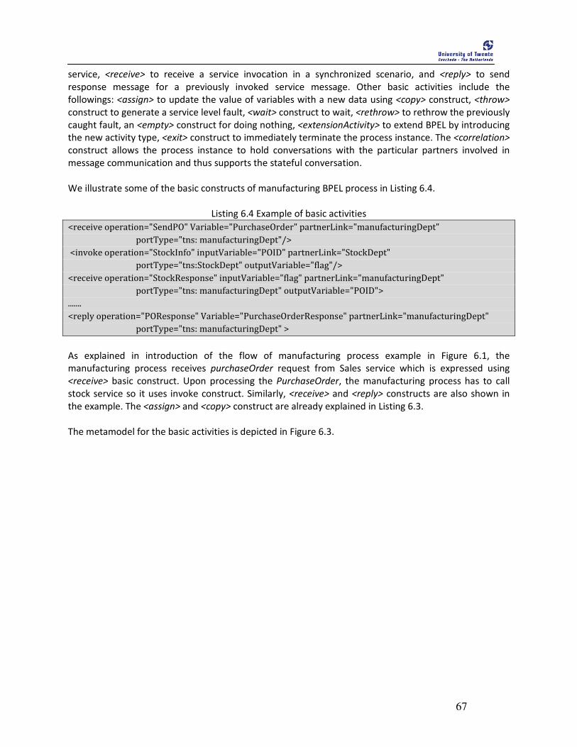
67
service, <receive> to receive a service invocation in a synchronized scenario, and <reply> to send
response message for a previously invoked service message. Other basic activities include the
followings: <assign> to update the value of variables with a new data using <copy> construct, <throw>
construct to generate a service level fault, <wait> construct to wait, <rethrow> to rethrow the previously
caught fault, an <empty> construct for doing nothing, <extensionActivity> to extend BPEL by introducing
the new activity type, <exit> construct to immediately terminate the process instance. The <correlation>
construct allows the process instance to hold conversations with the particular partners involved in
message communication and thus supports the stateful conversation.
We illustrate some of the basic constructs of manufacturing BPEL process in Listing 6.4.
Listing 6.4 Example of basic activities
<receive operation="SendPO" Variable="PurchaseOrder" partnerLink="manufacturingDept"
portType="tns: manufacturingDept"/>
<invoke operation="StockInfo" inputVariable="POID" partnerLink="StockDept"
portType="tns:StockDept" outputVariable="flag"/>
<receive operation="StockResponse" inputVariable="flag" partnerLink="manufacturingDept"
portType="tns: manufacturingDept" outputVariable="POID">
.......
<reply operation="POResponse" Variable="PurchaseOrderResponse" partnerLink="manufacturingDept"
portType="tns: manufacturingDept" >
As explained in introduction of the flow of manufacturing process example in Figure 6.1, the
manufacturing process receives purchaseOrder request from Sales service which is expressed using
<receive> basic construct. Upon processing the PurchaseOrder, the manufacturing process has to call
stock service so it uses invoke construct. Similarly, <receive> and <reply> constructs are also shown in
the example. The <assign> and <copy> construct are already explained in Listing 6.3.
The metamodel for the basic activities is depicted in Figure 6.3.

68
Figure 6.3 Metamodel of basic activities of BPEL
6.2.5 Structured Activities The structured activities represent the order in which a collection of activities are executed and
functionally resembles to the control-flow constructs in imperative programming languages. The
structured activities in BPEL include the following: <sequence> construct to execute a set of activities in
a predefined order, <flow> construct to support the parallel execution, <if-else> construct to support a
conditional execution based on and consists of <elseif> and <else> blocks, <while> construct to perform
one or more activities repeatedly until the condition holds true, <repeatUntil> to execute activity at least
once, <pick> to block the process and to wait until one of the specified events occurs, and <scope>
construct to provide a shared context for variables and the handlers.
In Listing 6.5 we present the use of some of the structured constructs in the PurchaseOrder scenario
consisting of <sequence>, <flow> and activities inside the <sequence> and <flow> constructs.
Listing 6.5 code sample of structured activities
<sequence>
<flow>
<sequence>
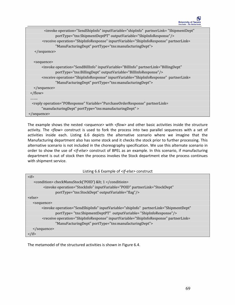
69
<invoke operation="SendShipInfo" inputVariable="shipInfo" partnerLink= "ShipmentDept"
portType="tns:ShipmentDeptPT" outputVariable="ShipInfoResponse"/>
<receive operation="ShipInfoResponse" inpurtVariable="ShipInfoResponse" partnerLink=
"ManuFacturingDept" portType="tns:manufacturingDept">
</sequence>
<sequence>
<invoke operation="SendBillInfo" inputVariable="BillInfo" partnerLink="BillingDept"
portType="tns:BillingDept" outputVariable="BillInfoResponse"/>
<receive operation="ShipInfoResponse" inpurtVariable="ShipInfoResponse" partnerLink=
"ManuFacturingDept" portType="tns:manufacturingDept">
</sequence>
</flow>
……..
<reply operation="POResponse" Variable="PurchaseOrderResponse" partnerLink=
"manufacturingDept" portType="tns:manufacturingDept" >
</sequence>
The example shows the nested <sequence> with <flow> and other basic activities inside the structure
activity. The <flow> construct is used to fork the process into two parallel sequences with a set of
activities inside each. Listing 6.6 depicts the alternative scenario where we imagine that the
Manufacturing department also has some stock and it checks the stock prior to further processing. This
alternative scenario is not included in the choreography specification. We use this alternate scenario in
order to show the use of <if-else> construct of BPEL as an example. In this scenario, if manufacturing
department is out of stock then the process invokes the Stock department else the process continues
with shipment service.
Listing 6.6 Example of <if-else> construct
<if>
<condition> checkManuStock(‘POID’) < 1 </conditioin>
<invoke operation="StockInfo" inputVariable="POID" partnerLink="StockDept"
portType="tns:StockDept" outputVariable="flag"/>
<else>
<sequence>
<invoke operation="SendShipInfo" inputVariable="shipInfo" partnerLink="ShipmentDept"
portType= "tns:ShipmentDeptPT" outputVariable= "ShipInfoResponse"/>
<receive operation="ShipInfoResponse" inpurtVariable="ShipInfoResponse" partnerLink=
"ManuFacturingDept" portType="tns:manufacturingDept">
</sequence>
</if>
The metamodel of the structured activities is shown in Figure 6.4.
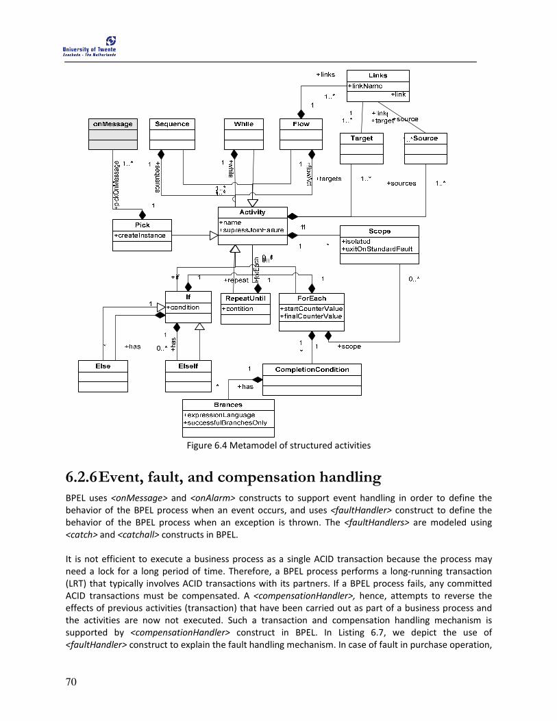
70
Figure 6.4 Metamodel of structured activities
6.2.6 Event, fault, and compensation handling BPEL uses <onMessage> and <onAlarm> constructs to support event handling in order to define the
behavior of the BPEL process when an event occurs, and uses <faultHandler> construct to define the
behavior of the BPEL process when an exception is thrown. The <faultHandlers> are modeled using
<catch> and <catchall> constructs in BPEL.
It is not efficient to execute a business process as a single ACID transaction because the process may
need a lock for a long period of time. Therefore, a BPEL process performs a long-running transaction
(LRT) that typically involves ACID transactions with its partners. If a BPEL process fails, any committed
ACID transactions must be compensated. A <compensationHandler>, hence, attempts to reverse the
effects of previous activities (transaction) that have been carried out as part of a business process and
the activities are now not executed. Such a transaction and compensation handling mechanism is
supported by <compensationHandler> construct in BPEL. In Listing 6.7, we depict the use of
<faultHandler> construct to explain the fault handling mechanism. In case of fault in purchase operation,
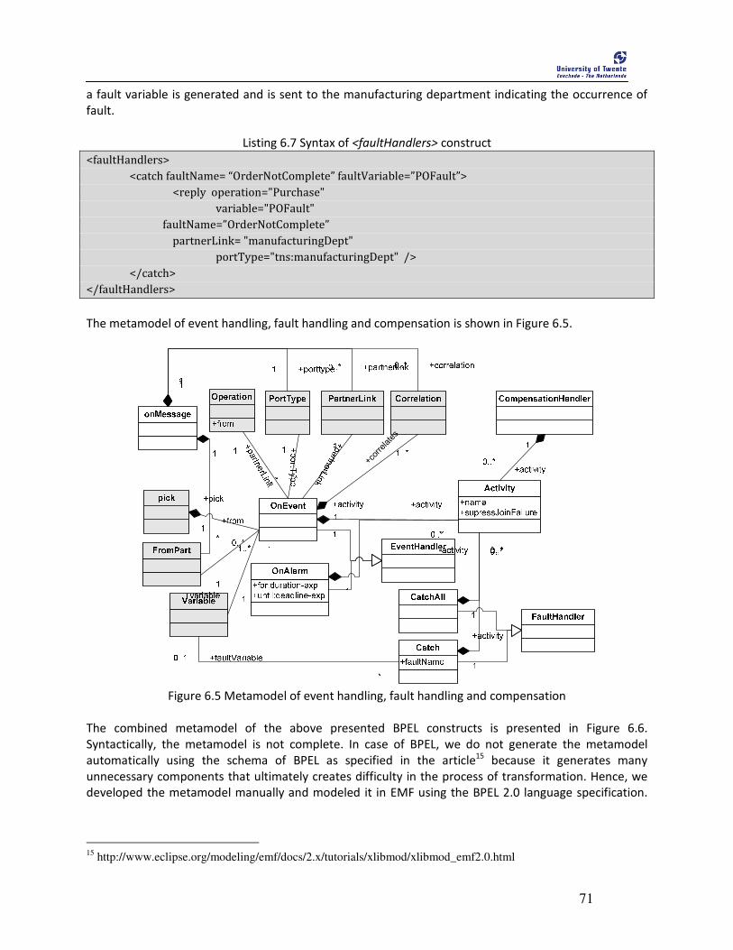
71
a fault variable is generated and is sent to the manufacturing department indicating the occurrence of
fault.
Listing 6.7 Syntax of <faultHandlers> construct
<faultHandlers>
<catch faultName= “OrderNotComplete” faultVariable=”POFault”>
<reply operation="Purchase"
variable="POFault"
faultName=”OrderNotComplete”
partnerLink= "manufacturingDept"
portType="tns:manufacturingDept" />
</catch>
</faultHandlers>
The metamodel of event handling, fault handling and compensation is shown in Figure 6.5.
+correlates
Figure 6.5 Metamodel of event handling, fault handling and compensation
The combined metamodel of the above presented BPEL constructs is presented in Figure 6.6.
Syntactically, the metamodel is not complete. In case of BPEL, we do not generate the metamodel
automatically using the schema of BPEL as specified in the article15
because it generates many
unnecessary components that ultimately creates difficulty in the process of transformation. Hence, we
developed the metamodel manually and modeled it in EMF using the BPEL 2.0 language specification.
15
http://www.eclipse.org/modeling/emf/docs/2.x/tutorials/xlibmod/xlibmod_emf2.0.html
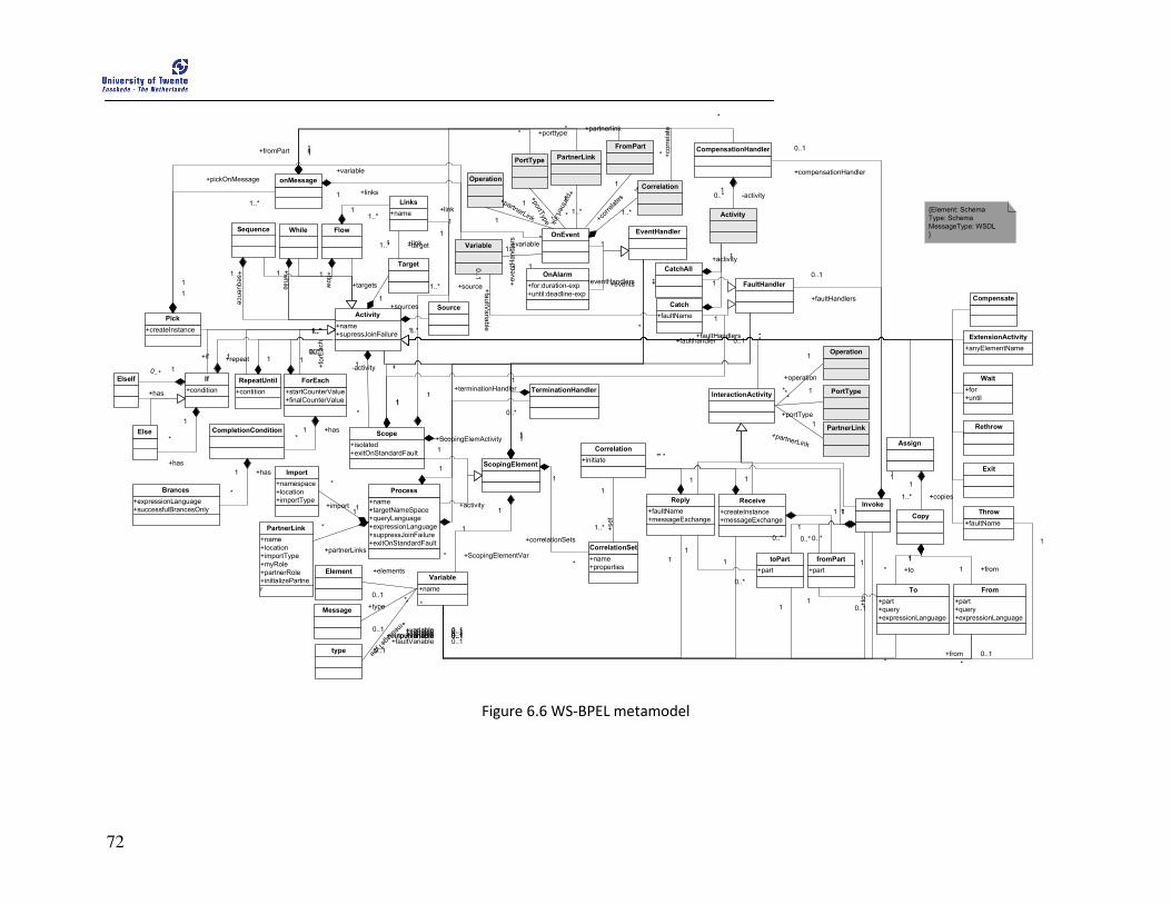
72
+name
+targetNameSpace
+queryLanguage
+expressionLanguage
+suppressJoinFailure
+exitOnStandardFault
Process+namespace
+location
+importType
Import
+name
+location
+importType
+myRole
+partnerRole
+initializePartne
r
PartnerLink
ScopingElement
1
+partnerLinks
*
1
+faultHandlers *
1
+eventHandlers *
+ScopingElemActivity 1
*
+name
Variable
1
+ScopingElementVar*
1
+correlationSets
*Element +elements
0..1*
Message
type
+type
0..1
*
+messageType0..1
*
1+import
*
+name
+supressJoinFailure
Activity
Invoke
+for
+until
Wait
+anyElementName
ExtensionActivity
1
+targets1..*
Target
Source
1
+sources
1..*
InteractionActivity
+partnerLink
1
*
+portType
1*
+operation
1
*
1
-inputvariable 0..1
1
+outputvariable 0..1
+initiate
Correlation
1
+compensationHandler
0..1
1
+faultHandlers
0..1
+createInstance
+messageExchange
Receive
1
+variable 0..1
+faultName
+messageExchange
Reply
1
+variable 0..1
+part
toPart
+part
fromPart
1 +to
0..11
+from 0..1
1
0..*
1
0..*
1
0..*
1
0..*
+name
+properties
CorrelationSet
1
+set
1..*
Assign
Copy
1
+copies1..*
+part
+query
+expressionLanguage
To
+part
+query
+expressionLanguage
From
1
+to*
1
+from1
*
+variable 0..1
*
+variable 0..1
Rethrow
+faultName
Throw
Exit
1
+faultVariable 0..1
1
*
1
*
1
*
+contition
RepeatUntil
+startCounterValue
+finalCounterValue
ForEach
+condition
If
CompletionCondition
+expressionLanguage
+successfulBrancesOnly
Brances
+has1*
+has1
*
+link1 +target1..*
1
+has
0..*
+if 10..*
+isolated
+exitOnStandardFault
Scope
1
*
+repeat 10..*
1
+forEach
0..*
WhileSequence Flow
+name
Links
+sequence
1
1..*
+while
1
1..*
+fl ow
1
1..*+createInstance
Pick
1 +eventHandlers
1..*
PartnerLink
PortType
Operation
ElseIf
OnEvent
PartnerLink
Operation
PortType
+partnerLink1
*
+portType
1
*
+partnerLink
1
*
FromPart
+for:duration-exp
+until:deadline-exp
OnAlarm
-fromPart1
1..*
Variable +variable
1 1
Activity
EventHandler
CompensationHandler
1-activity0..*
Correlation
1
+cor
relate
s
1..*
FaultHandler
+faultName
Catch
CatchAll
+faultV
ariable
0..1
*
{Element: Schema
Type: Schema
MessageType: WSDL
}
+link
1
+source1..*
1
+links
1..*
+activity
1
*
1
*
onMessage
1
+pickOnMessage
1..*
+variable
1
1
+fromPart 1
Else
1
+has
*
1
+faulthandler 0..1
1
+events *
1
*
+activity
1
*
1
*
1
+terminationHandler
0..*
TerminationHandler
1
-activity *
Compensate
1
+partnerlink*
1
+correlate
*1
+porttype*
Figure 6.6 WS-BPEL metamodel

75
7 CDL-to-BPEL Transformation
his chapter presents the transformation mappings of our CDL-to-BPEL transformation. We formalize the transformation mappings in order to avoid unambiguous
interpretation. We implement the transformation mappings as transformation rules in ATL as a proof-of-concept. We also explain the implementation approach that we have adopted in order to realize the CDL-to-BPEL mapping.
This chapter is structured as follows: Section 7.1 presents the transformation chain of implementation procedure. Section 7.2 presents the CDL-to-BPEL transformation mapping. Section 7.3 explains the overall implementation procedure for CDL-to-BPEL focusing on the various transformations present in the transformation chain. Finally, Section 7.4 presents the limitation of our approach.
7.1 Transformation chain In this section, we explain our transformation procedure that we used in our approach to achieve the
CDL-to-BPEL transformation. The metamodel transformation approach that we adopted in our approach
is depicted in Figure 7.1. Based on the transformation specification presented in Section 4.3.1 for
centralized orchestration, we develop transformation mapping from CDL to BPEL language elements.
This mapping is then implemented as transformation rules in ATL transformation language.
Figure 7.1 CDL-to-BPEL metamodel transformation approach
The transformation approach presented in Figure 7.1 takes CDL model and runs the transformation rules
in ATL engine to generate the BPEL model. However, to execute the ATL transformation rules, an ATL
T
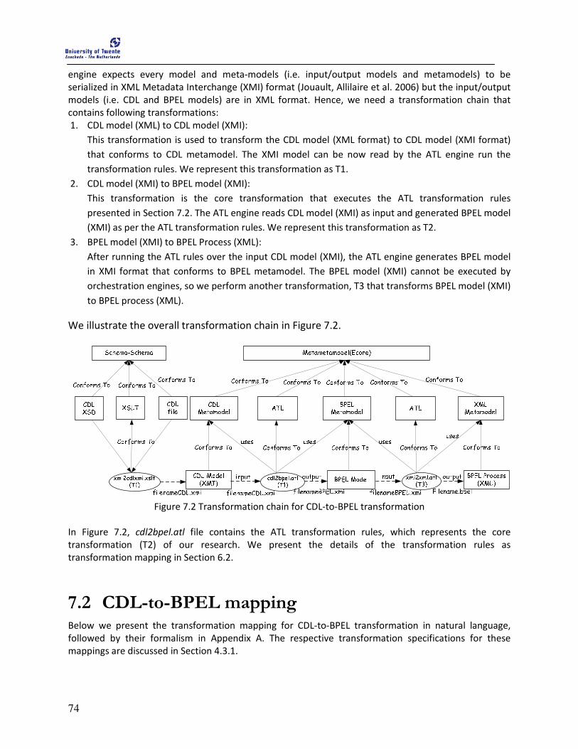
74
engine expects every model and meta-models (i.e. input/output models and metamodels) to be
serialized in XML Metadata Interchange (XMI) format (Jouault, Allilaire et al. 2006) but the input/output
models (i.e. CDL and BPEL models) are in XML format. Hence, we need a transformation chain that
contains following transformations:
1. CDL model (XML) to CDL model (XMI):
This transformation is used to transform the CDL model (XML format) to CDL model (XMI format)
that conforms to CDL metamodel. The XMI model can be now read by the ATL engine run the
transformation rules. We represent this transformation as T1.
2. CDL model (XMI) to BPEL model (XMI):
This transformation is the core transformation that executes the ATL transformation rules
presented in Section 7.2. The ATL engine reads CDL model (XMI) as input and generated BPEL model
(XMI) as per the ATL transformation rules. We represent this transformation as T2.
3. BPEL model (XMI) to BPEL Process (XML):
After running the ATL rules over the input CDL model (XMI), the ATL engine generates BPEL model
in XMI format that conforms to BPEL metamodel. The BPEL model (XMI) cannot be executed by
orchestration engines, so we perform another transformation, T3 that transforms BPEL model (XMI)
to BPEL process (XML).
We illustrate the overall transformation chain in Figure 7.2.
Figure 7.2 Transformation chain for CDL-to-BPEL transformation
In Figure 7.2, cdl2bpel.atl file contains the ATL transformation rules, which represents the core
transformation (T2) of our research. We present the details of the transformation rules as
transformation mapping in Section 6.2.
7.2 CDL-to-BPEL mapping Below we present the transformation mapping for CDL-to-BPEL transformation in natural language,
followed by their formalism in Appendix A. The respective transformation specifications for these
mappings are discussed in Section 4.3.1.

75
The CDL-to-BPEL transformation mappings are implemented as a transformation rule in ATL language. A
transformation rule defines how a language concept in CDL is mapped into a relevant language concept
in BPEL. In both, CDL and BPEL metamodels, there are number of concepts with same name. In order to
avoid the naming confusion, we use cdl: and bpel: prefixes to indicate to which metamodels the
concepts belong. We categorize the mapping into two types:
• Structural mapping
A structural mapping represents the mapping of the concepts that are responsible for
establishing the collaboration and the message exchanges between the parties.
• Behavioral mapping
A behavioral mapping represents the mapping of the concepts that are responsible for
performing various activities between the collaborating parties.
7.2.1 Structural Mappings
• cdl:roleType mapping
A cdl:roleType construct is used to specify the observable behavior of a participant in the
collaboration. In BPEL, each process represents a role in collaboration so we generate a
bpel:process for each cdl:roleType. Since, in our research we restrict ourselves to the centralized
orchestrator, we generate the process for centralized orchestrator such that the name of the
bpel:process is derived from the cdl:name of the cdl:package, and bpel:targetNamespace of
bpel:process is derived from cdl:targetNamespace of cdl:package.
Each instance of cdl:roleType is mapped onto bpel:process such that
• attribute bpel:name of bepl:process is set to the value of attribute cdl:name of
cdl:roleType instance, appended with “Process”.
• Attribute bpel:targetNamespace is set to the value of the attribute cdl:targetNamespace
of the cdl:package.
• cdl:participantType mapping
A cdl:participantType is used to represent an entity playing a particular role in the collaboration.
Such a role in BPEL is specified by bepl:partnerLink, which specifies relationships among the
parties. So, we map each cdl:participantType onto a bpel:partnerLink, such that bpel:name of
each bpel:partnerLink is mapped to the name of respective cdl:participantType and bpel:myrole
and bpel:partnerRole of each bpel:partnerLink is also mapped to the cdl:name of each
cdl:roleType.
Each instance of cdl:participantType is mapped onto bpel:partnerLink such that
• attribute bpel:name of bpel:partnerLink is set to the value of attribute cdl:name of
cdl:participantType.
• attribute myRole and partnerRole of bpel:partnerLink are set to the value of attribute
cdl:name of respective cdl:roleType.

76
• cdl:relationshipType mapping
A cdl:relationshipType concept is used to define the relation between the roles. In BPEL, a
bpel:partnerLinkType within bpel:partnerLink is used to define the relationship among the other
collaborating parties. So, we map each cdl:relationshipType onto a bpel:partnerLinkType of
bpel:partnerLink.
Each instance of cdl:relationshipType is mapped onto bpel:partnerLinkType of related
bpel:partnerLink.
• cdl:variable mapping
A cdl:variable captures the information about objects in choreography. In BPEL variables are
used for the same purpose. Hence, for each cdl:variable we map it to a bpel:variable.
Each instance of cdl:variable within cdl:variableDefinations is mapped onto bpel:variable such
that
• attribute bpel:name of bpel:variable is set to the value of attribute cdl:name of those
variable which refers to cdl:informationType.
• attribute bpel:messageType is set to the value of attribute cdl:type of each instance of
cdl:informationType.
• cdl:channelType mapping
A cdl:channelType is used as the point of communication in the collaboration. But, it can also
be used to derive the bpel:correlationset for stateful message exchange. Hence, we map each
cdl:channelType with cdl:identity onto a bpel:correlationSet.
Each instance of cdl:channelType containing cdl:identity with token is mapped onto an instance
of bpel:correlationSet such that
• attribute bpel:name of bpel:correlationSet is set to the value of attribute cdl:name of
cdl:channelType.
• attribute bpel:properties of bpel:correlationSet is set to the name of cdl:token within
the cdl:identity element
7.2.2 Behavioral Mappings
• cdl:sequence mapping
A cdl:sequence is used to specify the ordering of enclosed activities and such a behavior
corresponds to bpel:sequence. So, we map each cdl:sequence onto a bpel:sequence. Also, a
cdl:sequence encloses other activities, so while transforming a cdl:sequence to a bpel:sequence

77
we also need transform the corresponding activities enclosed within the cdl:sequence onto
corresponding activities in BPEL.
Each instance of cdl:sequence is mapped onto an instance of bpel:sequence.
• cdl:parallel mapping
A cdl:parallel activity is used to specify the concurrent execution of the enclosed activities.
Similarly, parallel behavior is specified by bpel:flow activity, so we map each cdl:parallel onto
bpel:flow activity.
Each instance of cdl:parallel is mapped onto an instance of bpel:flow.
• cdl:choice mapping
cdl:choice activity is used to specify the decision in which only one of two or more activities are
performed. cdl:choice does not include any condition to decide which activity to perform. There
is no direct mapping of cdl:choice to any constructs in BPEL which can specify an unconditional
branching. The concept of conditional branching specified by bpel:if-else implements cdl:choice.
Since, both are decision making constructs, we map each cdl:choice onto a bpel:if-else construct.
However, bpel:if-else is conditional construct, i.e., it decides which activity to perform based on
the bpel:condition. In case of mapping cdl:choice to bpel:if-else, we explicitly need to specify the
condition manually. We assume that the condition is entered by the BPEL process designer once
the BPEL specification is generated from transformation.
Each instance of cdl:choice is mapped onto an instance of bpel:if-else construct such that
• bpel:condition is manually specified by the BPEL process designer.
• cdl:workunit mapping
A cdl:workunit is used to specify the constraints that have to be fulfilled to make progress in
collaboration. We can view cdl:workunit as the combination of a loop with cdl:repeat attribute, a
data-event with cdl:guard attribute, and a wait activity with cdl:block attribute. We map
cdl:workunit onto various related constructs according to the value of cdl:repeat, cdl:guard, and
cdl:block attributes.
If both cdl:block and cdl:repeat are set to false regardless the value of cdl:guard , we map such
instance onto bpel:if-else and the bpel:condition is manually entered by the BPEL process
designer once the BPEL specification is generated from transformation.
Case a
Each instance of cdl:workunit with cdl:repeat and cdl:block set to false is mapped onto bpel:if-
else construct such that
• bpel:condition is manually specified by the BPEL process designer.
78
If cdl:repeat is set to true, it represents a loop so we map such situation to bpel:while provided
that the bpel:condition is manually specified.
Case b
Each instance of cdl:workunit with attribute cdl:repeat set to true is mapped onto bpel:while
such that
• bpel:condition is manually specified by the BPEL process designer.
One interesting situation is cdl:block = true whose BPEL mapping could not be resolved. The
cdl:block=true signifies “variable becomes available” which is hard to realize in BPEL. This
situation is termed “blocked wait” situation in (Barros, Dumas et al. 2006).
• cdl:interaction mapping
cdl:interaction is one of the important activities in CDL since it describes the message exchange
pattern. The cdl:exchange of cdl:interaction is mapped onto one of the 3 BPEL interaction
activities namely bpel:invoke, bpel:receive, and bpel:reply. The value of cdl:action and whether
the current party is mentioned in the cdl:toRole or cdl:fromRole attribute determines to which
BPEL activity construct should cdl:interaction be mapped. We categorize cdl:interaction into 4
cases:
If cdl:action= request is present in cdl:exchange of cdl:interaction such that the current party is
mentioned in the cdl:fromRole, then we map such cdl:interaction onto a bpel:invoke.
Case a
Each instance of cdl:exchange with cdl:action=request of cdl:interaction is mapped onto the
bpel:invoke with a condition that the current party is mentioned in the cdl:fromRole.
If cdl:action=request is present in cdl:exchange of cdl:interaction such that the current party is
mentioned in cdl:toRole, then we map such cdl:interaction to a bpel:receive.
Case b
Each instance of cdl:exchange with cdl:action=request of cdl:interaction is mapped onto the
bpel:receive with a condition that the current party is mentioned in the cdl:toRole.
If cdl:action=respond is present in cdl:exchange of cdl:interaction such that the current party is
mentioned in cdl:toRole, then we map such cdl:interaction to a bpel:reply.
Case c
Each instance of cdl:exchange with cdl:action=respond of cdl:interaction is mapped onto the
bpel:reply with a condition that the current party is mentioned in the cdl:fromRole.
If cdl:action=respond is present in cdl:exchange of cdl:interaction such that the current party is
mentioned in cdl:toRole, then we map such cdl:interaction to a bpel:receive. This mapping is for
synchronous reply.
79
Case d
Each instance of cdl:exchange with cdl:action=respond of cdl:interaction is mapped to the
bpel:receive with a condition that the current party is mentioned in the cdl:fromType.
• cdl:assign mapping
cdl:assign activity is used to create, change, or copy the value of one or more variables to the
other one. bpel:assign construct is also used to create, change, or copy the value of one or more
variables to the other one. Hence, we map cdl:assign for the party that is mentioned in
cdl:roleType attribute onto bpel:assign.
Each instance of cdl:assign is mapped to an instance of bpel:assign activity for the party
mentioned in the cdl:roleType attribute of cdl:assign.
• cdl:noAction mapping
cdl:noAction is used to denote a certain point where a participant does not perform any action.
BPLE has bpel:empty construct that is used to specify similar situation. Hence, we map a
cdl:noAction onto bpel:empty.
Each instance of cdl:noAction is mapped onto an instance of bpel:empty activity for the party
mentioned in the cdl:roleType attribute of cdl:noAction.
• cdl:silentAction mapping
cdl:silentAction is used to indicate that a party must perform some action that is not revealed to
all parties. In BPEL, we can compose a bpel:empty action within a bpel:sequence to specify same
activity. The BPEL process designer will have specify these silent actions after the
transformation. Hence, we propose to map cdl:silentAction onto bpel:empty within
bpel:sequence construct.
Each instance of cdl:silentAction in CDL is mapped to an instance of bpel:sequence activity with a
nested bpel:empty activity.
• cdl:finalize mapping
Finalize is used to express the effect of the completion of a choreography instance. The effects
can be confirmation, cancellation, and/or modification of the completed actions done by the
choreography instance. We see finalize as the construct for handling compensation of the
choreography so we map cdl:finalize onto bpel:compensationHandler construct. However, the
bpel:compensationHandler includes various activities, so we assume the BPEL process designer
will manually adjust the activities in accordance with the CDL specification.

80
Each instance of cdl:finalize in CLD is mapped to an instance of bpel:compensationHandler
activity.
We summarize the mapping of the concept from CDL to BPEL in Table 2.
Table 2 Transformation mapping from CDL to BPEL
CDL BPEL Transformation Remarks
Co
re
colla
bo
ratio
n
roleType process per role bpel:targerNamespace attribute is
derived from the cdl:targetNamespace
of cdl:package
participantType partnerLink
relationshipType partnerLinkType
variable variable bpel:messageType attribute is derived
from the cdl:type of related
cdl:informationType
channelType correlationSet bpel:properties is derived from cdl:name
of cdl:token within cdl:identity
Activ
ity
sequence sequence
Parallel flow
Choice if-else bpel:condition is manually provided
workunit
repeat= false , block=false if-else bpel:condition is manually provided
repeat= true while bpel:condition is manually provided
block= true - no mapping
interaction
action= request invoke current party is mentioned in
cdl:fromRole
action= request receive current party is mentioned in cdl:toRole
action= respond reply current party is mentioned in
cdl:fromRole
action= respond receive Current party is mentioned in
cdl:fromRole (synchronous reply)
assign assign
Finalize compensationHandler
noAction empty
silentAction sequence with nested
empty
BPEL designer have to manually specify
the silentActions.
7.3 Implementation Overview In this section, we explain the overall implementation procedure that we followed in this research to
realize the CDL-to-BPEL transformation. The implementation procedure consists of four stages. Figure
81
7.3 shows the stages, the toolset used in each stage, the artifacts needed and produced in each stage.
The complete list of standard specifications and tools used in this implementation procedure are briefly
explained in Appendix B.
In the first stage, we use the pi4soa CDL editor to model the choreography specification. The pi4soa CDL
editor saves the CDL specification in filename.cdm format by default. We export the filename.cdm
model to filename.cdl model using the export feature of the pi4soa CDL editor. The filename.cdl is the
XML representation of the CDL specification, which is the initial document of our implementation
procedure. In the second stage, we use XSLT transformation (T1) to transform filename.cdl to
filenameCDL.xmi, which conforms to the CDL metamodel. In order to develop the metamodels of CDL
and BPEL, we use the Eclipse Modeling Framework (EMF). The core EMF framework includes a
metamodel (Ecore) for describing the models and runtime support for the models. In the third stage, we
use ATL language to implement the transformation rules presented before. This is T3 transformation as
explained before. The source and target models for ATL are expressed in XMI serialized format (Jouault,
Allilaire et al. 2008). This is the reason of performing XSLT transformation (T1) (XML-to-XMI) in second
stage of the transformation procedure. The generated BPEL model is also in an XMI serialized format
that conforms to BPEL metamodel. In fourth stage, we again use ATL to transform from BPEL XMI format
to BPEL XML format. This ATL transformation (T3) in the fourth stage takes BPEL metamodel as source
metamodel and XML metamodel as target metamodel. Finally, the XML format of BPEL specification is
obtained as output.
The overall transformation presented in Figure 7.3 consists of three transformations:
1. XSLT transformation (T1)
2. ATL transformation (T2)
3. AM3 transformation (T3).
In the following subsections, we explain each transformation in detail.
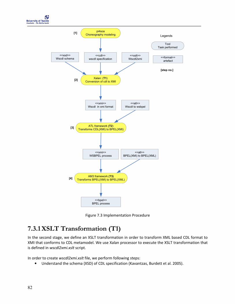
82
<<cdl>>
wscdl specification
pi4soa
Choreography modeling
Tool
Task performed
<<format>>
artefact
<<xsd>>
Wscdl schema
Xalan: (T1)
Conversion of cdl to XMI
<<xslt>>
Wscdl2xmi
<<xmi>>
Wscdl in xmi format
ATL framework (T2)
Transforms CDL(XMI) to BPEL(XMI)
<<atl>>
Wscdl to wsbpel
<<xmi>>
WSBPEL process
AM3 framework (T3)
Transforms BPEL(XMI) to BPEL(XML)
<<atl>>
BPEL(XMI) to BPEL(XML)
<<bpel>>
BPEL process
[step no.]
[1]
[2]
[3]
[4]
Legends
Figure 7.3 Implementation Procedure
7.3.1 XSLT Transformation (T1) In the second stage, we define an XSLT transformation in order to transform XML based CDL format to
XMI that conforms to CDL metamodel. We use Xalan processor to execute the XSLT transformation that
is defined in wscdl2xmi.xslt script.
In order to create wscdl2xmi.xslt file, we perform following steps:
• Understand the schema (XSD) of CDL specification (Kavantzas, Burdett et al. 2005).
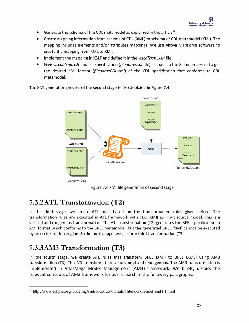
83
• Generate the schema of the CDL metamodel as explained in the article16
.
• Create mapping information from schema of CDL (XML) to schema of CDL metamodel (XMI). The
mapping includes elements and/or attributes mappings. We use Altova MapForce software to
create the mapping from XML to XMI.
• Implement the mapping in XSLT and define it in the wscdl2xmi.xslt file.
• Give wscdl2xmi.xslt and cdl specification (filename.cdl file) as input to the Xalan processor to get
the desired XMI format (filenameCDL.xmi) of the CDL specification that conforms to CDL
metamodel.
The XMI generation process of the second stage is also depicted in Figure 7.4.
wscdl.xsd
<xsd:schema>
</xsd: schema>
wscdxmi.xsd
<xsd:schema>
</xsd: schema>
wscdl2xmi.xslt
xalan
<xmi:cdl>
………..
………...
………..
………...
</xmi:cdl>
<packagel>
………..
………...
………..
………...
</package>
filename.cdl
filenameCDL.xmi
Figure 7.4 XMI file generation of second stage
7.3.2 ATL Transformation (T2) In the third stage, we create ATL rules based on the transformation rules given before. The
transformation rules are executed in ATL framework with CDL (XMI) as input source model. This is a
vertical and exogenous transformation. The ATL transformation (T2) generates the BPEL specification in
XMI format which conforms to the BPEL metamodel, but the generated BPEL (XMI) cannot be executed
by an orchestration engine. So, in fourth stage, we perform third transformation (T3).
7.3.3 AM3 Transformation (T3) In the fourth stage, we create ATL rules that transform BPEL (XMI) to BPEL (XML) using AM3
transformation (T3). This ATL transformation is horizontal and endogenous. The AM3 transformation is
implemented in AtlasMega Model Management (AM3) framework. We briefly discuss the
relevant concepts of AM3 framework for our research in the following paragraphs.
16
http://www.eclipse.org/modeling/emf/docs/1.x/tutorials/xlibmod/xlibmod_emf1.1.html

84
• Atlas Mega Metamodel Framework
AM3 is a Generative Modeling Technologies17
(GMT) subproject which is developed by INIRIA18
. The
global resources like software artifacts, models, file formats, etc. are heterogeneous and widely
distributed. MDE based software development process uses such artifacts and aims to develop
softwares based on chains of model transformations. The modeling process in such a large software
development using MDE is called modeling in large. But the heterogeneity among the global resources
creates difficulty in MDE software development. AM3 is intended to provide support for the modeling in
large, i.e. managing global resources in the field of Model-Driven Engineering (MDE) (Allilaire, Bézivin et
al. 2006). AM3 provides a set of tools and artifacts that allows creating, storing, and modifying such
global resources using the notion of megamodel. A megamodel is a model whose elements are
themselves models.
In our research, we use AM3 plug-in for the following purposes:
• Transforming from XMI model to XML model using Extractors,
• Launching several transformations in batch mode.
• Using XML 1.1metamodel from the AM3 zoo19
.
• XMI-to-XML transformation
In XMI-to-XML transformation, we use a BPEL model (XMI format) as source model and transform it to
BPEL process (XML format) as the target model. We use XML 1.1 metamodel from AM3 zoo. The XML
metamodel is presented in Figure 7.5.
17
http://www.eclipse.org/gmt/ 18
http://www.inria.fr/ 19
http://www.emn.fr/z-info/atlanmod/index.php/Ecore#XML_1.1
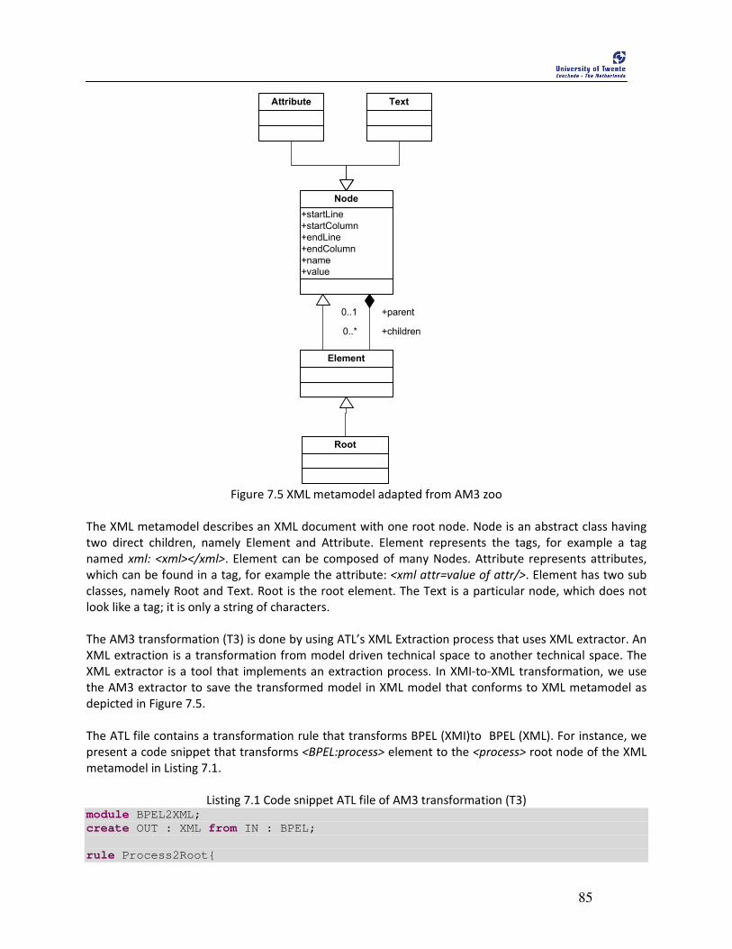
85
+startLine
+startColumn
+endLine
+endColumn
+name
+value
Node
Attribute Text
Element
+parent0..1
+children0..*
Root
Figure 7.5 XML metamodel adapted from AM3 zoo
The XML metamodel describes an XML document with one root node. Node is an abstract class having
two direct children, namely Element and Attribute. Element represents the tags, for example a tag
named xml: <xml></xml>. Element can be composed of many Nodes. Attribute represents attributes,
which can be found in a tag, for example the attribute: <xml attr=value of attr/>. Element has two sub
classes, namely Root and Text. Root is the root element. The Text is a particular node, which does not
look like a tag; it is only a string of characters.
The AM3 transformation (T3) is done by using ATL’s XML Extraction process that uses XML extractor. An
XML extraction is a transformation from model driven technical space to another technical space. The
XML extractor is a tool that implements an extraction process. In XMI-to-XML transformation, we use
the AM3 extractor to save the transformed model in XML model that conforms to XML metamodel as
depicted in Figure 7.5.
The ATL file contains a transformation rule that transforms BPEL (XMI)to BPEL (XML). For instance, we
present a code snippet that transforms <BPEL:process> element to the <process> root node of the XML
metamodel in Listing 7.1.
Listing 7.1 Code snippet ATL file of AM3 transformation (T3) module BPEL2XML;
create OUT : XML from IN : BPEL;
rule Process2Root{
86
from
s : BPEL!Process
to
t : XML!Root(
name <- 'process',
children <- Sequence{xmlns, name, tgnsp, s.partnerLinks,
s.variables, s.scopeElementActivity}
),
xmlns : XML!Attribute(
name <- 'xmlns',
value <- 'http://docs.oasis-
open.org/wsbpel/2.0/process/executable'
),
name : XML!Attribute(
name <- 'name',
value <- s.name ),
tgnsp : XML!Attribute(
name <- 'targetNamespace',
value <- s.targetNameSpace
)
}
In this ATL transformation code, when a <Process> element is found in filename.xmi, then in is
transformed to <process> as root node with xmlns, name, tgnsp as attributes and s.partnerLinks,
s.variables, and s.scopeElementActivity as the relationship.
Let us consider following partial xmi model specification of filenameBPEL.xmi shown in Listing 7.2.
Listing 7.2 Partial BPEL (XMI) model specification
<?xml version="1.0" encoding="UTF-8"?>
<BPEL:Process xmi:version="2.0" xmlns:xmi="http://www.omg.org/XMI" xmlns:xsi="http://www.w3.org/2001/XMLSchema-instance" xmlns:BPEL="uri:BPEL.ecore" name="ManRoleType" targetNameSpace="http://www.pi4soa.org/purchaseOrder"> <!--- process contains other elements -->
</BPEL:Process>
If we run the ATL code of Listing 7.1 in ATL engine then the output will is like as depicted in Listing 7.3
Listing 7.3 Output of the ATL code of Listing 7.1 in ATL engine
<?xml version="1.0" encoding="UTF-8"?>
<Root xmi:version="2.0" xmlns:xmi="http://www.omg.org/XMI" xmlns:xsi="http://www.w3.org/2001/XMLSchema-instance" xmlns="XML" name="process"> <children xsi:type="Attribute" name="xmlns" value= "http://docs.oasis-open.org/wsbpel/2.0/process/executable"/> <children xsi:type="Attribute" name="name" value="ManRoleType"/>
87
<children xsi:type="Attribute" name="targetNamespace" value= " http://www.pi4soa.org/purchaseOrder"/> </Root>
The output of Listing 7.3 is not what we want as the BPEL specification. So, we use AM3 extractor
concept of AM3 framework that transforms the XMI format into XML format with same ATL code
presented in Listing 7.1. We use AM3 plug-in to achieve XMI-to-XML transformation by saving output
models using am3.saveModel extractor of AM3 ant task20
. In Listing 7.4, we present partial code snippet
of ant file that uses am3.saveModel as AM3 extractor. The overall transforamtio chain that includes the
Listing 7.4 is presented in Apendix C. For detail features of AM3 ant task, we refer to the article21
.
Listing 7.4 Code snippet of ant file to show AM3 extractor usages
1 <projet name="xmi2xml"> 2 3 <!-- other tasks --> 4 5 <!-- Transform BPELXMI model into BPELXML model -->
6 <am3.atl path="/test2Bpel/xmi2xml.atl"> 7 <!-- BPELXMI stores filenameBPEL.xmi as input -->
8 <inModel name="IN" model="BPELXMI"/> 9 <inModel name="BPEL" model="BPEL"/> 10 <inModel name="XML" model="XML"/> 11 <!-- BPELxml is an instance of XML metamodel -->
12 <outModel name="OUT" model="BPELxml" metamodel="XML"/> 13 </am3.atl> 14 15 <!-- Extract output model -->
16 <am3.saveModel model="BPELxml" path="/test2Bpel/output/filename.bpel"> 17 <!-- this is the xml extractor -->
18 <extractor name="xml"/> 19 </am3.saveModel> 20 21 </projet>
In Listing 7.4, Line no. 6-13 presents <am3.atl> task that indicates the execution of xmi2xml.atl
transformation file (Listing 7.1) with the required parameters like input and output model and their
respective metamodel. Line no. 16 and 17 shows the use of AM3 XML extractor process using
am3.saveModel. When we run the ant file, it executes the xmi2xml.atl file and saves the output in XML
format. Listing 7.5 presents the output of after running the ant file.
Listing 7.5 BPEL (XML) file after the execution of ant file
<?xml version = '1.0' encoding = 'UTF-8' ?> <process xmlns = 'http://docs.oasis-open.org/wsbpel/2.0/process/executable' name = 'ManRoleType'
targetNamespace = 'http://www.pi4soa.org/purchaseOrder'> </process>
Hence, we achieve the executable bpel process using the AM3 framework.
20
http://wiki.eclipse.org/ATL_Howtos 21
http://wiki.eclipse.org/AM3_Ant_Tasks
88
Relationships with MDA approach
The overall transformation procedure uses two metamodel transformations, as suggested by MDA. The
first metamodel transformation (T2) is vertical and exogenous, which is performed in the third stage and
transforms CDL model (conforming CDL metamodel) to BPEL instance (conforming to BPEL metamodel)
using the transformation rules implemented in ATL transformation language.
The second metamodel transformation (T3) is horizontal and endogenous transformation which is
performed in the fourth stage and transforms the BPEL (XMI )model to BPEL (XML) model. We used AM3
framework to implement and execute the xmi2xml.atl.
The procedure also consists of conversion from XML format to XMI format using XSLT transformation
(T1) in the first stage. This conversion is not considered as MDA model transformations, since this
transformation (T1) converts a model from one format to another. However, T1 can be considered as
bridges between technological spaces (Kurtev, Bézivin et al. 2002). Additionally, the concept of deriving
XML schemas from models presented in (Kurtev, Aksit et al. 2002) is also used in the transformation
procedure, in which the XMI of respective metamodel are generated from the metamodel. The model
serialization process (OMG/XMI 2007) of generation of XMI (i.e. MOF-complaint models) format is also
applied in the transformation procedure.
7.4 Limitations of the proposed approach In this section we discuss the limitations of our proposed approach from two perspectives: 1.
Transformation rules, and 2. Implementation. From the transformation rules perspective, we present
number of cdl constructs that has potential mappings in BPEL but we did not cover in our
transformation mapping because of research time constraint. From implementation perspective, we
explain the limitations that exist in our implementation procedure. The implementation includes the ATL
transformation rules and the implementation procedure.
We present the limitations from both perspectives in following sections.
7.4.1 Transformation Rules
• cdl:timeout mapping
The cdl:timeout construct is present inside the cdl:interaction activity which specifies the time
frame within which an interaction must complete after it is initiated. The transformation
mapping from CDL to BPEL presented in (Mendling and Hafner 2008) suggests to map
cdl:timeout to one of the following: bpel:pick, bpel:onMessage, or bpel:onAlarm. In our
transformation, we did not present the mapping of cdl:timeout construct. We did not this
mapping because of time limitation.
• cdl:choice mapping
The transformation mapping from CDL to BPEL in presented in (Rosenberg, Enzi et al. 2007)
suggests another mapping for cdl:choice in addition of Section 7.2. In the mapping, Rosenberg
et al. suggest that cdl:choice can also be mapped to bpel:onMessage nested in bpel:pick with a
89
condition. We did not present the mapping of cdl:choice in our transformation mapping
because of time limitation.
• cdl:perform mapping
cdl:perform is used to combine existing choreographies to create new ones. So, we view
cdl:perform as a construct for recursive composition of choreographies to include sub-
choreographies. There is no explicit construct that can express the recursive composition of
BPEL processes to create sub-process. Hence, we did not further investigate the mapping of
cdl:perform. However, there was an attempt to include sub-process in BPEL process
(Kloppmann, Koenig et al. 2005), but unfortunately it is not implemented yet.
7.4.2 Implementation
• Condition modeling
While performing the transformation, in most of the cases we have to manually define the
condition. For instance, <condition> processing is done manually. We model condition as
attribute in BPEL constructs (See Figure 6.3) that require condition and manually provide the
necessary conditional decisions. In the process of transformation, whenever we encounter the
condition, we put “default=0” message inside the condition and for readability, we indicate it
with comment as “<!-- Input the condition -- >”. This message indicates that the condition
should be provided manually.
• The application scenarios do not include the concepts of compensation, fault, and error
handling. With this regards, we still consider our application scenario to be incomplete to verify
the transformation of respective mapping.
• In case of CDL, we do not include Expressions that includes predicate to specify conditions.
Since, we already stated that we manually provide the conditional information so we do not
focus on expression. However, excluding expression can be a problem sometime, especially
when the constructs use CDL supplied functions like getCurrentTime(), getCurrentDate(),
isVariableAvailable) because these functions do not have corresponding mapping functions in
BPEL. In these cases also we manually input the necessary information.
• The transformation mappings from CDL to BPEL constructs do not have any formal proof and the
choices of mapping rely on semantics of the constructs, in-depth analysis of the constructs and
are supported by earlier researches.
• We do not have any formal reasoning for the correctness of the transformation in terms of
choreography conformance i.e. the generated orchestration conforms to the choreography.
However, we claim the correctness of the transformation based on the goal achieved by the
initiator (see Figure 4.6). We observe the behavior of the generated orchestration and match it
with the behavior of the choreography and claim the correctness if both refer to the goal of the
initiator.

90
91
8 Validation and Evaluation
n this chapter, we evaluate the results of our research by validating and comparing our approach with other three closely related developments that aim to transform the choreography to orchestration. Initially, we validate our approach with the PurchaseOrder
application scenario and later with a new application scenario, adopted from one of the related works. We also present the comparison of our approach with other related developments.
This chapter is structured as follows: Section 8.1 describes the validation strategy of the results of our approach. We include two application scenarios and validate our approach based on those application scenarios. Section 8.2 presents some of the related developments that aim to transform choreography to orchestration. Section 8.3 compares our work with these related developments.
8.1 Validation strategy In this section, we present the validation of the results of our proposed approach. We validate our
approach in a pragmatic way by taking the behavior of the input choreography and observing if the
expected behavior is shown by the generated BPEL process.
We also validate the generated BPEL process against the WSBPEL executable schema22
. Prior, to this
validation, we first add the necessary information to the generated BPEL process manually according the
discussion presented in Section 7.2. We explicitly need to add the necessary information to the
generated BPEL process because the input CDL specification does not contain the internal details of
individual service. But, the BPEL process needs those service specific private information. After
successfully validating against the schema, we also import the generated BPEL process in the ActiveBPEL
designer to check if the designer can visualize the BPEL process. The ActiveBPEL designer generates the
activities according to the specification of generated BPEL process which enables us to validate the
behavior of the generated process visually.
8.1.1 PurchaseOrder application scenario The behavior of the manufacturer department, as an orchestrator is shown in Figure 4.4 as a sequence
diagram. The behavior of the choreography specification can be briefly presented as follows: the
SalesDept calls the ManufacturerDept, which in turn invokes the StockDept to check stock for the
requested good. In turn, the ManufacturerDept receives message from the StockDept about the
requested good. The ManufaturerDept, then concurrently calls the ShipmentDept and the BillingDept
and receives message from them. Finally, the ManufacturerDept replies to the SalesDept about the
purchaseOrder. The choreography specification of PurchaseOrder scenario is presented in Appendix C.
The PurchaseOrder application scenario contains the interaction activities. So we use this application
scenario to validate the behavior of interaction activities of the CDL with the behavior of the generated
BPEL process. In Section 8.1.2, we present another application scenario in which we include other
22
http://docs.oasis-open.org/wsbpel/2.0/CS01/process/executable/ws-bpel_executable.xsd
I

92
structural activities like variations in <workunit> construct, <choice> construct, <assign> activities, and
so on in the CDL specification along with the interaction activities.
In order to validate the generated BPEL code of the orchestrator, i.e., the ManufacturerDept of
PurchaseOrder against the BPEL executable schema, we have to manually add some of the missing
values of the attributes. The following information was manually added before validating the BPEL
process against the schema.
• portType:
The value of bpel:portType attribute of <invoke>, <receive>, and <reply> activities of BPEL
process refers to the wsdl:portType of the WSDL file in which the service is specified. Since, we
do not have the respective WSDL files, we manually put ”WSDL:portType” as default values.
We later replace the value by the actual wsdl:portTypes. For readability, we have included the
comment ”Need to change with wsdl:portType” in the BPEL process.
The ManufacturerDept.bpel process is shown in Listing 8.1.
Listing 8.1 ManufacturerDept.bpel of PurchaseOrder application scenario
<?xml version="1.0" encoding="UTF-8"?>
<process xmlns ='http://docs.oasis-open.org/wsbpel/2.0/process/executable'
name = 'ManufacturerDeptProcess'
targetNamespace = 'http://www.pi4soa.org/purchaseOrder'>
<partnerLinks>
<partnerLink name="ManufacturerDeptParticipantType"
myRole="ManufacturerDeptParticipantRole"
partnerLinkType=”ManufacturerDeptParticipantLT"/>
<partnerLink name="BillingDeptParticipantType"
partnerRole=" BillingDeptParticipantRole "
partnerLinkType=" BillingDeptParticipant "/>
<partnerLink name="SalesDeptParticipantType"
partnerRole=" SalesDeptParticipantRole"
partnerLinkType="SalesDeptParticipantLT"/>
<partnerLink name="ShipmentDeptParticipantType"
partnerRole=" ShipmentDeptParticipantRole"
partnerLinkType=" ShipmentDeptParticipantLT"/>
<partnerLink name="StockDeptParticipantType"
partnerRole=" StockDeptParticipantRole"
partnerLinkType="StockDeptParticipantLT"/>
</partnerLinks>
<variables>
<variable name="BillingChannelInstance" messageType=" BillingChannelInstance"/>
<variable name="BillingInfo" messageType=" BillingInfo "/>
<variable name="BillingInfoResponse" messageType=" BillingInfoResponse "/>
<variable name="GoodStockInfo" messageType=" GoodStockInfo "/>
<variable name="GoodStockResponse" messageType="GoodStockResponse "/>
<variable name="ManufacturerChannel" messageType="ManufacturerChannel "/>
<variable name="POChannel" messageType="POChannel "/>
<variable name="POResponse" messageType="POResponse "/>
<variable name="ShipmentChannelInstance" messageType=" ShipmentChannelInstance"/>
<variable name="ShipmentInfo" messageType="ShipmentInfo "/>
<variable name="ShipmentInfoResponse" messageType="ShipmentInfoResponse"/>
<variable name="StockChannelInstance" messageType="StockChannelInstance"/>
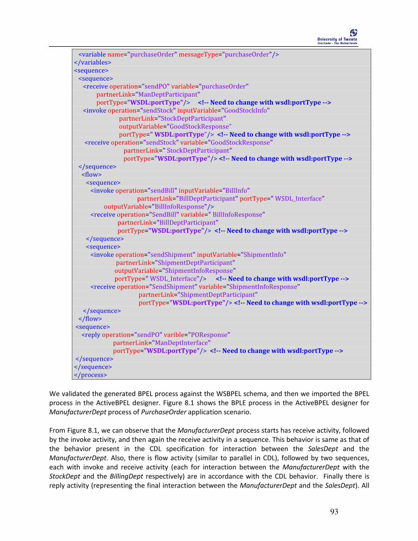
93
<variable name="purchaseOrder" messageType="purchaseOrder"/>
</variables>
<sequence>
<sequence>
<receive operation="sendPO" variable="purchaseOrder"
partnerLink="ManDeptParticipant"
portType="WSDL:portType"/> <!-- Need to change with wsdl:portType -->
<invoke operation="sendStock" inputVariable="GoodStockInfo"
partnerLink="StockDeptParticipant"
outputVariable="GoodStockResponse”
portType=" WSDL:portType”/> <!-- Need to change with wsdl:portType -->
<receive operation="sendStock" variable="GoodStockResponse"
partnerLink=" StockDeptParticipant"
portType="WSDL:portType"/> <!-- Need to change with wsdl:portType -->
</sequence>
<flow>
<sequence>
<invoke operation="sendBill" inputVariable="BillInfo"
partnerLink="BillDeptParticipant" portType=" WSDL_Interface"
outputVariable="BillInfoResponse"/>
<receive operation="SendBill" variable=" BillInfoResponse"
partnerLink="BillDeptParticipant"
portType="WSDL:portType"/> <!-- Need to change with wsdl:portType -->
</sequence>
<sequence>
<invoke operation="sendShipment" inputVariable="ShipmentInfo"
partnerLink="ShipmentDeptParticipant"
outputVariable="ShipmentInfoResponse"
portType=" WSDL_Interface"/> <!-- Need to change with wsdl:portType -->
<receive operation="SendShipment" variable="ShipmentInfoResponse"
partnerLink="ShipmentDeptParticipant"
portType="WSDL:portType"/> <!-- Need to change with wsdl:portType -->
</sequence>
</flow>
<sequence>
<reply operation="sendPO" varible="POResponse"
partnerLink="ManDeptInterface"
portType="WSDL:portType"/> <!-- Need to change with wsdl:portType -->
</sequence>
</sequence>
</process>
We validated the generated BPEL process against the WSBPEL schema, and then we imported the BPEL
process in the ActiveBPEL designer. Figure 8.1 shows the BPLE process in the ActiveBPEL designer for
ManufacturerDept process of PurchaseOrder application scenario.
From Figure 8.1, we can observe that the ManufacturerDept process starts has receive activity, followed
by the invoke activity, and then again the receive activity in a sequence. This behavior is same as that of
the behavior present in the CDL specification for interaction between the SalesDept and the
ManufacturerDept. Also, there is flow activity (similar to parallel in CDL), followed by two sequences,
each with invoke and receive activity (each for interaction between the ManufacturerDept with the
StockDept and the BillingDept respectively) are in accordance with the CDL behavior. Finally there is
reply activity (representing the final interaction between the ManufacturerDept and the SalesDept). All

94
these behaviors are similar and are in accordance with the behavior specified in the CDL specification.
This validates that the generated BPEL process conforms to the choreography specification.
Figure 8.1 The ActiveBPEL process of ManufacturerDept process
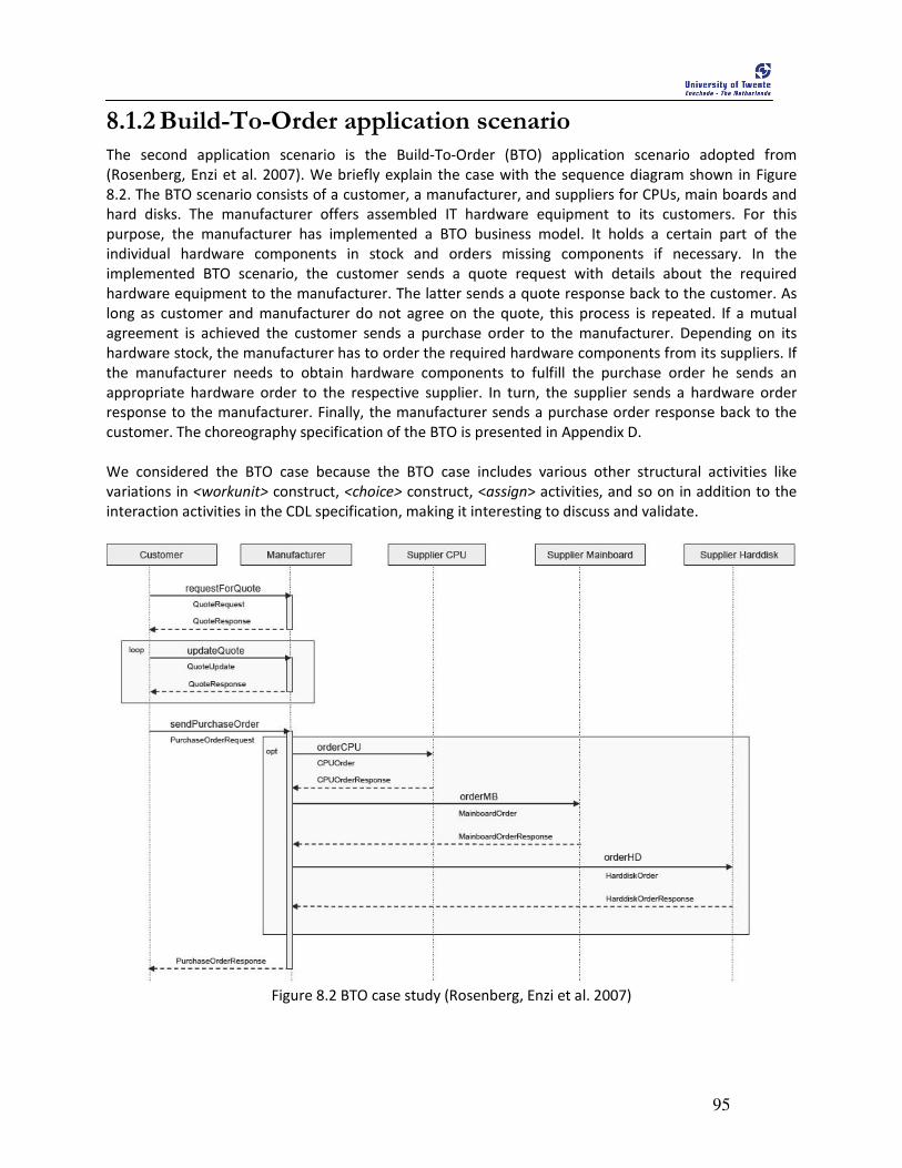
95
8.1.2 Build-To-Order application scenario The second application scenario is the Build-To-Order (BTO) application scenario adopted from
(Rosenberg, Enzi et al. 2007). We briefly explain the case with the sequence diagram shown in Figure
8.2. The BTO scenario consists of a customer, a manufacturer, and suppliers for CPUs, main boards and
hard disks. The manufacturer offers assembled IT hardware equipment to its customers. For this
purpose, the manufacturer has implemented a BTO business model. It holds a certain part of the
individual hardware components in stock and orders missing components if necessary. In the
implemented BTO scenario, the customer sends a quote request with details about the required
hardware equipment to the manufacturer. The latter sends a quote response back to the customer. As
long as customer and manufacturer do not agree on the quote, this process is repeated. If a mutual
agreement is achieved the customer sends a purchase order to the manufacturer. Depending on its
hardware stock, the manufacturer has to order the required hardware components from its suppliers. If
the manufacturer needs to obtain hardware components to fulfill the purchase order he sends an
appropriate hardware order to the respective supplier. In turn, the supplier sends a hardware order
response to the manufacturer. Finally, the manufacturer sends a purchase order response back to the
customer. The choreography specification of the BTO is presented in Appendix D.
We considered the BTO case because the BTO case includes various other structural activities like
variations in <workunit> construct, <choice> construct, <assign> activities, and so on in addition to the
interaction activities in the CDL specification, making it interesting to discuss and validate.
Figure 8.2 BTO case study (Rosenberg, Enzi et al. 2007)
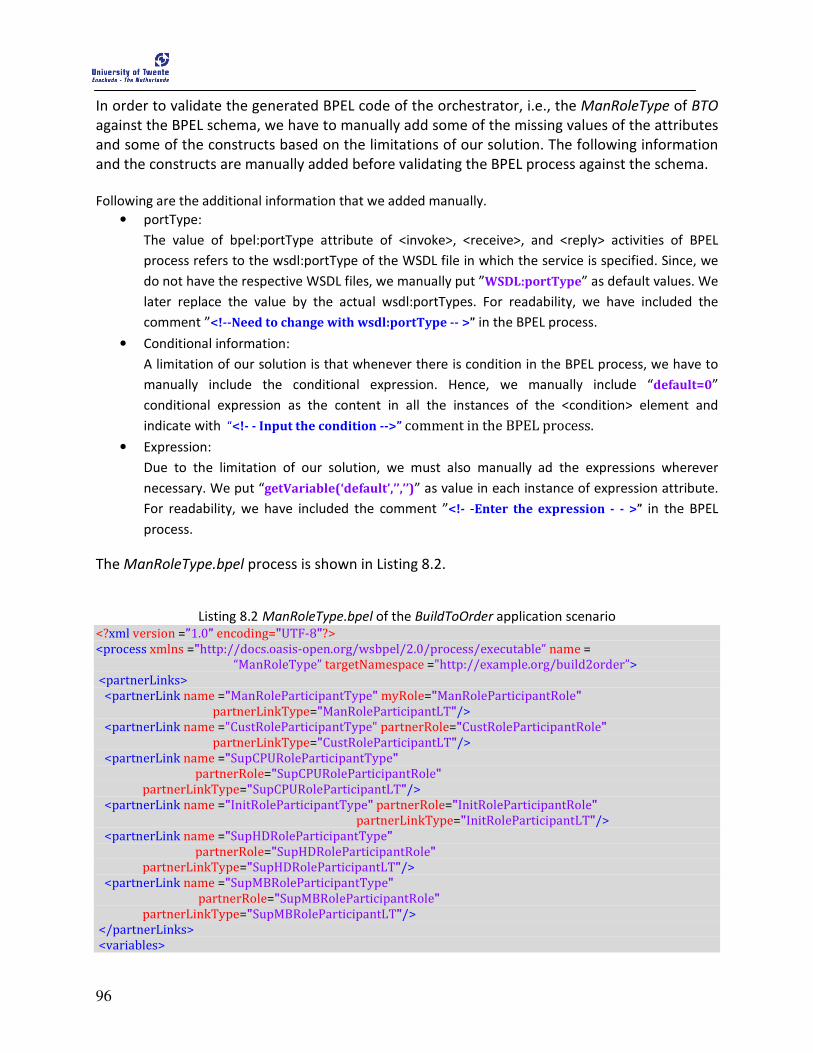
96
In order to validate the generated BPEL code of the orchestrator, i.e., the ManRoleType of BTO
against the BPEL schema, we have to manually add some of the missing values of the attributes
and some of the constructs based on the limitations of our solution. The following information
and the constructs are manually added before validating the BPEL process against the schema.
Following are the additional information that we added manually.
• portType:
The value of bpel:portType attribute of <invoke>, <receive>, and <reply> activities of BPEL
process refers to the wsdl:portType of the WSDL file in which the service is specified. Since, we
do not have the respective WSDL files, we manually put ”WSDL:portType” as default values. We
later replace the value by the actual wsdl:portTypes. For readability, we have included the
comment ”<!--Need to change with wsdl:portType -- >” in the BPEL process.
• Conditional information:
A limitation of our solution is that whenever there is condition in the BPEL process, we have to
manually include the conditional expression. Hence, we manually include “default=0”
conditional expression as the content in all the instances of the <condition> element and
indicate with “<!- - Input the condition -->” comment in the BPEL process.
• Expression:
Due to the limitation of our solution, we must also manually ad the expressions wherever
necessary. We put “getVariable(‘default’,’’,’’)” as value in each instance of expression attribute.
For readability, we have included the comment ”<!- -Enter the expression - - >” in the BPEL
process.
The ManRoleType.bpel process is shown in Listing 8.2.
Listing 8.2 ManRoleType.bpel of the BuildToOrder application scenario
<?xml version =”1.0” encoding="UTF-8"?>
<process xmlns ="http://docs.oasis-open.org/wsbpel/2.0/process/executable” name =
“ManRoleType” targetNamespace ="http://example.org/build2order”>
<partnerLinks>
<partnerLink name ="ManRoleParticipantType" myRole="ManRoleParticipantRole"
partnerLinkType="ManRoleParticipantLT"/>
<partnerLink name ="CustRoleParticipantType" partnerRole="CustRoleParticipantRole"
partnerLinkType="CustRoleParticipantLT"/>
<partnerLink name ="SupCPURoleParticipantType"
partnerRole="SupCPURoleParticipantRole"
partnerLinkType="SupCPURoleParticipantLT"/>
<partnerLink name ="InitRoleParticipantType" partnerRole="InitRoleParticipantRole"
partnerLinkType="InitRoleParticipantLT"/>
<partnerLink name ="SupHDRoleParticipantType"
partnerRole="SupHDRoleParticipantRole"
partnerLinkType="SupHDRoleParticipantLT"/>
<partnerLink name ="SupMBRoleParticipantType"
partnerRole="SupMBRoleParticipantRole"
partnerLinkType="SupMBRoleParticipantLT"/>
</partnerLinks>
<variables>
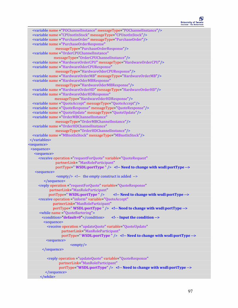
97
<variable name ="POChannelInstance" messageType="POChannelInstance"/>
<variable name ="CPUnotInStock" messageType="CPUnotInStock"/>
<variable name ="PurchaseOrder" messageType="PurchaseOrder"/>
<variable name ="PurchaseOrderResponse"
messageType="PurchaseOrderResponse"/>
<variable name ="OrderCPUChannelInstance"
messageType="OrderCPUChannelInstance"/>
<variable name ="HardwareOrderCPU" messageType="HardwareOrderCPU"/>
<variable name ="HardwareOderCPUResponse"
messageType="HardwareOderCPUResponse"/>
<variable name ="HardwareOrderMB" messageType="HardwareOrderMB"/>
<variable name ="HardwareOderMBResponse"
messageType="HardwareOderMBResponse"/>
<variable name ="HardwareOrderHD" messageType="HardwareOrderHD"/>
<variable name ="HardwareOderHDResponse"
messageType="HardwareOderHDResponse"/>
<variable name ="QuoteAccept" messageType="QuoteAccept"/>
<variable name ="QuoteResponse" messageType="QuoteResponse"/>
<variable name ="QuoteUpdate" messageType="QuoteUpdate"/>
<variable name ="OrderMBChannelInstance"
messageType="OrderMBChannelInstance"/>
<variable name ="OrderHDChannelInstance"
messageType="OrderHDChannelInstance"/>
<variable name ="MBnotInStock" messageType="MBnotInStock"/>
</variables>
<sequence>
<sequence>
<sequence>
<receive operation ="requestForQuote" variable="QuoteRequest"
partnerLink= "ManRoleParticipant"
portType=" WSDL:portType " /> <!-- Need to change with wsdl:portType -->
<sequence>
<empty/> <!-- the empty construct is added -->
</sequence>
<reply operation ="requestForQuote" variable="QuoteResponse"
partnerLink="ManRoleParticipant"
portType=" WSDL:portType " /> <!-- Need to change with wsdl:portType -->
<receive operation ="inform" variable="QuoteAccept"
partnerLink="ManRoleParticipant"
portType=" WSDL:portType " /> <!-- Need to change with wsdl:portType -->
<while name ="QuoteBartering">
<condition>"default=0"</condition> <!- - Input the condition -->
<sequence>
<receive operation ="updateQuote" variable="QuoteUpdate"
partnerLink="ManRoleParticipant"
portType=" WSDL:portType " /> <!-- Need to change with wsdl:portType -->
<sequence>
<empty/>
</sequence>
<reply operation ="updateQuote" variable="QuoteResponse"
partnerLink="ManRoleParticipant"
portType="WSDL:portType" /> <!-- Need to change with wsdl:portType -->
</sequence>
</while>

98
</sequence>
<receive operation ="sendPurchaseOrder" variable="PurchaseOrder"
partnerLink="ManRoleParticipant"
portType="WSDL:portType" /> <!-- Need to change with wsdl:portType -->
<sequence>
<flow name ="parallel">
<sequence>
<if name ="Choice_CPUnotInStock">
<condition>”default=0”</condition> <!- - Input the condition -->
<sequence>
<invoke operation ="orderCPU" inputVariable="HardwareOrderCPU"
partnerLink="ManRoleParticipant"
outputVariable="HardwareOrderCPUResponse"
portType="WSDL:portType" /> <!-- Need to change with wsdl:portType -->
</sequence>
<else>
<sequence>
<assign>
<copy>
<from variable=”HardwareOrderCPU” />
<to expression=" getVariable(‘default’,’’,’’)"/> <!- -Enter the expression - - >
</copy>
</assign>
</sequence>
</else>
</if>
</sequence>
<sequence>
<empty/>
</sequence>
</sequence>
<sequence>
<if name ="Choice_HDnotInStock">
<condition>"default=0" </condition> <!- - Input the condition -->
<sequence>
<invoke operation ="orderCPU" inputVariable="HardwareOrderHD"
partnerLink="ManRoleParticipant"
outputVariable="HardwareOrderHDResponse"
portType="WSDL:portType"/> <!-- Need to change with wsdl:portType -->
<else>
<sequence>
<assign>
<copy>
<from expression=" getVariable(‘default’,’’,’’)" /> <!- -Enter the expression - - >
<to variable=" HardwareoderHDResposne " />
</copy>
</assign>
</sequence>
</else>
<sequence>
</if>
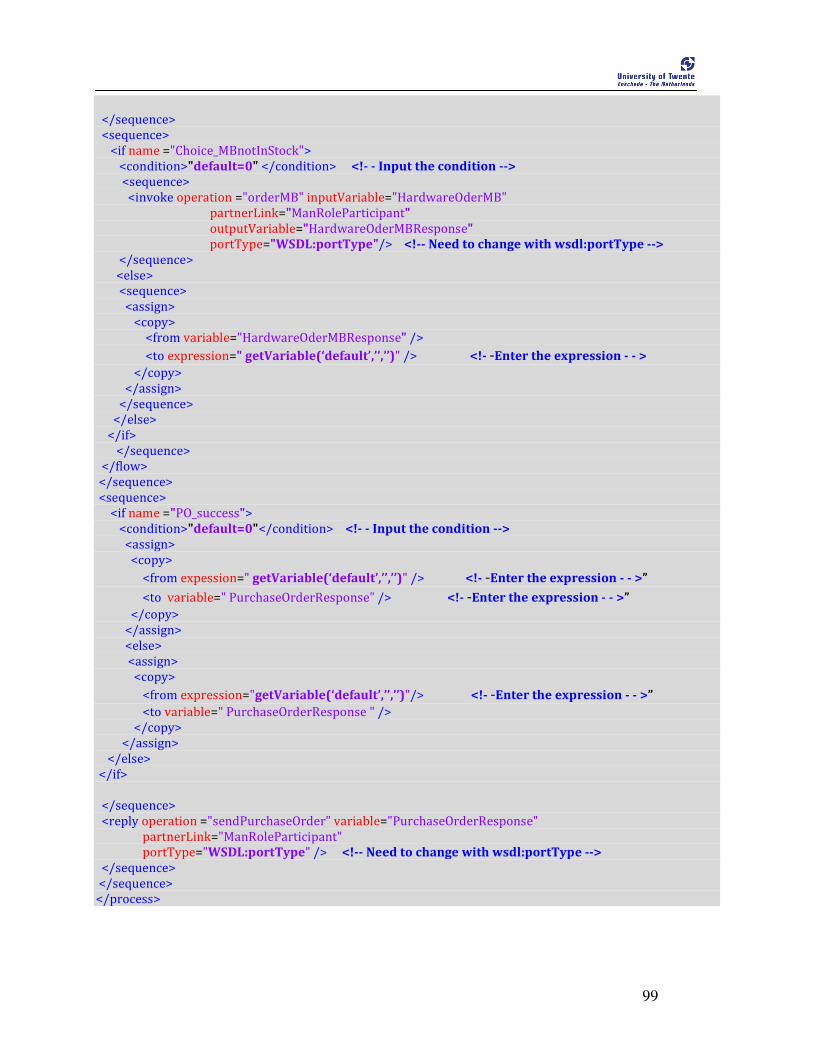
99
</sequence>
<sequence>
<if name ="Choice_MBnotInStock">
<condition>"default=0" </condition> <!- - Input the condition -->
<sequence>
<invoke operation ="orderMB" inputVariable="HardwareOderMB"
partnerLink="ManRoleParticipant"
outputVariable="HardwareOderMBResponse"
portType="WSDL:portType"/> <!-- Need to change with wsdl:portType -->
</sequence>
<else>
<sequence>
<assign>
<copy>
<from variable="HardwareOderMBResponse" />
<to expression=" getVariable(‘default’,’’,’’)" /> <!- -Enter the expression - - >
</copy>
</assign>
</sequence>
</else>
</if>
</sequence>
</flow>
</sequence>
<sequence>
<if name ="PO_success">
<condition>"default=0"</condition> <!- - Input the condition -->
<assign>
<copy>
<from expession=" getVariable(‘default’,’’,’’)" /> <!- -Enter the expression - - >”
<to variable=" PurchaseOrderResponse" /> <!- -Enter the expression - - >”
</copy>
</assign>
<else>
<assign>
<copy>
<from expression="getVariable(‘default’,’’,’’)"/> <!- -Enter the expression - - >”
<to variable=" PurchaseOrderResponse " />
</copy>
</assign>
</else>
</if>
</sequence>
<reply operation ="sendPurchaseOrder" variable="PurchaseOrderResponse"
partnerLink="ManRoleParticipant"
portType="WSDL:portType" /> <!-- Need to change with wsdl:portType -->
</sequence>
</sequence>
</process>
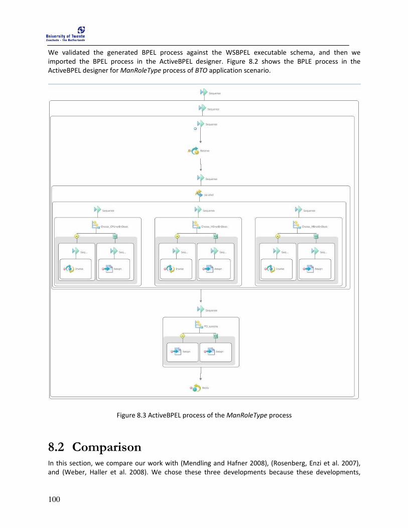
100
We validated the generated BPEL process against the WSBPEL executable schema, and then we
imported the BPEL process in the ActiveBPEL designer. Figure 8.2 shows the BPLE process in the
ActiveBPEL designer for ManRoleType process of BTO application scenario.
Figure 8.3 ActiveBPEL process of the ManRoleType process
8.2 Comparison In this section, we compare our work with (Mendling and Hafner 2008), (Rosenberg, Enzi et al. 2007),
and (Weber, Haller et al. 2008). We chose these three developments because these developments,
101
similarly to ours, aim to transform a given CDL specification to a BPEL process. The comparison has two
objectives: 1. we want to investigate in which respect and according to which criteria our approach is
more promising than the other developments; 2. In case our approach misses some important criteria,
we can consider these criteria for future work. We initially explain each of these developments in the
following sections and finally compare each of them with our approach. In order to make this
comparison, we considered the following of criteria:
• Transformation implementation: Under this criterion, we consider the implementation
technology that each approach used to implement the transformation. (Sendall and Kozaczynski
2003) distinguished three categories of model transformation approaches: direct model
manipulation, intermediate representation, and transformation language support. The authors
also explained the benefits and drawbacks of each approach. In our comparison, we consider
the benefits and drawbacks presented in (Sendall and Kozaczynski 2003) and we indicate which
approach is the most promising.
• Additional artifact generation: Apart from BPEL process generation, we indicate if each
approach generates any other relevant documents for service composition. For instance,
generation of WSDL specifications from CDL specifications can be significant because BPEL
process uses the WSDL port information in order to interact and communicate with other
services.
• Bi-directional transformation: Under this criterion, we indicate if the transformation is bi-
directional (i.e., if the approach also supports the transformation from orchestration to
choreography). We consider bi-directional transformation as an important criterion because in
collaborative business, the collaborating participants might also be interested in including new
participants in the collaboration. In this case, the collaborating participants may publish their
interface information such that the new participants can use the interface to establish the
collaboration. In order to generate the interface from the collaborating participants, their
orchestration has to be transformed to a choreography and published in the registry. Hence, a
bi-directional transformation in order to generate a choreography from an orchestration.
• Additional transformation details: Due to the difference in information content in
choreography and orchestration, the service specific details have to be added in the generated
BPEL process. Under this criterion, we indicate whether such service specific details are injected
in the process of transformation or manually added to the target model beforehand.
8.2.1 Mendling and Hafner 2008 In (Mendling and Hafner 2008), the transformation from a CDL specification to a BPEL process is
presented in which the choreography is viewed from two aspects, namely as a global and a local
choreography. The global choreography corresponds to the message exchange from a global perspective
and is mentioned as the coordination protocol, while the local choreography corresponds to the
message exchange from the perspective of a single party. The authors have devised a way of generating
a local choreography from a global choreography, and later to use the local choreography to generate
an orchestration process for each party. The detailed mappings of the relevant constructs are provided
with an illustrative example. These mappings are then later implemented in a recursive XSLT script as a
proof-of-concept to realize the transformation. Based on the mappings from CDL to BPEL, the potential
incompatibilities of both languages are also discussed. The transformation process generates the BPEL

102
process for all participants. The process of generation of BPEL process from global choreography is
depicted in Figure 8.4.
Figure 8.4 Transformation process of (Mendling and Hafner 2008)
Benefits
• The main advantage of this approach is the bi-directional transformation, i.e., the
transformation is defined from CDL to BPEL, and vice-versa. The transformation generates the
BPEL process for all involved parties.
• The CDL to BPEL mapping is documented and explained with an illustrative example using an
application scenario.
Drawbacks
• The transformation is at language specification level and the architectural relationship between
choreography and orchestration is not explicitly mentioned.
• The transformation uses a recursive XSLT transformation, which is used for generating XML
documents out of XML source documents. Using an XSLT transformation requires experience
and considerable effort to define even simple transformations (Sendall and Kozaczynski 2003),
and, more importantly, XSLT transformations are often extremely verbose (White 2002).
• There is no transformation mapping information for bpel:invoke activity, which is one of the
important interactivities.
8.2.2 Rosenberg, Enzi et al. 2007 In (Rosenberg, Enzi et al. 2007), a top-down modeling approach to generate a BPEL process from a given
CDL specification is presented. The transformation methodology also considers Service Level
Agreements (SLAs), which are defined as annotations to the CDL specification and are transformed into
policies that can be enforced by a BPEL engine during execution. In addition, the BPEL specifications are
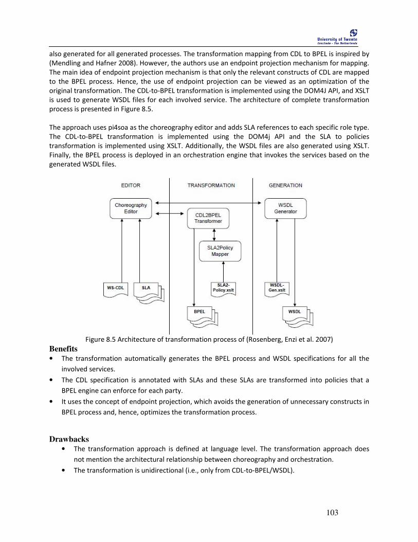
103
also generated for all generated processes. The transformation mapping from CDL to BPEL is inspired by
(Mendling and Hafner 2008). However, the authors use an endpoint projection mechanism for mapping.
The main idea of endpoint projection mechanism is that only the relevant constructs of CDL are mapped
to the BPEL process. Hence, the use of endpoint projection can be viewed as an optimization of the
original transformation. The CDL-to-BPEL transformation is implemented using the DOM4J API, and XSLT
is used to generate WSDL files for each involved service. The architecture of complete transformation
process is presented in Figure 8.5.
The approach uses pi4soa as the choreography editor and adds SLA references to each specific role type.
The CDL-to-BPEL transformation is implemented using the DOM4j API and the SLA to policies
transformation is implemented using XSLT. Additionally, the WSDL files are also generated using XSLT.
Finally, the BPEL process is deployed in an orchestration engine that invokes the services based on the
generated WSDL files.
Figure 8.5 Architecture of transformation process of (Rosenberg, Enzi et al. 2007)
Benefits
• The transformation automatically generates the BPEL process and WSDL specifications for all the
involved services.
• The CDL specification is annotated with SLAs and these SLAs are transformed into policies that a
BPEL engine can enforce for each party.
• It uses the concept of endpoint projection, which avoids the generation of unnecessary constructs in
BPEL process and, hence, optimizes the transformation process.
Drawbacks
• The transformation approach is defined at language level. The transformation approach does
not mention the architectural relationship between choreography and orchestration.
• The transformation is unidirectional (i.e., only from CDL-to-BPEL/WSDL).

104
8.2.3 Weber, Haller et al. 2008 Unlike the other approaches, (Weber, Haller et al. 2008) initially discuss the relationship between
choreography and executable business process (orchestration in our terminology) and then presents
their CDL to BPEL transformation in the context of a virtual organization, which is possibly also
applicable to other domains. The research also introduces the concept of information gap, which is the
term used to mention the different levels of details between a choreography and an orchestration, and
indicates that the sum of orchestrations contains more knowledge than the choreography they
implement. Given a choreography, the approach generates executable processes for each role, with the
respective WSDL specification. The transformation is implemented as Java-based Web Services. The
Knowledge base stores the private information of the individual services and is implemented as a
relational database. The transformation process is depicted in Figure 8.6. The numbering indicates the
sequence of the procedures to be followed in the transformation process.
Figure 8.6 The transformation process of (Weber, Haller et al. 2008)
Benefits
• Unlike other approaches, the transformation explicitly presents and discusses the relationship
between choreography and orchestration. The difference between the information present in a
choreography and an orchestration is defined as the Information Gap.
• The transformation automatically generates the BPEL process for each role in CDL and the
corresponding WSDL files.
• The implementation of transformation algorithm also detects the errors or violated constraints
(e.g., violation of cardinality constraints among the concepts of CDL) that are applicable in CDL.
Disadvantages
• The transformation in unidirectional.

105
Table 3 summarizes the comparison of aforementioned approaches with our proposed approach.
Table 3 Comparison among the available approaches
Features (Mendling and
Hafner 2005)
approach
(Rosenberg, Enzi
et al. 2007)
approach
(Weber, Haller et
al. 2008) approach
Our approach
Transformation
implementation
XSLT based
implementation
DOM4J API and
XSLT
implementation
Java Web service
based
implementation
Metamodel
transformation,
ATL based
implementation
Additional artifact
generation
partnerLinkTypes
and propertyAlias
definition files
WSDL WSDL WSDL is not
generated
Bi-directional
transformation
Supports No support No support No support
Additional
transformation
details
Manually specified
in generated BPEL
process
Manually specified
in generated BPEL
process
Added in the
transformation
process
Manually specified
in generated BPEL
process
Based the discussion of these different approaches, we conclude that our approach is promising in
terms of the transformation implementation. We used metamodel transformation, in which we defined
the abstract syntax of both source and target models in the CDL and BPEL metamodels, respectively. The
relationships between source and target model are defined as transformation mappings, and we
implemented these mappings in the ATL. Our approach falls under the “Transformation language
support” category as described in (Sendall and Kozaczynski 2003) while the transformation
implementation of (Mendling and Hafner 2005) falls under “Intermediate representation”, and the
remaining two falls under “Direct model manipulation”. The transformation language support category
uses a language that provides a set of constructs for explicitly expressing, composing, and applying
transformation. In our approach, ATL is the language used for expressing the transformation. Our
approach uses metamodels to express the mapping from source model to target model at a higher level
of abstraction when compared with other two approaches. XSLT-based transformations require
experience and considerable effort to define and maintain. Transformations written using general-
purpose programming language also lack the necessary abstraction levels and tend to be hard to write,
comprehend, and maintain.
Regarding additional artifact generation and bi-directional transformation criteria, our approach still can
be extended to generate WSDL specifications from the CDL specification. The mapping of CDL-to-WSDL
is presented in (Rosenberg, Enzi et al. 2007) and (Weber, Haller et al. 2008). Further, the support for bi-
directional transformation can also significantly improve our transformation approach. From this
comparison, we consider the WSDL generation and bi-directional transformation as our major topics for
future work.
In (Weber, Haller et al. 2008), the authors determine the service specific information in design time and
put it in the database such that later these information are used at the time of transformation. In all
remaining approaches, such information is manually specified in generated BPEL process. We can
enhance our approach using the concept of marking, as suggested by MDA, to include those service
specific information in the transformation process.

106
107
9 Conclusion
his chapter concludes our research by answering the previously formulated research questions, identifying our scientific contributions and exploring some possible
directions for future work.
This chapter is structured as follows: Section 9.1 provides answers to our research questions, Section 9.2 explains the scientific contribution of this research and Section 9.3 identifies some potential topics for future work.
9.1 Answers to Research Questions This thesis describes an approach to transform a choreography into a set of related orchestrations using
model-driven technology, in this way contributing to the model-driven development of service
composition. In particular, we presented a possible solution that (semi-) automatically transforms a
given choreography to a set of orchestrations. We initially pointed out the motivation for the need of
this (semi-)automatic transformation and explored the architectural relationships between the
choreography and orchestration as architectural patterns. We consider these architectural patterns as
one of our main contributions, in which we identified two possible ways of transforming a given
choreography to a set of orchestrations. The architectural patterns are further used to derive
requirements for transformation specifications, such that these specifications are again used to define
transformation mappings between CDL and BPEL at the language level.
Our objective has been to assess the feasibility of using model-driven technology, in particular
metamodel-based transformations, to achieve the transformation from a choreography to
orchestrations. We chose CDL and BPEL as specification languages for choreography and orchestration,
respectively. We developed metamodels for CDL and BPEL and we implemented the transformation
mappings using ATL as transformation language, which when executed in an ATL engine transforms a
given CDL specification to a centralized BPEL orchestration process. A single ATL transformation is not
sufficient to transform CDL to BPEL, because of the differences between the CDL and BPEL schemas and
the internal representation of these models in ATL. For instance, the ATL engine reads the input model
in XMI serialized format while the CDL specification and BPEL process are based on XML. So, we
implement a transformation chain as a proof-of-concept that transforms a CDL specification to a BPEL
process that can be executed by an orchestration engine. However, due to the difference in abstraction
level and the difference in objectives of choreography and orchestration, some additional information
has to be added manually to the generated orchestration process. The validation of our proposed
approach in two application scenarios reveals that the use of model-based transformation technology,
in particular the definition a metamodel-based transformation, can (semi-) automate the transformation
from a choreography to orchestrations and speed up the service composition process, hence
contributing to the model-driven development of service compositions.
Below we reflect on the results of our research by explicitly answering each research question presented
in Chapter 1.
T
108
RQ1: What are the possible views through which we can realize service composition?
Choreography and orchestration are the two possible views that are at different abstraction levels
through which we can realize service composition. A choreography specifies the observable public
message exchanges, rules of interaction and agreements between the collaborating services from
a global view. A choreography is the decentralized perspective of the service composition that
describes “what” is to be done to achieve a common business goal. In contrast, an orchestration
specifies an executable business process describing message exchanges, and internal actions like
data transformations or internal service module invocations from a single party perspective. An
orchestration describes “how” the single party can contribute to achieve the business. Further, we
identified two situations in which orchestration can be applied, namely decentralized
orchestration, and centralized orchestration.
A choreography represents the high level requirements in the early stage of service composition.
An orchestration provides the implementation details to realize service composition. Additionally,
a choreography can be viewed as design artifact since it cannot be executed, while an
orchestration is an executable artifact with enough information such that the orchestration can be
executed by an orchestration engine.
A choreography and an orchestration differ as explained above. However, they complement each
other such that a business goal specified in the choreography can be realized by an orchestration
process. A choreography is comparable to the specification of the business process that describes
“what” is to be done to achieve the common business goal. Based on the choreography
specification, the detailed behaviors of the individual services can be derived that describes “how”
to achieve the common business goal.
Hence, to realize a service composition, initially the common business goal is specified in the
choreography in a declarative way. Based on the choreography, the behavior of the individual
services is implemented as an orchestration in an imperative way such that the orchestration can
be executed in an orchestration engine.
RQ2: What is the architectural relationship between choreography and orchestration?
A choreography specification contains the message exchanges, rules of interactions, and
agreements between the collaborating services, which characterizes the responsibility of the
choreography. In order to realize the service composition, the overall responsibility specified in
the choreography has to be preserved in either variants of the orchestrations (i.e., decentralized
or centralized) such that the common business goal is achieved. With this motivation, we explored
the relationship between choreography and the two variants of orchestrations.
The projection of responsibility from choreography to centralized orchestration is relatively easy
when compared to the projection from choreography to decentralized orchestration. In a
centralized orchestration, the overall responsibility of the choreography is projected as the
responsibility of the orchestrator. This responsibility includes the coordination of message
exchanges, necessary service invocations, and fault and error handling among the participating
services. However, the projection of responsibility from choreography to decentralized
orchestration is not so trivial. The overall responsibility of the choreography has to be distributed
among the participating services. Such a distribution of responsibility includes the implementation
of the coordination mechanism that defines when to participate in the collaboration and to whom
the responsibility is to be handed next. Moreover, each service should also implement fault and

109
error handling mechanisms in the decentralized orchestration, which makes the transformation
from choreography to decentralized orchestration even more difficult.
We presented the above stated relationships between a choreography and the two variants in
Figure 4.8 as architectural patterns. We discussed these relationships at the architectural level
rather than at the language level. So, we consider the architectural patterns as one of the main
contributions. We believe that the architectural pattern is generalized enough in order to
represent the relationships between any related choreography and orchestration specification
languages.
RQ3: How can we achieve transformations from a choreography to a set of related orchestrations?
From the architectural patterns, we derive a transformation specification to transform
choreographies to orchestrations. In order to make the transformation specification independent
of any specification language, we exploit the relationships between choreography and
orchestration at the architectural level. We explain the transformation specification with an
example from the application scenario as an illustration.
We have chosen CDL and BPEL as the specification languages for choreography and orchestration,
respectively. We used the transformation specification to describe transformation mappings from
the language constructs of CDL to the language constructs of BPEL. The transformation mappings
are then formalized in order to avoid unambiguous interpretation. Using those transformations
mappings from CDL language constructs to BPEL language constructs, we developed
transformation rules in the ATL transformation language which can then be executed in an ATL
engine.
RQ4: What is Model-Driven transformation? What are the available model-to-model transformations?
The objective of this research is to investigate the suitability of using model-driven techniques to
realize service composition by transforming choreographies to a set of orchestrations. To meet
this objective, we studied the available model-driven transformation techniques from the
literature. We studied model-driven transformation from both the technical and architectural
perspectives. The main aim of viewing model-driven transformation from these two perspectives
has been to find a model-driven transformation that suits our architectural patterns. Later, we
used the findings from the technical perspective to implement the transformation.
From a technical perspective, we implemented a metamodel-based transformation, as suggested
by MDA, which implies the definition of metamodels and mappings between these metamodels.
From the architectural perspective, we implemented a vertical and exogenous model-to-model
transformation. Our transformation is vertical due to the different abstraction levels of
choreography and orchestration, and it is exogenous due to the difference in language
specification for choreography and orchestration.
RQ5: How can we combine the views of service composition and model-driven transformation
techniques to realize model-driven development of service composition?
In order to realize the model-driven development of service composition, we develop metamodels
for CDL and BPEL language which we choose as the choreography and orchestration specification
languages respectively. We implement the transformation mapping from CDL to BPEL in the ATL
transformation language as the ATL transformation rules. We use a CDL instance, adopted from
the application scenario as source model to the transformation engine, which then generates the

110
BPEL instance as target model. However, due to the difference in formats of specification and also
the difference in abstractions, the transformation process needs a transformation chain consisting
of three transformations to realize the overall transformation.
Initially, we use XSLT-based transformation (T1) to transform CDL specification to CDL XMI
serialized model (conforming the CDL metamodel). The T1 transformation is followed by ATL
transformation (T2) that consists of the ATL transformation rules. The T2 transformation is the
core transformation of our research where we implement the transformation mappings as
transformation rules. The T2 transformation takes CDL XMI model as source model and generates
BPEL XMI serialized model (conforming to BPEL metamodel) as target model. However, the
generated BPEL XMI serialized model cannot be executed by an orchestration engine, so we
perform final ATL transformation (T3) in our transformation chain. The T3 transformation takes
BPEL XMI model as source and transforms to BPEL XML model. We use ATL transformation that
uses the mapping from BPEL XMI (conforming the BPEL metamodel) to BPEL XML (conforming
XML metamodel) to generate the BPEL process which now can be executed by an orchestration
engine. In T3 transformation, we use ATL’s XML extraction mechanism of AtlasMega Model
Management (AM3) framework to generate the BPEL process in XML.
In this way, we combine the views of service composition with model-driven transformation
techniques to realize the model-driven development of service composition. To realize the model-
driven development of service composition, we use the transformation rules that are derived from
the transformation specifications and the various types of model-to-model transformations that
we identified earlier. For the first ATL transformation, we use vertical and exogenous model-to-
model transformation and for second ATL transformation, we used horizontal and endogenous
model-to-model transformation. The combination of service composition and model-driven
transformation techniques also support the combination of two different software engineering
paradigms i.e., SOA and MDA.
RQ6: How feasible is it to use model-driven technique for transformation from choreography to
orchestration?
The analysis of this research question has been an important contribution of our research. The
individual answers to all the research questions presented above subsequently answers this
research question. We found that model-driven technique is a suitable alternative for the
transformation from choreography to orchestration and ultimately contributing on (semi-)
automated model-driven development of service composition, which we believe will surely speed
up the engineering process. Our transformation chain, as a proof-of-concept is an example of
feasibility of combining model-driven techniques to realize service composition. We also validated
our proposed solution with two application scenarios that generated the BPEL processes from the
respective choreographies. The generated BPEL processes still required some additional
information to be added. However, we aimed for automated transformation from choreography
to orchestration which is not achievable due to following reasons:
• Difference in abstraction levels of choreography and orchestration: Choreography is
declarative in nature and is not executable while orchestration is imperative and can be
executed.
• Purpose of choreography and orchestration: Choreography is inherently design-level
artifact while orchestration is execution-level artifact.
111
• Difference in specification language level: The variation and expressiveness of language
constructs in both the specification languages i.e., CDL and BPEL.
• Choreographies model the message exchanges between the collaborating participants and
are not concerned about the details of each individual internal activity. Orchestrations,
however, need to contain all details required for the execution of a single partner’s
business process. Thus, the orchestration contains more information than the respective
choreography. The difference in information about the specific service has to be manually
provided.
We also compared our approach with other related developments that aim to transform CDL to
BPEL in which our approach is also comparable to others. The comparison is presented in Table 3.
Hence, we firmly believe that our proposed approach of using model-driven transformation
technique to transform choreography to orchestration is feasible enough to be used in real life
collaborative business also.
9.2 Contributions The following lists the contributions made by this research:
• Proposed a solution, comprising a methodology and architectural patterns that (semi-)
automatically transforms a choreography to a set of orchestrations using metamodel
transformation.
• Showed that it is feasible to use model-driven transformation techniques to realize service
composition and contributed towards the model-driven development of service composition.
• Contributed in the integrated software development approach by combining the concepts of
MDA and SOA paradigms.
• Developed the transformation specification and subsequently the transformation mappings,
which are later implemented as transformation rules that transforms CDL specification to BPEL
process.
• Formalized the transformation mappings in order to avoid unambiguous interpretation.
• Compared the proposed approach to the exiting developments that aims to transforms CDL-to-
BPEL.
9.3 Future work We consider our approach as the initial step in the model-driven development of service composition.
Within our proposed approach there are many possible research directions which we consider as future
work. We also include some of the features, which are inspired from the comparision with other related
developments, that our current approach does not include The future works are indicated as follows:
112
• Decentralized orchestration
In our research, we only considered transformation from a choreography to a centralized
orchestration. Developing and implementing transformation from a choreography to
decentralized orchestration is a future work. As we have already stated, developing and
implementing transformation for decentralized orchestrations will not be so easy since the
responsibility of the choreography has to be divided among the participants and individual
participants should implement error and fault handling mechanism.
• Improving current approach
Our current approach has a number of limitations which are presented in Section 7.4 in terms of
transformation rules and implementation of the proof-of-concept. Most of those limitations can
be solved, such that an improved transformation can be achieved. So, we consider addressing
those limitations as future work. For instance, earlier developments on transformation from CDL
to BPEL like (Rosenberg, Enzi et al. 2007; Mendling and Hafner 2008) have mentioned the
mapping for cdl:timeout to bpel:pick, bpel:onMessage, or bpel:onAlarm and cdl:choice to
bpel:onMessage nested in bpel:pick. So, implementing these mapping and verifying with a
concrete example can also be considered as a topic for future work. In terms of implementation
of proof-of-concept, the XSLT transformation (T1) can be implemented as ATL transformation
leveraging the use of ATL’s XML injection mechanism. In our T1 transformation, we can use
ATL’s XML injection mechanism, which takes CDL (XML) as source model (conforming the XML
metamodel) and transforms to CDL (XMI) as target model (conforming the CDL metamodel). We
use ATL transformation to realize this XML-to-XMI transformation. This future work will add
uniformity in our transformation chain such that all the three transformations (i.e., T1, T2, and
T3) use model-driven transformation technique.
• Automatic generation of WSDL documents
In order to run the generated BPEL process in an orchestration engine, we also need respective
WSDL files of the participating services. In our research, we only generated the BPEL process
from the CDL specification. However, the developments of (Rosenberg, Enzi et al. 2007) and
(Weber, Haller et al. 2008) have shown that WSDL files can also be automatically generated
from a CDL specification. So, generating the WSDL documents for participating services using
metamodel transformation can also a future work. Neither of the earlier mentioned
developments uses metamodel transformation for the automatic generation of WSDL
documents.
• Transformation from orchestration to choreography
In our approach, we only consider unidirectional transformation i.e. transformation from
choreography to orchestration. Transformation from orchestration to choreography can also be
a future work and can be very useful in a scenario when the participating services want to
publish the interfaces such that the other external parties can use those interface information to
establish new collaboration. In order to generate the interfaces from the individual parties, their
113
respective orchestration information has to be transformed to choreography and then the
information of the interfaces can be published in the registry.
• Formalizing the transformation specification
In our research, we verify the correctness of the transformation from choreography to
orchestration by validating the transformation using the application scenario. We use
pragamatic approach to verfy the behaviors. However, we can also formalize the transformation
specifications from choreography to orchestration and reason about the correctness of the
transformation. So, formalizing the transformation specification can also be a future work.

114

115
References
Allilaire, F., J. Bézivin, et al. (2006). Global model management in Eclipse GMT/AM3. In: Proceedings of the Eclipse Techonology eXchange (eTX), ECOOP 2006 Conference. Nates, France, springer/ Heidelberg LNCS 4067. Alves, A., A. Arkin, et al. (2007). Web Services Business Process Execution Language Version 2.0, April 2007. Available from: http://docs.oasis-open.org/wsbpel/2.0/OS/wsbpel-v2.0-OS.html, OASIS. Austin, D., A. Barbir, et al. (2004). Web Services Choreography Requirements (W3C Working Draft), March 2004. Availavle From: http://www.w3.org/TR/ws-chor-reqs/, W3C. Barker, A., J. Weissman, et al. (2008). Orchestrating data-centric workflows. In: Proceedings of the 2008 Eighth IEEE International Symposium on Cluster Computing and the Grid (CCGRID). Lyon, France, IEEE: pp.210–217. Barros, A., M. Dumas, et al. (2006). Standards for web service choreography and orchestration: Status and perspectives. In: Proceedings of the 1st International Workshop on Web Service Choreography and Orchestration for Business Process Management (BPM 2005). Nancy, France, Springer Berlin / Heidelberg. LNCS 3812: pp. 61-74. Bellwood, T., L. Clement, et al. (2003). Universal description, discovery and integration specification (UDDI) 3.0, July 2002. Available from: http://uddi.org/pubs/uddi-v3.00-published-20020719.htm, OASIS. Benatallah, B., M. Dumas, et al. (2002). "Definition and execution of composite web services: The self-serv project." Data Engineering Builletin IEEE 25(4): pp. 47-52. Binder, W., I. Constantinescu, et al. (2006). Decentralized orchestration of composite web services. In: Proccedings of the International Conference on Web Services ( ICWS’06). Chicago, USA, IEEE: pp. 869-876. Bray, T., J. Paoli, et al. (2000). Extensible markup language (XML) 1.0, November 2008. W3C recommendation. Available from: http://www.w3.org/TR/REC-xml/, W3C. Busi, N., R. Gorrieri, et al. (2005). Choreography and orchestration: A synergic approach for system design. In: Service-Oriented Computing-ICSOC 2005. Amsterdam, The Netherlands, Springer: pp. 228-240. Carnahan, L., J. Dalman, et al. (2001). ebXML Registry Service Specification v1. 0, May 2001. OASIS, Availble from: www.ebxml.org/specs/ebRS.pdf. Chafle, G., S. Chandra, et al. (2004). Decentralized orchestration of composite web services. In: The 13th International World Wide Web Conference (WWW2004). New York, 2004, ACM: pp. 134-143. Chakraborty, D., F. Perich, et al. (2002). A reactive service composition architecture for pervasive computing environments. In: Proceedings of the IFIP TC6/WG6.8 Working Conference on Personal Wireless Communications. Deventer, The Netherlands, Kluwer Academic Pubulications: pp. 53-62. Chappell, D. (2007). Introducing sca, July 2007. White Paper. Available from: http://www.davidchappell.com/articles/introducing_sca.pdf, Chappell & Associates. 2007.

116
Chinnici, R., J. Moreau, et al. (2007). Web services description language (WSDL) version 2.0 part 1: Core language, June 2007. W3C Recommendation. Available from: http://www.w3.org/TR/wsdl20/, W3C. 2007. CORBA (2006). Common Object Request Broker Architecture Component Model, April 2006 OMG standard. Available from: http://www.omg.org/technology/documents/formal/components.htm, OMG. 2006. Daniel, F. and B. Pernici (2006). "Insights into web service orchestration and choreography." International Journal of E-Business Research Vol. 2(1): pp. 58-77. 2006. Diaz, G., M. Cambronero, et al. (2006). Automatic generation of correct web services choreographies and orchestrations with model checking techniques. In: Advanced International Conference on Telecommunications and International Conference on Internet and Web Applications and Services (AICT-ICIW'06), Feburary 2006. Gaudeloupe, French Caribbean, IEEE Computer Society: pp.186. Dustdar, S. and W. Schreiner (2005). "A survey on web services composition." International Journal of Web and Grid Services Vol. 1(1): pp. 1-30. 2005. Endrei, M., J. Ang, et al. (2004). Patterns: service-oriented architecture and web services, July 2004, IBM Corporation, 2004. Availble from: http://www.redbooks.ibm.com/redbooks/pdfs/sg246303.pdf. Englander, R. (1997). Developing Java Beans, O'Reilly & Associates. ISBN: 1-56592-289-1. Esfandiari, B. and V. Tosic (2004). Requirements for Web Service composition management. In: Proceeding of the 11th Hewlett-Packard Open View University Association Workshop (HP-OVUA) , June 2004. Paris, France. Gudgin, M., M. Hadley, et al. (2007). SOAP version 1.2 part 1: Messaging framework, April 2007. W3C Recommendation. Available from : http://www.w3.org/TR/soap12-part1/, W3C. 2007. Jouault, F., F. Allilaire, et al. (2008). "ATL: A model transformation tool." Science of computer programming Vol. 72(1-2): pp. 31-39. 2008. Jouault, F., F. Allilaire, et al. (2006). ATL: a QVT-like transformation language. In: OOPSLA '06: Companion to the 21st ACM SIGPLAN Conference on Object-Oriented Programming, Systems, Lanugages, and Application (OOPSLA) Portland , Oregon, USA, ACM: : pp. 719-720. 2006. Jouault, F. and I. Kurtev (2007). "On the interoperability of model-to-model transformation languages." Science of computer programming Vol. 68(3): pp. 114-137. 2007. Kavakli, V. and P. Loucopoulos (1999). "Goal-driven business process analysis application in electricity deregulation." Information Systems Vol. 24(3): pp. 187-207. 1999. Kavantzas, N., D. Burdett, et al. (2005). Web services choreography description language version 1.0, November 2005. W3C Candidate Recommendation. Available From: http://www.w3.org/TR/ws-cdl-10/, W3C. 2005. Kim, J. and C. Huemer (2004). "From an ebXML BPSS choreography to a BPEL-based implementation." ACM SIGecom Exchanges Vol. 5(2): pp. 1-11. ACM.
117
Kloppmann, M., D. Koenig, et al. (2005). WS-BPEL Extension for Sub-processes - BPEL - SPE. Available From: http://download.boulder.ibm.com/ibmdl/pub/software/dw/webservices/ws-bpelsubproc/ws-bpelsubproc.pdf, IBM. 2005. Kopp, O. and F. Leymann (2008). "Choreography design using WS-BPEL." Data Engineering Bulliten IEEE Vol. 31(2): pp. 31-34. IEEE. Kurtev, I. (2005). Adaptability of model transformations. Faculty of Electrical Engineering, Mathematics & Computer Science. Twente, Enschede, University of Twente. Available From: http://eprints.eemcs.utwente.nl/10015/01/Ivan_Kurtev_Thesis.pdf. PhD Thesis. 2005. Kurtev, I., M. Aksit, et al. (2002). A Global Perspective on Technological Spaces. Enschede, Twente, Univeristy of Twente, Available From: http://wwwhome.cs.utwente.nl/~kurtev/TechnologicalSpaces.doc. 2002. Kurtev, I., J. Bézivin, et al. (2002). Technological spaces: An initial appraisal. Confrederated International Conferences CoopIS, DOA, and ODBASE 2002, Industrial Track University of California, Irvine, CA, USA. Leymann, F. (2001). Web services flow language (WSFL 1.0), May 2001. Available From: http://www-4.ibm.com/software/solutions/webservices/pdf/WSFL.pdf, IBM. Marino, J. and M. Rowley (2009). Understanding SCA (Service Component Architecture), Addison-Wesley Professional. 2009. McIlvenna, S., M. Dumas, et al. (2009). Synthesis of Orchestrators from Service Choreographies. In: Proceedings of The Sixth Asia-Pacific Conference on Conceptual Modelling (APCCM 2009). Wellington, New Zealand, Australian Computer Society. Vol. 96: pp. 129-138. Mendling, J. and M. Hafner (2005). From inter-organizational workflows to process execution: Generating BPEL from WS-CDL. In : Proceedings of On thThe Move to Meaningful Internet Systems and Ubiquitous Computing (OTM 2005) Workshops. Agia Napa, Cyprus, Springer. LNCS 3762: pp. 506-515. Mendling, J. and M. Hafner (2008). "From WS-CDL choreography to BPEL process orchestration." Journal of Enterprise Information Management (JEIM) Vol. 21(5): pp. 525-542. Mens, T. and P. Van Gorp (2006). "A taxonomy of model transformation." Electronic Notes in Theoretical Computer Science Vol. 152: pp. 125-142. Elsevier. Milanovic, N. and M. Malek (2004). "Current solutions for web service composition." IEEE Internet Computing Vol. 8(6): pp. 51-59. IEEE. Miller, J. and J. Mukerji (2003). MDA Guide Version 1.0. 1, June 2003. Object Management Group. Available From: http://www.enterprise-architecture.info/Images/MDA/MDA%20Guide%20v1-0-1.pdf, OMG. 2003. OMG/BPMN (2009). Business Process Model and Notation, August 2009. Object Management Group. Available from: http://www.omg.org/spec/BPMN/2.0/, OMG. 2008. OMG/QVT (2008). Meta Object Facility (MOF) 2.0 Query/View/Transformation Specification, April 2008. Object Management Group. Available From: http://www.omg.org/spec/QVT/1.0/PDF/, OMG. 2008. OMG/XMI (2007). XML Model Interchange (XMI), December 2007. Object Management Group Available From: http://www.omg.org/spec/XMI/2.1.1/PDF/index.htm, OMG. 2007.

118
Papazoglou, M. and W. van den Heuvel (2007). "Service oriented architectures: approaches, technologies and research issues." The VLDB Journal Vol. 16(3): pp. 389-415. Springer. Papazoglou, M. P. (2008). Web Services: Principles and Technology, Pearson Prentice Hall. ISBN 978-0-321-15555-9. Peltz, C. (2003). "Web services orchestration and choreography." Computer Vol. 23(10): pp. 46-52. IEEE. Poole, J. (2001). Model-driven architecture: Vision, standards and emerging technologies. In: Proceedings orkshop on Adaptive Object-Models and Metamodeling, ECOOP 2001,, Eotvos Lorand University, Budapest, Hungery, Available From: http://www.cwmforum.org/Model-Driven+Architecture.pdf. 2001. Quartel, D. and M. van Sinderen (2007). On interoperability and conformance assessment in service composition. In: Eleventh IEEE International EDOC Enterprise Computing Conference, EDOC 2007, October 2007. Annapolis, Maryland, USA, IEEE Computer Society Press: pp. 229-240. Quartel, D. A. C., S. Pokraev, et al. (2009). "Model-driven Development of Mediation for Business Services Using COSMO." Enterprise Information System Vol.3(3): pp. 319-345. Rosenberg, F., C. Enzi, et al. (2007). Integrating quality of service aspects in top-down business process development using WS-CDL and WS-BPEL. In: Eleventh IEEE International EDOC Enterprise Computing Conference, EDOC 2007, October 2007. Annapolis, Maryland, USA, IEEE Computer Society: pp.15-26. Sendall, S. and W. Kozaczynski (2003). "Model transformation: The heart and soul of model-driven software development." IEEE software Vol. 20(5): pp. 42-45. Thatte, S. (2001). Xlang: Web Serivces for Business Process Desing. Web Service Specification. Available From: http://xml.coverpages.org/XLANG-C-200106.html, Microsoft Coropration. 2001. Weber, I., J. Haller, et al. (2008). "Automated derivation of executable business processes from choreographies in virtual organisations." International Journal of Business Process Integration and Management Vol. 3(2): pp. 85-95. White, A. (2002). XSLT and XQuery as operator languages, Technical Report TR2002-429, Dartmouth College. Available from :http://cmc.cs.dartmouth.edu/cmc/papers/white:xquery-tr.pdf. Wieringa, R. (2008). Research and Design Methodology for Software and Information Engineers, Department of Electrical Engineering, Mathematics, and Computer Science, University of Twente. Available From: http://www.utwente.nl/smg/education/education-ma/mbi/final_project/manuals/methodology.pdf. Wieringa, R. (2009). Design science as nested problem solving. In: Proceedings of the 4th International Conference on Design Science Research in Information Systems and Technology. Malvern, Pennsylvania, USA, ACM: pp. 1-12. Yildiz, U., C. Godart, et al. (2007). Centralized versus decentralized conversation-based orchestrations. In: Proceeding of The 9th IEEE International Conference on E-Commerce Technology and the 4th IEEE International Conference on Enterprise Computing, E-Commerce, and E-Service (CEC/EEE 2007), July 2007. National Center of Sciences, Tokyo, Japan, IEEE Computer Society: pp. 289-296.

119
Yu, X., Y. Zhang, et al. (2007). Towards a model driven approach to automatic bpel generation. In: Third European Conference on Model Driven Architecture® Foundations and Applications, June 2007. Haifa, Israel, Springer: pp. 204-218.

120

121
Appendices

122

123
Appendix A
Formalized Transformation rules for CDL to BPEL We first present the set of symbols in Table 4 with their meaning, which are later used while specifying
the transformation rules.
Table 4 Symbols used in formal representation of transformation rules
Symbol Name Explanation
. Dot operator Represent the attribute of
the class
: Such that Extends the semantics of
left hand side symbol
:= Definition Represents the definition of
left side symbol
Maps to Transforms the left side to
right side entity
≡ iff operator If and only if operator ∀ Universal
quantification Represents for all ∃ Existential
quantification Represents there exists ∃! Uniqueness
quantification There exists exactly one
⟨,⟩ Tuple Represents tuples contained
in an entity ∈ Exits Left entity belongs to
collection of right entity
∉ Does not exist Left entity does not belong
to collection of right entity
⩽⩾ Composed of Containment or consists of
{,} Finite set
representation
Represents a set containing
finite elements ⊆ Subset Represents the subset
\ Compliment Represents the difference of
set theory
+ Concatenate Represents the entity to be
added

124
Transformation Mapping
Structural Mappings
• cdl:roleType mapping
Each instance of cdl:roleType is mapped onto bpel:process such that
• attribute bpel:name of bepl:process is set to the value of attribute cdl:name of
cdl:roleType instance, appended with “Process”.
• Attribute bpel:targetNamespace is set to the value of the attribute cdl:targetNamespace
of the cdl:package.
ℐroleType2Process : ∀RoleTypeC.name ∃! ProcessB.name:ProcessB.targetNamespace:=
PackageC.targetNamespace
• cdl:participantType mapping
Each instance of cdl:participantType is mapped onto bpel:partnerLink such that
• attribute bpel:name of bpel:partnerLink is set to the value of attribute cdl:name of
cdl:participantType.
• attribute myRole and partnerRole of bpel:partnerLink are set to the value of attribute
cdl:name of respective cdl:roleType.
ℐpt2pl : ∀ParticipantTypeC.name ∃! PartnerLinkB.name:PartnerLinkB.PartnerlinkType:=
PartnerLinkC.name AND PartnerLinkB.partnerRole=
PartnerLinkc.name
{InformationTypeC} AND VariableB.messageType := VaribleC. informationType
• cdl:channelType mapping
Each instance of cdl:channelType containing cdl:identity with token is mapped onto an instance
of bpel:correlationSet such that
• attribute bpel:name of bpel:correlationSet is set to the value of attribute cdl:name of
cdl:channelType.
• attribute bpel:properties of bpel:correlationSet is set to the name of cdl:token within
the cdl:identity element
ℐct2cs : ∀ChannelTypeC.name ⩽TokenC AND IdentityC⩾ ∃!CorrlationSetB.name AND
CorrelationB.properties:=Tokenc.name
Behavioral Mappings
• cdl:sequence mapping
125
Each instance of cdl:sequence is mapped onto an instance of bpel:sequence.
ℐseq2seq : ∀SequenceC.name ∃!SequenceB
• cdl:parallel mapping
Each instance of cdl:parallel is mapped onto an instance of bpel:flow.
ℐpar2par : ∀ParallelC ∃!FlowB
• cdl:choice mapping
Each instance of cdl:choice is mapped onto an instance of bpel:if-else construct such that
• bpel:condition is manually specified by the BPEL process designer.
ℐchoice2If : ∀ChoiceC ∃!IfB⩽ConditionB⩾
• cdl:workunit mapping
Case a
Each instance of cdl:workunit with cdl:repeat and cdl:block set to false is mapped onto bpel:if-
else construct such that
• bpel:condition is manually specified by the BPEL process designer.
ℐworkunit2If : ∀ChoiceC ∃!IfB⩽ConditionB⩾: WorkunitC.repeat= false AND
WorkunitC.block= false
Case b
Each instance of cdl:workunit with attribute cdl:repeat set to true is mapped onto bpel:while
such that
• bpel:condition is manually specified by the BPEL process designer.
ℐworkunit2while : ∀ChoiceC ∃!WhileB⩽ConditionB⩾: WorkunitC.repeat= true
• cdl:interaction mapping
Case a
Each instance of cdl:exchange with cdl:action=request of cdl:interaction is mapped onto the
bpel:invoke with a condition that the current party is mentioned in the cdl:fromRole.
ℐinteraction2invoke : ∀interactionC ∃!InvokeB:ExchangeC.action= request AND
ParticipateC.toRole = Current
126
Case b
Each instance of cdl:exchange with cdl:action=request of cdl:interaction is mapped onto the
bpel:receive with a condition that the current party is mentioned in the cdl:toRole.
ℐinteraction2receive : ∀interactionC ∃!ReceiveB:ExchangeC.action= request AND
ParticipateC. toRole = CURRENT
Case c
Each instance of cdl:exchange with cdl:action=respond of cdl:interaction is mapped onto the
bpel:reply with a condition that the current party is mentioned in the cdl:fromRole.
ℐinteraction2reply : ∀interactionC ∃!ReplyB:ExchangeC.action= respond AND
ParticipateC. toRole = CURRENT AND
RoleTypeC.name= INITIATOR
In case of interaction mapping, CURRENT= name of orchestrator and INITIATOR= name of initiator in
choreography.
• cdl:assign mapping
Each instance of cdl:assign is mapped to an instance of bpel:assign activity for the party
mentioned in the cdl:roleType attribute of cdl:assign.
ℐassign2assign : ∀AssignC ∃ RoleTypeC : AssignC ∃! AssignB
• cdl:noAction mapping
Each instance of cdl:noAction is mapped onto an instance of bpel:empty activity for the party
mentioned in the cdl:roleType attribute of cdl:noAction.
ℐnoAction2empty : ∀NoActionC ∃ RoleTypeC : NoActionC ∃! EmptyB
• cdl:silentAction mapping
Each instance of cdl:silentAction in CDL is mapped to an instance of bpel:sequence activity with a
nested bpel:empty activity.
ℐsilentAction2empty : ∀SilentActionC ∃! SequenceB ⩽ EmptyB ⩾
• cdl:finalize mapping
ℐfinalize2CompHandlr : ∀<inalizeC ∃! CompensationHandlerB

127
Appendix B
Standard Specifications Used To facilitate the transformation, we use following specifications.
• XML Metadata Interchange23
( XMI)
This specification is an OMG standard used to define a serialization format of a model in XML.
XMI has enabled metadata interchange between UML-based modeling tools and MOF-based
standards.
• XSL Transformations 2.024
(XSLT)
The Extensible Stylesheet Language Transformation (XSLT) is a specification to define
transformation among XML-based formats.
• WSCDL specification
It is the choreography specification to define peer-to-peer collaborations of the parties by
defining, from a global viewpoint, their common and complementary to observable behavior;
where the message exchanges result in accomplishing a common business goal.
• WSBPEL specification
WSBPEL is an XML-based language designed for coordination the flow of business process and
can specify the business process in a detailed internal form.
Tools Used To facilitate the transformation, we use following tools.
• Pi4soa choreography editor25
Pi4soa is a graphical editor for specifying choreography based on WSCDL. It can export its model
into XML format and also can generate the respective BPEL process for the participants defined
in choreography specification. We use pi4soa to specify the examples of the choreography.
• Ecore Modeling Framework26
(EMF)
EMF is an Eclipse-based modeling framework and code generation facility for building tools and
other applications based on a structured data model. We use EMF for metamodeling the CDL
and BPEL and also to generate the respective XMI format.
• ATL framework27
ATL framework uses ATL transformation engine that accepts ATL transformation rules. We use
ATL framework of Eclipse to specify and execute the ATL transformation from CDL to BPEL.
23
http://www.omg.org/spec/XMI/2.1.1/PDF/index.htm 24
http://www.w3.org/TR/xslt20/ 25
http://sourceforge.net/apps/trac/pi4soa/wiki 26
http://www.eclipse.org/modeling/emf/ 27
http://www.eclipse.org/atl/

128
• AM3 Framework28
AM3 framework is used to provide a practical solution for modeling in large. We used AM3
framework to achieve XMI-to-XML transformation using the ATL transformation rules.
• Xalan 2.7.129
Xalan is an XSLT processor that fully implements XSLT 2.0. We use this tool to execute XSLT
transformation from XML –based formats to XMI.
• Altova MapForce 201030
MapForce is used for graphical data mapping, conversion, and integration tool that maps data
between any combination of XML, database, flat file, EDI, Excel 2007+, XBRL, and/or Web
service. We use this tool to create mapping between WSCDL schema file and WSBPEL schema to
XMI format.
28
http://www.eclipse.org/gmt/am3/ 29
http://xml.apache.org/xalan-j/ 30
http://www.altova.com/mapforce.html

129
Appendix C
Transformation chain using Ant Task <!-- /******************************************************************************** * This transformation chain is responsible for performing the T2 and T3 transformation of the thesis. This transformation chain performs followings: * 1. Transformation from CDL(XMI) to BPEL (XMI) using cdl2bpel.atl transformation rules. This is T2 transformation in our transformation chain * 2. Transformation from BPEL(XMI) to BPEL (XML) using BPEL2XML.atl ******************************************************************************/ --> <!-- author: Ravi Khadka -->
<project name="WSDL2R2ML" default="transformAll">
<target name="transformAll"> <antcall target="transformCDL2BPEL" inheritall="true" inheritrefs="true" />
<antcall target="transformbpel2xml" inheritall="true" inheritrefs="true" /> </target> <!-- Transformation (T2) starts here with the input as CDL (XMI) from Transformation (T1) -->
<target name="transformCDL2BPEL" depends="loadModels"> <!-- loading the CDL(XMI) model from the path -->
<am3.loadModel modelHandler="EMF" name="CDLXMI" metamodel="BPEL" path="/test2Bpel/input/PurchaseGoodslatest.xmi"> </am3.loadModel> <!-- Transform CDLXMI model into BPELXML model -->
<am3.atl path="/test2Bpel/cdl2bpel.atl"> <inModel name="IN" model="CDLXMI"/> <inModel nameCDL" model="CDL"/> <inModel name="BPEL" model="BPEL"/> <outModel name="OUT" model="BPELXMI" metamodel="BEPL"/> </am3.atl> <!-- saves output model and stores to the path -->
<am3.saveModel model="BPELXMI" path="/test2Bpel/output/PurchaseGoodsastest.bpel"> </am3.saveModel> </target> <!-- Transformation(T2) ends here with the BPEL (XMI) output that conforms the BPEL metamodel -->
130
<!-- Transformation (T3) starts here with BPEL (XMI) as input that conforms the BPEL metamdoel -->
<target name="transformbpel2xml" depends="loadModels"> <!-- loading the BPELXMI model -->
<am3.loadModel modelHandler="EMF" name="BPELXMI" metamodel="BPEL" path="/test2Bpel/PGlatest.xmi"> </am3.loadModel> <!-- Transform BPELXMI model into BPELXML model -->
<am3.atl path="/test2Bpel/BPEL2XML.atl"> <inModel name="IN" model="BPELXMI"/> <inModel name="BPEL" model="BPEL"/> <inModel name="XML" model="XML"/> <outModel name="OUT" model="BPELxml" metamodel="XML"/> </am3.atl> <!-- Extract output model -->
<am3.saveModel model="BPELxml" path="/test2Bpel/output/PurchaseGood-I[21-08].bpel"> <extractor name="xml"/> </am3.saveModel> </target> <!-- Transformation (T3) ends here generating BPEL process in XML specification -->
<target name="loadModels"> <!-- Loads CDL Metamodel -->
<am3.loadModel modelHandler="EMF" name="CDL" metamodel="MOF" path="/test2Bpel/metamodels/CDL/C.ecore" />
<!-- Load BPEL metamodel -->
<am3.loadModel modelHandler="EMF" name="BPEL" metamodel="MOF" path="/test2Bpel/metamodels/BPEL/BPEL.ecore" />
<!-- Load XML metamodel -->
<am3.loadModel modelHandler="EMF" name="XML" metamodel="MOF" path="/test2Bpel/metamodels/XML/XML.ecore" /> </target> </project>

131
Appendix D
CDL specification of PurchaseOrder Application Scenario Filename: PurchaseOrder.cdl
1 <?xml version="1.0" encoding="UTF-8"?> 2 <package xmlns="http://www.w3.org/2005/10/cdl" mlns:cdl="http://www.w3.org/2005/10/cdl" xmlns:cdl2="http://www.pi4soa.org/cdl2" xmlns:po="http://example.org/build2order" xmlns:tns="http://www.pi4soa.org/purchaseOrder" xmlns:xsd= "http://www.w3.org/2001/XMLSchema" author="Ravi" name="purchaseOrder" targetNamespace= "http://www.pi4soa.org/purchaseOrder" version="0.1"> 3 <informationType name="BillingInfo" type="po:BillingInfo"> 4 </informationType>
5 <informationType name="BillingInfoResponse" type="po:BillingInfoResponse"> 6 </informationType>
7 <informationType name="BooleanType" type="xsd:boolean"> 8 </informationType>
9 <informationType name="GoodStockInfo" type="po:GoodStockInfo"> 10 </informationType>
11 <informationType name="GoodStockResponse" type="po:GoodStockResponse"> 12 </informationType>
13 <informationType name="POResponse" type="po:POResponse"> 14 </informationType>
15 <informationType name="PurchaseOrder" type="po:PurchaseOrder"> 16 </informationType>
17 <informationType name="ShipmentInfo" type="po:ShipmentInfo"> 18 </informationType>
19 <informationType name="ShipmentInfoResponse" type="po:ShipmentInfoResponse"> 20 </informationType>
21 <informationType name="StringType" type="xsd:interger"> 22 </informationType>
23 <informationType name="URITokenType" type="xsd:anyURI"> 24 </informationType> 25
26 <token informationType="tns:StringType" name="BillingRef"> 27 </token>
28 <token informationType="tns:StringType" name="ManuRef"> 29 </token>
30 <token informationType="tns:StringType" name="SalesRef"> 31 </token>
32 <token informationType="tns:StringType" name="ShipmentRef"> 33 </token>
34 <token informationType="tns:StringType" name="StockRef"> 35 </token>
36 <token informationType="tns:URITokenType" name="URIToken"> 37 </token> 38
39 <roleType name="BillingDept"> 40 <behavior name="BillingBehavior"> 41 </behavior> 42 </roleType>
43 <roleType name="ManufacturerDept">
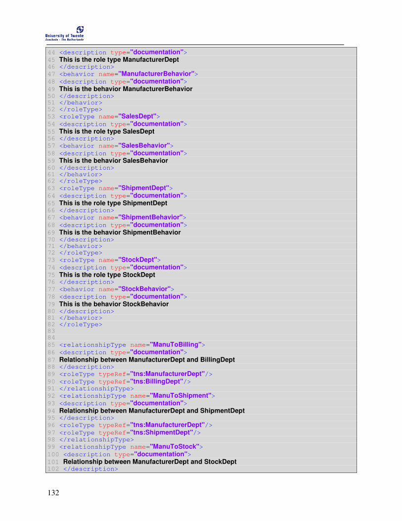
132
44 <description type="documentation"> 45 This is the role type ManufacturerDept 46 </description>
47 <behavior name="ManufacturerBehavior"> 48 <description type="documentation"> 49 This is the behavior ManufacturerBehavior 50 </description> 51 </behavior> 52 </roleType>
53 <roleType name="SalesDept"> 54 <description type="documentation"> 55 This is the role type SalesDept 56 </description>
57 <behavior name="SalesBehavior"> 58 <description type="documentation"> 59 This is the behavior SalesBehavior 60 </description> 61 </behavior> 62 </roleType>
63 <roleType name="ShipmentDept"> 64 <description type="documentation"> 65 This is the role type ShipmentDept 66 </description>
67 <behavior name="ShipmentBehavior"> 68 <description type="documentation"> 69 This is the behavior ShipmentBehavior 70 </description> 71 </behavior> 72 </roleType>
73 <roleType name="StockDept"> 74 <description type="documentation"> 75 This is the role type StockDept 76 </description>
77 <behavior name="StockBehavior"> 78 <description type="documentation"> 79 This is the behavior StockBehavior 80 </description> 81 </behavior> 82 </roleType> 83 84
85 <relationshipType name="ManuToBilling"> 86 <description type="documentation"> 87 Relationship between ManufacturerDept and BillingDept 88 </description>
89 <roleType typeRef="tns:ManufacturerDept"/> 90 <roleType typeRef="tns:BillingDept"/> 91 </relationshipType>
92 <relationshipType name="ManuToShipment"> 93 <description type="documentation"> 94 Relationship between ManufacturerDept and ShipmentDept 95 </description>
96 <roleType typeRef="tns:ManufacturerDept"/> 97 <roleType typeRef="tns:ShipmentDept"/> 98 </relationshipType>
99 <relationshipType name="ManuToStock"> 100 <description type="documentation"> 101 Relationship between ManufacturerDept and StockDept 102 </description>

133
103 <roleType typeRef="tns:ManufacturerDept"/> 104 <roleType typeRef="tns:StockDept"/> 105 </relationshipType>
106 <relationshipType name="SalesToManu"> 107 <description type="documentation"> 108 Relationship between SalesDept and ManufacturerDept 109 </description>
110 <roleType typeRef="tns:SalesDept"/> 111 <roleType typeRef="tns:ManufacturerDept"/> 112 </relationshipType> 113 114
115 <participantType name="BillingDeptParticipant"> 116 <description type="documentation"> 117 This is the participant type BillingDeptParticipant 118 </description>
119 <roleType typeRef="tns:BillingDept"/> 120 </participantType>
121 <participantType name="ManufacturerDeptParticipant"> 122 <description type="documentation"> 123 This is the participant type ManufacturerDeptParticipant 124 </description>
125 <roleType typeRef="tns:ManufacturerDept"/> 126 </participantType>
127 <participantType name="SalesDeptParticipant"> 128 <description type="documentation"> 129 This is the participant type SalesDeptParticipant 130 </description>
131 <roleType typeRef="tns:SalesDept"/> 132 </participantType>
133 <participantType name="ShipmentDeptParticipant"> 134 <description type="documentation"> 135 This is the participant type ShipmentDeptParticipant 136 </description>
137 <roleType typeRef="tns:ShipmentDept"/> 138 </participantType>
139 <participantType name="StockDeptParticipant"> 140 <description type="documentation"> 141 This is the participant type StockDeptParticipant 142 </description>
143 <roleType typeRef="tns:StockDept"/> 144 </participantType> 145
146 <channelType name="BillingChannel"> 147 <description type="documentation"> 148 This is the channel type BillingChannel 149 </description>
150 <roleType behavior="BillingBehavior" typeRef="tns:BillingDept"/> 151 <reference>
152 <token name="tns:BillingRef"/> 153 </reference> 154 </channelType> 155
156 <channelType name="ManufacturerChannel"> 157 <description type="documentation"> 158 This is the channel type ManufacturerChannel 159 </description>
160 <roleType behavior="ManufacturerBehavior" typeRef="tns:ManufacturerDept"/> 161 <reference>

134
162 <token name="tns:ManuRef"/> 163 </reference> 164 </channelType>
165 <channelType name="SalesChannel"> 166 <description type="documentation"> 167 This is the channel type SalesChannel 168 </description>
169 <roleType behavior="SalesBehavior" typeRef="tns:SalesDept"/> 170 <reference>
171 <token name="tns:SalesRef"/> 172 </reference> 173 </channelType>
174 <channelType name="ShipmentChannel"> 175 <description type="documentation"> 176 This is the channel type ShipmentChannel 177 </description>
178 <roleType behavior="ShipmentBehavior" typeRef="tns:ShipmentDept"/> 179 <reference>
180 <token name="tns:ShipmentRef"/> 181 </reference> 182 </channelType>
183 <channelType name="StockChannel"> 184 <description type="documentation"> 185 This is the channel type StockChannel 186 </description>
187 <roleType behavior="StockBehavior" typeRef="tns:StockDept"/> 188 <reference>
189 <token name="tns:StockRef"/> 190 </reference> 191 </channelType>
194 <choreography name="purchaseOrderProcess" root="true"> 195 <description type="documentation"> 196 Choreography flow for the purchaseOrder process 197 </description>
198 <relationship type="tns:ManuToBilling"/> 199 <relationship type="tns:ManuToShipment"/> 200 <relationship type="tns:ManuToStock"/> 201 <relationship type="tns:SalesToManu"/> 202 <variableDefinitions>
203 <variable channelType="tns:BillingChannel" name="BillingChannelInstance" roleTypes="tns:BillingDept tns:ManufacturerDept"> 204 <description type="documentation"> 205 This is the variable BillingChannelInstance 206 </description> 207 </variable>
208 <variable informationType="tns:BillingInfo" name="BillingInfo" roleTypes= "tns:BillingDept tns:ManufacturerDept"> 209 <description type="documentation"> 210 This is the variable BillingInfo 211 </description> 212 </variable>
213 <variable informationType="tns:BillingInfoResponse" name= "BillingInfoResponse" roleTypes="tns:BillingDept tns:ManufacturerDept"> 214 <description type="documentation"> 215 This is the variable BillingInfoResponse 216 </description> 217 </variable>
218 <variable informationType="tns:GoodStockInfo" name="GoodStockInfo" roleTypes
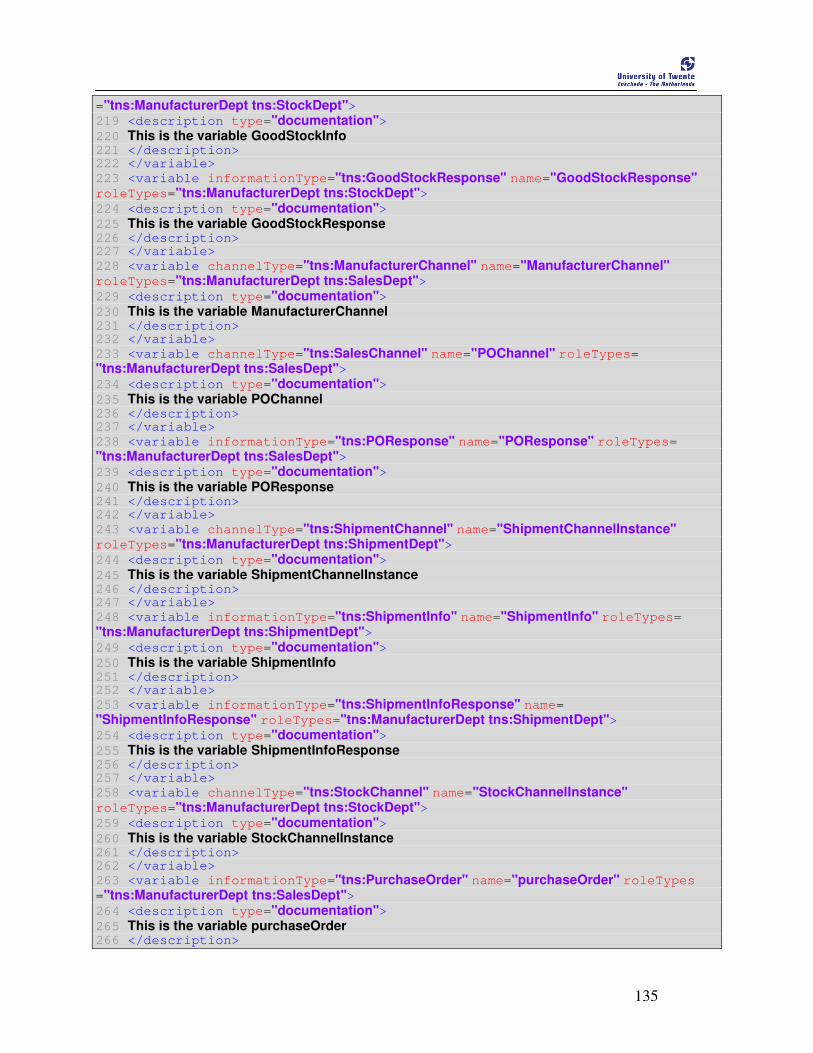
135
="tns:ManufacturerDept tns:StockDept"> 219 <description type="documentation"> 220 This is the variable GoodStockInfo 221 </description> 222 </variable>
223 <variable informationType="tns:GoodStockResponse" name="GoodStockResponse" roleTypes="tns:ManufacturerDept tns:StockDept"> 224 <description type="documentation"> 225 This is the variable GoodStockResponse 226 </description> 227 </variable>
228 <variable channelType="tns:ManufacturerChannel" name="ManufacturerChannel" roleTypes="tns:ManufacturerDept tns:SalesDept"> 229 <description type="documentation"> 230 This is the variable ManufacturerChannel 231 </description> 232 </variable>
233 <variable channelType="tns:SalesChannel" name="POChannel" roleTypes= "tns:ManufacturerDept tns:SalesDept"> 234 <description type="documentation"> 235 This is the variable POChannel 236 </description> 237 </variable>
238 <variable informationType="tns:POResponse" name="POResponse" roleTypes= "tns:ManufacturerDept tns:SalesDept"> 239 <description type="documentation"> 240 This is the variable POResponse 241 </description> 242 </variable>
243 <variable channelType="tns:ShipmentChannel" name="ShipmentChannelInstance" roleTypes="tns:ManufacturerDept tns:ShipmentDept"> 244 <description type="documentation"> 245 This is the variable ShipmentChannelInstance 246 </description> 247 </variable>
248 <variable informationType="tns:ShipmentInfo" name="ShipmentInfo" roleTypes= "tns:ManufacturerDept tns:ShipmentDept"> 249 <description type="documentation"> 250 This is the variable ShipmentInfo 251 </description> 252 </variable>
253 <variable informationType="tns:ShipmentInfoResponse" name= "ShipmentInfoResponse" roleTypes="tns:ManufacturerDept tns:ShipmentDept"> 254 <description type="documentation"> 255 This is the variable ShipmentInfoResponse 256 </description> 257 </variable>
258 <variable channelType="tns:StockChannel" name="StockChannelInstance" roleTypes="tns:ManufacturerDept tns:StockDept"> 259 <description type="documentation"> 260 This is the variable StockChannelInstance 261 </description> 262 </variable>
263 <variable informationType="tns:PurchaseOrder" name="purchaseOrder" roleTypes ="tns:ManufacturerDept tns:SalesDept"> 264 <description type="documentation"> 265 This is the variable purchaseOrder 266 </description>
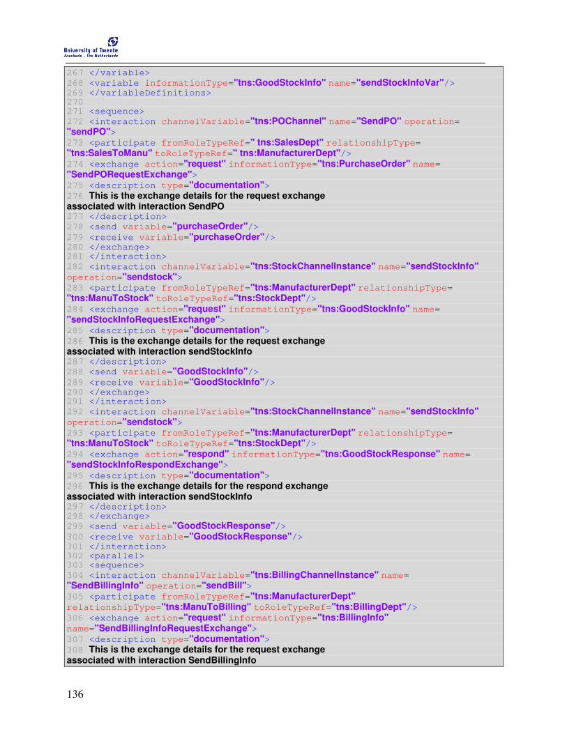
136
267 </variable>
268 <variable informationType="tns:GoodStockInfo" name="sendStockInfoVar"/> 269 </variableDefinitions> 270 271 <sequence>
272 <interaction channelVariable="tns:POChannel" name="SendPO" operation= "sendPO"> 273 <participate fromRoleTypeRef=" tns:SalesDept" relationshipType= "tns:SalesToManu" toRoleTypeRef=" tns:ManufacturerDept"/> 274 <exchange action="request" informationType="tns:PurchaseOrder" name= "SendPORequestExchange"> 275 <description type="documentation"> 276 This is the exchange details for the request exchange associated with interaction SendPO 277 </description>
278 <send variable="purchaseOrder"/> 279 <receive variable="purchaseOrder"/> 280 </exchange> 281 </interaction>
282 <interaction channelVariable="tns:StockChannelInstance" name="sendStockInfo" operation="sendstock"> 283 <participate fromRoleTypeRef="tns:ManufacturerDept" relationshipType= "tns:ManuToStock" toRoleTypeRef="tns:StockDept"/> 284 <exchange action="request" informationType="tns:GoodStockInfo" name= "sendStockInfoRequestExchange"> 285 <description type="documentation"> 286 This is the exchange details for the request exchange associated with interaction sendStockInfo 287 </description>
288 <send variable="GoodStockInfo"/> 289 <receive variable="GoodStockInfo"/> 290 </exchange> 291 </interaction>
292 <interaction channelVariable="tns:StockChannelInstance" name="sendStockInfo" operation="sendstock"> 293 <participate fromRoleTypeRef="tns:ManufacturerDept" relationshipType= "tns:ManuToStock" toRoleTypeRef="tns:StockDept"/> 294 <exchange action="respond" informationType="tns:GoodStockResponse" name= "sendStockInfoRespondExchange"> 295 <description type="documentation"> 296 This is the exchange details for the respond exchange associated with interaction sendStockInfo 297 </description> 298 </exchange>
299 <send variable="GoodStockResponse"/> 300 <receive variable="GoodStockResponse"/> 301 </interaction> 302 <parallel> 303 <sequence>
304 <interaction channelVariable="tns:BillingChannelInstance" name= "SendBillingInfo" operation="sendBill"> 305 <participate fromRoleTypeRef="tns:ManufacturerDept" relationshipType="tns:ManuToBilling" toRoleTypeRef="tns:BillingDept"/> 306 <exchange action="request" informationType="tns:BillingInfo" name="SendBillingInfoRequestExchange"> 307 <description type="documentation"> 308 This is the exchange details for the request exchange associated with interaction SendBillingInfo
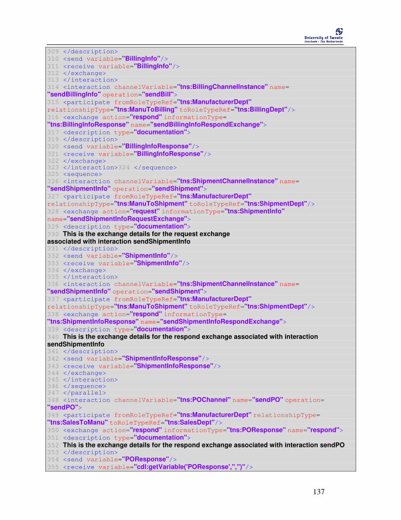
137
309 </description>
310 <send variable="BillingInfo"/> 311 <receive variable="BillingInfo"/> 312 </exchange> 313 </interaction>
314 <interaction channelVariable="tns:BillingChannelInstance" name= "sendBillingInfo" operation="sendBill"> 315 <participate fromRoleTypeRef="tns:ManufacturerDept" relationshipType="tns:ManuToBilling" toRoleTypeRef="tns:BillingDept"/> 316 <exchange action="respond" informationType= "tns:BillingInfoResponse" name="sendBillingInfoRespondExchange"> 317 <description type="documentation"> 319 </description>
320 <send variable="BillingInfoResponse"/> 321 <receive variable="BillingInfoResponse"/> 322 </exchange> 323 </interaction>324 </sequence> 325 <sequence>
326 <interaction channelVariable="tns:ShipmentChannelInstance" name= "sendShipmentInfo" operation="sendShipment"> 327 <participate fromRoleTypeRef="tns:ManufacturerDept" relationshipType="tns:ManuToShipment" toRoleTypeRef="tns:ShipmentDept"/> 328 <exchange action="request" informationType="tns:ShipmentInfo" name="sendShipmentInfoRequestExchange"> 329 <description type="documentation"> 330 This is the exchange details for the request exchange associated with interaction sendShipmentInfo 331 </description>
332 <send variable="ShipmentInfo"/> 333 <receive variable="ShipmentInfo"/> 334 </exchange> 335 </interaction>
336 <interaction channelVariable="tns:ShipmentChannelInstance" name= "sendShipmentInfo" operation="sendShipment"> 337 <participate fromRoleTypeRef="tns:ManufacturerDept" relationshipType="tns:ManuToShipment" toRoleTypeRef="tns:ShipmentDept"/> 338 <exchange action="respond" informationType= "tns:ShipmentInfoResponse" name="sendShipmentInfoRespondExchange"> 339 <description type="documentation"> 340 This is the exchange details for the respond exchange associated with interaction sendShipmentInfo 341 </description>
342 <send variable="ShipmentInfoResponse"/> 343 <receive variable="ShipmentInfoResponse"/> 344 </exchange> 345 </interaction> 346 </sequence> 347 </parallel>
348 <interaction channelVariable="tns:POChannel" name="sendPO" operation= "sendPO"> 349 <participate fromRoleTypeRef="tns:ManufacturerDept" relationshipType= "tns:SalesToManu" toRoleTypeRef="tns:SalesDept"/> 350 <exchange action="respond" informationType="tns:POResponse" name="respond"> 351 <description type="documentation"> 352 This is the exchange details for the respond exchange associated with interaction sendPO 353 </description>
354 <send variable="POResponse"/> 355 <receive variable="cdl:getVariable('POResponse','','')"/>

138
356 </exchange> 357 </interaction> 358 </sequence> 359 </choreography> 360 </package>

139
Appendix E
CDL Specification of BTO application scenario Filename: BuildToOrder.cdl
1 <?xml version="1.0" encoding="UTF-8"?> 2
3 <package xmlns="http://www.w3.org/2005/10/cdl" xmlns:b2o= "http://example.org/build2order" xmlns:cdl="http://www.w3.org/2005/10/cdl" xmlns:tns= "http://example.org/build2order" xmlns:xsd="http://www.w3.org/2001/XMLSchema" xmlns:qosp ="http://stud3.tuwien.ac.at/~e9751151/ws/2006/12/qos/policy" author="Christian Enzi" name="BuildToOrderCDL" targetNamespace="http://example.org/build2order" version="x"> 4 <description type="documentation">A Sample BuildToOrder Choreography!!!</description> 5 <informationType name="BooleanType" type="xsd:boolean"/> 6 <informationType name="StringType" type="xsd:string"/> 7 <informationType name="PurchaseOrder" type="b2o:PurchaseOrder"/> 8 <informationType name="HardwareOrder" type="b2o:HardwareOrder"/> 9 <informationType name="HardwareOrderResponse" type="b2o:HardwareOrderResponse"/> 10 <informationType name="PurchaseOrderResponse" type="b2o:PurchaseOrderResponse"/> 11 <informationType name="QuoteRequest" type="b2o:QuoteRequest"/> 12 <informationType name="QuoteResponse" type="b2o:QuoteResponse"/> 13 <informationType name="QuoteUpdate" type="b2o:QuoteUpdate"/> 14 <informationType name="IntegerType" type="xsd:int"/> 15 <informationType name="QuoteAccept" type="b2o:QuoteAccept"/> 16 <token informationType="tns:StringType" name="CustRef"/> 17 <token informationType="tns:StringType" name="ManRef"/> 18 <token informationType="tns:StringType" name="SupCPURef"/> 19 <token informationType="tns:StringType" name="SupHDRef"/> 20 <token informationType="tns:StringType" name="SupMBRef"/> 21 <roleType name="CustRoleType"> 22 <behavior interface="b2o:custInterface" name="CustBehaviour"/> 23 </roleType>
24 <roleType name="ManRoleType"> 25 <behavior interface="b2o:manInterface" name="ManBehaviour"> 26 </behavior> 27 </roleType>
28 <roleType name="SupCPURoleType"> 29 <behavior interface="b2o:supCPUInterface" name="SupCPUBehavior"> 30 </behavior> 31 </roleType>
32 <roleType name="InitRoleType"> 33 <behavior interface="b2o:initInterface" name="InitBehaviour"/> 34 </roleType>
35 <roleType name="SupMBRoleType"> 36 <behavior interface="b2o:supMBInterface" name="SupMBBehaviour"> 37 </behavior> 38 </roleType>
39 <roleType name="SupHDRoleType"> 40 <behavior interface="b2o:supHDInterface" name="SupHDBehaviour"> 41 </behavior>
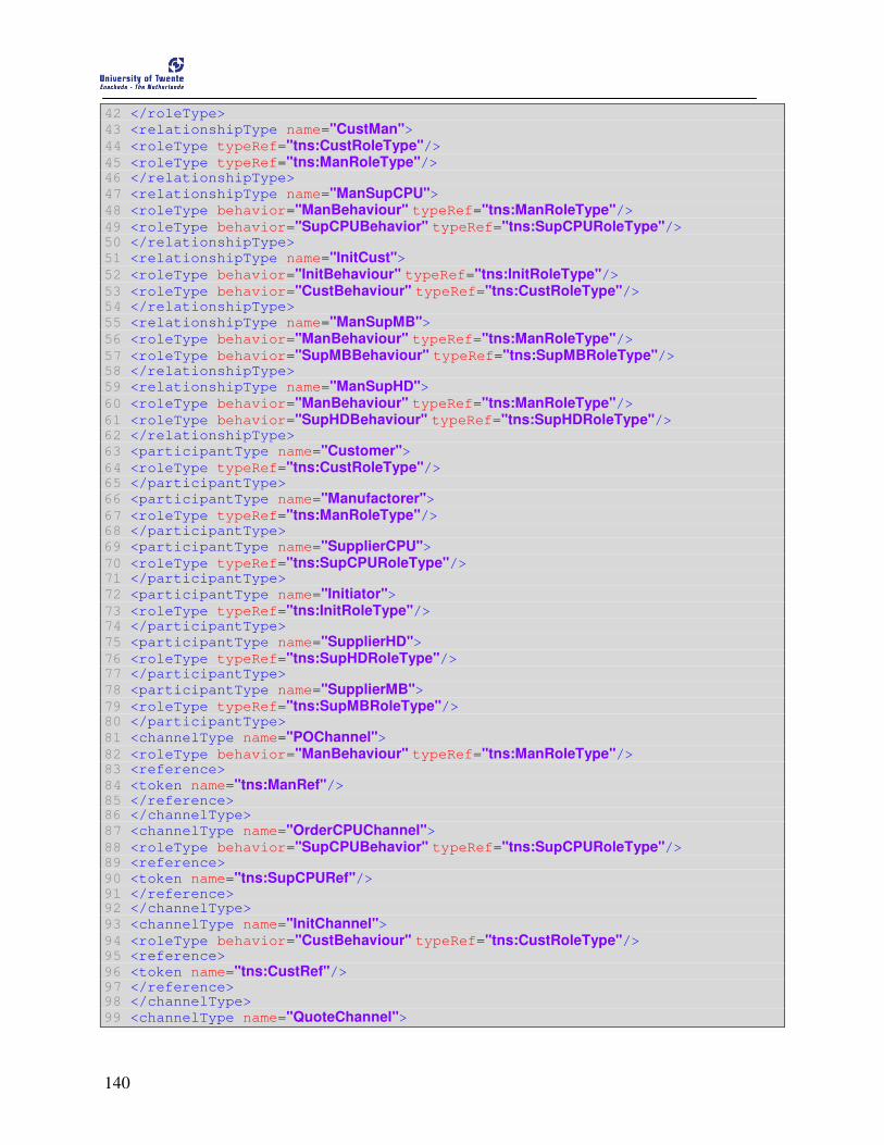
140
42 </roleType>
43 <relationshipType name="CustMan"> 44 <roleType typeRef="tns:CustRoleType"/> 45 <roleType typeRef="tns:ManRoleType"/> 46 </relationshipType>
47 <relationshipType name="ManSupCPU"> 48 <roleType behavior="ManBehaviour" typeRef="tns:ManRoleType"/> 49 <roleType behavior="SupCPUBehavior" typeRef="tns:SupCPURoleType"/> 50 </relationshipType>
51 <relationshipType name="InitCust"> 52 <roleType behavior="InitBehaviour" typeRef="tns:InitRoleType"/> 53 <roleType behavior="CustBehaviour" typeRef="tns:CustRoleType"/> 54 </relationshipType>
55 <relationshipType name="ManSupMB"> 56 <roleType behavior="ManBehaviour" typeRef="tns:ManRoleType"/> 57 <roleType behavior="SupMBBehaviour" typeRef="tns:SupMBRoleType"/> 58 </relationshipType>
59 <relationshipType name="ManSupHD"> 60 <roleType behavior="ManBehaviour" typeRef="tns:ManRoleType"/> 61 <roleType behavior="SupHDBehaviour" typeRef="tns:SupHDRoleType"/> 62 </relationshipType>
63 <participantType name="Customer"> 64 <roleType typeRef="tns:CustRoleType"/> 65 </participantType>
66 <participantType name="Manufactorer"> 67 <roleType typeRef="tns:ManRoleType"/> 68 </participantType>
69 <participantType name="SupplierCPU"> 70 <roleType typeRef="tns:SupCPURoleType"/> 71 </participantType>
72 <participantType name="Initiator"> 73 <roleType typeRef="tns:InitRoleType"/> 74 </participantType>
75 <participantType name="SupplierHD"> 76 <roleType typeRef="tns:SupHDRoleType"/> 77 </participantType>
78 <participantType name="SupplierMB"> 79 <roleType typeRef="tns:SupMBRoleType"/> 80 </participantType>
81 <channelType name="POChannel"> 82 <roleType behavior="ManBehaviour" typeRef="tns:ManRoleType"/> 83 <reference>
84 <token name="tns:ManRef"/> 85 </reference> 86 </channelType>
87 <channelType name="OrderCPUChannel"> 88 <roleType behavior="SupCPUBehavior" typeRef="tns:SupCPURoleType"/> 89 <reference>
90 <token name="tns:SupCPURef"/> 91 </reference> 92 </channelType>
93 <channelType name="InitChannel"> 94 <roleType behavior="CustBehaviour" typeRef="tns:CustRoleType"/> 95 <reference>
96 <token name="tns:CustRef"/> 97 </reference> 98 </channelType>
99 <channelType name="QuoteChannel">

141
100 <roleType behavior="ManBehaviour" typeRef="tns:ManRoleType"/> 101 <reference>
102 <token name="tns:ManRef"/> 103 </reference> 104 </channelType>
105 <channelType name="OrderMBChannel"> 106 <roleType behavior="SupMBBehaviour" typeRef="tns:SupMBRoleType"/> 107 <reference>
108 <token name="tns:SupMBRef"/> 109 </reference> 110 </channelType>
111 <channelType name="OrderHDChannel"> 112 <roleType behavior="SupHDBehaviour" typeRef="tns:SupHDRoleType"/> 113 <reference>
114 <token name="tns:SupHDRef"/> 115 </reference> 116 </channelType>
117 <channelType name="InfoChannelReq2Resp"> 118 <roleType behavior="ManBehaviour" typeRef="tns:ManRoleType"/> 119 <reference>
120 <token name="tns:ManRef"/> 121 </reference> 122 </channelType>
123 <choreography name="BuildToOrderChoreography" root="true"> 124 <relationship type="tns:CustMan"/> 125 <relationship type="tns:ManSupCPU"/> 126 <relationship type="tns:InitCust"/> 127 <relationship type="tns:ManSupMB"/> 128 <relationship type="tns:ManSupHD"/> 129 <variableDefinitions>
130 <variable channelType="tns:POChannel" name="POChannelInstance" roleTypes= "tns:CustRoleType tns:ManRoleType"/> 131 <variable informationType="tns:PurchaseOrder" name="PurchaseOrder" roleTypes= "tns:CustRoleType tns:ManRoleType"/> 132 <variable informationType="tns:PurchaseOrderResponse" name="PurchaseOrderResponse" roleTypes="tns:CustRoleType tns:ManRoleType tns:InitRoleType"/> 133 <variable informationType="tns:IntegerType" name="CPUnotInStock" roleTypes= "tns:ManRoleType" silent="true"/> 134 <variable channelType="tns:OrderCPUChannel" name="OrderCPUChannelInstance" roleTypes="tns:ManRoleType tns:SupCPURoleType"/> 135 <variable informationType="tns:HardwareOrder" name="HardwareOrderCPU" roleTypes=
"tns:ManRoleType tns:SupCPURoleType"/> 136 <variable informationType="tns:HardwareOrderResponse" name= "HardwareOrderCPUResponse" roleTypes="tns:ManRoleType tns:SupCPURoleType"/> 137 <variable channelType="tns:InitChannel" name="InitChannelInstance" roleTypes= "tns:CustRoleType tns:InitRoleType"/> 138 <variable channelType="tns:QuoteChannel" name="QuoteChannelInstance" roleTypes= "tns:CustRoleType tns:ManRoleType"/> 139 <variable informationType="tns:QuoteAccept" name="QuoteAccept" roleTypes= "tns:CustRoleType tns:ManRoleType"/> 140 <variable informationType="tns:QuoteRequest" name="QuoteRequest" roleTypes= "tns:CustRoleType tns:ManRoleType tns:InitRoleType"/> 141 <variable informationType="tns:QuoteResponse" name="QuoteResponse" roleTypes= "tns:CustRoleType tns:ManRoleType"/> 142 <variable informationType="tns:QuoteUpdate" name="QuoteUpdate" roleTypes=

142
"tns:CustRoleType tns:ManRoleType"/>
143 <variable channelType="tns:OrderMBChannel" name="OrderMBChannelInstance" roleTypes
="tns:ManRoleType tns:SupMBRoleType"/> 144 <variable channelType="tns:OrderHDChannel" name="OrderHDChannelInstance" roleTypes
="tns:ManRoleType tns:SupHDRoleType"/> 145 <variable informationType="tns:IntegerType" name="MBnotInStock" roleTypes= "tns:ManRoleType" silent="true"/> 146 <variable informationType="tns:IntegerType" name="HDnotInStock" roleTypes= "tns:ManRoleType" silent="true"/> 147 <variable informationType="tns:HardwareOrder" name="HardwareOrderMB" roleTypes=
"tns:ManRoleType tns:SupMBRoleType"/> 148 <variable informationType="tns:HardwareOrderResponse" name= "HardwareOrderMBResponse" roleTypes="tns:ManRoleType tns:SupMBRoleType"/> 149 <variable informationType="tns:HardwareOrder" name="HardwareOrderHD" roleTypes=
"tns:ManRoleType tns:SupHDRoleType"/> 150 <variable informationType="tns:HardwareOrderResponse" name= "HardwareOrderHDResponse" roleTypes="tns:ManRoleType tns:SupHDRoleType"/> 151 <variable channelType="tns:InfoChannelReq2Resp" name="InfoChannelReq2RespInstance" roleTypes="tns:CustRoleType tns:ManRoleType"/> 152 </variableDefinitions> 153 <sequence>
154 <interaction channelVariable="tns:InitChannelInstance" initiate="true" name= "Initialize" operation="initialize"> 155 <description type="documentation">Initializes Choreography by invoking Customer BPEL Process</description> 156 <participate fromRoleTypeRef="tns:InitRoleType" relationshipType="tns:InitCust" toRoleTypeRef="tns:CustRoleType"/> 157 <exchange action="request" informationType="tns:QuoteRequest" name="request"> 158 <send variable="cdl:getVariable('QuoteRequest','','')"/> 159 <receive variable="cdl:getVariable('QuoteRequest','','')"/> 160 </exchange> 161 </interaction> 162 <sequence> 163 <sequence>
164 <description type="documentation">ProcessQuote</description> 165 <interaction channelVariable="tns:QuoteChannelInstance" name="RequestForQuote" operation="requestForQuote"> 166 <participate fromRoleTypeRef="tns:CustRoleType" relationshipType= "tns:CustMan" toRoleTypeRef="tns:ManRoleType"/> 167 <exchange action="request" informationType="tns:QuoteRequest" name="request"> 168 <send variable="cdl:getVariable('QuoteRequest','','')"/> 169 <receive variable="cdl:getVariable('QuoteRequest','','')"/> 170 </exchange> 171 </interaction>
172 <silentAction name="Manufactorer_ProcessRequest" roleType="tns:ManRoleType"> 173 <description type="documentation">[Manufactorer]: Process Request </description> 174 </silentAction>
175 <interaction channelVariable="tns:QuoteChannelInstance" name="RequestForQuote" operation="requestForQuote"> 176 <participate fromRoleTypeRef="tns:CustRoleType" relationshipType= "tns:CustMan" toRoleTypeRef="tns:ManRoleType"/>
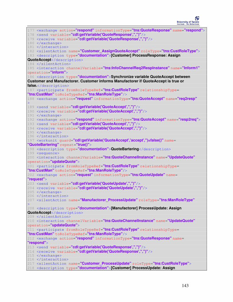
143
177 <exchange action="respond" informationType="tns:QuoteResponse" name="respond"> 178 <send variable="cdl:getVariable('QuoteResponse','','')"/> 179 <receive variable="cdl:getVariable('QuoteResponse','','')"/> 180 </exchange> 181 </interaction>
182 <silentAction name="Customer_AssignQuoteAccept" roleType="tns:CustRoleType"> 183 <description type="documentation">[Customer] ProcessResponse: Assign QuoteAccept</description> 184 </silentAction>
185 <interaction channelVariable="tns:InfoChannelReq2RespInstance" name="Inform1" operation="inform"> 186 <description type="documentation">Synchronize variable QuoteAccept between Customer and Manufactorer. Customer informs Manufactorer if QuoteAccept is true or false.</description> 187 <participate fromRoleTypeRef="tns:CustRoleType" relationshipType= "tns:CustMan" toRoleTypeRef="tns:ManRoleType"/> 188 <exchange action="request" informationType="tns:QuoteAccept" name="req2resp" >
189 <send variable="cdl:getVariable('QuoteAccept','','')"/> 190 <receive variable="cdl:getVariable('QuoteAccept','','')"/> 191 </exchange>
192 <exchange action="respond" informationType="tns:QuoteAccept" name="resp2req"> 193 <send variable="cdl:getVariable('QuoteAccept','','')"/> 194 <receive variable="cdl:getVariable('QuoteAccept','','')"/> 195 </exchange> 196 </interaction>
197 <workunit guard="cdl:getVariable('QuoteAccept','accept','')=false()" name= "QuoteBartering" repeat="true()"> 198 <description type="documentation">QuoteBartering</description> 199 <sequence>
200 <interaction channelVariable="tns:QuoteChannelInstance" name="UpdateQuote" operation="updateQuote"> 201 <participate fromRoleTypeRef="tns:CustRoleType" relationshipType= "tns:CustMan" toRoleTypeRef="tns:ManRoleType"/> 202 <exchange action="request" informationType="tns:QuoteUpdate" name= "request"> 203 <send variable="cdl:getVariable('QuoteUpdate','','')"/> 204 <receive variable="cdl:getVariable('QuoteUpdate','','')"/> 205 </exchange> 206 </interaction>
207 <silentAction name="Manufactorer_ProcessUpdate" roleType="tns:ManRoleType" >
208 <description type="documentation">[Manufactorer] ProcessUpdate: Assign QuoteAccept</description> 209 </silentAction>
210 <interaction channelVariable="tns:QuoteChannelInstance" name="UpdateQuote" operation="updateQuote"> 211 <participate fromRoleTypeRef="tns:CustRoleType" relationshipType= "tns:CustMan" toRoleTypeRef="tns:ManRoleType"/> 212 <exchange action="respond" informationType="tns:QuoteResponse" name= "respond"> 213 <send variable="cdl:getVariable('QuoteResponse','','')"/>
214 <receive variable="cdl:getVariable('QuoteResponse','','')"/> 215 </exchange> 216 </interaction>
217 <silentAction name="Customer_ProcessUpdate" roleType="tns:CustRoleType"> 218 <description type="documentation">[Customer] ProcessUpdate: Assign
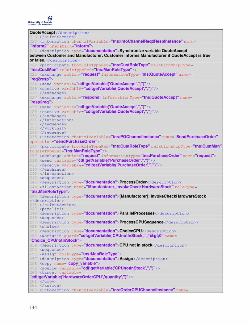
144
QuoteAccept</description> 219 </silentAction>
220 <interaction channelVariable="tns:InfoChannelReq2RespInstance" name= "Inform2" operation="inform"> 221 <description type="documentation">Synchronize variable QuoteAccept between Customer and Manufactorer. Customer informs Manufactorer if QuoteAccept is true or false.</description> 222 <participate fromRoleTypeRef="tns:CustRoleType" relationshipType= "tns:CustMan" toRoleTypeRef="tns:ManRoleType"/> 223 <exchange action="request" informationType="tns:QuoteAccept" name= "req2resp"> 224 <send variable="cdl:getVariable('QuoteAccept','','')"/> 225 <receive variable="cdl:getVariable('QuoteAccept','','')"/> 226 </exchange>
227 <exchange action="respond" informationType="tns:QuoteAccept" name= "resp2req"> 228 <send variable="cdl:getVariable('QuoteAccept','','')"/> 229 <receive variable="cdl:getVariable('QuoteAccept','','')"/> 230 </exchange> 231 </interaction> 232 </sequence> 233 </workunit> 234 </sequence>
235 <interaction channelVariable="tns:POChannelInstance" name="SendPurchaseOrder" operation="sendPurchaseOrder"> 236 <participate fromRoleTypeRef="tns:CustRoleType" relationshipType="tns:CustMan" toRoleTypeRef="tns:ManRoleType"/> 237 <exchange action="request" informationType="tns:PurchaseOrder" name="request"> 238 <send variable="cdl:getVariable('PurchaseOrder','','')"/> 239 <receive variable="cdl:getVariable('PurchaseOrder','','')"/> 240 </exchange> 241 </interaction> 242 <sequence>
243 <description type="documentation">ProcessOrder</description> 244 <silentAction name="Manufactorer_InvokeCheckHardwareStock" roleType= "tns:ManRoleType"> 245 <description type="documentation">[Manufactorer]: InvokeCheckHardwareStock </description> 246 </silentAction> 247 <parallel>
248 <description type="documentation">ParallelProcesses</description> 249 <sequence>
250 <description type="documentation">ProcessCPUSequence</description> 251 <choice>
252 <description type="documentation">ChoiceCPU</description> 253 <workunit guard="cdl:getVariable('CPUnotInStock','','')>0" name= "Choice_CPUnotInStock"> 254 <description type="documentation">CPU not in stock</description>
255 <sequence>
256 <assign roleType="tns:ManRoleType"> 257 <description type="documentation">Assign</description> 258 <copy name="copy_variable"> 259 <source variable="cdl:getVariable('CPUnotInStock','','')"/> 260 <target variable=
"cdl:getVariable('HardwareOrderCPU','quantity','')"/> 261 </copy> 262 </assign>
263 <interaction channelVariable="tns:OrderCPUChannelInstance" name=
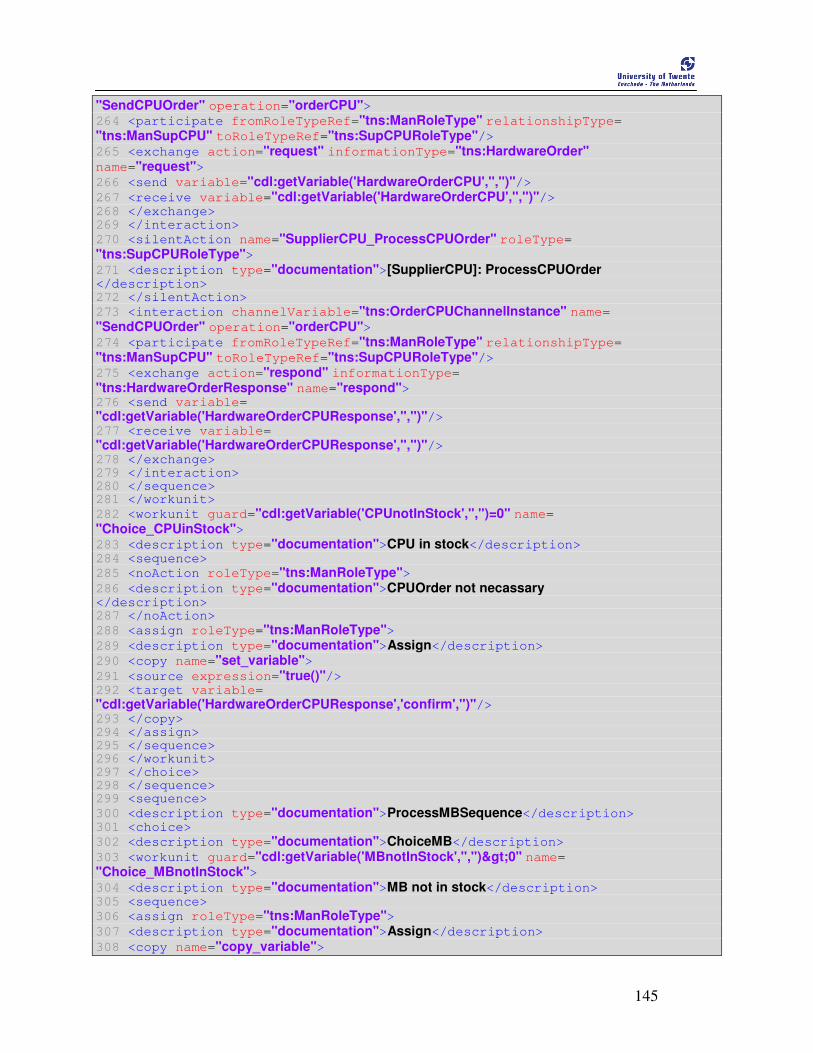
145
"SendCPUOrder" operation="orderCPU"> 264 <participate fromRoleTypeRef="tns:ManRoleType" relationshipType= "tns:ManSupCPU" toRoleTypeRef="tns:SupCPURoleType"/> 265 <exchange action="request" informationType="tns:HardwareOrder" name="request"> 266 <send variable="cdl:getVariable('HardwareOrderCPU','','')"/> 267 <receive variable="cdl:getVariable('HardwareOrderCPU','','')"/> 268 </exchange> 269 </interaction>
270 <silentAction name="SupplierCPU_ProcessCPUOrder" roleType= "tns:SupCPURoleType"> 271 <description type="documentation">[SupplierCPU]: ProcessCPUOrder </description> 272 </silentAction>
273 <interaction channelVariable="tns:OrderCPUChannelInstance" name= "SendCPUOrder" operation="orderCPU"> 274 <participate fromRoleTypeRef="tns:ManRoleType" relationshipType= "tns:ManSupCPU" toRoleTypeRef="tns:SupCPURoleType"/> 275 <exchange action="respond" informationType= "tns:HardwareOrderResponse" name="respond"> 276 <send variable=
"cdl:getVariable('HardwareOrderCPUResponse','','')"/> 277 <receive variable=
"cdl:getVariable('HardwareOrderCPUResponse','','')"/> 278 </exchange> 279 </interaction> 280 </sequence> 281 </workunit>
282 <workunit guard="cdl:getVariable('CPUnotInStock','','')=0" name= "Choice_CPUinStock"> 283 <description type="documentation">CPU in stock</description> 284 <sequence>
285 <noAction roleType="tns:ManRoleType"> 286 <description type="documentation">CPUOrder not necassary </description> 287 </noAction>
288 <assign roleType="tns:ManRoleType"> 289 <description type="documentation">Assign</description> 290 <copy name="set_variable"> 291 <source expression="true()"/> 292 <target variable=
"cdl:getVariable('HardwareOrderCPUResponse','confirm','')"/> 293 </copy>
294 </assign> 295 </sequence> 296 </workunit> 297 </choice> 298 </sequence> 299 <sequence>
300 <description type="documentation">ProcessMBSequence</description> 301 <choice>
302 <description type="documentation">ChoiceMB</description> 303 <workunit guard="cdl:getVariable('MBnotInStock','','')>0" name= "Choice_MBnotInStock"> 304 <description type="documentation">MB not in stock</description> 305 <sequence>
306 <assign roleType="tns:ManRoleType"> 307 <description type="documentation">Assign</description> 308 <copy name="copy_variable">
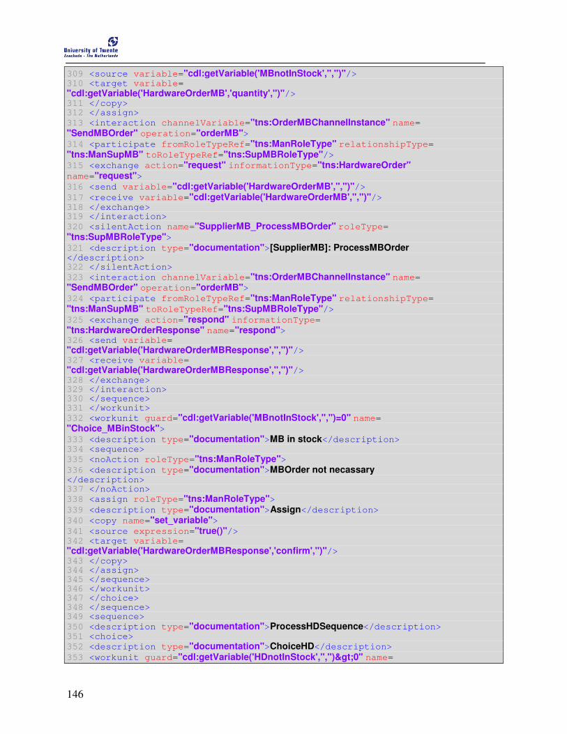
146
309 <source variable="cdl:getVariable('MBnotInStock','','')"/> 310 <target variable=
"cdl:getVariable('HardwareOrderMB','quantity','')"/> 311 </copy> 312 </assign>
313 <interaction channelVariable="tns:OrderMBChannelInstance" name= "SendMBOrder" operation="orderMB"> 314 <participate fromRoleTypeRef="tns:ManRoleType" relationshipType= "tns:ManSupMB" toRoleTypeRef="tns:SupMBRoleType"/> 315 <exchange action="request" informationType="tns:HardwareOrder" name="request"> 316 <send variable="cdl:getVariable('HardwareOrderMB','','')"/> 317 <receive variable="cdl:getVariable('HardwareOrderMB','','')"/> 318 </exchange> 319 </interaction>
320 <silentAction name="SupplierMB_ProcessMBOrder" roleType= "tns:SupMBRoleType"> 321 <description type="documentation">[SupplierMB]: ProcessMBOrder </description> 322 </silentAction>
323 <interaction channelVariable="tns:OrderMBChannelInstance" name= "SendMBOrder" operation="orderMB"> 324 <participate fromRoleTypeRef="tns:ManRoleType" relationshipType= "tns:ManSupMB" toRoleTypeRef="tns:SupMBRoleType"/> 325 <exchange action="respond" informationType= "tns:HardwareOrderResponse" name="respond"> 326 <send variable=
"cdl:getVariable('HardwareOrderMBResponse','','')"/> 327 <receive variable=
"cdl:getVariable('HardwareOrderMBResponse','','')"/> 328 </exchange> 329 </interaction> 330 </sequence> 331 </workunit>
332 <workunit guard="cdl:getVariable('MBnotInStock','','')=0" name= "Choice_MBinStock"> 333 <description type="documentation">MB in stock</description>
334 <sequence>
335 <noAction roleType="tns:ManRoleType"> 336 <description type="documentation">MBOrder not necassary </description> 337 </noAction>
338 <assign roleType="tns:ManRoleType"> 339 <description type="documentation">Assign</description> 340 <copy name="set_variable"> 341 <source expression="true()"/> 342 <target variable=
"cdl:getVariable('HardwareOrderMBResponse','confirm','')"/> 343 </copy> 344 </assign> 345 </sequence> 346 </workunit> 347 </choice> 348 </sequence> 349 <sequence>
350 <description type="documentation">ProcessHDSequence</description> 351 <choice>
352 <description type="documentation">ChoiceHD</description> 353 <workunit guard="cdl:getVariable('HDnotInStock','','')>0" name=

147
"Choice_HDnotInStock"> 354 <description type="documentation">HD not in stock</description> 355 <sequence>
356 <assign roleType="tns:ManRoleType"> 357 <description type="documentation">Assign</description> 358 <copy name="copy_variable"> 359 <source variable="cdl:getVariable('HDnotInStock','','')"/> 360 <target variable=
"cdl:getVariable('HardwareOrderHD','quantity','')"/> 361 </copy> 362 </assign>
363 <interaction channelVariable="tns:OrderHDChannelInstance" name= "SendHDOrder" operation="orderHD"> 364 <participate fromRoleTypeRef="tns:ManRoleType" relationshipType= "tns:ManSupHD" toRoleTypeRef="tns:SupHDRoleType"/> 365 <exchange action="request" informationType="tns:HardwareOrder" name="request"> 366 <send variable="cdl:getVariable('HardwareOrderHD','','')"/> 367 <receive variable="cdl:getVariable('HardwareOrderHD','','')"/> 368 </exchange> 369 </interaction>
370 <silentAction name="SupplierHD_ProcessHDOrder" roleType= "tns:SupHDRoleType"> 371 <description type="documentation">[SupplierHD]: ProcessHDOrder </description> 372 </silentAction>
373 <interaction channelVariable="tns:OrderHDChannelInstance" name= "SendHDOrder" operation="orderHD"> 374 <participate fromRoleTypeRef="tns:ManRoleType" relationshipType= "tns:ManSupHD" toRoleTypeRef="tns:SupHDRoleType"/> 375 <exchange action="respond" informationType=
"tns:HardwareOrderResponse" name="respond"> 376 <send variable=
"cdl:getVariable('HardwareOrderHDResponse','','')"/> 377 <receive variable=
"cdl:getVariable('HardwareOrderHDResponse','','')"/> 378 </exchange> 379 </interaction> 380 </sequence> 381 </workunit>
382 <workunit guard="cdl:getVariable('HDnotInStock','','')=0" name= "Choice_HDinStock"> 383 <description type="documentation">HD in stock</description> 384 <sequence>
385 <noAction roleType="tns:ManRoleType"> 386 <description type="documentation">HDOrder not necassary </description> 387 </noAction>
388 <assign roleType="tns:ManRoleType"> 389 <description type="documentation">Assign</description> 390 <copy name="set_variable"> 391 <source expression="true()"/> 392 <target variable=
"cdl:getVariable('HardwareOrderHDResponse','confirm','')"/> 393 </copy> 394 </assign> 395 </sequence> 396 </workunit> 397 </choice>

148
398 </sequence> 399 </parallel> 400 </sequence> 401 <sequence>
402 <description type="documentation">EvaluateOrder</description> 403 <choice>
404 <description type="documentation">ChoicePurchaseOrder</description> 405 <workunit guard=
"cdl:getVariable('HardwareOrderCPUResponse','confirm','')=true() and cdl:getVariable('HardwareOrderMBResponse','confirm','')=true() and cdl:getVariable('HardwareOrderHDResponse','confirm','')=true()" name="PO_success"> 406 <description type="documentation">Purchase Order successfully performed </description>
407 <assign roleType="tns:ManRoleType"> 408 <description type="documentation">Assign</description> 409 <copy name="set_variable"> 410 <source expression="true()"/> 411 <target variable=
"cdl:getVariable('PurchaseOrderResponse','confirm','')"/> 412 </copy> 413 </assign> 414 </workunit> 415 <workunit guard=
"cdl:getVariable('HardwareOrderCPUResponse','confirm','')=false() or cdl:getVariable('HardwareOrderMBResponse','confirm','')=false() or
cdl:getVariable('HardwareOrderHDResponse','confirm','')=false()" name="PO_failure"> 416 <description type="documentation">Purchase Order not successfully performed</description> 417 <assign roleType="tns:ManRoleType"> 418 <description type="documentation">Assign</description> 419 <copy name="set_variable"> 420 <source expression="false()"/> 421 <target variable=
"cdl:getVariable('PurchaseOrderResponse','confirm','')"/> 422 </copy> 423 </assign> 424 </workunit> 425 </choice> 426 </sequence>
427 <silentAction name="Manufactorer_AssignPurchaseOrderResponse" roleType= "tns:ManRoleType"> 428 <description type="documentation">[Manufactorer]: Assign PurchaseOrderResponse </description> 429 </silentAction>
430 <interaction channelVariable="tns:POChannelInstance" name="SendPurchaseOrder" operation="sendPurchaseOrder"> 431 <participate fromRoleTypeRef="tns:CustRoleType" relationshipType="tns:CustMan" toRoleTypeRef="tns:ManRoleType"/> 432 <exchange action="respond" informationType="tns:PurchaseOrderResponse" name= "respond"> 433 <send variable="cdl:getVariable('PurchaseOrderResponse','','')"/> 434 <receive variable="cdl:getVariable('PurchaseOrderResponse','','')"/> 435 </exchange> 436 </interaction> 437 </sequence>
438 <interaction channelVariable="tns:InitChannelInstance" name="Initialize" operation ="initialize"> 439 <description type="documentation">Sends result to client which has invoked the choreography</description>

149
440 <participate fromRoleTypeRef="tns:InitRoleType" relationshipType="tns:InitCust" toRoleTypeRef="tns:CustRoleType"/> 441 <exchange action="respond" informationType="tns:PurchaseOrderResponse" name= "respond"> 442 <send variable="cdl:getVariable('PurchaseOrderResponse','','')"/> 443 <receive variable="cdl:getVariable('PurchaseOrderResponse','','')"/> 444 </exchange> 445 </interaction> 446 </sequence> 447 </choreography> 448 </package>

150
151
Appendix F
Informal Syntax The specifications of the WSCDL 1.0 and the WSBPEL 2.0 use an informal syntax to describe the XML
grammar of WSDL and BPEL documents. The informal syntax is as follows.
• The syntax appears as an XML instance, but the values indicate the data types instead of values.
• Characters are appended to elements and attributes as follows: “?” (0 or 1), “*” (0 or more), “+”
(1 or more). The characters “[” and “]” are used to indicate that contained items are to be
treated as a group with respect to the “?”, “*”, or “+” characters. We call them occurence
indicators.
• Elements names ending in “...” (such as <element ... /> or <element ... >) indicate that elements
or attributes irrelevant to the context are being omitted. We call them irrelevance indicators.
• Elements and attributes separated by “|” and grouped by “(” and “)” are meant to be syntactic
alternatives.
• The XML namespace prefixes are used to indicate the namespace of the element being defined.