MODEL, DESIGN AND IMPLEMENTATION OF LCC CONVERTER …
9
Eletrôn. Potên., Joinville, v. 24, n. 2, p. 246-254, abr./jun. 2019 246 Model, Design and Implementation of LCC Converter for Power Generation and Dis- tributed Generation Renan F. Bastos, André L. A. Dias, Ricardo Q. Machado MODEL, DESIGN AND IMPLEMENTATION OF LCC CONVERTER FOR POWER GENERATION AND DISTRIBUTED GENERATION Renan F. Bastos 1 , André L. A. Dias 1 , Ricardo Q. Machado 2 1 Universidade Federal de Ouro Preto (UFOP), Ouro Preto – MG, Brasil 2 Universidade de São Paulo (USP), São Carlos – SP, Brasil e-mail: [email protected], [email protected], [email protected] Abstract - This paper proposes to model, design and implement a LCC (Line Commuted Converter) for power generation purpose, using alternative sources such as photovoltaic panel (PV), fuel cell and permanent magnet synchronous machine as the main power source. The converter is built with a full bridge twelve-pulse thyristor topology and connected to the alternative source through a line reactor. In order to extract maximum power from the sources, a classical maximum power point tracking algorithm (MPPT P&O) is applied. To validate the theoretical and simulated analysis, a 600 W experimental setup was built and controlled in closed loop. For the experimental results, the alternative source was represented by a variable DC power source in series with a resistor, making it possible to create controlled power steps and power events. During the operation, the grid current is analyzed in terms of power quality and an islanding event was created to analyze the converter’s behavior under critical conditions. All the experimental results show perfect conformity with the theory and simulation, proving the effectiveness of this converter topology for this purpose. 1 Keywords - Alternative sources, Distributed generation, LCC converter, Power generation, Thyristor. I - INTRODUCTION Over the years, the price for photovoltaic panels (PV) have been dropping significantly, even quicker than the experts were predicting, from an average of 3.84 US$ /W in 2006 to approximately 0.61 US$ /W in 2015 [1]. This fast price drop made a shift in the financial focus of distributed generation systems from the PV panels to the power inverter since the production costs are not changing as fast as the first. Therefore, the study of alternative converter topologies for distributed generation is crucial in order to stimulate the growth of this field. Line commuted converters (LCC) have been used for decades. As an example, ABB alone has around 120 LCC devices running around the world, some of which were already installed in the sixties [2]. This means that LCC converters are a very reliable and mature technology, used nowadays mainly for high voltage DC power transmission, LCC-HVDC (High Voltage Direct Current), Figure 1 [3-5]. Manuscript received 04/01/2019; first revision 06/03/2019; accepted for publication 08/06/2019, by recommendation of Editor Marcello Mezaroba. http://dx.doi.org/10.18618/REP.2019.2.0002 However, the LCC topology has not yet been explored commercially for power generation and especially for distributed generation by alternative sources. The Authors in [4,5] discuss the integration of wind farms into the DC line of a LCC power converter transmission line by means of a Current Source Converter (CSC) and Voltage Source Converter (VSC), respectively. But the use of a thyristor based LCC for power generation is not discussed. Figure 2 shows the proposed topology to produce energy based on alternative sources with a twelve-pulse thyristor inverter. In this figure, the alternative source is represented by a photovoltaic array, but it could be replaced by fuel cell, battery bank or wind turbine (rectified). The main use of the proposed topology is for high power generation systems (based on alternative sources), 100 kW and higher, where nowadays VSC-SPWM (Sinusoidal Pulse Width Modulation) inverters are applied. The VSC topologies switches at high frequencies (10 kHz and higher), need a very complex control strategy (PLL (Phase Looked-Loop) and Park transformation) and sophisticated active anti-islanding detection techniques. In the other hand, the LCC inverter topology was chosen due to the high reliability of the thyristor switches (higher than igbt), the low switching frequency (resulting in high conversion efficiency) and the easy control strategy, making it an interesting solution for power generation to be considered. When it comes to the disadvantages of the LCC compared to a typical VSC-SPWM inverter, we can include the lower power quality (because of the low switching frequency) and the need of a strong power grid in the AC side (because of the natural switching characteristics of thyristors). However, for remote high power generation systems, were maintenance cannot be served very often, the reliability and simplicity of the proposed topology should be considered over VSC, less reliable and more complex. Fig. 1 – Typical LCC-HVDC power transmission system. v g1 i g1 v g2 i g2 + - + - v dc1 v dc2 L dc R L i L
Transcript of MODEL, DESIGN AND IMPLEMENTATION OF LCC CONVERTER …

Eletrôn. Potên., Joinville, v. 24, n. 2, p. 246-254, abr./jun. 2019246
Model, Design and Implementation of LCC Converter for Power Generation and Dis-tributed GenerationRenan F. Bastos, André L. A. Dias, Ricardo Q. Machado
MODEL, DESIGN AND IMPLEMENTATION OF LCC CONVERTER FOR POWER GENERATION AND DISTRIBUTED GENERATION
Renan F. Bastos1, André L. A. Dias1, Ricardo Q. Machado2 1Universidade Federal de Ouro Preto (UFOP), Ouro Preto – MG, Brasil
2Universidade de São Paulo (USP), São Carlos – SP, Brasil e-mail: [email protected], [email protected], [email protected]
Abstract - This paper proposes to model, design and
implement a LCC (Line Commuted Converter) for power generation purpose, using alternative sources such as photovoltaic panel (PV), fuel cell and permanent magnet synchronous machine as the main power source. The converter is built with a full bridge twelve-pulse thyristor topology and connected to the alternative source through a line reactor. In order to extract maximum power from the sources, a classical maximum power point tracking algorithm (MPPT P&O) is applied. To validate the theoretical and simulated analysis, a 600 W experimental setup was built and controlled in closed loop. For the experimental results, the alternative source was represented by a variable DC power source in series with a resistor, making it possible to create controlled power steps and power events. During the operation, the grid current is analyzed in terms of power quality and an islanding event was created to analyze the converter’s behavior under critical conditions. All the experimental results show perfect conformity with the theory and simulation, proving the effectiveness of this converter topology for this purpose.
1 Keywords - Alternative sources, Distributed generation,
LCC converter, Power generation, Thyristor.
I - INTRODUCTION Over the years, the price for photovoltaic panels (PV)
have been dropping significantly, even quicker than the experts were predicting, from an average of 3.84 US$ /W in 2006 to approximately 0.61 US$ /W in 2015 [1]. This fast price drop made a shift in the financial focus of distributed generation systems from the PV panels to the power inverter since the production costs are not changing as fast as the first. Therefore, the study of alternative converter topologies for distributed generation is crucial in order to stimulate the growth of this field.
Line commuted converters (LCC) have been used for decades. As an example, ABB alone has around 120 LCC devices running around the world, some of which were already installed in the sixties [2]. This means that LCC converters are a very reliable and mature technology, used nowadays mainly for high voltage DC power transmission, LCC-HVDC (High Voltage Direct Current), Figure 1 [3-5]. Manuscript received 04/01/2019; first revision 06/03/2019; accepted for publication 08/06/2019, by recommendation of Editor Marcello Mezaroba. http://dx.doi.org/10.18618/REP.2019.2.0002
However, the LCC topology has not yet been explored commercially for power generation and especially for distributed generation by alternative sources. The Authors in [4,5] discuss the integration of wind farms into the DC line of a LCC power converter transmission line by means of a Current Source Converter (CSC) and Voltage Source Converter (VSC), respectively. But the use of a thyristor based LCC for power generation is not discussed.
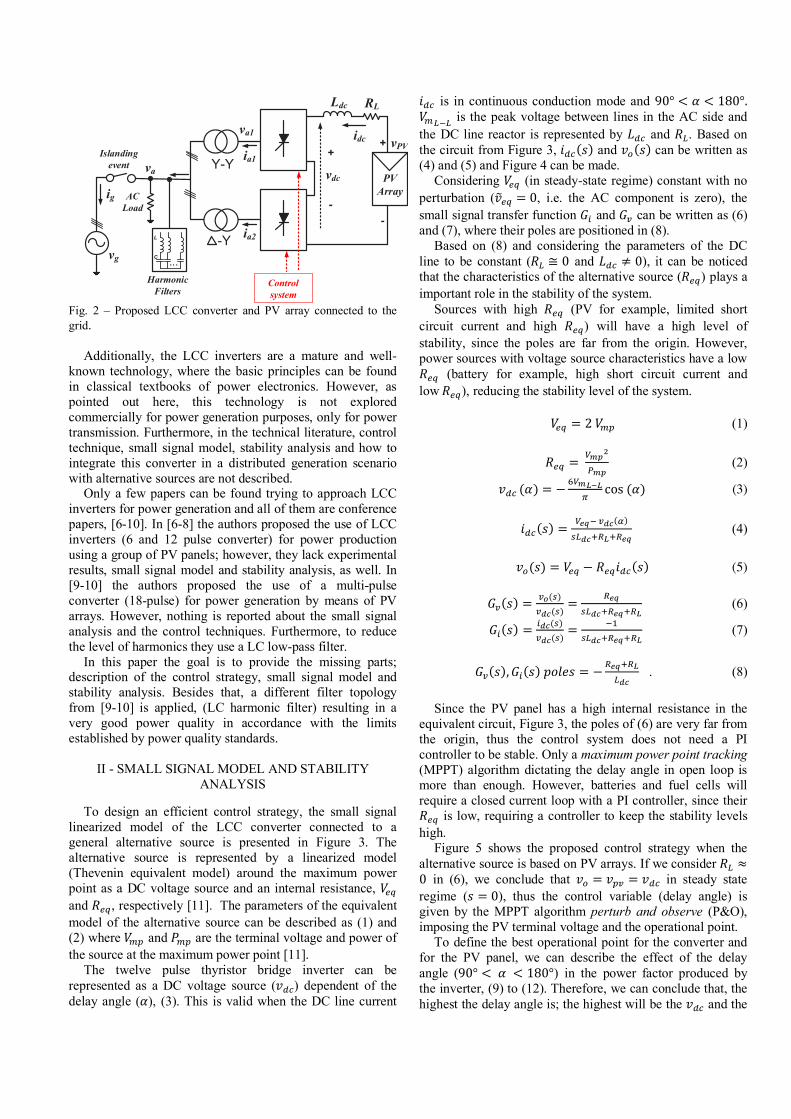
Figure 2 shows the proposed topology to produce energy
based on alternative sources with a twelve-pulse thyristor inverter. In this figure, the alternative source is represented by a photovoltaic array, but it could be replaced by fuel cell, battery bank or wind turbine (rectified). The main use of the proposed topology is for high power generation systems (based on alternative sources), 100 kW and higher, where nowadays VSC-SPWM (Sinusoidal Pulse Width Modulation) inverters are applied.
The VSC topologies switches at high frequencies (10 kHz and higher), need a very complex control strategy (PLL (Phase Looked-Loop) and Park transformation) and sophisticated active anti-islanding detection techniques. In the other hand, the LCC inverter topology was chosen due to the high reliability of the thyristor switches (higher than igbt), the low switching frequency (resulting in high conversion efficiency) and the easy control strategy, making it an interesting solution for power generation to be considered. When it comes to the disadvantages of the LCC compared to a typical VSC-SPWM inverter, we can include the lower power quality (because of the low switching frequency) and the need of a strong power grid in the AC side (because of the natural switching characteristics of thyristors). However, for remote high power generation systems, were maintenance cannot be served very often, the reliability and simplicity of the proposed topology should be considered over VSC, less reliable and more complex.
Fig. 1 – Typical LCC-HVDC power transmission system.
vg1
ig1
vg2
ig2
+
-
+
-vdc1 vdc2
Ldc RL
iL
Eletrôn. Potên., Joinville, v. 24, n. 2, p. 246-254, abr./jun. 2019 247
MODEL, DESIGN AND IMPLEMENTATION OF LCC CONVERTER FOR POWER GENERATION AND DISTRIBUTED GENERATION
Renan F. Bastos1, André L. A. Dias1, Ricardo Q. Machado2 1Universidade Federal de Ouro Preto (UFOP), Ouro Preto – MG, Brasil
2Universidade de São Paulo (USP), São Carlos – SP, Brasil e-mail: [email protected], [email protected], [email protected]
Abstract - This paper proposes to model, design and
implement a LCC (Line Commuted Converter) for power generation purpose, using alternative sources such as photovoltaic panel (PV), fuel cell and permanent magnet synchronous machine as the main power source. The converter is built with a full bridge twelve-pulse thyristor topology and connected to the alternative source through a line reactor. In order to extract maximum power from the sources, a classical maximum power point tracking algorithm (MPPT P&O) is applied. To validate the theoretical and simulated analysis, a 600 W experimental setup was built and controlled in closed loop. For the experimental results, the alternative source was represented by a variable DC power source in series with a resistor, making it possible to create controlled power steps and power events. During the operation, the grid current is analyzed in terms of power quality and an islanding event was created to analyze the converter’s behavior under critical conditions. All the experimental results show perfect conformity with the theory and simulation, proving the effectiveness of this converter topology for this purpose.
1 Keywords - Alternative sources, Distributed generation,
LCC converter, Power generation, Thyristor.
I - INTRODUCTION Over the years, the price for photovoltaic panels (PV)
have been dropping significantly, even quicker than the experts were predicting, from an average of 3.84 US$ /W in 2006 to approximately 0.61 US$ /W in 2015 [1]. This fast price drop made a shift in the financial focus of distributed generation systems from the PV panels to the power inverter since the production costs are not changing as fast as the first. Therefore, the study of alternative converter topologies for distributed generation is crucial in order to stimulate the growth of this field.
Line commuted converters (LCC) have been used for decades. As an example, ABB alone has around 120 LCC devices running around the world, some of which were already installed in the sixties [2]. This means that LCC converters are a very reliable and mature technology, used nowadays mainly for high voltage DC power transmission, LCC-HVDC (High Voltage Direct Current), Figure 1 [3-5]. Manuscript received 04/01/2019; first revision 06/03/2019; accepted for publication 08/06/2019, by recommendation of Editor Marcello Mezaroba. http://dx.doi.org/10.18618/REP.2019.2.0002
However, the LCC topology has not yet been explored commercially for power generation and especially for distributed generation by alternative sources. The Authors in [4,5] discuss the integration of wind farms into the DC line of a LCC power converter transmission line by means of a Current Source Converter (CSC) and Voltage Source Converter (VSC), respectively. But the use of a thyristor based LCC for power generation is not discussed.
Figure 2 shows the proposed topology to produce energy
based on alternative sources with a twelve-pulse thyristor inverter. In this figure, the alternative source is represented by a photovoltaic array, but it could be replaced by fuel cell, battery bank or wind turbine (rectified). The main use of the proposed topology is for high power generation systems (based on alternative sources), 100 kW and higher, where nowadays VSC-SPWM (Sinusoidal Pulse Width Modulation) inverters are applied.
The VSC topologies switches at high frequencies (10 kHz and higher), need a very complex control strategy (PLL (Phase Looked-Loop) and Park transformation) and sophisticated active anti-islanding detection techniques. In the other hand, the LCC inverter topology was chosen due to the high reliability of the thyristor switches (higher than igbt), the low switching frequency (resulting in high conversion efficiency) and the easy control strategy, making it an interesting solution for power generation to be considered. When it comes to the disadvantages of the LCC compared to a typical VSC-SPWM inverter, we can include the lower power quality (because of the low switching frequency) and the need of a strong power grid in the AC side (because of the natural switching characteristics of thyristors). However, for remote high power generation systems, were maintenance cannot be served very often, the reliability and simplicity of the proposed topology should be considered over VSC, less reliable and more complex.
Fig. 1 – Typical LCC-HVDC power transmission system.
vg1
ig1
vg2
ig2
+
-
+
-vdc1 vdc2
Ldc RL
iL
Fig. 2 – Proposed LCC converter and PV array connected to the grid.
Additionally, the LCC inverters are a mature and well-
known technology, where the basic principles can be found in classical textbooks of power electronics. However, as pointed out here, this technology is not explored commercially for power generation purposes, only for power transmission. Furthermore, in the technical literature, control technique, small signal model, stability analysis and how to integrate this converter in a distributed generation scenario with alternative sources are not described.
Only a few papers can be found trying to approach LCC inverters for power generation and all of them are conference papers, [6-10]. In [6-8] the authors proposed the use of LCC inverters (6 and 12 pulse converter) for power production using a group of PV panels; however, they lack experimental results, small signal model and stability analysis, as well. In [9-10] the authors proposed the use of a multi-pulse converter (18-pulse) for power generation by means of PV arrays. However, nothing is reported about the small signal analysis and the control techniques. Furthermore, to reduce the level of harmonics they use a LC low-pass filter.
In this paper the goal is to provide the missing parts; description of the control strategy, small signal model and stability analysis. Besides that, a different filter topology from [9-10] is applied, (LC harmonic filter) resulting in a very good power quality in accordance with the limits established by power quality standards.
II - SMALL SIGNAL MODEL AND STABILITY
ANALYSIS
To design an efficient control strategy, the small signal linearized model of the LCC converter connected to a general alternative source is presented in Figure 3. The alternative source is represented by a linearized model (Thevenin equivalent model) around the maximum power point as a DC voltage source and an internal resistance, 𝑉𝑉"# and 𝑅𝑅"#, respectively [11]. The parameters of the equivalent model of the alternative source can be described as (1) and (2) where 𝑉𝑉%& and 𝑃𝑃%& are the terminal voltage and power of the source at the maximum power point [11].
The twelve pulse thyristor bridge inverter can be represented as a DC voltage source (𝑣𝑣)*) dependent of the delay angle (𝛼𝛼), (3). This is valid when the DC line current
𝑖𝑖)* is in continuous conduction mode and 90° < 𝛼𝛼 < 180°. 𝑉𝑉%454 is the peak voltage between lines in the AC side and the DC line reactor is represented by 𝐿𝐿)* and 𝑅𝑅4. Based on the circuit from Figure 3, 𝑖𝑖)*(𝑠𝑠) and 𝑣𝑣:(𝑠𝑠) can be written as (4) and (5) and Figure 4 can be made.
Considering 𝑉𝑉"# (in steady-state regime) constant with no perturbation (𝑣𝑣;"# = 0, i.e. the AC component is zero), the small signal transfer function 𝐺𝐺> and 𝐺𝐺? can be written as (6) and (7), where their poles are positioned in (8).
Based on (8) and considering the parameters of the DC line to be constant (𝑅𝑅4 ≅ 0 and 𝐿𝐿)* ≠ 0), it can be noticed that the characteristics of the alternative source (𝑅𝑅"#) plays a important role in the stability of the system.
Sources with high 𝑅𝑅"# (PV for example, limited short circuit current and high 𝑅𝑅"#) will have a high level of stability, since the poles are far from the origin. However, power sources with voltage source characteristics have a low 𝑅𝑅"# (battery for example, high short circuit current and low𝑅𝑅"#), reducing the stability level of the system.
𝑉𝑉"# = 2𝑉𝑉%& (1)
𝑅𝑅"# = DEFG
HEF (2)
𝑣𝑣)*(𝛼𝛼) = −JDEKLK
Mcos(𝛼𝛼) (3)
𝑖𝑖)*(𝑠𝑠) =
DQR5?ST(U)
V4STWXKWXQR (4)
𝑣𝑣:(𝑠𝑠) = 𝑉𝑉"# − 𝑅𝑅"#𝑖𝑖)*(𝑠𝑠) (5)
𝐺𝐺?(𝑠𝑠) =
?Y(V)?ST(V)
= XQRV4STWXQRWXK
(6)
𝐺𝐺>(𝑠𝑠) =>ST(V)?ST(V)
= 5ZV4STWXQRWXK
(7)
𝐺𝐺?(𝑠𝑠), 𝐺𝐺>(𝑠𝑠)𝑝𝑝𝑝𝑝𝑝𝑝𝑝𝑝𝑠𝑠 = −
XQRWXK4ST
. (8)
Since the PV panel has a high internal resistance in the equivalent circuit, Figure 3, the poles of (6) are very far from the origin, thus the control system does not need a PI controller to be stable. Only a maximum power point tracking (MPPT) algorithm dictating the delay angle in open loop is more than enough. However, batteries and fuel cells will require a closed current loop with a PI controller, since their 𝑅𝑅"# is low, requiring a controller to keep the stability levels high.
Figure 5 shows the proposed control strategy when the alternative source is based on PV arrays. If we consider 𝑅𝑅4 ≈0 in (6), we conclude that 𝑣𝑣: = 𝑣𝑣&? = 𝑣𝑣)* in steady state regime (𝑠𝑠 = 0), thus the control variable (delay angle) is given by the MPPT algorithm perturb and observe (P&O), imposing the PV terminal voltage and the operational point.
To define the best operational point for the converter and for the PV panel, we can describe the effect of the delay angle (90° < 𝛼𝛼 < 180°) in the power factor produced by the inverter, (9) to (12). Therefore, we can conclude that, the highest the delay angle is; the highest will be the 𝑣𝑣)* and the
Y-Y
-Y...
L
C
Harmonic Filters
PVArray
Ldc RL
vdc
vPV+
-
+
-
idc
ia1
ia2
vg
ig
Islanding event va
Control system
ACLoad
va1

Eletrôn. Potên., Joinville, v. 24, n. 2, p. 246-254, abr./jun. 2019248
power factor of the power produced. From (12) we can estimate that the maximum power factor (PF) possible to achieve is 0.95 when 𝛼𝛼 ≅ 180º.
Based on (12) and Figure 6, we can design the PV array parameters according to grid voltage (𝑉𝑉%454) and the inverter gain (3), by making 𝑉𝑉%& = 0.9𝑣𝑣)*%bc. Thus, in order to keep the power factor high, the PV array must be stacked so 𝑉𝑉%& is slightly smaller than the highest DC voltage of the inverter (𝑣𝑣)*%bc is 𝑣𝑣)*(𝛼𝛼) when 𝛼𝛼 ≈ 180º). Therefore, the converter will always work with high 𝛼𝛼, making the PF high, as well.
Fig. 3 – LCC converter small signal linearized circuit.
Fig. 4 – Flow chart of small signal model of LCC converter
connected to alternative source.
Fig. 5 – PV panel proposed control strategy.
Fig. 6 – PV panel optimum operation region.
𝑖𝑖)* = 𝐼𝐼)*Xef =DQR5?STXKWXQR
(9)
𝑉𝑉gXef =
DEKLK√i√j
(10)
𝑰𝑰𝒈𝒈𝑹𝑹𝑹𝑹𝑹𝑹 = pji2𝐼𝐼)*Xef (11)
𝐹𝐹𝐹𝐹(𝛼𝛼) = H
|f|= ?ST>ST
iDstuv𝑰𝑰𝒈𝒈𝑹𝑹𝑹𝑹𝑹𝑹= − i
Mcos(𝛼𝛼) . (12)
Figure 7 shows the proposed control strategy when the
alternative source has a voltage source behavior (battery or fuel cell with low 𝑅𝑅"#). In this case, we have to control the current to avoid current surges. However, due to the low switching frequency (12 pulses or 720 Hz), the response time for any control action is very high, compromising the safety of the inverter.
In addition, a low 𝑅𝑅"# of the source results in low stability (6). In such case (𝑅𝑅"#low), the control strategy from Figure 8 can be applied to increase stability and controllability. For this topology, a DC-DC PWM converter can be connected in-between the source and the LCC inverter, increasing the stability of the source by increasing electronically the 𝑅𝑅"#. The topology of the DC-DC converter in this case is indifferent.
The delay angle of the LCC inverter is set fixed in a high value (𝛼𝛼 ≈ 180º) to ensure high power factor at the AC side (12) and the power delivery is defined by the DC-DC converter. Since the DC-DC converter switches at high frequency (𝑓𝑓Vx > 10𝑘𝑘𝑘𝑘𝑘𝑘), the bandwidth of the controller is higher, ensuring more stability.
Another benefit of Figure 8 is the capability of integrating different alternative sources and storage devices in a common DC link, connecting it to the grid by one LCC inverter, Figure 9. In this case all the storage devices and sources must be controlled in a power/current loop, since the voltage of the DC line is defined by the LCC inverter with fixed delay angle.
Since the LCC converter behaves like a voltage source (𝑣𝑣)*) when in CCM (continuous conduction mode) with constant α, 𝑣𝑣: can be described as (13) for Figure 10. Knowing that in steady state regime the DC current is constant, we can write (14). If 𝑅𝑅4 is very small we can conclude (15) or 𝑣𝑣:(𝑡𝑡) is constant, and its value is given by the LCC inverter. This equivalent circuit is represented by Figure 11. Thus we can conclude that the stability of the system is given by the DC converter when the LCC is connected as in Figures 8 and 9.
Fig. 7 – Fuel cell & battery control strategy.
Ldc RL
vo
+
-
idcReq+
-
vdc Veq
Alternative source Equivalente CircuitLCC inverter
+-sLdc+Req+RL
1vdc
Veq
Reqidc
+
-vo
p-6VmL-L cos(a)a
PVArray
Ldc RL
vPV+
-idc
vaSCR gate
drive circuitMPPT
vPV
idcDelay angle
Zero cross detection
vg
ig
va
12 pulse
vPV
idc Pmp
Vmp
Region of operation(vdc)
vdc max
Battery&
Fuel cell
Ldc RL
vo+
-idc
va Zero cross detection SCR gate
drive circuit
idc*PI
Delay angle
idc
12 pulsevg
ig

Eletrôn. Potên., Joinville, v. 24, n. 2, p. 246-254, abr./jun. 2019 249
power factor of the power produced. From (12) we can estimate that the maximum power factor (PF) possible to achieve is 0.95 when 𝛼𝛼 ≅ 180º.
Based on (12) and Figure 6, we can design the PV array parameters according to grid voltage (𝑉𝑉%454) and the inverter gain (3), by making 𝑉𝑉%& = 0.9𝑣𝑣)*%bc. Thus, in order to keep the power factor high, the PV array must be stacked so 𝑉𝑉%& is slightly smaller than the highest DC voltage of the inverter (𝑣𝑣)*%bc is 𝑣𝑣)*(𝛼𝛼) when 𝛼𝛼 ≈ 180º). Therefore, the converter will always work with high 𝛼𝛼, making the PF high, as well.
Fig. 3 – LCC converter small signal linearized circuit.
Fig. 4 – Flow chart of small signal model of LCC converter
connected to alternative source.
Fig. 5 – PV panel proposed control strategy.
Fig. 6 – PV panel optimum operation region.
𝑖𝑖)* = 𝐼𝐼)*Xef =DQR5?STXKWXQR
(9)
𝑉𝑉gXef =
DEKLK√i√j
(10)
𝑰𝑰𝒈𝒈𝑹𝑹𝑹𝑹𝑹𝑹 = pji2𝐼𝐼)*Xef (11)
𝐹𝐹𝐹𝐹(𝛼𝛼) = H
|f|= ?ST>ST
iDstuv𝑰𝑰𝒈𝒈𝑹𝑹𝑹𝑹𝑹𝑹= − i
Mcos(𝛼𝛼) . (12)
Figure 7 shows the proposed control strategy when the
alternative source has a voltage source behavior (battery or fuel cell with low 𝑅𝑅"#). In this case, we have to control the current to avoid current surges. However, due to the low switching frequency (12 pulses or 720 Hz), the response time for any control action is very high, compromising the safety of the inverter.
In addition, a low 𝑅𝑅"# of the source results in low stability (6). In such case (𝑅𝑅"#low), the control strategy from Figure 8 can be applied to increase stability and controllability. For this topology, a DC-DC PWM converter can be connected in-between the source and the LCC inverter, increasing the stability of the source by increasing electronically the 𝑅𝑅"#. The topology of the DC-DC converter in this case is indifferent.
The delay angle of the LCC inverter is set fixed in a high value (𝛼𝛼 ≈ 180º) to ensure high power factor at the AC side (12) and the power delivery is defined by the DC-DC converter. Since the DC-DC converter switches at high frequency (𝑓𝑓Vx > 10𝑘𝑘𝑘𝑘𝑘𝑘), the bandwidth of the controller is higher, ensuring more stability.
Another benefit of Figure 8 is the capability of integrating different alternative sources and storage devices in a common DC link, connecting it to the grid by one LCC inverter, Figure 9. In this case all the storage devices and sources must be controlled in a power/current loop, since the voltage of the DC line is defined by the LCC inverter with fixed delay angle.
Since the LCC converter behaves like a voltage source (𝑣𝑣)*) when in CCM (continuous conduction mode) with constant α, 𝑣𝑣: can be described as (13) for Figure 10. Knowing that in steady state regime the DC current is constant, we can write (14). If 𝑅𝑅4 is very small we can conclude (15) or 𝑣𝑣:(𝑡𝑡) is constant, and its value is given by the LCC inverter. This equivalent circuit is represented by Figure 11. Thus we can conclude that the stability of the system is given by the DC converter when the LCC is connected as in Figures 8 and 9.
Fig. 7 – Fuel cell & battery control strategy.
Ldc RL
vo
+
-
idcReq+
-
vdc Veq
Alternative source Equivalente CircuitLCC inverter
+-sLdc+Req+RL
1vdc
Veq
Reqidc
+
-vo
p-6VmL-L cos(a)a
PVArray
Ldc RL
vPV+
-idc
vaSCR gate
drive circuitMPPT
vPV
idcDelay angle
Zero cross detection
vg
ig
va
12 pulse
vPV
idc Pmp
Vmp
Region of operation(vdc)
vdc max
Battery&
Fuel cell
Ldc RL
vo+
-idc
va Zero cross detection SCR gate
drive circuit
idc*PI
Delay angle
idc
12 pulsevg
ig
Fig. 8 - Fuel cell & battery control strategy.
Fig. 9 – Integration of alternative sources and LCC inverter.
Fig. 10 – Stability analysis when the alternative source is
connected through a DC-DC converter.
𝑣𝑣:(𝑡𝑡) = 𝑣𝑣)* + 𝑅𝑅4𝑖𝑖)*(𝑡𝑡) + 𝐿𝐿)*)>ST())
(13)
𝑣𝑣:(𝑡𝑡) = 𝑣𝑣)* + 𝑅𝑅4𝑖𝑖)*(𝑡𝑡) (14)
𝑣𝑣:(𝑡𝑡) ≅ 𝑣𝑣)* if 𝑅𝑅4 ≅ 0 . (15)
Fig. 11 – Equivalent circuit of DC-DC converter connected to
LCC inverter.
III - SIMULATED AND EXPERIMENTAL RESULTS
As discussed in the introduction, LCC inverters have a low quality current output because of the low switching frequency. However, this quality can be easily improved by adding passive LC filters, Figure 12. In [9-10] the authors proposed the use of a LC low-pass filter with a series inductance of 𝐿𝐿 = 16𝑚𝑚𝑚𝑚 and a parallel RC branch, where 𝑅𝑅 = 7.5Ω and 𝐶𝐶 = 10𝜇𝜇𝜇𝜇 (16) and (17). However for high power converters this topology of filter increases the series impedance (𝐿𝐿 = 16𝑚𝑚𝑚𝑚 is 𝑋𝑋4=6 Ω) degrading the
performance of the inverter, caused by the high voltage drop in the inductance.
To avoid the inclusion of a series passive element, we propose the use of LC harmonic filters, adjusted to each harmonic component, (18) and (19), Figure 12. The LC harmonic filter creates a low impedance path to the ground for each chosen frequency.
Fig. 12 – LC harmonic filter and LC series low-pass filter.
>s(V)
>àâäQãåQã(V)= ZWVXç
VG4çWVXçWZ (16)
𝑓𝑓* =
ZjM√4ç
(17)
𝑍𝑍4ç(𝑠𝑠) =ZVç+ 𝑠𝑠𝐿𝐿 (18)
𝑓𝑓è =
ZjM√4ç
. (19) Comparing both filter topologies from Figure 12, the LC
harmonic filter does not include a series impedance, however it requires one set of filter for each harmonic. In this paper the LC harmonic filter was built for nine different harmonic frequencies, to ensure the required power quality (𝑇𝑇𝑚𝑚𝑇𝑇><5%).
The comparison of the performance for both filter topologies can be seen in Figures 13 and 14. The LC harmonic filter was tuned for 9 different frequencies (11th, 13th, 23th, 25th, 35th, 37th, 47th, 49th and 59th) using a 𝐶𝐶 = 1𝜇𝜇𝜇𝜇 and 𝐿𝐿 calculated as (19). The LC low-pass filter was tuned with 𝐿𝐿 = 1𝑚𝑚𝑚𝑚 (for low series impedance), 𝑅𝑅 = 1Ω and 𝐶𝐶 = 500𝜇𝜇𝜇𝜇, resulting in a cut-off frequency of 𝑓𝑓𝑓𝑓 =225𝑚𝑚𝐻𝐻.
As it can be seen in Figure 14, the harmonic filter has all the components under 1% of the fundamental, where the low-pass filter only performs better after the 29th harmonics. This makes the LC low-pass filter not enough to reach the required power quality for this topology of converter (final𝑇𝑇𝑚𝑚𝑇𝑇> ≅ 8%). In [9-10] the performance of the LC low-pass filter was better, since they use an 18 pulse converter (easier to filter with a low-pass), instead of the 12 pulse used in this work.
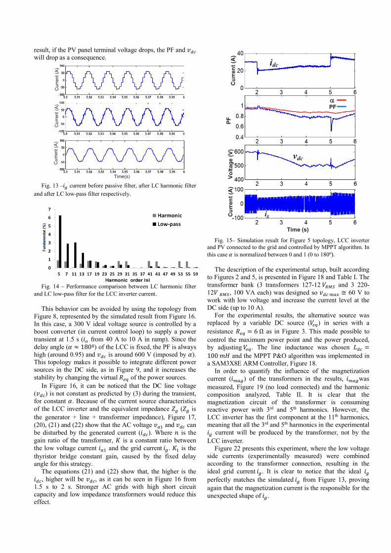
The simulated behavior of the topology presented in Figure 5, PV panels and LCC inverter connected to the grid controlled by MPPT algorithm, is shown in Figure 15. A power production transient was created at 2 s by the PV panels, where the𝑣𝑣%&and 𝑖𝑖%& are reduced (from 600 V, 30 A to 500 V, 25 A) and at 5 s they return to the previous values (600 V and 30 A). It can be noticed that the delay angle (𝛼𝛼) is adjusted in order to stay around the maximum power point. However, the adjustment of 𝛼𝛼makes the PF and 𝑣𝑣)* to change proportionally, as predicted in (12) and (3). As a
Ldc RL
vo+
-idc
io *PI
Fixed Delay Angle a 180
vg
io
Battery&
Fuel cell
DC
DC
pwm
12 pulse
ig
io
~ ~ o
Ldc
idc
Fixed Delay Angle a 180
vg
12 pulse
ig
~ ~ o DC
DC
DC
DC
DC
DC
Bat PV H2
Ldc RL
vo
+
-
idc+
-
vdc
LCC inverter
DC-DC converter
Alternative source
io
+
-vdc
DC-DC converter
Alternative source
io
ig L R
Cvg
iinverter
ig L
Cvg
iinverter
Eletrôn. Potên., Joinville, v. 24, n. 2, p. 246-254, abr./jun. 2019250
result, if the PV panel terminal voltage drops, the PF and 𝑣𝑣)* will drop as a consequence.
Fig. 13 –𝑖𝑖g current before passive filter, after LC harmonic filter
and after LC low-pass filter respectively.
Fig. 14 – Performance comparison between LC harmonic filter
and LC low-pass filter for the LCC inverter current. This behavior can be avoided by using the topology from
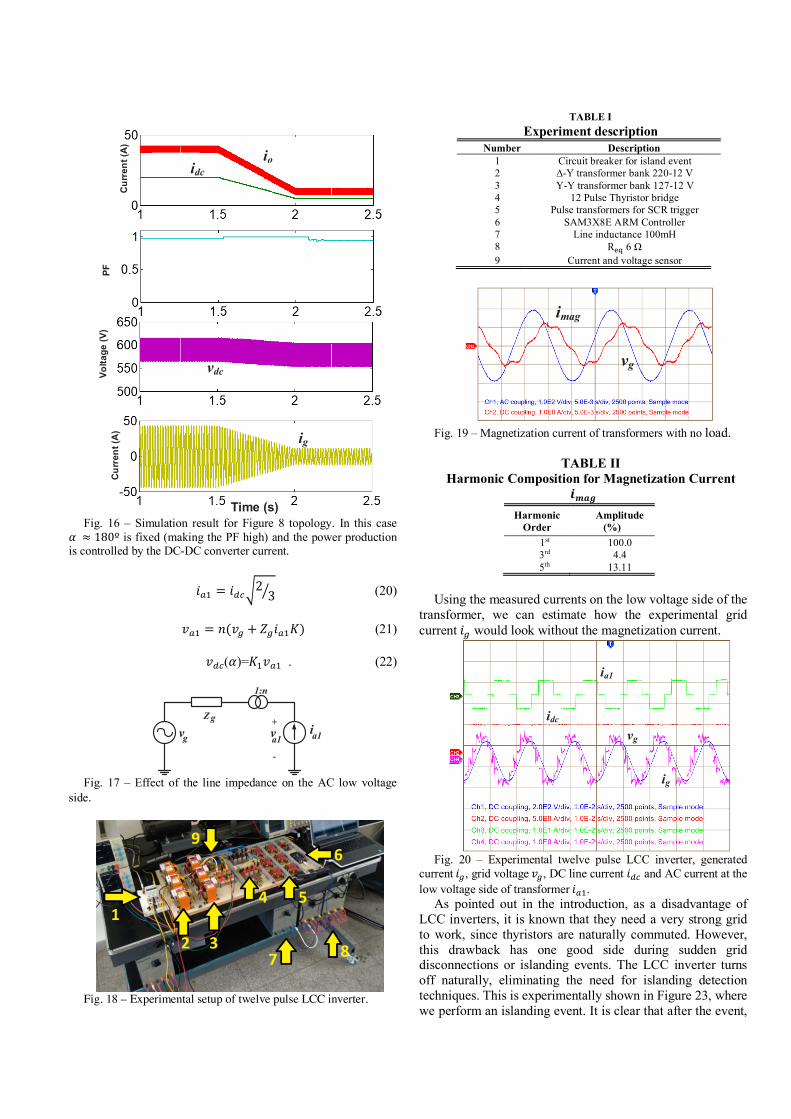
Figure 8, represented by the simulated result from Figure 16. In this case, a 300 V ideal voltage source is controlled by a boost converter (in current control loop) to supply a power transient at 1.5 s (𝑖𝑖: from 40 A to 10 A in ramp). Since the delay angle (𝛼𝛼 ≈ 180º) of the LCC is fixed, the PF is always high (around 0.95) and 𝑣𝑣)* is around 600 V (imposed by 𝛼𝛼). This topology makes it possible to integrate different power sources in the DC side, as in Figure 9, and it increases the stability by changing the virtual 𝑅𝑅"# of the power sources.
In Figure 16, it can be noticed that the DC line voltage (𝑣𝑣)*) is not constant as predicted by (3) during the transient, for constant 𝛼𝛼. Because of the current source characteristics of the LCC inverter and the equivalent impedance 𝑍𝑍g (𝑍𝑍g is the generator + line + transformer impedance), Figure 17, (20), (21) and (22) show that the AC voltage 𝑣𝑣bZ and 𝑣𝑣)* can be disturbed by the generated current (𝑖𝑖)*). Where 𝑛𝑛 is the gain ratio of the transformer, 𝐾𝐾 is a constant ratio between the low voltage current 𝑖𝑖bZ and the grid current𝑖𝑖g. 𝐾𝐾Z is the thyristor bridge constant gain, caused by the fixed delay angle for this strategy.
The equations (21) and (22) show that, the higher is the 𝑖𝑖)*, higher will be 𝑣𝑣)*, as it can be seen in Figure 16 from 1.5 s to 2 s. Stronger AC grids with high short circuit capacity and low impedance transformers would reduce this effect.
Fig. 15– Simulation result for Figure 5 topology, LCC inverter
and PV connected to the grid and controlled by MPPT algorithm. In this case 𝛼𝛼 is normalized between 0 and 1 (0 to 180º).
The description of the experimental setup, built according
to Figures 2 and 5, is presented in Figure 18 and Table I. The transformer bank (3 transformers 127-12𝑉𝑉Xef and 3 220-12𝑉𝑉Xef, 100 VA each) was designed so 𝑣𝑣)*%bc ≅ 60 V to work with low voltage and increase the current level at the DC side (up to 10 A).
For the experimental results, the alternative source was replaced by a variable DC source (𝑉𝑉"#) in series with a resistance 𝑅𝑅"# = 6Ω as in Figure 3. This made possible to control the maximum power point and the power produced, by adjusting𝑉𝑉"#. The line inductance was chosen 𝐿𝐿)* =100𝑚𝑚𝑚𝑚 and the MPPT P&O algorithm was implemented in a SAM3X8E ARM Controller, Figure 18.
In order to quantify the influence of the magnetization current (𝑖𝑖%bg) of the transformers in the results, 𝑖𝑖%bgwas measured, Figure 19 (no load connected) and the harmonic composition analyzed, Table II. It is clear that the magnetization circuit of the transformer is consuming reactive power with 3rd and 5th harmonics. However, the LCC inverter has the first component at the 11th harmonics, meaning that all the 3rd and 5th harmonics in the experimental 𝑖𝑖g current will be produced by the transformer, not by the LCC inverter.
Figure 22 presents this experiment, where the low voltage side currents (experimentally measured) were combined according to the transformer connection, resulting in the ideal grid current𝑖𝑖g. It is clear to notice that the ideal 𝑖𝑖g perfectly matches the simulated𝑖𝑖g from Figure 13, proving again that the magnetization current is the responsible for the unexpected shape of𝑖𝑖g.
Time(s)
Cur
rent
(A)
Cur
rent
(A)
Cur
rent
(A)
Time (s)Cu
rren
t (A
)Vo
ltage
(V)
PFCu
rren
t (A
)
aPF
vdc
ig
idc
Eletrôn. Potên., Joinville, v. 24, n. 2, p. 246-254, abr./jun. 2019 251
result, if the PV panel terminal voltage drops, the PF and 𝑣𝑣)* will drop as a consequence.
Fig. 13 –𝑖𝑖g current before passive filter, after LC harmonic filter
and after LC low-pass filter respectively.
Fig. 14 – Performance comparison between LC harmonic filter
and LC low-pass filter for the LCC inverter current. This behavior can be avoided by using the topology from
Figure 8, represented by the simulated result from Figure 16. In this case, a 300 V ideal voltage source is controlled by a boost converter (in current control loop) to supply a power transient at 1.5 s (𝑖𝑖: from 40 A to 10 A in ramp). Since the delay angle (𝛼𝛼 ≈ 180º) of the LCC is fixed, the PF is always high (around 0.95) and 𝑣𝑣)* is around 600 V (imposed by 𝛼𝛼). This topology makes it possible to integrate different power sources in the DC side, as in Figure 9, and it increases the stability by changing the virtual 𝑅𝑅"# of the power sources.
In Figure 16, it can be noticed that the DC line voltage (𝑣𝑣)*) is not constant as predicted by (3) during the transient, for constant 𝛼𝛼. Because of the current source characteristics of the LCC inverter and the equivalent impedance 𝑍𝑍g (𝑍𝑍g is the generator + line + transformer impedance), Figure 17, (20), (21) and (22) show that the AC voltage 𝑣𝑣bZ and 𝑣𝑣)* can be disturbed by the generated current (𝑖𝑖)*). Where 𝑛𝑛 is the gain ratio of the transformer, 𝐾𝐾 is a constant ratio between the low voltage current 𝑖𝑖bZ and the grid current𝑖𝑖g. 𝐾𝐾Z is the thyristor bridge constant gain, caused by the fixed delay angle for this strategy.
The equations (21) and (22) show that, the higher is the 𝑖𝑖)*, higher will be 𝑣𝑣)*, as it can be seen in Figure 16 from 1.5 s to 2 s. Stronger AC grids with high short circuit capacity and low impedance transformers would reduce this effect.
Fig. 15– Simulation result for Figure 5 topology, LCC inverter
and PV connected to the grid and controlled by MPPT algorithm. In this case 𝛼𝛼 is normalized between 0 and 1 (0 to 180º).
The description of the experimental setup, built according
to Figures 2 and 5, is presented in Figure 18 and Table I. The transformer bank (3 transformers 127-12𝑉𝑉Xef and 3 220-12𝑉𝑉Xef, 100 VA each) was designed so 𝑣𝑣)*%bc ≅ 60 V to work with low voltage and increase the current level at the DC side (up to 10 A).
For the experimental results, the alternative source was replaced by a variable DC source (𝑉𝑉"#) in series with a resistance 𝑅𝑅"# = 6Ω as in Figure 3. This made possible to control the maximum power point and the power produced, by adjusting𝑉𝑉"#. The line inductance was chosen 𝐿𝐿)* =100𝑚𝑚𝑚𝑚 and the MPPT P&O algorithm was implemented in a SAM3X8E ARM Controller, Figure 18.
In order to quantify the influence of the magnetization current (𝑖𝑖%bg) of the transformers in the results, 𝑖𝑖%bgwas measured, Figure 19 (no load connected) and the harmonic composition analyzed, Table II. It is clear that the magnetization circuit of the transformer is consuming reactive power with 3rd and 5th harmonics. However, the LCC inverter has the first component at the 11th harmonics, meaning that all the 3rd and 5th harmonics in the experimental 𝑖𝑖g current will be produced by the transformer, not by the LCC inverter.
Figure 22 presents this experiment, where the low voltage side currents (experimentally measured) were combined according to the transformer connection, resulting in the ideal grid current𝑖𝑖g. It is clear to notice that the ideal 𝑖𝑖g perfectly matches the simulated𝑖𝑖g from Figure 13, proving again that the magnetization current is the responsible for the unexpected shape of𝑖𝑖g.
Time(s)
Cur
rent
(A)
Cur
rent
(A)
Cur
rent
(A)
Time (s)
Curr
ent (
A)
Volta
ge (V
)PF
Curr
ent (
A)
aPF
vdc
ig
idc
Fig. 16 – Simulation result for Figure 8 topology. In this case
𝛼𝛼 ≈ 180º is fixed (making the PF high) and the power production is controlled by the DC-DC converter current.
𝑖𝑖bZ = 𝑖𝑖)*p2 3ò (20)
𝑣𝑣bZ = 𝑛𝑛(𝑣𝑣g + 𝑍𝑍g𝑖𝑖bZ𝐾𝐾) (21)
𝑣𝑣)*(𝛼𝛼)=𝐾𝐾Z𝑣𝑣bZ . (22)
Fig. 17 – Effect of the line impedance on the AC low voltage
side.
Fig. 18 – Experimental setup of twelve pulse LCC inverter.
TABLE I
Experiment description Number Description
1 Circuit breaker for island event 2 ∆-Y transformer bank 220-12 V 3 Y-Y transformer bank 127-12 V 4 12 Pulse Thyristor bridge 5 Pulse transformers for SCR trigger 6 SAM3X8E ARM Controller 7 Line inductance 100mH 8 Röõ 6 Ω 9 Current and voltage sensor
Fig. 19 – Magnetization current of transformers with no load.
TABLE II Harmonic Composition for Magnetization Current
𝒊𝒊𝒎𝒎𝒎𝒎𝒎𝒎 Harmonic
Order Amplitude
(%) 1st 100.0 3rd 4.4 5th 13.11
Using the measured currents on the low voltage side of the
transformer, we can estimate how the experimental grid current 𝑖𝑖g would look without the magnetization current.
Fig. 20 – Experimental twelve pulse LCC inverter, generated
current𝑖𝑖g, grid voltage𝑣𝑣g, DC line current 𝑖𝑖)* and AC current at the low voltage side of transformer𝑖𝑖bZ.
As pointed out in the introduction, as a disadvantage of LCC inverters, it is known that they need a very strong grid to work, since thyristors are naturally commuted. However, this drawback has one good side during sudden grid disconnections or islanding events. The LCC inverter turns off naturally, eliminating the need for islanding detection techniques. This is experimentally shown in Figure 23, where we perform an islanding event. It is clear that after the event,
Time (s)
Curr
ent (
A)
Volta
ge (V
)PF
Curr
ent (
A)
ig
vdc
ioidc
1:n
Zg
gv va1+
-
a1i
imag
vg
ia1
vg
ig
idc
Eletrôn. Potên., Joinville, v. 24, n. 2, p. 246-254, abr./jun. 2019252
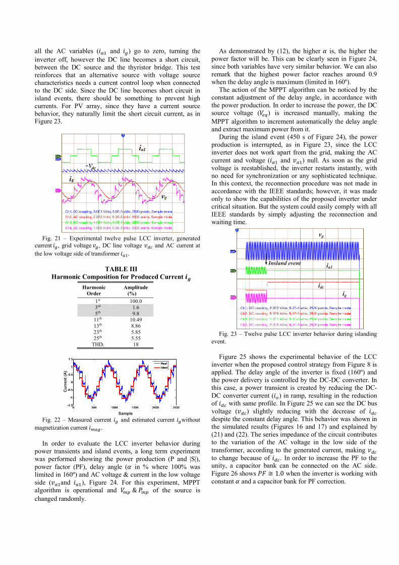
all the AC variables (𝑖𝑖bZ and 𝑖𝑖g) go to zero, turning the inverter off, however the DC line becomes a short circuit, between the DC source and the thyristor bridge. This test reinforces that an alternative source with voltage source characteristics needs a current control loop when connected to the DC side. Since the DC line becomes short circuit in island events, there should be something to prevent high currents. For PV array, since they have a current source behavior, they naturally limit the short circuit current, as in Figure 23.
Fig. 21 – Experimental twelve pulse LCC inverter, generated
current𝑖𝑖g, grid voltage𝑣𝑣g, DC line voltage 𝑣𝑣)* and AC current at the low voltage side of transformer𝑖𝑖bZ.
TABLE III
Harmonic Composition for Produced Current 𝒊𝒊𝒈𝒈 Harmonic
Order Amplitude
(%) 1st 100.0 3rd 1.6 5th 9.8 11th 10.49 13th 8.86 23th 5.85 25th 5.55
THDi 18
Fig. 22 – Measured current 𝑖𝑖g and estimated current 𝑖𝑖gwithout
magnetization current 𝑖𝑖%bg.
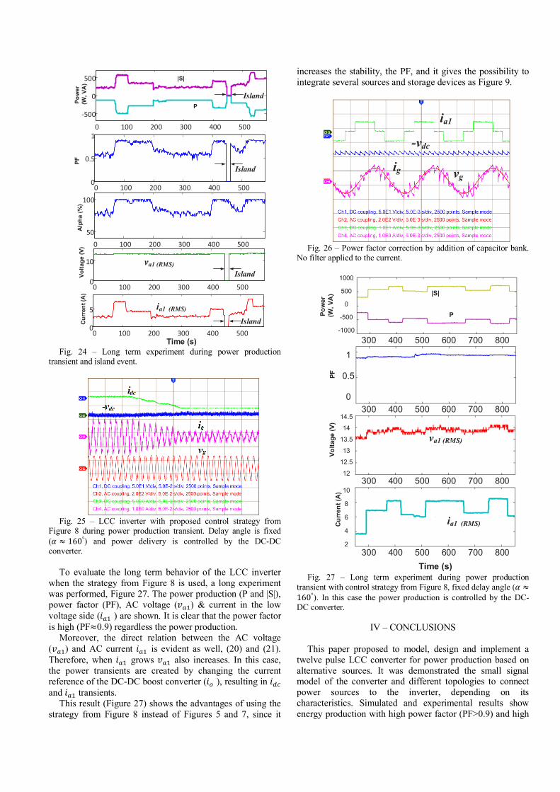
In order to evaluate the LCC inverter behavior during power transients and island events, a long term experiment was performed showing the power production (P and |S|), power factor (PF), delay angle (𝛼𝛼 in % where 100% was limited in 160º) and AC voltage & current in the low voltage side (𝑣𝑣bZand 𝑖𝑖bZ), Figure 24. For this experiment, MPPT algorithm is operational and 𝑉𝑉%&&𝑃𝑃%& of the source is changed randomly.
As demonstrated by (12), the higher 𝛼𝛼 is, the higher the power factor will be. This can be clearly seen in Figure 24, since both variables have very similar behavior. We can also remark that the highest power factor reaches around 0.9 when the delay angle is maximum (limited in 160º).
The action of the MPPT algorithm can be noticed by the constant adjustment of the delay angle, in accordance with the power production. In order to increase the power, the DC source voltage (𝑉𝑉"#) is increased manually, making the MPPT algorithm to increment automatically the delay angle and extract maximum power from it.
During the island event (450 s of Figure 24), the power production is interrupted, as in Figure 23, since the LCC inverter does not work apart from the grid, making the AC current and voltage (𝑖𝑖bZ and 𝑣𝑣bZ) null. As soon as the grid voltage is reestablished, the inverter restarts instantly, with no need for synchronization or any sophisticated technique. In this context, the reconnection procedure was not made in accordance with the IEEE standards; however, it was made only to show the capabilities of the proposed inverter under critical situation. But the system could easily comply with all IEEE standards by simply adjusting the reconnection and waiting time.
Fig. 23 – Twelve pulse LCC inverter behavior during islanding
event. Figure 25 shows the experimental behavior of the LCC
inverter when the proposed control strategy from Figure 8 is applied. The delay angle of the inverter is fixed (160º) and the power delivery is controlled by the DC-DC converter. In this case, a power transient is created by reducing the DC-DC converter current (𝑖𝑖:) in ramp, resulting in the reduction of 𝑖𝑖)* with same profile. In Figure 25 we can see the DC bus voltage (𝑣𝑣)*) slightly reducing with the decrease of 𝑖𝑖)* despite the constant delay angle. This behavior was shown in the simulated results (Figures 16 and 17) and explained by (21) and (22). The series impedance of the circuit contributes to the variation of the AC voltage in the low side of the transformer, according to the generated current, making 𝑣𝑣)* to change because of 𝑖𝑖)*. In order to increase the PF to the unity, a capacitor bank can be connected on the AC side. Figure 26 shows 𝑃𝑃𝑃𝑃 ≅ 1.0 when the inverter is working with constant 𝛼𝛼 and a capacitor bank for PF correction.
Sample
Curr
ent (
A)
Insland event
vg
ia1
idc
ig
Eletrôn. Potên., Joinville, v. 24, n. 2, p. 246-254, abr./jun. 2019 253
all the AC variables (𝑖𝑖bZ and 𝑖𝑖g) go to zero, turning the inverter off, however the DC line becomes a short circuit, between the DC source and the thyristor bridge. This test reinforces that an alternative source with voltage source characteristics needs a current control loop when connected to the DC side. Since the DC line becomes short circuit in island events, there should be something to prevent high currents. For PV array, since they have a current source behavior, they naturally limit the short circuit current, as in Figure 23.
Fig. 21 – Experimental twelve pulse LCC inverter, generated
current𝑖𝑖g, grid voltage𝑣𝑣g, DC line voltage 𝑣𝑣)* and AC current at the low voltage side of transformer𝑖𝑖bZ.
TABLE III
Harmonic Composition for Produced Current 𝒊𝒊𝒈𝒈 Harmonic
Order Amplitude
(%) 1st 100.0 3rd 1.6 5th 9.8 11th 10.49 13th 8.86 23th 5.85 25th 5.55
THDi 18
Fig. 22 – Measured current 𝑖𝑖g and estimated current 𝑖𝑖gwithout
magnetization current 𝑖𝑖%bg.
In order to evaluate the LCC inverter behavior during power transients and island events, a long term experiment was performed showing the power production (P and |S|), power factor (PF), delay angle (𝛼𝛼 in % where 100% was limited in 160º) and AC voltage & current in the low voltage side (𝑣𝑣bZand 𝑖𝑖bZ), Figure 24. For this experiment, MPPT algorithm is operational and 𝑉𝑉%&&𝑃𝑃%& of the source is changed randomly.
As demonstrated by (12), the higher 𝛼𝛼 is, the higher the power factor will be. This can be clearly seen in Figure 24, since both variables have very similar behavior. We can also remark that the highest power factor reaches around 0.9 when the delay angle is maximum (limited in 160º).
The action of the MPPT algorithm can be noticed by the constant adjustment of the delay angle, in accordance with the power production. In order to increase the power, the DC source voltage (𝑉𝑉"#) is increased manually, making the MPPT algorithm to increment automatically the delay angle and extract maximum power from it.
During the island event (450 s of Figure 24), the power production is interrupted, as in Figure 23, since the LCC inverter does not work apart from the grid, making the AC current and voltage (𝑖𝑖bZ and 𝑣𝑣bZ) null. As soon as the grid voltage is reestablished, the inverter restarts instantly, with no need for synchronization or any sophisticated technique. In this context, the reconnection procedure was not made in accordance with the IEEE standards; however, it was made only to show the capabilities of the proposed inverter under critical situation. But the system could easily comply with all IEEE standards by simply adjusting the reconnection and waiting time.
Fig. 23 – Twelve pulse LCC inverter behavior during islanding
event. Figure 25 shows the experimental behavior of the LCC
inverter when the proposed control strategy from Figure 8 is applied. The delay angle of the inverter is fixed (160º) and the power delivery is controlled by the DC-DC converter. In this case, a power transient is created by reducing the DC-DC converter current (𝑖𝑖:) in ramp, resulting in the reduction of 𝑖𝑖)* with same profile. In Figure 25 we can see the DC bus voltage (𝑣𝑣)*) slightly reducing with the decrease of 𝑖𝑖)* despite the constant delay angle. This behavior was shown in the simulated results (Figures 16 and 17) and explained by (21) and (22). The series impedance of the circuit contributes to the variation of the AC voltage in the low side of the transformer, according to the generated current, making 𝑣𝑣)* to change because of 𝑖𝑖)*. In order to increase the PF to the unity, a capacitor bank can be connected on the AC side. Figure 26 shows 𝑃𝑃𝑃𝑃 ≅ 1.0 when the inverter is working with constant 𝛼𝛼 and a capacitor bank for PF correction.
Sample
Curr
ent (
A)
Insland event
vg
ia1
idc
ig
Fig. 24 – Long term experiment during power production
transient and island event.
Fig. 25 – LCC inverter with proposed control strategy from
Figure 8 during power production transient. Delay angle is fixed (𝛼𝛼 ≈ 160°) and power delivery is controlled by the DC-DC converter.
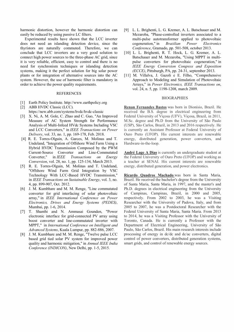
To evaluate the long term behavior of the LCC inverter
when the strategy from Figure 8 is used, a long experiment was performed, Figure 27. The power production (P and |S|), power factor (PF), AC voltage (𝑣𝑣bZ) & current in the low voltage side (𝑖𝑖bZ ) are shown. It is clear that the power factor is high (PF≈0.9) regardless the power production.
Moreover, the direct relation between the AC voltage (𝑣𝑣bZ) and AC current 𝑖𝑖bZ is evident as well, (20) and (21). Therefore, when 𝑖𝑖bZ grows 𝑣𝑣bZ also increases. In this case, the power transients are created by changing the current reference of the DC-DC boost converter (𝑖𝑖: ), resulting in 𝑖𝑖)* and 𝑖𝑖bZ transients.
This result (Figure 27) shows the advantages of using the strategy from Figure 8 instead of Figures 5 and 7, since it
increases the stability, the PF, and it gives the possibility to integrate several sources and storage devices as Figure 9.
Fig. 26 – Power factor correction by addition of capacitor bank.
No filter applied to the current.
Fig. 27 – Long term experiment during power production
transient with control strategy from Figure 8, fixed delay angle (𝛼𝛼 ≈160°). In this case the power production is controlled by the DC-DC converter.
IV – CONCLUSIONS
This paper proposed to model, design and implement a twelve pulse LCC converter for power production based on alternative sources. It was demonstrated the small signal model of the converter and different topologies to connect power sources to the inverter, depending on its characteristics. Simulated and experimental results show energy production with high power factor (PF>0.9) and high
0 100 200 300 400 500
-500
0
500
0 100 200 300 400 5000
0.5
1
0 100 200 300 400 50050
100
0 100 200 300 400 5000
10
0 100 200 300 400 5000
5
Time (s)
Curr
ent (
A)
Volta
ge (V
)Al
pha
(%)
PFPo
wer
(W, V
A)
|S|
PIsland
Island
Island
Island
ia1 (RMS)
va1 (RMS)
ia1
-vdc
ig vg
Curr
ent (
A)
Volta
ge (V
)PF
Pow
er (W
, VA
)
300 400 500 600 700 800
300 400 500 600 700 800
300 400 500 600 700 800
300 400 500 600 700 800 1
0.5
0
1000
500
0
-500
-1000
14.5
14
13.5
13
12.5
12
10
8
6
4
2
|S|
P
va1 (RMS)
ia1 (RMS)
Time (s)
Eletrôn. Potên., Joinville, v. 24, n. 2, p. 246-254, abr./jun. 2019254
harmonic distortion, however the harmonic distortion can easily be reduced by using passive LC filters.
Experimental results have shown that the LCC inverter does not need an islanding detection device, since the thyristors are naturally commuted. Therefore, we can conclude that LCC inverters are a very good solution to connect high power sources to the three-phase AC grid, since it is very reliable, efficient, easy to control and there is no need for synchronism techniques or islanding detection systems, making it the perfect solution for big solar power plants or for integration of alternative sources into the AC system. However, the use of harmonic filter is mandatory in order to achieve the power quality requirements.
REFERENCES
[1] Earth Policy Institute. http://www.earthpolicy.org [2] ABB HVDC Classic (LCC).
https://new.abb.com/systems/hvdc/hvdc-classic [3] X. Ni, A. M. Gole, C. Zhao and C. Guo, "An Improved
Measure of AC System Strength for Performance Analysis of Multi-Infeed HVdc Systems Including VSC and LCC Converters," in IEEE Transactions on Power Delivery, vol. 33, no. 1, pp. 169-178, Feb. 2018.
[4] R. E. Torres-Olguin, A. Garces, M. Molinas and T. Undeland, "Integration of Offshore Wind Farm Using a Hybrid HVDC Transmission Composed by the PWM Current-Source Converter and Line-Commutated Converter," in IEEE Transactions on Energy Conversion, vol. 28, no. 1, pp. 125-134, March 2013.
[5] R. E. Torres-Olguin, M. Molinas and T. Undeland, "Offshore Wind Farm Grid Integration by VSC Technology With LCC-Based HVDC Transmission," in IEEE Transactions on Sustainable Energy, vol. 3, no. 4, pp. 899-907, Oct. 2012.
[6] J. M. Kumbhare and M. M. Renge, "Line commutated converter for grid interfacing of solar photovoltaic array," in IEEE International Conference on Power Electronics, Drives and Energy Systems (PEDES), Mumbai, pp. 1-6, 2014.
[7] T. Shanthi and N. Ammasai Gounden, "Power electronic interface for grid-connected PV array using boost converter and line-commutated inverter with MPPT," in International Conference on Intelligent and Advanced Systems, Kuala Lumpur, pp. 882-886, 2007.
[8] J. M. Kumbhare and M. M. Renge, "Twelve pulse LCC based grid tied solar PV system for improved power quality and harmonic mitigation," in Annual IEEE India Conference (INDICON), New Delhi, pp. 1-5, 2015.
[9] L. L. Brighenti, L. G. Kremer, A. L. Batschauer and M. Mezaroba, "Phase-controlled inverters associated to a multi-pulse autotransformer applied to photovoltaic cogeneration," in Brazilian Power Electronics Conference, Gramado, pp. 501-508, october 2013.
[10] L. L. Brighenti, R. T. Hock, L. G. Kremer, A. L. Batschauer and M. Mezaroba, "Using MPPT in multi-pulse converters for photovoltaic cogeneration," in IEEE Energy Conversion Congress and Exposition (ECCE), Pittsburgh, PA, pp. 24-31, september 2013.
[11] M. Villalva, J. Gazoli e E. Filho, “Comprehensive Approach to Modeling and Simulation of Photovoltaic Arrays,” in Power Electronics, IEEE Transactions on, vol. 24, n. 5, pp. 1198-1208, march 2009.
BIOGRAPHIES
Renan Fernandes Bastos was born in Dionísio, Brazil. He received the B.S. degree in electrical engineering from Federal University of Viçosa (UFV), Viçosa, Brazil, in 2011, M.Sc. degree and Ph.D from the University of São Paulo (USP), São Carlos, Brazil, in 2013 and 2016 respectively. He is currently an Assistant Professor at Federal University of Ouro Preto (UFOP). His current interests are renewable energy, distributed generation, power converters, and Hardware-in-the-loop. André Lage A Dias is currently an undergraduate student at the Federal University of Ouro Preto (UFOP) and working as a teacher at SENAI. His current interests are renewable energy, distributed generation, and power electronics. Ricardo Quadros Machado was born in Santa Maria, Brazil. He received the bachelor's degree from the University of Santa Maria, Santa Maria, in 1997, and the master's and Ph.D. degrees in electrical engineering from the University of Campinas, Campinas, Brazil, in 2000 and 2005, respectively. From 2002 to 2003, he was a Visiting Researcher with the University of Padova, Italy, and from 2005 to 2007, he was a Postdoctoral Researcher with the Federal University of Santa Maria, Santa Maria. From 2013 to 2014, he was a Visiting Professor with the University of Toronto, Canada. He is currently a Professor with the Department of Electrical Engineering, University of São Paulo, São Carlos, Brazil. His main research interests include processing of energy in dc/dc and dc/ac converters, digital control of power converters, distributed generation systems, smart grids, and control of renewable energy sources.