MODEL CB-PRO FUSED/CONTACTOR CIRCUIT BREAKER...
76
MODEL CB-PRO FUSED/CONTACTOR CIRCUIT BREAKER SYSTEM May 9, 2001 Manual Part # 180-0478B
Transcript of MODEL CB-PRO FUSED/CONTACTOR CIRCUIT BREAKER...
MODEL CB-PRO
FUSED/CONTACTOR
CIRCUIT BREAKER
SYSTEM
May 9, 2001
Manual Part # 180-0478B

TABLE OF CONTENTS
TITLE PAGE 1. Introduction 1
2. Features 3
3. Specifications
3.1. CB-PRO Specifications 5
3.2.1. CB-PRO 225 Specifications 6
3.2.3. CB-PRO 300 Specifications 6
3.3.1. CB-PRO 450 Specifications 7
3.4.1. CB-PRO 550 Specifications 8
4. Description
4.1. CB-PRO Configurations 10
4.1.1. CB-PRO 225 10
4.1.2. CB-PRO 300 10
4.1.3. CB-PRO 450 10
4.1.4. CB-PRO 550 10
4.1.5. CB-PRO 800 11
4.2. Contactor 11
4.3. Fuses 12
4.4. Contactor and Fuse Open Time Coordination 12
4.5. Phase Current Transformers 13
4.6. Ground Fault Current Transformers 13
4.7. Voltage Interface Module 14
4.8. Motor Start-up Current Detection 14
4.9. Electronic Control Unit 15
4.9.1. RS-485 Communications 15
4.9.2. PLC Monitor and Control 15
4.9.3. Three Phase Voltage Measurement 15
4.9.4. Control Voltage Measurement 15
4.9.5. Three Phase Current Measurement 16
4.9.6. Ground Fault Current Measurement 16
4.9.7. Fuse Open Detection 17
4.9.8. Stuck Bottle Detection 17
4.9.9. Auxiliary Contact Monitor 17
4.9.10. Solid State Switch 17
4.9.11. Ground Monitor Relay, Remote 17
Stop, Front Panel Stop Switch
4.9.12. Front Panel Controls and Indicators 18
4.9.12.1. LCD Display 18
4.9.12.2. Keypad 18
4.9.12.3. Close Switch 18
4.9.12.4. Key Switch 19
4.9.12.5. Open Switch 19

TABLE OF CONTENTS(Cont.)
TITLE PAGE 4.9.12.6. LEDS 17
4.9.13. Display Menus 17
4.9.13.1 CB-PRO Main Menu 18
4.9.13.1.1 CB-PRO Status Menu Page 1 18
4.9.13.1.2 CB-PRO Phase Voltages Status Menu 19
4.9.13.1.3 CB-PRO Phase Currents Status Menu 19
4.9.13.1.4 CB-PRO Phase Angle Status Menu 19
4.9.13.1.5 CB-PRO Last Start Current 19
Status Menu
4.9.13.1.6 CB-PRO Circuit Configuration 19
Status Menu
4.9.13.1.7 CB-PRO Ground Fault Current 20
Status Menu
4.9.13.1.8 CB-PRO Last Start Phase Angle 20
Status Menu
4.9.13.1.9 CB-PRO Trip Settings 1 Status Men 20
TABLE OF CONTENTS(Cont.)
TITLE PAGE 4.9.12.6. LEDS 19
4.9.13. Display Menus 19
4.9.13.1. CB-PRO Main Menu 20
4.9.13.1.1. CB-PRO Status Menu Page 1 20
4.9.13.1.2. CB-PRO Phase Voltages 21
Status Menu
4.9.13.1.3. CB-PRO Phase Currents 21
Status Menu
4.9.13.1.4. CB-PRO Phase Angle Status Menu 21
4.9.13.1.5. CB-PRO Last Start Current 21
Status Menu
4.9.13.1.6. CB-PRO Circuit Configuration 21
Status Menu
4.9.13.1.7. CB-PRO Ground Fault Current 22
Status Menu
4.9.13.1.8. CB-PRO Last Start Phase Angle 22
Status Menu
4.9.13.1.9. CB-PRO Trip Settings 1 22
Status Menu
4.9.13.1.10. CB-PRO Trip Settings 2 22
Status Menu
4.9.13.1.11. CB-PRO Status Menu Page 2 23
4.9.13.1.12. CB-PRO Communications 23
Status Menu
4.9.13.1.13. CB-PRO Breaker Fault Type 23
Status Menu
4.9.13.1.14. CB-PRO Front Panel Switches 24
Status Menu
4.9.13.1.15. CB-PRO Fuse and Contactor 24
Bottle Status Menu
4.9.13.1.16. CB-PRO Remote Control 24
Switches #1 Status Menu
4.9.13.1.17. CB-PRO Remote Control 24
Switches #2 Status Menu
4.9.13.1.18. CB-PRO Contactor Close Time 25
Status Menu
4.9.13.1.19. CB-PRO Last Over Current 25
Status Menu
4.9.13.1.20. CB-PRO Last Ground Fault 25
Current Status Menu
TABLE OF CONTENTS(Cont.)
TITLE PAGE 4.9.13.1.21. CB-PRO Status Menu Page 3 26
4.9.13.1.22. CB-PRO Ground Fault Test 26
Status Menu
4.9.13.1.23. CB-PRO Date and Time 26
Status Menu
4.9.13.1.24. CB-PRO Last Fault Status Menu 26
4.9.13.2. CB-PRO Configuration Menus 27
4.9.13.2.1. CB-PRO Enter/Change Pass Code 27
Configuration Menu
4.9.13.2.2. CB-PRO Enter Pass Code 27
Configuration Menu
4.9.13.2.3. CB-PRO Change Pass Code 28
Configuration Menu
4.9.13.2.4. CB-PRO Configuration Menu 28
Page 1
4.9.13.2.5. CB-PRO Contactor and CT 29
Configuration Menu
4.9.13.2.6. CB-PRO Zero Currents 29
Configuration Menu
4.9.13.2.7. CB-PRO Select Motor Overload 29
Configuration Menu
4.9.13.2.8. CB-PRO Communications 30
Configuration Menu
4.9.13.2.9. CB-PRO Set Ground Fault Current 30
Trip Config Menu
4.9.13.2.10. CB-PRO Set Thermal Current 30
Trip Config Menu
4.9.13.2.11. CB-PRO Set Magnetic Current 31
Trip Config Menu
4.9.13.2.12. CB-PRO Set Phase Current 31
Imbalance Trip Config Menu
4.9.13.2.13. CB-PRO Set % Undervoltage 31
Trip Config Menu
4.9.13.2.14. CB-PRO Configuration Menu 32
Page 2
4.9.13.2.15. CB-PRO Delay for % Trips 32
Configuration Menu
4.9.13.2.16. CB-PRO Set Date and Time 32
Configuration Menu
4.9.13.2.17. CB-PRO Select Phase Voltage 33
Configuration Menu
TABLE OF CONTENTS(Cont.)
TITLE PAGE 4.9.13.2.18. CB-PRO Select Contactor 33
Close Delay Time
5. Operation 34
5.1. Fuse/Contactor Fault Disconnect Coordination 34
5.2. CB-PRO Configuration 34
5.3. Using Status Menus to Confirm Configuration 35
5.4. Reset of Faults 36
5.5. Closing the Contactor 36
5.6. Caution 36
6. Installation 38
6.1. CB-PRO 225 and 300 Components 38
6.1.1. CB-PRO 225 and 300 Power Components
Connection 38
6.2. CB-PRO 450 Components 39
6.2.1. CB-PRO 450 Power Components Connection 39
6.3. CB-PRO 550 Components 40
6.3.1. CB-PRO 550 Power Components Connection 41
6.4. CB-PRO Monitor and Control Components 41
Connection
7. Troubleshooting 46
7.1. CB-PRO Fault Menu Display Message 46
7.2. More Troubleshooting 47
8. Spare Parts 48
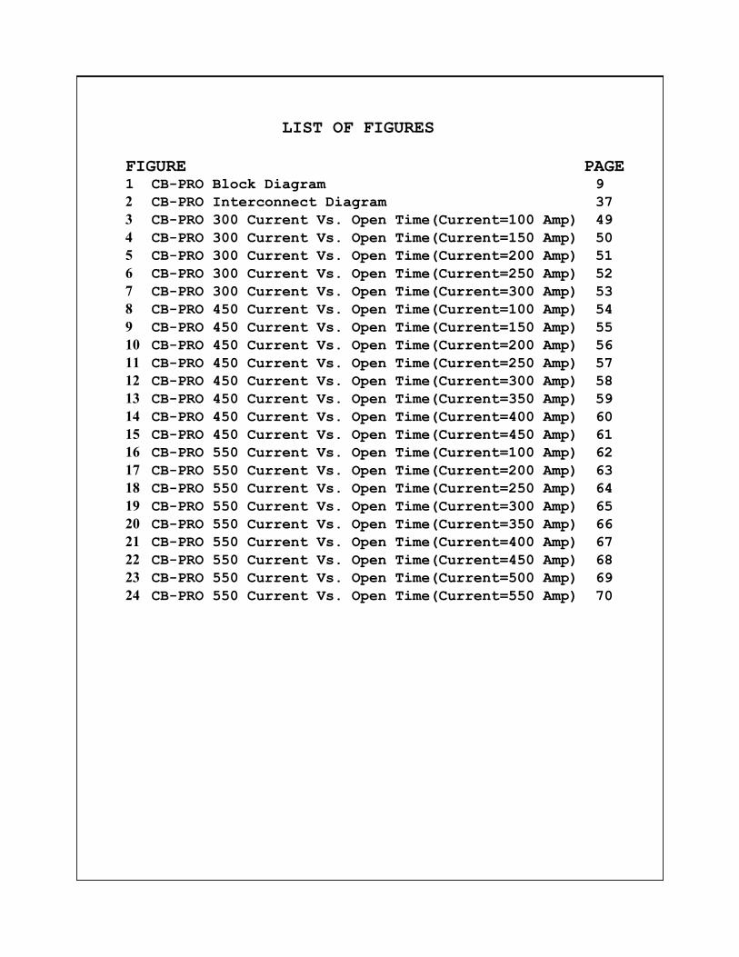
LIST OF FIGURES
FIGURE PAGE 1 CB-PRO Block Diagram 9
2 CB-PRO Interconnect Diagram 37
3 CB-PRO 300 Current Vs. Open Time(Current=100 Amp) 49
4 CB-PRO 300 Current Vs. Open Time(Current=150 Amp) 50
5 CB-PRO 300 Current Vs. Open Time(Current=200 Amp) 51
6 CB-PRO 300 Current Vs. Open Time(Current=250 Amp) 52
7 CB-PRO 300 Current Vs. Open Time(Current=300 Amp) 53
8 CB-PRO 450 Current Vs. Open Time(Current=100 Amp) 54
9 CB-PRO 450 Current Vs. Open Time(Current=150 Amp) 55
10 CB-PRO 450 Current Vs. Open Time(Current=200 Amp) 56
11 CB-PRO 450 Current Vs. Open Time(Current=250 Amp) 57
12 CB-PRO 450 Current Vs. Open Time(Current=300 Amp) 58
13 CB-PRO 450 Current Vs. Open Time(Current=350 Amp) 59
14 CB-PRO 450 Current Vs. Open Time(Current=400 Amp) 60
15 CB-PRO 450 Current Vs. Open Time(Current=450 Amp) 61
16 CB-PRO 550 Current Vs. Open Time(Current=100 Amp) 62
17 CB-PRO 550 Current Vs. Open Time(Current=200 Amp) 63
18 CB-PRO 550 Current Vs. Open Time(Current=250 Amp) 64
19 CB-PRO 550 Current Vs. Open Time(Current=300 Amp) 65
20 CB-PRO 550 Current Vs. Open Time(Current=350 Amp) 66
21 CB-PRO 550 Current Vs. Open Time(Current=400 Amp) 67
22 CB-PRO 550 Current Vs. Open Time(Current=450 Amp) 68
23 CB-PRO 550 Current Vs. Open Time(Current=500 Amp) 69
24 CB-PRO 550 Current Vs. Open Time(Current=550 Amp) 70

1. Introduction
The first model of AMR's vacuum circuit breaker, the
CB-1000-450, was designed for use in mining applications. It
provides a more safe and reliable circuit protection system
than the molded case circuit breaker used in power
distributions centers. It can also be used as a belt or pump
controller to replace the combination of the molded case
circuit breaker, control contactor and overcurrent relay.
Three more models of the CB-1000 were developed later,
CB-1000-300, CB-1000-600, and CB-1000-800.
The CB-100 was developed next and it is a simplified
version of the CB-1000. It does not have the ground monitor
or the mine wide monitoring system interface. Currently,
there are four models available. They are the:
CB-100-300—(300 amperes continuous rating);
CB-100-450—(450 amperes continuous rating);
CB-100-600—(600 amperes continuous rating);
CB-100-800—(800 amperes continuous rating).
The CB-200 was developed next. It is a modification of the
CB-100 and was developed to satisify the need to provide
control of lower currents. The three phase current
transformers and the rating plug were re-designed to allow
operation over the full load current range of 14 to 225
amperes.
The CB-PRO circuit breaker was developed to provide the
user with an improved version of the CB-1000/100/200 series of
circuit breakers. The same contactors and fuses that have
proven themselves while used in the CB-1000/100/200 circuit
breakers are also used in the CB-PRO circuit breaker.
The CB-PRO is composed of four primary components. These
components consist of the contactor, fuses, voltage interface
module and electronic control unit. The voltage interface
module and electronic control unit differ from those used in
the CB-1000/100/200 design. The electronic control unit has
been improved by using a microprocessor to evaluate circuit
parameters and compare them to easily set trip points.
Page 1
The typical CB-PRO circuit protection panel will contain
the following components:
Vacuum Bottle Contactor with control solenoid
The contactor switches three phase power to the load.
Current Limiting Fuses
The fuses limit three phase fault current and disconnects
the load under extreme fault currents.
Phase Current Transformers
The current transformers monitor phase currents levels
for thermal and magnetic trips.
Ground Fault Current Transformer
The ground fault current transformer monitors the three
phase circuit for phase to ground conductor current
leakage.
Voltage Interface Module
The voltage interface module measures the three phase
voltages and monitors for open fuses and stuck contactor
bottles. Also controls the current transformer output
level to the Electronic Control Unit.
Cable Receptacle
The cable receptacle provides three phase power to the
load.
Electronic Control Unit(ECU)
The ECU contains the hardware and firmware to monitor and
control the three phase circuit.
The CB-PRO may have four configurations. The
configuration is determined by the continuous current carrying
capacity of the contactor and fuses. The three phase current
transformer tap solid state switch is different for each
configuration.
CB-PRO 225 and CB-PRO 300
The CB-PRO 225 may be configured to operate over the full
load current range of 10 amperes to 225 amperes. The CB-PRO
300 may be configured to operate over the full load current
range of 10 amperes to 300 amperes. The contactor is a Joslyn
-Clark 320 ampere contactor. The fuse (one for each phase) is
a Bussman 600 ampere fuse. Three current transformers (one
for each phase) and a three phase solid state switch allows
the respective full current range to be covered.
Page 2
CB-PRO 450
The CB-PRO 450 may be configured to operate over the full
load current range of 100 amperes to 450 amperes. The
contactor is a ITT Jennings 450 ampere contactor. The fuse
(one for each phase) is a Bussman 600 ampere fuse. Three
current transformers (one for each phase) and a three phase
solid state switch allows the 100 to 450 ampere range to be
covered.
CB-PRO 550
The CB-PRO 550 may be configured to operate over the full
load current range of 100 amperes to 550 amperes. The
contactor is a ITT Jennings 600 ampere contactor. The fuse
(one for each phase) is a Bussman 700 ampere fuse. Three
current transformers (one for each phase) and a three phase
solid state switch allows the 100 to 550 ampere range to be
covered.
CB-PRO 800
The CB-PRO 800 may be configured to operate over the full
load current range of 150 amperes to 800 amperes. The
contactor is a Mitsubishi 800 ampere contactor. The fuse (one
for each phase) is a Bussman 1000 ampere fuse. Three current
transformers (one for each phase) and a three phase solid
state switch allows the the 150 to 800 ampere range to be
covered.
2. Features
Covers the full load current range of 10 amperes to 800
amperes. Changing of current transformer taps is not
necessary. A three phase solid state switch controlled
by the Electronic Control Unit automatically controls the
current transformer output level.
Uses long life contactor backed up with high current
interrupting fuse.
User friendly interface with 4 line by 20 character LCD and
4 switch key pad.
Status Menus provide the following information:
1) Present Three Phase Voltage Values
2) Present Three Phase Current Values
3) Last Start Current Value
Page 3

6) Full Load (Thermal) Current Trip Setting
7) Instantaneous (Magnetic) Current Trip Setting
8) Ground Fault Current Trip Setting
9) Phase Current Imbalance Trip Setting
10) Phase Under Voltage Trip Setting
11) Trip Delay Setting for Current Imbalance and
Under Voltage
12) CB-PRO Address and Baud Rate Configuration
13) Display of Fault (Reason CB-PRO opened the
circuit)
14) CB-PRO Front Panel Switch Status
15) Fuse and Contactor Bottle Status
16) Remote Open, Remote Reset and Remote Close
Switch Status
17) Ground Monitor and Contactor Auxilliary Contact
Status
18) Contactor Close Time
19) Date, Time and Value of Last Five Over Currents
20) Date, Time and Value of Last Five Ground Fault
Currents
21) Perform Ground Fault Test
22) Present Date and Time
23) Date, Time and Value of Last Ten Faults
Configuration Menus allow the following parameters to be
modified:
1) Select Contactor, Current Transformer and Current
Transformer Range
2) Select 115% Thermal Overload Time in seconds
3) Set the CB-PRO Monitor System Address and Baud
Rate
4) Set Ground Fault Current Trip Value
5) Set the Continuous (Thermal) Current Trip Value
6) Set the Instantaneous (Magnetic) Current Trip
Value
7) Set the Percent Phase Current Imbalance Value
8) Set the Percent Phase Under Voltage Value
9) Set the Trip Delay for Phase Current Imbalance
and Under Voltage
10) Set Date and Time
11) Enter and Change Configuration Passcodes
12) Select the Three Phase Voltage Value
13) Change the Close Delay Time
Page 4

3. Specifications
3.1. CB-PRO Specifications
Control Voltage 90 VAC to 130 VAC
Three phase voltage 480 VAC to 1000 VAC
Interrupting Current 100,000 Amperes
Ambient Temperature -40 degrees to +135 degrees
Fahrenheit
Operation Life 1 Million
Long Time Thermal Selectable with Motor Load I
Trip Delay square t function. (See
Current vs. Time Curves)
Thermal Trip Time +/- 10% From Current vs. Time
Accuracy Curves
Instantaneous (Mag) 2X to 16X (X = Continuous
Trip Range Current)(See Current vs. Time
Curves)
Magnetic Trip Accuracy +/- 10% of Trip Setting
Ground Fault Protection Adjustable from 1 Ampere to 25
Amperes in 0.1 Ampere Increments
Ground Fault Trip +/- 20% for setting between 1
Accuracy and 2 Amperes. +/- 10% setting
setting between 2.1 and 25
Amperes.
Low Control Voltage Three Phase Circuit will open
when Control Voltage is between
80 and 85 VAC.
Low Three Phase Voltage Adjustable between 1% and 50%
Phase Current Imbalance Adjustable between 1% and 50%
Delay for Low Phase Adjustable between 1 and 5
Voltage seconds
Delay for Phase Current Adjustable between 1 and 5
Imbalance seconds
Page 5

3.2.1. CB-PRO 225 Specifications
Three Current Ranges Using One Current Transformer
10A-30A, 30A-90A, 100A-225A
NOTE: MOTOR CLASS = 10 FOR MAGNETIC RANGES
CURRENT RANGE MAGNETIC RANGE 10A-30A(1 amp steps) 2X-16X(5 amp steps)
30A-90A(1 amp steps) 2X-16X(10 amp steps)
100A-200A(5 amp steps) 2X-16X(10 amp steps)
200A-225A(5 amp steps) 2X-12X(10 amp steps)
3.2.2. CB-PRO 225 Accepted System Components
The CB-PRO 225 must use the following components in order
that the MSHA Acceptance be maintained. Assemble the
following components using drawing 142-1025. 1) CB-PRO Control Unit (P/N 140-0173)
2) CB-PRO 300 Voltage Interface (P/N 140-0174-300)
3) Joslyn-Clark 320 AMP Contactor (P/N VC77U03515)
4) Receptacle - 225 AMP with appropriate voltage rating
5) Three Bussman 600 Fuses (P/N SPJ-6E600)
6) Ground Fault Current Transformer (P/N 130-0092)
7) Three Phase Current Transformers (P/N 130-0079)
8) Three Phase Conductor Cables - 1/0 minimum, 90 deg.Cent.
9) Fuse Insulator (P/N 125-0151)
3.2.3. CB-PRO 300 Specifications
Three Current Ranges Using One Current Transformer
10A-30A, 30A-90A, 100A-300A
NOTE: MOTOR CLASS = 10 FOR MAGNETIC RANGES
CURRENT RANGE MAGNETIC RANGE 10A-30A(1 amp steps) 2X-16X(5 amp steps)
30A-90A(1 amp steps) 2X-16X(10 amp steps)
100A-200A(5 amp steps) 2X-16X(10 amp steps)
200A-250A(5 amp steps) 2X-12X(10 amp steps)
250A-300A(5 amp steps) 2X-10X(10 amp steps)
3.2.4. CB-PRO 300 Accepted System Components
The CB-PRO 300 must use the following components in order
that the MSHA Acceptance be maintained. Assemble the
following components using drawing 142-1022. 1) CB-PRO Control Unit (P/N 140-0173)
2) CB-PRO 300 Voltage Interface (P/N 140-0174-300)
3) Joslyn-Clark 320 AMP Contactor (P/N VC77U03515)
4) Receptacle - 400 AMP with appropriate voltage rating
5) Three Bussman 600 Fuses (P/N SPJ-6E600)
6) Ground Fault Current Transformer (P/N 130-0092)
7) Three Phase Current Transformers (P/N 130-0079)
8) Three Phase Conductor Cables - 4/0 minimum, 90 deg.Cent.
Page 6

3.3.1. CB-PRO 450 Specifications
Two Current Ranges Using One Current Transformer
100A-300A and 150A-450A
NOTE: MOTOR CLASS = 10 FOR MAGNETIC RANGES
CURRENT RANGE MAGNETIC RANGE
100A-200A(5 amp steps) 2X-16X(25 amp steps)
200A—250A(5 amp steps) 2X-12X(25 amp steps)
250A-300A(5 amp steps) 2X-10X(25 amp steps)
150A-200A(5 amp steps) 2X-16X(25 amp steps)
200A-250A(5 amp steps) 2X-12X(25 amp steps)
250A-300A(5 amp steps) 2X-10X(25 amp steps)
350A-400A(5 amp steps) 2X-8X(25 amp steps)
400A-450A(5 amp steps) 2X-7X(25 amp steps)
3.3.2. CB-PRO 450 Accepted System Components
The CB-PRO 450 must use the following components in order
that the MSHA Acceptance be maintained. Assemble the
following components using drawing 142-1023.
1) CB-PRO Control Unit (P/N 140-0173)
2) CB-PRO 450 Voltage Interface (P/N 140-0174-450)
3) Jennings 450 AMP Contactor (P/N RP-133-2335-00)
4) Receptacle - 500 AMP with appropriate voltage rating
5) Three Bussman 600 Fuses (P/N SPJ-6E600)
6) Ground Fault Current Transformer (P/N 130-0092)
7) Three Phase Current Transformers (P/N 130-0079)
8) Three Phase Conductor Cables - 444 MCM, 125 deg.Cent.
9) Two Phase Bussbars (P/N 125-0202)
10 Phase Bussbar (P/N 125-0203)
11) Three Heat Sinks (P/N 082-0005)
Page 7
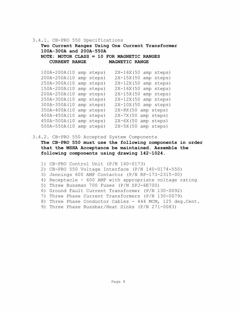
3.4.1. CB-PRO 550 Specifications
Two Current Ranges Using One Current Transformer
100A-300A and 200A-550A
NOTE: MOTOR CLASS = 10 FOR MAGNETIC RANGES
CURRENT RANGE MAGNETIC RANGE
100A-200A(10 amp steps) 2X-16X(50 amp steps)
200A-250A(10 amp steps) 2X-15X(50 amp steps)
250A-300A(10 amp steps) 2X-12X(50 amp steps)
150A-200A(10 amp steps) 2X-16X(50 amp steps)
200A-250A(10 amp steps) 2X-15X(50 amp steps)
250A-300A(10 amp steps) 2X-12X(50 amp steps)
300A-350A(10 amp steps) 2X-10X(50 amp steps)
350A-400A(10 amp steps) 2X-8X(50 amp steps)
400A-450A(10 amp steps) 2X-7X(50 amp steps)
450A-500A(10 amp steps) 2X-6X(50 amp steps)
500A-550A(10 amp steps) 2X-5X(50 amp steps)
3.4.2. CB-PRO 550 Accepted System Components
The CB-PRO 550 must use the following components in order
that the MSHA Acceptance be maintained. Assemble the
following components using drawing 142-1024.
1) CB-PRO Control Unit (P/N 140-0173)
2) CB-PRO 550 Voltage Interface (P/N 140-0174-550)
3) Jennings 600 AMP Contactor (P/N RP-173-2315-00)
4) Receptacle - 600 AMP with appropriate voltage rating
5) Three Bussman 700 Fuses (P/N SPJ-6E700)
6) Ground Fault Current Transformer (P/N 130-0092)
7) Three Phase Current Transformers (P/N 130-0079)
8) Three Phase Conductor Cables - 444 MCM, 125 deg.Cent.
9) Three Phase Bussbar/Heat Sinks (P/N 271-0083)
Page 8

FUSE A
FUSE B
FUSE C
GF
CT
GF
CT
TE
ST
CT A
CT C
CT B
LOAD
AU
X
LINE CONTACTOR
VOLTAGE INTERFACE MODULE
BO
TT
LE
A S
TU
CK
FU
SE
A O
PE
N
BO
TT
LE
B S
TU
CK
FU
SE
B O
PE
N
BO
TT
LE
C S
TU
CK
FU
SE
C O
PE
N
11
5 V
AC
PH
AS
E A
VO
LT
S
PH
AS
E B
VO
LT
S
PH
AS
E C
VO
LT
S
RE
MO
TE
ST
OP
G
ND
MO
N R
EL
A
SO
LE
NO
ID
CT TAP SOLID
STATE SWITCH E
LE
CT
RO
NIC
CO
NT
RO
L U
NIT
PH
AS
E C
CU
RR
EN
T
PH
AS
E B
CU
RR
EN
T
PH
AS
E A
CU
RR
EN
T
AU
X R
EL
AY
SO
LID
ST
AT
E
ST
OP
SW
ITC
H
11
5 V
AC
RE
TU
RN
4 L
INE
X 2
0 C
HA
R L
CD
A
ND
KE
Y P
AD
MIC
RO
PR
OC
ES
SO
R
WA
RN
AL
AR
M
OP
EN
CL
OS
ED
FA
UL
T
BU
ZZ
ER
ST
OP
NO
N-V
OL
AT
ILE
CO
NF
IGU
RA
TIO
N
ME
MO
RY
RS
-48
5 C
OM
M
FAULT
OPEN
RESET
CLOSE
TO
PL
C C
ON
TR
OL
KE
Y
CL
OS
E
PR
OG
RA
M
GF
CT
TE
ST
GF
CT
CU
RR
EN
T R
ET
UR
T
TA
P #
1 C
ON
TR
OL
TA
P #
2 C
ON
TR
OL
TA
P #
3 C
ON
TR
OL
FIGURE 1, CB-PRO BLOCK DIAGRAM Page 9

4. Description
The CB-PRO is composed of four primary components. Refer to
Figure 1, CBPRO Block Diagram. These components consist of the
contactor, fuses, voltage interface module and electronic control
unit. The contactor and fuses for all the configurations of the CB
-PRO are the same as those used in the CB-1000/100/200 series of
circuit breakers. The voltage interface module and electronic
control unit differ from those used in the CB-1000/100/200 design.
4.1. CB-PRO Configurations
The CB-PRO may have five configurations. The configuration is
determined by the continuous current carrying capacity of the
contactor and fuses. The three phase current transformer tap solid
state switch is different for each configuration.
4.1.1. CB-PRO 225
The CB-PRO 225 may be configured to operate over the full load
current range of 10 amperes to 225 amperes. The contactor is a
Joslyn-Clark 320 ampere contactor. The fuse (one for each phase)
is a Bussman 600 ampere fuse. Three current transformers (one for
each phase) and a three phase solid state switch allows the 10 to
225 ampere range to be covered.
4.1.2. CB-PRO 300
The CB-PRO 300 may be configured to operate over the full load
current range of 10 amperes to 300 amperes. The contactor is a
Joslyn-Clark 320 ampere contactor. The fuse (one for each phase)
is a Bussman 600 ampere fuse. Three current transformers (one for
each phase) and a three phase solid state switch allows the 10 to
300 ampere range to be covered.
4.1.3. CB-PRO 450
The CB-PRO 450 may be configured to operate over the full load
current range of 100 amperes to 450 amperes. The contactor is a
ITT Jennings 450 ampere contactor. The fuse (one for each phase)
is a Bussman 600 ampere fuse. Three current transformers (one for
each phase) and a three phase solid state switch allows 100 to 450
ampere range to be covered.
4.1.4. CB-PRO 550
The CB-PRO 550 may be configured to operate over the full load
current range of 100 amperes to 550 amperes. The contactor is a
ITT Jennings 600 ampere contactor. The fuse (one for each phase)
is a Bussman 700 ampere fuse. Three current transformers (one for
each phase) and a three phase solid state switch allows 100 to 550
ampere range to be covered.
Page 10
4.1.5. CB-PRO 800
The CB-PRO 800 may be configured to operate over the full
load current range of 150 amperes to 800 amperes. The
contactor is a Mitsubishi 800 ampere contactor. The fuse (one
for each phase) is a Bussman 1000 ampere fuse. Three current
transformers (one for each phase) and a three phase solid
state switch allows 150 to 800 ampere range to be covered.
4.2. Contactor
The contactor has proven itself to be a reliable device for
controlling power to circuits even in the harsh
environment of the coal mine. The contactor consists of
vacuum bottle interrupters (one for each phase) that are held
closed by applying 115 VAC to a solenoid. The vacuum bottle
interrupters are required to carry the continuous current
defined by the contactor rating and it must also interrupt
fault currents in the 6000 ampere range. The interrupt ratings
of the 320 ampere, 450 ampere, 600 ampere and 800 ampere
contactors are 6000, 6000, 7000 and 13,000 respectively. All
contactor vacuum bottle interrupters are rated for a minimum
of 1500 VAC operation.
When the contactor is in the OPEN condition, the
interrupters are monitored via the voltage interface module to
insure that the interrupter contacts are not stuck. If a
bottle is stuck, the electronic control unit will display a
STUCK BOTTLE FAULT and the contactor is prohibited from
closing. Several control switches (all in series) remove the
115 VAC from the solenoid to open the contactor interrupter
bottles. These are the external cable ground continuity
monitor contacts, the remote control stop switch, the CB-PRO
front panel STOP switch and the CB-PRO solid state switch. An
auxiliary contact that is operated from the same drive
mechanism that operates the vacuum interrupter bottles is
monitored by the microprocessor to confirm that the contactor
is closed when it should be closed. If the contactor fails to
close, the open command is then sent to the contactor
solenoid.
Page 11

4.3. Fuses
Since most power circuits to which the CB-PRO is applied
have an available fault current level higher than the
interrupt rating of the vacuum bottle interrupters, a fuse is
used to increase the the CB-PRO interrupt rating. The fuses
for all configurations of the CB-PRO are 1000 VAC rated, fast
acting and the current limiting type. The fuses are equipped
with buttons that pop out when the fuse is opened due to over
current. The fuses are placed on the load side of the
contactor. A window is placed on the power panel. This allows
easy inspection to insure the fuses are in place. Fuses are
monitored for an open condition via the voltage interface
module to allow the electronic control unit to open the
contactor and display a FUSE OPEN FAULT.
4.4. Contactor and Fuse Open Time Coordination
An important aspect of the operation of the CB-PRO
circuit breaker is the coordination of the opening time of the
fuse and the opening time of the contactor. Not only does the
fuse increase the interrupt rating of the CB-PRO system, it
also protects the vacuum bottle interrupters from clearing a
fault current beyond their rating. In order that the vacuum
bottle interrupters be protected, the fuse must always open
before the contactor attempts to interrupt currents above its
rating. A requirement of the MSHA A&CC design criteria is
that the manufacturer present a worst case analysis of the
opening time of the contactor and the selected fuse. This
analysis is done using the fuse manufacturer's procedure for
determining the fuse’s worst case opening time. Further, a
safety factor of an additional 10% is added. The analysis
must prove the fuse will always open first even at 90%
contactor interrupt rating. Coordination tests are then
performed to prove that the fuse will always open first.
These tests are performed with a nearly resistive source
impedance (97% power factor) to insure a symmetrical fault
current is delivered to the fuse.
Note: See Figures 3 thru 24 for the current vs. open times for
various CB-PRO configurations.
Page 12

4.5. Phase Current Transformers
A current transformer for each phase provides an accurate
voltage output to the electronic control unit. This output
represents the magnitude and phase of the current. The
current transformers are designed to not saturate and thus
provide true linear representation of the phase current over
the full range of CB-PRO operation. This over range
capability insures that high level start-up currents and fault
currents are accurately delivered to the electronic control
unit for processing. Each current transformer output is
connected to a solid state switch assembly that is controlled
by the electronic control unit. This solid state switch
assembly is located in the Voltage Interface Assembly. When
the user configures the CB-PRO for a particular current range,
the correct output from the solid state switch is delivered to
the electronic control unit by tapping the CT output. As the
user selects a higher current range, the solid state switch
taps the CT output even more to provide the correct input to
the electronic control unit. The solid state switch for the CB
-PRO 225 has 3 outputs covering the range of 10 amperes to 225
amperes. The first output tap covers 10 amperes to 30
amperes. The second tap covers 30 amperes to 90 amperes. The
third tap covers 100 amperes to 225 amperes. The solid state
switch for the CB-PRO 300 has 3 outputs covering the range of
10 amperes to 300 amperes. The first output tap covers 10
amperes to 30 amperes. The second tap covers 30 amperes to 90
amperes. The third tap covers 100 amperes to 300 amperes. The
solid state switch for the CB-PRO 450 has 2 outputs covering
the range of 100 amperes to 450 amperes. The first output tap
covers 100 amperes to 300 amperes. The second tap covers 150
amperes to 450 amperes. The solid state switch for the CB-PRO
550 has 2 outputs covering the range of 100 amperes to 550
amperes. The first output tap covers 100 amperes to 300
amperes. The second tap covers 200 amperes to 550 amperes. The
CB-PRO electronic control unit can detect if one or two of the
current transformers are open or disconnected by default since
this would give the appearance of a phase current imbalance.
If this condition exists, the control unit will open the
contactor and display the PHASE CURRENT IMBALANCE fault.
4.6. Ground Fault Current Tranformer
A phase to ground current fault sensing current
transformer is placed around all three phase conductors.
This current transformer provides an output to the Page 13
The current transformer has an additional winding that allows
testing of the ground fault sensing circuitry by the
electronic control unit. The user selects the GROUND FAULT
TEST function on the electronic control unit panel and the
current is injected into the spare winding. The control unit
measures the ground fault current transformer output, opens
the circuit breaker and displays GROUND FAULT on the display.
4.7. Voltage Interface Module
The voltage interface module isolates the high voltage
circuit from the low voltage circuit for the monitored or
measured functions connected to the electronic control unit.
Three phase voltage (480 VAC to 1000 VAC) is stepped-down and
applied to the input of three precision isolation amplifiers
contained in the interface module. The isolated voltage is
then applied to the input of the electronic control unit where
it is processed and available for display. Outputs from each
phase fuse are connected to the voltage interface module.
Opto-couplers measure voltage drop across each fuse. If this
voltage drop is large enough (meaning the fuse is open), this
voltage is transferred across the voltage barrier and
delivered to the electronic control unit. The electronic
control unit opens the circuit breaker and presents the FUSE
OPEN fault on the display. Opto-couplers also measure voltage
between the load side of the contactor and frame ground. If
this voltage is large enough when the contactor is open
(meaning the contactor interrupter is stuck), this voltage
is transferred across the voltage barrier and delivered to the
electronic control unit. The electronic control unit prevents
the circuit breaker from closing and presents the STUCK BOTTLE
fault on the display.
The Voltage Interface Module also houses the current
tranformer tap solid state switch PC board assembly. This
assembly consists of a resistive divider and solid state
switch for each phase to automatically provide the correct
output level to Electronic Control Unit.
Page 14

4.9. Electronic Control Unit(ECU)
The electronic control unit is the processing center for
all the CB-PRO monitor and control functions. The
microprocessor evaluates analog and digital inputs from
transducers, switches and the key pad and provides outputs to
open/close the contactor and update the LCD display. The
firmware that provides the instructions for the microprocessor
is stored in an EPROM. Configuration parameters are stored in
non-volatile memory to retain them when power is removed.
4.9.1. RS-485 Comm
The CB-PRO may be connected to a RS-485 serial interface
communications line to provide monitor and control functions
from a remote Master Station. Both two wire and four wire
interfaces are serviced. Ask about communications protocols
presently serviced.
4.9.2. PLC Monitor and Control
For less demanding monitor and control applications the CB-
PRO may be connected to a PLC. Outputs to the PLC include a
FAULT signal and an OPEN signal. Inputs from the PLC are
FAULT RESET and REMOTE CLOSE.
4.9.3. Three Phase Voltage Measurement
Three AC voltages representing the magnitude and phase of
the three AC line voltages are sampled by high speed analog to
digital converters in the electronic control unit. Both the
RMS and PEAK value of each phase voltage are determined and
made available for LCD display. The phase of voltage is
determined and is used to calculate the phase angle between
voltage and current(power factor). Phase A voltage is used to
synchronize the sampling of all the voltage and current inputs
the electronic control unit. This is done to insure the
sampling occurs at the same time during for each cycle. The
RMS value of each phase voltages is compared to the value
selected during configuration. If the voltage is less by the
under voltage percentage (also selected during configuration),
the electronic control unit will open the contactor and
display the LOW LINE VOLTAGE fault.
4.9.4. Control Voltage Measurement
The control voltage (115 VAC) to power the contactor and
electronic control unit is also monitored by the electronic
control unit. If the voltage drops below 80 VAC the electronic
control unit will open the contactor and display the
Page 15

4.9.5. Three Phase Current Measurement
Three AC currents representing the magnitude and phase of
the three AC load currents are sampled by high speed analog to
digital converters in the electronic control unit. Both the
RMS and PEAK value of each phase current are determined and
made available for LCD display. The phase of each current is
determined and is used to calculate the phase angle between
voltage and current (power factor). The phase angle of each
current with respect to its voltage is available for LCD
display. The PEAK current value for each phase is made
available for LCD display. The PEAK value of each phase
current is compared to the value selected for the magnetic
trip value during configuration. If the PEAK current is
greater than the magnetic trip set value, the electronic
control unit will open the contactor and display the MAGNETIC
OVER CURRENT fault. The RMS value of each phase current is
compared to the thermal trip set value (full load current
value) selected during configuration. If the RMS value exceeds
the thermal trip set value, a timer is started. If the current
remains above the trip set value for a defined time, the
electronic control unit will open the contactor and display
the THERMAL CURRENT fault. The amount of time that the
contactor is allowed to remain closed depends on the ratio of
RMS current value to the magnetic trip set value. The smaller
the ratio, the longer the contactor is allowed to remain
closed. The thermal trip time is defined by a set of curves
for each CB-PRO configuration. The curves also show that the
thermal trip time is dependent on another factor called Motor
Class. Motor Class is a number that defines the amount of
time (in seconds) the CB-PRO will remain closed while an over
current condition that is six times the thermal trip set
point. For example, if the thermal trip set value is 100
amperes, the Motor Class is 10 and the over current value is
600 amperes, the circuit breaker will open in 10 seconds. See
Figures 3 thru 24 for typical curves. During configuration
(using the OVRLD MENU), the 115% Thermal Overload Time is
displayed and selected.
4.9.6. Ground Fault Current Measurement
Ground fault current is measured in the same manner as
phase currents. The RMS value is made available for LCD
display. If the ground fault current value exceeds the ground
fault current trip value defined during configuration,
the electronic control unit will open the contactor and the
GROUND FAULT message will be displayed. The ground Page 16

When the GROUND FAULT TEST menu is selected and the test
initiated, the electronic control unit will deliver a current
to an auxiliary winding on the ground fault current
transformer. This current is measured as if it were a true
phase to ground fault current. The electronic control unit
opens the contactor and and the GROUND FAULT message is
displayed.
4.9.7. Fuse Open Detection
Fuses are monitored for an open condition via the
voltage interface module to allow the electronic control unit
to open the contactor and display a FUSE OPEN fault.
4.9.8. Stuck Bottle Detection
When the contactor is in the OPEN condition, the
interrupters are monitored via the voltage interface module to
insure that the interrupter contacts are not stuck. If a
bottle is stuck, the electronic control unit will display a
STUCK BOTTLE fault and the contactor is prohibited from
closing.
4.9.9. Auxiliary Contact Monitor
An auxiliary contact of the contactor is monitored by the
microprocessor to confirm that the contactor is closed when it
should be closed. If the contactor fails to close, the
electronic control unit removes the close signal from the
contactor solenoid and AUXILIARY CONTACT fault is displayed.
4.9.10. Solid State Switch
The electronic control unit uses two solid state switches
to open and close the contactor. This redundant switch
insures the contactor will open if one switch fails.
4.9.11. Ground Monitor Relay Contact, Remote Stop and Front
Panel Stop Switch
Inputs are provided for a ground monitor relay contact and
remote stop switch. These external inputs and the
electronic control unit front panel stop switch are connected
in series with the contactor solenoid control voltage to
insure that the contactor is opened when any are opened.
In addition, all of the controls are monitored by the
electronic control unit. The electronic control unit will
remove the close signal from the solid state switch if either
of the controls is opened and display the proper fault
message.
Page 17
4.912. Front Panel Controls and Indicators
The CB-PRO front panel controls and indicators have been
selected to provide the user with all the information required
to quickly analyze and control the CB-PRO operation without
being overly complicated. A user friendly menu driven
interface is provided by the four position keypad and a four
line by 20 character LCD display. With a minimum of effort
the user can quickly learn to retrieve information about the
CB-PRO circuit status and perform the configuration of the
CB-PRO.
4.9.12.1. LCD Display
A four line by 20 character LCD display provides
information about the CB-PRO circuit status and configuration.
4.9.12.2. Keypad
A four position keypad along with the LCD display allows
the user to move through the CB-PRO menu tree to gather status
information about the operation and configuration for the
particular circuit requirements to which the unit is applied.
The four keys of the keypad are:
SELECT —-This key is pressed to either select a function
within a particular menu or select another
menu.
UP —-This key is pressed to move the cursor up
within a particular menu or increment a trip
value.
DOWN —-This key is pressed to move the cursor down
within a particular menu or decrement a trip
value.
RETURN —-This key is pressed to return to the previous
menu selected.
4.9.12.3. Close Switch
The electronic control unit close switch is enclosed in a
protective collar to prevent the switch from being depressed
accidentally. In addition, the switch must be held closed for
two seconds before the close sequence begins. The close
sequence consists of an adjustable (0 to 10 second) warning
period before the contactor actually closes. During this
warning period an audible and visual indication is
Page 18

4.9.12.4. Key Switch
A key switch located on the electronic control unit front
panel is provided to allow the user to lock out operation of
the CB-PRO circuit breaker system. In the RUN position of the
switch, the contactor may be closed. In the PGM (PROGRAM)
position, the CB-PRO configuration may be changed. In the
OFF position, the contactor is prohibited from closing.
4.9.12.5. Open Switch
The electronic control unit front panel stop switch is
connected in series with the contactor solenoid control
voltage to insure that the contactor is opened when the stop
switch is pushed. In addition, the front panel stop switch is
monitored by the electronic control unit. The electronic
control unit will remove the close signal from the contactor
solenoid when the stop switch is pushed and the STOP SWITCH
fault message is displayed.
4.9.12.6. LEDS
Five LEDS provide visual indication about the status of the
CB-PRO circuit breaker.
ALARM - This LED is not used.
WARN - This LED is ON when the electronic control unit is
preparing to close the contactor.
CLOSED- This LED is ON when the contactor is closed.
OPEN - This LED is ON when the contactor is open.
FAULT - This LED is ON when the contactor has been opened
due to a fault condition.
4.9.13. Display Menus
The CB-PRO menus are arranged in a tree configuration with
the MAIN MENU at the top. The main menu allows the user to
select either the first page of STATUS information menus or
the first page CONFIGURATION information menus. Each status
page or configuration page contains a listing of more menus
that may be accessed. The following is a listing of the menus
with a functional description.
Page 19
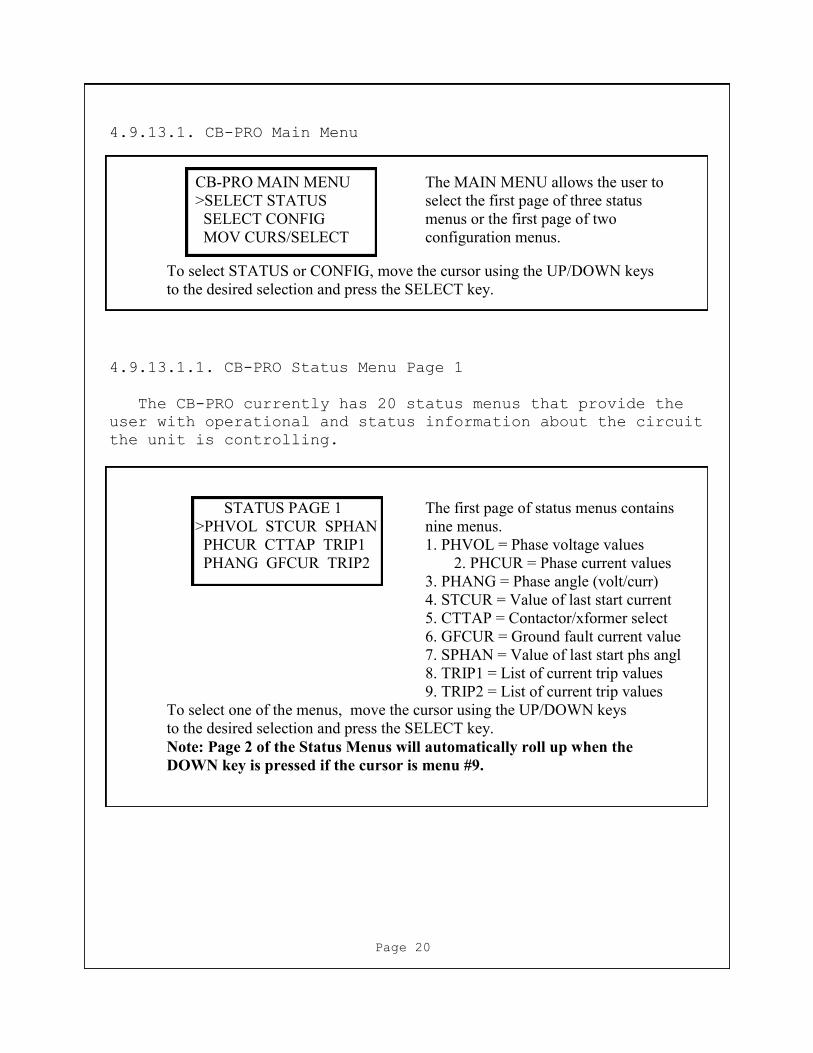
4.9.13.1. CB-PRO Main Menu
CB-PRO MAIN MENU The MAIN MENU allows the user to
>SELECT STATUS select the first page of three status
SELECT CONFIG menus or the first page of two
MOV CURS/SELECT configuration menus.
To select STATUS or CONFIG, move the cursor using the UP/DOWN keys
to the desired selection and press the SELECT key.
4.9.13.1.1. CB-PRO Status Menu Page 1
The CB-PRO currently has 20 status menus that provide the
user with operational and status information about the circuit
the unit is controlling.
STATUS PAGE 1 The first page of status menus contains
>PHVOL STCUR SPHAN nine menus.
PHCUR CTTAP TRIP1 1. PHVOL = Phase voltage values
PHANG GFCUR TRIP2 2. PHCUR = Phase current values
3. PHANG = Phase angle (volt/curr)
4. STCUR = Value of last start current
5. CTTAP = Contactor/xformer select
6. GFCUR = Ground fault current value
7. SPHAN = Value of last start phs angl
8. TRIP1 = List of current trip values
9. TRIP2 = List of current trip values
To select one of the menus, move the cursor using the UP/DOWN keys
to the desired selection and press the SELECT key.
Note: Page 2 of the Status Menus will automatically roll up when the
DOWN key is pressed if the cursor is menu #9.
Page 20

4.9.13.1.2. CB-PRO Phase Voltages Status Menu
PHASE VOLTAGES The Phase Voltages Status Menu
A 0995 RMS/1400 PK displays the RMS and Peak value
B 0995 RMS/1400 PK for each phase voltage. To return to
C 0995 RMS/1400 PK the first page of Status Menus, press
the RETURN key
4.9.13.1.3. CB-PRO Phase Currents Status Menu
PHASE CURRENTS The Phase Currents Status Menu
A 0100 RMS/0140 PK displays the RMS and Peak value
B 0100 RMS/0140 PK for each phase current. To return to
C 0100 RMS/0140 PK the first page of Status Menus, press
the RETURN key.
4.9.13.1.4. CB-PRO Phase Angle Status Menu
VOL/CUR PHASE ANGLE The Phase Angle Menu displays the
A 20 DEGREES LEAD phase angle between the voltage
B 20 DEGREES LEAD with respect to the current. To return to
C 20 DEGREES LEAD the first page of Status Menus, press
the RETURN key.
4.9.13.1.5. CB-PRO Last Start Current Status Menu
LAST START CURRENT The Last Start Menu displays the
A 500 AMP PEAK peak value of the last start current.
B 500 AMP PEAK To return to the first page of Status
C 500 AMP PEAK Menus, press the RETURN key.
4.9.13.1.6. CB-PRO Circuit Configuration Status Menu
CIRCUIT CONFIG The Circuit Confuguration Menu
320 AMP CONTACTOR displays selected contactor size, the
100 TO 300 AMP TAP current transformer tap current range,
OVERLOAD(SEC) 540 and the 115% Overload time in seconds
To return to the first page of the Status
Menus, press the RETURN key.
Page 21

4.9.13.1.7. CB-PRO Ground Fault Current Status Menu
GROUND FLT CURRENT The Ground Fault Current Menu
0.1 AMPERES displays the present value and
HISTORY MAXIMUM historical value of ground fault current.
5.5 AMPERES To return to the first page of Status
Menus, press the RETURN key
4.9.13.1.8. CB-PRO Last Start Phase Angle Status Menu
LAST START PHAS ANG The Last Start Phase Angle Menu
A PHASE 30 DEGREES displays the phase angle between the
B PHASE 30 DEGREES voltage with respect to the current for
C PHASE 30 DEGREES the last motor start. To return to the
first page of Status Menus, press the
RETURN key.
4.9.13.1.9. CB-PRO Trip Settings 1 Status Menu
TRIP SETTINGS 1 The Trip Setting 1 Menu displays the
THERMAL 0100 AMP thermal current trip value, the magnetic
MAGNETIC 0800 AMP current trip value, and the ground fault
GND FAULT 4.00 AMP current trip value. To return to the first
page of Status Menus, press the
RETURN key.
4.9.13.1.10. CB-PRO Trip Settings 2 Status Menu
TRIP SETTINGS 2 The Trip Setting 2 Menu displays the
PHASE CUR IMBAL 30% phase current imbalance trip %, the
UNDER VOLTAGE 30% under voltage trip %, and the trip delay
TRIP DELAY 3.0 SEC for these two faults. To return to the
first page of Status Menus, press the
RETURN key.
Page 22
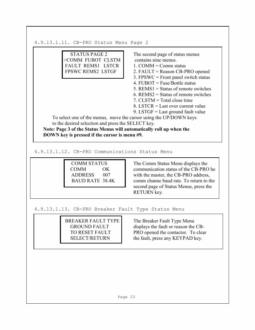
4.9.13.1.11. CB-PRO Status Menu Page 2
STATUS PAGE 2 The second page of status menus
>COMM FUBOT CLSTM contains nine menus.
FAULT REMS1 LSTCR 1. COMM = Comm status
FPSWC REMS2 LSTGF 2. FAULT = Reason CB-PRO opened
3. FPSWC = Front panel switch status
4. FUBOT = Fuse/Bottle status
5. REMS1 = Status of remote switches
6. REMS2 = Status of remote switches
7. CLSTM = Total close time
8. LSTCR = Last over current value
9. LSTGF = Last ground fault value
To select one of the menus, move the cursor using the UP/DOWN keys
to the desired selection and press the SELECT key.
Note: Page 3 of the Status Menus will automatically roll up when the
DOWN key is pressed if the cursor is menu #9.
4.9.13.1.12. CB-PRO Communications Status Menu
COMM STATUS The Comm Status Menu displays the
COMM OK communication status of the CB-PRO he
ADDRESS 007 with the master, the CB-PRO address,
BAUD RATE 38.4K comm channe baud rate. To return to the
second page of Status Menus, press the
RETURN key.
4.9.13.1.13. CB-PRO Breaker Fault Type Status Menu
BREAKER FAULT TYPE The Breaker Fault Type Menu
GROUND FAULT displays the fault or reason the CB-
TO RESET FAULT PRO opened the contactor. To clear
SELECT/RETURN the fault, press any KEYPAD key.
Page 23

4.9.13.1.14. CB-PRO Front Panel Switches Status Menu
FRNT PANL SWIT STAT The Front Panel Switch Status Menu
CLOSE SW OPEN displays the status of the CLOSE push
OPEN SW CLOSED button switch, the OPEN or STOP
KEY SW RUN mushroom switch, and the KEY switch.
To return to the second page of Status
Menus, press the RETURN key.
4.9.13.1.15. CB-PRO Fuse and Contactor Bottle Status Menu
FUSE/BOTTLE STATUS The Fuse/Bottle Status Menu displays
A(FUS OK /BOTL OK ) the condition of the fuse and contactor
B(FUS OK /BOTL OK ) bottle for each phase. To return to the
C)FUS OK /BOTL OK ) second page of Status Menus, press the
RETURN key.
4.9.13.1.16. CB-PRO Remote Control Switches #1 Status Menu
REMOTE CONTROL #1 The Remote Control #1 Status Menu
OPEN SW CLOSED displays the status of the remote open,
RESET SW OPEN reset, and close switches. To return to
CLOSE SW OPEN second page of Status Menus, press the
RETURN key.
4.9.13.1.17. CB-PRO Remote Control Switches #2 Status Menu
REMOTE CONTROL #2 The Remote Control #2 Status Menu
GND MONITOR CLOSED displays the status of the ground
SPARE CLOSED monitor, spare, and auxilliary contacts.
AUX CONTACT CLOSED To return to the second page of Status
Menus, press the RETURN key.
Page 24

4.9.13.1.18. CB-PRO Contactor Close Time Status Menu
TOTAL CLOSE TIME The Close Time Menu displays the
number of hours the contactor has
HOURS 00500.82 been closed. To return to the second
page of Status Menus, press the
RETURN key.
4.9.13.1.19. CB-PRO Last Overcurrent Status Menu
LAST OVR CUR #0 ^ The Last Over Current Status Menu
MO/DA/YR HR:MN:SC displays the date, time, and value
10 21 98 16 04 43 of the last FIVE over current conditions
VALUE 01292 AMP that opened the CB-PRO contactor. To
display all FIVE over current dates, times,
and values; press the UP key. TO return to the second page of Status Menus, press the
RETURN key.
4.9.13.1.20. CB-PRO Last Ground Fault Current Status Menu
LAST GND FLT #0 ^ The Last Ground Fault Status Menu
MO/DA/YR HR:MN:SC displays the date, time, and value
10 16 98 10 03 43 of the last FIVE ground fault conditions
VALUE 08.2 AMP that opened the CB-PRO contactor. To
display all FIVE ground fault current
dates, times, and values; press the UP key. TO return to the second page of Status
Menus, press the RETURN key.
Page 25
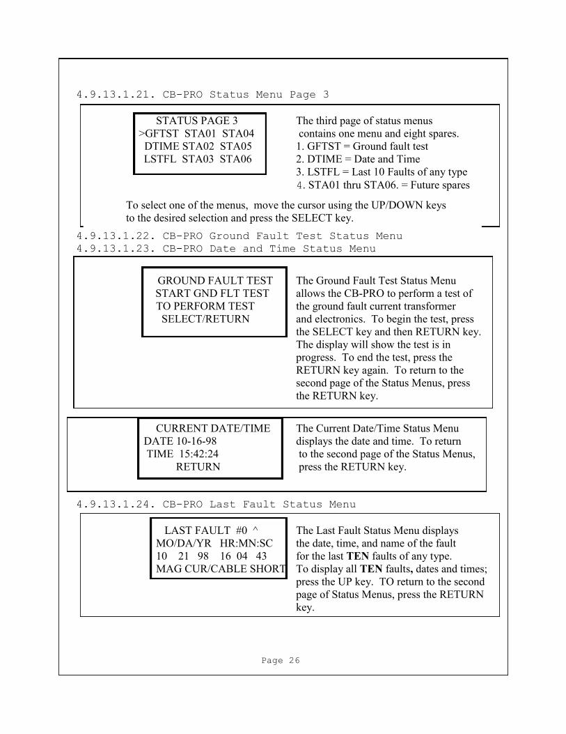
4.9.13.1.21. CB-PRO Status Menu Page 3
STATUS PAGE 3 The third page of status menus
>GFTST STA01 STA04 contains one menu and eight spares.
DTIME STA02 STA05 1. GFTST = Ground fault test
LSTFL STA03 STA06 2. DTIME = Date and Time
3. LSTFL = Last 10 Faults of any type
4. STA01 thru STA06. = Future spares
4.9.13.1.22. CB-PRO Ground Fault Test Status Menu
4.9.13.1.23. CB-PRO Date and Time Status Menu
CURRENT DATE/TIME The Current Date/Time Status Menu
DATE 10-16-98 displays the date and time. To return
TIME 15:42:24 to the second page of the Status Menus,
RETURN press the RETURN key.
4.9.13.1.24. CB-PRO Last Fault Status Menu
LAST FAULT #0 ^ The Last Fault Status Menu displays
MO/DA/YR HR:MN:SC the date, time, and name of the fault
10 21 98 16 04 43 for the last TEN faults of any type.
MAG CUR/CABLE SHORT To display all TEN faults, dates and times;
press the UP key. TO return to the second
page of Status Menus, press the RETURN
key.
To select one of the menus, move the cursor using the UP/DOWN keys
to the desired selection and press the SELECT key.
GROUND FAULT TEST The Ground Fault Test Status Menu
START GND FLT TEST allows the CB-PRO to perform a test of
TO PERFORM TEST the ground fault current transformer
SELECT/RETURN and electronics. To begin the test, press
the SELECT key and then RETURN key.
The display will show the test is in
progress. To end the test, press the
RETURN key again. To return to the
second page of the Status Menus, press
the RETURN key.
Page 26

4.9.13.2. CB-PRO Configuration Menus
To begin the configuration process of the CB-PRO use the
MAIN MENU and move the cursor to SELECT CONFIG. Press the
SELECT key and the PASS CODE MENU will be displayed.
NOTE: The front panel KEY switch must be in the
program (PGM)position before the CB-PRO will
allow configuration changes.
4.9.13.2.2. CB-PRO Enter Pass Code Configuration Menu
ENTER PASS CODE This menu is used to enter the
0123456789 passcode before access to the
^ (ENTRY 1) configuration menus or changing
INC/DEC/SELECT/RETN the passcode is allowed.
The passcode consists of four numbers that are entered by moving the cursor (^) to each
number using the INC/DEC keys and pressing the SELECT key. As each number is
selected, the ENTRY number is incremented. When the fourth number is entered, press the
SELECT key again. If the four numbers that were entered are the same as the passcode,
page 1 of the configuration menus will be displayed or the CHANGE PASS CODE menu
will be displayed. To return to the PASS CODE MENU, press the RETURN key.
4.9.13.2.1. CB-PRO Enter/Change Pass Code Configuration Menu
PASS CODE MENU This menu is displayed when the
> ENTER PASSCODE configuration series of menus is selected
CHANGE PASSCODE from the MAIN MENU. This menu
INC/DEC/SELECT/RETN allows the user to enter the passcode so
that the configuration menus may be
accessed or the pass code may be changed. If the CHANGE PASSCODE selection is made,
the user must first enter the current passcode before the passcode may be changed. Use the
INC/DEC keys to move the cursor. Press the SELECT key to make the selection. To
return to the second page of Config Menus, press the RETURN key.
Page 27

4.9.13.2.3. CB-PRO Change Pass Code Configuration Menu
CHANGE PASS CODE This menu is used to change the
0123456789 passcode. The passcode consists of four
^ (ENTRY 1) numbers that are entered by moving the
INC/DEC/SELECT/RETN cursor (^) to each number using the
INC/DEC keys and pressing the
SELECT key. As each number is selected, the ENTRY number is incremented. When the
four numbers are entered, press the SELECT key again. The passcode is now saved. To
return to the PASS CODE MENU, press the RETURN key.
4.9.13.2.4. CB-PRO Configuration Menu Page 1
The CB-PRO currently has 16 configuration menus that allow the
user to configure the CB-PRO to the circuit the unit is
controlling.
CONFIG PAGE 1 The first page of configuration contains
>CRXFM COMM MAGTP nine menus.
ZROCT GFTRP IMBAL 1. CRXFM = Select contactor/xformer
OVRLD THRTP UNVOL 2. ZROCT = Calibrate CT’s
3. OVRLD = Selects overload time
4. COMM = Configure comm port
5. GFTRP = Set Gnd Fault trip level
6. THRTP = Set thermal current trip
7. MAGTP = Set magnet current trip
8. IMBAL = Set % current imbal trip
9. UNVOL = Set % phase volt trip
To select one of the menus, move the cursor using the UP/DOWN keys to the desired
selection and press the SELECT key.
Note: Page 2 of the Config Menus will automatically roll up when the
DOWN key is pressed if the cursor is menu #9.
Page 28
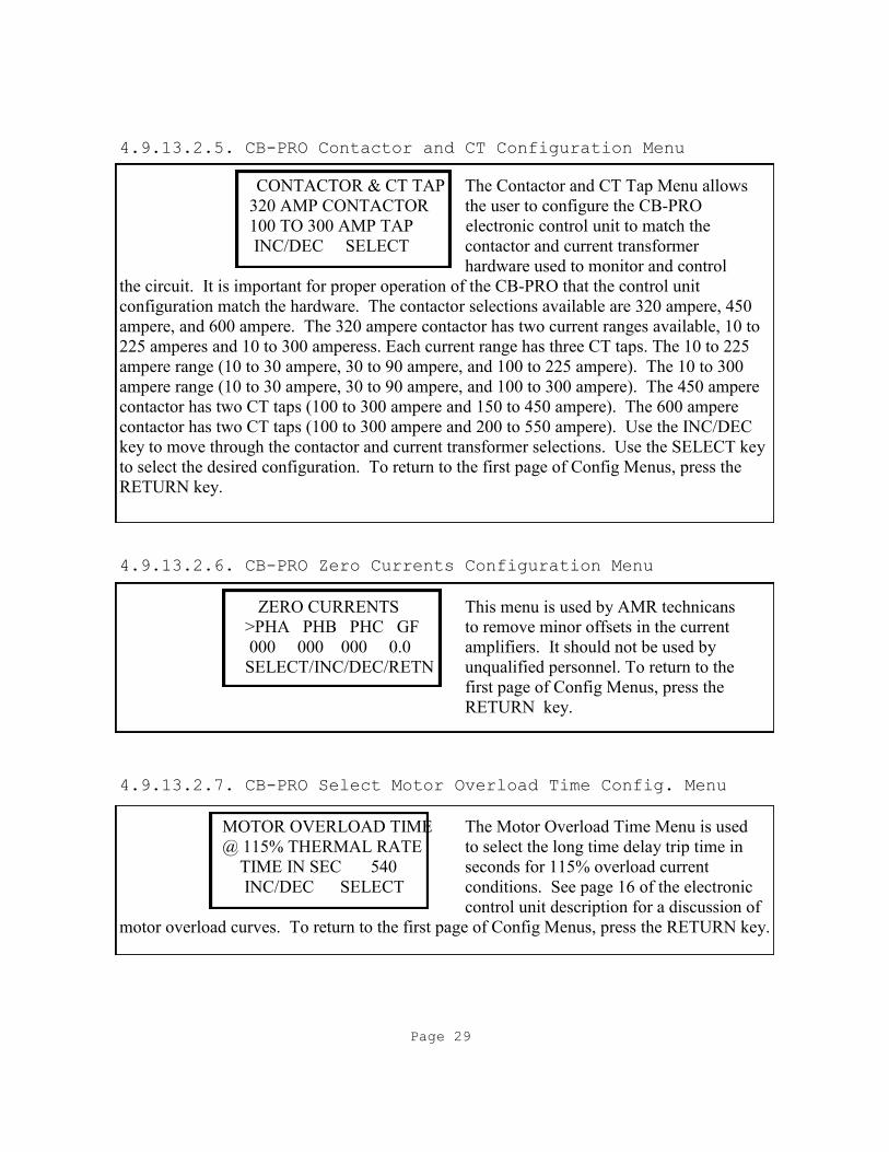
4.9.13.2.5. CB-PRO Contactor and CT Configuration Menu
CONTACTOR & CT TAP The Contactor and CT Tap Menu allows
320 AMP CONTACTOR the user to configure the CB-PRO
100 TO 300 AMP TAP electronic control unit to match the
INC/DEC SELECT contactor and current transformer
hardware used to monitor and control
the circuit. It is important for proper operation of the CB-PRO that the control unit
configuration match the hardware. The contactor selections available are 320 ampere, 450
ampere, and 600 ampere. The 320 ampere contactor has two current ranges available, 10 to
225 amperes and 10 to 300 amperess. Each current range has three CT taps. The 10 to 225
ampere range (10 to 30 ampere, 30 to 90 ampere, and 100 to 225 ampere). The 10 to 300
ampere range (10 to 30 ampere, 30 to 90 ampere, and 100 to 300 ampere). The 450 ampere
contactor has two CT taps (100 to 300 ampere and 150 to 450 ampere). The 600 ampere
contactor has two CT taps (100 to 300 ampere and 200 to 550 ampere). Use the INC/DEC
key to move through the contactor and current transformer selections. Use the SELECT key
to select the desired configuration. To return to the first page of Config Menus, press the
RETURN key.
4.9.13.2.6. CB-PRO Zero Currents Configuration Menu
ZERO CURRENTS This menu is used by AMR technicans
>PHA PHB PHC GF to remove minor offsets in the current
000 000 000 0.0 amplifiers. It should not be used by
SELECT/INC/DEC/RETN unqualified personnel. To return to the
first page of Config Menus, press the
RETURN key.
4.9.13.2.7. CB-PRO Select Motor Overload Time Config. Menu
MOTOR OVERLOAD TIME The Motor Overload Time Menu is used
@ 115% THERMAL RATE to select the long time delay trip time in
TIME IN SEC 540 seconds for 115% overload current
INC/DEC SELECT conditions. See page 16 of the electronic
control unit description for a discussion of
motor overload curves. To return to the first page of Config Menus, press the RETURN key.
Page 29

4.9.13.2.8. CB-PRO Communications Configuration Menu
COMMUNICATIONS The Communications Config Menu
>BAUD 38.4K ENAB NO allows the electronic control unit to
ADDRESS 008 be configured as a monitor system
CURSR INC/DEC SELET remote. Data that is displayed on the
CB-PRO front panel is sent to a mine
monitoring system master station over the RS-485 communication link. To select the baud
rate, address, or enable the CB-PRO: move the cursor to the desire function by using the
INC/DEC keys and then press the SELECT key. After the function has been selected, use
the INC/DEC key to toggle the baud rate between 4800 and 38400 baud, enable or disable
communicatons, or change the address. After the function change has occurred, use the
SELECT key to save the change. To return to the first page of Config Menus, press the
RETURN key.
4.9.13.2.9. CB-PRO Set Ground Fault Current Trip Config Menu
GROUND FAULT TRIP The Ground Fault Trip Menu allows the
user to set the ground fault trip current
4.0 AMPS between 1.0 amperes and 25 amperes
INC/DEC SELECT in 0.1 ampere increments. Use the
INC/DEC key to change the display to the
desired current value. Use the SELECT key to save the value. To return to the first page of
Config Menus, press the RETURN key.
4.9.13.2.10. CB-PRO Set Thermal Current Trip Config Menu
THERMAL TRIPSET The Thermal Tripset Menu is used to
set the full load or thermal current value
100 AMPS that provides thermal over load
INC/DEC SELECT protection for the circuit controlled
by the CB-PRO. Use the INC/DEC key to
change the display to the desired value. Use the SELECT key to save the value. To return
to the first page of Config Menus, press the RETURN key.
Page 30
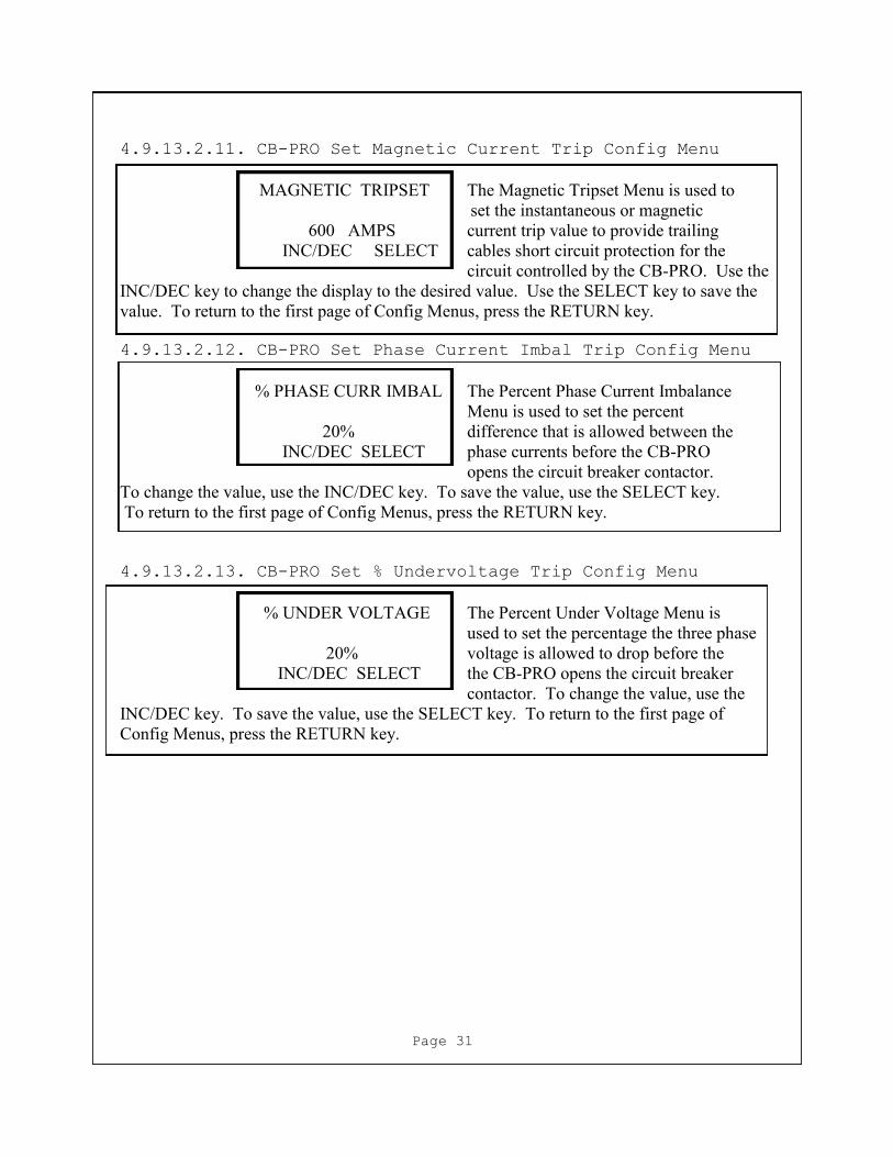
4.9.13.2.11. CB-PRO Set Magnetic Current Trip Config Menu
MAGNETIC TRIPSET The Magnetic Tripset Menu is used to
set the instantaneous or magnetic
600 AMPS current trip value to provide trailing
INC/DEC SELECT cables short circuit protection for the
circuit controlled by the CB-PRO. Use the
INC/DEC key to change the display to the desired value. Use the SELECT key to save the
value. To return to the first page of Config Menus, press the RETURN key.
4.9.13.2.12. CB-PRO Set Phase Current Imbal Trip Config Menu
% PHASE CURR IMBAL The Percent Phase Current Imbalance
Menu is used to set the percent
20% difference that is allowed between the
INC/DEC SELECT phase currents before the CB-PRO
opens the circuit breaker contactor.
To change the value, use the INC/DEC key. To save the value, use the SELECT key.
To return to the first page of Config Menus, press the RETURN key.
4.9.13.2.13. CB-PRO Set % Undervoltage Trip Config Menu
% UNDER VOLTAGE The Percent Under Voltage Menu is
used to set the percentage the three phase
20% voltage is allowed to drop before the
INC/DEC SELECT the CB-PRO opens the circuit breaker
contactor. To change the value, use the
INC/DEC key. To save the value, use the SELECT key. To return to the first page of
Config Menus, press the RETURN key.
Page 31
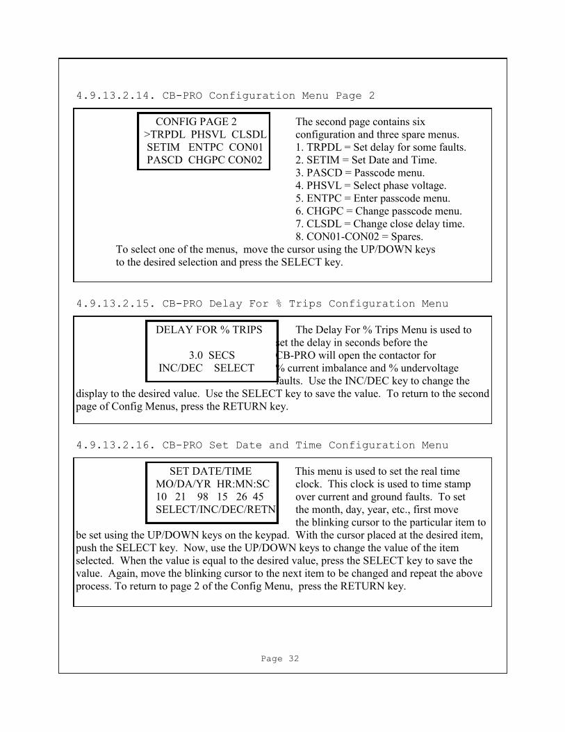
4.9.13.2.14. CB-PRO Configuration Menu Page 2
CONFIG PAGE 2 The second page contains six
>TRPDL PHSVL CLSDL configuration and three spare menus.
SETIM ENTPC CON01 1. TRPDL = Set delay for some faults.
PASCD CHGPC CON02 2. SETIM = Set Date and Time.
3. PASCD = Passcode menu.
4. PHSVL = Select phase voltage.
5. ENTPC = Enter passcode menu.
6. CHGPC = Change passcode menu.
7. CLSDL = Change close delay time.
8. CON01-CON02 = Spares.
To select one of the menus, move the cursor using the UP/DOWN keys
to the desired selection and press the SELECT key.
4.9.13.2.15. CB-PRO Delay For % Trips Configuration Menu
DELAY FOR % TRIPS The Delay For % Trips Menu is used to
set the delay in seconds before the
3.0 SECS CB-PRO will open the contactor for
INC/DEC SELECT % current imbalance and % undervoltage
faults. Use the INC/DEC key to change the
display to the desired value. Use the SELECT key to save the value. To return to the second
page of Config Menus, press the RETURN key.
4.9.13.2.16. CB-PRO Set Date and Time Configuration Menu
SET DATE/TIME This menu is used to set the real time
MO/DA/YR HR:MN:SC clock. This clock is used to time stamp
10 21 98 15 26 45 over current and ground faults. To set
SELECT/INC/DEC/RETN the month, day, year, etc., first move
the blinking cursor to the particular item to
be set using the UP/DOWN keys on the keypad. With the cursor placed at the desired item,
push the SELECT key. Now, use the UP/DOWN keys to change the value of the item
selected. When the value is equal to the desired value, press the SELECT key to save the
value. Again, move the blinking cursor to the next item to be changed and repeat the above
process. To return to page 2 of the Config Menu, press the RETURN key.
Page 32
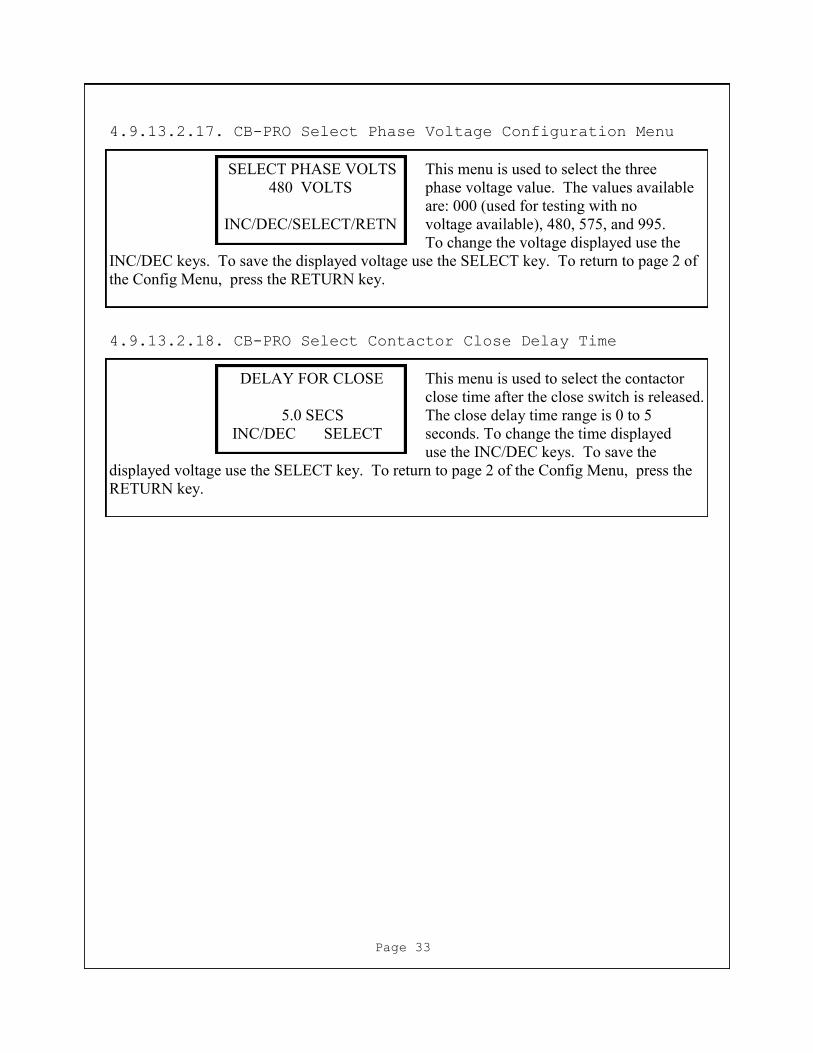
4.9.13.2.17. CB-PRO Select Phase Voltage Configuration Menu
SELECT PHASE VOLTS This menu is used to select the three
480 VOLTS phase voltage value. The values available
are: 000 (used for testing with no
INC/DEC/SELECT/RETN voltage available), 480, 575, and 995.
To change the voltage displayed use the
INC/DEC keys. To save the displayed voltage use the SELECT key. To return to page 2 of
the Config Menu, press the RETURN key.
Page 33
4.9.13.2.18. CB-PRO Select Contactor Close Delay Time
DELAY FOR CLOSE This menu is used to select the contactor
close time after the close switch is released.
5.0 SECS The close delay time range is 0 to 5
INC/DEC SELECT seconds. To change the time displayed
use the INC/DEC keys. To save the
displayed voltage use the SELECT key. To return to page 2 of the Config Menu, press the
RETURN key.

5. Operation
5.1. Fuse/Contactor Fault Disconnect Coordination
Since the vacuum contactor is limited to disconnecting
faults that are less than its interrupt rating (usually
between 5000 and 7000 amperes), coordination of the disconnect
time between the vacuum bottles and the fuses is crucial to
the protection of the vacuum bottles and the prevention of
nuisance fuse disconnects. The CB-PRO Electronic Control Unit
is designed to always open the vacuum bottle contactor before
the fuses open for faults less than the contactor interrupt
rating. Fault currents above the interrupt rating of the
contactor generate a fuse disconnect time that is faster than
the contactor opening time, thus protecting the vacuum
contactor bottles. Figures 3 thru 24 show the coordination of
the disconnect times between the fuses and vacuum bottle
contactor for various full load current and fault current
conditions.
5.2. CB-PRO Configuration
Before closing the CB-PRO contactor for the first time, the
Electronic Control Unit should be configured to match the
contactor being used and also be configured to match the
particular circuit protection parameters to which the CB-PRO
is being applied. Follow the steps below to configure the
CB-PRO:
Use the Contactor and CT Tap Configuration Menu to select
either the 320,450, 600 or 800 amp contactor that is
being controlled by the CB-PRO Electronic Control Unit.
Use the Contactor and CT Tap Configuration Menu to select
the current transformer tap range that matches the
continuous or full load current of the circuit the CB-PRO
circuit breaker is protecting.
Use the Motor Overload Menu to select the thermal trip
time in seconds the CB-PRO Electronic Control Unit will
open the contactor for an overload current that is
115% of the thermal trip setting.
NOTE: This value is usually set to 540 seconds.
Use the Communications Menu to set the CB-PRO baud rate
and address. Page 34
Use the Ground Fault Trip Menu to set the Ground Fault
Trip level.
Use the Thermal Tripset Menu to set the circuit full
load current value.
Use the Magnetic Tripset Menu to set the instantaneous
current trip value.
Use the % Phase Current Imbalance Menu to set the percent
current imbalance value. NOTE: Usually set to 30%.
Use the % Under Voltage Menu to set the percent under
voltage value. NOTE: Usually set to 30%.
Use the Delay For % Trips Menu to set the delay in
seconds for the percent current imbalance and under
voltage faults. NOTE: Usually set to 3.
Use the Select Phase Volage Menu to select the three phase
voltage value that matches the circuit voltage.
Use the Close Delay Time Menu to select the time between
the release of the Close Switch and the contactor closing.
5.3. Using Status Menus to Confirm Configuration
Any time the configuration of the CB-PRO has been changed
the changes should be verified by using the appropriate
Status Menus.
Use the Circuit Config Status Menu to verify the
contactor type, current transformer tap and overload time
selected.
Use the Trip Settings #1 Menu to verify the full load
(thermal) current, instantaneous (magnetic) current and
ground fault current trip settings.
Use the Trip Settings #2 Menu to verify the phase current
imbalance percent, undervoltage percent and trip delay
settings.
Page 35

5.4. Reset of Faults
When the CB-PRO Electronic Control Unit detects a fault
condition, it causes the contactor to open. The Breaker Fault
Type Menu immediately appears on the LCD display and the Fault
LED is turned ON. To close the contactor after a fault has
been detected, the fault must first be cleared. To clear a
fault with the Breaker Fault Type Menu displayed, press any of
the four keys on the keypad. The fault LED will extinguish and
the contactor may now be closed. If the Fault LED is ON and
the Breaker Fault Type Menu is not displayed, then the Breaker
Fault Type Menu must first be displayed by selecting it from
the Status Menus Page 2 menu.
5.5. Closing the Contactor
To close the contactor the Electronic Control Unit Fault
LED must first be OFF. See section 5.4. Reset of Faults.
Push the Electronic Control Unit Front Panel Close Switch and
hold for approximately 2 seconds until the Audible Alarm and
Warn LED come ON. The Electronic Control Unit will execute a
Pre-Close Warning for the length of the delay close time
selectd (0 to 10 seconds)and then close the contactor.
5.6. Caution
If the Stuck Bottle Fault or the Fuse Open Fault is
displayed, be sure to lock out the circuit and turn OFF the
incoming power to the power center before troubleshooting the
power center. Turn OFF the incoming power center power before
checking or changing fuses.
Page 36
6. Installation
The CB-PRO Circuit Breaker System is MSHA accepted as a “no
less effective device” compared to the traditional molded case
circuit breaker. The acceptance and performance of the the
CB-PRO as a circuit interrupting and protection device is
predicated on the proper installation of all components of the
circuit breaker system. Below is a list of components for each
of the CB-PRO Circuit Breaker Systems.
6.1.CB-PRO 225 and CB-PRO 300 Components
Electronic Control Unit Assembly—(140-0173)
Voltage Interface Assembly—(140-0174-300)
CT Tap Solid State Switch PCB Assembly—(253-0339-300)
Contactor—(280-0070)Joslyn-Clark VC77U03515 320 AMP
Fuse—(160-0029)Bussman SPJ-6E600 600 AMP
Phase Current Transformer—(130-0079)
Ground Fault Transformer—(130-0092)
Optional Communications PCB Assembly—(253-0325)
Three Phase Power Cable
CB-PRO 225 1/0 or larger, 90 deg, C.
CB-PRO 300 4/0 or larger, 90 deg. C.
Fuse Heat Sink—None Required
Fuse Insulator (P/N 125-0151)
6.1.1. CB-PRO 225 and CB-PRO 300 Power Components Connection
Refer to Figure 2, CB-PRO Interconnect Diagram. The
contactor for the CB-PRO may be placed on the back of a
standard, removable power center panel using the
available mounting holes. If it is desired to install the
system in the power center excluding the removable power
panel, then mount the contactor on the bottom of the power
center close to the power output receptacle so as to
minimize power cable length from the contactor to the
receptacle.
Use the appropriate three phase power cable as defined
above to make connections from the three phase power buss
to the contactor line side. Before tightening the
contactor line side cable hardware, attach an appropriate
length of #16 AWG, 1000 Volt Rated wire to each contactor
line side terminal. The wire length should be sufficient
to reach from each fuse to the Voltage Interface Module.
These wires will be used to monitor the three Page 37

Install the appropriate three phase power circuit fuses as
defined above on the load side of the contactor.
NOTE: The fuses must be mounted such that they are
clearly visable through a window mounted on the power
center panel. Before tightening the fuse mounting
hardware, attach an appropriate length of #16 AWG, 1000
Volt Rated wire to each fuse terminal. The wire length
should be sufficient to reach from each fuse to the
Voltage Interface Module. These wires will be used to
monitor for open fuse and stuck bottle conditions.
Use the appropriate three phase power cable as defined
above to make connections from the load side of each
fuse to the power receptacle. Place a phase current
transformer around each phase conductor on the load side
and place a ground fault current transformer on the load
side around all three phase conductors before tighting
the cable/fuse/contactor/receptacle hardware.
6.2.CB-PRO 450 Components
Electronic Control Unit Assembly—(140-0173)
Voltage Interface Assembly—(140-0174-450)
CT Tap Solid State Switch PCB Assembly—(253-0339-450)
Contactor—(280-0004)ITT Jennings RP133-2335-00 450 AMP
Fuse—(160-0029)Bussman SPJ6E600 600 AMP
Phase Current Transformer—(130-0079)
Ground Fault Transformer—(130-0092)
Optional Communications PCB Assembly—(253-0325)
Three Phase Power Cable—444 MCM or larger, 125 deg.C.
Fuse Heat Sink—(125-0207)
Buss Bar (125-0203)
6.2.1. CB-PRO 450 Power Components Connection
Refer to Figure 2, CB-PRO Interconnect Diagram. The
contactor for the CB-PRO 450 may be placed on the back of
a standard, removable power center panel using the
available mounting holes. If it is desired to install the
system in the power center excluding the removable power
panel, then mount the contactor on the bottom of the power
center close to the power output receptacle so as to
minimize power cable length from the contactor to the
receptacle.
Page 38

Use the appropriate three phase power cable as defined
above to make connections from the three phase power buss
to the contactor line side. Before tightening the
contactor line side cable hardware, attach an appropriate
length of #16 AWG, 1000 Volt Rated wire to each contactor
line side terminal. The wire length should be sufficient
to reach from each fuse to the Voltage Interface Module.
These wires will be used to monitor the three phase
voltages.
Install the three phase buss bars defined in the CB-PRO
450 Components list. The buss bars are necessary and are
required to maintain the MSHA acceptance of the CB-PRO
450 Circuit Breaker System. They serve to seperate the
fuses to improve voltage-breakdown and they assist in
removing heat from the fuses.
Install the appropriate three phase power circuit fuses
defined above on the top of each phase buss bar.
NOTE: The fuses must be mounted as such so that they are
clearly visable through a window mounted on the power
center panel.Place the heat sink (125-0207) on top of
each fuse terminal (side nearest the load side of the
contactor). Before tightening the fuse mounting hardware,
attach an appropriate length of #16 AWG, 1000 Volt Rated
wire to each fuse terminal. The wire length should be
sufficient to reach from each fuse to the Voltage
Interface Module. These wires will be used to monitor for
open fuse and stuck bottle conditions.
6.3.CB-PRO 550 Components
Electronic Control Unit Assembly—(140-0173)
Voltage Interface Assembly—(140-0174-550)
CT Tap Solid State Switch PCB Assembly—(253-0339-550)
Contactor—(280-0087) ITT Jennings RP173-2315-00 600 AMP
Fuse—(160-0022)Bussman SPJ-6E700 700 AMP
Phase Current Transformer—(130-0079)
Ground Fault Transformer—(130-0092)
Optional Communications PCB Assembly—(253-0325)
Three Phase Power Cable—444 MCM or larger, 125 deg.C.
Fuse Heat Sink—(271-0083)
Page 39
6.3.1. CB-PRO 550 Power Components Connection
Refer to Figure 2, CB-PRO Interconnect Diagram. Because the
contactor for the CB-PRO 550 is too large and heavy to
be placed on the back of a standard, removable power
center panel, the contactor should be mounted in the
bottom of the power center close to the power output
receptacle. This will minimize power cable length from the
contactor to the receptacle.
Use the appropriate three phase power cable as defined
above to make connections from the three phase power buss
to the contactor line side. Before tightening the
contactor line side cable hardware, attach an appropriate
length of #16 AWG, 1000 Volt Rated wire to each contactor
line side terminal. The wire length should be sufficient
to reach from each fuse to the Voltage Interface Module.
These wires will be used to monitor the three phase
voltages.
Place the heat sink (271-0083) on each phase of the load
side of the contactor.
Install the appropriate three phase power circuit fuses
defined above on the top of each phase buss bar.
NOTE: The fuses must be mounted as such so that they are
clearly visable through a window mounted on the power
center panel. Before tightening the fuse mounting
hardware, attach an appropriate length of #16 AWG, 1000
Volt Rated wire to each fuse terminal. The wire length
should be sufficient to reach from each fuse to the
Voltage Interface Module. These wires will be used to
monitor for open fuse and stuck bottle conditions.
6.4.CB-PRO Monitor and Control Components Connection
Place the Voltage Interface Assembly near the contactor too
minimize the wire length between the power line
connections and the Voltage Interface Assembly.
Install the Electronic Control Unit on the power center
panel such that the user will have easy access to all
indicators and controls.
Page 40

Connect the three wires attached to the contactor line
side terminals (used to monitor of all three phase
voltages) to the Voltage Interface Assembly TB1
positions 1 through 3 (phase A to 1, phase B to 2,
phase C to 3).
Connect phase A fuse wires (used to monitor open fuse
and stuck contactor bottle) to the Voltage Interface
Assembly TB2 positions 1 and 2. Connect the wire attached
to the contactor load side of the fuse terminal to TB2-1
and the wire attached to load side of the fuse terminal to
TB2-2.
Connect phase B fuse wires (used to monitor open fuse
and stuck contactor bottle) to the Voltage Interface
Assembly TB2 positions 3 and 4. Connect the wire attached
to the contactor load side of the fuse terminal to TB2-3
and the wire attached to load side of the fuse terminal to
TB2-4.
Connect phase C fuse wires (used to monitor open fuse
and stuck contactor bottle) to the Voltage Interface
Assembly TB2 positions 5 and 6. Connect the wire attached
to the contactor load side of the fuse terminal to TB2-5
and the wire attached to load side of the fuse terminal to
TB2-6.
Connect a #16 AWG wire from an appropriate frame ground
connection on the contactor to the Voltage Interface
Assembly TB2-7.
Connect phase A current transformer output wires to the CT
Tap Solid State Switch (mounted in the Voltage
Interface Assembly) connector J2-11 and 12.
Connect phase B current transformer output wires to the CT
Tap Solid State Switch (mounted in the Voltage
Interface Assembly) connector J2-7 and 8.
Connect phase C current transformer output wires to the CT
Tap Solid State Switch (mounted in the Voltage
Interface Assembly) connector J2-2 and 3.
Page 41

Connect ground fault current transformer test input wires
(#20 AWG White) to the Electronic Control Unit connector
P2-8 and P2-9 positions.
Use a wire of size #16 AWG thru #20 AWG to connect the CT
Tap Solid State Switch connector J2 to the Electronic
Control Unit connectors P1 and P2 as follows:
From CT Tap Solid State Switch to Electronic Control Unit
J2-13————————————————————————-P1-5
J2-9————————————————————————--P1-6
J2-4————————————————————————--P1-7
J2-5—————————————————————————-P1-8
J2-10————————————————————————-P1-9
J2-6————————————————————————--P1-10
J2-1—————————————————————————-P2-3
Use wires of size #16 AWG thru #20 AWG to connect the
Voltage Interface Module connector J1 to the Electronic
Control Unit connectors P1 and P4 as follows:
From Voltage Interface Module to Electronic Control Unit
J1-5—————————————————————————-P1-1
J1-4————————————————————————--P1-2
J1-3————————————————————————--P1-3
J1-10————————————————————————-P4-1
J1-11————————————————————————-P4-2
J1-9————————————————————————--P4-3
J1-8-—————————————————————————P4-4
J1-7——————————————————————-——-P4-5
J1-6————————————————————————--P4-6
J1-1————————————————————————--P4-7
From Voltage Interface Module to Solid State Switch
J1-2—————————————————————————-J2-5
Use a #16 AWG Black wire to connect 115 VAC Line to the
Electronic Control Unit connector position P2-5.
Use a #16 AWG White wire to connect 115 VAC Return to the
Electronic Control Unit connector position P2-6.
Use a #16 AWG Green wire to connect Frame Ground to the
Page 42
Use a #16 AWG White wire to connect the return side of
the contactor control diode bridge to the Electronic
Control Unit connector position P3-10.
Use a #16 AWG White wire to connect 115 VAC Return to one
side of the Ground Monitor Relay normally open contact.
Use a #16 AWG White wire to connect 115 VAC Return to
the Electronic Control Unit connector position P3-6.
Use a #16 AWG White wire to connect the other side of the
Ground Monitor Relay normally open contact to the
Electronic Control Unit connector position P3-7.
If a Remote Stop Switch is used to open the CB-PRO
Circuit Breaker System, use #16 AWG White wire to connect
the stop switch to the Electronic Control Unit connector
posistions P3-7 and P3-8.
If a Remote Stop Switch is not used, use a #16 AWG White
wire to jumper the Electronic Control Unit connector
positions P3-7 to P3-8.
Use a #16 AWG White wire to jumper the Electronic Control
Unit connector positions P3-1 to P3-9.
Use a pair of #16 AWG White wires to connect a set of
contactor normally open auxiliary contacts to the
Electronic Control Unit connector positions P3-2 to P3-3.
The CB-PRO may also be opened using a set of dry,
normally open contacts connected to the Spare Contact
inputs of the Electronic Control Unit connector positions
P3-4 and P3-5.
Use a #16 AWG Green wire to connect the contactor frame
ground to the power center frame ground.
To provide a Fault output to a PLC (0 to 5VDC) connect
the PLC to the Electronic Control Unit connector
position P4-9.
Page 43
To remotely Reset Faults and Remotely Close the CB-PRO
from a PLC, the PLC must provide outputs of 0 to 5VDC.
Connect the PLC RESET/CLOSE RETURN to the Electronic
Control Unit connector position P5-10. Connect the PLC
CLOSE output to the Electronic Control Unit connector
position P5-9. Connect the PLC RESEToutput to the
Electronic Control Unit connector position P5-8.
If used, connect the 2-wire RS-485 communications (+)
wire to the Electronic Control Unit connector position P5
-1. Connect 2-wire RS-485 communications (-) wire to the
Electronic Control Unit connector position P5-2.
Page 44

7. Troubleshooting
7.1. CB-PRO LCD Fault Menu Display Message
Use the CB-PRO LCD display Fault Menu Message as an
indication of the reason the CB-PRO Electronic Control Unit
caused the contactor to open. Note: ECU means Electronic
Control Unit.
FAULT MENU MESSAGE DESCRIPTION OF MESSAGE
A BOTTLE STUCK Phase A contactor bottle is stuck.
A FUSE OPEN Phase A fuse is open.
AUX CONTACT OPEN The contactor has failed to close or stay closed.
B BOTTLE STUCK Phase B contactor bottle is stuck.
B FUSE OPEN Phase B Fuse is open.
BREAKER FAULT RESET The fault has been reset.
C BOTTLE STUCK Phase C contactor bottle is stuck.
C FUSE OPEN Phase C fuse is open
CURRENT IMBAL A phase current imbalance exceeded the setting.
GROUND FAULT Phase to ground current leakage exceeded setting.
GROUND MONITOR Cable ground monitor opened the contactor.
KEY SWITCH The CB-PRO front panel “KEY” switch is OFF.
MAGETIC CURRENT An instantaneous fault current exceeded setting.
MAG CUR/CABLE SHORT Fault current caused by cable short.
MC-4000 MSTR OPEN Contactor opened by MC-4000 Monitor System.
NO BREAKER FAULT The fault has been reset.
OPEN SWITCH The CB-PRO front panel “STOP” switch is pushed.
REMOTE OPEN The “REMOTE OPEN” switch opened the contactor.
SPARE CTRL OPEN The user defined “SPARE” opened the contactor.
STUCK CLOSE SWITCH The CB-PRO front panel “CLOSE” switch has failed.
THERMAL CURRENT Continuous current exceeded level/time limits.
Page 45
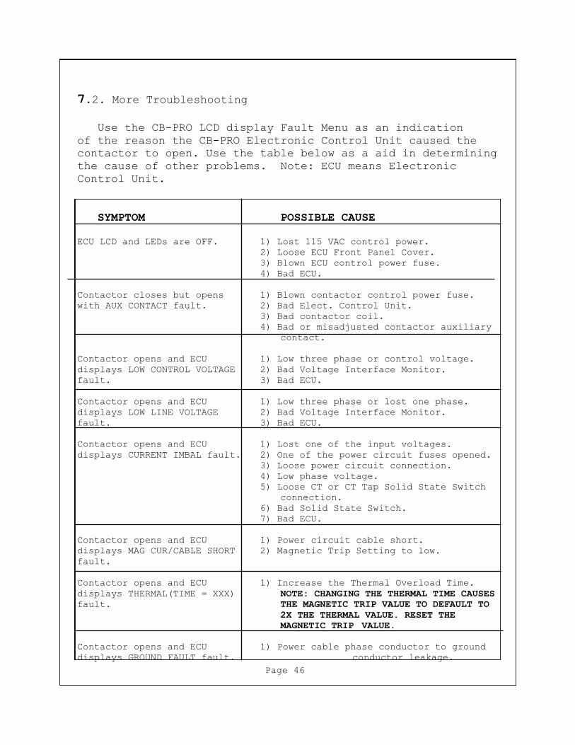
7.2. More Troubleshooting
Use the CB-PRO LCD display Fault Menu as an indication
of the reason the CB-PRO Electronic Control Unit caused the
contactor to open. Use the table below as a aid in determining
the cause of other problems. Note: ECU means Electronic
Control Unit.
SYMPTOM POSSIBLE CAUSE
ECU LCD and LEDs are OFF. 1) Lost 115 VAC control power.
2) Loose ECU Front Panel Cover.
3) Blown ECU control power fuse.
4) Bad ECU.
Contactor closes but opens 1) Blown contactor control power fuse.
with AUX CONTACT fault. 2) Bad Elect. Control Unit.
3) Bad contactor coil.
4) Bad or misadjusted contactor auxiliary
contact.
Contactor opens and ECU 1) Low three phase or control voltage.
displays LOW CONTROL VOLTAGE 2) Bad Voltage Interface Monitor.
fault. 3) Bad ECU.
Contactor opens and ECU 1) Low three phase or lost one phase.
displays LOW LINE VOLTAGE 2) Bad Voltage Interface Monitor.
fault. 3) Bad ECU.
Contactor opens and ECU 1) Lost one of the input voltages.
displays CURRENT IMBAL fault. 2) One of the power circuit fuses opened.
3) Loose power circuit connection.
4) Low phase voltage.
5) Loose CT or CT Tap Solid State Switch
connection.
6) Bad Solid State Switch.
7) Bad ECU.
Contactor opens and ECU 1) Power circuit cable short.
displays MAG CUR/CABLE SHORT 2) Magnetic Trip Setting to low.
fault.
Contactor opens and ECU 1) Increase the Thermal Overload Time.
displays THERMAL(TIME = XXX) NOTE: CHANGING THE THERMAL TIME CAUSES
fault. THE MAGNETIC TRIP VALUE TO DEFAULT TO
2X THE THERMAL VALUE. RESET THE
MAGNETIC TRIP VALUE.
Contactor opens and ECU 1) Power cable phase conductor to ground
displays GROUND FAULT fault. conductor leakage.
Page 46
8. Spare Parts
Amr Part Number Description
140-0173 Electronic Control Unit
140-0174-300 CB-PRO 300 Voltage Interface Assembly
140-0174-450 CB-PRO 450 Voltage Interface Assembly
140-0174-550 CB-PRO 550 Voltage Interface Assembly
253-0319 Back Panel PCB Assembly
253-0323 Front Panel PCB Assembly
253-0325 Communications PCB Assembly
253-0339-300 CB-PRO 300 Solid Stage Switch PCB
253-0339-450 CB-PRO 450 Solid Stage Switch PCB
253-0339-550 CB-PRO 550 Solid Stage Switch PCB
130-0079 Phase Current Transformer
130-0092 Ground Fault Current Transformer
(300 Amp Applications)
130-0094 Ground Fault Current Transformer
(450 & 550 Amp Applications)
160-0029 Bussman 600 Amp Fuse
160-0022 Bussman 700 Amp Fuse
271-0081 Front Panel Assembly
195-0196 Ribbon Cable Assembly
Page 47
6000
0.0
16100
0.0
04
5200
0.0
26000
0.0
1
5000
0.0
35900
0.0
2
4000
0.0
45750
0.8
3000
9000000
61.3
3333
0.0
65500
6
2500
6250000
88.3
20.0
85400
15
2000
4000000
138
0.1
5250
50
1500
2250000
245.3
333
0.2
5100
250
1000
1000000
552
0.3
5000
2500
900
0.4
4850
10000
4500
0.6
4650
0.2
5
2400
0.8
4550
0.9
5
1800
14475
2
600
24250
20
300
34000
200
43800
4000
63650
1.1
2400
83450
3
1800
10
3300
6
600
20
3100
60
300
30
2850
700
40
2500
4000
60
2300
2.2
2400
80
2150
5.6
1800
100
2025
10
600
200
1800
100
300
300
1700
1300
400
1550
4000
600
1450
4
2400
800
1400
12
1800
20
600
200
300
2500
0.0
45
100
0.0
45
7000
4000
6.2
2400
18
0.0
35
200
1800
30
8000
200
600
300
300
4000
0.0
35
600
8000
600
3000
16
2400
24
0.0
35
1600
1800
40
8000
1600
600
400
300
5000
3000
18
2400
26
1800
45
600
450
300
6000
CB
-PR
O 3
00
CU
RR
EN
T V
S. O
PE
N T
IME
FO
R C
LA
SS
2, 6
, 1
0, 2
0, 3
0, 4
0, A
ND
50
LO
AD
S
TH
ER
MA
L C
UR
RE
NT
RA
TIN
G A
T X
= 1
00 A
MP
ER
ES
0.0
01
0.0
1
0.11
10
100
1000
10000
100
1000
10000
CU
RR
EN
T I
N A
MP
S
TIME IN SECONDS
Fuse
Cla
ss 6
Cla
ss 1
0
Cla
ss 2
0
Cla
ss 3
0
Cla
ss 4
0
Cla
ss 4
5
Inst.
Trip
2X
6X
16X
cla
ss 2
Page 48
FIG
UR
E 3
,

6000
0.0
16100
0.0
04
5200
0.0
26000
0.0
1
5000
0.0
35900
0.0
2
4000
0.0
45750
0.8
3000
9000000
61.3
3333
0.0
65500
6
2500
6250000
88.3
20.0
85400
15
2000
4000000
138
0.1
5250
50
1500
2250000
245.3
333
0.2
5100
250
1000
1000000
552
0.3
5000
2500
900
0.4
4850
10000
4500
0.6
4650
0.2
5
2400
0.8
4550
0.9
5
1800
14475
2
600
24250
20
300
34000
200
43800
4000
63650
1.1
2400
83450
3
1800
10
3300
6
600
20
3100
60
300
30
2850
700
40
2500
4000
60
2300
2.2
2400
80
2150
5.6
1800
100
2025
10
600
200
1800
100
300
300
1700
1300
400
1550
4000
600
1450
4
2400
800
1400
12
1800
20
600
200
300
2500
0.0
45
100
0.0
45
7000
4000
6.2
2400
18
0.0
35
300
1800
30
8000
300
600
300
300
4000
0.0
35
900
8000
900
3000
16
2400
24
0.0
35
2400
1800
40
8000
2400
600
400
300
5000
3000
18
2400
26
1800
45
600
450
300
6000
CB
-PR
O 3
00
CU
RR
EN
T V
S. O
PE
N T
IME
FO
R C
LA
SS
2, 6
, 1
0, 2
0, 3
0, 4
0, A
ND
50
LO
AD
S
TH
ER
MA
L C
UR
RE
NT
RA
TIN
G A
T X
= 1
50 A
MP
ER
ES
0.0
01
0.0
1
0.11
10
100
1000
10000
100
1000
10000
CU
RR
EN
T I
N A
MP
S
TIME IN SECONDS
Fuse
Cla
ss 6
Cla
ss 1
0
Cla
ss 2
0
Cla
ss 3
0
Cla
ss 4
0
Cla
ss 4
5
Inst.
Trip
2X
6X
16X
cla
ss 2
Page 49
FIG
UR
E 4
,
6000
0.0
16100
0.0
04
5200
0.0
26000
0.0
1
5000
0.0
35900
0.0
2
4000
0.0
45750
0.8
3000
9000000
61.3
3333
0.0
65500
6
2500
6250000
88.3
20.0
85400
15
2000
4000000
138
0.1
5250
50
1500
2250000
245.3
333
0.2
5100
250
1000
1000000
552
0.3
5000
2500
900
0.4
4850
10000
4500
0.6
4650
0.2
5
2400
0.8
4550
0.9
5
1800
14475
2
600
24250
20
300
34000
200
43800
4000
63650
1.1
2400
83450
3
1800
10
3300
6
600
20
3100
60
300
30
2850
700
40
2500
4000
60
2300
2.2
2400
80
2150
5.6
1800
100
2025
10
600
200
1800
100
300
300
1700
1300
400
1550
4000
600
1450
4
2400
800
1400
12
1800
20
600
200
300
2500
0.0
45
100
0.0
45
7000
4000
6.2
2400
18
0.0
35
400
1800
30
8000
400
600
300
300
4000
0.0
35
1200
8000
1200
3000
16
2400
24
0.0
35
3200
1800
40
8000
3200
600
400
300
5000
3000
18
2400
26
1800
45
600
450
300
6000
CB
-PR
O 3
00
CU
RR
EN
T V
S. O
PE
N T
IME
FO
R C
LA
SS
2, 6
, 1
0, 2
0, 3
0, 4
0, A
ND
50
LO
AD
S
TH
ER
MA
L C
UR
RE
NT
RA
TIN
G A
T X
= 2
00 A
MP
ER
ES
0.0
01
0.0
1
0.11
10
100
1000
10000
100
1000
10000
CU
RR
EN
T I
N A
MP
S
TIME IN SECONDS
Fuse
Cla
ss 6
Cla
ss 1
0
Cla
ss 2
0
Cla
ss 3
0
Cla
ss 4
0
Cla
ss 4
5
Inst.
Trip
2X
6X
16X
cla
ss 2
Page 50
FIG
UR
E 5
,
6000
0.0
16100
0.0
04
5200
0.0
26000
0.0
1
5000
0.0
35900
0.0
2
4000
0.0
45750
0.8
3000
9000000
61.3
3333
0.0
65500
6
2500
6250000
88.3
20.0
85400
15
2000
4000000
138
0.1
5250
50
1500
2250000
245.3
333
0.2
5100
250
1000
1000000
552
0.3
5000
2500
900
0.4
4850
10000
4500
0.6
4650
0.2
5
2400
0.8
4550
0.9
5
1800
14475
2
600
24250
20
300
34000
200
43800
4000
63650
1.1
2400
83450
3
1800
10
3300
6
600
20
3100
60
300
30
2850
700
40
2500
4000
60
2300
2.2
2400
80
2150
5.6
1800
100
2025
10
600
200
1800
100
300
300
1700
1300
400
1550
4000
600
1450
4
2400
800
1400
12
1800
20
600
200
300
2500
0.0
45
100
0.0
45
7000
4000
6.2
2400
18
0.0
35
500
1800
30
8000
500
600
300
300
4000
0.0
35
1500
8000
1500
3000
16
2400
24
0.0
35
4000
1800
40
8000
4000
600
400
300
5000
3000
18
2400
26
1800
45
600
450
300
6000
CB
-PR
O 3
00
CU
RR
EN
T V
S. O
PE
N T
IME
FO
R C
LA
SS
2, 6
, 1
0, 2
0, 3
0, 4
0, A
ND
50
LO
AD
S
TH
ER
MA
L C
UR
RE
NT
RA
TIN
G A
T X
= 2
50 A
MP
ER
ES
0.0
01
0.0
1
0.11
10
100
1000
10000
100
1000
10000
CU
RR
EN
T I
N A
MP
S
TIME IN SECONDS
Fuse
Cla
ss 6
Cla
ss 1
0
Cla
ss 2
0
Cla
ss 3
0
Cla
ss 4
0
Cla
ss 4
5
Inst.
Trip
2X
6X
16X
cla
ss 2
Page 51
FIG
UR
E 6
,
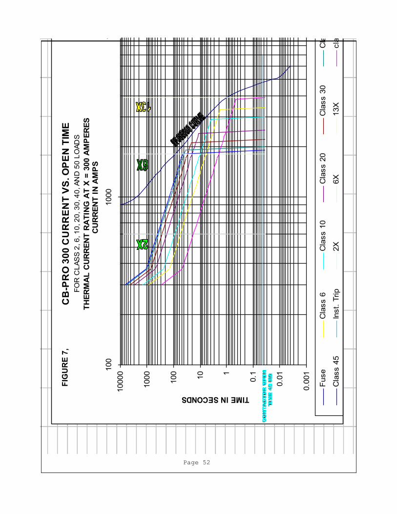
6000
0.0
16100
0.0
04
6000
0.0
025
5200
0.0
26000
0.0
15000
0.0
04
5000
0.0
35900
0.0
24000
0.0
7
4000
0.0
45750
0.8
3500
0.5
3000
9000000
61.3
3333
0.0
65500
63000
2.5
2500
6250000
88.3
20.0
85400
15
2500
7
2000
4000000
138
0.1
5250
50
2000
20
1500
2250000
245.3
333
0.2
5100
250
1500
100
1000
1000000
552
0.3
5000
2500
1000
800
900
0.4
4850
10000
750
10000
4500
0.6
4650
0.2
5
2400
0.8
4550
0.9
5
1800
14475
2
600
24250
20
300
34000
200
43800
4000
63650
1.1
2400
83450
3
1800
10
3300
6
600
20
3100
60
300
30
2850
700
40
2500
4000
60
2300
2.2
2400
80
2150
5.6
1800
100
2025
10
600
200
1800
100
300
300
1700
1300
400
1550
4000
600
1450
4
2400
800
1400
12
1800
20
600
200
300
0.0
45
100
2500
0.0
45
7000
4000
6.2
2400
0.0
35
600
18
1800
8000
600
30
600
300
300
0.0
35
1800
4000
8000
1800
3000
16
2400
0.0
35
3900
24
1800
8000
3900
40
600
400
300
5000
3000
18
2400
26
1800
45
600
450
300
6000
CB
-PR
O 3
00
CU
RR
EN
T V
S. O
PE
N T
IME
FO
R C
LA
SS
2, 6
, 1
0, 2
0, 3
0, 4
0, A
ND
50
LO
AD
S
TH
ER
MA
L C
UR
RE
NT
RA
TIN
G A
T X
= 3
00 A
MP
ER
ES
0.0
01
0.0
1
0.11
10
100
1000
10000
100
1000
10000
CU
RR
EN
T I
N A
MP
S
TIME IN SECONDS
Fuse
Cla
ss 6
Cla
ss 1
0C
lass 2
0C
lass 3
0C
lass 4
0
Cla
ss 4
5In
st.
Trip
2X
6X
13X
cla
ss 2
Page 52
FIG
UR
E 7
,

6000
0.0
16100
0.0
04
5200
0.0
26000
0.0
1
5000
0.0
35900
0.0
2
4000
0.0
45750
0.8
3000
9000000
61.3
3333
0.0
65500
6
2500
6250000
88.3
20.0
85400
15
2000
4000000
138
0.1
5250
50
1500
2250000
245.3
333
0.2
5100
250
1000
1000000
552
0.3
5000
2500
900
0.4
4850
10000
4500
0.6
4650
0.2
5
2400
0.8
4550
0.9
5
1800
14475
2
600
24250
20
300
34000
200
43800
4000
63650
1.1
2400
83450
3
1800
10
3300
6
600
20
3100
60
300
30
2850
700
40
2500
4000
60
2300
2.2
2400
80
2150
5.6
1800
100
2025
10
600
200
1800
100
300
300
1700
1300
400
1550
4000
600
1450
4
2400
800
1400
12
1800
20
600
200
300
2500
0.0
54
100
0.0
54
7000
4000
6.2
2400
18
0.0
35
200
1800
30
8000
200
600
300
300
4000
0.0
35
600
8000
600
3000
16
2400
24
0.0
35
1600
1800
40
8000
1600
600
400
300
5000
3000
18
2400
26
1800
45
600
450
300
6000
CB
-PR
O 4
50
CU
RR
EN
T V
S. O
PE
N T
IME
FO
R C
LA
SS
2, 6
, 1
0, 2
0, 3
0, 4
0, A
ND
50
LO
AD
S
TH
ER
MA
L C
UR
RE
NT
RA
TIN
G A
T X
= 1
00 A
MP
ER
ES
0.0
01
0.0
1
0.11
10
100
1000
10000
100
1000
10000
CU
RR
EN
T I
N A
MP
S
TIME IN SECONDS
Fuse
Cla
ss 6
Cla
ss 1
0
Cla
ss 2
0
Cla
ss 3
0
Cla
ss 4
0
Cla
ss 4
5
Inst.
Trip
2X
6X
16X
cla
ss 2
Page 53
FIG
UR
E 8
,
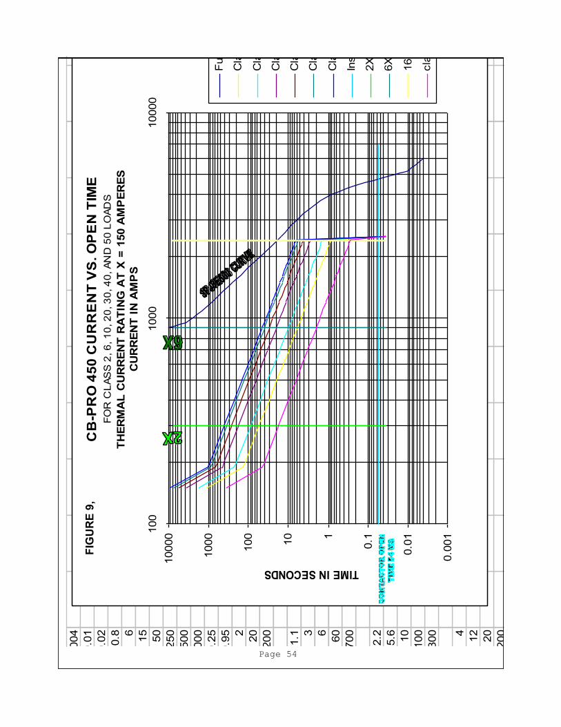
6000
0.0
16100
0.0
04
5200
0.0
26000
0.0
1
5000
0.0
35900
0.0
2
4000
0.0
45750
0.8
3000
9000000
61.3
3333
0.0
65500
6
2500
6250000
88.3
20.0
85400
15
2000
4000000
138
0.1
5250
50
1500
2250000
245.3
333
0.2
5100
250
1000
1000000
552
0.3
5000
2500
900
0.4
4850
10000
4500
0.6
4650
0.2
5
2400
0.8
4550
0.9
5
1800
14475
2
600
24250
20
300
34000
200
43800
4000
63650
1.1
2400
83450
3
1800
10
3300
6
600
20
3100
60
300
30
2850
700
40
2500
4000
60
2300
2.2
2400
80
2150
5.6
1800
100
2025
10
600
200
1800
100
300
300
1700
1300
400
1550
4000
600
1450
4
2400
800
1400
12
1800
20
600
200
300
2500
0.0
54
100
0.0
54
7000
4000
6.2
2400
18
0.0
35
300
1800
30
8000
300
600
300
300
4000
0.0
35
900
8000
900
3000
16
2400
24
0.0
35
2400
1800
40
8000
2400
600
400
300
5000
3000
18
2400
26
1800
45
600
450
300
6000
CB
-PR
O 4
50
CU
RR
EN
T V
S. O
PE
N T
IME
FO
R C
LA
SS
2, 6
, 1
0, 2
0, 3
0, 4
0, A
ND
50
LO
AD
S
TH
ER
MA
L C
UR
RE
NT
RA
TIN
G A
T X
= 1
50 A
MP
ER
ES
0.0
01
0.0
1
0.11
10
100
1000
10000
100
1000
10000
CU
RR
EN
T I
N A
MP
S
TIME IN SECONDS
Fuse
Cla
ss 6
Cla
ss 1
0
Cla
ss 2
0
Cla
ss 3
0
Cla
ss 4
0
Cla
ss 4
5
Inst.
Trip
2X
6X
16X
cla
ss 2
Page 54
FIG
UR
E 9
,

6000
0.0
16100
0.0
04
5200
0.0
26000
0.0
1
5000
0.0
35900
0.0
2
4000
0.0
45750
0.8
3000
9000000
61.3
3333
0.0
65500
6
2500
6250000
88.3
20.0
85400
15
2000
4000000
138
0.1
5250
50
1500
2250000
245.3
333
0.2
5100
250
1000
1000000
552
0.3
5000
2500
900
0.4
4850
10000
4500
0.6
4650
0.2
5
2400
0.8
4550
0.9
5
1800
14475
2
600
24250
20
300
34000
200
43800
4000
63650
1.1
2400
83450
3
1800
10
3300
6
600
20
3100
60
300
30
2850
700
40
2500
4000
60
2300
2.2
2400
80
2150
5.6
1800
100
2025
10
600
200
1800
100
300
300
1700
1300
400
1550
4000
600
1450
4
2400
800
1400
12
1800
20
600
200
300
2500
0.0
54
100
0.0
54
7000
4000
6.2
2400
18
0.0
35
400
1800
30
8000
400
600
300
300
4000
0.0
35
1200
8000
1200
3000
16
2400
24
0.0
35
3200
1800
40
8000
3200
600
400
300
5000
3000
18
2400
26
1800
45
600
450
300
6000
CB
-PR
O 4
50
CU
RR
EN
T V
S. O
PE
N T
IME
FO
R C
LA
SS
2, 6
, 1
0, 2
0, 3
0, 4
0, A
ND
50
LO
AD
S
TH
ER
MA
L C
UR
RE
NT
RA
TIN
G A
T X
= 2
00 A
MP
ER
ES
0.0
01
0.0
1
0.11
10
100
1000
10000
100
1000
10000
CU
RR
EN
T I
N A
MP
S
TIME IN SECONDS
Fuse
Cla
ss 6
Cla
ss 1
0
Cla
ss 2
0
Cla
ss 3
0
Cla
ss 4
0
Cla
ss 4
5
Inst.
Trip
2X
6X
16X
cla
ss 2
Page 55
FIG
UR
E 1
0,
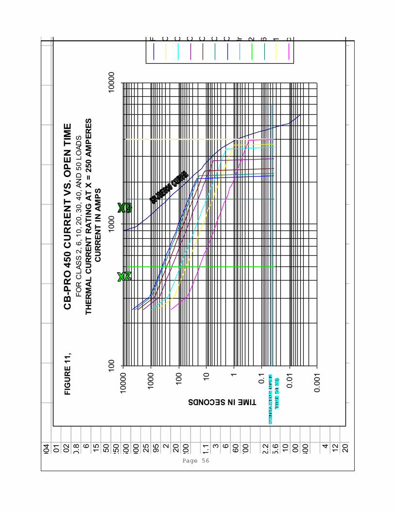
6000
0.0
16100
0.0
04
5200
0.0
26000
0.0
1
5000
0.0
35900
0.0
2
4000
0.0
45750
0.8
3000
9000000
61.3
3333
0.0
65500
6
2500
6250000
88.3
20.0
85400
15
2000
4000000
138
0.1
5250
50
1500
2250000
245.3
333
0.2
5100
250
1000
1000000
552
0.3
5000
2500
900
0.4
4850
10000
4500
0.6
4650
0.2
5
2400
0.8
4550
0.9
5
1800
14475
2
600
24250
20
300
34000
200
43800
4000
63650
1.1
2400
83450
3
1800
10
3300
6
600
20
3100
60
300
30
2850
700
40
2500
4000
60
2300
2.2
2400
80
2150
5.6
1800
100
2025
10
600
200
1800
100
300
300
1700
1300
400
1550
4000
600
1450
4
2400
800
1400
12
1800
20
600
200
300
2500
0.0
45
100
0.0
45
7000
4000
6.2
2400
18
0.0
35
500
1800
30
8000
500
600
300
300
4000
0.0
35
1500
8000
1500
3000
16
2400
24
0.0
35
4000
1800
40
8000
4000
600
400
300
5000
3000
18
2400
26
1800
45
600
450
300
6000
CB
-PR
O 4
50
CU
RR
EN
T V
S. O
PE
N T
IME
FO
R C
LA
SS
2, 6
, 1
0, 2
0, 3
0, 4
0, A
ND
50
LO
AD
S
TH
ER
MA
L C
UR
RE
NT
RA
TIN
G A
T X
= 2
50 A
MP
ER
ES
0.0
01
0.0
1
0.11
10
100
1000
10000
100
1000
10000
CU
RR
EN
T I
N A
MP
S
TIME IN SECONDS
Fuse
Cla
ss 6
Cla
ss 1
0
Cla
ss 2
0
Cla
ss 3
0
Cla
ss 4
0
Cla
ss 4
5
Inst.
Trip
2X
6X
16X
cla
ss 2
Page 56
FIG
UR
E 1
1,

6000
0.0
16100
0.0
04
6000
0.0
025
5200
0.0
26000
0.0
15000
0.0
04
5000
0.0
35900
0.0
24000
0.0
7
4000
0.0
45750
0.8
3500
0.5
3000
9000000
61.3
3333
0.0
65500
63000
2.5
2500
6250000
88.3
20.0
85400
15
2500
7
2000
4000000
138
0.1
5250
50
2000
20
1500
2250000
245.3
333
0.2
5100
250
1500
100
1000
1000000
552
0.3
5000
2500
1000
800
900
0.4
4850
10000
750
10000
4500
0.6
4650
0.2
5
2400
0.8
4550
0.9
5
1800
14475
2
600
24250
20
300
34000
200
43800
4000
63650
1.1
2400
83450
3
1800
10
3300
6
600
20
3100
60
300
30
2850
700
40
2500
4000
60
2300
2.2
2400
80
2150
5.6
1800
100
2025
10
600
200
1800
100
300
300
1700
1300
400
1550
4000
600
1450
4
2400
800
1400
12
1800
20
600
200
300
0.0
54
100
2500
0.0
54
7000
4000
6.2
2400
0.0
35
600
18
1800
8000
600
30
600
300
300
0.0
35
1800
4000
8000
1800
3000
16
2400
0.0
35
3900
24
1800
8000
3900
40
600
400
300
5000
3000
18
2400
26
1800
45
600
450
300
6000
CB
-PR
O 4
50
CU
RR
EN
T V
S. O
PE
N T
IME
FO
R C
LA
SS
2, 6
, 1
0, 2
0, 3
0, 4
0, A
ND
50
LO
AD
S
TH
ER
MA
L C
UR
RE
NT
RA
TIN
G A
T X
= 3
00 A
MP
ER
ES
0.0
01
0.0
1
0.11
10
100
1000
10000
100
1000
10000
CU
RR
EN
T I
N A
MP
S
TIME IN SECONDS
Fuse
Cla
ss 6
Cla
ss 1
0C
lass 2
0C
lass 3
0C
lass 4
0
Cla
ss 4
5In
st.
Trip
2X
6X
13X
cla
ss 2
Page 57
FIG
UR
E 1
2,

6000
0.0
16100
0.0
04
6000
0.0
025
5200
0.0
26000
0.0
15000
0.0
04
5000
0.0
35900
0.0
24000
0.0
7
4000
0.0
45750
0.8
3500
0.5
3000
9000000
61.3
3333
0.0
65500
63000
2.5
2500
6250000
88.3
20.0
85400
15
2500
7
2000
4000000
138
0.1
5250
50
2000
20
1500
2250000
245.3
333
0.2
5100
250
1500
100
1000
1000000
552
0.3
5000
2500
1000
800
900
0.4
4850
10000
750
10000
4500
0.6
4650
0.2
5
2400
0.8
4550
0.9
5
1800
14475
2
600
24250
20
300
34000
200
43800
4000
63650
1.1
2400
83450
3
1800
10
3300
6
600
20
3100
60
300
30
2850
700
40
2500
4000
60
2300
2.2
2400
80
2150
5.6
1800
100
2025
10
600
200
1800
100
300
300
1700
1300
400
1550
4000
600
1450
4
2400
800
1400
12
1800
20
600
200
300
0.0
54
100
2500
0.0
54
7000
4000
6.2
2400
0.0
35
700
18
1800
8000
700
30
600
300
300
0.0
35
2100
4000
8000
2100
3000
16
2400
0.0
35
3600
24
1800
8000
3600
40
600
400
300
5000
3000
18
2400
26
1800
45
600
450
300
6000
CB
-PR
O 4
50
CU
RR
EN
T V
S. O
PE
N T
IME
FO
R C
LA
SS
2, 6
, 1
0, 2
0, 3
0, 4
0, A
ND
50
LO
AD
S
TH
ER
MA
L C
UR
RE
NT
RA
TIN
G A
T X
= 3
50 A
MP
ER
ES
0.0
01
0.0
1
0.11
10
100
1000
10000
100
1000
10000
CU
RR
EN
T I
N A
MP
S
TIME IN SECONDS
Fuse
Cla
ss 6
Cla
ss 1
0C
lass 2
0C
lass 3
0C
lass 4
0
Cla
ss 4
5In
st.
Trip
2X
6X
10X
cla
ss 2
Page 58
FIG
UR
E 1
3,
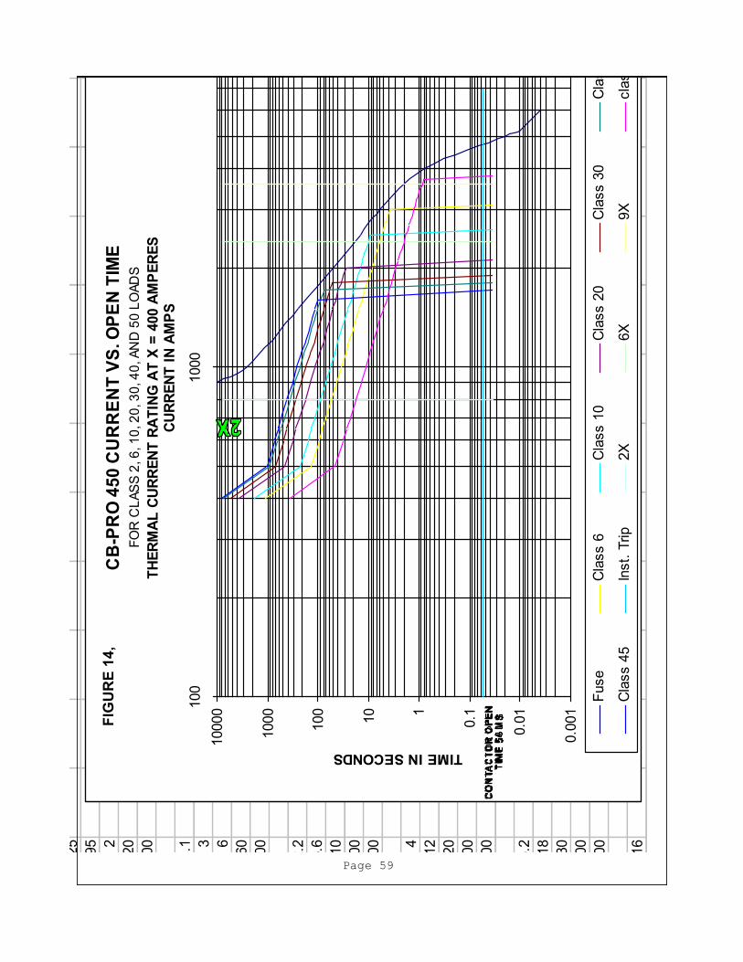
6000
0.0
16100
0.0
04
6000
0.0
025
5200
0.0
26000
0.0
15000
0.0
04
5000
0.0
35900
0.0
24000
0.0
7
4000
0.0
45750
0.8
3500
0.5
3000
9000000
61.3
3333
0.0
65500
63000
2.5
2500
6250000
88.3
20.0
85400
15
2500
7
2000
4000000
138
0.1
5250
50
2000
20
1500
2250000
245.3
333
0.2
5100
250
1500
100
1000
1000000
552
0.3
5000
2500
1000
800
900
0.4
4850
10000
750
10000
4500
0.6
4650
0.2
5
2400
0.8
4550
0.9
5
1800
14475
2
600
24250
20
300
34000
200
43800
4000
63650
1.1
2400
83450
3
1800
10
3300
6
600
20
3100
60
300
30
2850
700
40
2500
4000
60
2300
2.2
2400
80
2150
5.6
1800
100
2025
10
600
200
1800
100
300
300
1700
1300
400
1550
4000
600
1450
4
2400
800
1400
12
1800
20
600
200
300
0.0
54
100
2500
0.0
54
7000
4000
6.2
2400
0.0
35
800
18
1800
8000
800
30
600
300
300
0.0
35
2400
4000
8000
2400
3000
16
2400
0.0
35
3600
24
1800
8000
3600
40
600
400
300
5000
3000
18
2400
26
1800
45
600
450
300
6000
CB
-PR
O 4
50
CU
RR
EN
T V
S. O
PE
N T
IME
FO
R C
LA
SS
2, 6
, 1
0, 2
0, 3
0, 4
0, A
ND
50
LO
AD
S
TH
ER
MA
L C
UR
RE
NT
RA
TIN
G A
T X
= 4
00 A
MP
ER
ES
0.0
01
0.0
1
0.11
10
100
1000
10000
100
1000
10000
CU
RR
EN
T I
N A
MP
S
TIME IN SECONDS
Fuse
Cla
ss 6
Cla
ss 1
0C
lass 2
0C
lass 3
0C
lass 4
0
Cla
ss 4
5In
st.
Trip
2X
6X
9X
cla
ss 2
Page 59
FIG
UR
E 1
4,

6000
0.0
16100
0.0
04
6000
0.0
025
5200
0.0
26000
0.0
15000
0.0
04
5000
0.0
35900
0.0
24000
0.0
7
4000
0.0
45750
0.8
3500
0.5
3000
9000000
61.3
3333
0.0
65500
63000
2.5
2500
6250000
88.3
20.0
85400
15
2500
7
2000
4000000
138
0.1
5250
50
2000
20
1500
2250000
245.3
333
0.2
5100
250
1500
100
1000
1000000
552
0.3
5000
2500
1000
800
900
0.4
4850
10000
750
10000
4500
0.6
4650
0.2
5
2400
0.8
4550
0.9
5
1800
14475
2
600
24250
20
300
34000
200
43800
4000
63650
1.1
2400
83450
3
1800
10
3300
6
600
20
3100
60
300
30
2850
700
40
2500
4000
60
2300
2.2
2400
80
2150
5.6
1800
100
2025
10
600
200
1800
100
300
300
1700
1300
400
1550
4000
600
1450
4
2400
800
1400
12
1800
20
600
200
300
0.0
54
100
2500
0.0
54
7000
4000
6.2
2400
0.0
35
900
18
1800
8000
900
30
600
300
300
0.0
35
2700
4000
8000
2700
3000
16
2400
0.0
35
3600
24
1800
8000
3600
40
600
400
300
5000
3000
18
2400
26
1800
45
600
450
300
6000
CB
-PR
O 4
50
CU
RR
EN
T V
S. O
PE
N T
IME
FO
R C
LA
SS
2, 6
, 1
0, 2
0, 3
0, 4
0, A
ND
50
LO
AD
S
TH
ER
MA
L C
UR
RE
NT
RA
TIN
G A
T X
= 4
50 A
MP
ER
ES
0.0
01
0.0
1
0.11
10
100
1000
10000
100
1000
10000
CU
RR
EN
T I
N A
MP
S
TIME IN SECONDS
Fuse
Cla
ss 6
Cla
ss 1
0C
lass 2
0C
lass 3
0C
lass 4
0
Cla
ss 4
5In
st.
Trip
2X
6X
8X
cla
ss 2
Page 60
FIG
UR
E 1
5,

6000
0.0
16100
0.0
1
5400
0.0
26000
0.0
45
5000
0.0
35900
0.2
5
4000
0.0
45750
2.5
3000
9000000
61.3
3333
0.0
65500
15
2500
6250000
88.3
20.0
85400
40
2000
4000000
138
0.1
5250
130
1500
2250000
245.3
333
0.2
5100
500
1000
1000000
552
0.3
5000
10000
900
0.4
4850
25000
4500
0.6
4650
0.2
5
2400
0.8
4550
0.9
5
1800
14475
2
600
24250
20
300
34000
200
43800
4000
63650
1.1
2400
83450
3
1800
10
3300
6
600
20
3100
60
300
30
2850
700
40
2500
4000
60
2300
2.2
2400
80
2150
5.6
1800
100
2025
10
600
200
1800
100
300
300
1700
1300
400
1550
4000
600
1450
4
2400
800
1400
12
1800
20
600
200
300
0.0
84
100
2500
0.0
84
7000
4000
6.2
2400
0.0
35
200
18
1800
8000
200
30
600
300
300
0.0
35
600
4000
8000
600
3000
16
2400
0.0
35
1600
24
1800
8000
1600
40
600
400
300
5000
3000
18
2400
26
1800
45
600
450
300
6000
CB
-PR
O 5
50
CU
RR
EN
T V
S. O
PE
N T
IME
FO
R C
LA
SS
2, 6
, 1
0, 2
0, 3
0, 4
0, A
ND
50
LO
AD
S
TH
ER
MA
L C
UR
RE
NT
RA
TIN
G A
T X
= 1
00 A
MP
ER
ES
0.0
1
0.11
10
100
1000
10000
100000
100
1000
10000
CU
RR
EN
T I
N A
MP
S
TIME IN SECONDS
Fuse
Cla
ss 6
Cla
ss 1
0
Cla
ss 2
0
Cla
ss 3
0
Cla
ss 4
0
Cla
ss 4
5
Inst.
Trip
2X
6X
16X
cla
ss 2
Page 61
FIG
UR
E 1
6,

6000
0.0
16100
0.0
1
5400
0.0
26000
0.0
45
5000
0.0
35900
0.2
5
4000
0.0
45750
2.5
3000
9000000
61.3
3333
0.0
65500
15
2500
6250000
88.3
20.0
85400
40
2000
4000000
138
0.1
5250
130
1500
2250000
245.3
333
0.2
5100
500
1000
1000000
552
0.3
5000
10000
900
0.4
4850
25000
4500
0.6
4650
0.2
5
2400
0.8
4550
0.9
5
1800
14475
2
600
24250
20
300
34000
200
43800
4000
63650
1.1
2400
83450
3
1800
10
3300
6
600
20
3100
60
300
30
2850
700
40
2500
4000
60
2300
2.2
2400
80
2150
5.6
1800
100
2025
10
600
200
1800
100
300
300
1700
1300
400
1550
4000
600
1450
4
2400
800
1400
12
1800
20
600
200
300
0.0
84
100
2500
0.0
84
7000
4000
6.2
2400
0.0
35
400
18
1800
8000
400
30
600
300
300
0.0
35
1200
4000
8000
1200
3000
16
2400
0.0
35
3200
24
1800
8000
3200
40
600
400
300
5000
3000
18
2400
26
1800
45
600
450
300
6000
CB
-PR
O 5
50
CU
RR
EN
T V
S. O
PE
N T
IME
FO
R C
LA
SS
2, 6
, 1
0, 2
0, 3
0, 4
0, A
ND
50
LO
AD
S
TH
ER
MA
L C
UR
RE
NT
RA
TIN
G A
T X
= 2
00 A
MP
ER
ES
0.0
1
0.11
10
100
1000
10000
100000
100
1000
10000
CU
RR
EN
T I
N A
MP
S
TIME IN SECONDS
Fuse
Cla
ss 6
Cla
ss 1
0
Cla
ss 2
0
Cla
ss 3
0
Cla
ss 4
0
Cla
ss 4
5
Inst.
Trip
2X
6X
16X
cla
ss 2
Page 62
FIG
UR
E 1
7,

6000
0.0
16100
0.0
16000
0.0
025
5400
0.0
26000
0.0
45
5000
0.0
04
5000
0.0
35900
0.2
54000
0.0
7
4000
0.0
45750
2.5
3500
0.5
3000
9000000
61.3
3333
0.0
65500
15
3000
2.5
2500
6250000
88.3
20.0
85400
40
2500
7
2000
4000000
138
0.1
5250
130
2000
20
1500
2250000
245.3
333
0.2
5100
500
1500
100
1000
1000000
552
0.3
5000
10000
1000
800
900
0.4
4850
25000
750
10000
4500
0.6
4650
0.2
5
2400
0.8
4550
0.9
5
1800
14475
2
600
24250
20
300
34000
200
43800
4000
63650
1.1
2400
83450
3
1800
10
3300
6
600
20
3100
60
300
30
2850
700
40
2500
4000
60
2300
2.2
2400
80
2150
5.6
1800
100
2025
10
600
200
1800
100
300
300
1700
1300
400
1550
4000
600
1450
4
2400
800
1400
12
1800
20
600
200
300
0.0
84
100
2500
0.0
84
7000
4000
6.2
2400
0.0
35
500
18
1800
8000
500
30
600
300
300
0.0
35
1500
4000
8000
1500
3000
16
2400
0.0
35
4000
24
1800
8000
4000
40
600
400
300
5000
3000
18
2400
26
1800
45
600
450
300
6000
CB
-PR
O 5
50
CU
RR
EN
T V
S. O
PE
N T
IME
FO
R C
LA
SS
2, 6
, 1
0, 2
0, 3
0, 4
0, A
ND
50
LO
AD
S
TH
ER
MA
L C
UR
RE
NT
RA
TIN
G A
T X
= 2
50 A
MP
ER
ES
0.0
1
0.11
10
100
1000
10000
100000
100
1000
10000
CU
RR
EN
T I
N A
MP
S
TIME IN SECONDS
Fuse
Cla
ss 6
Cla
ss 1
0C
lass 2
0C
lass 3
0C
lass 4
0
Cla
ss 4
5In
st.
Trip
2X
6X
16X
cla
ss 2
Page 63
FIG
UR
E 1
8,

6000
0.0
16100
0.0
16000
0.0
025
5400
0.0
26000
0.0
45
5000
0.0
04
5000
0.0
35900
0.2
54000
0.0
7
4000
0.0
45750
2.5
3500
0.5
3000
9000000
61.3
3333
0.0
65500
15
3000
2.5
2500
6250000
88.3
20.0
85400
40
2500
7
2000
4000000
138
0.1
5250
130
2000
20
1500
2250000
245.3
333
0.2
5100
500
1500
100
1000
1000000
552
0.3
5000
10000
1000
800
900
0.4
4850
25000
750
10000
4500
0.6
4650
0.2
5
2400
0.8
4550
0.9
5
1800
14475
2
600
24250
20
300
34000
200
43800
4000
63650
1.1
2400
83450
3
1800
10
3300
6
600
20
3100
60
300
30
2850
700
40
2500
4000
60
2300
2.2
2400
80
2150
5.6
1800
100
2025
10
600
200
1800
100
300
300
1700
1300
400
1550
4000
600
1450
4
2400
800
1400
12
1800
20
600
200
300
0.0
84
100
2500
0.0
84
7000
4000
6.2
2400
0.0
35
600
18
1800
8000
600
30
600
300
300
0.0
35
1800
4000
8000
1800
3000
16
2400
0.0
35
4500
24
1800
8000
4500
40
600
400
300
5000
3000
18
2400
26
1800
45
600
450
300
6000
CB
-PR
O 5
50
CU
RR
EN
T V
S. O
PE
N T
IME
FO
R C
LA
SS
2, 6
, 1
0, 2
0, 3
0, 4
0, A
ND
50
LO
AD
S
TH
ER
MA
L C
UR
RE
NT
RA
TIN
G A
T X
= 3
00 A
MP
ER
ES
0.0
1
0.11
10
100
1000
10000
100000
100
1000
10000
CU
RR
EN
T I
N A
MP
S
TIME IN SECONDS
Fuse
Cla
ss 6
Cla
ss 1
0C
lass 2
0C
lass 3
0C
lass 4
0
Cla
ss 4
5In
st.
Trip
2X
6X
15X
cla
ss 2
Page 64
FIG
UR
E 1
9,

6000
0.0
16100
0.0
16000
0.0
025
5400
0.0
26000
0.0
45
5000
0.0
04
5000
0.0
35900
0.2
54000
0.0
7
4000
0.0
45750
2.5
3500
0.5
3000
9000000
61.3
3333
0.0
65500
15
3000
2.5
2500
6250000
88.3
20.0
85400
40
2500
7
2000
4000000
138
0.1
5250
130
2000
20
1500
2250000
245.3
333
0.2
5100
500
1500
100
1000
1000000
552
0.3
5000
10000
1000
800
900
0.4
4850
25000
750
10000
4500
0.6
4650
0.2
5
2400
0.8
4550
0.9
5
1800
14475
2
600
24250
20
300
34000
200
43800
4000
63650
1.1
2400
83450
3
1800
10
3300
6
600
20
3100
60
300
30
2850
700
40
2500
4000
60
2300
2.2
2400
80
2150
5.6
1800
100
2025
10
600
200
1800
100
300
300
1700
1300
400
1550
4000
600
1450
4
2400
800
1400
12
1800
20
600
200
300
0.0
84
100
2500
0.0
84
7000
4000
6.2
2400
0.0
35
700
18
1800
8000
700
30
600
300
300
0.0
35
2100
4000
8000
2100
3000
16
2400
0.0
35
4500
24
1800
8000
4500
40
600
400
300
5000
3000
18
2400
26
1800
45
600
450
300
6000
CB
-PR
O 5
50
CU
RR
EN
T V
S. O
PE
N T
IME
FO
R C
LA
SS
2, 6
, 1
0, 2
0, 3
0, 4
0, A
ND
50
LO
AD
S
TH
ER
MA
L C
UR
RE
NT
RA
TIN
G A
T X
= 3
50 A
MP
ER
ES
0.0
1
0.11
10
100
1000
10000
100000
100
1000
10000
CU
RR
EN
T I
N A
MP
S
TIME IN SECONDS
Fuse
Cla
ss 6
Cla
ss 1
0C
lass 2
0C
lass 3
0C
lass 4
0
Cla
ss 4
5In
st.
Trip
2X
6X
13X
cla
ss 2
Page 65
FIG
UR
E 2
0,
6000
0.0
16100
0.0
16000
0.0
025
5400
0.0
26000
0.0
45
5000
0.0
04
5000
0.0
35900
0.2
54000
0.0
7
4000
0.0
45750
2.5
3500
0.5
3000
9000000
61.3
3333
0.0
65500
15
3000
2.5
2500
6250000
88.3
20.0
85400
40
2500
7
2000
4000000
138
0.1
5250
130
2000
20
1500
2250000
245.3
333
0.2
5100
500
1500
100
1000
1000000
552
0.3
5000
10000
1000
800
900
0.4
4850
25000
750
10000
4500
0.6
4650
0.2
5
2400
0.8
4550
0.9
5
1800
14475
2
600
24250
20
300
34000
200
43800
4000
63650
1.1
2400
83450
3
1800
10
3300
6
600
20
3100
60
300
30
2850
700
40
2500
4000
60
2300
2.2
2400
80
2150
5.6
1800
100
2025
10
600
200
1800
100
300
300
1700
1300
400
1550
4000
600
1450
4
2400
800
1400
12
1800
20
600
200
300
0.0
84
100
2500
0.0
84
7000
4000
6.2
2400
0.0
35
800
18
1800
8000
800
30
600
300
300
0.0
35
2400
4000
8000
2400
3000
16
2400
0.0
35
4400
24
1800
8000
4400
40
600
400
300
5000
3000
18
2400
26
1800
45
600
450
300
6000
CB
-PR
O 5
50
CU
RR
EN
T V
S. O
PE
N T
IME
FO
R C
LA
SS
2, 6
, 1
0, 2
0, 3
0, 4
0, A
ND
50
LO
AD
S
TH
ER
MA
L C
UR
RE
NT
RA
TIN
G A
T X
= 4
00 A
MP
ER
ES
0.0
1
0.11
10
100
1000
10000
100000
100
1000
10000
CU
RR
EN
T I
N A
MP
S
TIME IN SECONDS
Fuse
Cla
ss 6
Cla
ss 1
0C
lass 2
0C
lass 3
0C
lass 4
0
Cla
ss 4
5In
st.
Trip
2X
6X
11X
cla
ss 2
Page 66
FIG
UR
E 2
1,

6000
0.0
16100
0.0
16000
0.0
025
5400
0.0
26000
0.0
45
5000
0.0
04
5000
0.0
35900
0.2
54000
0.0
7
4000
0.0
45750
2.5
3500
0.5
3000
9000000
61.3
3333
0.0
65500
15
3000
2.5
2500
6250000
88.3
20.0
85400
40
2500
7
2000
4000000
138
0.1
5250
130
2000
20
1500
2250000
245.3
333
0.2
5100
500
1500
100
1000
1000000
552
0.3
5000
10000
1000
800
900
0.4
4850
25000
750
10000
4500
0.6
4650
0.2
5
2400
0.8
4550
0.9
5
1800
14475
2
600
24250
20
300
34000
200
43800
4000
63650
1.1
2400
83450
3
1800
10
3300
6
600
20
3100
60
300
30
2850
700
40
2500
4000
60
2300
2.2
2400
80
2150
5.6
1800
100
2025
10
600
200
1800
100
300
300
1700
1300
400
1550
4000
600
1450
4
2400
800
1400
12
1800
20
600
200
300
0.0
84
100
2500
0.0
84
7000
4000
6.2
2400
0.0
35
900
18
1800
8000
900
30
600
300
300
0.0
35
2700
4000
8000
2700
3000
16
2400
0.0
35
4500
24
1800
8000
4500
40
600
400
300
5000
3000
18
2400
26
1800
45
600
450
300
6000
CB
-PR
O 5
50
CU
RR
EN
T V
S. O
PE
N T
IME
FO
R C
LA
SS
2, 6
, 1
0, 2
0, 3
0, 4
0, A
ND
50
LO
AD
S
TH
ER
MA
L C
UR
RE
NT
RA
TIN
G A
T X
= 4
50 A
MP
ER
ES
0.0
1
0.11
10
100
1000
10000
100000
100
1000
10000
CU
RR
EN
T I
N A
MP
S
TIME IN SECONDS
Fuse
Cla
ss 6
Cla
ss 1
0C
lass 2
0C
lass 3
0C
lass 4
0
Cla
ss 4
5In
st.
Trip
2X
6X
10X
cla
ss 2
Page 67
FIG
UR
E 2
2,

6000
0.0
16100
0.0
16000
0.0
025
5400
0.0
26000
0.0
45
5000
0.0
04
5000
0.0
35900
0.2
54000
0.0
7
4000
0.0
45750
2.5
3500
0.5
3000
9000000
61.3
3333
0.0
65500
15
3000
2.5
2500
6250000
88.3
20.0
85400
40
2500
7
2000
4000000
138
0.1
5250
130
2000
20
1500
2250000
245.3
333
0.2
5100
500
1500
100
1000
1000000
552
0.3
5000
10000
1000
800
900
0.4
4850
25000
750
10000
4500
0.6
4650
0.2
5
2400
0.8
4550
0.9
5
1800
14475
2
600
24250
20
300
34000
200
43800
4000
63650
1.1
2400
83450
3
1800
10
3300
6
600
20
3100
60
300
30
2850
700
40
2500
4000
60
2300
2.2
2400
80
2150
5.6
1800
100
2025
10
600
200
1800
100
300
300
1700
1300
400
1550
4000
600
1450
4
2400
800
1400
12
1800
20
600
200
300
0.0
84
100
2500
0.0
84
7000
4000
6.2
2400
0.0
35
1000
18
1800
8000
1000
30
600
300
300
0.0
35
3000
4000
8000
3000
3000
16
2400
0.0
35
4000
24
1800
8000
4000
40
600
400
300
5000
3000
18
2400
26
1800
45
600
450
300
6000
CB
-PR
O 5
50
CU
RR
EN
T V
S. O
PE
N T
IME
FO
R C
LA
SS
2, 6
, 1
0, 2
0, 3
0, 4
0, A
ND
50
LO
AD
S
TH
ER
MA
L C
UR
RE
NT
RA
TIN
G A
T X
= 5
00 A
MP
ER
ES
0.0
1
0.11
10
100
1000
10000
100000
100
1000
10000
CU
RR
EN
T I
N A
MP
S
TIME IN SECONDS
Fuse
Cla
ss 6
Cla
ss 1
0C
lass 2
0C
lass 3
0C
lass 4
0
Cla
ss 4
5In
st.
Trip
2X
6X
8X
cla
ss 2
Page 68
FIG
UR
E 2
3,
6000
0.0
16100
0.0
16000
0.0
025
5400
0.0
26000
0.0
45
5000
0.0
04
5000
0.0
35900
0.2
54000
0.0
7
4000
0.0
45750
2.5
3500
0.5
3000
9000000
61.3
3333
0.0
65500
15
3000
2.5
2500
6250000
88.3
20.0
85400
40
2500
7
2000
4000000
138
0.1
5250
130
2000
20
1500
2250000
245.3
333
0.2
5100
500
1500
100
1000
1000000
552
0.3
5000
10000
1000
800
900
0.4
4850
25000
750
10000
4500
0.6
4650
0.2
5
2400
0.8
4550
0.9
5
1800
14475
2
600
24250
20
300
34000
200
43800
4000
63650
1.1
2400
83450
3
1800
10
3300
6
600
20
3100
60
300
30
2850
700
40
2500
4000
60
2300
2.2
2400
80
2150
5.6
1800
100
2025
10
600
200
1800
100
300
300
1700
1300
400
1550
4000
600
1450
4
2400
800
1400
12
1800
20
600
200
300
0.0
84
100
2500
0.0
84
7000
4000
6.2
2400
0.0
35
1100
18
1800
8000
1100
30
600
300
300
0.0
35
3300
4000
8000
3300
3000
16
2400
0.0
35
3850
24
1800
8000
3850
40
600
400
300
5000
3000
18
2400
26
1800
45
600
450
300
6000
CB
-PR
O 5
50
CU
RR
EN
T V
S. O
PE
N T
IME
FO
R C
LA
SS
2, 6
, 1
0, 2
0, 3
0, 4
0, A
ND
50
LO
AD
S
TH
ER
MA
L C
UR
RE
NT
RA
TIN
G A
T X
= 5
50 A
MP
ER
ES
0.0
1
0.11
10
100
1000
10000
100000
100
1000
10000
CU
RR
EN
T I
N A
MP
S
TIME IN SECONDS
Fuse
Cla
ss 6
Cla
ss 1
0C
lass 2
0C
lass 3
0C
lass 4
0
Cla
ss 4
5In
st.
Trip
2X
6X
cla
ss 2
7X
Page 69
FIG
UR
E 2
4,