Model C-100 SmartBob Control Console
27
925-0270 Rev G 6/21/2017 Model C-100 SmartBob Control Console OPERATORS MANUAL Please read thoroughly before installation and operation. Division of Garner Industries 7201 North 98 th Street Lincoln, NE 68507-9741 (402) 434-9102
Transcript of Model C-100 SmartBob Control Console
925-0270 Rev G 6/21/2017
Model C-100 SmartBob Control Console
OPERATORS MANUAL Please read thoroughly before installation and operation.
Division of Garner Industries
7201 North 98th Street
Lincoln, NE 68507-9741 (402) 434-9102

925-0270 Rev G 2
(this page intentionally left blank)
925-0270 Rev G 3
TABLE OF CONTENTS SAFETY SUMMARY…………………………………….………………………………………………………..…4 1.0 INTRODUCTION……..…………………………………………………………………………………………5 2.0 SPECIFICATIONS……………………………………………………………………………………………...5 3.0 INSTALLATION………………………………………………………………………………………….……...7 3.1 Mounting…………....………………………………………………………………………………….7 3.2 Connections and Wiring……………………………………………………………………..............9 3.3 RS-485 Network Requirements……………………………………………………………….……12 3.4 Lightning/Surge Protection…………………………………………………….……………….......14 3.5 Wiring Diagram…………………………………………………………………...………………….15 4.0 OPERATION and SETUP….……………………..………………………………………………………….16 4.1 Keypad………………………………………………………………………………..………………16 4.2 Menu System………………………………………………….……………………………………..16 4.3 Messaging System……………………………………………………………………………..……24 5.0 WARRANTY AND SERVICE…………….…………………..……………………………………………....25 5.1 Limited Warranty……………………………………………………………………………………..25 5.2 Technical Support, Customer Service and Repair……………………………………………….25 6.0 DISPOSAL……………………………………………………………………………………………………..26 DECLARATION OF CONFORMITY………………………………………………………….….…………….…27
925-0270 Rev G 4
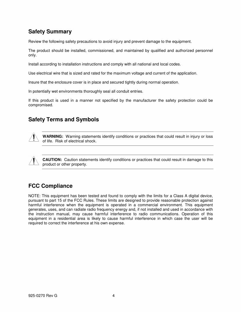
Safety Summary Review the following safety precautions to avoid injury and prevent damage to the equipment. The product should be installed, commissioned, and maintained by qualified and authorized personnel only. Install according to installation instructions and comply with all national and local codes. Use electrical wire that is sized and rated for the maximum voltage and current of the application. Insure that the enclosure cover is in place and secured tightly during normal operation. In potentially wet environments thoroughly seal all conduit entries. If this product is used in a manner not specified by the manufacturer the safety protection could be compromised.
Safety Terms and Symbols
WARNING: Warning statements identify conditions or practices that could result in injury or loss of life. Risk of electrical shock.
CAUTION: Caution statements identify conditions or practices that could result in damage to this product or other property.
FCC Compliance NOTE: This equipment has been tested and found to comply with the limits for a Class A digital device, pursuant to part 15 of the FCC Rules. These limits are designed to provide reasonable protection against harmful interference when the equipment is operated in a commercial environment. This equipment generates, uses, and can radiate radio frequency energy and, if not installed and used in accordance with the instruction manual, may cause harmful interference to radio communications. Operation of this equipment in a residential area is likely to cause harmful interference in which case the user will be required to correct the interference at his own expense.

925-0270 Rev G 5
1.0 Introduction This version of the operator’s manual is intended for C-100 consoles with firmware v2.00 or newer. The BinMaster Model C-100 is a compact control console for a network of BinMaster SmartBob sensors. It can control from 1 to 120 SmartBob sensors with a few keystrokes or automatically by use of an interval timer or external start input signal. It has a 4-20mA current output that, in conjunction with the external start input, provides for a traditional interface to a PLC (programmable logic controller) or DCS (distributed control system) system. The console was designed with a NEMA 4X rating, thus if it is properly installed it will be protected from windblown dust and rain. Vessel configuration is quick and easy with a simple and intuitive user-interface, configurable in either the English or Spanish languages. Measurement formats can be displayed as headroom percentage, headroom height, headroom weight, product percentage, product height and product weight. Vessel configuration and user settings are stored in non-volatile memory and will be retained during a power failure. The Model C-100 can interface with up to five BinMaster C-50 Expansion consoles on a dedicated RS-485 network. The Model C-50 is for interfacing the SmartBob system to a PLC or DCS system. Each Model C-50 expansion console supports up to 6 analog I/O cards, each with 4 ports, for a total of 24 analog I/O ports per C-50. With five C-50’s each SmartBob sensor can have its own I/O port. Each input can be used for externally starting a measurement and each output provides for a 4-20mA current output of the last measurement. For more information on the Model C-50, contact one of BinMaster’s application specialists or go to www.binmaster.com.
2.0 Specifications Power Requirements
Isolated 24VDC source with 2W (0.085A) minimum output. A quality earth connection is also required on the power terminal. Although this is not needed for power or normal operations, it is required for proper protection from lightning and other electrical surges.
SB-485 Port
RS-485 at 2400 bps using BinMaster’s proprietary half duplex protocol A or B and supporting 1 to 120 SmartBob sensors on up to 4,000 feet of a quality twisted-pair shielded cable.
EX-485 Port
RS-485 at 19,200 bps using a proprietary half duplex protocol to communicate to BinMaster Model C-50 expansion consoles on up to 4,000 feet of a quality twisted-pair shielded cable.
External Start Input
Continuous monitoring for a dry contact closure to initiate a measurement with a response time of less than 1 sec.
4-20mA Current Output
Continuous 4 – 20mA current output with 16 bits of resolution into a maximum loop resistance of 700Ω. If weight calculations are DISABLED, the output level is relative to the last measurement of a user-assigned vessel and its entered height. If weight calculations are ENABLED, the output level is relative to the calculated weight of a user-assigned vessel and all its entered parameters. An error condition (did not drop, bob stuck or communications error) can also be presented at this output with a user-selectable value of either 2mA or 22mA.
925-0270 Rev G 6
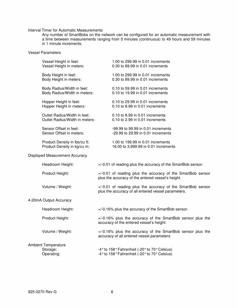
Interval Timer for Automatic Measurements Any number of SmartBobs on the network can be configured for an automatic measurement with a time between measurements ranging from 0 minutes (continuous) to 49 hours and 59 minutes in 1 minute increments.
Vessel Parameters
Vessel Height in feet: 1.00 to 299.99 in 0.01 increments Vessel Height in meters: 0.30 to 89.99 in 0.01 increments Body Height in feet: 1.00 to 299.99 in 0.01 increments Body Height in meters: 0.30 to 89.99 in 0.01 increments Body Radius/Width in feet: 0.10 to 59.99 in 0.01 increments Body Radius/Width in meters: 0.10 to 19.99 in 0.01 increments Hopper Height in feet: 0.10 to 29.99 in 0.01 increments Hopper Height in meters: 0.10 to 8.99 in 0.01 increments Outlet Radius/Width in feet: 0.10 to 8.99 in 0.01 increments Outlet Radius/Width in meters: 0.10 to 2.99 in 0.01 increments Sensor Offset in feet: -99.99 to 99.99 in 0.01 increments Sensor Offset in meters: -29.99 to 29.99 in 0.01 increments Product Density in lbs/cu ft: 1.00 to 199.99 in 0.01 increments Product Density in kg/cu m: 16.00 to 3,999.99 in 0.01 increments
Displayed Measurement Accuracy
Headroom Height: +/-0.01 of reading plus the accuracy of the SmartBob sensor. Product Height: +/-0.01 of reading plus the accuracy of the SmartBob sensor
plus the accuracy of the entered vessel’s height. Volume / Weight: +/-0.01 of reading plus the accuracy of the SmartBob sensor
plus the accuracy of all entered vessel parameters.
4-20mA Output Accuracy
Headroom Height: +/-0.16% plus the accuracy of the SmartBob sensor. Product Height: +/-0.16% plus the accuracy of the SmartBob sensor plus the
accuracy of the entered vessel’s height. Volume / Weight: +/-0.16% plus the accuracy of the SmartBob sensor plus the
accuracy of all entered vessel parameters. Ambient Temperature
Storage: -4° to 158° Fahrenheit (-20° to 70° Celsius) Operating: -4° to 158° Fahrenheit (-20° to 70° Celsius)

925-0270 Rev G 7
Physical Dimensions: 6.5 x 6.3 x 3.5 inches (166 x 160 x 89 mm) Weight: 1.5 lbs (0.7 kg) Enclosure: Polycarbonate, light industrial gray.
Ingress Protection Rating NEMA Type 4x
3.0 Installation
3.1 Mounting When locating a position to mount the C-100 SmartBob control console, make sure to allow for adequate air flow around the unit and don’t place it near any equipment that produces excessive heat. If the ambient temperature of the C-100 is going to exceed 122°F (50°C), consider using a fan of some type to circulate the air. Allowing for good air flow around the C-100 will prolong the life of the unit. Also, to prolong the life of the unit’s enclosure and front panel, avoid a location that would place it in direct and constant sunlight.

925-0270 Rev G 8
3.1.1 Screw Mount There are three screw holes that can be used for mounting the C-100 SmartBob control console as shown in the diagram below. You will need one #8 wood screw at least 3/8” long and two #8 wood screws at least 5/8” long.
1. Locate, drill a hole for and screw the 3/8” long screw into the mounting board/plate, leaving the head of the screw out about 1/8”.
2. Hang the console with the one screw by the center mounting tab. 3. Remove the lower wiring cabinet cover and mark the locations for the two lower mounting screws
with a pencil or awl. 4. Remove the console and drill holes for the two lower mounting screws. 5. Hang the console again by the center mounting tab and fasten in place with the two lower
mounting screws.

925-0270 Rev G 9
3.2 Connections and Wiring A minimum configuration will require a three-wire power connection and a three-wire RS-485 connection to the SmartBob network. Optionally, there may be a two-wire 4-20mA connection, a two-wire external start connection and another three-wire RS-485 connection for the Expansion network. All wiring is fed through water-tight cordgrips and connected inside the lower wiring cabinet to pluggable terminal blocks mounted on the printed circuit board. Remove the two screws on the lower wiring cabinet cover to gain access to the terminal blocks. When wiring is complete, be sure that the lid is properly fastened down for a water and dust-tight seal. Never remove or unscrew the nameplate lid with the keypad and LCD window. There are a total of five terminal blocks but only four cordgrip/entry points inside the wiring cabinet. It is recommended that if all terminal blocks are being used, that the 4-20mA Output (CN3) and the External Start Input (CN4) share the same cordgrip/entry point. All five terminal blocks are capable of supporting 22 to 12 AWG size wires. Be sure to use the appropriate wire gauge/size for the connections and follow all national and local codes concerning this installation. 3.2.1 Power Connection
The power connection (CN8) is a three wire terminal block located on the far right. Two terminal screws marked + and – are for connecting to a 24VDC source, isolated from earth ground. See section 2.0 Specifications for power source requirements. Due to the low power requirements of this console, a 16 or 18 AWG wire would be sufficient for these two power connections. The terminal screw marked with the symbol should be connected to a quality earth for proper protection from lightning and other electrical surges induced in an industrial environment. It is recommended to use a 16 AWG wire or larger for the earth connection and connect it to the closest possible source to earth. It is recommended to use a separate isolated power source for every device on a SmartBob system. This will provide additional protection from lightning and other electrical surges. All three connections at CN8 are required for proper operation and protection of the console.
925-0270 Rev G 10
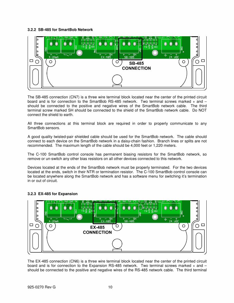
3.2.2 SB-485 for SmartBob Network
The SB-485 connection (CN7) is a three wire terminal block located near the center of the printed circuit board and is for connection to the SmartBob RS-485 network. Two terminal screws marked + and – should be connected to the positive and negative wires of the SmartBob network cable. The third terminal screw marked SH should be connected to the shield of the SmartBob network cable. Do NOT connect the shield to earth. All three connections at this terminal block are required in order to properly communicate to any SmartBob sensors. A good quality twisted-pair shielded cable should be used for the SmartBob network. The cable should connect to each device on the SmartBob network in a daisy-chain fashion. Branch lines or splits are not recommended. The maximum length of the cable should be 4,000 feet or 1,220 meters. The C-100 SmartBob control console has permanent biasing resistors for the SmartBob network, so remove or un-switch any other bias resistors on all other devices connected to this network. Devices located at the ends of the SmartBob network must be properly terminated. For the two devices located at the ends, switch in their NTR or termination resistor. The C-100 SmartBob control console can be located anywhere along the SmartBob network and has a software menu for switching it’s termination in or out of circuit. 3.2.3 EX-485 for Expansion
The EX-485 connection (CN6) is a three wire terminal block located near the center of the printed circuit board and is for connection to the Expansion RS-485 network. Two terminal screws marked + and – should be connected to the positive and negative wires of the RS-485 network cable. The third terminal

925-0270 Rev G 11
screw marked SH should be connected to the shield of the RS-485 network cable. Do NOT connect the shield to earth. These three connections at this terminal block are optional and only needed when connecting BinMaster C-50 expansion units to the system. A good quality twisted-pair shielded cable should be used for the RS-485 network. The cable should connect to each device on the network in a daisy-chain fashion. Branch lines or splits are not recommended. The maximum length of the cable should be 4,000 feet or 1,220 meters. This port has built-in line biasing and termination. 3.2.4 External Start Input
The External Start connection (CN4) is a two wire terminal block located towards the left of the printed circuit board. It is identified with CN4 and an open switch symbol. These two terminal screws are polarity independent and are intended only for a dry contact closure, such as a relay output from a PLC or a pushbutton switch. This connection does not source or sink any negligible amount of current so a quality twisted-pair cable of 20 to 22 AWG wiring is sufficient. A shielded cable is not required; however, if one is used leave the shield un-connected at the console. The External Start connection is optional and only needed when a PLC/DCS or remote pushbutton switch is needed to initiate a measurement. This input can only trigger one SmartBob sensor but can be assigned to any one on the network. This input is negative edge-triggered, meaning the dry contact must be cycled open and then closed again to initiate a new measurement.

925-0270 Rev G 12
3.2.5 4-20mA Output
The 4-20mA Output connection (CN3) is a two wire terminal block located on the far left of the printed circuit board. It is identified with CN3 and labeled with 4-20. The two terminal screws marked + and – should be connected to the proper positive and negative wires of the load. This output is powered and capable of driving up to a 700Ω loop. Depending on the distance this wiring must go, a quality twisted-pair cable of 18 to 22 AWG wiring is sufficient. A shielded cable is not required; however, if one is used leave it un-connected at the console. The 4-20mA Output connection is optional and only needed when a 4-20mA output is needed to feed a PLC or DCS system of the last measurement taken. This output can only represent one SmartBob measurement but can be assigned to any SmartBob sensor on the network.
3.3 RS-485 Network Requirements Both the SmartBob network (SB-485) and the Expansion network (EX-485) use RS-485 wiring and data signaling techniques and must meet certain criteria for reliable operation. If these criteria are not met, communications errors will most likely occur and result in failed measurements. Troubleshooting communications errors can be expensive and time consuming, so BinMaster strongly encourages you to take adequate time in understanding and installing the RS-485 networks and to use quality cabling and connection techniques. Summary of RS-485 requirements for BinMaster products:
• All devices must be wired or connected in a daisy-chain fashion.
• Use a quality twisted-pair cable with shield.
• Maintain correct polarity between all devices wired to the network cable.
• The two ends of the network cable must be terminated.
• Biasing must be applied in only one place anywhere along the cable or network.
• All devices on the network must support and be configured for the same protocol.
925-0270 Rev G 13
Wiring
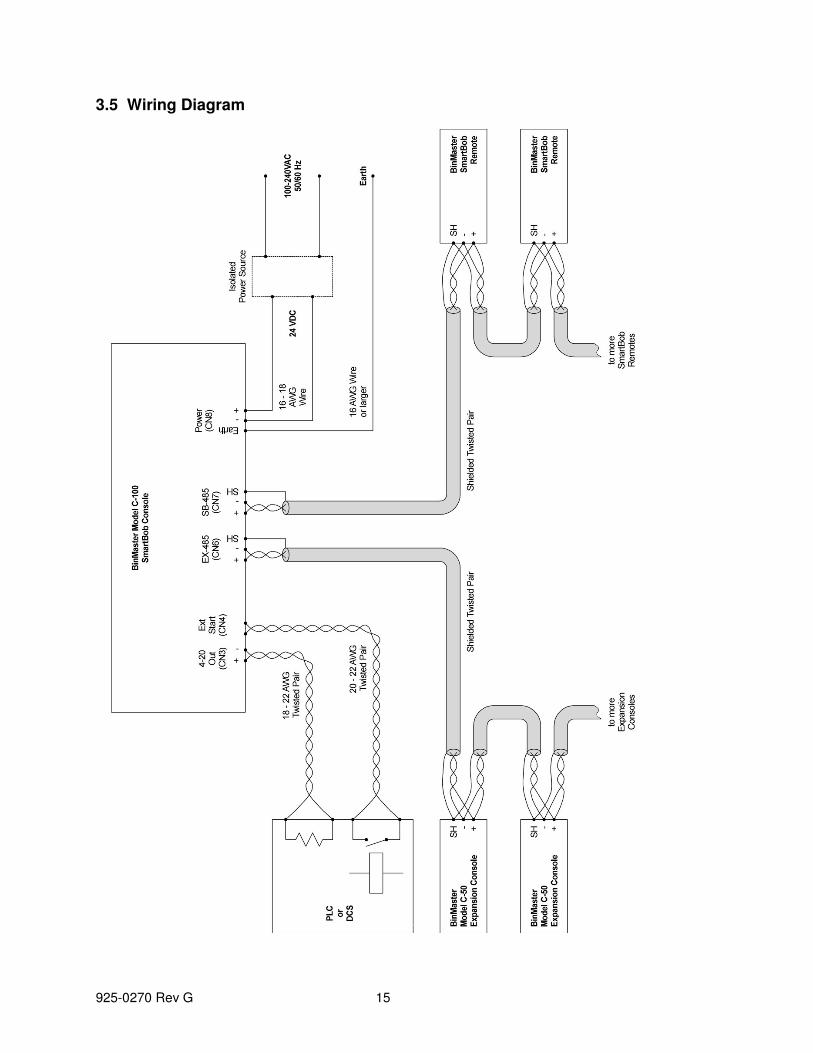
All devices on an RS-485 network must be connected directly to the network cable with no splits, taps or branch lines. The overall length of the cable must not exceed 4,000 feet or about 1,220 meters. Use a quality twisted-pair cable with shield and connect as per the wiring diagram in section 3.5. Observe the polarity of the wiring between all devices on the network, making sure that the wire connected to the + terminal at the C-100 SmartBob control console is also connected to the + terminal on all other devices. Likewise, make sure that the wires connected to the – and SH terminals at the C-100 SmartBob control console are also connected to the – and SH terminals, respectively, on all other devices. Do not connect the wires or shield to anything other than that specified.
Termination
All BinMaster RS-485 networks must be terminated at both ends with a 120Ω resistor for proper operation and reliability. Normally this is done by the two devices connected at the very ends of the network cable. On some devices the termination is set ON or OFF by a slide switch labeled “NTR” and on other devices this may be set IN or OUT of circuit through a software menu. The C-100 console uses a software menu titled “SB-485 Termination” for switching the termination resistor IN or OUT on the SB-485 port. For the EX-485 port, the C-100 console has the termination resistor permanently switched in and therefore the C-100 console must be located at one end of the network. Refer to the manual of the other devices for instructions on how to switch their termination.
Bias Resistors
All BinMaster RS-485 networks must have bias resistors installed or switched in for proper operation and reliability. This must be done at only one device but anywhere along the network cable. The C-100 SmartBob control console has bias resistors permanently switched in for both the SB-485 port and the EX-485 port, so for all other devices connected to either of these networks make sure that the bias resistors are turned OFF or switched OUT of circuit. Refer to the manual of these other devices for instructions on how to do so.
Protocol
All devices on an RS-485 network must be configured to use the same protocol. BinMaster supports two protocols for the SmartBob network. Protocol A is newer, more reliable and more efficient while protocol B is older and supported for legacy products. It is recommended to use protocol A if all the devices on the SmartBob network support it; otherwise use protocol B. Depending on the device, selecting the SmartBob protocol may be done with a switch, a jumper position or a software menu. The C-100 SmartBob control console uses a software menu titled “SB-485 Protocol” for configuration between SmartBobs protocol A or B. Refer to the manual of the other devices for instructions on how to set or configure their SmartBob protocol.

925-0270 Rev G 14
3.4 Lightning/Surge Protection All electronic devices connected to a large wired network are susceptible to damage from lightning and other sources of electrical surges. Both the power source and an RS-485 network are a means for electrical surges to enter the C-100 SmartBob control console and do damage. Although some level of protection from electrical surges is built into the C-100 SmartBob control console, there are options to further protecting your investment.
1. As recommended for the power connection at CN8, use an isolated power source and verify that the output is NOT grounded or referenced to earth. Make sure that all devices connected to either the SmartBob network or Expansion network uses a separate power source.
2. Be sure to connect the terminal at CN8 marked to a good quality earth using a 16 AWG size wire or larger. This wire should be as short as possible to earth with no sharp bends or loops in the wiring.
3. Use additional external lightning/surge arrestors on the RS-485 networks. This is very critical of large outdoor networks that are high off the ground. Place 1 to 3 surge arrestors on the RS-485 network evenly spaced apart, following the manufacturer’s installation instructions and using a good quality connection to earth.
4. Consider using BinMaster wireless solutions that not only greatly protect your investment from lightning but can reduce installation time and eliminate the need for running long lengths of RS-485 cable. Call BinMaster and speak with one of our applications specialist for more information on our wireless solutions.
925-0270 Rev G 15
3.5 Wiring Diagram

925-0270 Rev G 16
4.0 Operation and Setup The C-100 SmartBob control console is controlled and operated through the use of a 6-button icon-based keypad and a simple intuitive text-based menu system. The menu system is user-selectable in either the English or Spanish languages.
4.1 Keypad The keypad consists of 6 membrane style keys appearing as shown to the right. Four of them are labeled with left, right, up and down arrow keys and are used for navigating menu selection bars and character cursors. Another key is labeled with a (cross out) for cancel or escape and is generally used to stop an action or to exit a screen without taking action. The final key is labeled with a (check mark) for Ok and is generally used to accept the current selection and/or to advance to the next screen. Most operations will simply require a single press and release of a key; however some operations may benefit from a key being held. For instance, holding the up or down arrow keys will allow the user to continuously scroll through long lists of vessel measurements. In some menus, the left and right arrow keys serve as a page up and page down key for faster navigation through long lists. Also, in some menus with long lists, you can press the left and up arrow keys simultaneously for a jump to the top of the list and pressing the right and down arrow keys simultaneously for a jump to the bottom of the list.
4.2 Menu System Each menu and/or screen maintains a common format for ease of understanding and use. The example screen below shows a few of the common items found on most screens.
Scroll Up Indicator
Scroll Down Indicator
Selection Bar
Menu/Title Bar
Setting Indicator
The Menu/Title Bar will always be present at the top and identify the current menu or screen to the user. Below that will be up to three lines of text or selection items, depending on the current menu or screen. The Selection Bar is repositioned vertically with the / keys and is used for making a selection in a menu. Normally a selection isn’t accepted until the key is pressed. The Setting Indicator, displayed as a check mark towards the left of the screen, is used in various places under the Setup Menu to indicate current or active settings.

925-0270 Rev G 17
The Scroll Up and Down Indicators, displayed as little up and down arrows towards the right of the screen, will be present when more selections or information is available off screen. The Scroll Up Indicator will be present when the user can scroll up to obtain more selections or information and the Scroll Down Indicator will be present when the user can scroll down to obtain more selections or information. Navigating through the menu system is straight-forward, position the selection bar on the desired menu or selection item and press the key. To go back a menu or escape from the current screen, press the key. The menu system is structured as shown in the following diagram.
Main Menu Measure/View
Setup SB-485 Protocol
SB-485 Termination
Auto Add/Remove
Add/Remove
Units of Measure
C-50 Setup
I/O Assignment
4-20mA Output
4-20mA Error
Interval Timer
Access Code
Language/Idioma
Vessel Setup
Weight Calculations
Measurement Format
Measure All
001
Info/About
Capacity
Headroom
Product
002 Capacity
Headroom
Product
more... up to 120
Measurement Type

925-0270 Rev G 18
4.2.1 Main Menu The Main menu has two selections: Measure/View and Setup. Select Measure/View if you want to take an immediate measurement or view the results of the last measurement. Select Setup if you need to change user display preferences, setup vessel parameters, SmartBob network settings or configure the Expansion network. The main menu is at the top of the menu system, so pressing the key here will have no effect. 4.2.2 Measure/View The Measure/View menu provides a full listing of all the last measurement results and a means to initiate a measurement. It will always have at least two selections. The first selection will always be Measure All and selecting it will immediately start a measurement process on all configured SmartBob sensors. The second selection and any following selections will contain the last measurement data next to its associated SmartBob address. Note that SmartBob sensors are identified by their address and are always displayed with three digits ranging from 001 to 120. Selecting any of the measurement data will bring up the details screen for that SmartBob. If there is only one SmartBob sensor configured on the network then there will only be two selections in this menu. If you have multiple SmartBob sensors configured, then you can scroll through this menu to see them all. The title bar will also indicate whether the measurement data is of the headroom (Hdrm) or of the product (Prod), as set under Measurement Format. Note that ‘headroom’ refers to the upper empty space in the tank and ‘product’ refers to the lower filled space. The details screen displays additional data for a particular SmartBob and provides a means to take a measurement with that particular SmartBob by pressing the key. Use the / keys to cycle through all the data (capacity, headroom and product) for the selected vessel and SmartBob. In each mode, the percentage and height are displayed, as is volume or weight if weight calculations are enabled. If the vertical scroll indicators are present, the operator can scroll to other SmartBob measurement results. The accuracy of these readings is dependent on both the SmartBob reading and the vessel parameters entered into Vessel Setup. 4.2.3 Setup The Setup menu has selections for setting user preferences, configuring the SmartBob network, the Expansion network and defining SmartBobs and associated vessels. All settings and configurations made will be retained during a loss of power. SB-485 Protocol
This is a menu for setting which communications protocol to use on the SmartBob network, the operator can choose A or B. The default setting is A. All devices on the SmartBob network must be configured to use the same protocol. Protocol A is newer, more reliable and more efficient while protocol B is older and supported for legacy products. It is recommended to use protocol A if all the devices on the SmartBob network support it; otherwise use protocol B. The protocol must be configured prior to running Auto Add/Remove or any measurement process. See the SBRII or SB-TS1 manual for their protocol jumper settings.
925-0270 Rev G 19
SB-485 Termination
This is a menu for setting whether the SmartBob network termination is switched In or Out of the network. If the console is the final device connected at either end of the SmartBob network choose In, otherwise choose Out. The default setting is In. The termination must be set prior to running Auto Add/Remove or any measurement process.
Auto Add/Remove
This is a process the operator can choose to let the console automatically scan and detect any SmartBob sensors on the network. After selecting Auto Add/Remove, it will begin searching for SmartBob sensors currently connected to the network, adding or removing them from the working list. If there are existing SmartBobs enabled, a confirmation screen will appear to make sure you want to re-scan for new and removed SmartBob sensors. Press to cancel or to confirm. The operator can choose to let it scan all the way to 120 or stop it once they feel it has found them all. Since this process uses SB-485 communications, make sure that SB-485 Protocol and SB-485 Termination have previously been set.
Add/Remove
This is a menu that allows the operator to manually add or remove SmartBob sensors to the console’s working list. Use the , and keys to select and accept one or more SmartBob addresses from the list to be configured for use. After all desired addresses are assigned, use the key to exit.
Units of Measure
This is a menu for selecting the units used for entering vessel dimensions and product density in Vessel Setup. It also determines the units used for readings when Measurement Format is set for Height or Cubic Units. If weight calculations are enabled, your two choices are English (ft, lbs) or Metric (m, kg) with the default being English (ft, lbs). If weight calculations are disabled, your two choices are Feet (ft) or Meters (m) with the default being Feet (ft). Changing this setting will convert all stored vessel parameters from one system to the other.
Weight Calculations
This is a menu for enabling or disabling volume and weight calculations. The default is disabled. By enabling weight calculations, the operator will be able to view measurement results as a volume or weight in various units. The option to disable this feature is provided due to the complexity of entering vessel parameters that may not be needed on some systems. This setting will have an effect on the following:
1. The amount of data to be entered under Setup > Vessel Setup. 2. Selections available under Setup > Measurement Format. 3. Data presented under Measure/View. 4. Data represented by the 4-20mA output.
Vessel Setup
This is a menu for entering the vessel parameters associated with the SmartBob addresses previously configured in Add/Remove or Auto Add/Remove. Defining vessels accurately is critical in obtaining accurate measurement data of weight or product height.
925-0270 Rev G 20
If weight calculations are disabled, this is simply for setting the overall height of the vessel, sensor offset and maximum drop. The first screen is for selecting the vessel(s) to be configured, the second screen is for entering the vessel height of the selected vessel(s), the third screen is for setting a headroom offset and the fourth for setting maximum drop distance.
Vessel Selection – This is for selecting which vessel or vessels to configure parameters for, choose either Set All or one particular vessel. If all vessels are to be the same or similar use Set All, otherwise configure one at a time. Vessel Height – For setting the overall height of the vessel. Sensor Offset – For setting the offset or distance between the sensor and the full mark. A positive value places the sensor below the full mark or down in the tank. A negative value places the sensor above the full mark or up outside the tank. SmartBob Max Drop – For setting the maximum drop distance the SmartBob will drop its probe. If set to some value less than the height of the vessel, it would prevent the SmartBob from dropping its probe down through the hopper outlet and into an auger. Note: This feature is only available when configured for protocol A and will not function properly unless the SmartBob contains firmware v2.8 or newer. Due to detection time within the SmartBob itself, it may actually drop up to 1.5 inches more than this setting.
If weight calculations are enabled, this is a multi-page menu for entering vessel parameters and product density required in calculating weight. Following is a listing of the different Vessel Setup pages and a process flowchart.
Vessel Selection – See description above. Vessel Shape – For setting the shape of the previously selected vessel(s), choose between circular or rectangular. Body Height – For setting the height of the vessel’s body. Note that this is just the main body of the vessel and not the overall height. Body Radius – For setting the radius of a circular vessel’s body. Body Width 1 & Body Width 2 – For setting the two widths of a rectangular vessel’s body. Hopper Present – Choose between Yes or No on whether a hopper is present. Hopper Height – For setting the height of the hopper, if it exists. Outlet Radius – For setting the radius of a circular hopper’s outlet, if a hopper exists. Outlet Width 1 & Outlet Width 2 – For setting the two widths of a rectangular hopper’s outlet, if a hopper exists. Sensor Offset – See description above. Product Density – For setting the weight density of the product or contents of the vessel. SmartBob Max Drop – See description above.

925-0270 Rev G 21
Body Height
Body Radius Body Width 1
Body Width 2
Hopper Present
Vessel Shape
Body Height
Hopper Present
Rectangular
Hopper Height
Outlet Radius
Hopper Height
Outlet Width 1
Outlet Width 2
SensorOffset
Yes Yes
No No
Select Vessel(s)to Edit
Circular
ProductDensity
C-50 Setup This is a menu for automatic setup of Model C-50’s connected to the expansion port (EX-485). The operator can choose between Enabled and Disabled. The operator must use Add/Remove or Auto Add/Remove prior to making this selection. The default setting is Disabled. After the user selects Enabled, the C-100 console will automatically assign available I/O’s to enabled SmartBobs and then enter the I/O Assignment menu for the user to review and/or reassign if necessary.

925-0270 Rev G 22
I/O Assignment
This is a menu for assigning SmartBob sensors to I/O ports. The operator must use Add/Remove or Auto Add/Remove prior to using this menu. This menu will differ depending on whether the C-50 Setup was enabled or disabled. If C-50 setup is disabled, then this menu will be for assigning any single SmartBob sensor to the C-100’s onboard I/O (External Start input and 4-20mA output). The operator simply selects the address of any single SmartBob sensor in this list, but it defaults to the first address available in the list. If C-50 setup is enabled, then the operator will use this menu for viewing the current assignments between multiple SmartBob sensors and multiple I/O ports located on the C-50 network. On the left is the address of the SmartBob sensor and to its right is the I/O port that is assigned to it. The I/O port is displayed in the format c:s:p, where c is the expansion console’s address (1 to 5), s is the slot/card position (0 to 5) and p is the slot/card’s port (0 to 3). For additional information on addressing, slots/cards and ports, please refer to the Model C-50 Operators Manual. To reassign the I/O port of a particular SmartBob sensor, position the selection bar on the address of that SmartBob sensor to be changed and press . This will display another menu for assigning a different I/O port to that SmartBob sensor. The operator can choose to unassign a SmartBob address or reassign to any I/O port listed in this menu; however, only I/O ports that are currently available and unassigned will be listed. To swap the assignments of two SmartBob sensors already assigned to I/O ports, you must first unassign one of them, then reassign the second one and finally go back and reassign the first one.
4-20mA Output
This is a menu for setting what the 4-20mA Output will represent; the operator can choose between Product and Headroom. The default setting is Product. When weight calculations are disabled, this output is a percentage of the headroom height or product height. When weight calculations are enabled, this output is a percentage of the headroom weight or product weight.
4-20mA Error
This is a menu for setting what the 4-20mA output error level will be, the operator can choose between 2mA and 22mA. This error level will be programmed to the output whenever the last measurement produced an error condition such as a communications error or Bob is stuck. The default setting is 22mA.
Interval Timer
The interval timer allows the operator to enable and configure the console to take multiple automatic timed measurements. The selections are On/Set and Off. The default setting is Off. After selection of On/Set, a setup screen appears for entering the timer value in hours and minutes. Enter any amount of time from 0 minutes (continuous) to 49 hours and 59 minutes in the format: HH:MM. One minute would be 00:01 and 24 hours would be 24:00. The timer is adjusted one digit at a time. Use the /

925-0270 Rev G 23
keys to select a digit by repositioning the cursor and the / keys to adjust the selected digit. Once all four digits have been entered, press the key. After the interval time has been set, a menu appears for assigning SmartBobs to the automatic measurement process. At least one must be assigned and up to all SmartBob sensors configured may be assigned. Use the , and keys to select and accept one or more SmartBob address’ from the list to the interval timer. After all desired SmartBob sensors are assigned, press the key to exit.
CAUTION: Setting the interval timer value to 00:00 (continuous) may decrease the life cycle of the SmartBob sensors assigned to the interval timer.
Measurement Format
This is a menu for selecting the measurement format displayed under the Measure/View menu. When weight calculations are disabled, only Percent and Height are available. When weight calculations are enabled, the operator can select between the following:
• Percent
• Height
• Cubic Units
• U.S. Gallons
• U.S. Bushel
• Liters
• Pounds
• Tons
• Kilograms
• Metric Tons
Height and Cubic Units will be dependent on the setting in Units of Measure, with units in either feet (ft) or meters (m). Note that this setting effects what is displayed in Measure/View and Measure/View Details.
Access Code
This menu allows the operator to enable and set a 4-digit code for access to the Setup menu. The selections are On/Set and Off. The default setting is Off. After selection of On/Set, a setup screen appears for entering a 4-digit number. Enter any 4-digit number between 0000 and 9999, one digit at a time. Use the / keys to re-position the cursor and the / keys to adjust the selected digit. After all four digits have been entered, write the number down in a safe place and press the key. Next time the Setup menu is accessed, this same screen is presented for entering the access code. Entry to the Setup menu is not permitted until the correct 4-digit code is entered. With an access code set, if the console is left unattended in the Setup menu it will automatically exit to the Main menu after 20 seconds of no keypad activity.
925-0270 Rev G 24
CAUTION: If you lose or forget the access code you will have to clear ALL nonvolatile memory to regain access to the Setup menu. Doing so will also erase all user settings, vessel parameters and measurement data. To clear all nonvolatile memory, press and hold both the and keys while either pressing S1 inside the wiring cabinet or power cycling the console.
Language/Idioma
This is a menu that allows the operator to select either the English or Spanish language for displaying the text-based menu system. The default is English. This menu is also presented to the user when the C-100 SmartBob control console is powered up for the very first time.
Info/About
This screen simply displays company, product and firmware version information. Knowing the firmware version may be needed when working with BinMaster’s service department. This information is also displayed momentarily when powering up.
4.3 Messaging System The Model C-100, with firmware version 1.06 and newer, has a messaging system that, if certain conditions are met, will display an important message to the operator. This message may remain visible until the conditions that caused it are corrected or until the user presses the key. “One or more enabled expansion consoles are offline.”
This message will be displayed if C-50 setup is enabled and one or more previously detected C-50 expansion consoles are not responding to communication requests. The operator should verify all Expansion network wiring and that all C-50s on the network are powered.
“One or more assigned expansion outputs are disconnected.”
This message will be displayed if C-50 setup is enabled and one or more 4-20mA outputs, which are assigned to a SmartBob sensor, are disconnected. The operator should verify that all assigned 4-20mA outputs on all C-50s expansion consoles are properly connected to their appropriate PLC input or load. Status LEDs on the C-50 expansion console should further assist in identifying the disconnected output. For additional information, refer to the Model C-50 Operators Manual.
925-0270 Rev G 25
5.0 Warranty and Service
5.1 Limited Warranty BinMaster warrants this product against defects in material and workmanship for two (2) years according to the following terms:
1.) This warranty extends to the original purchaser only and commences on the date of original purchase. 2.) BinMaster’s sole obligation under said warranty is to repair, or at its option replace the defective parts. The buyer shall have no other remedy. All special, incidental and consequential damages are excluded. The buyer must deliver the product under warranty prepaid to the factory. BinMaster’s obligation is limited to the cost of material and labor to repair or replace, and does not include transportation expenses. 3.) This warranty shall be voided, in our sole judgment, by alterations of equipment except by BinMaster, or tampering with, improper installation or maintenance, accident or misuse, or act of God. This warranty expressly excludes all damage to the product resulting from careless or neglectful packaging or transportation. The warranty does not extend to repairs made necessary by normal wear. 4.) This warranty is in lieu of all other warranties, expressed or implied including any implied warranties or merchantability or fitness for particular purpose. No employee, agent, franchise dealer or other person is authorized to give any warranties of any nature on behalf of BinMaster. 5) BinMaster shall in no event be responsible for any warranty work done without first obtaining BinMaster’s written consent. 6) Except as provided herein, BinMaster shall have no liability, loss or damage caused or alleged to be caused directly or indirectly by this equipment. 7) This warranty gives the buyer specific legal rights, and you may also have other rights which vary from state to state. 8) For service, please call 402-434-9102.
5.2 Technical Support, Customer Service and Repair If you are in need of an updated operator's manual, specification drawing or parts replacement list, please visit our online documentation at www.binmaster.com. Prior to shipping your Model C-100 back for repair, please call our service department for an RMA number. Along with the RMA number, you will also be provided with shipping instructions and address. You may call the customer service department for technical support, application assistance and to receive an RMA Monday through Friday from 8:00 am to 5:00 pm Central Time. BinMaster, a division of Garner Industries, offers a toll-free telephone number (800) 278-4241 to our customer service department. International customers can call us at (402) 434-9102 or reach us via fax at (402) 434-9133.
925-0270 Rev G 26
6.0 Disposal This product consists of materials that may be recycled by certain recycling companies. It uses recyclable materials and is designed to be easily separated. Consult local authorities for proper disposal locations.

925-0270 Rev G 27
Declaration of Conformity BinMaster Level Controls 7201 North 98th Street Lincoln, NE 68507-9741 Phone: 402-434-9100, Fax: 402-434-9133 BinMaster declares that all models of the SBR II level control devices as listed below comply with the following directives and harmonized standards. This product if installed, operated and maintained as described in this manual will provide a safe and reliable level measurement device for a variety of materials.
EMC Directive 2004/108/EC Standard EN 61326-1:2006
Product: Industrial console for a network of SmartBob sensors. Models: C-100 All test reports and documentation are held and can be obtained from BinMaster. Manufacturing Location: Lincoln, Nebraska, USA
Scott McLain President 4/8/2010