Model-based development of ARINC 653 using UML …€¦ · A notation capable to handle networks of...
41
1 © 2011 Atego. All Rights Reserved. © 2011 Atego. All Rights Reserved. Model-based development of ARINC 653 using UML and SysML Andreas Korff, Atego – OMG RT Workshop, Paris, 18.04.2012
Transcript of Model-based development of ARINC 653 using UML …€¦ · A notation capable to handle networks of...

1 © 2011 Atego. All Rights Reserved. © 2011 Atego. All Rights Reserved.
Model-based development of ARINC 653 using UML and SysML
Andreas Korff, Atego – OMG RT Workshop, Paris, 18.04.2012
2 © 2011 Atego. All Rights Reserved.
Agenda
Motivation of Integrated Modular Systems
Modelling Notation Standards UML and SysML
Applying UML and SysML to IMS
ARINC 653
Using Models to support ARINC 653
Conclusion
3 © 2011 Atego. All Rights Reserved.
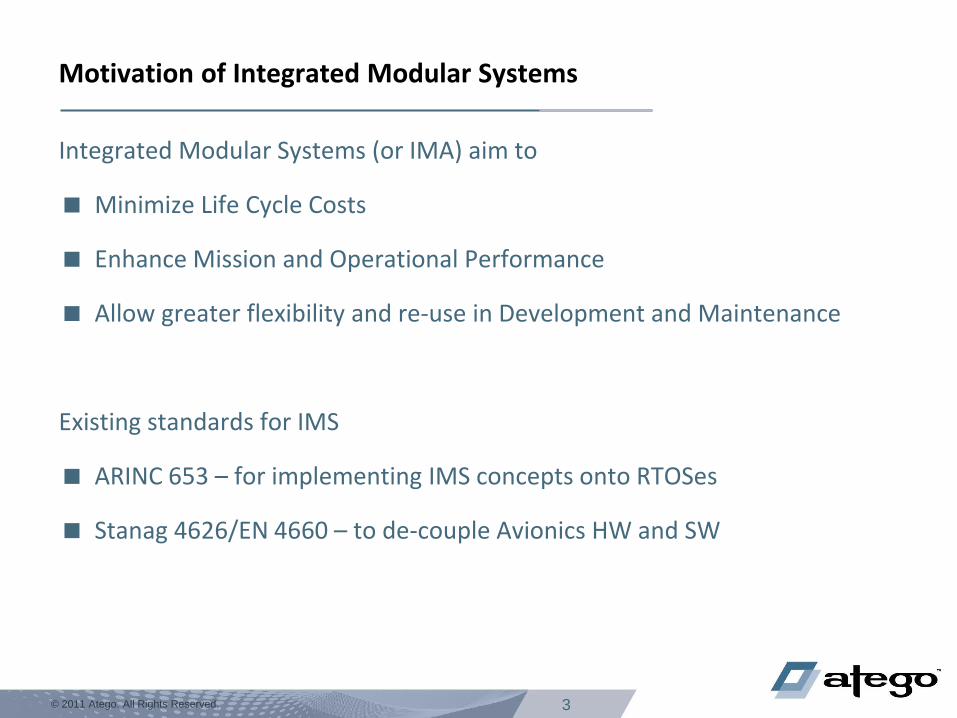
Motivation of Integrated Modular Systems
Integrated Modular Systems (or IMA) aim to
Minimize Life Cycle Costs
Enhance Mission and Operational Performance
Allow greater flexibility and re-use in Development and Maintenance
Existing standards for IMS
ARINC 653 – for implementing IMS concepts onto RTOSes
Stanag 4626/EN 4660 – to de-couple Avionics HW and SW
4 © 2011 Atego. All Rights Reserved.
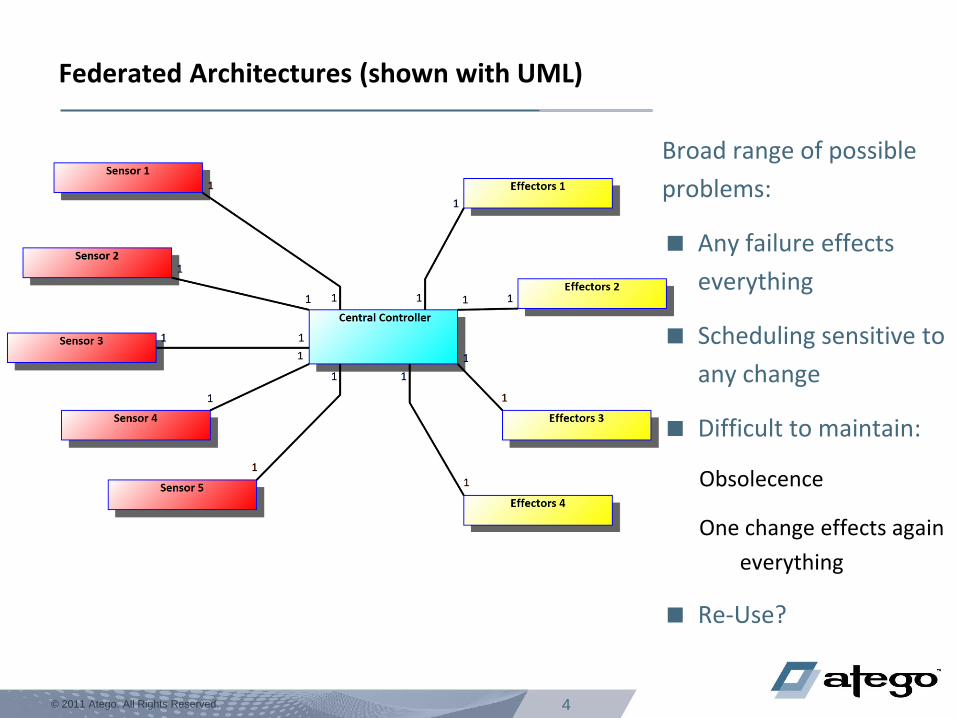
Federated Architectures (shown with UML)
Broad range of possible
problems:
Any failure effects
everything
Scheduling sensitive to
any change
Difficult to maintain:
Obsolecence
One change effects again
everything
Re-Use?
5 © 2011 Atego. All Rights Reserved.
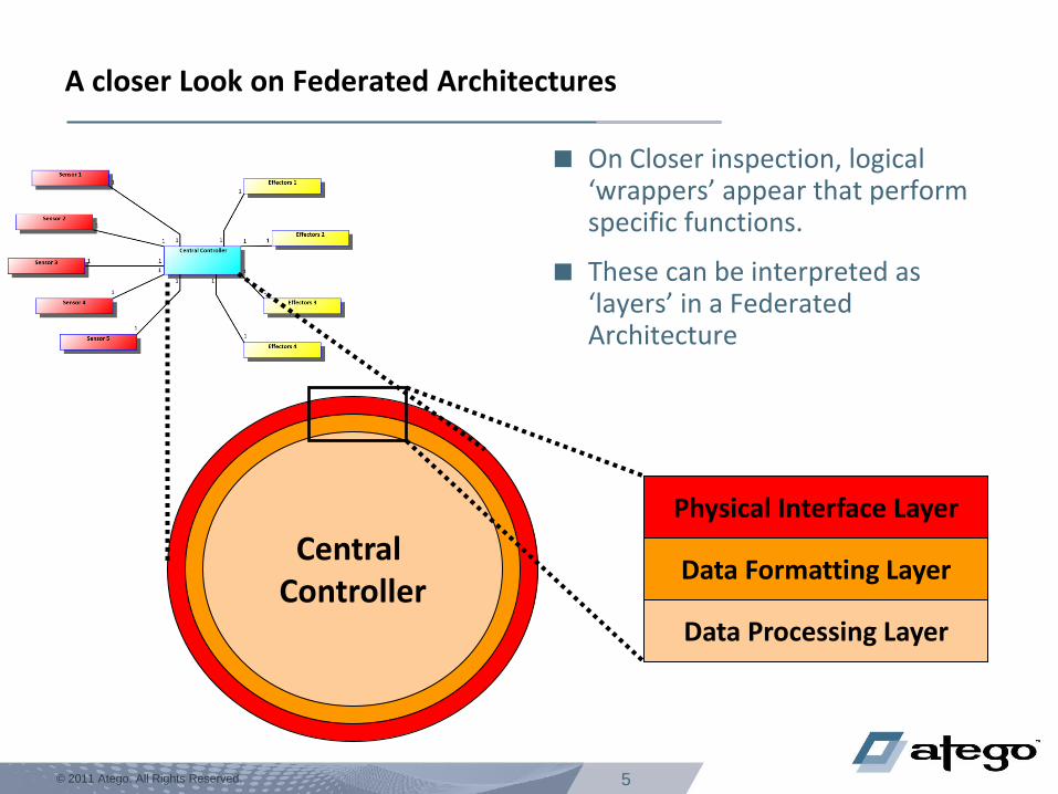
A closer Look on Federated Architectures
On Closer inspection, logical ‘wrappers’ appear that perform specific functions.
These can be interpreted as ‘layers’ in a Federated Architecture
Central Controller
Physical Interface Layer
Data Formatting Layer
Data Processing Layer
6 © 2011 Atego. All Rights Reserved.
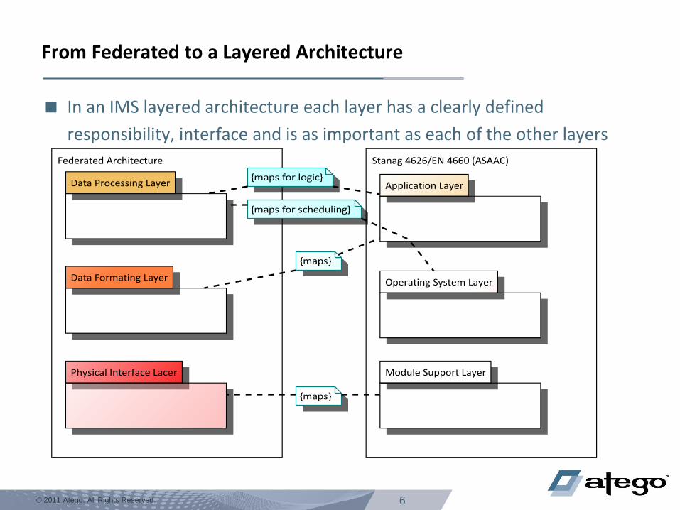
From Federated to a Layered Architecture
In an IMS layered architecture each layer has a clearly defined
responsibility, interface and is as important as each of the other layers
Physical Interface Lacer
Data Formating Layer
Data Processing Layer Application Layer
Operating System Layer
Module Support Layer
Federated Architecture Stanag 4626/EN 4660 (ASAAC)
{maps for logic}
{maps for scheduling}
{maps}
{maps}
7 © 2011 Atego. All Rights Reserved.
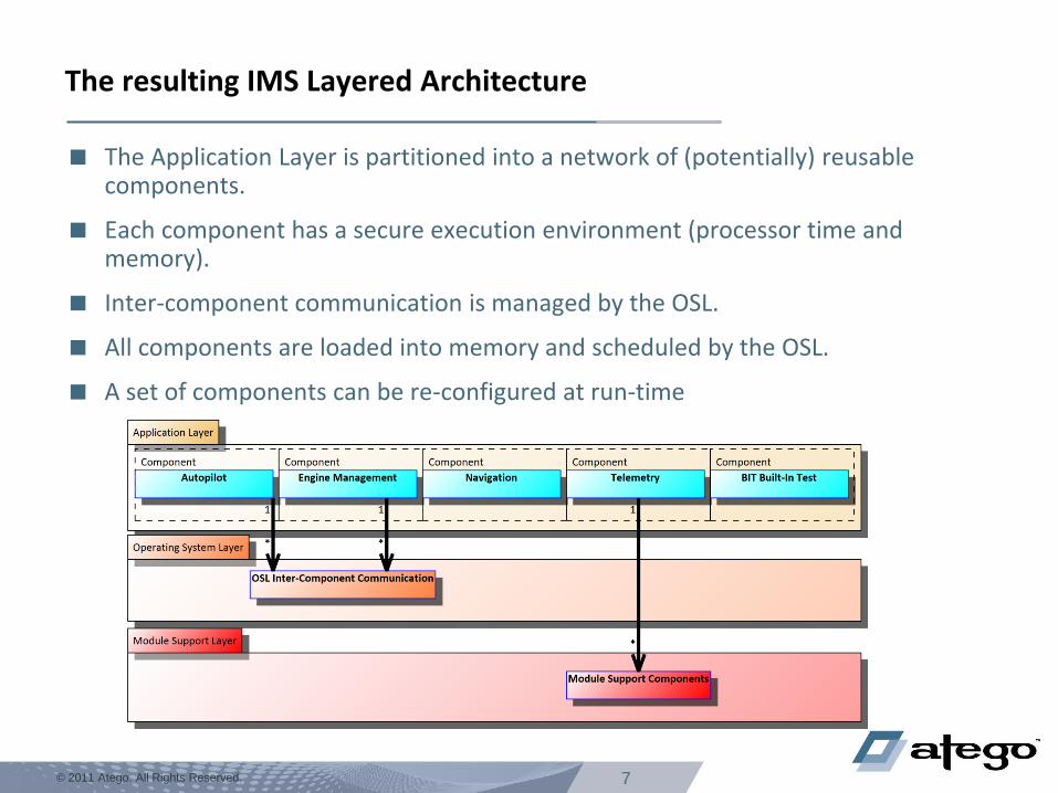
The resulting IMS Layered Architecture
The Application Layer is partitioned into a network of (potentially) reusable components.
Each component has a secure execution environment (processor time and memory).
Inter-component communication is managed by the OSL.
All components are loaded into memory and scheduled by the OSL.
A set of components can be re-configured at run-time
8 © 2011 Atego. All Rights Reserved.
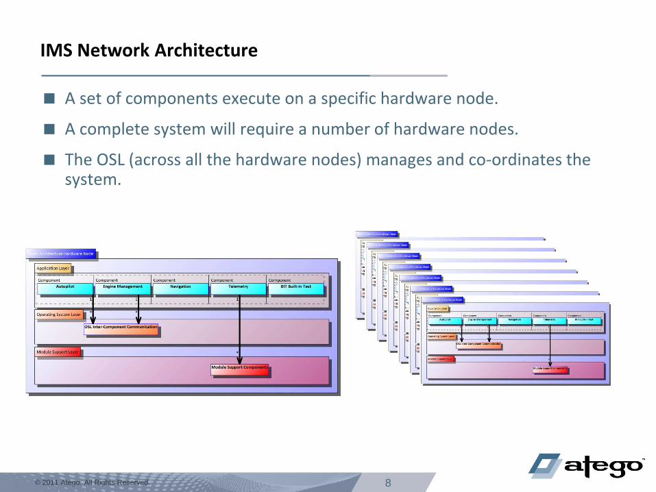
IMS Network Architecture
A set of components execute on a specific hardware node.
A complete system will require a number of hardware nodes.
The OSL (across all the hardware nodes) manages and co-ordinates the system.
9 © 2011 Atego. All Rights Reserved.
IMS Reconfiguration
The allocation of components to hardware nodes is not static at run-time.
The failure of a critical component on one hardware node will cause it to be re-
deployed to another hardware node.
The failure of one Hardware Node will cause all components to be re-deployed.
Changes in Mission may also cause a reconfiguration.
10 © 2011 Atego. All Rights Reserved.
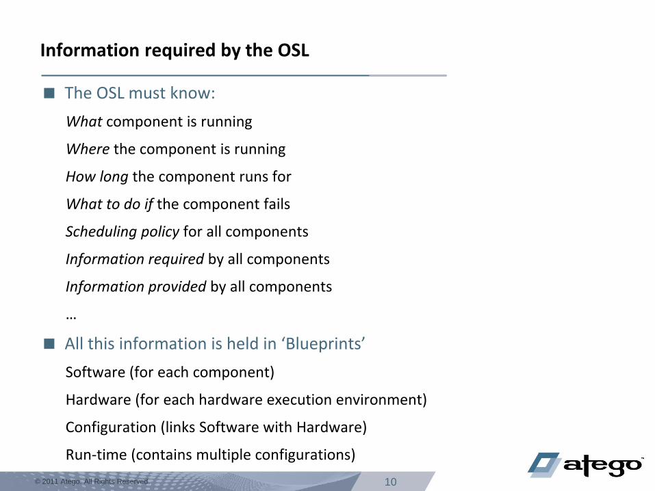
Information required by the OSL
The OSL must know:
What component is running
Where the component is running
How long the component runs for
What to do if the component fails
Scheduling policy for all components
Information required by all components
Information provided by all components
…
All this information is held in ‘Blueprints’
Software (for each component)
Hardware (for each hardware execution environment)
Configuration (links Software with Hardware)
Run-time (contains multiple configurations)
12 © 2011 Atego. All Rights Reserved. © 2011 Atego. All Rights Reserved.
Modelling Network Architectures
13 © 2011 Atego. All Rights Reserved.
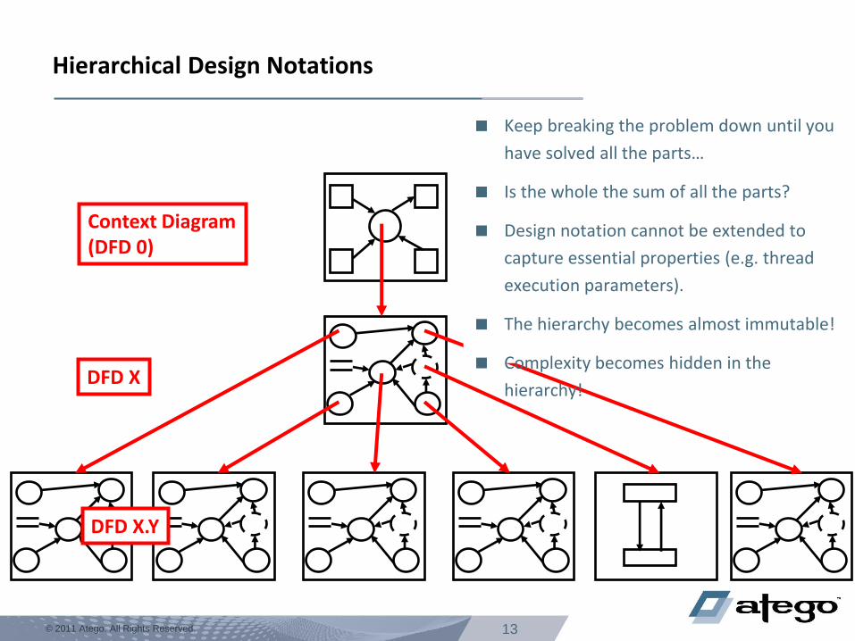
Hierarchical Design Notations
Context Diagram (DFD 0)
DFD X
DFD X.Y
Keep breaking the problem down until you
have solved all the parts…
Is the whole the sum of all the parts?
Design notation cannot be extended to
capture essential properties (e.g. thread
execution parameters).
The hierarchy becomes almost immutable!
Complexity becomes hidden in the
hierarchy!
14 © 2011 Atego. All Rights Reserved.
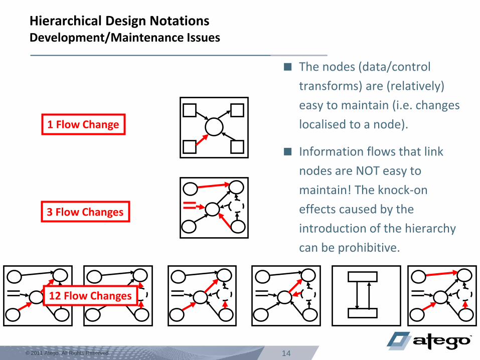
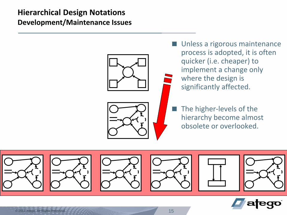
Hierarchical Design Notations Development/Maintenance Issues
The nodes (data/control
transforms) are (relatively)
easy to maintain (i.e. changes
localised to a node).
Information flows that link
nodes are NOT easy to
maintain! The knock-on
effects caused by the
introduction of the hierarchy
can be prohibitive.
1 Flow Change
3 Flow Changes
12 Flow Changes
15 © 2011 Atego. All Rights Reserved.
Hierarchical Design Notations Development/Maintenance Issues
Unless a rigorous maintenance process is adopted, it is often quicker (i.e. cheaper) to implement a change only where the design is significantly affected.
The higher-levels of the hierarchy become almost obsolete or overlooked.
16 © 2011 Atego. All Rights Reserved.
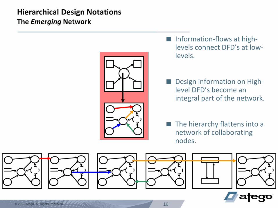
Hierarchical Design Notations The Emerging Network
Information-flows at high-levels connect DFD’s at low-levels.
Design information on High-level DFD’s become an integral part of the network.
The hierarchy flattens into a network of collaborating nodes.
17 © 2011 Atego. All Rights Reserved.
Resulting Modelling Language considerations
Hierarchical design notations are deficient in detailing the distributed
nature of IMS modules.
Limited (if any) extensibility to capture specific IMS properties.
A notation capable to handle networks of generic elements is needed
=> UML (and SysML)!
18 © 2011 Atego. All Rights Reserved. © 2011 Atego. All Rights Reserved.
UML/SysML Modelling for IMS Using standards and their extensibility
19 © 2011 Atego. All Rights Reserved.
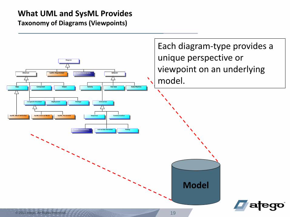
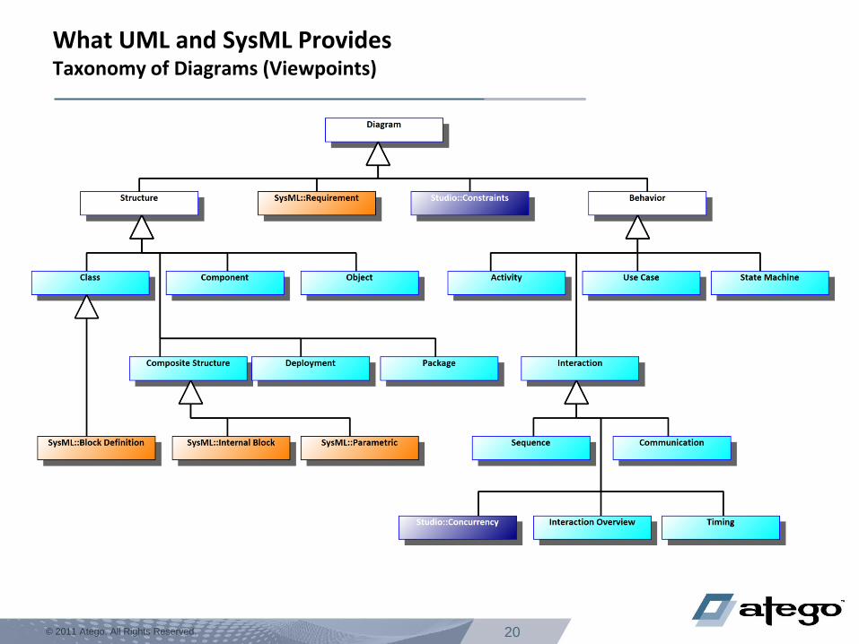
What UML and SysML Provides Taxonomy of Diagrams (Viewpoints)
Model
A model contains artefacts and interrelationships between artefacts.
Each diagram-type provides a unique perspective or viewpoint on an underlying model.
20 © 2011 Atego. All Rights Reserved.
What UML and SysML Provides Taxonomy of Diagrams (Viewpoints)
21 © 2011 Atego. All Rights Reserved.
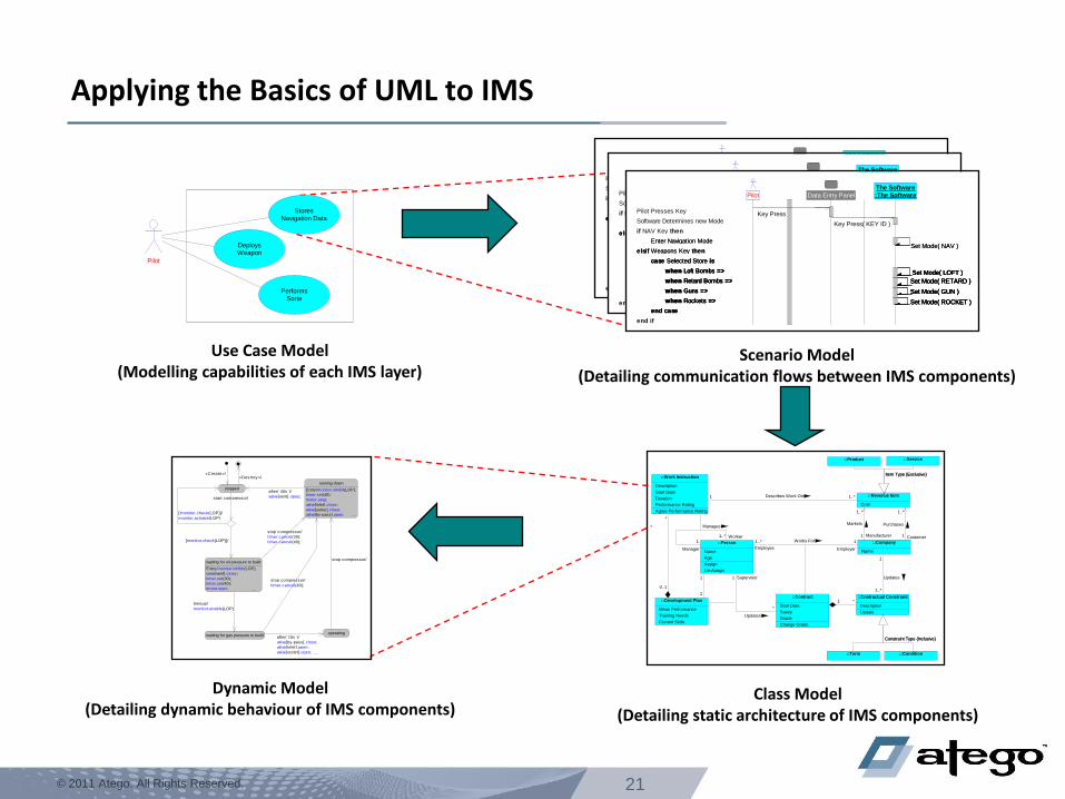
Applying the Basics of UML to IMS
Pilot
StoresNavigation Data
DeploysWeapon
PerformsSorte
Use Case Model (Modelling capabilities of each IMS layer)
The Software
:The SoftwarePilot Data Entry Panel
Pilot Presses KeyKey Press
Software Determines new ModeKey Press( KEY ID )
if NAV Key then
Enter Navigation ModeSet Mode( NAV )
elsif Weapons Key then
case Selected Store is
when Loft Bombs => Set Mode( LOFT )
when Retard Bombs => Set Mode( RETARD )
when Guns => Set Mode( GUN )
when Rockets => Set Mode( ROCKET )
end case
end if
Enter Navigation ModeSet Mode( NAV )
elsif Weapons Key then
case Selected Store is
when Loft Bombs => Set Mode( LOFT )
when Retard Bombs => Set Mode( RETARD )
when Guns => Set Mode( GUN )
when Rockets => Set Mode( ROCKET )
end case
case Selected Store is
when Loft Bombs => Set Mode( LOFT )
when Retard Bombs => Set Mode( RETARD )
when Guns => Set Mode( GUN )
when Rockets => Set Mode( ROCKET )
end case
when Loft Bombs => Set Mode( LOFT )
when Retard Bombs => Set Mode( RETARD )
when Guns => Set Mode( GUN )
when Rockets => Set Mode( ROCKET )
Scenario Model (Detailing communication flows between IMS components)
::Person
Name
Age
Assign
Un-Assign
::Company
Name
::Contract
Start Date
Salary
Grade
Change Grade
::Work Instruction
Description
Start Date
Duration
Performance Rating
Agree Performance Rating
::Revenue Item
Cost
::Product ::Service
::Development Plan
Mean Performance
Training Needs
Current Skills
::Contractual Constraint
Description
Update
::Term ::Condition
11..* Works For
Employee Employer
1..*
1
Manages
Manager
Worker
1..*
1
Markets
Manufacturer
1..*1 Describes Work On
*
0..1
1
1
*
1
Updates
Supervisor
*1
1..*
1
Updates
1..*
1
Purchases
Customer
Item Type {Exclusive}Item Type {Exclusive}
Constraint Type {Inclusive}Constraint Type {Inclusive}
Class Model (Detailing static architecture of IMS components)
running down
Entry/monitor.inhibit(LOP);
timer.set(40);
motor.stop;
valve[inlet].close;
valve[outlet].close;
valve[by-pass].open; ...
stopped
waiting for oil pressure to build
Entry/monitor.inhibit(LOP);
valve[vent].close;
timer.set(30);
timer.set(40);
motor.start; ...
waiting for gas pressure to buildoperating
timeup/
monitor.enable(LOP)
start compressor/
after( 40s )/
valve[vent].open;...
after( 10s )/
valve[by-pass].close;
valve[inlet].open;
valve[outlet].open; ...
stop compressor/
«Destroy»/
stop compressor/
timer.cancel(30);
timer.cancel(40);
stop compressor/
timer.cancel(40);
«Create»/
[!monitor.check(LOP)]/
monitor.activate(LOP)
[monitor.check(LOP)]/
Dynamic Model (Detailing dynamic behaviour of IMS components)
23 © 2011 Atego. All Rights Reserved.
Extending the SysML & UML Notation
SysML & UML can be extended by «Stereotypes»
Stereotypes are applied to standard UML model-elements.
Additional properties (“Tags Definitions”) are added to stereotypes.
SysML & UML can encompass any language domain:
Software Engineering − Programming Languages (e.g. Ada, Java, C, C++, C#, IDL, VB) − Real-time Systems (OMG MARTE Profile) − Component-based Development − Incremental Development
Systems Engineering − IMS Terminology (Stanag 4626/EN 4660 & ARINC-653) − Business Terminology − System On Chip (OMG SoC Profile) − Architecture Analysis & Design Language (SAE AADL Profile) − Goal Structured Notation (GSN) − Architectural Frameworks
– Zachman – UPDM (MODAF/DoDAF)
− AUTOSAR − …
24 © 2011 Atego. All Rights Reserved.
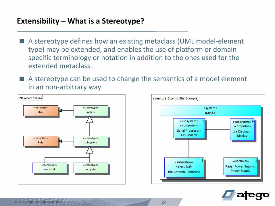
Extensibility – What is a Stereotype?
A stereotype defines how an existing metaclass (UML model-element type) may be extended, and enables the use of platform or domain specific terminology or notation in addition to the ones used for the extended metaclass.
A stereotype can be used to change the semantics of a model element in an non-arbitrary way.
25 © 2011 Atego. All Rights Reserved.
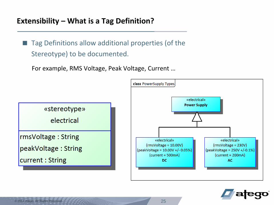
Extensibility – What is a Tag Definition?
Tag Definitions allow additional properties (of the
Stereotype) to be documented.
For example, RMS Voltage, Peak Voltage, Current …
26 © 2011 Atego. All Rights Reserved.
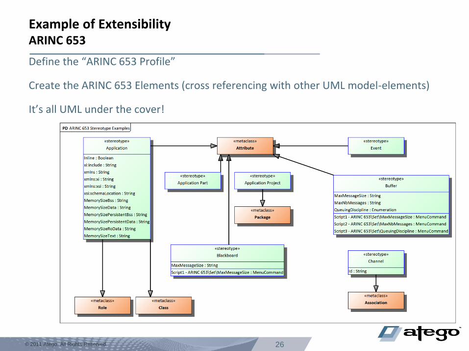
Example of Extensibility ARINC 653
Define the “ARINC 653 Profile”
Create the ARINC 653 Elements (cross referencing with other UML model-elements)
It’s all UML under the cover!
27 © 2011 Atego. All Rights Reserved.
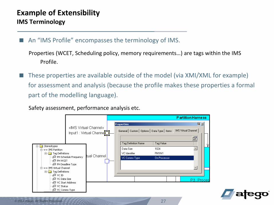
Example of Extensibility IMS Terminology
An “IMS Profile” encompasses the terminology of IMS.
Properties (WCET, Scheduling policy, memory requirements…) are tags within the IMS
Profile.
These properties are available outside of the model (via XMI/XML for example)
for assessment and analysis (because the profile makes these properties a formal
part of the modelling language).
Safety assessment, performance analysis etc.
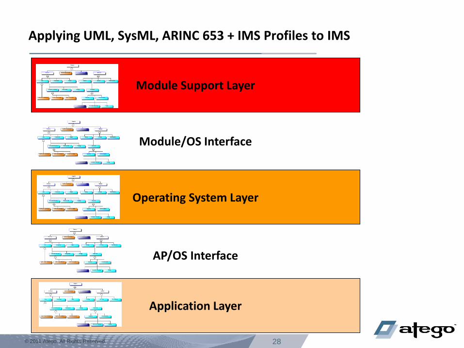
28 © 2011 Atego. All Rights Reserved.
Applying UML, SysML, ARINC 653 + IMS Profiles to IMS
Module Support Layer
Operating System Layer
Application Layer
Module/OS Interface
AP/OS Interface
29 © 2011 Atego. All Rights Reserved.
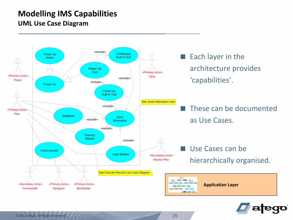
Pilot
«Primary Actor»
Mission Plan
«Secondary Actor»
Commander
«Secondary Actor»
Navigator
«Primary Actor»
Bombadier
«Primary Actor»
Time
«Primary Actor»
Power
«Primary Actor»
Power UpCold
StoreInformation
Load Mission
ContinuousBuilt-In Test
Communicate
ExecuteMission
Power UpBuilt-In Test
Power UpWarm
Power Up
Shutdown
«include»
«include»
«include»
«include»
«include»
«include»
«include»
See Execute Mission Use Case Diagram
See Store Information Use Case Diagram
Modelling IMS Capabilities UML Use Case Diagram
Each layer in the
architecture provides
‘capabilities’.
These can be documented
as Use Cases.
Use Cases can be
hierarchically organised.
Application Layer
30 © 2011 Atego. All Rights Reserved.
Land Aircraft
Description
Format Manager
:Formats::Format Manager
«Singleton»«Controller»
ILS Manager
:ILS::ILS Manager
«Singleton»«Controller» TheVORILS
:Logical::VOR ILS
«Singleton»
VOR/ILS
«Single Press Button»
Head Up (Front)
«Display Surface»
Head Up (Rear)
«Display Surface» VOR ILSNavigator
VOR ILS
«Equipment»NavigatorPilot
The Pilot informs the Navigator
to initiate a landing sequence
Initiate ILS Landing Sequence
The Navigator selects ILSSelect ILS
The VOR ILS (Subsystem) receives
the request to enter ILS.Toggle VORILS Mode
The VOR ILS (Subsystem) informs the
VOR ILS (Equipment) to enter ILS
mode.
Enter ILS
while ILS Not Active loop
Retrieve the State of the VOR ILS
(Equipment)Get State
end loop
VOR ILS informs the Format Manager
to Display the ILS FormatActivate Format( ILS Format )
Activate the Head Up (Front)
(Display)
with the ILS Format
Activate( ILS Format )
Activate the Head Up (Rear) (Display)
with the ILS FormatActivate( ILS Format )
Activate the ILS Manager Activate
while ILS Active loop
Schedule the ILS Manager Schedule
Retrieve the Raw Localiser DataRaw Localiser
Retrieve the Raw Glideslope DataRaw Glideslope
Retrieve the calculated Localiser
positionGet Localiser Sym Position
Retrieve the calculated Glideslope
positionGet Glideslope Sym Position
Update the Head Up (Front)
(Display)Update( ILS Symbology )
Update the Head Up (Rear)
(Display)Update( ILS Symbology )
end loop
Timeout Required?
Land Aircraft (System Only) Land Aircraft (Software Only)...
Exploring Use Case UML Interaction Diagrams
Hazard Analysis: What if something goes wrong?
Here
Or Here
Or Here
Or Here
Or Here
Or Here
31 © 2011 Atego. All Rights Reserved.
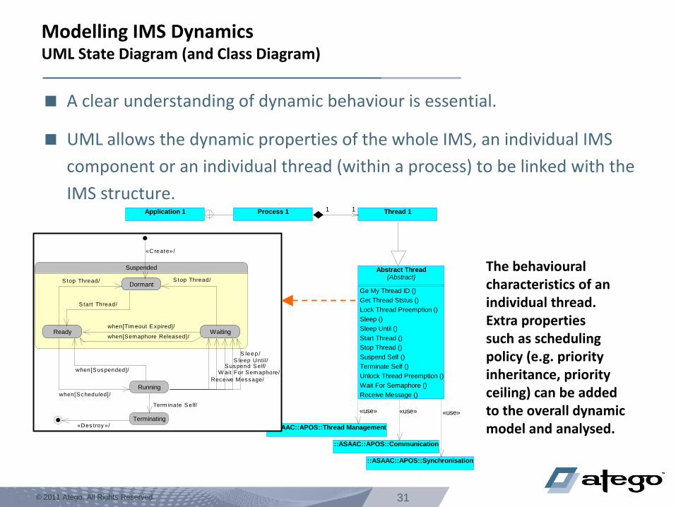
Modelling IMS Dynamics UML State Diagram (and Class Diagram)
A clear understanding of dynamic behaviour is essential.
UML allows the dynamic properties of the whole IMS, an individual IMS
component or an individual thread (within a process) to be linked with the
IMS structure. Thread 1
::ASAAC::APOS::Thread Management
Process 1Application 1
Abstract Thread{Abstract}
Ge My Thread ID ()
Get Thread Ststus ()
Lock Thread Preemption ()
Sleep ()
Sleep Until ()
Start Thread ()
Stop Thread ()
Suspend Self ()
Terminate Self ()
Unlock Thread Preemption ()
Wait For Semaphore ()
Receive Message ()
::ASAAC::APOS::Communication
::ASAAC::APOS::Synchronisation
11
«use» «use» «use»
Running
Ready
Dormant
Waiting
Suspended
Ready
Dormant
Waiting
Terminating
«C reate»/
S tart Thread/
S top Thread/ S top Thread/
when[Sc heduled]/
when[S us pended]/
S leep /
Term inate Self/
S leep Until/
when[Timeout E xpired]/
«Des troy »/
S uspend Self/
when[Semaphore Released]/
W ait For Semaphore/
Receive Message/
The behavioural characteristics of an individual thread. Extra properties such as scheduling policy (e.g. priority inheritance, priority ceiling) can be added to the overall dynamic model and analysed.
32 © 2011 Atego. All Rights Reserved.
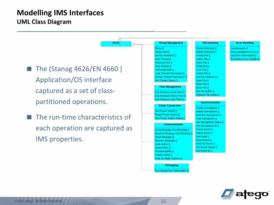
Modelling IMS Interfaces UML Class Diagram
The (Stanag 4626/EN 4660 )
Application/OS interface
captured as a set of class-
partitioned operations.
The run-time characteristics of
each operation are captured as
IMS properties.
APOS Thread Management
Sleep ()
Sleep Until ()
Ge My Thread ID ()
Start Thread ()
Suspend Self ()
Stop Thread ()
Terminate Self ()
Lock Thread Preemption ()
Unlock Thread Preemption ()
Get Thread Ststus ()
Time Management
Get Absolute Local Time ()
Get Absolute Global Time ()
Get Relative Local Time ()
Synchronisation
Create Semaphore ()
Delete Semaphore ()
Wait For Semaphore ()
Post Semaphore ()
Get Semaphore Status ()
Get Semaphore ID ()
Create Event ()
Delete Event ()
Set Event ()
Reset Event ()
Wait For Event ()
Get Event Status ()
Get Event ID ()
Error Handling
Log Message ()
Raise Application Error ()
Get Error Information ()
Terminate Error Handler ()
Debugging
Get Debug Error Information ()
Communication
Send Message Non Blocking ()
Receive Message Non Blocking ()
Send Message ()
Receive Message ()
Lock Buffer ()
Send Buffer ()
Receive Buffer ()
Unlock Buffer ()
Wait On Multi Channel ()
File Handling
Create Directory ()
Delete Directory ()
Create File ()
Delete File ()
Open File ()
Close File ()
Lock File ()
Unlock File ()
Get File Attributes ()
Seek File ()
Read File ()
Write File ()
Get File Buffer ()
Release File Buffer ()
Power Conversion
Set Power Switch ()
Reset Power Switch ()
Get Power Switch Status ()
33 © 2011 Atego. All Rights Reserved.
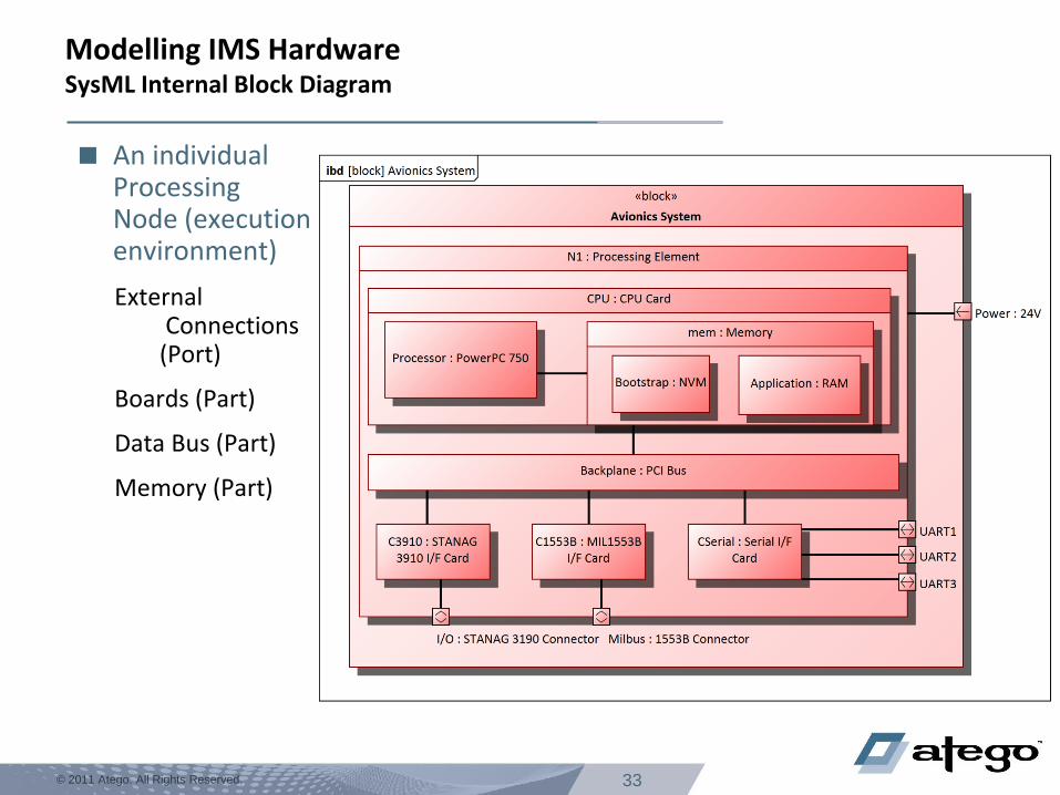
Modelling IMS Hardware SysML Internal Block Diagram
An individual Processing Node (execution environment)
External Connections (Port)
Boards (Part)
Data Bus (Part)
Memory (Part)
34 © 2011 Atego. All Rights Reserved.
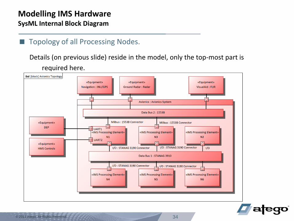
Modelling IMS Hardware SysML Internal Block Diagram
Topology of all Processing Nodes.
Details (on previous slide) reside in the model, only the top-most part is
required here.
38 © 2011 Atego. All Rights Reserved. © 2011 Atego. All Rights Reserved.
Model-based Support of ARINC 653
39 © 2011 Atego. All Rights Reserved.
A Summary on ARINC653
Standard, supporting IMS
Aerospace and beyond
Strong partitioning between applications leads to:
System robustness
Reuse
Application in different configurations
Certification where Application changes context
Decreased recertification costs (improved change isolation)
Reduce cost of over-certifying lower SIL applications
Isolate them from higher SIL applications using partitioning
Reduce cost of re-certifying unchanged applications
Where applications in other partitions have changed
40 © 2011 Atego. All Rights Reserved.
ARINC 653 Support
Openly integrated with RTOS and IDE’s
Supporting ARINC 653
APEX
Applications make calls to the Application Executive defined by ARINC 653 to
decouple the applications from vendor ARINC 653 implementations
Primarily Text Entry
Application behavior and initialization is coded in programming languages (Ada, C,
etc)
System configuration is coded in XML files (ARINC 653 concepts such as partitions,
ports, channels etc)
41 © 2011 Atego. All Rights Reserved.
Benefits of using UML and ARINC 653 together
Synergistic advantages
Ease of Adoption
Clearer Workflow
Communication
Productivity
Link between configuration and applications clearer in single model
Possibility to automate and re-use model-based software engineering
techniques
42 © 2011 Atego. All Rights Reserved.
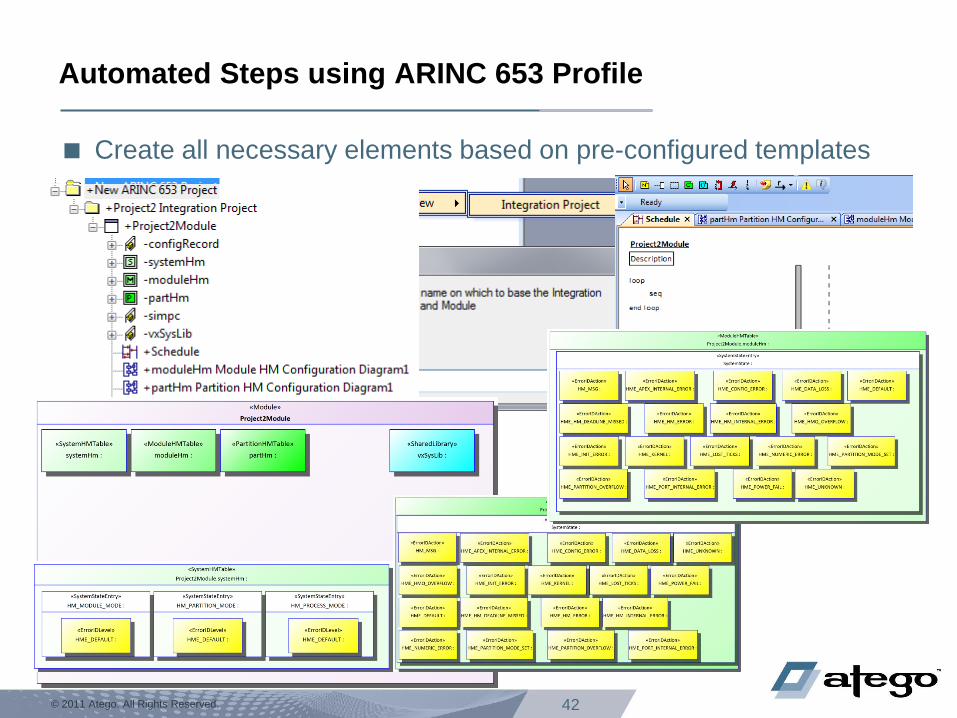
Automated Steps using ARINC 653 Profile
Create all necessary elements based on pre-configured templates
43 © 2011 Atego. All Rights Reserved.
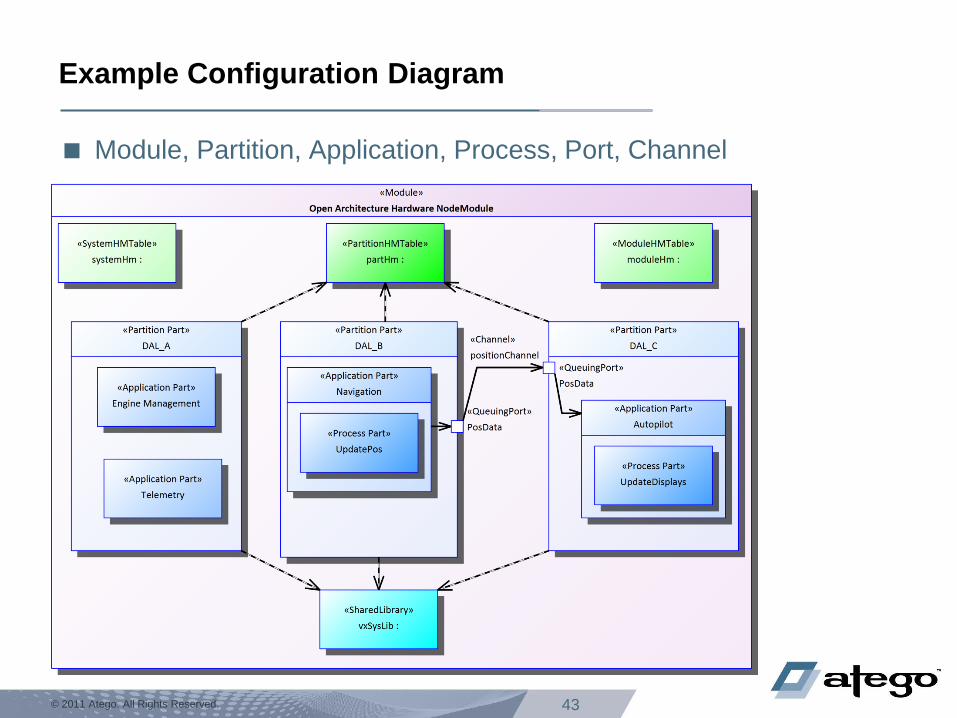
Example Configuration Diagram
Module, Partition, Application, Process, Port, Channel
44 © 2011 Atego. All Rights Reserved.
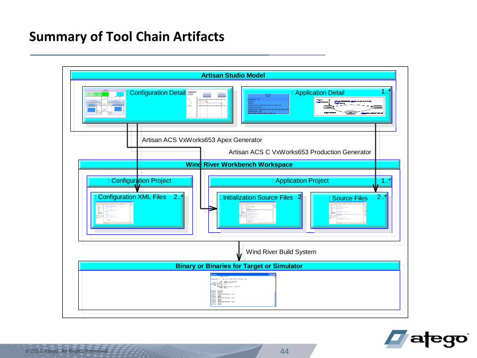
Artisan Studio Model
: Configuration Detail : Application Detail 1..*
Wind River Workbench Workspace
1..*: Application Project
: Source Files 2..* : Initialization Source Files 2
: Configuration Project
: Configuration XML Files 2..*
Binary or Binaries for Target or Simulator
Artisan ACS VxWorks653 Apex Generator
Artisan ACS C VxWorks653 Production Generator
Wind River Build System
«Process»
Player1
MsgReceived : char
entrypoint ()
Player1 ()
RxMsg (in PortID : QUEUING_PORT_ID_TYPE) : int
DisplayReceivedMsg ()
TxMsg (in PortID : QUEUING_PORT_ID_TYPE, inout Msg : char)
Print (inout Text : char)
After (in Time : SYSTEM_TIME_TYPE) : int
BallGameModule
Description
Player1Partition
«Partition Part»
Player2Partition
«Partition Part»
loop
seq
«ScheduleWindow» {ReleasePoint, DurationSeconds = 0.25}
seq
«ScheduleWindow» {ReleasePoint, DurationSeconds = 0.25}end loop
«Module»
BallGameModule
«SystemHMTable»
systemHm :
«ModuleHMTable»
moduleHm :
«PartitionHMTable»
partHm :
«SharedLibrary»
vxSysLib :
«Partition Part»
Player1Partition : Player1Partition
«Application Part»
Player1Application :Player1Application
«Process Part»
Player1 : Player1
«QueuingPort»
QueuingPort1
«QueuingPort»
QueuingPort2
«Partition Part»
Player2Partition : Player2Partition
«Application Part»
Player2Application : Player2Application
«Process Part»
Player2 : Player2
«QueuingPort»
QueuingPort1
«QueuingPort»
QueuingPort2«Channel»
Channel1
«Channel»
Channel2
BallGameModule
Description
Player1Partition
«Partition Part»
Player2Partition
«Partition Part»
loop
seq
«ScheduleWindow» {ReleasePoint, DurationSeconds = 0.25}
seq
«ScheduleWindow» {ReleasePoint, DurationSeconds = 0.25}end loop
«Module»
BallGameModule
«SystemHMTable»
systemHm :
«ModuleHMTable»
moduleHm :
«PartitionHMTable»
partHm :
«SharedLibrary»
vxSysLib :
«Partition Part»
Player1Partition : Player1Partition
«Application Part»
Player1Application :Player1Application
«Process Part»
Player1 : Player1
«QueuingPort»
QueuingPort1
«QueuingPort»
QueuingPort2
«Partition Part»
Player2Partition : Player2Partition
«Application Part»
Player2Application : Player2Application
«Process Part»
Player2 : Player2
«QueuingPort»
QueuingPort1
«QueuingPort»
QueuingPort2«Channel»
Channel1
«Channel»
Channel2
«Process»
Player1
MsgReceived : char
entrypoint ()
Player1 ()
RxMsg (in PortID : QUEUING_PORT_ID_TYPE) : int
DisplayReceivedMsg ()
TxMsg (in PortID : QUEUING_PORT_ID_TYPE, inout Msg : char)
Print (inout Text : char)
After (in Time : SYSTEM_TIME_TYPE) : int
Summary of Tool Chain Artifacts
46 © 2011 Atego. All Rights Reserved.
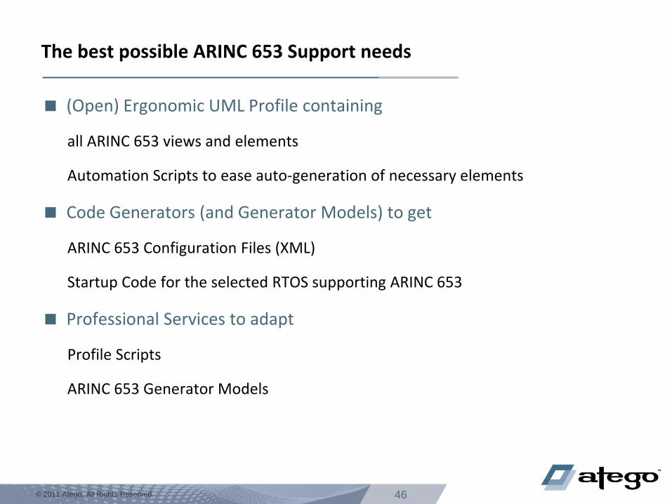
The best possible ARINC 653 Support needs
(Open) Ergonomic UML Profile containing
all ARINC 653 views and elements
Automation Scripts to ease auto-generation of necessary elements
Code Generators (and Generator Models) to get
ARINC 653 Configuration Files (XML)
Startup Code for the selected RTOS supporting ARINC 653
Professional Services to adapt
Profile Scripts
ARINC 653 Generator Models
48 © 2011 Atego. All Rights Reserved.
Questions and Answers
DescriptionDescription You
:Attendee
Me
:Speaker
loop1
You
:Attendee
Me
:Speaker
loop1 while open questions exist
Question1.1
end loop
while open questions exist
Question1.1Question
Answer1.1.1Question
Answer1.1.1AnswerAnswer
end loop
{Speech Time}{Speech Time}
![Software Model Checking of ARINC-653 Flight Code with … · Software Model Checking of ARINC-653 Flight Code with MCP ... [13]; it consists of ... rather than on a mod el that has](https://static.fdocuments.us/doc/165x107/5b1ca3e57f8b9aef288b51bc/software-model-checking-of-arinc-653-flight-code-with-software-model-checking.jpg)


![Blinder: Partition-Oblivious Hierarchical Scheduling › system › files › sec21summer_yoon.pdfof ARINC 653 standard [8] and MILS systems employ this table-driven approach as the](https://static.fdocuments.us/doc/165x107/60b717e16d94d36f9c53b64a/blinder-partition-oblivious-hierarchical-scheduling-a-system-a-files-a-sec21summeryoonpdf.jpg)