Sleep and Rest Nursing Fundamental NURS B20 Nursing Fundamental NURS B20.

Model B20/63
Combined Chlorine
Recorder Home Office European Office Analytical Technology, Inc. ATI (UK) Limited 6 Iron Bridge Drive Unit 1 & 2 Gatehead Business Park Collegeville, PA 19426 Delph New Road, Delph Saddleworth OL3 5DE Ph: (800) 959-0299 Ph: 0800-018-4020 (610) 917-0991 + 44 (0) 1457-873-318 Fax: (610) 917-0992 Fax: + 44 (0) 1457-874-468

Model B20/63 Combined Chlorine Recorder
O & M Manual Revision C, 5/02 - 2 -
Email: [email protected] Email: [email protected]
PRODUCT WARRANTY Analytical Technology, Inc. (Manufacturer) warrants to the Customer that if any part(s) of the Manufacturer's products proves to be defective in materials or workmanship within the earlier of 18 months of the date of shipment or 12 months of the date of start-up, such defective parts will be repaired or replaced free of charge. Inspection and repairs to products thought to be defective within the warranty period will be completed at the Manufacturer's facilities in Oaks, PA. Products on which warranty repairs are required shall be shipped freight prepaid to the Manufacturer. The product(s) will be returned freight prepaid and allowed if it is determined by the manufacturer that the part(s) failed due to defective materials or workmanship. This warranty does not cover consumable items, batteries, or wear items subject to periodic replacement including lamps and fuses. Gas sensors, except oxygen sensors, are covered by this warranty, but are subject to inspection for evidence of extended exposure to excessive gas concentrations. Should inspection indicate that sensors have been expended rather than failed prematurely, the warranty shall not apply. The Manufacturer assumes no liability for consequential damages of any kind, and the buyer by acceptance of this equipment will assume all liability for the consequences of its use or misuse by the Customer, his employees, or others. A defect within the meaning of this warranty is any part of any piece of a Manufacturer's product which shall, when such part is capable of being renewed, repaired, or replaced, operate to condemn such piece of equipment. This warranty is in lieu of all other warranties (including without limiting the generality of the foregoing warranties of merchantability and fitness for a particular purpose), guarantees, obligations or liabilities expressed or implied by the Manufacturer or its representatives and by statute or rule of law. This warranty is void if the Manufacturer's product(s) has been subject to misuse or abuse, or has not been operated or stored in accordance with instructions or if the serial number has been removed. Analytical Technology, Inc. makes no other warranty expressed or implied except as stated above.
Model B20/63 Combined Chlorine Recorder
O & M Manual Revision C, 5/02 - 3 -
TABLE OF CONTENTS TABLE OF CONTENTS..................................................................................................................................... 3
UNPACKING....................................................................................................................................................... 4
INTRODUCTION................................................................................................................................................ 5
Figure 1 - Chlorine Monitoring System with Internal Transmitter (ATI-0131) ................................................ 6 Figure 2 - Chlorine Monitoring System with External Transmitter (ATI-0132)................................................ 6
SPECIFICATIONS.............................................................................................................................................. 7
RECORDER UNIT ............................................................................................................................................ 7 SENSOR............................................................................................................................................................ 7 FLOWCELL ASSEMBLY ................................................................................................................................. 7
INSTALLATION................................................................................................................................................. 8
Figure 3 - Recorder Installation (ATI-0107)................................................................................................... 8 Figure 4 - Flowcell Dimensions (ATI-042)...................................................................................................... 9 Figure 5 - Sensor Pipe Mount Installation (ATI-0155).................................................................................. 10 Figure 6 - Mounting Assembly Detail (ATI-0188)........................................................................................ 11
ELECTRICAL CONNECTIONS...................................................................................................................... 12
Figure 7 - Recorder Customer Connections with Internal Transmitter (ATI-0134)........................................ 12 Figure 8- Recorder Customer Connections with Remote Transmitter (ATI-0135).......................................... 13 Figure 9 - Junction Box Dimensions (ATI-068)............................................................................................. 14 Figure 10 - Junction Box Interconnect Wiring (ATI-0137)............................................................................ 15
CHLORINE SENSOR ASSEMBLY ................................................................................................................. 16
Figure 11 - Chlorine Flow Sensor Assembly (ATI-0246)............................................................................... 17 Figure 12 - Chlorine Submersible Sensor Assembly (ATI-0245).................................................................... 17
START-UP ......................................................................................................................................................... 18
CHART SPEED SELECTION.................................................................................................................................. 18 CHART PAPER INSTALLATION ............................................................................................................................ 18 PEN INSTALLATION ........................................................................................................................................... 18 SETTING CHART TIME ....................................................................................................................................... 18 PROGRAMMING UNITS WITH DIGITAL DISPLAY OPTION....................................................................................... 19
Figure 13 - Recorder Front with Potentiometers, etc. (ATI-0136)................................................................ 19 Figure 14 - Transmitter Test Points (ATI-085)............................................................................................. 20
OPERATION ..................................................................................................................................................... 21
ZEROING THE SYSTEM................................................................................................................................ 21 FLOW SYSTEM STARTUP ............................................................................................................................ 22 CALIBRATION............................................................................................................................................... 23
MAINTENANCE............................................................................................................................................... 24
SENSOR MAINTENANCE ............................................................................................................................. 24 FLOWCELL MAINTENANCE........................................................................................................................ 25
SPARE PARTS LIST......................................................................................................................................... 26

Model B20/63 Combined Chlorine Recorder
O & M Manual Revision C, 5/02 - 4 -
UNPACKING When you receive your B20 Chlorine Recorder, open the shipping package and inspect the contents to be sure that all items have been received. The following items should be included: Quantity 1 - Model B20 Recorder Quantity 1 - Model A10-63 Chlorine Sensor Quantity 1 - #03-0029 25 ft. sensor interconnect cable (if flow type probe is supplied) Quantity 1 - #00-0043 Clear Flowcell Assembly (if supplied with flow sensor) Quantity 1 - #09-0010 4 Oz. Bottle of Combined Chlorine Electrolyte Quantity 1 - #05-0007 Box of 10 Combined Chlorine Membranes Quantity 1 - #05-0004 Spare Parts Kit, containing O-rings and screws (flow sensor only) Quantity 1 - #05-0010 Spare Parts Kit, containing 0-rings and screws (submersible sensor only) Quantity 1 - AC Power Cord Quantity 1 - Model B12/63 Chlorine Transmitter (if remote transmitter option selected) In addition to the standard items listed above, any additional spare parts, junction boxes, cable, or spare sensors that were ordered separately will be included. Compare the contents of the shipping container with the packing list. The items listed above are the standard components that are included with every standard B20/63 combined chlorine recorder. Any other items will be listed separately on the packing list. Check the contents of the shipping container carefully to insure that nothing is overlooked. Should you find anything missing from the shipment, immediately contact the ATI sales department by calling either 800-959-0299 or 610-917-0991. If you prefer, you may send a fax describing the error to 610-917-0992.

Model B20/63 Combined Chlorine Recorder
O & M Manual Revision C, 5/02 - 5 -
INTRODUCTION The Model B20/63 is an on-line monitoring system designed for the continuous recording of combined chlorine in solution. The recorder is well suited for chloramine treated potable water systems and wastewater treatment effluent monitoring where the effluent is not nitrified. Units are available with operating ranges of 0-5 PPM or 0-20 PPM. For units with a range of 0-5 PPM, the recorder may be spanned for any operating ranges between 0-1 and 0-5 PPM. Units with an overall range of 0-20 PPM may be spanned for operating ranges between 0-5 and 0-20 PPM. The sensing system will operate on water streams with temperatures from 0 to 55° C. The basic sensing element used in the combined chlorine recorder is a polarographic membraned sensor which measures chlorine directly. Water simply flows past the sensor and directly to drain, with the flowrate and pressure across the sensor controlled by a constant head flow cell assembly. The chlorine measurement does not alter the sample or add any chemicals to the sample stream, so the water flow can return to the system if desired. When application conditions are suitable, the combined chlorine sensor may also be used submerged directly in the sample to be measured, such as an effluent channel. The main requirement for submerged use is that the sample flow always be greater than 0.3 FPS. Very stagnant sample flows will result in low measurements. The measured chlorine concentration is indicated directly on a 10" circular chart, which may be programmed for 8 hour, 12 hour, 24 hour, 48 hour or 7 day rotation. A 4–digit, red LED display is standard giveing a direct digital display of chlorine concentration in addition to the recording. A single 24 hour chart paper is supplied with the basic unit and additional paper can be obtained from ATI for either 24 hour or 7 day rotation speeds. All charts are graduated with a 0-100 % scale. Recorders employ replaceable felt tip pens for recording chlorine data. The recorder is supplied with one red pen as standard. Additional pens in packages of 6 are available from ATI (see parts list). The standard model B20/63 system includes three main components, a wall or panel mounted recorder unit, a constant head flow cell (for flow applications only), and a combined chlorine sensor. For connection of the sensor to the electronics, a 25' cable is supplied. The sensor cable may be extended up to 100 feet by use of a junction box (00-0048) and 5 conductor shielded sensor cable (31-0001) available from ATI. Should an application require location of the sensor more than 100 feet from the recorder, the chlorine amplifier may be located remote from the recorder up to 5000 feet and interconnected with 2 conductor shielded cable (31-0008). If a submersible sensor has been specified on the order, no flow cell is supplied with the system. The submersible sensor is supplied with a standard 25 ft. cable potted into the head of the sensor. It can be used with the same cables, junction box, and remote amplifier listed above.

Model B20/63 Combined Chlorine Recorder
O & M Manual Revision C, 5/02 - 6 -
Figure 1 - Chlorine Monitoring System with Internal Transmitter (ATI-0131)
Figure 2 - Chlorine Monitoring System with External Transmitter (ATI-0132)

Model B20/63 Combined Chlorine Recorder
O & M Manual Revision C, 5/02 - 7 -
SPECIFICATIONS RECORDER UNIT Range: 0-5 or 0-20 PPM, Selected at ordering time. Accuracy: ± 0.05 PPM Repeatability: ± 0.02 PPM Linearity: 0.5% of F.S. Display: 4-digit, red, LED display. Temperature Compensation: Automatic from -2° to +52° C. Recorder Size: 10" Circular Chart Chart Speed: Selectable for 8,12,24 & 48 hour or 7 days per revolution. Operating Conditions: 0-55° C., 0-95% R.H. non-condensing. Power: 100 to 240 VAC ±10%,47/63 Hz. Enclosure: NEMA 3R Noryl, Acrylic window, wall or panel mount. Size: 14"W x 14"H x 3.8"D SENSOR Response Time: 90% in 60 seconds. Temperature Sensor: 100K thermistor Temperature Limits: -5° to +55° C. Connection: Watertight 6 pin plug Materials: Noryl and stainless steel FLOWCELL ASSEMBLY Type: Constant head overflow system Materials: Clear Cast Acrylic, stainless steel mounting plate Inlet Flow: 7-30 GPH, 15 GPH recommended. Inlet Connection: 1/4" Hose barb Drain Connection: 1/2" Hose barb Size: 4.5"W x 7"H x 3.5"D
Model B20/63 Combined Chlorine Recorder
O & M Manual Revision C, 5/02 - 8 -
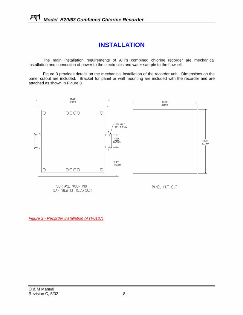
INSTALLATION The main installation requirements of ATI's combined chlorine recorder are mechanical installation and connection of power to the electronics and water sample to the flowcell. Figure 3 provides details on the mechanical installation of the recorder unit. Dimensions on the panel cutout are included. Bracket for panel or wall mounting are included with the recorder and are attached as shown in Figure 3.
Figure 3 - Recorder Installation (ATI-0107)

Model B20/63 Combined Chlorine Recorder
O & M Manual Revision C, 5/02 - 9 -
Combined chlorine sensors are best used in a constant head overflow chamber because variations in sample flow rate and pressure can cause unstable readings. When monitoring low concentrations (below 0.5 PPM), this method should always be used. Some applications, however, are much easier done using a submersible sensor. This method can sometimes be used where flow is reasonably constant, and adequate flow is always present. Chlorine sensors can never be used in completely stagnant conditions. A flow velocity of at least 0.3 feet per second is normally required for measurement. Any applications for a submersible chlorine sensor should first be discussed with ATI. A trial of such installations may be necessary. Mechanical installation of the flowcell requires that it be mounted to a wall or other convenient flat surface. Alternatively, the mounting holes on the plate will accommodate a 2" U-bolt for mounting the plate to a 2" pipe. Figure 4 shows the dimensions and mounting hole locations for the flowcell. Be sure to allow enough clearance on the left side of the flowcell for insertion and removal of the sensor. About 12 inches clearance is recommended.
4.50"114mm2.75"70mm
6.40"163mm
7.0"178mm
CUSTOMER MOUNTING HOLES(4) 1/4-20 THRU HOLES 14 GA ALUMINUM
CLEAR ACRYLIC
1/4" INLET1/2" DRAIN
3.50"89mm
Figure 4 - Flowcell Dimensions (ATI-042) Once mounted, inlet and drain connections must be made. The flowcell contains a 1/8" MNPT inlet connection and a 3/8" MNPT drain connection. Hose barbs for the inlet and drain connections are supplied with the flowcell for use with flexible tubing. The inlet hose barb is used with 1/4" I.D. tubing and the drain hose barb is used with 1/2" I.D. tubing.

Model B20/63 Combined Chlorine Recorder
O & M Manual Revision C, 5/02 - 10 -
Submersible sensors are mounted to a 1" pipe using a standard 1" PVC thread by thread pipe coupling. The mounting pipe can be secured to standard 1 1/2" pipe rail using a mounting bracket kit available from ATI (part number 00-0628) as shown in Figures 5 and 6.
Figure 5 - Sensor Pipe Mount Installation (ATI-0155)

Model B20/63 Combined Chlorine Recorder
O & M Manual Revision C, 5/02 - 11 -
Figure 6 - Mounting Assembly Detail (ATI-0188)

Model B20/63 Combined Chlorine Recorder
O & M Manual Revision C, 5/02 - 12 -
ELECTRICAL CONNECTIONS All electrical connections are made inside the recorder unit. Refer to Figure 7 below for the proper connections. A power cord is supplied with each unit for AC connection and a 5 conductor shielded interconnect cable is supplied for connection of the chlorine sensor to the recorder. Refer to Figure 8 for interconnection of a system with remote chlorine amplifier.
Figure 7 - Recorder Customer Connections with Internal Transmitter (ATI-0134)

Model B20/63 Combined Chlorine Recorder
O & M Manual Revision C, 5/02 - 13 -
Figure 8- Recorder Customer Connections with Remote Transmitter (ATI-0135)

Model B20/63 Combined Chlorine Recorder
O & M Manual Revision C, 5/02 - 14 -
For installations where the sensor is to be located more than 25 feet from the recorder (max. 100 feet), a junction box must be used. The junction box is shown in Figure 9 and is supplied with a 1/2" conduit hub on one end and a sensor cable gland on the other end.
Figure 9 - Junction Box Dimensions (ATI-068)

Model B20/63 Combined Chlorine Recorder
O & M Manual Revision C, 5/02 - 15 -
Installation wiring for systems containing a junction box is shown in Figure 10.
Figure 10 - Junction Box Interconnect Wiring (ATI-0137)

Model B20/63 Combined Chlorine Recorder
O & M Manual Revision C, 5/02 - 16 -
CHLORINE SENSOR ASSEMBLY
The chlorine sensor supplied with the B20 is shipped dry. It will not operate until it is prepared by adding electrolyte and a membrane. Preparation of the sensor for operation must be done carefully. The procedure should be done by a qualified technician, and it should only be done when the system is ready for operation. Until then, it is best to leave the sensor in the condition in which it is received. Refer to Figures 11 and 12 on the following page. Follow the procedure below to prepare the chlorine sensor for operations: 1. Unscrew the electrolyte canister from the assembled sensor and also remove the vent screw from
the side of the sensor body. 2. Remove the membrane cap from the bottom of the canister and discard the protective membrane.
O-rings are contained in grooves on both the bottom and top of the canister. Be sure that these o-rings remain in place.
3. From the package of membranes supplied with the sensor, place a new membrane into the
membrane cap. The membrane is white in color and is separated from other membranes by a light blue paper spacer.
4. Screw the membrane cap on to the canister until you feel the o-ring compress. Hand tight
compression is all that is needed. Do not use tools to tighten. The membrane should be flat across the bottom of the canister without wrinkles.
5. Fill the canister with electrolyte until the level reaches the bottom of the internal threads. 6. Slowly screw the canister onto the sensor body. A small amount of electrolyte will run out of the hole
from which the vent screw was removed. Place a paper towel around the sensor to absorb the electrolyte overflow. The electrolyte is harmless and will not irritate skin. Tighten the canister until the o-ring at the top of the canister is compressed. Once again, do not use tools to tighten.
7. Shake excess electrolyte from the vent hole on the side of the sensor and replace the vent screw. The sensor is now ready for operation. The membrane should be stretched tightly across the tip of the sensor. When handling the assembled sensor, do not set the sensor on its tip or damage to the membrane will result. Severe impacts on the tip of the sensor from dropping or other misuse may cause permanent damage to the sensor.

Model B20/63 Combined Chlorine Recorder
O & M Manual Revision C, 5/02 - 17 -
Figure 11 - Chlorine Flow Sensor Assembly (ATI-0246)
Figure 12 - Chlorine Submersible Sensor Assembly (ATI-0245)

Model B20/63 Combined Chlorine Recorder
O & M Manual Revision C, 5/02 - 18 -
START-UP Prior to operation, recheck electrical connections to be sure that everything is in accordance with customer connection diagrams. If everything is in order, power may be applied to the recorder. Note that AC power connection is made to a terminal block TB1. Position 1 for “hot”, position 2 for neutral and position 3 for ground. The fuse is contained in a floating connector and attached to a power supply board. After power has been turned on, the unit must be allowed to stabilize for at least 3 hours prior to calibration. This time period is primarily to allow the sensor time to come to a stable zero. Stabilization will occur whether the sensor is in unchlorinated water or installed in the sensor with chlorinated water running through the flowcell. The simplest method is the place the sensor in the flowcell and allow normal sample to flow for 3 hours while the sensor stabilizes. Do not be concerned with the values being shown on the recorder or the display during this time. Chart Speed Selection All B20 chlorine recorders are factory set for 24 hour chart speed. However, the speed can be easily changed to different hour or 7 day rotation by a simple adjustment. The chart speed is programmed from the keyboard. To change the chart speed, the selector switch, located to the left of the key pad, must be moved to the “program” mode. When the switch position is changed, “pro9” will appear on the display. Press the DOWN arrow once, then press the SCROLL key, press DOWN key once again and then the SCROLL key once again. The display will now indicate the current chart speed, normally 24 hours. To change speed, use the up or down arrow as required until the desired speed is indicated on the display. When speed selection is complete, simply slide the program switch back to the “run” position. Chart Paper Installation While the sensor is stabilizing, install a clean recorder chart in the unit. One chart is shipped with the instrument haveing a 24 hour scale. To make chart changing easier, the pen arm can be moved to the outside of the chart via the program set-up but typically can be changed with the pen arm anywhere on the chart. To position the pen arm to the papers parimeter, place the mode swich to “run”. Press the SCROLL membrane key and “CC” will appear on the display. Press the DOWN key and the pen arm will move to the upscale position Place a new chart over the center hub and carefully place the edges of the chart paper under the three guides along the outer rim of the paper. Rotate the paper until the alignment pin next to the drive hub aligns with the hole in the chart paper. Pen Installation Recorder pens snap onto the pen arm of the recorder. Make sure the pen arm lifter is pulled forward for installation. Place the nub of the pen into the V groove at the end of the pen arm and snap the retaining clip around the pen arm. Setting Chart Time To align the time graduations on the chart paper with the pen, a time index is located at the top outer rim of the chart plate (see Figure 13). Turn the outer rim of the chart hub using the chart guide pin. DO NOT TRY TO MANUALLY TURN THE LARGE CHART DRIVE HUB OR DAMAGE TO THE DRIVE MAY RESULT.

Model B20/63 Combined Chlorine Recorder
O & M Manual Revision C, 5/02 - 19 -
Programming Units with Digital Display Option Recorder purchased with the digital display option may require two functions to be set using the programming keys located to the right of the display (Figure 13). The two functions that are set from this keyboard are the chart speed and the scaling of the display. Both of these are factory set, but adjustment may be needed if the desired chart speed or recorder range are different that the factory settings. When shipped from ATI, the chart speed will be set for 24 hour rotation. The digital display scaling will be set for 0-3.00 PPM for low range units and 0-10.00 PPM for high range units. To change the chart speed, press the SET UP key once, then press the FUNC key once and use the UP or DOWN keys to select the desired chart speed. When you have selected the desired speed, press the DISP key once to return to the normal display. To change the digital display scaling, press the SET UP key three times and then press the FUNC key four times. The display will now indicate either 3.00 or 10.00 depending on the range of the recorder, and the second line of the display will indicate INP HI. Use the UP or DOWN key to set the digital display to the desired full scale value. Note that the rate at which the display changes can be speeded up by holding either the UP or DOWN key down and pressing the other key. Each time the opposite key is pressed, the adjusted digit moves one digit to the left. When the desired value has been set, press the DISP key once to return to the main display. Note: When programming these functions, the display will revert to the main display if a key is not
pressed for one minute.
Figure 13 - Recorder Front with Potentiometers, etc. (ATI-0136)

Model B20/63 Combined Chlorine Recorder
O & M Manual Revision C, 5/02 - 20 -
Figure 14 - Transmitter Test Points (ATI-085)

Model B20/63 Combined Chlorine Recorder
O & M Manual Revision C, 5/02 - 21 -
OPERATION Once the sensor has had sufficient time to stabilize, the zero and span of the system must be set. Establishing a stable zero is critical to the proper operation of the recorder and should always be done before setting the span. The zero and span potentiometers used for adjustment are located on the chart plate to the lower left of the chart (see Figure 13). If your system was supplied with a remote chlorine amplifier, the zero and span potentiometers will be located on the remote amplifier and you will need a DVM to read the test point voltage in order to calibrate the system. ZEROING THE SYSTEM To establish a stable system zero, proceed as follows. The steps below assume that the sensor has been prepared in accordance with the Chlorine Sensor Assembly section earlier in this manual. Note that the 2-3 hour waiting time in step 2 below is not required if the recorder has been running for 3 hours prior to zeroing. If the unit has been running, the sensor will normally return to a stable zero within 15 minutes. 1. Connect the sensor to the electronics by plugging the cable plug into the receptacle on the top of the
sensor. Submersible sensors will normally be permanently wired to the recorder. 2. Place about an inch of water in a small beaker or other convenient container and immerse the tip of
the sensor. The water used need not be distilled, but it must not contain residual chlorine. For submersible sensors, submerge the entire sensor in a bucket of unchlorinated water. Allow the sensor to sit undisturbed for at least 2-3 hours.
3. After checking to see that the chart time index is set properly, push the pen arm lifter down so that
the pen tip is making contact with the recorder paper. Turn the zero potentiometer until the pen is indicating 0.0 PPM chlorine. If your unit contains the optional digital display, adjust the zero potentiometer until the display reads 0.00.
If your system is supplied with the optional remote amplifier, connect a DVM to the test points
indicated in Figure 14. Adjust the zero potentiometer until the voltage on the DVM reads .040V.

Model B20/63 Combined Chlorine Recorder
O & M Manual Revision C, 5/02 - 22 -
FLOW SYSTEM STARTUP The free chlorine recorder should be calibrated while operating on a chlorinated sample stream. Place the system into operation as follows: 1. Place the previously zeroed sensor into the sensor chamber of the flowcell assembly. The sensor is
inserted into the side of the flowcell and is sealed in place with a double o-ring. The o-rings are lubricated at the factory to allow the sensor to slide smoothly into place. If insertion becomes difficult, use a small amount of silicon grease to lubricate the o-rings.
2. Turn on the inlet water flow to the flowcell and adjust the inlet flowrate so that water is overflowing
from the inlet chamber. The best performance will be obtained when some water is always overflowing. This maintains constant flow and pressure on the sensor at all times.
3. Allow the system to operate undisturbed for 30-60 minutes. Assuming the water contains free
chlorine, the recorder will be indicating positive values. If the chlorine residual in the system is stable, the value on the recorder will increase to some PPM value and remain at that level. At that point, calibration may be completed.

Model B20/63 Combined Chlorine Recorder
O & M Manual Revision C, 5/02 - 23 -
CALIBRATION Calibration of the Residual Chlorine Recorder must be done against a laboratory measurement on the same sample that the sensor is measuring. A sample should be collected from the inlet line feeding the flowcell and quickly analyzed for combined chlorine. When calibrating, it is best to have a reasonably high concentration of combined chlorine in the system. The higher the value, the smaller will be the calibration errors caused by errors in the laboratory analytical procedure. It is generally preferable to calibrate at values above 0.5 PPM to reduce calibration errors. If possible, the amperometric titration procedure for combined chlorine should be used as the reference method. Alternately, the DPD colorimetric method may be used provided that the sample containing combined chlorine. The chlorine recorder paper has a 0-100 scale, which is read as 0-100% of the calibrated chlorine range. The user must determine the full scale value required and adjust the calibration accordingly. For instance, if the operating range is to be 0-3 PPM, a value of 1.0 PPM would be 33% on the chart. If the range is to be 0-2 PPM, a value of 1.0 PPM would be 50% on the chart. Calibrate the recorder according to the following steps. 1. With the recorder indicating a stable chlorine value, collect a sample from the inlet line and
determine the combined chlorine concentration using an appropriate laboratory method. 2. Using the span potentiometer (see Figure 13), adjust the chart pen value (or the digital display on the
recorder, if installed) to the percentage of scale calculated from the % of Chart Reading equation below. If your unit is supplied with a remote transmitter, use the Test Point Voltage equation to calculate the proper voltage at the test points of the transmitter. The transmitter output is between .040V and .200 V, proportional to span at the test point.
% Chart Reading = 100 x (Combined Cl2 Value ÷ Full Scale Span)
Test Point Voltage = [ .160V x (Combined Cl2 Value ÷ Full Scale Span) ] + .040V EXAMPLE Your B20 recorder is to be spanned for a range of 0-2 PPM combined chlorine. The laboratory measurement show a free chlorine concentration of 1.20 PPM. Calculate the percentage as follows:
% Chart Reading = 100 X (1.20 ÷ 2.00) = 100 X .60 = 60%
Test Point Voltage = [ .160V x ( 1.20 ÷ 2.00) ] + .040V In this case, the span potentiometer would be used to set the chart value to 60% or the test point voltage on a remote amplifier to .136 VDC.

Model B20/63 Combined Chlorine Recorder
O & M Manual Revision C, 5/02 - 24 -
MAINTENANCE The B20/62 Combined Residual Chlorine Recorder will generally provide unattended operation over long periods of time. With proper care, the system should continue to provide measurements indefinitely. For reliable operation, maintenance on the system must be done on a regular schedule. Keep in mind that preventive maintenance on a regular schedule is much less troublesome than emergency maintenance that always seems to come at the wrong time. SENSOR MAINTENANCE Virtually all of the maintenance required for operation of the Chlorine Recorder is sensor related. The electronics are generally trouble free. They are burned in at the factory and will likely have a problem only if random component failure occurs. Sensor maintenance is required for accurate measurements. The primary requirement is simply to keep the sensor membrane clean. The membrane is a microporous polymer that is resistant to anything that will be encountered in water streams. However, deposits can form on the surface or in the pores of the membrane, and these deposits will reduce the sensitivity. Certain constituents in water, mainly iron and manganese, will form precipitates when the water is chlorinated. These precipitates can sometimes form a coating on the membrane. Because membranes are microporous, they can be relatively difficult to clean effectively. Immersing the tip of the sensor in 1N nitric acid solution will sometimes remove deposits that cause low sensitivity, but this is not always the case. The recommended practice is to simply replace the membrane when it becomes fouled. To change a membrane, follow the Sensor Assembly procedure on page 14 of this manual. Do not reuse the electrolyte from the sensor when changing a membrane. Always refill with fresh electrolyte. The electrolyte is stable and does not have a limited shelf life. Even if no buildup is apparent on the membrane, it should be changed on a regular schedule. The recommended membrane change interval is every 3 months. For high purity water applications, this can probably be extended if desired, but a more frequent changing interval is a small price to pay for avoiding membrane failure at the wrong time. While the sensor is disassembled for membrane changing, examine the condition of the o-rings on both ends of the electrolyte canister. If the o-rings show any signs of damage, replace them with new ones from the spare parts kit. It is good practice to change these o-rings once a year, regardless of their condition.

Model B20/63 Combined Chlorine Recorder
O & M Manual Revision C, 5/02 - 25 -
FLOWCELL MAINTENANCE The maintenance on the flowcell is simply to keep it clean. The flowcell is clear to assist operators in examining the condition of the sensor without interfering with operations. Deposits on the flowcell will make this more difficult. The flowcell may be cleaned by wiping or by washing with detergents or dilute acids. Do not try to clean with solvents as the acrylic may craze or crack. Change the o-ring in the flowcell yearly or if any damage is observed. If insertion of the sensor into the flowcell becomes difficult, use silicon grease to lubricate the o-rings that hold the sensor in place. Use only enough grease to provide surface lubrication. Excess grease could foul the sensor membrane.

Model B20/63 Combined Chlorine Recorder
O & M Manual Revision C, 5/02 - 26 -
SPARE PARTS LIST
MODEL B20/63 PART NO. DESCRIPTION 00-1095 Combined chlorine recorder with display (internal transmitter) 00-1096 Recorder with display (external transmitter) 00-0555 Remote combined chlorine transmitter 01-0058 Remote combined chlorine transmitter circuit board 01-0064 Internal combined chlorine transmitter circuit board 03-0029 Sensor interconnect cable, 25 ft. 00-0574 Residual chlorine sensor, flowcell type 02-0057 Sensing Element, flowcell sensor 00-0577 Residual chlorine sensor, submersible, with 25' cable 02-0021 Sensing Module, submersible sensor 02-0017 Sensing Element, submersion sensor 02-0058 Submersion sensor holder 45-0007 Electrolyte chamber 48-0001 Membrane holder, type 316 stainless steel 45-0010 Membrane holder, noryl 05-0007* Combined chlorine Membranes, pkg. of 10 05-0004* Sensor screw and o-ring kit (for flowcell sensor) 05-0010 Sensor screw and o-ring kit (for submersible sensor) 09-0010* Combined chlorine electrolyte, 4 oz (120 cc) 00-0043 Flowcell assembly with mounting plate 42-0014* Flowcell o-ring (each) 55-0035* Pens, (Pkg. 5) 55-0039* Charts, 2 sided 24hr/7day Note: Items marked with an asterisk (*) are recommended spare parts.