
Model 6676 ForeFront Xtreme Chassis Assembly User … · Model 6676 ForeFront Xtreme Chassis...
50
Model 6676 ForeFront Xtreme Chassis Assembly User Guide Sales Office: +1 (301) 975-1000 Technical Support: +1 (301) 975-1007 E-mail: [email protected] URL: www.patton.com Document Number: 120031U Rev. C Part Number: 07M6676 Revised: December 17, 2004
Transcript of Model 6676 ForeFront Xtreme Chassis Assembly User … · Model 6676 ForeFront Xtreme Chassis...
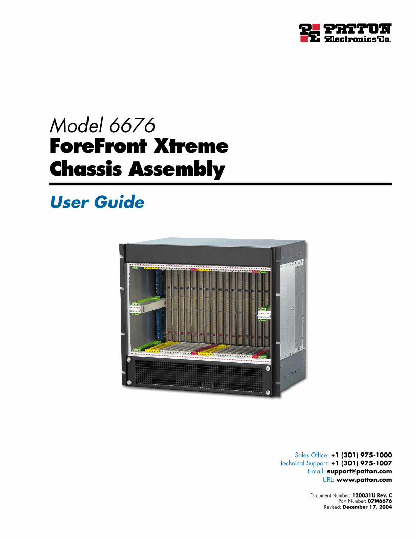
Model 6676
ForeFront Xtreme
Chassis Assembly
User Guide
Sales Office:
+1 (301) 975-1000
Technical Support:
+1 (301) 975-1007
E-mail:
URL:
www.patton.com
Document Number:
120031U Rev. C
Part Number:
07M6676
Revised:
December 17, 2004

Patton Electronics Company, Inc.
7622 Rickenbacker DriveGaithersburg, MD 20879 USA
tel: +1 (301) 975-1000fax: +1 (301) 869-9293
support: +1 (301) 975-1007url: www.patton.com
e-mail: [email protected]
Copyright Statement
Copyright © 2003–2004, Patton Electronics Company. All rights reserved.
Trademark Statement
The terms
ForeFront
and
ForeFront Xtreme
are trademarks of Patton Electronics Com-pany.
CompactPCI
and
PICMG
are registered trademarks of the PCI Industrial Com-puter Manufacturers Group. All other trademarks presented in this document are theproperty of their respective owners.
Notices
The information contained in this document is not designed or intended for use ascritical components in human life-support systems, equipment used in hazardousenvironments, or nuclear control systems. Patton Electronics Company disclaims anyexpress or implied warranty of fitness for such uses.
The information in this document is subject to change without notice. Patton Elec-tronics assumes no liability for errors that may appear in this document.
Any software described in this document is furnished under license and may be usedor copied only in accordance with the terms of such license.
Contents
Contents ......................................................................................................................................................... 3Compliance Information ................................................................................................................................ 5
Radio and TV Interference ...............................................................................................................................5Industry Canada Notice ....................................................................................................................................5FCC Part 68 Compliance Statement .................................................................................................................5CE Notice .........................................................................................................................................................5
About this guide.....................................................................................................................................................7Audience................................................................................................................................................................. 7Structure................................................................................................................................................................. 7Precautions ............................................................................................................................................................. 8Style conventions used in this document................................................................................................................. 8Typographical conventions used in this document.................................................................................................. 9
General conventions .........................................................................................................................................9Mouse conventions ...........................................................................................................................................9
1 Introduction.................................................................................................................................................. 11Introduction ..........................................................................................................................................................13
Description of chassis front side ......................................................................................................................14Description of chassis rear side ........................................................................................................................16Electromagnetic compatibility (EMC) ............................................................................................................17Electrostatic discharge (ESD) protection .........................................................................................................18Hot-swap capability ........................................................................................................................................19
Major system components .....................................................................................................................................20ForeFront AIS blades ......................................................................................................................................20Mid-plane architecture ....................................................................................................................................21Power supply module ......................................................................................................................................22
Fan tray module ..............................................................................................................................................22System specifications .............................................................................................................................................23
6U chassis specifications ..................................................................................................................................23Power input and power supply specifications ..................................................................................................24Fan tray specifications .....................................................................................................................................24
2 Installation checklist ..................................................................................................................................... 256U quick set-up checklist.......................................................................................................................................27
Power cable installation ...................................................................................................................................28Installing the power cables .........................................................................................................................28Grounding the Model 6676 ......................................................................................................................29
3 Maintenance.................................................................................................................................................. 31Preventive Maintenance.........................................................................................................................................33
Cleaning the fan filter .....................................................................................................................................33
3
Contents
Model 6676 6U CPCI Chassis Assembly User Guide
Troubleshooting ....................................................................................................................................................33System won’t power up ...................................................................................................................................33
4 Contacting Patton for assistance ................................................................................................................... 35Introduction ..........................................................................................................................................................37Contact information..............................................................................................................................................37
Service ............................................................................................................................................................37Warranty Service and Returned Merchandise Authorizations (RMAs)...................................................................37
Warranty coverage ..........................................................................................................................................38Out-of-warranty service .............................................................................................................................38Returns for credit ......................................................................................................................................38Return for credit policy .............................................................................................................................38
RMA numbers ................................................................................................................................................38Shipping instructions ................................................................................................................................38
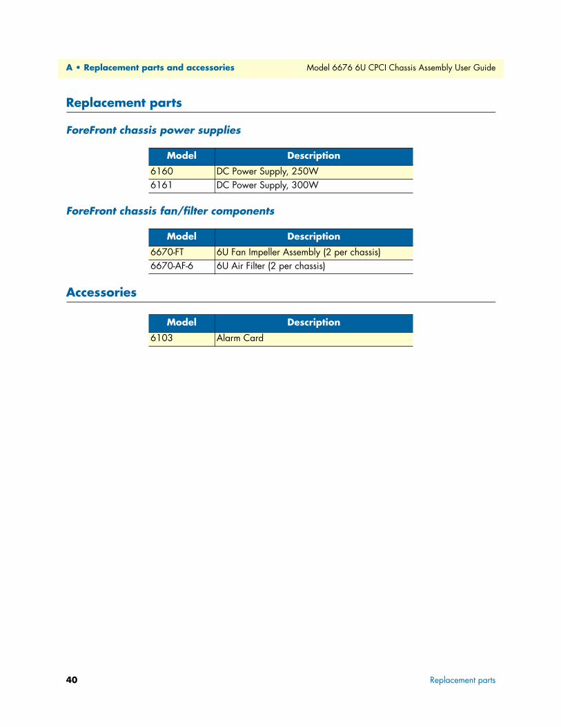
A Replacement parts and accessories ............................................................................................................... 39Replacement parts .................................................................................................................................................40
ForeFront chassis power supplies .....................................................................................................................40ForeFront chassis fan/filter components ..........................................................................................................40
Accessories.............................................................................................................................................................40
B Glossary ........................................................................................................................................................ 41C ...........................................................................................................................................................................43
CFM ...............................................................................................................................................................43CSA ................................................................................................................................................................43CT ..................................................................................................................................................................43
D...........................................................................................................................................................................43Dual Redundant .............................................................................................................................................43
E............................................................................................................................................................................43EIA .................................................................................................................................................................43EMC ...............................................................................................................................................................43
EMI ................................................................................................................................................................43EN ..................................................................................................................................................................43ESD ................................................................................................................................................................43
H...........................................................................................................................................................................43Hot-Swap .......................................................................................................................................................43HP ..................................................................................................................................................................43
I.............................................................................................................................................................................43IEC .................................................................................................................................................................43IEEE ...............................................................................................................................................................43
K ...........................................................................................................................................................................43Keying ............................................................................................................................................................43
N...........................................................................................................................................................................44N+1 Redundant ..............................................................................................................................................44NEBS .............................................................................................................................................................44
4
Model 6676 6U CPCI Chassis Assembly User Guide
Contents
P............................................................................................................................................................................44PCI .................................................................................................................................................................44PCI SIG ..........................................................................................................................................................44PICMG ..........................................................................................................................................................44Platform ..........................................................................................................................................................44
S ............................................................................................................................................................................44SELV ..............................................................................................................................................................44S-HAZ ............................................................................................................................................................44Shroud ............................................................................................................................................................44
T ...........................................................................................................................................................................44TDM ..............................................................................................................................................................44TNV ...............................................................................................................................................................44
U...........................................................................................................................................................................45U ....................................................................................................................................................................45
W ..........................................................................................................................................................................45Warm-Swap ....................................................................................................................................................45
C Bibliography ................................................................................................................................................. 47Publications referenced in this guide......................................................................................................................48
5

Contents
Model 6676 6U CPCI Chassis Assembly User Guide
6
Compliance Information
Radio and TV InterferenceThe Model 6676 ForeFront™ Xtreme™ Chassis generates and uses radio frequency energy, and if not installed and used properly—that is, in strict accordance with the manufacturer’s instructions—may cause interference to radio and television reception. The Model 6676 ForeFront Xtreme has been tested and found to comply with the limits for a Class A computing device in accordance with the specifications in Subpart B of Part 15 of FCC rules, which are designed to provide reasonable protection from such interference in a com-mercial installation. However, there is no guarantee that interference will not occur in a particular installation. If the Model 6676 ForeFront Xtreme Chassis causes interference to radio or television reception, which can be determined by disconnecting the cables, try to correct the interference by one or more of the following mea-sures: moving the computing equipment away from the receiver, re-orienting the receiving antenna, and/or plugging the receiving equipment into a different AC outlet (such that the computing equipment and receiver are on different branches).
Industry Canada Notice The Canadian Department of Communications label identifies certified equipment. This certification means that the equipment meets certain telecommunications network protective, operational and safety require-ments. The Department does not guarantee the equipment will operate to the user's satisfaction. Before install-ing this equipment, users should ensure that it is permissible to be connected to the facilities of the local telecommunications company. The equipment must also be installed using an acceptable method of connec-tion. In some cases, the company’s inside wiring associated with a single line individual service may be extended by means of a certified connector assembly (telephone extension cord). The customer should be aware that compliance with the above condition may not prevent degradation of service in some situations. Repairs to some certified equipment should be made by an authorized maintenance facility designated by the supplier. Any repairs or alterations made by the user to this equipment, or equipment malfunctions, may give the telecommunications company cause to request the user to disconnect the equipment. Users should ensure for their own protection that the ground connections of the power utility, telephone lines and internal metallic water pipe system, are connected together. This protection may be particularly important in rural areas.
FCC Part 68 Compliance StatementThis equipment complies with Part 68 of the FCC rules and the requirements adopted by the ACTA. Refer to the plug-in cards’ user guide for details.
CE NoticeThe CE symbol on your Patton Electronics equipment indicates that it is in compliance with the Electromag-netic Compatibility (EMC) directive and the Low Voltage Directive (LVD) of the European Union (EU). A Certificate of Compliance is available by contacting Technical Support.
Users should not attempt to establish or modify ground connections themselves, instead they should contact the appropriate electric inspection authority or electrician.
5

Model 6676 6U CPCI Chassis Assembly User Guide
6
About this guide
This manual is a comprehensive hardware reference tool for the Patton Electronics 6U cPCI Redundant Back-plane/Midplane and Chassis line of products.
AudienceThis guide is intended for the following users:
• System developers installing and integrating the products into their systems
• Operators
• Installers
• Maintenance technicians
StructureThis guide contains the following chapters and appendices:
• Chapter 1, "Introduction" on page 11 provides an overview of the product
• Chapter 2, "Installation checklist" on page 25 provides a quick set-up checklist for installing the Model 6676.
• Chapter 3, "Maintenance" on page 31 provides a quick set-up checklist, tips for troubleshooting, warranty information, and where to get help.
• Chapter 4, "Contacting Patton for assistance" on page 35 contains information on contacting Patton tech-nical support for assistance
• Appendix A, "Replacement parts and accessories" on page 39 provides model numbers and descriptions for replaceable components and accessories
• Appendix B, "Glossary" on page 41 defines terms and acronyms used in this document.
• Appendix C, "Bibliography" on page 47 provides a list publications used in conjunction with this manual
For best results, read the contents of this guide before you install the enclosure.
7
About this guide
Model 6676 6U CPCI Chassis Assembly User Guide
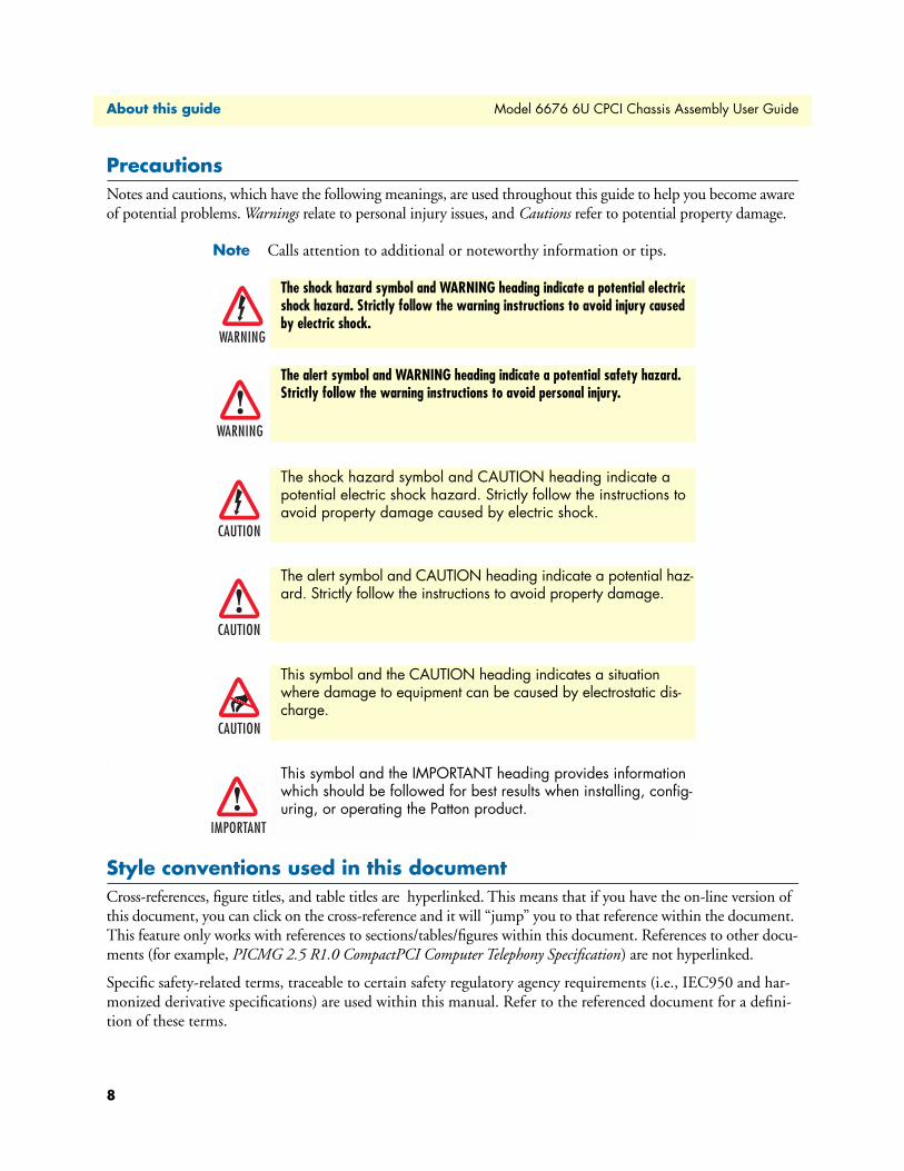
PrecautionsNotes and cautions, which have the following meanings, are used throughout this guide to help you become aware of potential problems. Warnings relate to personal injury issues, and Cautions refer to potential property damage.
Note Calls attention to additional or noteworthy information or tips.
.
Style conventions used in this documentCross-references, figure titles, and table titles are hyperlinked. This means that if you have the on-line version of this document, you can click on the cross-reference and it will “jump” you to that reference within the document. This feature only works with references to sections/tables/figures within this document. References to other docu-ments (for example, PICMG 2.5 R1.0 CompactPCI Computer Telephony Specification) are not hyperlinked.
Specific safety-related terms, traceable to certain safety regulatory agency requirements (i.e., IEC950 and har-monized derivative specifications) are used within this manual. Refer to the referenced document for a defini-tion of these terms.
The shock hazard symbol and WARNING heading indicate a potential electric shock hazard. Strictly follow the warning instructions to avoid injury caused by electric shock.
The alert symbol and WARNING heading indicate a potential safety hazard. Strictly follow the warning instructions to avoid personal injury.
The shock hazard symbol and CAUTION heading indicate a potential electric shock hazard. Strictly follow the instructions to avoid property damage caused by electric shock.
The alert symbol and CAUTION heading indicate a potential haz-ard. Strictly follow the instructions to avoid property damage.
This symbol and the CAUTION heading indicates a situation where damage to equipment can be caused by electrostatic dis-charge.
This symbol and the IMPORTANT heading provides information which should be followed for best results when installing, config-uring, or operating the Patton product.
8
Model 6676 6U CPCI Chassis Assembly User Guide
About this guide
Typographical conventions used in this documentThis section describes the typographical conventions and terms used in this guide.
General conventionsThe procedures described in this manual use the following text conventions:
Mouse conventionsThe following conventions are used when describing mouse actions:
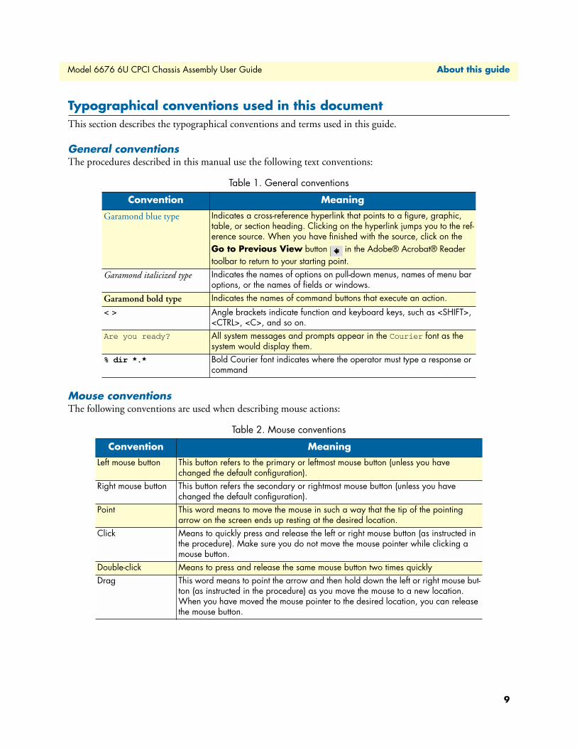
Table 1. General conventions
Convention Meaning
Garamond blue type Indicates a cross-reference hyperlink that points to a figure, graphic, table, or section heading. Clicking on the hyperlink jumps you to the ref-erence source. When you have finished with the source, click on the Go to Previous View button in the Adobe® Acrobat® Reader toolbar to return to your starting point.
Garamond italicized type Indicates the names of options on pull-down menus, names of menu bar options, or the names of fields or windows.
Garamond bold type Indicates the names of command buttons that execute an action.
< > Angle brackets indicate function and keyboard keys, such as <SHIFT>, <CTRL>, <C>, and so on.
Are you ready? All system messages and prompts appear in the Courier font as the system would display them.
% dir *.* Bold Courier font indicates where the operator must type a response or command
Table 2. Mouse conventions
Convention Meaning
Left mouse button This button refers to the primary or leftmost mouse button (unless you have changed the default configuration).
Right mouse button This button refers the secondary or rightmost mouse button (unless you have changed the default configuration).
Point This word means to move the mouse in such a way that the tip of the pointing arrow on the screen ends up resting at the desired location.
Click Means to quickly press and release the left or right mouse button (as instructed in the procedure). Make sure you do not move the mouse pointer while clicking a mouse button.
Double-click Means to press and release the same mouse button two times quicklyDrag This word means to point the arrow and then hold down the left or right mouse but-
ton (as instructed in the procedure) as you move the mouse to a new location. When you have moved the mouse pointer to the desired location, you can release the mouse button.
9

About this guide
Model 6676 6U CPCI Chassis Assembly User Guide
10
Chapter 1 Introduction
Chapter contentsIntroduction ..........................................................................................................................................................13
Description of chassis front side ......................................................................................................................14Description of chassis rear side ........................................................................................................................16Electromagnetic compatibility (EMC) ............................................................................................................17Electrostatic discharge (ESD) protection .........................................................................................................18Hot-swap capability ........................................................................................................................................19
Major system components .....................................................................................................................................20ForeFront AIS blades ......................................................................................................................................20Mid-plane architecture ....................................................................................................................................21Power supply module ......................................................................................................................................22Fan tray module ..............................................................................................................................................22
System specifications .............................................................................................................................................236U chassis specifications ..................................................................................................................................23Power input and power supply specifications ..................................................................................................24Fan tray specifications .....................................................................................................................................24
11

1 • Introduction
Model 6676 6U CPCI Chassis Assembly User Guide
12
Model 6676 6U CPCI Chassis Assembly User Guide
1 • Introduction
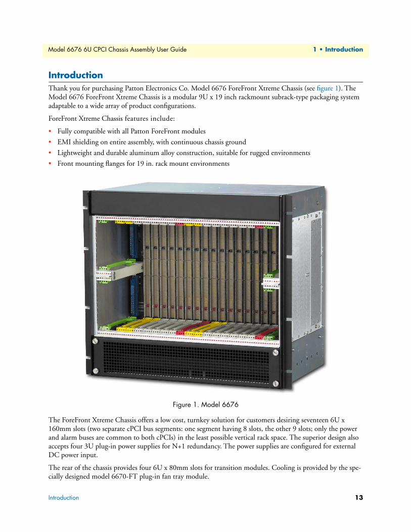
IntroductionThank you for purchasing Patton Electronics Co. Model 6676 ForeFront Xtreme Chassis (see figure 1). The Model 6676 ForeFront Xtreme Chassis is a modular 9U x 19 inch rackmount subrack-type packaging system adaptable to a wide array of product configurations.
ForeFront Xtreme Chassis features include:
• Fully compatible with all Patton ForeFront modules
• EMI shielding on entire assembly, with continuous chassis ground
• Lightweight and durable aluminum alloy construction, suitable for rugged environments
• Front mounting flanges for 19 in. rack mount environments
Figure 1. Model 6676
The ForeFront Xtreme Chassis offers a low cost, turnkey solution for customers desiring seventeen 6U x 160mm slots (two separate cPCI bus segments: one segment having 8 slots, the other 9 slots; only the power and alarm buses are common to both cPCIs) in the least possible vertical rack space. The superior design also accepts four 3U plug-in power supplies for N+1 redundancy. The power supplies are configured for external DC power input.
The rear of the chassis provides four 6U x 80mm slots for transition modules. Cooling is provided by the spe-cially designed model 6670-FT plug-in fan tray module.
Introduction 13
1 • Introduction
Model 6676 6U CPCI Chassis Assembly User Guide
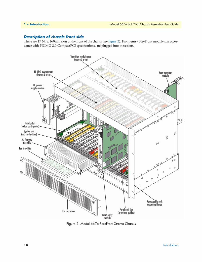
Description of chassis front sideThere are 17 6U x 160mm slots at the front of the chassis (see figure 2). Front-entry ForeFront modules, in accor-dance with PICMG 2.0 CompactPCI specifications, are plugged into these slots.
Figure 2. Model 6676 ForeFront Xtreme Chassis
14 Introduction
Model 6676 6U CPCI Chassis Assembly User Guide
1 • Introduction
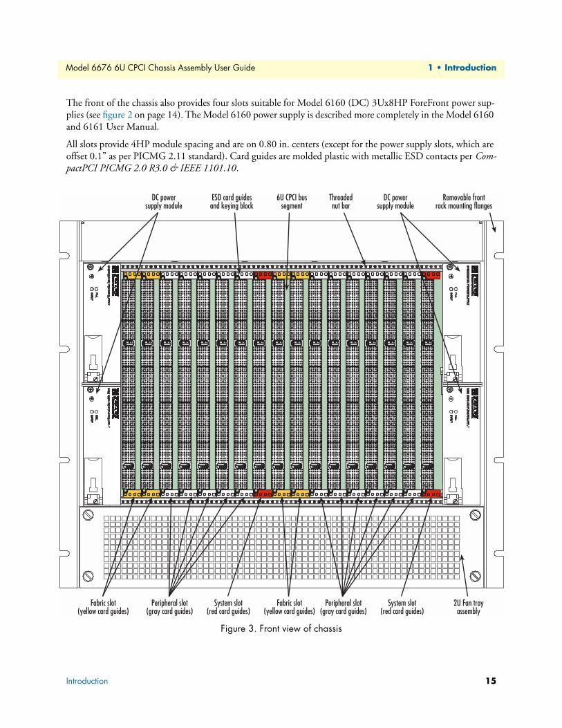
The front of the chassis also provides four slots suitable for Model 6160 (DC) 3Ux8HP ForeFront power sup-plies (see figure 2 on page 14). The Model 6160 power supply is described more completely in the Model 6160 and 6161 User Manual.
All slots provide 4HP module spacing and are on 0.80 in. centers (except for the power supply slots, which are offset 0.1” as per PICMG 2.11 standard). Card guides are molded plastic with metallic ESD contacts per Com-pactPCI PICMG 2.0 R3.0 & IEEE 1101.10.
Figure 3. Front view of chassis
Introduction 15
1 • Introduction
Model 6676 6U CPCI Chassis Assembly User Guide
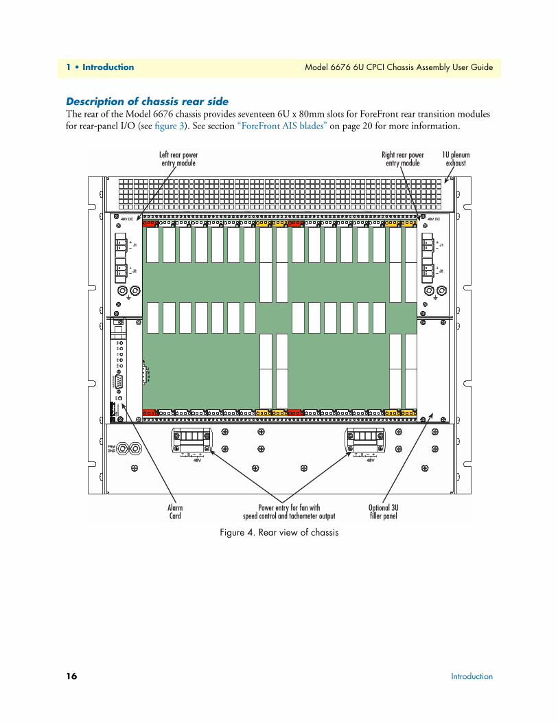
Description of chassis rear sideThe rear of the Model 6676 chassis provides seventeen 6U x 80mm slots for ForeFront rear transition modules for rear-panel I/O (see figure 3). See section “ForeFront AIS blades” on page 20 for more information.
Figure 4. Rear view of chassis
16 Introduction
Model 6676 6U CPCI Chassis Assembly User Guide 1 • Introduction
All slots provide 4HP module spacing and are on 0.80 in. centers. Card guides are molded plastic with metallic ESD contacts at the bottom of the chassis per CompactPCI PICMG 2.0 R3.0 & IEEE 1101.10. Cardguides provide keying and alignment in accordance with IEEE 1101.10, section 8.
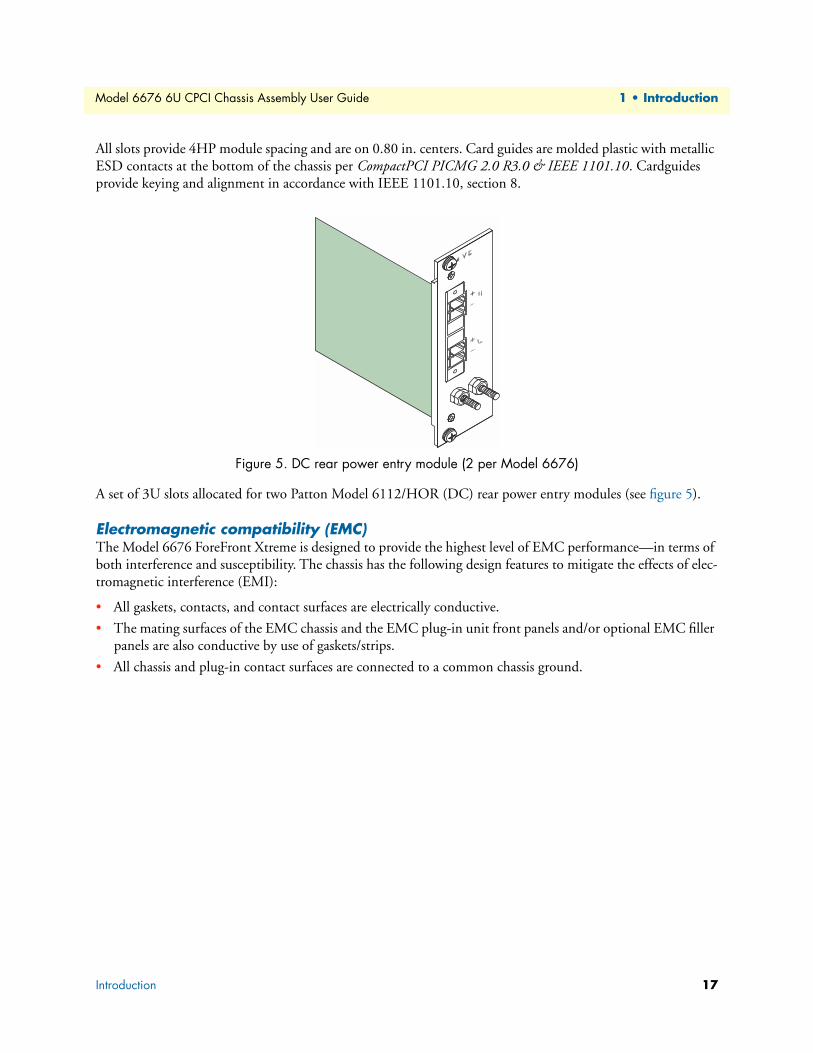
Figure 5. DC rear power entry module (2 per Model 6676)
A set of 3U slots allocated for two Patton Model 6112/HOR (DC) rear power entry modules (see figure 5).
Electromagnetic compatibility (EMC)The Model 6676 ForeFront Xtreme is designed to provide the highest level of EMC performance—in terms of both interference and susceptibility. The chassis has the following design features to mitigate the effects of elec-tromagnetic interference (EMI):
• All gaskets, contacts, and contact surfaces are electrically conductive.
• The mating surfaces of the EMC chassis and the EMC plug-in unit front panels and/or optional EMC filler panels are also conductive by use of gaskets/strips.
• All chassis and plug-in contact surfaces are connected to a common chassis ground.
Introduction 17
1 • Introduction Model 6676 6U CPCI Chassis Assembly User Guide
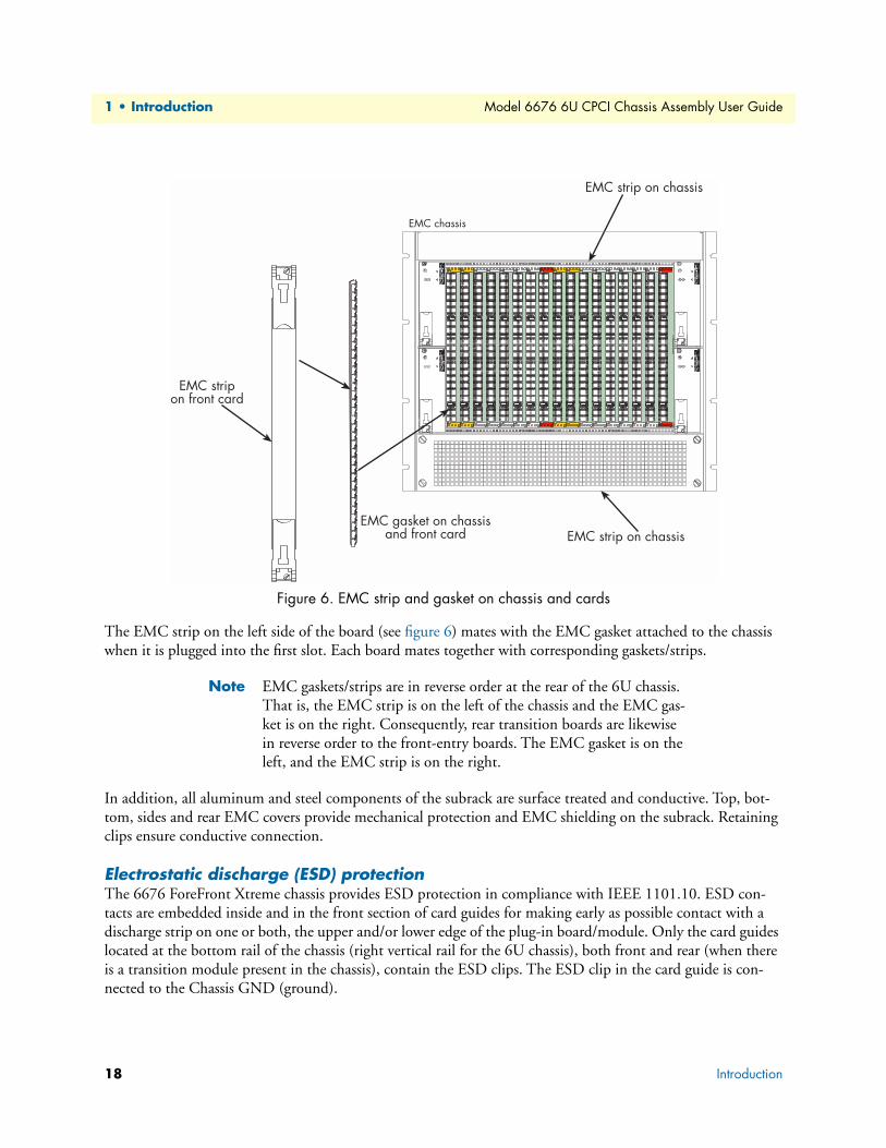
Figure 6. EMC strip and gasket on chassis and cards
The EMC strip on the left side of the board (see figure 6) mates with the EMC gasket attached to the chassis when it is plugged into the first slot. Each board mates together with corresponding gaskets/strips.
Note EMC gaskets/strips are in reverse order at the rear of the 6U chassis. That is, the EMC strip is on the left of the chassis and the EMC gas-ket is on the right. Consequently, rear transition boards are likewise in reverse order to the front-entry boards. The EMC gasket is on the left, and the EMC strip is on the right.
In addition, all aluminum and steel components of the subrack are surface treated and conductive. Top, bot-tom, sides and rear EMC covers provide mechanical protection and EMC shielding on the subrack. Retaining clips ensure conductive connection.
Electrostatic discharge (ESD) protectionThe 6676 ForeFront Xtreme chassis provides ESD protection in compliance with IEEE 1101.10. ESD con-tacts are embedded inside and in the front section of card guides for making early as possible contact with a discharge strip on one or both, the upper and/or lower edge of the plug-in board/module. Only the card guides located at the bottom rail of the chassis (right vertical rail for the 6U chassis), both front and rear (when there is a transition module present in the chassis), contain the ESD clips. The ESD clip in the card guide is con-nected to the Chassis GND (ground).
18 Introduction
Model 6676 6U CPCI Chassis Assembly User Guide 1 • Introduction
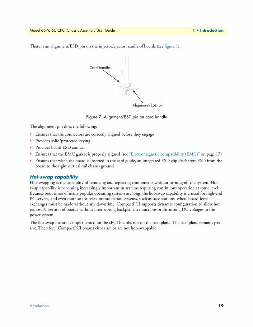
There is an alignment/ESD pin on the injector/ejector handle of boards (see figure 7).
Figure 7. Alignment/ESD pin on card handle
The alignment pin does the following:
• Ensures that the connectors are correctly aligned before they engage
• Provides solid/protected keying
• Provides board ESD contact
• Ensures that the EMC gasket is properly aligned (see “Electromagnetic compatibility (EMC)” on page 17)
• Ensures that when the board is inserted in the card guide, an integrated ESD clip discharges ESD from the board to the right vertical rail chassis ground.
Hot-swap capabilityHot-swapping is the capability of removing and replacing components without turning off the system. Hot-swap capability is becoming increasingly important in systems requiring continuous operation at some level. Because boot times of many popular operating systems are long, the hot-swap capability is crucial for high-end PC servers, and even more so for telecommunication systems, such as base stations, where board-level exchanges must be made without any downtime. CompactPCI supports dynamic configuration to allow hot removal/insertion of boards without interrupting backplane transactions or disturbing DC voltages in the power system.
The hot-swap feature is implemented on the cPCI boards, not on the backplane. The backplane remains pas-sive. Therefore, CompactPCI boards either are or are not hot-swappable.
Card handle
Alignment/ESD pin
Introduction 19
1 • Introduction Model 6676 6U CPCI Chassis Assembly User Guide
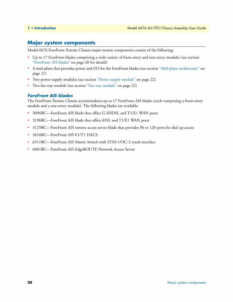
Major system componentsModel 6676 ForeFront Xtreme Chassis major system components consist of the following:
• Up to 17 ForeFront blades comprising a wide variety of front-entry and rear-entry modules (see section “ForeFront AIS blades” on page 20 for details)
• A mid-plane that provides power and I/O for the ForeFront blades (see section “Mid-plane architecture” on page 21)
• Two power supply modules (see section “Power supply module” on page 22)
• Two fan tray module (see section “Fan tray module” on page 22)
ForeFront AIS bladesThe ForeFront Xtreme Chassis accommodates up to 17 ForeFront AIS blades (each comprising a front-entry module and a rear-entry module). The following blades are available:
• 3096RC—ForeFront AIS blade that offers G.SHDSL and T1/E1 WAN ports
• 3196RC—ForeFront AIS blade that offers iDSL and T1/E1 WAN ports
• 3125RC—ForeFront AIS remote access server blade that provides 96 or 120 ports for dial-up access
• 2616RC—ForeFront AIS E1/T1 DACS
• 6511RC—ForeFront AIS Matrix Switch with STM-1/OC-3 trunk interface
• 6081RC—ForeFront AIS EdgeROUTE Network Access Server
20 Major system components
Model 6676 6U CPCI Chassis Assembly User Guide 1 • Introduction
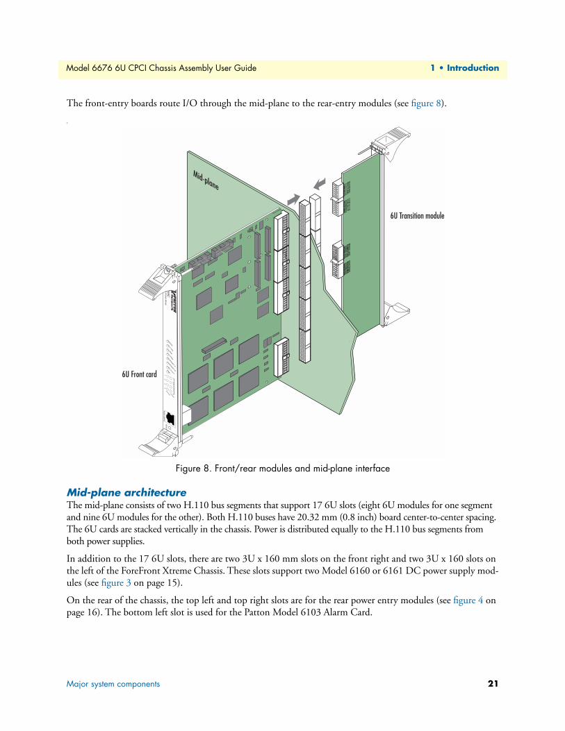
The front-entry boards route I/O through the mid-plane to the rear-entry modules (see figure 8).
T
Figure 8. Front/rear modules and mid-plane interface
Mid-plane architectureThe mid-plane consists of two H.110 bus segments that support 17 6U slots (eight 6U modules for one segment and nine 6U modules for the other). Both H.110 buses have 20.32 mm (0.8 inch) board center-to-center spacing. The 6U cards are stacked vertically in the chassis. Power is distributed equally to the H.110 bus segments from both power supplies.
In addition to the 17 6U slots, there are two 3U x 160 mm slots on the front right and two 3U x 160 slots on the left of the ForeFront Xtreme Chassis. These slots support two Model 6160 or 6161 DC power supply mod-ules (see figure 3 on page 15).
On the rear of the chassis, the top left and top right slots are for the rear power entry modules (see figure 4 on page 16). The bottom left slot is used for the Patton Model 6103 Alarm Card.
Major system components 21
1 • Introduction Model 6676 6U CPCI Chassis Assembly User Guide
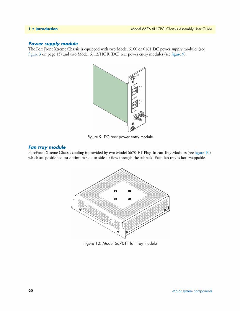
Power supply moduleThe ForeFront Xtreme Chassis is equipped with two Model 6160 or 6161 DC power supply modules (see figure 3 on page 15) and two Model 6112/HOR (DC) rear power entry modules (see figure 9).
Figure 9. DC rear power entry module
Fan tray moduleForeFront Xtreme Chassis cooling is provided by two Model 6670-FT Plug-In Fan Tray Modules (see figure 10) which are positioned for optimum side-to-side air flow through the subrack. Each fan tray is hot-swappable.
Figure 10. Model 6670-FT fan tray module
22 Major system components
Model 6676 6U CPCI Chassis Assembly User Guide 1 • Introduction
System specificationsThis section provides the following specifications:
• Model 6676 chassis specifications (see section “6U chassis specifications”)
• Power input and power supply specifications (see section “Power input and power supply specifications” on page 24)
• Fan tray specifications (see section “Fan tray specifications” on page 24)
6U chassis specifications
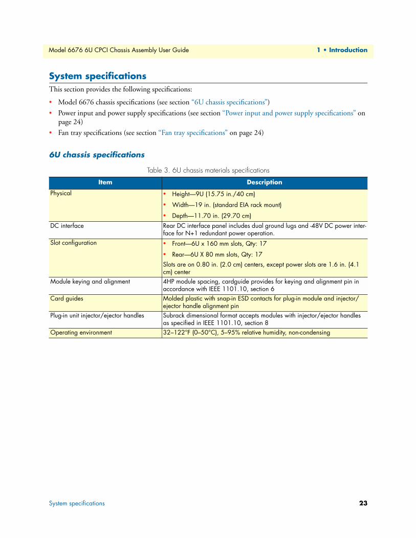
Table 3. 6U chassis materials specifications
Item Description
Physical • Height—9U (15.75 in./40 cm)
• Width—19 in. (standard EIA rack mount)
• Depth—11.70 in. (29.70 cm)
DC interface Rear DC interface panel includes dual ground lugs and -48V DC power inter-face for N+1 redundant power operation.
Slot configuration • Front—6U x 160 mm slots, Qty: 17
• Rear—6U X 80 mm slots, Qty: 17
Slots are on 0.80 in. (2.0 cm) centers, except power slots are 1.6 in. (4.1 cm) center
Module keying and alignment 4HP module spacing, cardguide provides for keying and alignment pin in accordance with IEEE 1101.10, section 6
Card guides Molded plastic with snap-in ESD contacts for plug-in module and injector/ejector handle alignment pin
Plug-in unit injector/ejector handles Subrack dimensional format accepts modules with injector/ejector handles as specified in IEEE 1101.10, section 8
Operating environment 32–122°F (0–50°C), 5–95% relative humidity, non-condensing
System specifications 23
1 • Introduction Model 6676 6U CPCI Chassis Assembly User Guide
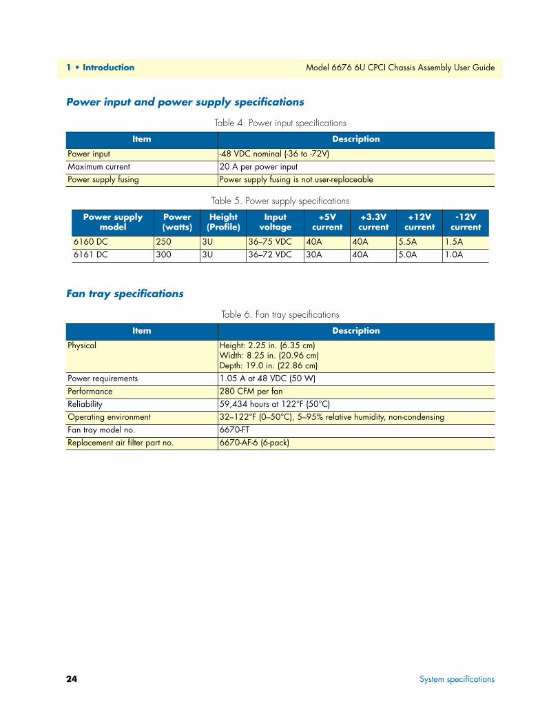
Power input and power supply specifications
Fan tray specifications
Table 4. Power input specifications
Item Description
Power input -48 VDC nominal (-36 to -72V)Maximum current 20 A per power inputPower supply fusing Power supply fusing is not user-replaceable
Table 5. Power supply specifications
Power supply model
Power(watts)
Height (Profile)
Input voltage
+5V current
+3.3V current
+12V current
-12V current
6160 DC 250 3U 36–75 VDC 40A 40A 5.5A 1.5A6161 DC 300 3U 36–72 VDC 30A 40A 5.0A 1.0A
Table 6. Fan tray specifications
Item Description
Physical Height: 2.25 in. (6.35 cm)Width: 8.25 in. (20.96 cm)Depth: 19.0 in. (22.86 cm)
Power requirements 1.05 A at 48 VDC (50 W)Performance 280 CFM per fanReliability 59,434 hours at 122°F (50°C)Operating environment 32–122°F (0–50°C), 5–95% relative humidity, non-condensingFan tray model no. 6670-FTReplacement air filter part no. 6670-AF-6 (6-pack)
24 System specifications
Chapter 2 Installation checklist
Chapter contents6U quick set-up checklist.......................................................................................................................................27
Power cable installation ...................................................................................................................................28Installing the power cables .........................................................................................................................28Grounding the Model 6676 ......................................................................................................................29
25

2 • Installation checklist Model 6676 6U CPCI Chassis Assembly User Guide
26
Model 6676 6U CPCI Chassis Assembly User Guide 2 • Installation checklist
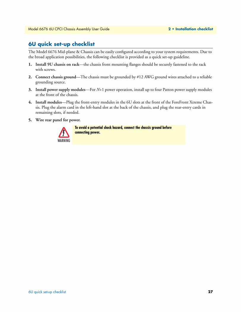
6U quick set-up checklistThe Model 6676 Mid-plane & Chassis can be easily configured according to your system requirements. Due to the broad application possibilities, the following checklist is provided as a quick set-up guideline.
1. Install 9U chassis on rack—the chassis front mounting flanges should be securely fastened to the rack with screws.
2. Connect chassis ground—The chassis must be grounded by #12 AWG ground wires attached to a reliable grounding source.
3. Install power supply modules—For N+1 power operation, install up to four Patton power supply modules at the front of the chassis.
4. Install modules—Plug the front-entry modules in the 6U slots at the front of the ForeFront Xtreme Chas-sis. Plug the alarm card in the left-hand slot at the back of the chassis, and plug the rear-entry cards in remaining slots, if needed.
5. Wire rear panel for power.
To avoid a potential shock hazard, connect the chassis ground before connecting power.
6U quick set-up checklist 27
2 • Installation checklist Model 6676 6U CPCI Chassis Assembly User Guide
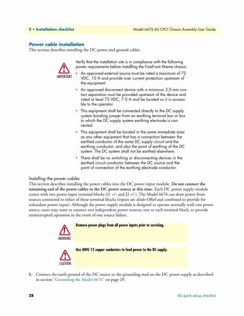
Power cable installationThis section describes installing the DC power and ground cables.
.
Installing the power cablesThis section describes installing the power cables into the DC power input module. Do not connect the remaining end of the power cables to the DC power source at this time. Each DC power supply module comes with two power input terminal blocks (J1 +/- and J2 +/-). The Model 6676 can draw power from sources connected to either of these terminal blocks (inputs are diode-ORed and combined to provide for redundant power input). Although the power supply module is designed to operate normally with one power source, users may want to connect two independent power sources, one to each terminal block, to provide uninterrupted operation in the event of one source failure.
1. Connect the earth ground of the DC source to the grounding stud on the DC power supply as described in section “Grounding the Model 6676” on page 29.
Verify that the installation site is in compliance with the following power requirements before installling the ForeFront Xtreme chassis:
• An approved external source must be rated a maximum of 72 VDC, 10 A and provide over current protection upstream of the equipment.
• An approved disconnect device with a minimum 3.0 mm con-tact separation must be provided upstream of the device and rated at least 75 VDC, 7.0 A and be located so it is accessi-ble to the operator.
• This equipment shall be connected directly to the DC supply system bonding jumper from an earthing terminal bar or bus to which the DC supply system earthing electrode is con-nected.
• This equipment shall be located in the same immediate area as any other equipment that has a connection between the earthed conductor of the same DC supply circuit and the earthing conductor, and also the point of earthing of the DC system. The DC system shall not be earthed elsewhere.
• There shall be no switching or disconnecting devices in the earthed circuit conductor between the DC source and the point of connection of the earthing electrode conductor.
Remove power plugs from all power inputs prior to servicing.
Use AWG 12 copper conductors to feed power to the DC supply.
28 6U quick set-up checklist
Model 6676 6U CPCI Chassis Assembly User Guide 2 • Installation checklist
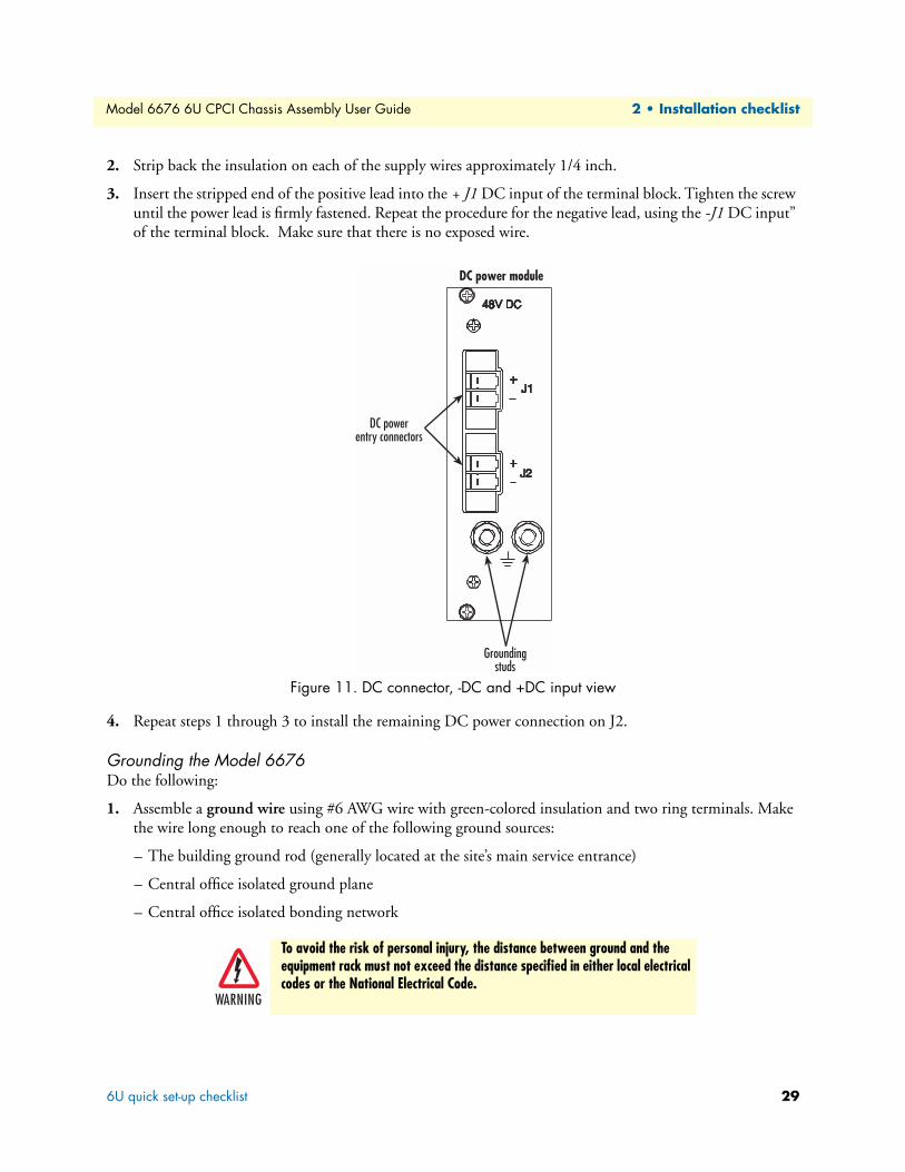
2. Strip back the insulation on each of the supply wires approximately 1/4 inch.
3. Insert the stripped end of the positive lead into the + J1 DC input of the terminal block. Tighten the screw until the power lead is firmly fastened. Repeat the procedure for the negative lead, using the -J1 DC input” of the terminal block. Make sure that there is no exposed wire.
Figure 11. DC connector, -DC and +DC input view
4. Repeat steps 1 through 3 to install the remaining DC power connection on J2.
Grounding the Model 6676Do the following:
1. Assemble a ground wire using #6 AWG wire with green-colored insulation and two ring terminals. Make the wire long enough to reach one of the following ground sources:
– The building ground rod (generally located at the site’s main service entrance)
– Central office isolated ground plane
– Central office isolated bonding network
To avoid the risk of personal injury, the distance between ground and the equipment rack must not exceed the distance specified in either local electrical codes or the National Electrical Code.
6U quick set-up checklist 29
2 • Installation checklist Model 6676 6U CPCI Chassis Assembly User Guide
2. Install the ground wire between the grounding studs (see figure 11 on page 29 for DC power entry) and the grounding source.
30 6U quick set-up checklist
Chapter 3 Maintenance
Chapter contentsPreventive Maintenance.........................................................................................................................................33
Cleaning the fan filter .....................................................................................................................................33Troubleshooting ....................................................................................................................................................33
System won’t power up ...................................................................................................................................33
31

3 • Maintenance Model 6676 6U CPCI Chassis Assembly User Guide
32
Model 6676 6U CPCI Chassis Assembly User Guide 3 • Maintenance
Preventive Maintenance
Cleaning the fan filterPeriodically clean the filter on the Fan Tray Assembly (see figure 2 on page 18). The frequency of cleaning depends on the environmental conditions of where your equipment is located. Clean filter with a mild deter-gent and water, then air-dry, or you can use compressed air. It should be completely dry before reuse.
Spare filters (part no. 6670-AF-6) are available from Patton Electronics Company.
Troubleshooting
System won’t power upIf the green LED on the power supply module does not light up, you should: remove the power supply module from the chassis, then plug it back in, making sure it is seated properly. If the green LED still does not illumi-nae, verify that the polarity is wired correctly at the back of the chassis.
If the green LED lights up on the power supply module, but the system still isn’t powering-up, then the mod-ule may be faulty and should be returned to the manufacturer.
Preventive Maintenance 33

3 • Maintenance Model 6676 6U CPCI Chassis Assembly User Guide
34 Troubleshooting
Chapter 4 Contacting Patton for assistance
Chapter contentsIntroduction ..........................................................................................................................................................37Contact information..............................................................................................................................................37
Service ............................................................................................................................................................37Warranty Service and Returned Merchandise Authorizations (RMAs)...................................................................37
Warranty coverage ..........................................................................................................................................38Out-of-warranty service .............................................................................................................................38Returns for credit ......................................................................................................................................38Return for credit policy .............................................................................................................................38
RMA numbers ................................................................................................................................................38Shipping instructions ................................................................................................................................38
35

4 • Contacting Patton for assistance Model 6676 6U CPCI Chassis Assembly User Guide
36
Model 6676 6U CPCI Chassis Assembly User Guide 4 • Contacting Patton for assistance
IntroductionThis chapter contains the following information:
• “Contact information”—describes how to contact Patton technical support for assistance.
• “Warranty Service and Returned Merchandise Authorizations (RMAs)”—contains information about the RAS warranty and obtaining a return merchandise authorization (RMA).
Contact informationPatton Electronics offers a wide array of free technical services. If you have questions about any of our other products we recommend you begin your search for answers by using our technical knowledge base. Here, we have gathered together many of the more commonly asked questions and compiled them into a searchable database to help you quickly solve your problems.
• Online support—available at www.patton.com.
• E-mail support—e-mail sent to [email protected] will be answered within 1 business day
• Telephone support—standard telephone support is available from 8AM to 5PM EST (8:00 to 17:00 UTC-5), Monday through Friday, by calling +1 (301) 975-1007
ServicePatton Electronics' technical staff is also available to answer any questions that might arise concerning the installation or use of your Model 6676. Technical Service hours: 8AM to 5PM EST (8:00 to 17:00 UTC-5), Monday through Friday.
All warranty and non-warranty repairs must be returned freight prepaid and insured to Patton Electronics (for more information about warranty and non-warranty repairs, see section “Warranty Service and Returned Mer-chandise Authorizations (RMAs)”). All returns must have a Return Materials Authorization number on the outside of the shipping container. This number may be obtained from Patton Electronics Technical Service at:
• Tel: (301) 975-1007
• E-mail: [email protected]
• URL: www.patton.com
Note Packages received without an RMA number will not be accepted.
Warranty Service and Returned Merchandise Authorizations (RMAs)Patton Electronics is an ISO-9001 certified manufacturer and our products are carefully tested before ship-ment. All of our products are backed by a comprehensive warranty program.
Note If you purchased your equipment from a Patton Electronics reseller, ask your reseller how you should proceed with warranty service. It is often more convenient for you to work with your local reseller to obtain a replacement. Patton services our products no matter how you acquired them.
Introduction 37
4 • Contacting Patton for assistance Model 6676 6U CPCI Chassis Assembly User Guide
Warranty coverageOur products are under warranty to be free from defects, and we will, at our option, repair or replace the prod-uct should it fail within one year from the first date of shipment. Our warranty is limited to defects in work-manship or materials, and does not cover customer damage, lightning or power surge damage, abuse, or unauthorized modification.
Out-of-warranty servicePatton services what we sell, no matter how you acquired it, including malfunctioning products that are no longer under warranty. Our products have a flat fee for repairs. Units damaged by lightning or other catastro-phes may require replacement.
Returns for creditCustomer satisfaction is important to us, therefore any product may be returned with authorization within 30 days from the shipment date for a full credit of the purchase price. If you have ordered the wrong equipment or you are dissatisfied in any way, please contact us to request an RMA number to accept your return. Patton is not responsible for equipment returned without a Return Authorization.
Return for credit policy • Less than 30 days: No Charge. Your credit will be issued upon receipt and inspection of the equipment.
• 30 to 60 days: We will add a 20% restocking charge (crediting your account with 80% of the purchase price).
• Over 60 days: Products will be accepted for repairs only.
RMA numbersRMA numbers are required for all product returns. You can obtain an RMA by doing one of the following:
• Completing a request on the RMA Request page in the Support section at www.patton.com
• By calling +1 (301) 975-1000 and speaking to a Technical Support Engineer
• By sending an e-mail to [email protected]
All returned units must have the RMA number clearly visible on the outside of the shipping container. Please use the original packing material that the device came in or pack the unit securely to avoid damage during shipping.
Shipping instructionsThe RMA number should be clearly visible on the address label. Our shipping address is as follows:
Patton Electronics CompanyRMA#: xxxx7622 Rickenbacker Dr.Gaithersburg, MD 20879-4773 USA
Patton will ship the equipment back to you in the same manner you ship it to us. Patton will pay the return shipping costs.
38 Warranty Service and Returned Merchandise Authorizations (RMAs)
Appendix A Replacement parts and accessories
Chapter contentsReplacement parts .................................................................................................................................................40
ForeFront chassis power supplies .....................................................................................................................40ForeFront chassis fan/filter components ..........................................................................................................40
Accessories.............................................................................................................................................................40
39
A • Replacement parts and accessories Model 6676 6U CPCI Chassis Assembly User Guide
Replacement parts
ForeFront chassis power supplies
ForeFront chassis fan/filter components
Accessories
Model Description
6160 DC Power Supply, 250W6161 DC Power Supply, 300W
Model Description
6670-FT 6U Fan Impeller Assembly (2 per chassis)6670-AF-6 6U Air Filter (2 per chassis)
Model Description
6103 Alarm Card
40 Replacement parts
Appendix B Glossary
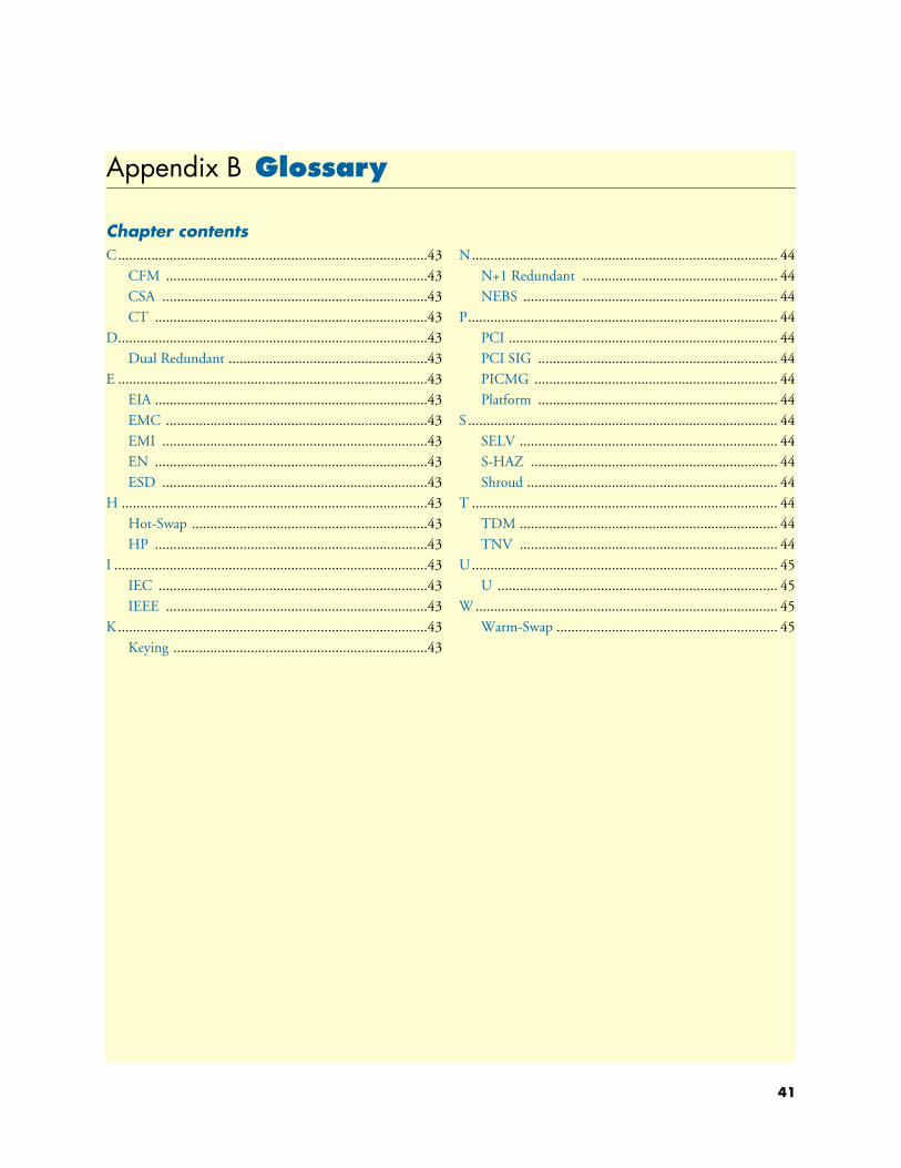
Chapter contentsC....................................................................................43
CFM .......................................................................43CSA ........................................................................43CT ..........................................................................43
D....................................................................................43Dual Redundant ......................................................43
E ....................................................................................43EIA ..........................................................................43EMC .......................................................................43EMI ........................................................................43EN ..........................................................................43ESD ........................................................................43
H ...................................................................................43Hot-Swap ................................................................43HP ..........................................................................43
I .....................................................................................43IEC .........................................................................43IEEE .......................................................................43
K ....................................................................................43Keying .....................................................................43
N................................................................................... 44N+1 Redundant ..................................................... 44NEBS ..................................................................... 44
P.................................................................................... 44PCI ......................................................................... 44PCI SIG ................................................................. 44PICMG .................................................................. 44Platform ................................................................. 44
S .................................................................................... 44SELV ...................................................................... 44S-HAZ ................................................................... 44Shroud .................................................................... 44
T ................................................................................... 44TDM ...................................................................... 44TNV ...................................................................... 44
U................................................................................... 45U ............................................................................ 45
W .................................................................................. 45Warm-Swap ............................................................ 45
41

B • Glossary Model 6676 6U CPCI Chassis Assembly User Guide
42
Model 6676 6U CPCI Chassis Assembly User Guide B • Glossary
C
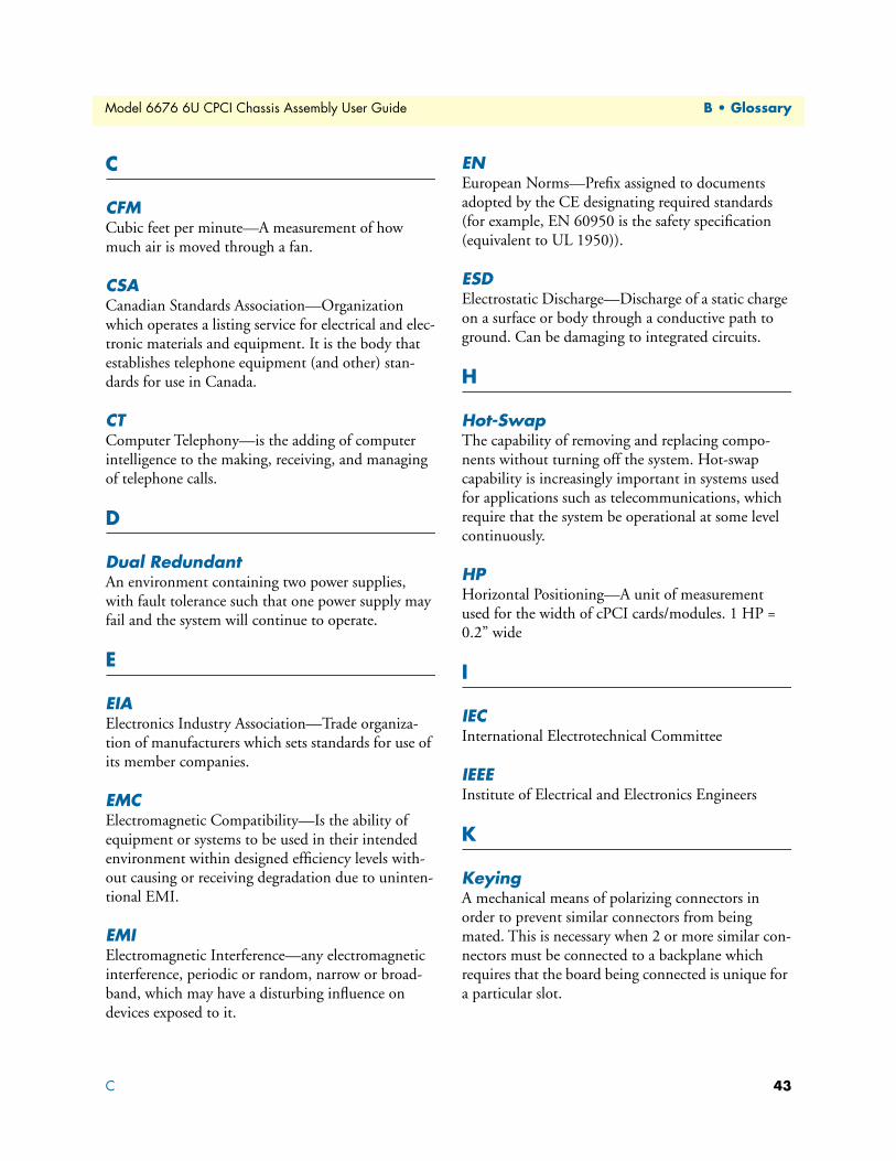
CFMCubic feet per minute—A measurement of how much air is moved through a fan.
CSACanadian Standards Association—Organization which operates a listing service for electrical and elec-tronic materials and equipment. It is the body that establishes telephone equipment (and other) stan-dards for use in Canada.
CTComputer Telephony—is the adding of computer intelligence to the making, receiving, and managing of telephone calls.
D
Dual RedundantAn environment containing two power supplies, with fault tolerance such that one power supply may fail and the system will continue to operate.
E
EIAElectronics Industry Association—Trade organiza-tion of manufacturers which sets standards for use of its member companies.
EMCElectromagnetic Compatibility—Is the ability of equipment or systems to be used in their intended environment within designed efficiency levels with-out causing or receiving degradation due to uninten-tional EMI.
EMIElectromagnetic Interference—any electromagnetic interference, periodic or random, narrow or broad-band, which may have a disturbing influence on devices exposed to it.
ENEuropean Norms—Prefix assigned to documents adopted by the CE designating required standards (for example, EN 60950 is the safety specification (equivalent to UL 1950)).
ESDElectrostatic Discharge—Discharge of a static charge on a surface or body through a conductive path to ground. Can be damaging to integrated circuits.
H
Hot-Swap The capability of removing and replacing compo-nents without turning off the system. Hot-swap capability is increasingly important in systems used for applications such as telecommunications, which require that the system be operational at some level continuously.
HPHorizontal Positioning—A unit of measurement used for the width of cPCI cards/modules. 1 HP = 0.2” wide
I
IECInternational Electrotechnical Committee
IEEEInstitute of Electrical and Electronics Engineers
K
KeyingA mechanical means of polarizing connectors in order to prevent similar connectors from being mated. This is necessary when 2 or more similar con-nectors must be connected to a backplane which requires that the board being connected is unique for a particular slot.
C 43
B • Glossary Model 6676 6U CPCI Chassis Assembly User Guide
N
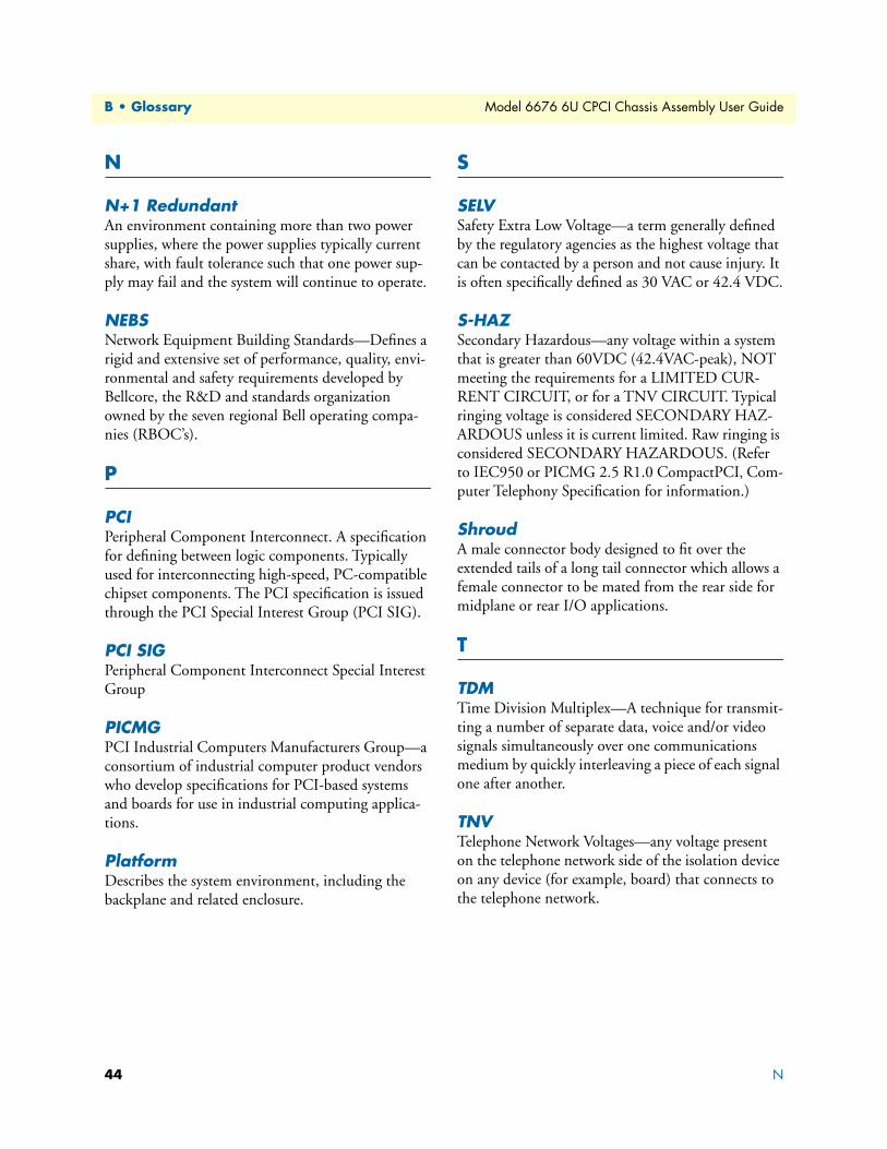
N+1 RedundantAn environment containing more than two power supplies, where the power supplies typically current share, with fault tolerance such that one power sup-ply may fail and the system will continue to operate.
NEBSNetwork Equipment Building Standards—Defines a rigid and extensive set of performance, quality, envi-ronmental and safety requirements developed by Bellcore, the R&D and standards organization owned by the seven regional Bell operating compa-nies (RBOC’s).
P
PCIPeripheral Component Interconnect. A specification for defining between logic components. Typically used for interconnecting high-speed, PC-compatible chipset components. The PCI specification is issued through the PCI Special Interest Group (PCI SIG).
PCI SIGPeripheral Component Interconnect Special Interest Group
PICMGPCI Industrial Computers Manufacturers Group—a consortium of industrial computer product vendors who develop specifications for PCI-based systems and boards for use in industrial computing applica-tions.
PlatformDescribes the system environment, including the backplane and related enclosure.
S
SELVSafety Extra Low Voltage—a term generally defined by the regulatory agencies as the highest voltage that can be contacted by a person and not cause injury. It is often specifically defined as 30 VAC or 42.4 VDC.
S-HAZSecondary Hazardous—any voltage within a system that is greater than 60VDC (42.4VAC-peak), NOT meeting the requirements for a LIMITED CUR-RENT CIRCUIT, or for a TNV CIRCUIT. Typical ringing voltage is considered SECONDARY HAZ-ARDOUS unless it is current limited. Raw ringing is considered SECONDARY HAZARDOUS. (Refer to IEC950 or PICMG 2.5 R1.0 CompactPCI‚ Com-puter Telephony Specification for information.)
ShroudA male connector body designed to fit over the extended tails of a long tail connector which allows a female connector to be mated from the rear side for midplane or rear I/O applications.
T
TDMTime Division Multiplex—A technique for transmit-ting a number of separate data, voice and/or video signals simultaneously over one communications medium by quickly interleaving a piece of each signal one after another.
TNVTelephone Network Voltages—any voltage present on the telephone network side of the isolation device on any device (for example, board) that connects to the telephone network.
44 N
Model 6676 6U CPCI Chassis Assembly User Guide B • Glossary
U
UAn EIA unit of measurement equal to 1.75 in. (4.45 cm) for equipment racks.
W
Warm-SwapAn environment supporting removal and insertion of power supplies while under power, wherein the power supply is disabled during insertion and removal, avoiding the need for the connectors to make and break high current connections while under load.
U 45

B • Glossary Model 6676 6U CPCI Chassis Assembly User Guide
46 W

Appendix C Bibliography
Chapter contentsPublications referenced in this guide......................................................................................................................48
47
C • Bibliography Model 6676 6U CPCI Chassis Assembly User Guide
Publications referenced in this guideThe following publications are used in conjunction with this manual.
• ECTF H.110 (CT Bus) Specification (Revision 1.0)
• CompactPCI Hot Swap Specification—PICMG 2.12 (Revision 1.0)
• CompactPCI Specification—PICMG 2.0 (Revision 3.0)
• Keying of CompactPCI Boards and Backplanes Specification—PICMG 2.10 (Revision 1.0)
• UL60950, Safety of Information Technology Equipment, including Electrical Business Equipment
• IEC 61076-4-101 (1995-05), Specification for 2mm Connector System
• IEEE 1101.10, IEEE Standard for Additional Mechanical Specifications for Microcomputers using IEEE 1101.1 Equipment Practice
48 Publications referenced in this guide