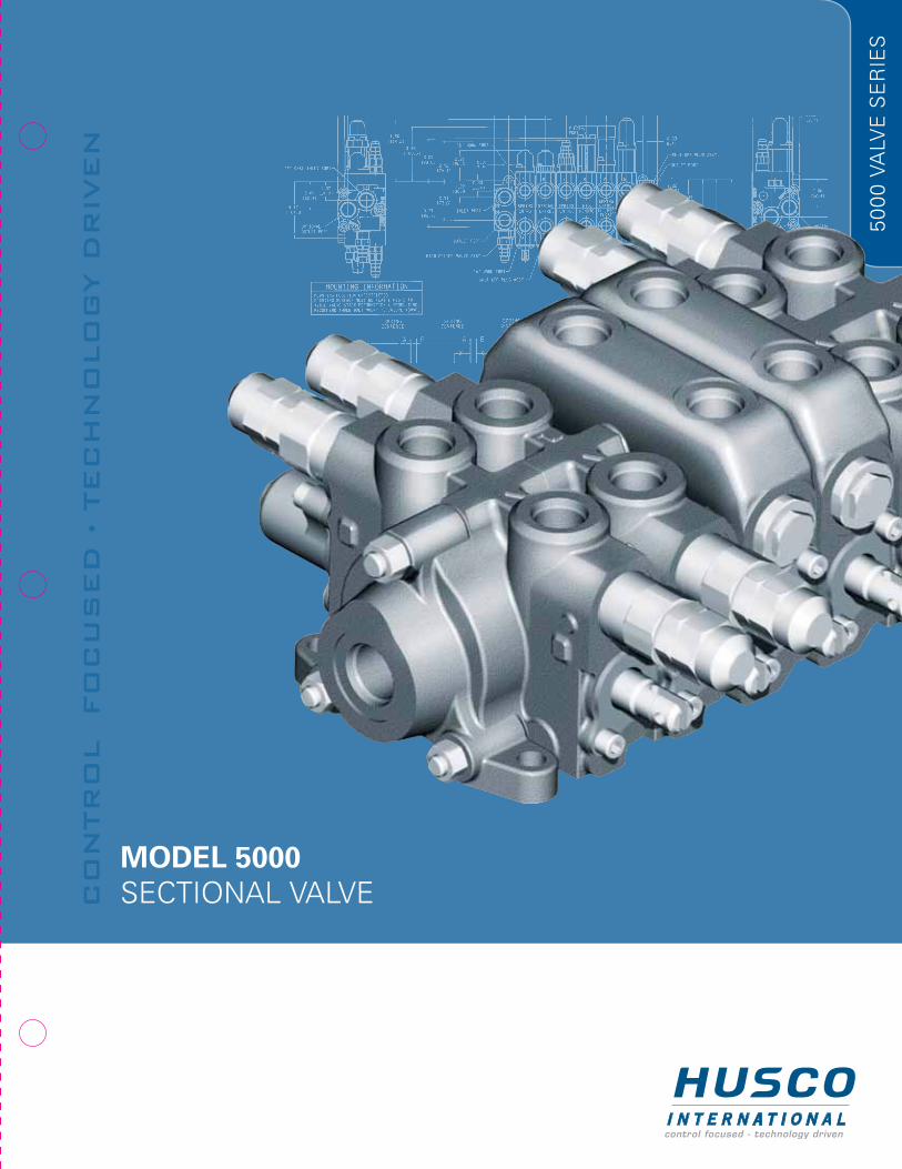
MODEL 5000 Sectional valve Control fo C used te C hnol og y driven
36
MODEL 5000 SECTIONAL VALVE CONTROL FOCUSED • TECHNOLOGY DRIVEN 5000 VALVE SERIES
Transcript of MODEL 5000 Sectional valve Control fo C used te C hnol og y driven
MODEL 5000 Sectional valveC
on
tr
ol
fo
Cu
sed
• t
eC
hn
olo
gy d
riv
en
50
00
va
lve
Se
rie
S

Inlet/Outlet SeCtIOn CutAWAY
Top Power Beyond PortunIVeRSAl Outlet/ POWeR BeYOnD SeCtIOn CutAWAY
Patented One O-Ring Seal Between Sections – an Industry Proven Leak-Free Design
“A” Work Port
PARAllel CIRCuIt SPOOl SeCtIOn CutAWAY
MODeL 5000SecTIOnAL cuTAWAy
Top Inlet Port
Top Outlet Port
Optional end Outlet Port
Optional end Inlet Port
Auxiliary Valve Port Accepts 5060 Style Main Relief
Auxiliary Port – See Pages 20-22 for
Work Port Options
Load check
O-Ring/Wiper Spool Seal
combination
Precision Spool with Metering
notches
“B” Work Port
Work Port Feeder core or “Bridge”
Spring centered end Mechanism–Many Other Options Available
Thru neutral Passage
Low Pressure or Tank Passage
Top Outlet Port
Optional end Outlet Port
Auxiliary Valve Port used to convert Valve for Power Beyond – See Page 18 for Other Options
Optional end Power Beyond Port
Parallel Passage

3
MODeL 5000
Since 1946, HuScO International has established itself as the resource OeM engineers rely on for help designing high quality, innovative, customized products that meet precision motion control requirements. This catalog fully illustrates the component features and options you need to specify, build and service a Model 5000 sectional body directional control valve.
Designed for hydraulic systems, the Model 5000 valve line is made from an assortment of valve component sections and options that deliver the desired control valve circuit to match your specific application.
FeAtuReS
• 3000 psi operating pressure rating (207 bar)
• Open-center or closed-center operation
• Hard chrome plated spools
• Load check in each section
• Single “low pressure” O-ring sealing between sections
• Precision spool with metering notches
OPtIOnS
• High pressure carryover (Power Beyond)
• Lock-out spool section (Built-in pilot operated check valve section)
• Mid-inlet flow combiner or separator
• Left-hand spool sections*
• Parallel, conventional and Series circuitry
• end mechanisms: – Spring centered – Detent – single or multi-position – 4th position float – Hydraulic remote – Pneumatic remote – Automatic kick-out
• Auxiliary valves: – Pilot-operated, anti-cavitation check combination; relief cartridges – Anti-cavitation; cartridges
• Regenerative spools*
• Specialized spools*
* consult HuScO

4
Features and Options 3Pressure Drop curves 5Technical Data 5Dimensional Data in Inches (Millimeters) 6Inlet end Section Assemblies (L.H. covers) 7-10 Inlet Sections 7 Inlet/Outlet Sections (cutaway photo pg. 19) 8 Mid-Inlet Sections 9-10Spool Section Assemblies 11-17 Parallel circuit Manually Operated Sections 11 Parallel circuit Manually Operated Lock-Out Spool Sections 12 Parallel circuit Hydraulic Remote Sections 13 Parallel circuit electric Sections 14 conventional circuit Manually Operated Sections (Tandem) 15 Series circuit Manually Operated Sections 16Outlet end Section Assemblies (R.H. covers) 17-20 end Outlet/Turnaround Sections/Top Outlet 17 Power Beyond/closed-center Sections 17 universal Outlet/Optional P.B. Sections (cutaway photo pg. 19) 18 cutaway photo of Inlet P/n – and Outlet P/n 19Relief Valve Assemblies 20-21Auxiliary Valve and Tie Rod Information 22Lever Assemblies 23-24end Mechanisms n Service and Kit Information n Restrictors 25-27 Spring ctr. n Detents n Detent/Float 25 Hydraulic Remote n Pneumatic Remote 26 Spring ctr. With Detents: In and Out, In Only, Out Only n Flow Restrictors 27
APPenDIceSAppendix 1 Automatic Kick-out Feature (ordering information pg. 15) 28Appendix 2 Spool end Orientation/cable connectors 29Appendix 3 Basic casting Identification 29Appendix 4 52250 Style Lever Parts Listing 30Appendix 5 P.O. Relief and Anti-Void Operation 31Appendix 6 P.O. Relief and Anti-Void Maintenance Procedure 32Appendix 7 Valve Assembly Procedure 33Appendix 8 Valve Assembly Specification Sheet 34
TABLe OF cOnTenTS PAge
APPenDIceS

5
THROugH neuTRAL THROugH neuTRAL
PReSSuRe DROP cuRVeS AnD TecHnIcAL DATA
Flow rating (nominal) ............................ 20 gpm (75 lpm)
Operating Pressure*.............................. 3000 psi (207 bar) (Method of verifying
rated fatigue pressure of the pressure containing envelope conforms to nFPA Recommended Std., nFPA/2.6.1 – 1974 category 1/90)
* Higher pressure applications consult HuScO
Seals...................................................... Buna-n Standard Vitron Optional
InLeT TO WORK PORT WORK PORT TO TAnK
Recommended Filtration ....................................................... ISO 20/18/13
Maximum number of spool sections (any combination of) per valve assembly..... 11
Maximum outlet port/tank core (return) pressure ................................... 500 psi
We reserve the right to amend these specifications at any time without notice. The only warranty applicable is our standard written warranty. We make no other warranty, expressed or implied.
Performance characteristics shown are typical of production units tested in the laboratory and are not necessarily representative of any one unit.

6
MODeL 5000 VALVe ASSeMBLy

7
InLeT SecTIOn ASSeMBLIeS
WeIgHT: APPROx. 2 LBS. [0.9 kg]
WITH enD PORT. nO AuxILIARy VALVe PORT OPTIOn (FOR APPLIcATIOnS THAT DO nOT ReQuIRe A MAIn ReLIeF VALVe AT THe VALVe ASSeMBLy)

8
InLeT / OuTLeT SecTIOn ASSeMBLIeS
WeIgHT: APPROx. 3.1 LBS. [1.4 kg]
WITH AuxILIARy VALVe PORT FOR MAIn ReLIeF VALVe.TOP InLeT/OuTLeT PORTS OPTIOnAL enD InLeT/OuTLeT PORTS

9
MID- InLeT cOMBIneR SecTIOn ASSeMBLy
WeIgHT: APPROx. 2.5 LBS. [1.1 kg]
MID-InLeT PuMP FLOW cOMBIneS WITH uPSTReAM PuMP FLOW TO FeeD DOWnSTReAM SPOOL SecTIOnS. WHen
uPSTReAM SPOOL SecTIOnS ARe AcTIVATeD. DOWnSTReAM SPOOL SecTIOnS ARe exPOSeD TO MID-InLeT PuMP FLOW OnLy.

10
MID- InLeT SePARATe FLOW SecTIOn ASSeMBLy
WeIgHT: APPROx. 2.5 LBS. [1.1 kg]
MID-InLeT PuMP FLOW FeeDS DOWnSTReAM SPOOL SecTIOnS.uPSTReAM PuMP FLOW TO LOW PReSSuRe.

11
PARALLeL c IRcuIT MAnuALLy OPeRATeD SPOOL SecTIOn ASSeMBLIeS
WeIgHT: APPROx. 5.1 LBS. [2.3 kg] **WeIgHT: APPROx. 5.4 LBS. [2.4 kg]

12
PARALLeL c IRcuIT MAnuALLy OPeRATeD LOcK-OuT SPOOL SecTIOn ASSeMBLy
WeIgHT: APPROx. 6.9 LBS. [3.1 kg]
(PILOT OPeRATeD cHecK SecTIOn)

13
PARALLeL c IRcuIT HyDRAuLIc ReMOTe (O IL P ILOT OPeRATeD) SPOOL SecTIOn ASSeMBLIeS
WeIgHT: APPROx. 6.0 LBS. [2.7 kg]

14
PARALLeL c IRcuIT eLecTRIc SPOOL SecTIOn ASSeMBLIeS
WeIgHT: APPROx. 5.6 LBS. [2.5 kg]

15
cOnVenTIOnAL c IRcuIT MAnuALLy OPeRATeD SPOOL SecTIOn ASSeMBLIeS (TAnDeM)
WeIgHT: APPROx. 5.1 LBS. [2.3 kg] **WeIgHT: APPROx. 5.6 LBS. [2.5 kg]

16
SeRIeS c IRcuIT MAnuALLy OPeRATeD SPOOL SecTIOn ASSeMBLIeS
WeIgHT: APPROx. 5.1 LBS. [2.3 kg]
17
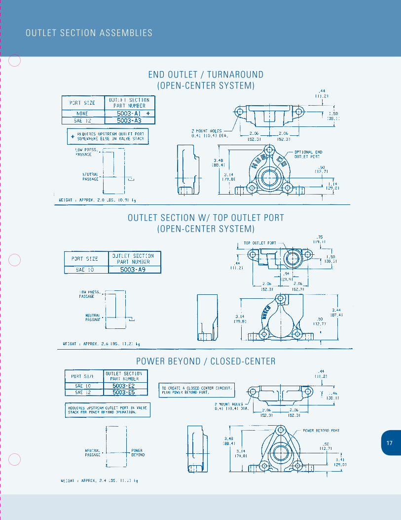
OuTLeT SecTIOn ASSeMBLIeS
enD OuTLeT / TuRnAROunD(OPen-cenTeR SySTeM)
OuTLeT SecTIOn W/ TOP OuTLeT PORT(OPen-cenTeR SySTeM)
POWeR BeyOnD / cLOSeD-cenTeR

18
unIVeRSAL OuTLeT / POWeR BeyOnD OPTIOn SecTIOn ASSeMBLIeS
WeIgHT: APPROx. 3.0 LBS. [1.4 kg]

19
cuTAWAy VIeW AnD DOWnSTReAM VIeW (“O”-R Ing FAce) OF InLeT enD SecTIOn ASSeMBLy P/n 5001-A88
cuTAWAy VIeW AnD uPSTReAM VIeW (nOn-“O”-R Ing FAce) OF OuTLeT enD SecTIOn ASSeMBLy P/n 5003-A68
THe InLeT PORTS cOMMunIcATe OIL TO THe THRu neuTRAL PASSAge AnD THe PARALLeL PASSAge. THe OuTLeT PORTS cOMMunIcATe OIL FROM THe LOW PReSSuRe OR TAnK PASSAge.
InLeT PORTS OuTLeT PORT
OuTLeT PORT
MAIn ReLIeF
PARALLeL PASSAge
OuTLeT InLeT
THRu neuTRALPASSAge
LOW PReSSuRe OR TAnK PASSAge
OuTLeT PORT
A SHuT-OFF PLug P/n 52610 IS PLAceD In THe AuxILIARy PORT TO DIRecT THe THRu neuTRAL PASSAge TO HIgH PReSSuRe POWeR BeyOnD. POWeR BeyOnD IS AcTIVe WHen ALL THe SPOOLS In THe VALVe ASSeMBLy ARe In THe neuTRAL POSITIOn.*
* exception: series circuit valve section assemblies return discharged oil to neutral passage. (See page 18 for other circuit options)
OuTLeT PORTHIgH PReSSuRe POWeR BeyOnD
PORTS
PARALLeL PASSAge FROM LAST PARALLeL
SPOOL SecTIOn WILL enD HeRe THRu
neuTRAL PASSAge
LOW PReSSuRe OR
TAnK PReSSuRe

20
ReL IeF VALVe ASSeMBLIeS
MODeL 5060 PILOT OPeRATeD ReLIeF VALVe WITH AnTI-VOID

21
ReL IeF VALVe ASSeMBLIeS
MODeL 52710 DIRecT AcTIng ReLIeF VALVe

22
AuxIL IARy VALVe AnD T Ie ROD InFORMATIOn
AnTI-cAVITATIOn cHecK VALVe

23
LeVeR ASSeMBLIeS
FIxeD POSITIOn LeVeR W/BOOTnOTe: See APPenDIx 3 FOR PARTS LISTIng

24
LeVeR ASSeMBLIeS
HeAVy DuTy MecHAnIcAL JOySTIcKFOR SIMuLTAneOuS cOnTROL OF TWO SPOOL SecTIOnS
InFInITe POSITIOn LeVeR

25
enD MecHAnISM KITS
FOR PARALLeL AnD cOnVenTIOnAL cIRcuIT SecTIOnS

26
enD MecHAnISM KITS
HyDRAuLIc ReMOTe (OIL PILOT OPeRATeD)

27
enD MecHAnISM KITS
FOR PARALLeL AnD cOnVenTIOnAL cIRcuIT SecTIOnS
FLOW ReSTRIcTORS

28
AuTOMATIc K IcK-OuT FeATuRe
APPenDIx 1
The auto kick-out feature, more commonly used and available on conventional circuit spool section assemblies, is an optional spool end mechanism. The auto kick-out mechanism combines a spring centered mechanism with a spool dented “in” and “out” mechanism that will release the spool to the center position at a pre-determined settable cylinder port pressure.
The illustration below identifies the working components of the auto kick-out mechanism. The auto kick-out mechanism is not available in kit conversion form because it requires a special valve section housing for its operation. consult HuScO for disassembly and reassembly maintenance procedures.
AuTO KIcK-OuT SeTTIng AnD ADJuSTMenTAdjustments to the auto kick-out valve section are made when integrated within a hydraulic circuit.
1. Install a pressure gage in the valve assembly inlet or a cylinder port line which is in communication with the auto kick-out valve section to be adjusted.
2. With the hydraulic system off, shift auto kick-out valve section to a detented position.
3. Activate the hydraulic system at a reduced pressure below that of the desired setting. Let the cylinder bottom out or plug the cylinder port to allow pressure build-up for kick-out activation. Slowly increase the hydraulic system pressure (the main system relief may be used for the purpose) until the auto kick-out activates and the spool returns to the center neutral position. Do not exceed system capability. note the pressure reading at time of kick-out; this will determine its current setting. Standard factory setting, if not specified, is 2000 PSI.
4. To make adjustments, remove rubber plug (P/n 4938) from end cap to access adjustment screw (P/n 5258). With hydraulic system off, turn adjustment screw clockwise (in) to increase the pressure setting; counterclockwise (out) to decrease pressure setting. Repeat Procedure #3 above until desired setting is achieved. Adjustment range is 1000-2600 PSI. Run a few cycles to assure setting consistency, replace rubber plug. note: Final main relief setting must be at least 250 PSI higher than the highest auto kick-out setting in the system.
caution: To avoid damaged or lost parts do not remove adjustment screw.

29
APPenDIx 2 SPOOL enD ORIenTATIOn
APPenDIx 3 BASIc cASTIng IDenTIF IcATIOn

30
LeVeR ASSeMBLIeS – PARTS L IST Ing
APPenDIx 4

31
SeRVIce InFORMATIOn
APPenDIx 5
AS WORK PORT ReLIeFThe relief valve is in communication between the high pressure port “HP” and low pressure “LP”. Oil is admitted through the hole in poppet “c” and because of the differential area between diameters “A” and “B” relief valve poppet “D” and check valve poppet “K” are tightly seated as shown in the first step.
The oil pressure in the high pressure port “HP” has reached the setting of the pilot poppet spring force and unseats the pilot poppet “e.” Oil flows around the poppet – through the cross drilled holes and to the low pressure area “LP.”
The loss of oil behind Poppet “c,” effected by the opening of pilot poppet “e,” causes poppet “c” to move back and seat against pilot poppet “e.” This shuts off the oil flow to the area behind relief valve poppet “D,” and causes a low pressure area internally.
The imbalance of pressure on the inside as compared to that of the high pressure port “HP,” forces the relief valve poppet “D” to open and relieve the oil directly to the low pressure chamber “LP” in the valve.
AS AnTI-VOIDThe anti-void unit supplies oil to the high pressure port “HP” when cavitation has occurred. A lower pressure exists in the port “HP” compared to the low pressure chamber “LP.” The difference between the effective area of diameter “A” and “g” causes imbalance of the check valve poppet “K” which unseats, thus allowing oil from the low pressure chamber “LP” to enter the port “HP” and fill the void.
AS SePARATe AnTI-VOIDThe anti-void check valve opens when cavitation occurs in the high pressure port “HP” and supplies oil from the reservoir “LP” to help fill this void. The poppet “M” is held on its seat by the port pressure “HP,” acting on the larger area behind the O-ring. When pressure “HP” drops below atmosphere, the tank pressure “LP” operating on the annular area A1-A2 will overcome the port pressure “HP” and the spring force to open the poppet. When the void is eliminated the spring will return the poppet which will then be tightly seated by the port pressure “HP.”
check HuScO first for modern hydraulic/electrohydraulic components and systems engineered to your specific needs.

32
APPenDIx 6 MAInTenAnce PROceDuRe
HOW TO SeT PReSSuRe On WORK PORT ReLIeF
A good pressure gage must be installed in the line which is in communication with the work port relief. A load must be applied in a manner to reach the set pressure of the port relief unit. Then, follow these steps: • Remove acorn nut and loosen lock nut • Set adjusting screw to desired pressure setting • Tighten lock nut and reassemble acorn nut • Retest in similar manner as above
The Void control Feature is not adjustable but is designed to operate whenever the work port pressure is lower than the reservoir pressure.
SeRVIce AnD RePAIR InFORMATIOn
The cartridge type work port reliefs used in the HuScO valves are typically of the pilot poppet type with external adjustment. Any malfunctioning is usually the result of foreign matter lodging between the piston, relief valve poppet, and check valve.
To perform service, clean the surrounding area and remove the complete relief valve cartridge. examine the seat in the main valve housing and if grooves or ridges are present, the valve must be returned to HuScO for re-machining.
The design of the pilot poppet and its seat provides positive seating and very seldom requires any maintenance. Therefore, the pilot section can be removed from the cartridge housing without disturbing the setting. With it will come the check valve poppet and other internal parts. These are easily disassembled and should be examined for foreign matter. All seats and seating surfaces should be smooth and free of nicks, scratches or grooves. examine O-rings and back up washers for any damage and replace if necessary. All moving parts should slide freely, with only seal friction being present.
After inspecting and cleaning, immerse all parts in hydraulic oil and reassemble. Since pressure setting was not disturbed, unit can be tested for proper functioning under actual working conditions.
If operating difficulties indicate that the pilot poppet is leaking or sticking, remove internal parts of the pilot section, and follow the same procedure as above plus follow “How to Set Pressure” previously discussed.
If unit still does not function properly, you may wish to return the cartridge to HuScO.
HuScO cOMBInATIOn WORK PORT ReLIeF AnD AnTI-VOID unIT
DIFFIcuLTy PROBABLe cAuSe ReMeDy can’t get Pressure Poppet D, e or K stuck open or contamination check for foreign matter between poppets D, e or K and under seat. their mating parts. Parts must slide freely.
erratic Pressure Pilot poppet seat damaged. Replace the relief valve. Poppet c sticking in D. clean and remove surface marks for free movement.
Pressure setting normal wear. Lock nut & adj. screw loose. See “How to set pressure on work port relief.” not correct
Leaks Damaged seats. Replace the relief valve. Worn O-rings. Install seal and spring kit. Parts sticking due to contamination. Disassemble and clean.
TROuBLe SHOOTIng – AnTI-VOID
Trouble resulting in malfunctioning can usually be traced to foreign matter plugging and sensing hole or preventing free movement of poppet. Also check seat for scratches, nicks or other marks.
SHuT-OFF VALVeShut-off valves are available to fit most work port and main relief valve machining locations.
Authorized Permission For Reprinting Must Be granted By HuScO. gFI-3M0593

33
APPenDIx 7 ASSeMBLy PROceDuReS FOR THe HuScO 5000 VALVe
1. Lay out valve components on a clean, flat working surface. The inlet assembly will include an O-ring, and the spool section(s) include an O-ring, a load check poppet and a load check spring. Tools required for basic valve assembly include 1/2” and 9/16” open or box end wrenches and a torque wrench with thin wall sockets.
2. Assemble tie rod nuts to one end of each tie rod with one or two threads showing. Insert tie rods through tie rod holes of inlet (larger tie rod at top). Lay inlet on end with tie rods up, place O-ring into position.
3. Place first spool section (O-ring side up) on inlet section, position O-ring and insert load check poppet (nose down) and spring (behind poppet) into load check cavity as shown. Repeat this procedure for each spool section; the load check springs are compressed by the following sections during assembly.
4. Position end section on last spool section as shown and hand tighten tie rod nuts. The end section is a “turn around” section without ports. universal outlet / power beyond section and power beyond and closed center sections are also used as end sections. These end sections do not have O-ring grooves.
5. Position valve assembly with the mounting pads of the end sections on a flat surface. To obtain proper alignment of end sections relative to the spool sections apply downward pressure to the end sections; snug tie rod nuts to about 10 ft-lb.
Final torque the two 1/2” nuts to 14 ft-lb; final torque the 9/16” nut to 33 ft-lb. check for proper spool movement.
6. Install auxiliary valves and plugs and torque to proper specifications.
geneRAL ASSeMBLy nOTeS:A. Lever assemblies can be installed on section before or after complete
valve assembly.
B. The load check and spring may be omitted from assembly in certain conditions (i.e., motor spools).

34
APPenDIx 8 MODeL 5000 SecTIOnAL VALVe ASSeMBLy SPecIF IcATIOn SHeeT

cOnTROL FOcuSeD - TecHnOLOgy DRIVen
For over 50 years, HuScO International has been designing and producing some of the
most important custom hydraulic and electrohydraulic products in the construction,
forestry and material handling industry. Today HuScO control products can be found on
a variety of leading off-highway equipment including: caterpillar, cnH, crown, Daewoo,
Deere & company, Hyundai, JcB, Jerr-Dan, JLg, Komatsu, Kubota, Liebherr, Manitowoc
crane group, nAccO, Volvo, Terex, just to name a few.
Dedicated to meeting and exceeding the changing control needs of the off-highway
market for today and well into tomorrow, HuScO employs an extensive engineering staff
capable of designing customized, cost-effective solutions to maximize the efficiency,
productivity, controllability and reliability of vehicles.
And with vehicle fit-up and testing capabilities, we’re able to design, install and test
valve configurations at HuScO facilities, reducing product development time while
optimizing vehicle performance through iterative testing.
With manufacturing facilities in north America, europe and Asia, we continue to expand
as we work with international partners in South America, Korea, Japan, India, South
Africa and Australia to bring you any product you need, anywhere in the world.

Co
ntr
ol f
oC
us
ed
teC
hn
olo
gy d
riv
en
AMERICAHUSCO International
W239 n218 Pewaukee roadWaukesha, Wisconsin 53188 USa
telephone +01-262-513-4200 | Fax +01-262-513-4427www.huscointl.com
EUROPEHUSCO International, Ltd.
6 rivington roadWhitehouse industrial estate
runcorn, cheshire Wa7 3Dt englandtelephone +44-1928-701888 | Fax +44-1928-710813
ASIAHUSCO-Kayaba Hydraulics (Shanghai) Ltd.
no. 235 Jiangtian road eastSong Jiang industrial Zone
Shanghai 201600 chinatelephone +86-21-5774-6468 | Fax +86-21-3774-0186
© 2005 HuScO International