Model 4200A-SCS Parameter Analyzer Users Manual
138
User’s Manual 4200A-900-01 Rev. D April 2020 *P4200A-900-01D* 4200A-900-01D tek.com/keithley Model 4200A-SCS Parameter Analyzer
Transcript of Model 4200A-SCS Parameter Analyzer Users Manual

User’s Manual4200A-900-01 Rev. D April 2020
*P4200A-900-01D*4200A-900-01D
tek.com/keithley
Model 4200A-SCS Parameter Analyzer

Parameter Analyzer
User's Manual
4200A-SCS

© 2020, Keithley Instruments
Cleveland, Ohio, U.S.A.
All rights reserved.
Any unauthorized reproduction, photocopy, or use of the information herein, in whole or in part,
without the prior written approval of Keithley Instruments is strictly prohibited.
All Keithley Instruments product names are trademarks or registered trademarks of Keithley
Instruments, LLC. Other brand names are trademarks or registered trademarks of their respective
holders.
Actuate®
Copyright © 1993-2003 Actuate Corporation.
All Rights Reserved.
Microsoft, Visual C++, Excel, and Windows are either registered trademarks or trademarks of
Microsoft Corporation in the United States and/or other countries.
Document number: 4200A-SCS-900-01 Rev. D / April 2020

Safety precautions
The following safety precautions should be observed before using this product and any associated instrumentation. Although some instruments and accessories would normally be used with nonhazardous voltages, there are situations where hazardous conditions may be present.
This product is intended for use by personnel who recognize shock hazards and are familiar with the safety precautions required to avoid possible injury. Read and follow all installation, operation, and maintenance information carefully before using the product. Refer to the user documentation for complete product specifications.
If the product is used in a manner not specified, the protection provided by the product warranty may be impaired.
The types of product users are:
Responsible body is the individual or group responsible for the use and maintenance of equipment, for ensuring that the equipment is operated within its specifications and operating limits, and for ensuring that operators are adequately trained.
Operators use the product for its intended function. They must be trained in electrical safety procedures and proper use of the instrument. They must be protected from electric shock and contact with hazardous live circuits.
Maintenance personnel perform routine procedures on the product to keep it operating properly, for example, setting the line voltage or replacing consumable materials. Maintenance procedures are described in the user documentation. The procedures explicitly state if the operator may perform them. Otherwise, they should be performed only by service personnel.
Service personnel are trained to work on live circuits, perform safe installations, and repair products. Only properly trained service personnel may perform installation and service procedures.
Keithley products are designed for use with electrical signals that are measurement, control, and data I/O connections, with low transient overvoltages, and must not be directly connected to mains voltage or to voltage sources with high transient overvoltages. Measurement Category II (as referenced in IEC 60664) connections require protection for high transient overvoltages often associated with local AC mains connections. Certain Keithley measuring instruments may be connected to mains. These instruments will be marked as category II or higher.
Unless explicitly allowed in the specifications, operating manual, and instrument labels, do not connect any instrument to mains.
Exercise extreme caution when a shock hazard is present. Lethal voltage may be present on cable connector jacks or test fixtures. The American National Standards Institute (ANSI) states that a shock hazard exists when voltage levels greater than 30 V RMS, 42.4 V peak, or 60 VDC are present. A good safety practice is to expect that hazardous voltage is present in any unknown circuit before measuring.
Operators of this product must be protected from electric shock at all times. The responsible body must ensure that operators are prevented access and/or insulated from every connection point. In some cases, connections must be exposed to potential human contact. Product operators in these circumstances must be trained to protect themselves from the risk of electric shock. If the circuit is capable of operating at or above 1000 V, no conductive part of the circuit may be exposed.
Do not connect switching cards directly to unlimited power circuits. They are intended to be used with impedance-limited sources. NEVER connect switching cards directly to AC mains. When connecting sources to switching cards, install protective devices to limit fault current and voltage to the card.
Before operating an instrument, ensure that the line cord is connected to a properly-grounded power receptacle. Inspect the connecting cables, test leads, and jumpers for possible wear, cracks, or breaks before each use.
When installing equipment where access to the main power cord is restricted, such as rack mounting, a separate main input power disconnect device must be provided in close proximity to the equipment and within easy reach of the operator.
For maximum safety, do not touch the product, test cables, or any other instruments while power is applied to the circuit under test. ALWAYS remove power from the entire test system and discharge any capacitors before: connecting or disconnecting cables or jumpers, installing or removing switching cards, or making internal changes, such as installing or removing jumpers.
Do not touch any object that could provide a current path to the common side of the circuit under test or power line (earth) ground. Always make measurements with dry hands while standing on a dry, insulated surface capable of withstanding the voltage being measured.

For safety, instruments and accessories must be used in accordance with the operating instructions. If the instruments or accessories are used in a manner not specified in the operating instructions, the protection provided by the equipment may be impaired.
Do not exceed the maximum signal levels of the instruments and accessories. Maximum signal levels are defined in the specifications and operating information and shown on the instrument panels, test fixture panels, and switching cards.
When fuses are used in a product, replace with the same type and rating for continued protection against fire hazard.
Chassis connections must only be used as shield connections for measuring circuits, NOT as protective earth (safety ground) connections.
If you are using a test fixture, keep the lid closed while power is applied to the device under test. Safe operation requires the use of a lid interlock.
If a screw is present, connect it to protective earth (safety ground) using the wire recommended in the user documentation.
The symbol on an instrument means caution, risk of hazard. The user must refer to the operating instructions located in the user documentation in all cases where the symbol is marked on the instrument.
The symbol on an instrument means warning, risk of electric shock. Use standard safety precautions to avoid personal contact with these voltages.
The symbol on an instrument shows that the surface may be hot. Avoid personal contact to prevent burns.
The symbol indicates a connection terminal to the equipment frame.
If this symbol is on a product, it indicates that mercury is present in the display lamp. Please note that the lamp must be properly disposed of according to federal, state, and local laws.
The WARNING heading in the user documentation explains hazards that might result in personal injury or death. Always read the associated information very carefully before performing the indicated procedure.
The CAUTION heading in the user documentation explains hazards that could damage the instrument. Such damage may invalidate the warranty.
The CAUTION heading with the symbol in the user documentation explains hazards that could result in moderate or minor injury or damage the instrument. Always read the associated information very carefully before performing the indicated procedure. Damage to the instrument may invalidate the warranty.
Instrumentation and accessories shall not be connected to humans.
Before performing any maintenance, disconnect the line cord and all test cables.
To maintain protection from electric shock and fire, replacement components in mains circuits — including the power transformer, test leads, and input jacks — must be purchased from Keithley. Standard fuses with applicable national safety approvals may be used if the rating and type are the same. The detachable mains power cord provided with the instrument may only be replaced with a similarly rated power cord. Other components that are not safety-related may be purchased from other suppliers as long as they are equivalent to the original component (note that selected parts should be purchased only through Keithley to maintain accuracy and functionality of the product). If you are unsure about the applicability of a replacement component, call a Keithley office for information.
Unless otherwise noted in product-specific literature, Keithley instruments are designed to operate indoors only, in the following environment: Altitude at or below 2,000 m (6,562 ft); temperature 0 °C to 50 °C (32 °F to 122 °F); and pollution degree 1 or 2.
To clean an instrument, use a cloth dampened with deionized water or mild, water-based cleaner. Clean the exterior of the instrument only. Do not apply cleaner directly to the instrument or allow liquids to enter or spill on the instrument. Products that consist of a circuit board with no case or chassis (e.g., a data acquisition board for installation into a computer) should never require cleaning if handled according to instructions. If the board becomes contaminated and operation is affected, the board should be returned to the factory for proper cleaning/servicing.
Safety precaution revision as of June 2017.


Introduction .............................................................................................................. 1-1
Welcome .............................................................................................................................. 1-1
Introduction to this manual ................................................................................................... 1-1
Extended warranty ............................................................................................................... 1-2
Contact information .............................................................................................................. 1-2
Organization of manual sections .......................................................................................... 1-2
Application examples ........................................................................................................... 1-3
General ratings ..................................................................................................................... 1-3
Getting started ......................................................................................................... 2-1
Front panel overview ............................................................................................................ 2-1 Touchscreen basics .................................................................................................................. 2-2 Connect a keyboard and mouse ............................................................................................... 2-3
Rear panel overview ............................................................................................................ 2-4 Connect an external monitor ..................................................................................................... 2-5
Installation ............................................................................................................................ 2-6 Locating the system .................................................................................................................. 2-6 Basic system connections ......................................................................................................... 2-7 SMU connections .................................................................................................................... 2-11 Powering the 4200A-SCS ....................................................................................................... 2-16
Create a new project and test .................................................................................. 3-1
Introduction .......................................................................................................................... 3-1
Equipment required .............................................................................................................. 3-1
Device connections .............................................................................................................. 3-2 Connection schematic ............................................................................................................... 3-2 Connect the 4200A-SCS to the DUT ......................................................................................... 3-3
Set up the measurements in Clarius .................................................................................... 3-3 Select and rename a new project .............................................................................................. 3-4 Add a device ............................................................................................................................. 3-5 Select a custom test .................................................................................................................. 3-6 Configure the test ...................................................................................................................... 3-6 Execute the test ........................................................................................................................ 3-9 View and analyze the test results .............................................................................................. 3-9
Use the RPM to switch the SMU, CVU, and PMU ................................................... 4-1
Introduction .......................................................................................................................... 4-1
Equipment required .............................................................................................................. 4-2
Update the RPM configuration in KCon ............................................................................... 4-2
Device connections .............................................................................................................. 4-3 Connection schematic ............................................................................................................... 4-4 Connect the 4200A-SCS to the DUT ......................................................................................... 4-5
Table of contents

Table of contents 4200A-SCS Parameter Analyzer User's Manual
Set up the measurements in Clarius .................................................................................... 4-5 Create a new project ................................................................................................................. 4-6 Add a device ............................................................................................................................. 4-7 Search for and select existing tests in the Test Library ............................................................. 4-8 Configure the vfd test ................................................................................................................ 4-9 Configure the cv-diode test ..................................................................................................... 4-12 Configure the pulse-diode test ................................................................................................ 4-15 Run the test ............................................................................................................................. 4-18 View and analyze the test results ............................................................................................ 4-18
Configure and use a Series 700 Switching System ............................................... 5-1
Introduction .......................................................................................................................... 5-1
Equipment required .............................................................................................................. 5-2
Device connections .............................................................................................................. 5-2 Connect the 7072 to the DUT.................................................................................................... 5-3 Connect the 4200A-SCS to the 7072 ........................................................................................ 5-4
Update the switch configuration in KCon ............................................................................. 5-6
Set up the measurements in Clarius .................................................................................. 5-11 Create a new project ............................................................................................................... 5-11 Add a device ........................................................................................................................... 5-12 Add the connectpins action ..................................................................................................... 5-12 Configure the connectpins action ............................................................................................ 5-13 Search for and add existing tests from the Test Library .......................................................... 5-16 Run the project and view the tests .......................................................................................... 5-17
Make I-V measurements on a solar cell .................................................................. 6-1
Introduction .......................................................................................................................... 6-1
Equipment required .............................................................................................................. 6-1
Device connections .............................................................................................................. 6-2 Device connection schematic .................................................................................................... 6-2 Connect the 4200A-SCS to the DUT ......................................................................................... 6-3
Setting up measurements in the Clarius software ............................................................... 6-4 Create a new project ................................................................................................................. 6-4 Search for and select a test....................................................................................................... 6-5 Configure the test ...................................................................................................................... 6-6 Run the test ............................................................................................................................... 6-9 Analyze the test results ............................................................................................................. 6-9 Additional tests ........................................................................................................................ 6-10
Make C-V measurements on a MOSCAP ................................................................ 7-1
Introduction .......................................................................................................................... 7-1
Equipment required .............................................................................................................. 7-1
Device connections .............................................................................................................. 7-2 Connect the 4200A-SCS to the DUT ......................................................................................... 7-3
Set up the measurements in Clarius .................................................................................... 7-4 Search for and select a project .................................................................................................. 7-4 Configure the test ...................................................................................................................... 7-5 Perform offset compensation .................................................................................................. 7-10 Run the test ............................................................................................................................. 7-14

4200A-SCS Parameter Analyzer User's Manual Table of contents
View and analyze the test results ............................................................................................ 7-14
Use the 4200A-CVIV Multi-Switch ........................................................................... 8-1
Introduction .......................................................................................................................... 8-1
Equipment required .............................................................................................................. 8-2
Device connections .............................................................................................................. 8-2 Connection schematic ............................................................................................................... 8-3
Set up the measurements in Clarius .................................................................................... 8-4 Create and rename a project for I-V and C-V measurements with compensation ..................... 8-5 Add an action to perform CVU compensation ........................................................................... 8-6 Configure the action .................................................................................................................. 8-6 Add a device ............................................................................................................................. 8-9 Add an action for switching the SMUs to the device ................................................................. 8-9 Configure the action ................................................................................................................ 8-10 Add a test for making I-V measurements ................................................................................ 8-11 Add an action for switching the CVU to the output terminals of the 4200A-CVIV .................... 8-12 Configure the action ................................................................................................................ 8-13 Add a test for making C-V measurements .............................................................................. 8-14 Run the project and review the results .................................................................................... 8-17
PMU for pulsed I-V measurements on a MOSFET ................................................. 9-1
Introduction .......................................................................................................................... 9-1
Equipment required .............................................................................................................. 9-2
Device connections .............................................................................................................. 9-2 Connection schematic ............................................................................................................... 9-3
Set up the measurements in Clarius .................................................................................... 9-4 Create a new project ................................................................................................................. 9-5 Search for and select an existing test ....................................................................................... 9-6 Configure the test ...................................................................................................................... 9-6 Run the test and analyze the results ......................................................................................... 9-9
Next steps ............................................................................................................... 10-1
Additional information ......................................................................................................... 10-1


In this section:
Welcome .................................................................................. 1-1 Introduction to this manual ....................................................... 1-1 Extended warranty ................................................................... 1-2 Contact information .................................................................. 1-2 Organization of manual sections .............................................. 1-2 Application examples ............................................................... 1-3 General ratings ......................................................................... 1-3
Welcome
Thank you for choosing a Keithley Instruments product. The Model 4200A-SCS Parameter Analyzer
performs laboratory-grade DC, I-V, C-V, and pulse device characterization, real-time plotting, and
analysis with high precision and subfemtoamp resolution. The 4200A-SCS offers the most advanced
capabilities available in a fully integrated characterization system, including a complete, embedded
computer with Microsoft® Windows® operating system and mass storage. Its touchscreen interface
accelerates and simplifies the process of taking data, so users can begin analyzing their results
sooner. Additional features enable stress-measure capabilities suitable for a variety of reliability tests.
Introduction to this manual
This manual provides detailed applications to help you achieve success with your Keithley
Instruments 4200A-SCS. In addition, information is provided about the basics of the front panel to
familiarize you with the instrument. Finally, included is an overview of each application, followed by
instructions to complete the application.
More information about the commands that are used in these applications is available. Refer to the
Model 4200A-SCS Reference Manual, available from the Learning Center on your 4200A-SCS
desktop.
Section 1
Introduction

Section 1: Introduction 4200A-SCS Parameter Analyzer User's Manual
1-2 4200A-900-01 Rev. D/April 2020
Extended warranty
Additional years of warranty coverage are available on many products. These valuable contracts
protect you from unbudgeted service expenses and provide additional years of protection at a fraction
of the price of a repair. Extended warranties are available on new and existing products. Contact your
local Keithley Instruments office, sales partner, or distributor for details.
Contact information
If you have any questions after you review the information in this documentation, please contact your
local Keithley Instruments office, sales partner, or distributor. You can also call the Tektronix
corporate headquarters (toll-free inside the U.S. and Canada only) at 1-800-833-9200. For worldwide
contact numbers, visit tek.com/contact-us.
Organization of manual sections
This manual is organized into the following sections:
• Introduction (on page 1-1): Provides an overview of the 4200A-SCS and this manual.
• Getting started (on page 2-1): Provides high-level guidance on how to install, connect, and power
up the 4200A-SCS.
• Application examples (on page 3-1): Provide detailed examples of how to use the 4200A-SCS in
some typical situations.
• Next steps: Provides information about additional resources that can help you use the
4200A-SCS.
This manual is also available from the Learning Center, which you can access from your 4200A-SCS
desktop.

4200A-SCS Parameter Analyzer User's Manual Section 1: Introduction
4200A-900-01 Rev. D/April 2020 1-3
Application examples
This manual provides application examples that show you how to perform tests from the front panel
and over a remote interface. The applications include:
• Create a new project and test (on page 3-1)
• Use the RPM to switch the SMU, CVU, and PMU (on page 4-1)
• Configure and use a Series 700 Switching System (on page 5-1)
• Make I-V measurements on a solar cell (on page 6-1)
• Make C-V measurements on a MOSCAP (on page 7-1)
• Use the 4200A-CVIV Multi-Switch (on page 8-1)
• PMU for pulsed I-V measurements on a MOSFET (on page 9-1)
The default settings used for the devices, tests, and projects in Clarius are generally sufficient to
produce usable data when executing a test. However, you may have additional settings you want to
apply when you configure your measurements.
General ratings
The general ratings and connections of the 4200A-SCS instrument are listed in the following table.
Category Specification
Supply voltage range 100 VRMS to 240 VRMS, 50 Hz or 60 Hz
Current rating 1000 VA
Input and output connections See Front panel overview (on page 2-1) and Rear panel overview (on page 2-4).
Environmental conditions For indoor use only
Temperature range:
Operating: 10 °C to 40 °C (50 °F to 104 °F)
Storage: −15 °C to 60 °C (5 °F to 140 °F)
Humidity range:
Operating: 5% to 80% relative humidity, non-condensing
Storage: 5% to 90% relative humidity, non-condensing
Altitude
Operating: 0 to 2000 m (0 to 6562 ft)
Storage: 0 to 4600 m (0 to 15092 ft)
Pollution degree: 1 or 2

Section 1: Introduction 4200A-SCS Parameter Analyzer User's Manual
1-4 4200A-900-01 Rev. D/April 2020

In this section:
Front panel overview ................................................................ 2-1 Rear panel overview ................................................................ 2-4 Installation ................................................................................ 2-6
Front panel overview
Many controls and interfaces are on the front panel of the 4200A-SCS Parameter Analyzer. The next
figure shows the front panel of the 4200A-SCS. The components are summarized following the figure.
Figure 1: 4200A-SCS front panel
Section 2
Getting started

Section 2: Getting started 4200A-SCS Parameter Analyzer User's Manual
2-2 4200A-900-01 Rev. D/April 2020
1 Display A 1920 x 1080 full HD resolution, touchscreen display.
2 Two v3.0 USB ports Allows you to connect to peripherals such as flash drives, pointing devices, scanners, and external hard drives that are compatible with the USB v3.0 standard.
3 Two v2.0 USB ports Allows you to connect to peripherals that are compatible with the USB v2.0 standard.
4 Hard drive indicator Illuminates when the hard drive is being accessed.
5 Power switch Turns the main system power on or off.
6 Headphone connector Provides a 1/8" stereo output connection.
7 Interlock indicator Illuminates when the 12 VDC interlock circuit is closed.
8 Operate indicator Illuminates when any internal cards are energized.
4200A-SCS-ND has no display and requires an external monitor.
Touchscreen basics
You can operate the 4200A-SCS using the touchscreen. You can use your fingers, clean room gloves,
or any stylus manufactured for capacitive touchscreens.
To select and move on the screen:
• To scroll, swipe up or down on the screen.
• To select an item, touch it on the screen.
• To double-click an item, touch it twice.
• To right-click an item, touch and hold, then release to see the options.
To enter information, you can use the on-screen keyboard. Swipe from the left side of the display to
open the keyboard.
The touchscreen uses standard Microsoft® Windows® touch actions. For additional information on the
actions, refer to the Microsoft help information, available from the on-screen keyboard window menu
option Tool > Help Topics.
You can also adjust the touch settings using the Pen and Touch options in the Windows Control
Panel.

4200A-SCS Parameter Analyzer User's Manual Section 2: Getting started
4200A-900-01 Rev. D/April 2020 2-3
Connect a keyboard and mouse
Connect the keyboard to the 4200A-SCS with a USB cable. You can plug it into any of the eight USB
ports. To ensure proper operation, be sure that the keyboard is connected before power-up.
Figure 2: Keyboard and mouse connections
If you want to use an optional mouse, connect a USB mouse to any of the 4200A-SCS USB ports.

Section 2: Getting started 4200A-SCS Parameter Analyzer User's Manual
2-4 4200A-900-01 Rev. D/April 2020
Rear panel overview
The following figure shows the rear panel of the 4200A-SCS. The connectors and components are
summarized following the figure.
Figure 3: 4200A-SCS rear panel

4200A-SCS Parameter Analyzer User's Manual Section 2: Getting started
4200A-900-01 Rev. D/April 2020 2-5
1 Fan Provides system cooling.
2 DP port Provides a standard DisplayPort connection. Supports up to v1.2.
3 HDMI port Provides a standard High Definition Multimedia Interface (HDMI®) connection. Supports up to v1.3.
4 Serial port Connects to an RS-232 peripheral.
5 External monitor port 15-pin video connector.
6 Ground unit Provides system-level SENSE, FORCE, and COMMON connections.
7 IEEE-488 connector Connects to peripherals with a GPIB interface.
8 Grounding screw Connects to protective earth (safety ground)
9 Power receptacle and line fuses
Connects to line power through supplied line cord. Two line fuses protect the instrument.
10 Four v3.0 USB connectors
Allows you to connect to peripherals such as keyboards, pointing devices, printers, flash drives, external hard drives, and printers that are compatible
with the USB v3.0 standard.
11 Microphone and speaker connectors
Provides microphone, left speaker, and right speaker connections.
12 Two LAN connectors Two gigabit LAN connectors interface the unit to ethernet local networks.
13 12 VDC interlock connector
Connects the instrument to a test fixture or prober interlock circuit.
14 Nine instrument slots Support the factory-installed SMU, CVU, and PMU/PGU cards.
Connect an external monitor
You can connect an external monitor to the 4200A-SCS. For best results, use a 1920x1080p HD
monitor to maintain the correct resolution when using the Clarius application.
The HDMI port on your 4200A-SCS supports up to v1.3. The DisplayPort (DP) supports up to v1.2

Section 2: Getting started 4200A-SCS Parameter Analyzer User's Manual
2-6 4200A-900-01 Rev. D/April 2020
Installation
This section contains information about handling and installing the 4200A-SCS:
• Locating the system: Describes how to select the best operating environment location for your
4200A-SCS.
• Basic system connections: Explains how to connect the grounding cable, LAN cable,
GPIB-compatible instruments, and the safety interlock to the 4200A-SCS.
• SMU connections: Describes how to make SMU connections to the device under test (DUT).
• Powering the 4200A-SCS: Describes line power requirements for the 4200A-SCS, and shows
how to connect the power line cord.
When you start one of the Clarius+ applications for the first time, you must agree to the
license agreement before continuing. If you do not respond with "Yes", your system will not
function until you reinstall the software.
The condensed installation information in this section is intended to get your 4200A-SCS set up and
ready to turn on as quickly as possible. Detailed information on connections is provided in the Model
4200A-SCS Reference Manual.
Locating the system
Locate the 4200A-SCS so that it will operate within the following ambient temperature and humidity
limits:
• Temperature: +10 °C to +40 °C
• Relative humidity: 5% to 80%, non-condensing
SMU and preamplifier accuracy specifications are based on operation at 23 °C ±5 °C and between
5% and 60% relative humidity. See the 4200A-SCS datasheet at the Keithley Instruments website
(tek.com/keithley) for derating factors outside these ranges.

4200A-SCS Parameter Analyzer User's Manual Section 2: Getting started
4200A-900-01 Rev. D/April 2020 2-7
To avoid overheating, operate the instrument only in an area with proper ventilation. Allow at
least eight inches of clearance at the back of the mainframe to assure sufficient airflow and
comply with the following guidelines:
▪ Operate the instrument in a clean, dust-free environment.
▪ Keep the fan vents and cooling vents from becoming blocked (sides and rear of the instrument).
▪ Do not position any devices adjacent to the instrument that force air (heated or unheated) into
cooling vents. This additional airflow could compromise accuracy performance.
▪ When rack mounting the instrument, ensure adequate airflow around the sides, bottom, and
back.
▪ Do not rack-mount high power dissipation equipment adjacent to the 4200A-SCS.
▪ To ensure proper cooling in rack environments with only convection cooling, place the hottest
equipment (for example, power supply) at the top of the rack. Place precision equipment, such
as the 4200A-SCS, as low as possible in the rack, where temperatures are the coolest. Adding
spacer panels below the instrument helps to ensure adequate airflow.
Basic system connections
This section provides basic system connections to get your 4200A-SCS set up and running. More
detailed connection information is in the "Connections and configuration" section of the
Model 4200A-SCS Reference Manual.
Connecting to protective earth
The 4200A-SCS must be connected to protective earth (safety ground) using the supplied
green-yellow ground cable. Failure to attach the ground wires to a known protective earth
may result in electric shock.

Section 2: Getting started 4200A-SCS Parameter Analyzer User's Manual
2-8 4200A-900-01 Rev. D/April 2020
Connect one lugged end of the supplied grounding cable to the protective earth (safety ground) screw
on the rear of your 4200A-SCS. See the next figure.
Figure 4: Grounding cable connected to the rear of the 4200A-SCS

4200A-SCS Parameter Analyzer User's Manual Section 2: Getting started
4200A-900-01 Rev. D/April 2020 2-9
Connecting a LAN cable
The two LAN connectors on the 4200A-SCS are standard RJ-45 connectors intended for use with
unshielded twisted pair (UTP) cable. For best results, use only CAT 5 UTP cables equipped with
RJ-45 connectors to connect your LANs, as shown in the following figure.
If IP addresses are statically assigned, you need to assign a different IP address to each LAN port.
Figure 5: LAN connections

Section 2: Getting started 4200A-SCS Parameter Analyzer User's Manual
2-10 4200A-900-01 Rev. D/April 2020
Connecting GPIB instruments
You can use the 4200A-SCS to control one or more external instruments using the IEEE-488 general
purpose instrument bus (GPIB). An example of typical instruments used in a test system with the
4200A-SCS are a switching system and an external C-V meter.
The following figure shows how to connect GPIB instruments to the 4200A-SCS.
Figure 6: 4200A-SCS GPIB instrument connections
Connecting the interlock
The next figure shows the location of the interlock connector on the rear panel of the 4200A-SCS.
To connect the interlock:
1. Connect one end of the supplied 236-ILC-3 interlock cable to the interlock connector on the rear
panel of the 4200A-SCS (see the next figure).

4200A-SCS Parameter Analyzer User's Manual Section 2: Getting started
4200A-900-01 Rev. D/April 2020 2-11
Figure 7: Interlock connector on the rear panel of the 4200A-SCS
2. Connect the other end of the interlock cable to a compatible test fixture, such as the Keithley
Instruments LR:8028.
For more information, see the "Configuring the safety interlock" topic in the 4200A-SCS Reference
Manual.
SMU connections
The following topics explain how to connect the source-measure units (SMUs) to the device under
test (DUT).
Do not touch test cables or connectors when powering up the 4200A-SCS. Hazardous voltage
may be output momentarily, posing a safety hazard that could result in personal injury or
death.
Do not turn on the 4200A-SCS until you have reviewed the safe power-up procedure in
Powering the 4200A-SCS (on page 2-16).
Do not connect the DUT to the 4200A-SCS before powering it up, because the hazardous
voltage that may be output momentarily at power-up could damage the DUT.
If your 4200A-SCS includes preamplifiers, all tests should be performed using the preamplifiers, as
the installed SMUs were optimized at the factory to use them.

Section 2: Getting started 4200A-SCS Parameter Analyzer User's Manual
2-12 4200A-900-01 Rev. D/April 2020
Triaxial cables
Triaxial cables are supplied to make connections to the DUT (device under test). With preamplifiers
installed, use the low-noise triaxial cables, which are terminated with 3-slot triaxial connectors on both
ends. One end of the cable connects to the preamplifier and the other end connects to the DUT test
fixture or probe station.
Figure 8: Triaxial cable 4200-TRX-X
If your system does not have preamplifiers installed, use the cables that have a miniature triaxial
connector on one end and a standard 3-slot triaxial connector on the other end. The cable end that is
terminated with the miniature connector connects directly to the SMU, and the other end connects to
the test fixture or probe station.
Figure 9: Triaxial cable 4200-MTRX-X
With preamplifiers installed, NEVER make connections directly to any of the miniature triaxial
connectors on the SMU modules. This may result in damage to the SMU or DUT or may
produce corrupt data.

4200A-SCS Parameter Analyzer User's Manual Section 2: Getting started
4200A-900-01 Rev. D/April 2020 2-13
Basic connections
The simplest method to connect SMUs to the device under test (DUT) is to use one SMU for each
terminal of the device. When setting up a test, the FORCE terminal (center conductor) of the SMU is
used to apply voltage or current to the device. The FORCE terminal or ground unit can also be used
to connect the device terminal to the COMMON circuit.
Complete details on connections (including SENSE terminal connections) are provided in the
"Connections and configuration" section of the Model 4200A-SCS Reference Manual.
The next figure shows SMU connections to 2-terminal, 3-terminal, and 4-terminal devices. Notice that
only the FORCE HI terminal of each SMU is connected to the device terminal. FORCE HI is the
center conductor of the triaxial cable.
Connecting the SMU or ground unit SENSE terminal without the FORCE terminal may damage
the instrument and return erroneous results.

Section 2: Getting started 4200A-SCS Parameter Analyzer User's Manual
2-14 4200A-900-01 Rev. D/April 2020
Figure 10: SMU (with preamplifiers) connections to DUT

4200A-SCS Parameter Analyzer User's Manual Section 2: Getting started
4200A-900-01 Rev. D/April 2020 2-15
Mounting preamplifiers in a probe station
You can mount the preamplifiers remotely on a probe station using an optional mounting kit. Follow
the steps below to mount and connect a remote preamplifier on a probe station. Details are provided
in the documentation provided with the mounting kit.
Three remote preamplifier mounting options are available:
• 4200-MAG-BASE: A magnetic base for mounting a preamplifier onto a probe station platen.
• 4200-VAC-BASE: A vacuum base for mounting a preamplifier onto a probe station platen.
• 4200-TMB: A triaxial mounting bracket for mounting a preamplifier onto a probe station or onto
the triaxial mounting panel of a test fixture.
Each preamplifier is matched to the SMU it is connected to. When you disconnect the preamplifiers
to mount them to a probe station, make sure to reconnect each one to its matching SMU.
To mount a preamplifier onto a probe station:
1. Turn off the system power for the 4200A-SCS from the front panel.
2. Disconnect the preamplifiers from the rear panel of the 4200A-SCS. They are secured to the rear
panel by a mounting bracket.
3. Mount the preamplifier at the remote location using the appropriate mounting kit.
4. Connect the control cable between the preamplifier control connector on the preamplifier and the
PA CNTRL connector on the SMU.
5. Make sure that the connecting cable is secure at both ends.

Section 2: Getting started 4200A-SCS Parameter Analyzer User's Manual
2-16 4200A-900-01 Rev. D/April 2020
For additional preamplifier details, see the Model 4200A-SCS Reference Manual.
Figure 11: Installing a preamplifier on the probe station
Powering the 4200A-SCS
Operating the instrument on an incorrect line voltage may cause damage, possibly voiding
the warranty.
The power cord supplied with the 4200A-SCS contains a separate protective earth (safety
ground) wire for use with grounded outlets. When proper connections are made, the
instrument chassis is connected to power-line ground through the ground wire in the power
cord. In the event of a failure, not using a properly grounded protective earth and grounded
outlet may result in personal injury or death due to electric shock.
Do not replace detachable mains supply cords with inadequately rated cords. Failure to use
properly rated cords may result in personal injury or death due to electric shock.

4200A-SCS Parameter Analyzer User's Manual Section 2: Getting started
4200A-900-01 Rev. D/April 2020 2-17
The 4200A-SCS operates from a line voltage in the range of 100 VAC to 240 VAC at a frequency of
50 Hz or 60 Hz. Line voltage is automatically sensed, but line frequency is not.
The 4200A-SCS power switch allows you to either shut down the instrument without shutting down
the software, or shut down the instrument and the software. To shut down only the instruments, press
the power button briefly. To shut down the instrument and the software, hold the power button down
for a few seconds.
To connect and power the unit:
1. Check to be sure that the operating voltage in your area is compatible.
2. Connect the female end of the supplied power cord to the AC receptacle on the rear panel. See
the Rear panel overview (on page 2-4) for details.
Figure 12: Line power receptacle
3. Connect the other end of the supplied line cord to a grounded AC line power receptacle.
4. Turn the power ON using the front-panel power switch.
Although the instrument does not sense power line frequency at power-up, Keithley ships your
4200A-SCS with line frequency settings that match the line frequency that was specified on the
order — either 50 Hz or 60 Hz. However, if necessary, you can change the line frequency setting
using the KCon utility. Refer to the Keithley Configuration Utility (KCon) section in the Model
4200A-SCS Reference Manual.
Operating the 4200A-SCS with the wrong line frequency setting may result in noisy readings
because the line frequency setting affects SMU line frequency noise rejection.

Section 2: Getting started 4200A-SCS Parameter Analyzer User's Manual
2-18 4200A-900-01 Rev. D/April 2020
5. Allow the instrument to warm up for at least 30 minutes to achieve rated measurement accuracy.

In this section:
Introduction .............................................................................. 3-1 Equipment required .................................................................. 3-1 Device connections .................................................................. 3-2 Set up the measurements in Clarius ........................................ 3-3
Introduction
This section provides an example of how to create a new blank project and configure a new blank test.
You will create a test to be performed on a MOSFET, but the procedure is general and can be applied
to different devices and applications.
The default settings used for the devices, tests, and projects in Clarius are generally sufficient to
produce usable data when executing a test. However, you may have additional settings you want to
apply when you configure your measurements.
Equipment required
• One 4200A-SCS, with the following instruments:
▪ Two medium power (420x-SMU) or high power (42x1-SMU) SMUs
▪ Two 4200-PAs
• Three 4200-TRX-2 or 4200-MTRX-2 triaxial cables (supplied with SMU)
• One shielded, three-terminal test fixture with triaxial inputs (such as the 8101-PIV)
Section 3
Create a new project and test

Section 3: Create a new project and test 4200A-SCS Parameter Analyzer User's Manual
3-2 4200A-900-01 Rev. D/April 2020
Device connections
Using the supplied cables, connect the output terminals of the instruments directly to the MOSFET
terminals in the shielded test fixture. The triaxial terminals on the shielded test fixture allow you to
connect to the device and maintain a completely shielded and guarded test setup.
Hazardous voltages may be present on all output and guard terminals. To prevent electrical
shock that could cause injury or death, never connect or disconnect from the 4200A-SCS
while the output is on.
To prevent electric shock, test connections must be configured such that the user cannot
come in contact with test leads, conductors, or any device under test (DUT) that is in contact
with the conductors. It is good practice to disconnect DUTs from the instrument before
powering up the instrument. Safe installation requires proper shields, barriers, and grounding
to prevent contact with test lead and conductors.
Connection schematic
The hardware connections from the output of the instruments in the 4200A-SCS chassis to the test
fixture that contains the MOSFET are shown in the following figure. All of the connections are 2-wire
and only the Force terminal of each SMU is used. The SMUs and GNDU are each connected to a
different terminal of the 3-terminal MOSFET.
Figure 13: Connections from the 4200A-SCS to a MOSFET

4200A-SCS Parameter Analyzer User's Manual Section 3: Create a new project and test
4200A-900-01 Rev. D/April 2020 3-3
Connect the 4200A-SCS to the DUT
The hardware connections from the output of the instruments in the 4200A-SCS chassis to the test
fixture that contains the MOSFET are shown in the next figure.
Figure 14: Rear panel connections from the 4200A-SCS to a MOSFET
Set up the measurements in Clarius
This section describes how to set up the 4200A-SCS to generate a Vds-Id family of curves for a
3-terminal n-type MOSFET. This general procedure can also be used to create tests for other devices
and other applications.
For this example, you will use the Clarius application to:
• Select and rename a new project
• Add a device
• Select a custom test
• Configure the test
• Execute the test
• View and analyze the test results

Section 3: Create a new project and test 4200A-SCS Parameter Analyzer User's Manual
3-4 4200A-900-01 Rev. D/April 2020
Select and rename a new project
To select and rename a new project:
1. Choose Select.
Figure 15: Select highlighted
2. In the Library, select Projects.
3. Select New Project.
4. Select Create.
Figure 16: Select a New Project from the Project Library
5. Select Yes when prompted to replace the existing project.
6. Assign a title to the project by selecting Rename above the project tree.
7. Enter a project name into the text box, then select Enter. MOSFET_TEST has been chosen for this
example.
Figure 17: Toolbar with Rename function

4200A-SCS Parameter Analyzer User's Manual Section 3: Create a new project and test
4200A-900-01 Rev. D/April 2020 3-5
Add a device
Tests must be placed in the project under a device.
To add a device:
1. Select Devices.
2. From the Filters pane, select the 3 under the Terminals heading and Transistor under the Device
Type option.
Figure 18: Searching for a device using Filters
3. Select the MOSFET, n-type, 3 terminal (3terminal-n-fet) device.
4. Select Add to copy it to the project tree.

Section 3: Create a new project and test 4200A-SCS Parameter Analyzer User's Manual
3-6 4200A-900-01 Rev. D/April 2020
Select a custom test
To select a custom test:
1. Select Tests.
2. Select Custom Test, then select Add to create a new 3-terminal, n-type MOSFET test in the
project tree.
Figure 19: Custom Test option
3. Select Rename from the toolbar. Enter a test name in the text box, then select Enter. vds-id
was chosen for this example.
Figure 20: MOSFET_TEST project tree with one device and one test
Configure the test
To configure the test:
1. Select Configure.
Figure 21: Configure highlighted

4200A-SCS Parameter Analyzer User's Manual Section 3: Create a new project and test
4200A-900-01 Rev. D/April 2020 3-7
2. In the project tree, select vds-id. Because this test is custom, you must assign functions to all
terminals connected to the MOSFET before you can run the test.
Figure 22: All MOSFET terminals unassigned in a custom test

Section 3: Create a new project and test 4200A-SCS Parameter Analyzer User's Manual
3-8 4200A-900-01 Rev. D/April 2020
3. Set the Gate terminal connection to SMU2.
4. Set the Operation Mode to Voltage Step.
5. Change the Start, Stop, Step, and Compliance settings to match the next figure or to the gate
settings appropriate for your device.
Figure 23: SMU2 steps from 2 V to 5 V, connected to MOSFET Gate terminal
6. Set the Drain terminal connection to SMU1.
7. Set the Operation Mode to Voltage Linear Sweep.
8. Change the Start, Stop, Step, and Compliance settings to match the next figure.
Figure 24: SMU1 sweeps from 0 V to 5 V, connected to MOSFET Drain terminal
9. Set the Operation Mode of the Source terminal to GNDU.

4200A-SCS Parameter Analyzer User's Manual Section 3: Create a new project and test
4200A-900-01 Rev. D/April 2020 3-9
Execute the test
Select Run to execute the test.
Figure 25: Run
View and analyze the test results
While the test is running, you can view the data in the spreadsheet of the Analyze pane. Because you
created a new test, the data must be assigned to the axes of the graph before you can view graphical
results.
To view and analyze the test results:
1. Select Analyze. The Analyze screen displays data as it is gathered in the spreadsheet and a
blank graph with unassigned axes.
Figure 26: Analyze highlighted
2. Select Graph Settings.
3. Select Define Graph.
4. In the Graph Definition screen, assign X to DrainV and Y1 to DrainI.
Figure 27: Define the graph

Section 3: Create a new project and test 4200A-SCS Parameter Analyzer User's Manual
3-10 4200A-900-01 Rev. D/April 2020
5. Select OK.
6. The graph displays the vds-Id family of curves.
Figure 28: Analyze Pane showing test results

In this section:
Introduction .............................................................................. 4-1 Equipment required .................................................................. 4-2 Update the RPM configuration in KCon ................................... 4-2 Device connections .................................................................. 4-3 Set up the measurements in Clarius ........................................ 4-5
Introduction
The 4225-RPM Remote Amplifier/Switch Module is an accessory for the 4225-PMU 2-Channel
UltraFast I-V Module. The 4225-RPM has two purposes:
• To extend the current measurement ranges of the PMU to the 100 nA range.
• To enable the user to switch between the instruments without changing cables.
This section provides an example of how to use the 4225-RPM to switch the 420x-SMU or 421x-SMU,
421x-CVU, and 4225-PMU and make DC I-V, C-V, and pulsed I-V measurements to a single device
without having to reconnect the device between measurements.
For this example, you will:
• Make connections from two SMUs, one CVU, and the two-channel PMU to the inputs of two
4225-RPMs.
• Make connections from the outputs of the two 4225-RPMs to a diode.
• Generate DC I-V, C-V, and pulsed I-V measurements.
Section 4
Use the RPM to switch the SMU, CVU, and PMU

Section 4: Use the RPM to switch the SMU, CVU, and PMU 4200A-SCS Parameter Analyzer User's Manual
4-2 4200A-900-01 Rev. D/April 2020
Equipment required
• One 4200A-SCS with the following instruments:
▪ Two 420x-SMUs or 421x-SMUs
▪ Two 4200-PAs
▪ One 421x-CVU
▪ One 4225-PMU
▪ Two 4225-RPMs
• Four 4200-TRX-2 or 4200-MTRX-2 triaxial cables (supplied with SMU)
• Four CA-447A SMA cables (supplied with CVU)
• Two CA-547-2A RPM interconnect cables (supplied with RPM)
• Four CA-534-24A triaxial cables
• Two 237-TRX-T triaxial tees
• One shielded test fixture with connection to GNDU (Force LO)
Update the RPM configuration in KCon
The KCon application is used to manage the configuration of the 4200A-SCS, including the
4225-RPM. Before using an RPM for automatic switching, you must update the RPM configuration in
KCon. This associates the instruments connected to each RPM and enables automatic switching
between tests.
To update the RPM configuration in KCon:
1. Make sure your device under test is disconnected from the RPM output terminals.
2. Close the Clarius application.
3. Open the KCon application.
4. Select Update Preamp, RPM, and CVIV Configuration.
Figure 29: Update the RPM configuration in KCon
5. Select Save.
6. Close KCon.
7. Open Clarius.

4200A-SCS Parameter Analyzer User's Manual Section 4: Use the RPM to switch the SMU, CVU, and PMU
4200A-900-01 Rev. D/April 2020 4-3
Device connections
Using the supplied cables, make connections from the output terminals of the instruments to the input
terminals of the two RPMs. Connect the output terminals of the RPMs to the diode in a 4-wire
configuration to provide the best measurement accuracy and eliminate the lead resistance effects on
I-V and C-V measurements.
Hazardous voltages may be present on all output and guard terminals. To prevent electrical
shock that could cause injury or death, never connect or disconnect from the 4200A-SCS
while the output is on.
To prevent electric shock, test connections must be configured such that the user cannot
come in contact with test leads, conductors, or any device under test (DUT) that is in contact
with the conductors. It is good practice to disconnect DUTs from the instrument before
powering up the instrument. Safe installation requires proper shields, barriers, and grounding
to prevent contact with test lead and conductors.

Section 4: Use the RPM to switch the SMU, CVU, and PMU 4200A-SCS Parameter Analyzer User's Manual
4-4 4200A-900-01 Rev. D/April 2020
Connection schematic
The hardware connections from the output terminals of the instruments in the 4200A-SCS are
connected to the input terminals of the two 4225-RPMs and then from the output terminals of the two
RPMs to the diode under test, as shown in the next figure.
The Sense and Force output terminals of 4200-SMU Channel 1 are connected to the SMU Sense and
SMU Force connections of 4225-RPM Channel 1 using 4200-TRX-2 or 4200-MTRX-2 triaxial to
triaxial cables. The same connection is made between 4200-SMU Channel 2 and 4225-RPM
Channel 2, using the same cable model.
The HPOT and HCUR output terminals of the 4210-CVU are connected to the CVU Pot and CVU Cur
inputs of 4225-RPM Channel 1 using CA-447A SMA cables. The LPOT and LCUR output terminals of
the 4210-CVU are connected to the CVU Pot and CVU Cur inputs of 4225-RPM Channel 2 using
CA-447A SMA cables.
The output terminals of the 4225-PMUs are connected to the RPM Control inputs of their respective
channels on the 4225-RPMs.
The Force and Sense output terminals from 4225-RPM Channel 1 are connected to the anode of the
diode using two triaxial cables (part number CA-534-24A) and a triaxial tee (237-TRX-T). These
triaxial cables are rated for accurate low current (I-V) and high frequency (C-V and pulsed I-V)
measurements.
The output terminals of 4225-RPM Channel 2 are connected to the cathode of the diode using the
same cables and triaxial tee as those for Channel 1. To prevent noisy measurements, enclose the
diode in a conductive shield connected to the Force LO terminal of the 4200A-SCS.
Figure 30: Connections from the 4200A-SCS and 4225-RPMs to the diode

4200A-SCS Parameter Analyzer User's Manual Section 4: Use the RPM to switch the SMU, CVU, and PMU
4200A-900-01 Rev. D/April 2020 4-5
Connect the 4200A-SCS to the DUT
The next figure shows the 4200A-SCS rear panel connections to the input terminals of two
4225-RPMs and from the outputs of the 4225-RPMs to the diode.
Figure 31: Rear panel connections to the inputs of the 4225-RPM units and from the units to
the device
Set up the measurements in Clarius
This section describes how to set up the 4200A-SCS to make I-V, C-V, and pulsed I-V measurements
on a diode. You will create a new project and add a test to the project tree for each measurement
type.
For this example, you will use the Clarius application to:
• Create a new project
• Add a device
• Search for and select existing tests in the Test Library
• Configure the tests
• Run the tests
• View and analyze the test results

Section 4: Use the RPM to switch the SMU, CVU, and PMU 4200A-SCS Parameter Analyzer User's Manual
4-6 4200A-900-01 Rev. D/April 2020
Create a new project
To create a new project:
1. Choose Select.
Figure 32: Select highlighted
2. In the Library, select Projects.
3. Select New Project.
4. Select Create.
Figure 33: Select a New Project from the Project Library
5. Select Yes when prompted to replace the existing project.
6. Select Rename to assign a new title to the project.
7. Enter Diode Test.
8. Select Enter.
4200A-SCS Parameter Analyzer User's Manual Section 4: Use the RPM to switch the SMU, CVU, and PMU
4200A-900-01 Rev. D/April 2020 4-7
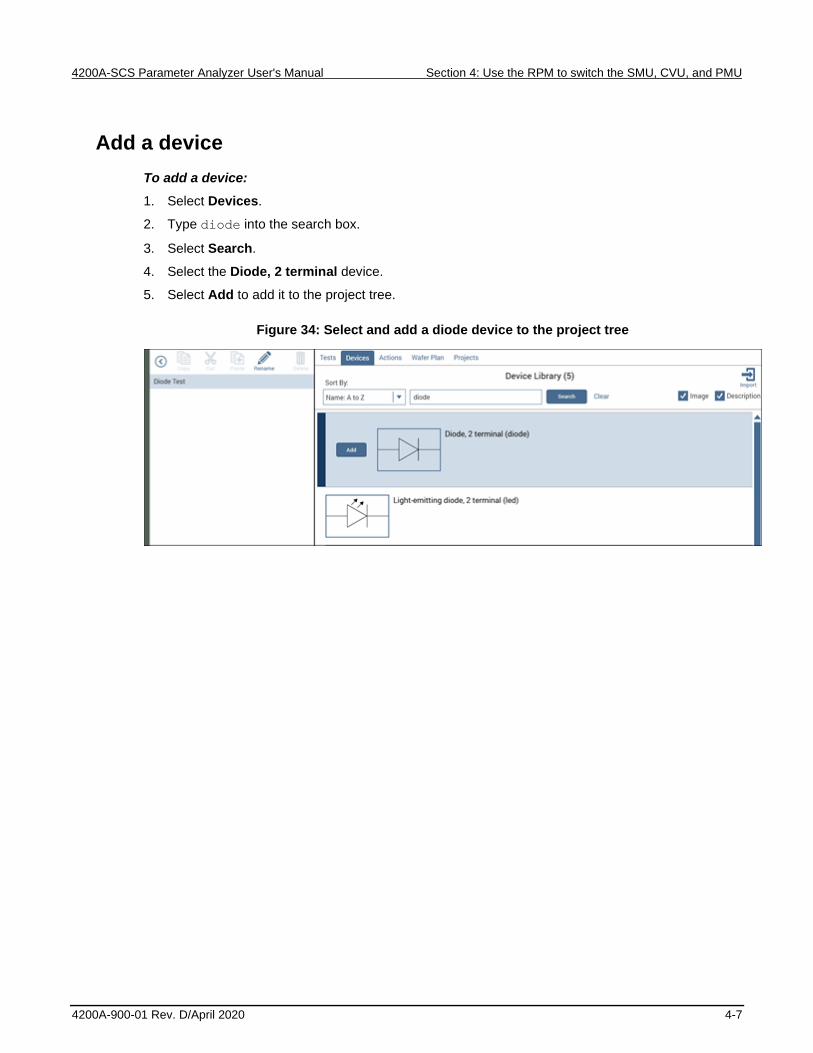
Add a device
To add a device:
1. Select Devices.
2. Type diode into the search box.
3. Select Search.
4. Select the Diode, 2 terminal device.
5. Select Add to add it to the project tree.
Figure 34: Select and add a diode device to the project tree

Section 4: Use the RPM to switch the SMU, CVU, and PMU 4200A-SCS Parameter Analyzer User's Manual
4-8 4200A-900-01 Rev. D/April 2020
Search for and select existing tests in the Test Library
To search for and select an existing test:
1. Select Tests.
2. To find a diode test in the Test Library, type the word diode in the search box, then select
Search.
3. Scroll to find the Diode Forward I-V Sweep (vfd) test.
4. Select Add to add the test to the project tree.
Figure 35: Add the Diode Forward I-V Sweep (vfd) test to the project tree
5. Scroll to find the Diode C-V Sweep (cv-diode) test.
6. Select Add to add this test to the project tree.
Figure 36: Diode C-V Sweep (cv-diode) test
7. Scroll to find the Diode Pulse I-V Sweep (pulse-diode) test.
8. Select Add to add this test to the project tree.
Figure 37: Diode Pulse I-V Sweep (pulse-diode) test

4200A-SCS Parameter Analyzer User's Manual Section 4: Use the RPM to switch the SMU, CVU, and PMU
4200A-900-01 Rev. D/April 2020 4-9
Your project tree now has three tests.
Figure 38: Three tests added to project tree
Configure the vfd test
To configure the vfd test:
1. Choose Configure.
Figure 39: Configure highlighted

Section 4: Use the RPM to switch the SMU, CVU, and PMU 4200A-SCS Parameter Analyzer User's Manual
4-10 4200A-900-01 Rev. D/April 2020
2. In the project tree, select the vfd test.
3. Adjust the Anode settings in the Key Parameters pane as needed.
Figure 40: Forward I-V sweep, vfd terminal settings
4. In the Test Settings pane, select Advanced.
5. Adjust the parameters as needed. Be sure to include the delay between sweep steps.
Figure 41: Test Settings pane and Test Settings Advanced dialog box

4200A-SCS Parameter Analyzer User's Manual Section 4: Use the RPM to switch the SMU, CVU, and PMU
4200A-900-01 Rev. D/April 2020 4-11
6. Select OK to accept the settings.
7. Select Terminal Settings.
8. Select Advanced.
9. Adjust the voltage source and current measurement parameters as needed.
Figure 42: Terminal Settings pane and Terminal Settings Advanced dialog box
10. Select OK to accept the changes.

Section 4: Use the RPM to switch the SMU, CVU, and PMU 4200A-SCS Parameter Analyzer User's Manual
4-12 4200A-900-01 Rev. D/April 2020
Configure the cv-diode test
To configure the cv-diode test:
1. Select the cv-diode test from the project tree.
2. Select the Anode terminal of the diode in the Key Parameters pane
3. Adjust the voltage source and test frequency settings as needed.
Figure 43: Key Parameters pane for the cv-diode sweep test

4200A-SCS Parameter Analyzer User's Manual Section 4: Use the RPM to switch the SMU, CVU, and PMU
4200A-900-01 Rev. D/April 2020 4-13
4. On the Test Settings pane, select Advanced. Adjust the timing parameters as needed. Be sure to
include the sweep delay time in your adjustments.
Figure 44: Test Settings pane and the Test Settings Advanced and Formulator dialog boxes for
the cv-diode sweep test

Section 4: Use the RPM to switch the SMU, CVU, and PMU 4200A-SCS Parameter Analyzer User's Manual
4-14 4200A-900-01 Rev. D/April 2020
5. On the Terminal Settings pane and the Terminal Settings Advanced dialog box of the Anode
terminal, adjust the parameters.
If you are including cable compensation values, run the Tools menu option CVU Connection
Compensation. Refer to Perform offset compensation (on page 7-10) for more detail.
Figure 45: Terminal Settings pane and the Terminal Settings Advanced dialog box for the
cv-diode sweep test
4200A-SCS Parameter Analyzer User's Manual Section 4: Use the RPM to switch the SMU, CVU, and PMU
4200A-900-01 Rev. D/April 2020 4-15
Configure the pulse-diode test
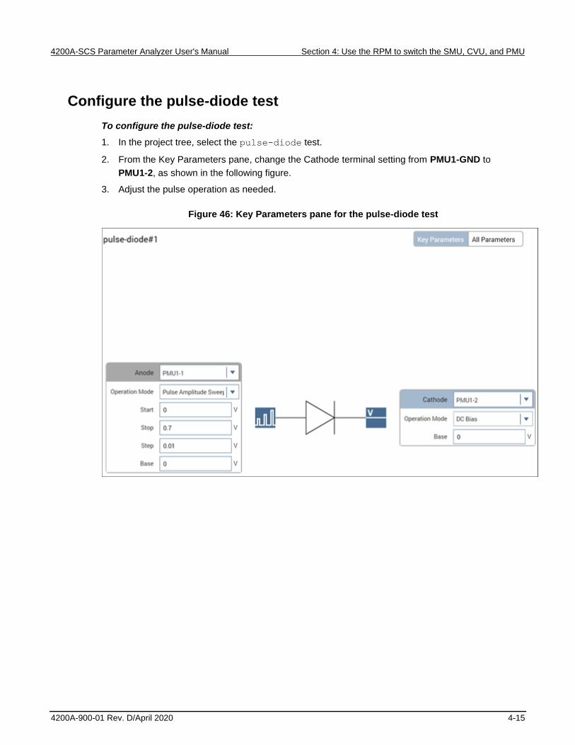
To configure the pulse-diode test:
1. In the project tree, select the pulse-diode test.
2. From the Key Parameters pane, change the Cathode terminal setting from PMU1-GND to
PMU1-2, as shown in the following figure.
3. Adjust the pulse operation as needed.
Figure 46: Key Parameters pane for the pulse-diode test

Section 4: Use the RPM to switch the SMU, CVU, and PMU 4200A-SCS Parameter Analyzer User's Manual
4-16 4200A-900-01 Rev. D/April 2020
4. Select the Anode terminal.
5. Select Terminal Settings.
6. Select Advanced to configure the measurements as needed, including spot mean, PMU
compensation, and PMU threshold levels.
Figure 47: Terminal Settings pane and the Terminal Settings Advanced dialog box for
Pulse-Diode test

4200A-SCS Parameter Analyzer User's Manual Section 4: Use the RPM to switch the SMU, CVU, and PMU
4200A-900-01 Rev. D/April 2020 4-17
7. Select OK.
8. Select the Cathode terminal.
9. Select Test Settings.
10. Select Advanced to adjust the test mode and pulse timing settings, as needed.
Figure 48: Test Settings pane and the Test Settings Advanced dialog box for the Pulse-Diode
test
11. Select OK to accept the changes.

Section 4: Use the RPM to switch the SMU, CVU, and PMU 4200A-SCS Parameter Analyzer User's Manual
4-18 4200A-900-01 Rev. D/April 2020
Run the test
Once the tests have been configured, you can execute every test under the device.
To run the tests for the device:
1. Select the diode device in the project tree.
2. Verify that the check boxes for the tests and the device are selected.
3. Select Run. The three tests run sequentially and the RPM automatically switches the outputs
between the SMU, CVU, and PMU.
4. Select the Analyze pane to see the results.
As the instruments switch between tests, the LEDs at the top of the RPMs change color. When the
output is connected to the SMU, the LED is blue. When the output is connected to the CVU, the LED
is red. When the output is connected to the PMU, the LED is green, which is also the default state.
Figure 49: Top of the 4225-RPM indicating the LED status
View and analyze the test results
You can select Analyze when you run the project to view test results in real-time.
Figure 50: Analyze highlighted

4200A-SCS Parameter Analyzer User's Manual Section 4: Use the RPM to switch the SMU, CVU, and PMU
4200A-900-01 Rev. D/April 2020 4-19
Select a test from the project tree to display its results. The data for the vfd test is displayed in the
next figure. Both the data and the graph are displayed in this view.
Figure 51: Analyze pane for the vfd test


In this section:
Introduction .............................................................................. 5-1 Equipment required .................................................................. 5-2 Device connections .................................................................. 5-2 Update the switch configuration in KCon ................................. 5-6 Set up the measurements in Clarius ...................................... 5-11
Introduction
In this tutorial, you will configure a Keithley Instruments Series 700 Switching System (707, 707A,
707B, 708, 708A, or 708B) in the Keithley Configuration Utility (KCon). You will then use the system
to connect any instrument terminal to any test system pin without changing connections. You will also
create a new project for an n-channel MOSFET transistor and use the project to make both I-V and
C-V measurements using the switching system.
Switching systems are controlled by the 4200A-SCS using the GPIB bus. Use a 7007-1 or 7007-2
GPIB cable to connect your switching system to the 4200A-SCS. Once the switching system and test
fixture have been defined in KCon, you use Clarius to set up the connections and automatically
connect the instruments to the test system pins using the switching system.
In Clarius, the connectpins action from the Action Library is used to control switching systems. This
action controls the opening and closing of crosspoints in a switching system so that you can connect
any row of the matrix card to any (or multiple) columns of the matrix card. The connectpins action
is added to the project and runs twice in this example. Each run establishes new connection settings.
For more details about switching system connections and the Action Library, refer to the Model
4200A-SCS Reference Manual.
Section 5
Configure and use a Series 700 Switching System
Section 5: Configure and use a Series 700 Switching System 4200A-SCS Parameter Analyzer User's Manual
5-2 4200A-900-01 Rev. D/April 2020
Equipment required
• One 4200A-SCS with the following instruments:
▪ Three 420x-SMUs or 421x-SMUs
▪ One 421x-CVU
• Eight 4200-MTRX-X triaxial cables or 4200-TRX-X cables if using preamplifiers
• Four CA-447A SMA cables (supplied with the CVU)
• Four CS-1247 SMA female to BNC male adapters (supplied with the CVU)
• Two CS-701A BNC Tee adapters (female, male, female)
• Two 7078-TRX-BNC BNC female to triaxial male adapters
• One Series 700 Switching System with a 7072 8x12 Matrix Card
• One shielded four-terminal test fixture with triaxial inputs
• One n-channel MOSFET transistor
Device connections
The next topics detail the connections from the 7072 to the n-channel MOSFET and the connections
from the SMUs or CVU, and GNDU to the 7072 Matrix Card in the Series 700 Switching System.
Hazardous voltages may be present on all output and guard terminals. To prevent electrical
shock that could cause injury or death, never connect or disconnect from the 4200A-SCS
while the output is on.
To prevent electric shock, test connections must be configured such that the user cannot
come in contact with test leads, conductors, or any device under test (DUT) that is in contact
with the conductors. It is good practice to disconnect DUTs from the instrument before
powering up the instrument. Safe installation requires proper shields, barriers, and grounding
to prevent contact with test lead and conductors.
4200A-SCS Parameter Analyzer User's Manual Section 5: Configure and use a Series 700 Switching System
4200A-900-01 Rev. D/April 2020 5-3
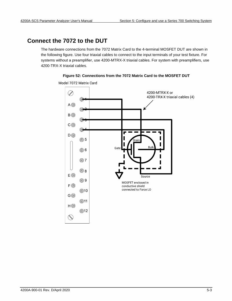
Connect the 7072 to the DUT
The hardware connections from the 7072 Matrix Card to the 4-terminal MOSFET DUT are shown in
the following figure. Use four triaxial cables to connect to the input terminals of your test fixture. For
systems without a preamplifier, use 4200-MTRX-X triaxial cables. For system with preamplifiers, use
4200-TRX-X triaxial cables.
Figure 52: Connections from the 7072 Matrix Card to the MOSFET DUT
Section 5: Configure and use a Series 700 Switching System 4200A-SCS Parameter Analyzer User's Manual
5-4 4200A-900-01 Rev. D/April 2020
Connect the 4200A-SCS to the 7072
This section describes connections to the 7072.
To connect the 4200A-SCS and SMUs to the 7072:
Using four 4200-MTRX-X or 4200-TRX-X triaxial cables, make the following connections:
• 4200A-SCS GNDU FORCE to 7072 input terminal E
• 42x0 SMU channel 1 Force to 7072 input terminal A
• 42x0 SMU channel 2 Force to 7072 input terminal B
• 42x0 SMU channel 3 Force to 7072 input terminal C
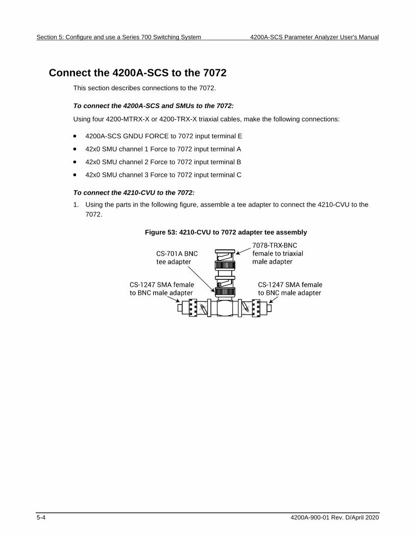
To connect the 4210-CVU to the 7072:
1. Using the parts in the following figure, assemble a tee adapter to connect the 4210-CVU to the
7072.
Figure 53: 4210-CVU to 7072 adapter tee assembly

4200A-SCS Parameter Analyzer User's Manual Section 5: Configure and use a Series 700 Switching System
4200A-900-01 Rev. D/April 2020 5-5
2. Using four CA-447A SMA cables, make the following connections:
▪ 4210-CVU HCUR to adapter tee assembly 1
▪ 4210-CVU HPOT to adapter tee assembly 1
▪ 4210-CVU LPOT to adapter tee assembly 2
▪ 4210-CVU LCUR to adapter tee assembly 2
3. Connect adapter tee assembly 1 to input terminal G of the 7072.
4. Connect adapter tee assembly 2 to input terminal H of the 7072.
The connections are shown in the following figure.
Figure 54: 4200A-SCS to 7072 Matrix Card connections

Section 5: Configure and use a Series 700 Switching System 4200A-SCS Parameter Analyzer User's Manual
5-6 4200A-900-01 Rev. D/April 2020
Update the switch configuration in KCon
After completing the switch and device connections, use KCon to manage the configuration of all
instrumentation controlled by the 4200A-SCS software. You use KCon to:
• Add the switching system to the 4200A-SCS configuration
• Add the test fixture to the system configuration
• Configure the test fixture
• Add a matrix card to the switching system
• Configure the matrix card connections
To add a switching system to the 4200A-SCS configuration:
1. From the desktop, open the KCon application.
2. In the bottom left of the KCon window, select Add External Instrument.
3. Select your switching system. The Series 700 Switching Systems are highlighted in the next
figure.
Figure 55: Add External Instrument box, Series 700 Switching Systems highlighted

4200A-SCS Parameter Analyzer User's Manual Section 5: Configure and use a Series 700 Switching System
4200A-900-01 Rev. D/April 2020 5-7
4. Select OK.
5. Select Add External Instrument again.
6. Select Test Fixture.
Figure 56: Add External Instrument dialog box, Test Fixture highlighted
7. Select OK.
8. From the configuration navigator, select the test fixture you just added (TF1).
9. Set the number of pins equal to the number of output pins in your switching system (12 for this
example, using one 7072 matrix card).
Figure 57: Properties for a Generic Test Fixture

Section 5: Configure and use a Series 700 Switching System 4200A-SCS Parameter Analyzer User's Manual
5-8 4200A-900-01 Rev. D/April 2020
10. From the configuration navigator, select the switching system you just added (MTRX1).
11. In the Properties pane, add the 7072 Matrix Card to the correct slot of the switching system.
12. Confirm that the GPIB Channel of your device (0 to 30) matches the channel shown in the
Properties. The next figure shows a Keithley Instruments 707/707A/707B Switching System with
the matrix card installed in slot 1.
Figure 58: Properties pane of Keithley 708/708A/708B Switching System with one 7072 Matrix
Card
If you are using a 707B or 708B Switching System, you must use the control panel on the front of
your switching system to enable DDC and change the command set to 70XA by following these
steps:
1. Select Menu.
2. Select DDC.
3. Select Enable.
4. Select 70XB-VERSION.
This allows the switching system to be controlled by the 4200A-SCS.

4200A-SCS Parameter Analyzer User's Manual Section 5: Configure and use a Series 700 Switching System
4200A-900-01 Rev. D/April 2020 5-9
13. Select the arrow next to MTRX1 to see the settings for the 7072 Matrix Card.
14. Select CARD1.
15. Complete the Card Rows Assignments according to how you connected the instruments to the
7072. For this example, the assignments are:
▪ Row A - SMU1 Force
▪ Row B - SMU2 Force
▪ Row C - SMU3 Force
▪ Row E - GNDU Force
▪ Row G - CVU1 CVH_CUR
▪ Row H - CVU1 CVL_CUR
16. Under the Card Columns Assignment heading, designate at least the first four columns with pin
assignments that match their column number. For example, Pin 1 Force to column 1.
Figure 59: Completed Properties pane for the 7072 Matrix Card
17. From the KCon toolbar, select Validate Configuration to ensure that the switching system is
connected properly.
Figure 60: Validate Configuration icon

Section 5: Configure and use a Series 700 Switching System 4200A-SCS Parameter Analyzer User's Manual
5-10 4200A-900-01 Rev. D/April 2020
18. Select Save to save the system configuration.
19. Select System Configuration Summary, then scroll down to the Connections section. You need
the names from the Terminal ID column when setting the switching system connections in Clarius.
You can select Save Configuration As or Print Configuration to record the terminal IDs. The
default values for the most common instruments are shown in the next figure.
Figure 61: System Configuration Summary: Default Terminal ID Connections
20. Close the window when you are finished.
21. Close the KCon application.

4200A-SCS Parameter Analyzer User's Manual Section 5: Configure and use a Series 700 Switching System
4200A-900-01 Rev. D/April 2020 5-11
Set up the measurements in Clarius
After closing KCon, open the Clarius application from the desktop. In this section, you use the Clarius
application to configure and run two tests on an n-channel MOSFET transistor: A plot of drain current
versus drain voltage using the SMUs and a C-V sweep. By using the Series 700 Switching System,
you do not need to rearrange cables between the tests.
For this example, you use the Clarius application to:
• Create a new project
• Add a device
• Add an action
• Configure the action
• Search for and add two tests
• Run the project and view the tests
Create a new project
To create a new project:
1. Choose Select.
Figure 62: Select highlighted
2. In the Library, select Projects.
3. Select New Project.
4. Select Create.
Figure 63: Select a New Project from the Project Library

Section 5: Configure and use a Series 700 Switching System 4200A-SCS Parameter Analyzer User's Manual
5-12 4200A-900-01 Rev. D/April 2020
5. Select Yes when prompted to replace the existing project.
Add a device
To add a device:
1. Select Devices.
2. Enter MOSFET in the search box.
3. Select Search.
4. Scroll to the MOSFET, n-type, 4 terminal (4terminal-n-fet) device.
5. Select Add to add it to the project tree.
Add the connectpins action
To add the connectpins action:
1. Select Actions.
2. Type connect in the search box.
3. Select Search.
4. Scroll to the connectpins action, then Add it to the project tree twice.
Figure 64: connectpins added twice

4200A-SCS Parameter Analyzer User's Manual Section 5: Configure and use a Series 700 Switching System
4200A-900-01 Rev. D/April 2020 5-13
Configure the connectpins action
To configure the connectpins action:
1. Select the first connectpins action you added to the project tree.
2. Select Configure.
Figure 65: Configure highlighted

Section 5: Configure and use a Series 700 Switching System 4200A-SCS Parameter Analyzer User's Manual
5-14 4200A-900-01 Rev. D/April 2020
3. Make the following connections using the pairs of TermIdStr# and Pin# fields in the action:
▪ SMU1 – Pin 3
▪ SMU2 – Pin 2
▪ SMU3 – Pin 1
▪ GNDU – Pin 4
When you are finished, the Key Parameters view of the action should look like the next graphic. The
order of the instruments does not matter if each instrument is paired with the correct pin number.
In this example, assigning TermIdStr1 to SMU1 and Pin 1 to 3 connects SMU1 to Pin 3 on the matrix.
Figure 66: connectpins device connections
If the OpenAll check box is selected, the connectpins action opens all crosspoints before closing
the specified pairs. This is the default and is usually the preferred behavior. However, since
connectpins only has eight field pairs, the action can only close eight crosspoints during each run.
To close more crosspoints, use multiple connectpins actions.

4200A-SCS Parameter Analyzer User's Manual Section 5: Configure and use a Series 700 Switching System
4200A-900-01 Rev. D/April 2020 5-15
4. Select Save.
5. Select the second connectpins action you added to the project tree.
6. Make the following connections using the pairs of TermIdStr# and Pin# text fields in the action:
▪ CVH1 – Pin 1
▪ CVL1 – Pin 2
▪ CVL1 – Pin 3
▪ CVL1 – Pin 4
When you are finished, the Key Parameters for the action look like the next figure.
Figure 67: Second connectpins connections
7. Select Save.

Section 5: Configure and use a Series 700 Switching System 4200A-SCS Parameter Analyzer User's Manual
5-16 4200A-900-01 Rev. D/April 2020
Search for and add existing tests from the Test Library
To search for and add existing tests from the Test Library:
1. Choose Select.
Figure 68: Select highlighted
2. Select Tests.
3. Type vds into the search box.
4. Select Search.
5. Scroll to the vds-id test.
6. Select Add to add it to the project tree.
7. Drag the vds-id test to between the two connectpins actions.
8. Clear the search box.
9. Type cv into the search box.
10. Select Search.
11. Scroll to the cv-nmosfet test. Select Add to add it to the project tree.
12. Drag the cv-nmosfet test after the second connectpins action.
Your project tree looks like the next figure.
Figure 69: Project tree showing tests and actions in the proper order

4200A-SCS Parameter Analyzer User's Manual Section 5: Configure and use a Series 700 Switching System
4200A-900-01 Rev. D/April 2020 5-17
Run the project and view the tests
To run the project and view the tests:
1. In the project tree, select New Project.
2. Make sure the items in the project tree are checked.
3. Select Run to start the test. The two actions and tests run sequentially. The connectpins
actions set the crosspoints before the tests are executed.
You can select Analyze when you run the project to view test results in real-time.
Figure 70: Analyze highlighted
To view the results of a test either as it runs or after it has completed, select the test in the project
tree.


In this section:
Introduction .............................................................................. 6-1 Equipment required .................................................................. 6-1 Device connections .................................................................. 6-2 Setting up measurements in the Clarius software .................... 6-4
Introduction
This example shows how to use a 420x-SMU or 421x-SMU instrument to perform a forward-biased
voltage sweep on a solar cell in a 4-wire configuration. Current is measured on each step of the
sweep and an I-V graph is generated from the collected data. The Formulator calculates common
electrical characteristics of the cell.
These instructions show you how to make connections from the SMU to the solar cell and how to add
the forward bias I-V test into a new project and automate the measurements.
From the I-V characteristics measured by the 4200A-SCS, you can determine important parameters
about the solar cell, including:
• Maximum current (Imax) and voltage (Vmax)
• Maximum power (Pmax)
• Open-circuit voltage (Voc)
• Short-circuit current (Isc)
Equipment required
• One 4200A-SCS with one 420x-SMU or one 421x-SMU
• Four triaxial cables (4200-TRX-2 or 4200-MTRX-2)
• One solar cell
• One light source
Section 6
Make I-V measurements on a solar cell

Section 6: Make I-V measurements on a solar cell 4200A-SCS Parameter Analyzer User's Manual
6-2 4200A-900-01 Rev. D/April 2020
Device connections
Connect your preamplifier or SMU output terminals to the solar cell in a 4-wire configuration. This
provides the best measurement accuracy and eliminates the effects of the resistance of the test leads
and unwanted voltage drops.
Hazardous voltages may be present on all output and guard terminals. To prevent electrical
shock that could cause injury or death, never connect or disconnect from the 4200A-SCS
while the output is on.
To prevent electric shock, test connections must be configured such that the user cannot
come in contact with test leads, conductors, or any device under test (DUT) that is in contact
with the conductors. It is good practice to disconnect DUTs from the instrument before
powering up the instrument. Safe installation requires proper shields, barriers, and grounding
to prevent contact with test lead and conductors.
Device connection schematic
Connections to the solar cell can be made using two SMUs or one SMU and the Ground Unit (GNDU).
The next figure shows the connection schematic for the application.
Figure 71: Solar cell device connection schematic
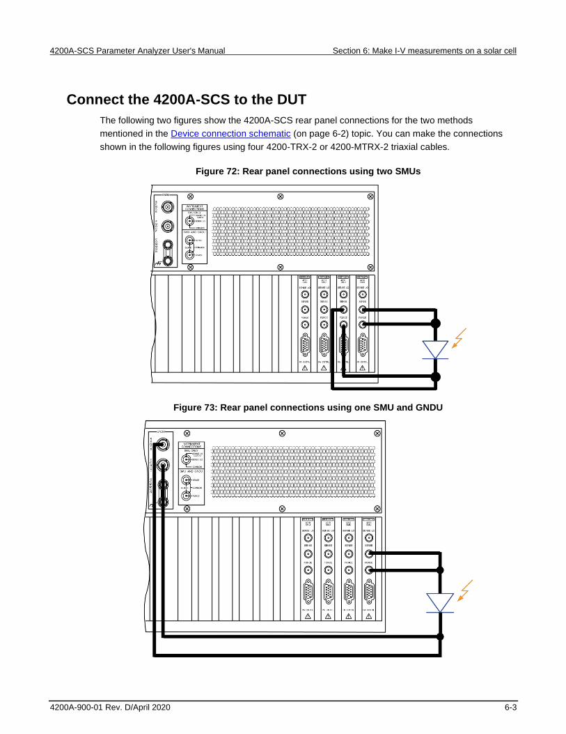
4200A-SCS Parameter Analyzer User's Manual Section 6: Make I-V measurements on a solar cell
4200A-900-01 Rev. D/April 2020 6-3
Connect the 4200A-SCS to the DUT
The following two figures show the 4200A-SCS rear panel connections for the two methods
mentioned in the Device connection schematic (on page 6-2) topic. You can make the connections
shown in the following figures using four 4200-TRX-2 or 4200-MTRX-2 triaxial cables.
Figure 72: Rear panel connections using two SMUs
Figure 73: Rear panel connections using one SMU and GNDU
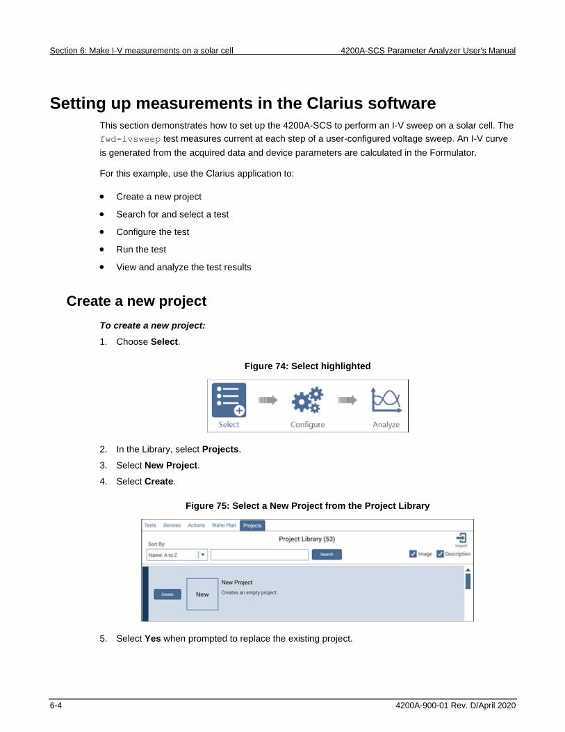
Section 6: Make I-V measurements on a solar cell 4200A-SCS Parameter Analyzer User's Manual
6-4 4200A-900-01 Rev. D/April 2020
Setting up measurements in the Clarius software
This section demonstrates how to set up the 4200A-SCS to perform an I-V sweep on a solar cell. The
fwd-ivsweep test measures current at each step of a user-configured voltage sweep. An I-V curve
is generated from the acquired data and device parameters are calculated in the Formulator.
For this example, use the Clarius application to:
• Create a new project
• Search for and select a test
• Configure the test
• Run the test
• View and analyze the test results
Create a new project
To create a new project:
1. Choose Select.
Figure 74: Select highlighted
2. In the Library, select Projects.
3. Select New Project.
4. Select Create.
Figure 75: Select a New Project from the Project Library
5. Select Yes when prompted to replace the existing project.

4200A-SCS Parameter Analyzer User's Manual Section 6: Make I-V measurements on a solar cell
4200A-900-01 Rev. D/April 2020 6-5
Search for and select a test
To search for and select the test:
1. Select Tests.
2. In the Filters pane, select Solar Cell.
Figure 76: Use filters to select the fwd-ivsweep test
3. Select the Solar Cell Forward I-V Sweep (fwd-ivsweep) test.
4. Select Add.
The test is displayed in the project tree.
Figure 77: Test added to the project tree

Section 6: Make I-V measurements on a solar cell 4200A-SCS Parameter Analyzer User's Manual
6-6 4200A-900-01 Rev. D/April 2020
Configure the test
To configure the test:
1. Select the fwd-ivsweep solar cell I-V test in the project tree.
2. Select Configure.
Figure 78: Configure highlighted
3. Adjust the Anode settings as needed.
Figure 79: Key Parameters pane for the I-V sweep of a solar cell

4200A-SCS Parameter Analyzer User's Manual Section 6: Make I-V measurements on a solar cell
4200A-900-01 Rev. D/April 2020 6-7
4. In the Test Settings pane, adjust the Measure Settings and Test Mode as needed.
Figure 80: Test Settings pane
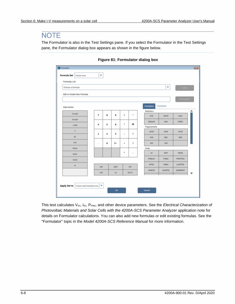
Section 6: Make I-V measurements on a solar cell 4200A-SCS Parameter Analyzer User's Manual
6-8 4200A-900-01 Rev. D/April 2020
The Formulator is also in the Test Settings pane. If you select the Formulator in the Test Settings
pane, the Formulator dialog box appears as shown in the figure below.
Figure 81: Formulator dialog box
This test calculates Voc, Isc, Pmax, and other device parameters. See the Electrical Characterization of
Photovoltaic Materials and Solar Cells with the 4200A-SCS Parameter Analyzer application note for
details on Formulator calculations. You can also add new formulas or edit existing formulas. See the
"Formulator" topic in the Model 4200A-SCS Reference Manual for more information.

4200A-SCS Parameter Analyzer User's Manual Section 6: Make I-V measurements on a solar cell
4200A-900-01 Rev. D/April 2020 6-9
Run the test
1. Highlight the fwd-ivsweep test in the project tree.
2. Select Run to execute the test.
Figure 82: Run
Analyze the test results
You can select Analyze when you run the project to view test results in real-time.
Figure 83: Analyze highlighted
You can also use the View icons in the upper-right of the center pane to display the sheet, graph, or
sheet and graph. The sheet only view is shown in the next figure.
Figure 84: Sheet only view selected, View icons highlighted

Section 6: Make I-V measurements on a solar cell 4200A-SCS Parameter Analyzer User's Manual
6-10 4200A-900-01 Rev. D/April 2020
The sheet displays the results with the voltage and current data labeled Anode V and Anode I,
respectively. The formulas calculated in the Formulator are shown in the right-most columns. They
include the maximum power (PMAX), open circuit voltage (VOC), short circuit current (ISC), and fill
factor (FF). More information about the sheet and Formulator can be found in the Model 4200A-SCS
Reference Manual.
To see an expanded view of the graphed test results, select the graph view. The following graph
shows the sweep of an illuminated silicon photovoltaic (PV) cell generated by the SMU.
Figure 85: Test results showing I-V graph of an illuminated solar cell
Because the system SMUs can sink current, the curve can pass through the fourth quadrant and
allow power to be extracted from the device (I–, V+). If you want to have the data displayed in the first
quadrant, use the Formulator to multiply the current by -1 and plot this calculated result instead.
You can also show previous test runs in the graph window by selecting them under the Run History
tab. Select the check box next to the test you want to display, and the test curves are displayed in the
graph window. If you select multiple run histories, the graphs are overlaid.
Additional tests
You can add other solar cell tests to the project. Search for solar cell in the Tests library to find
additional tests.

In this section:
Introduction .............................................................................. 7-1 Equipment required .................................................................. 7-1 Device connections .................................................................. 7-2 Set up the measurements in Clarius ........................................ 7-4
Introduction
Capacitance-voltage (C-V) measurements are commonly used to study gate-oxide quality in detail.
These measurements are made on two-terminal devices called MOS capacitors, which are MOSFETs
without a source and drain. C-V test results offer device and process information, including bulk and
interface charges. Many MOS device parameters, such as oxide thickness, flat band voltage, and
threshold voltage, can also be extracted from the C-V test data.
This section provides an example of how to use the 4210-CVU C-V Analyzer to make a C-V sweep
on a MOS capacitor and derive common parameter extractions from the C-V data using the
Formulator.
Equipment required
One 4200A-SCS with the following instruments and accessories:
• One 421x-CVU
• Four CA-447A SMA cables
• Four CS-1247 SMA female to BNC male adapters
• Two CS-701 BNC tee adapters
Section 7
Make C-V measurements on a MOSCAP

Section 7: Make C-V measurements on a MOSCAP 4200A-SCS Parameter Analyzer User's Manual
7-2 4200A-900-01 Rev. D/April 2020
Device connections
Using the supplied cables, make connections from the output terminals of the CVU to the MOS
capacitor.
Hazardous voltages may be present on all output and guard terminals. To prevent electrical
shock that could cause injury or death, never connect or disconnect from the 4200A-SCS
while the output is on.
To prevent electric shock, test connections must be configured such that the user cannot
come in contact with test leads, conductors, or any device under test (DUT) that is in contact
with the conductors. It is good practice to disconnect DUTs from the instrument before
powering up the instrument. Safe installation requires proper shields, barriers, and grounding
to prevent contact with test lead and conductors.

4200A-SCS Parameter Analyzer User's Manual Section 7: Make C-V measurements on a MOSCAP
4200A-900-01 Rev. D/April 2020 7-3
Connect the 4200A-SCS to the DUT
The hardware connections from the output terminals of the CVU to the MOS capacitor are shown in
the following figure. Connect one cable to each of the CVU terminals, then connect one SMA female
to BNC male adapter to the end of each cable.
The cables from the HCUR and HPOT terminals are coupled with the BNC tee adapter and are then
connected to the gate of the MOS capacitor. The cables from the LCUR and LPOT terminals are also
connected together with the BNC tee adapter and then are connected to the bulk of the MOS
capacitor.
In the Clarius application, you will configure HCUR to be the high terminal of the AC ammeter and
HPOT to be the high of the DC voltage source.
Figure 86: Connections from the 4210-CVU to the MOS capacitor

Section 7: Make C-V measurements on a MOSCAP 4200A-SCS Parameter Analyzer User's Manual
7-4 4200A-900-01 Rev. D/April 2020
Set up the measurements in Clarius
This section describes how to set up the Clarius application to make a C-V sweep on a MOS
capacitor. You select an existing project from the project library and configure a C-V sweep test.
For this example, you will use Clarius to:
• Search for and select a project in the Project Library
• Configure the test
• Perform offset compensation
• Run the test
• View and analyze the test results
Search for and select a project
1. Choose Select.
Figure 87: Select highlighted

4200A-SCS Parameter Analyzer User's Manual Section 7: Make C-V measurements on a MOSCAP
4200A-900-01 Rev. D/April 2020 7-5
2. Select Projects.
3. Type MOScap into the search bar.
4. Select Search.
5. Select MOS Capacitor C-V project (cvu-moscap).
6. Select Create.
7. Select Yes when prompted to replace the existing project.
The project is displayed. This project has three C-V tests for a MOS capacitor, as shown in the next
figure.
Figure 88: MOS capacitor C-V project tree with three tests
Configure the test
To configure the C-V sweep test, you set the source and measure parameters, define the timing
parameters, and adjust the constants and formulas for extracting parameters from the C-V data.
This test makes a capacitance measurement at each step of a user-configured voltage sweep. A C-V
graph is generated from the acquired data and several device parameters are calculated in the
Formulator.
To configure the test:
1. Select Configure.
Figure 89: Configure highlighted

Section 7: Make C-V measurements on a MOSCAP 4200A-SCS Parameter Analyzer User's Manual
7-6 4200A-900-01 Rev. D/April 2020
2. In the project tree, select the moscap-cvsweep test.
3. In the Key Parameters pane, adjust the voltage sweep and test frequency values as needed.
Figure 90: Key parameters for the C-V sweep of a MOS capacitor

4200A-SCS Parameter Analyzer User's Manual Section 7: Make C-V measurements on a MOSCAP
4200A-900-01 Rev. D/April 2020 7-7
4. In the Test Settings pane, set the Speed to Quiet for sensitive capacitance measurements.
Figure 91: Test Settings pane

Section 7: Make C-V measurements on a MOSCAP 4200A-SCS Parameter Analyzer User's Manual
7-8 4200A-900-01 Rev. D/April 2020
5. Adjust the Sweep Delay as needed.
6. Select Formulator. In this test, the Formulator contains equations for deriving common MOS
capacitor parameters from the C-V data. Examples of these parameters include the oxide
capacitance, oxide thickness, flatband voltage, flatband capacitance, threshold voltage, and
doping concentration. You can view, edit, and add equations in this dialog box.
Figure 92: Formulator dialog box

4200A-SCS Parameter Analyzer User's Manual Section 7: Make C-V measurements on a MOSCAP
4200A-900-01 Rev. D/April 2020 7-9
The next figure shows some of the equations that are included with this test. In the Constants
area of the Formulator, you can change the constants that are used in the formulas, such as the
gate area and temperature.
Figure 93: Formulas listed in the Formulator
7. Select OK to accept changes made in the Formulator.
8. From the Terminal Settings Advanced dialog box, adjust the parameters as needed.
Figure 94: Terminal Settings pane and Terminal Settings Advanced dialog box

Section 7: Make C-V measurements on a MOSCAP 4200A-SCS Parameter Analyzer User's Manual
7-10 4200A-900-01 Rev. D/April 2020
In this test, the CVH1 terminals are internally connected to the AC ammeter and the HI of the DC
voltage source by default. The CVH1 terminals are externally connected to the gate of the MOS
capacitor. The CVL1 terminals are internally connected to the AC voltage source and the LO of the
DC voltage source and are externally connected to the bulk of the MOS capacitor or to the prober
chuck.
Perform offset compensation
C-V measurements on a MOS capacitor are generally performed on a wafer using a prober. The
4210-CVU is connected to the MOS capacitor through cables, adapters, and a prober. Cabling adds
stray capacitance to measurements.
To correct for the stray capacitance, Clarius has tools for offset correction. Correction is a two-part
process: You perform the corrections for open, and then you enable the corrections in the Terminal
Settings pane.
Open compensation is generally used for high impedance measurements (<10 pF or >1 MΩ). A short
compensation correction is generally used for low impedance measurements (>10 nF or <10 Ω). For
a short compensation, you select Measure Short, and then short the probe to the chuck.
To perform the corrections:
1. Select Tools.
Figure 95: Tools icon in Clarius

4200A-SCS Parameter Analyzer User's Manual Section 7: Make C-V measurements on a MOSCAP
4200A-900-01 Rev. D/April 2020 7-11
2. Select CVU Connection Compensation from the Clarius Tools dialog box.
Figure 96: Clarius Tools dialog box
3. Disconnect the probes from the DUT.
4. Select Measure Open.
Figure 97: CVU Connection Compensation dialog box

Section 7: Make C-V measurements on a MOSCAP 4200A-SCS Parameter Analyzer User's Manual
7-12 4200A-900-01 Rev. D/April 2020
5. Select OK. You are prompted to verify that the probes have been disconnected from the DUT.
Figure 98: Prompt to remove probes from DUT

4200A-SCS Parameter Analyzer User's Manual Section 7: Make C-V measurements on a MOSCAP
4200A-900-01 Rev. D/April 2020 7-13
6. Make sure that the probes have been disconnected from the DUT, then select OK. The
compensation runs, and a dialog box confirms that the compensation has run successfully.
7. Select Exit to close the Tools dialog box.
8. From the Terminal Settings pane, enable corrections by selecting the Open checkbox.
Figure 99: Enabling CVU Compensation

Section 7: Make C-V measurements on a MOSCAP 4200A-SCS Parameter Analyzer User's Manual
7-14 4200A-900-01 Rev. D/April 2020
Run the test
Select Run to execute the test.
Figure 100: Run
View and analyze the test results
Select Analyze when you run the project to view test results in real-time.
Figure 101: Analyze highlighted
The C-V data is plotted on the graph as the moscap-cvsweep test executes.
Figure 102: Graph in the Analyze pane

4200A-SCS Parameter Analyzer User's Manual Section 7: Make C-V measurements on a MOSCAP
4200A-900-01 Rev. D/April 2020 7-15
You can also click the data only view of the Analyze sheet, as highlighted in the next figure, to display
more data. For example, you can display a holistic view of the parameters for a device.
Figure 103: C-V data in the sheet


In this section:
Introduction .............................................................................. 8-1 Equipment required .................................................................. 8-2 Device connections .................................................................. 8-2 Set up the measurements in Clarius ........................................ 8-4
Introduction
This section shows you how to use the 4200A-SCS and Model 4200A-CVIV Multi-Switch to perform
I-V and C-V measurements on the same device without having to manually change connections to
the device between tests.
The 4200A-CVIV allows you to switch between I-V and C-V measurements and make C-V
measurements between output terminals of the 4200A-CVIV.
The 4200A-CVIV can be equipped with up to four 4200-PA Remote Preamplifiers or 4200-CVIV-SPT
SMU Pass-Thru modules.
A MOSFET is used as the device in this example, but the same procedure applies for all devices.
For additional information on the 4200A-CVIV, see the Model 4200A-CVIV Multi-Switch User’s Guide.
Section 8
Use the 4200A-CVIV Multi-Switch
Section 8: Use the 4200A-CVIV Multi-Switch 4200A-SCS Parameter Analyzer User's Manual
8-2 4200A-900-01 Rev. D/April 2020
Equipment required
• One 4200A-SCS with the following instruments:
▪ Four 420x-SMUs or 421x-SMUs
▪ Four 4200-PAs or 4200A-CVIV-SPTs (two 4200A-CVIV-SPTs are supplied with the
4200A-CVIV)
▪ One 421x-CVU
• One 4200A-CVIV
• Four 4200-TRX-2 or 4200-MTRX-2 triaxial cables (supplied with the SMU)
• Four 4200-TRX-0.75 triaxial cables, 0.75 m (30 in.)
• Four CA-447A SMA cables (supplied with the CVU)
• One shielded four-terminal test fixture with triaxial inputs
Device connections
To use 4200-PA preamplifiers with the 4200A-CVIV, the preamplifiers are installed in the 4200A-CVIV
chassis. If you are not using 4200-PA preamplifiers, you must install 4200A-CVIV-SPT Pass-Thru
modules in the 4200A-CVIV chassis and connected to an SMU using triaxial cables. For more
information on installing and connecting preamplifiers and Pass-Thru modules, see the Model
4200A-CVIV Multi-Switch User’s Guide.
You will also make connections from the CVU to the SMA inputs of the 4200A-CVIV using the
CA-447A SMA cables supplied with the CVU. The Model 4200A-CVIV Multi-Switch User’s Guide
contains additional connection information.
From the output of the 4200A-CVIV, use the 4200-TRX-0.75 triaxial cables to connect the CVIV to the
shielded test fixture. The triaxial terminals on the shielded test fixture allow you to connect directly to
the MOSFET while maintaining a completely shielded and guarded test setup. The triaxial cables can
also be connected to a wafer probing station. A triaxial-to-coaxial adapter can be used to connect to
test fixtures or probe stations that only have coaxial inputs.
The inner shield of the triaxial cable can have voltages up to 200 V present during SMU operation.
Any triaxial-to-coaxial adapter used for conversion should connect the inner conductor and the outer
shield to the coaxial connector only.

4200A-SCS Parameter Analyzer User's Manual Section 8: Use the 4200A-CVIV Multi-Switch
4200A-900-01 Rev. D/April 2020 8-3
Hazardous voltages may be present on all output and guard terminals. To prevent electrical
shock that could cause injury or death, never connect or disconnect from the 4200A-SCS
while the output is on.
To prevent electric shock, test connections must be configured such that the user cannot
come in contact with test leads, conductors, or any device under test (DUT) that is in contact
with the conductors. It is good practice to disconnect DUTs from the instrument before
powering up the instrument. Safe installation requires proper shields, barriers, and grounding
to prevent contact with test lead and conductors.
Connection schematic
Make the hardware connections from the output terminals of the 4200A-CVIV to the MOSFET, as
shown in the following figure. In this example, 2-wire (local sense) measurements are made at the
MOSFET, so four triaxial cables are connected from each Force output terminal of the 4200A-CVIV to
the device.
Each 4200A-CVIV output is connected to a different terminal of the 4-terminal MOSFET. The
4200-TRX-0.75 triaxial cables are recommended for use on the output of the 4200A-CVIV. These
cables are used to ensure that both low current I-V measurements and high frequency C-V
measurements can be made with high accuracy.
Figure 104: Connections from the 4200A-CVIV to MOSFET

Section 8: Use the 4200A-CVIV Multi-Switch 4200A-SCS Parameter Analyzer User's Manual
8-4 4200A-900-01 Rev. D/April 2020
Set up the measurements in Clarius
This section describes how to set up the 4200A-SCS to control the 4200A-CVIV to automatically
switch between I-V and C-V measurements.
For this example, you use the Clarius application to:
• Create a new project
• Add and configure a CVU compensation action
• Add a MOSFET device
• Add and configure an action for switching the SMUs
• Add a test for making I-V measurements
• Add and configure an action for switching the CVU
• Add a test for making C-V measurements
• Run the project
• View and analyze the test results
The project created in this example is used for two different purposes:
1. The project collects C-V connection compensation constants for all of the 4200A-CVIV channel
configurations that include C-V measurements. This step only needs to be performed once for
each configuration.
2. The project runs the tests on the MOSFET. The 4200A-SCS is configured to connect the SMUs
to the MOSFET and produce a Vds-Id family of curves. Then the project re-configures the
4200A-SCS to connect the CVU to the MOSFET and make a C-V measurement between the
gate of the MOSFET (CV HI) and the source, drain, and bulk (CV LO).
You can use this same general procedure to create tests for other devices and for other applications.
You can also configure the project to make multiple I-V measurements and multiple C-V
measurements on the same device with different 4200A-CVIV configurations.

4200A-SCS Parameter Analyzer User's Manual Section 8: Use the 4200A-CVIV Multi-Switch
4200A-900-01 Rev. D/April 2020 8-5
Create and rename a project for I-V and C-V measurements with compensation
To create and rename a project for I-V and C-V measurements with compensation:
1. Choose Select.
Figure 105: Select highlighted
2. In the Library, select Projects.
3. Select New Project.
4. Select Create.
Figure 106: Select a New Project from the Project Library
5. Select Yes when prompted to replace the existing project.
6. Select Rename above the project tree. Enter a project name into the text box, then select Enter.
CVIV_COMPENSATION is the test name for this example.
Figure 107: Rename function located above the project tree

Section 8: Use the 4200A-CVIV Multi-Switch 4200A-SCS Parameter Analyzer User's Manual
8-6 4200A-900-01 Rev. D/April 2020
Add an action to perform CVU compensation
The cvu-cviv-comp-collect action configures the 4200A-CVIV to the selected channel
configuration and performs compensation.
To add an action:
1. Select Actions.
2. To find the action, enter cviv into the search bar, then select Search.
3. Select the cvu-cviv-comp-collect action.
4. Select Add to copy it to the project tree.
Configure the action
To configure the action:
1. Choose Configure.
Figure 108: Configure highlighted

4200A-SCS Parameter Analyzer User's Manual Section 8: Use the 4200A-CVIV Multi-Switch
4200A-900-01 Rev. D/April 2020 8-7
2. From the project tree, select the cvu-cviv-comp-collect action.
Figure 109: cvu-cviv-comp-collect Action
3. From the CVIV Multi-Switch Configuration terminal settings box, set the output mode of the
4200A-CVIV to Two Wire.
The following step changes the name of each channel to match the corresponding MOSFET terminal
of each channel. This step is not necessary for the action to run, but it does allow you to see which
terminals correspond to each output terminal on the 4200A-CVIV display.
4. In the CVIV Display Configuration box, set channel 3 (Gate) to CV HI and the remaining channels
(1, 2, and 3) to CV LO.
5. From the CVU Compensation Selections, enable open correction by selecting Select_Open.
6. Make sure that the DUT is disconnected.
7. Select Run to configure the 4200A-CVIV and collect compensation constants.
Figure 110: Run the action

Section 8: Use the 4200A-CVIV Multi-Switch 4200A-SCS Parameter Analyzer User's Manual
8-8 4200A-900-01 Rev. D/April 2020
8. A dialog box is displayed with instructions to remove the device-under-test (DUT) from the test
fixture or lift the probes before performing open compensation. Remove the DUT before selecting
OK.
9. Return the DUT to the test fixture when compensation completes.
10. In the project tree, clear the check box next to the cvu-cviv-comp-collect action.
Clearing this action alerts the software to not perform the compensation collection if the whole
project is executed. It is not necessary to collect compensation constants each time the test is
executed. To collect the compensation constants again, select the action and its check box in the
project tree, then select Run.
The compensation constants are stored in a database that links each 4200A-CVIV configuration to a
set of compensation values. These values are recalled if compensation is enabled in a CVU test while
using this 4200A-CVIV configuration.
For optimal results, the compensation collection action must be executed for every 4200A-CVIV
configuration that is used throughout the test sequence.

4200A-SCS Parameter Analyzer User's Manual Section 8: Use the 4200A-CVIV Multi-Switch
4200A-900-01 Rev. D/April 2020 8-9
Add a device
To add a device:
1. Choose Select.
2. Select Devices.
3. In the Filters pane, select 4 under the Terminals column and Transistor under the Device Type
column.
Figure 111: Searching for a device using Filters
4. Select the MOSFET, n-type, 4 terminal (4terminal-n-fet) device.
5. Select Add to copy it to the project tree.
Add an action for switching the SMUs to the device
To add the action:
1. Select Actions.
2. Type cviv into the search bar, then select Search.
3. Select the cviv-configure action.
4. Select Add to copy it to the project tree.

Section 8: Use the 4200A-CVIV Multi-Switch 4200A-SCS Parameter Analyzer User's Manual
8-10 4200A-900-01 Rev. D/April 2020
Configure the action
To configure the action:
1. Select Configure.
Figure 112: Configure highlighted
2. In the project tree, select the cviv-configure action.
3. In the CVU 2/4 Wire Mode settings, set the output mode of the 4200A-CVIV to Two Wire.
4. In the CVIV Display Config settings, change the name of each channel to match the
corresponding MOSFET terminal. These names appear on the display of the 4200A-CVIV.
This step is not necessary for the test to run, but it allows you to see which terminal each output is
connected to on the 4200A-CVIV display.

4200A-SCS Parameter Analyzer User's Manual Section 8: Use the 4200A-CVIV Multi-Switch
4200A-900-01 Rev. D/April 2020 8-11
5. In the CVIV Multi-Switch Channel Config box, set all of the terminals to SMU.
Figure 113: cviv-configure action for I-V testing
Add a test for making I-V measurements
To add a test:
1. Choose Select.
Figure 114: Select highlighted
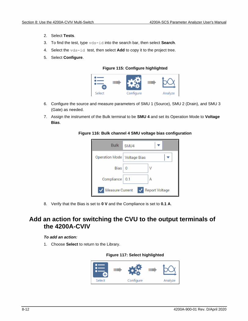
Section 8: Use the 4200A-CVIV Multi-Switch 4200A-SCS Parameter Analyzer User's Manual
8-12 4200A-900-01 Rev. D/April 2020
2. Select Tests.
3. To find the test, type vds-id into the search bar, then select Search.
4. Select the vds-id test, then select Add to copy it to the project tree.
5. Select Configure.
Figure 115: Configure highlighted
6. Configure the source and measure parameters of SMU 1 (Source), SMU 2 (Drain), and SMU 3
(Gate) as needed.
7. Assign the instrument of the Bulk terminal to be SMU 4 and set its Operation Mode to Voltage
Bias.
Figure 116: Bulk channel 4 SMU voltage bias configuration
8. Verify that the Bias is set to 0 V and the Compliance is set to 0.1 A.
Add an action for switching the CVU to the output terminals of the 4200A-CVIV
To add an action:
1. Choose Select to return to the Library.
Figure 117: Select highlighted

4200A-SCS Parameter Analyzer User's Manual Section 8: Use the 4200A-CVIV Multi-Switch
4200A-900-01 Rev. D/April 2020 8-13
2. Select Actions.
3. To find the action, type cviv into the search bar, then select Search.
4. Select the cviv-configure action, then select Add to copy it to the project tree.
Configure the action
To configure the action:
1. Select Configure.
Figure 118: Configure highlighted
2. In the project tree, select the cviv-configure action.
Figure 119: Populated cviv-configure action
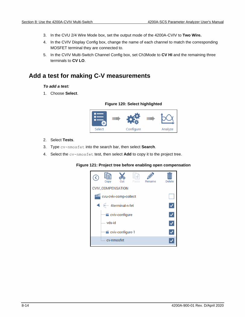
Section 8: Use the 4200A-CVIV Multi-Switch 4200A-SCS Parameter Analyzer User's Manual
8-14 4200A-900-01 Rev. D/April 2020
3. In the CVU 2/4 Wire Mode box, set the output mode of the 4200A-CVIV to Two Wire.
4. In the CVIV Display Config box, change the name of each channel to match the corresponding
MOSFET terminal they are connected to.
5. In the CVIV Multi-Switch Channel Config box, set Ch3Mode to CV HI and the remaining three
terminals to CV LO.
Add a test for making C-V measurements
To add a test:
1. Choose Select.
Figure 120: Select highlighted
2. Select Tests.
3. Type cv-nmosfet into the search bar, then select Search.
4. Select the cv-nmosfet test, then select Add to copy it to the project tree.
Figure 121: Project tree before enabling open compensation
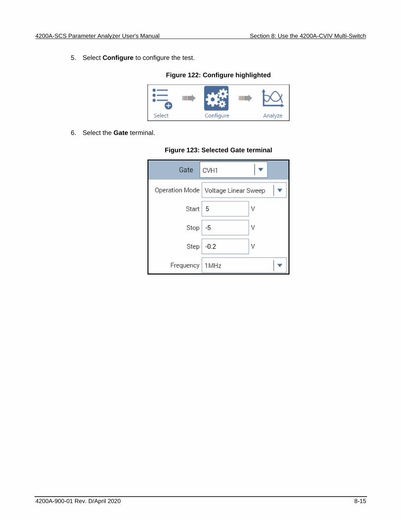
4200A-SCS Parameter Analyzer User's Manual Section 8: Use the 4200A-CVIV Multi-Switch
4200A-900-01 Rev. D/April 2020 8-15
5. Select Configure to configure the test.
Figure 122: Configure highlighted
6. Select the Gate terminal.
Figure 123: Selected Gate terminal

Section 8: Use the 4200A-CVIV Multi-Switch 4200A-SCS Parameter Analyzer User's Manual
8-16 4200A-900-01 Rev. D/April 2020
7. Configure the voltage settings and test frequency as needed.
8. In the right pane, select Terminal Settings and enable Open compensation.
Figure 124: Terminal Settings panel with Open compensation selected

4200A-SCS Parameter Analyzer User's Manual Section 8: Use the 4200A-CVIV Multi-Switch
4200A-900-01 Rev. D/April 2020 8-17
Run the project and review the results
To run the project and review the results:
1. Select the test name at the top of the project tree. In this example, it is CVIV_COMPENSATION.
2. Select Run to start the test. The two actions and two tests run sequentially, and the 4200A-CVIV
is configured by the cviv-configure action.
3. Select Analyze to view the results.
Figure 125: Analyze highlighted
4. Select the cv-nmosfet test to view the results of the C-V test.
5. Select the vds-id test to view the results of the I-V test.


In this section:
Introduction .............................................................................. 9-1 Equipment required .................................................................. 9-2 Device connections .................................................................. 9-2 Set up the measurements in Clarius ........................................ 9-4
Introduction
The Model 4225-PMU Ultra-Fast I-V Module can be used to make both pulsed I-V measurements and
transient I-V measurements (waveform capture) on a device.
Pulsed I-V refers to a test with a pulsed voltage source and a corresponding high speed, time-based
current measurement that provides DC-like results. You can define the parameters of the pulse,
including the pulse width, duty cycle, rise/fall times, and amplitude.
Transient I-V, or waveform capture, is a time-based current and/or voltage measurement that is
typically the capture of a pulsed waveform. Transient I-V measurements can be used to test a
dynamic test circuit or as a diagnostic tool for choosing the appropriate pulse settings in the pulsed
I-V mode.
This section provides an example of how to use the 4225-PMU and the optional Model 4225-RPM
Remote Preamplifier/Switch Module to make a pulsed I-V measurement on a MOSFET. The example
explains how to set up a pulsed voltage step applied to the gate terminal using PMU1 channel 1 and
a pulsed voltage sweep to the drain terminal using PMU1 channel 2. The drain current is measured
as a function of the drain voltage and displayed in the graph in the Analyze pane.
Section 9
PMU for pulsed I-V measurements on a MOSFET

Section 9: PMU for pulsed I-V measurements on a MOSFET 4200A-SCS Parameter Analyzer User's Manual
9-2 4200A-900-01 Rev. D/April 2020
Equipment required
• One 4200A-SCS with the following instruments:
▪ One 4225-PMU
▪ Two 4225-RPMs
• Two CA-547-2A RPM interconnect cables (supplied with the 4225-RPM)
• Two CS-712 male triaxial to female BNC adapters, guard removed (supplied with 4225-RPM)
• Two CS-1247 male BNC to female SMA adapters (supplied with the 4225-RPM)
• Two CA-452A SMA to SMA cables (supplied with the 4225-RPM)
• Two 4200-PRB-C SMA to SSMC Y adapter cables
Device connections
Using the supplied cables, make connections from the output terminals of the two 4225-RPMs to the
MOSFET.
Hazardous voltages may be present on all output and guard terminals. To prevent electrical
shock that could cause injury or death, never connect or disconnect from the 4200A-SCS
while the output is on.
To prevent electric shock, test connections must be configured such that the user cannot
come in contact with test leads, conductors, or any device under test (DUT) that is in contact
with the conductors. It is good practice to disconnect DUTs from the instrument before
powering up the instrument. Safe installation requires proper shields, barriers, and grounding
to prevent contact with test lead and conductors.
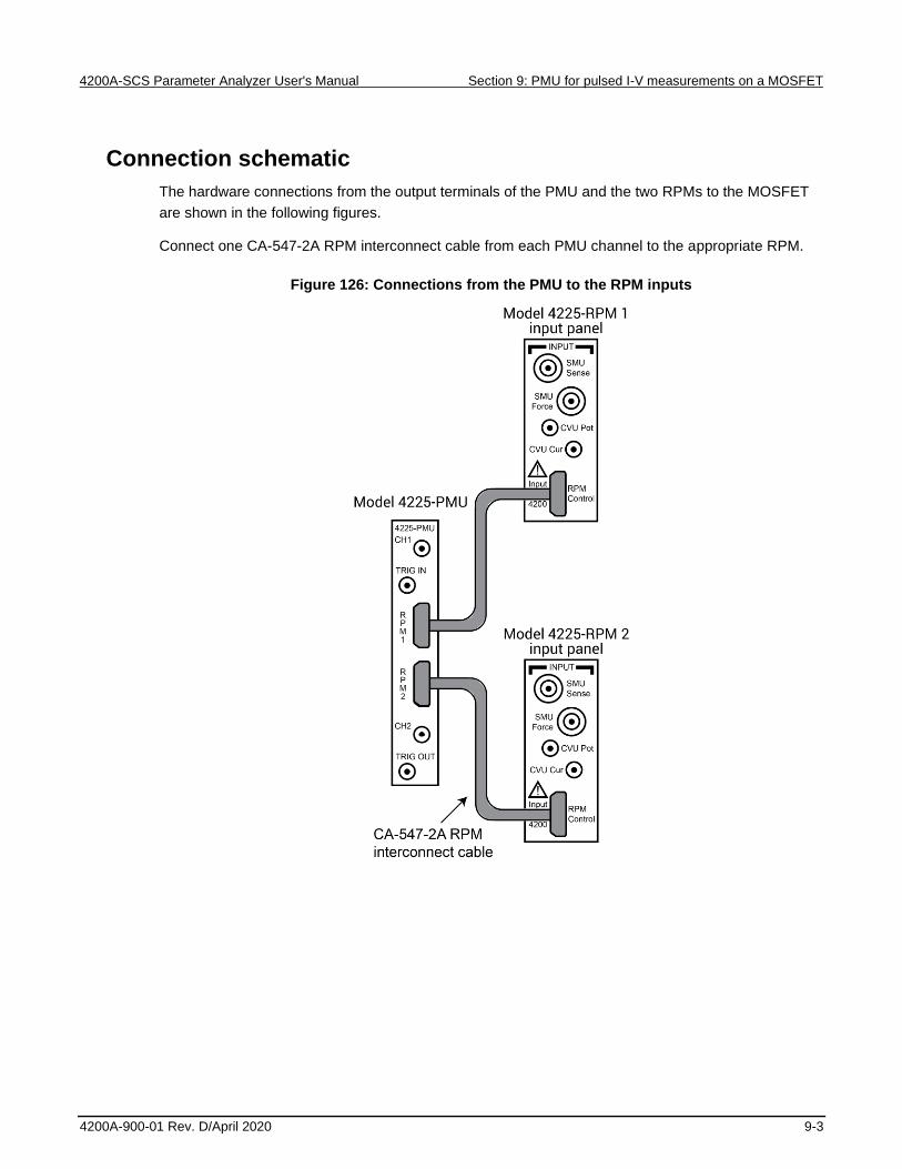
4200A-SCS Parameter Analyzer User's Manual Section 9: PMU for pulsed I-V measurements on a MOSFET
4200A-900-01 Rev. D/April 2020 9-3
Connection schematic
The hardware connections from the output terminals of the PMU and the two RPMs to the MOSFET
are shown in the following figures.
Connect one CA-547-2A RPM interconnect cable from each PMU channel to the appropriate RPM.
Figure 126: Connections from the PMU to the RPM inputs

Section 9: PMU for pulsed I-V measurements on a MOSFET 4200A-SCS Parameter Analyzer User's Manual
9-4 4200A-900-01 Rev. D/April 2020
At the output of each RPM, connect the triaxial to BNC adapter, BNC to SMA adapter, and finally the
SMA-to-SMA cable.
Connect the SMA cables to either probes or a test fixture that is connected to the MOSFET. RPM1 is
connected to the gate of the MOSFET and RPM2 is connected to the drain of the MOSFET.
The shields of the SMA cables are the PMU LO connection and must be connected to the source and
bulk terminals of the MOSFET. The shields of the two SMA cables should be connected together as
close as possible to the device.
The example below illustrates connections from the RPMs to the SMA to SSMC adapter cables
(4200-PRB-C) and then to the probes and device terminals on a wafer. For more information on these
and similar connections, see the Model 4200A-SCS Reference Manual.
Figure 127: Connections from RPM outputs to the MOSFET on a wafer
Set up the measurements in Clarius
This section describes how to set up the Clarius application to make a pulsed I-V sweep on a
MOSFET.
For this example, you will use the Clarius application to:
• Create a new project
• Search for and select an existing test
• Configure the test
• Run the test and analyze the results

4200A-SCS Parameter Analyzer User's Manual Section 9: PMU for pulsed I-V measurements on a MOSFET
4200A-900-01 Rev. D/April 2020 9-5
Create a new project
To create a new project:
1. Choose Select.
Figure 128: Select highlighted
2. In the Library, select Projects.
3. Select New Project.
4. Select Create.
Figure 129: Select a New Project from the Project Library
5. Select Yes when prompted to replace the existing project.
6. Assign a new title to the project by selecting Rename and then entering MOSFET Pulse I-V.
7. Select Enter.

Section 9: PMU for pulsed I-V measurements on a MOSFET 4200A-SCS Parameter Analyzer User's Manual
9-6 4200A-900-01 Rev. D/April 2020
Search for and select an existing test
To search for and select an existing test:
1. Select Tests.
2. Type MOSFET into the search bar, then select Pulse in the Filters pane under Measurements.
3. Select the MOSFET Pulse I-V Drain Family of Curves (pulse-vds-id) test, then Add it to the
project tree. Notice that the device is automatically added.
Figure 130: Selecting the MOSFET Pulse I-V Drain Family of Curves test from the Test library
Configure the test
To configure the test:
1. Select Configure.
Figure 131: Configure button highlighted

4200A-SCS Parameter Analyzer User's Manual Section 9: PMU for pulsed I-V measurements on a MOSFET
4200A-900-01 Rev. D/April 2020 9-7
2. From the Key Parameters pane, adjust the pulse voltage sweep levels of PMU1-2 on the Drain
terminal and the Pulse Step Voltage of PMU1-1 on the Gate terminal, as needed.
Figure 132: Key Parameters pane for the pulse-vds-id test

Section 9: PMU for pulsed I-V measurements on a MOSFET 4200A-SCS Parameter Analyzer User's Manual
9-8 4200A-900-01 Rev. D/April 2020
3. From the Test Settings pane and Advanced Test Settings dialog box, adjust the Pulse Settings
and Timing Parameters, as needed.
Figure 133: Test Settings pane and Test Settings Advanced dialog box
4. From the Terminal Settings pane and Advanced Terminal Settings dialog box, you can adjust the
voltage source and current measurement parameters, as needed.
Figure 134: Terminal Settings pane and Terminal Settings Advanced dialog box

4200A-SCS Parameter Analyzer User's Manual Section 9: PMU for pulsed I-V measurements on a MOSFET
4200A-900-01 Rev. D/April 2020 9-9
Run the test and analyze the results
Select Run to execute the test.
Figure 135: Run
You can select Analyze when you run the project to view test results in real-time.
Figure 136: Analyze highlighted
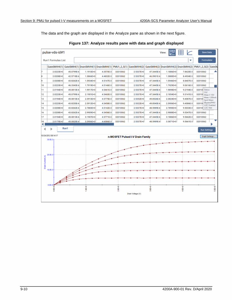
Section 9: PMU for pulsed I-V measurements on a MOSFET 4200A-SCS Parameter Analyzer User's Manual
9-10 4200A-900-01 Rev. D/April 2020
The data and the graph are displayed in the Analyze pane as shown in the next figure.
Figure 137: Analyze results pane with data and graph displayed
In this section:
Additional information ............................................................. 10-1
Additional information
This manual has prepared you to start using your new 4200A-SCS Parameter Analyzer for your
applications. For more detailed information, refer to the Learning Center, which you can access by
selecting this icon on your desktop:
Figure 138: 4200A-SCS Learning Center icon
Section 10
Next steps

Section 10: Next steps 4200A-SCS Parameter Analyzer User's Manual
10-2 4200A-900-01 Rev. D/April 2020
The Learning Center contains a variety of content to help you learn how to use your 4200A-SCS,
including:
• The Model 4200A-SCS Parameter Analyzer Reference Manual
• Videos
• Application notes
• Release notes
• Test and device descriptions
• The Keithley Instruments Low-Level Measurements Handbook
Also see the Keithley Instruments website (tek.com/keithley) for support and additional information
about the instrument, including:
• Updated drivers
• Keithley forums
• Information about related products
Your local Field Applications Engineer can help you with product selection, configuration, and usage.
Check the website for contact information.

Specifications are subject to change without notice.
All Keithley trademarks and trade names are the property of Keithley Instruments.
All other trademarks and trade names are the property of their respective companies.
Keithley Instruments
Corporate Headquarters • 28775 Aurora Road • Cleveland, Ohio 44139 • 440-248-0400 • Fax: 440-248-6168 • 1-800-935-5595 • www.tek.com/keithley
12/17