Model 410 Series Syringe Pumps User s Manual Model 410 Series... · connected to earth ground. ......
42
Model 410 Series Syringe Pumps User’s Manual Publicaon 5605-001 REV-G
Transcript of Model 410 Series Syringe Pumps User s Manual Model 410 Series... · connected to earth ground. ......
Model 410 Series Syringe PumpsUser’s Manual
Publication 5605-001 REV-G

1 Publication 5605-001 REV-G
Table of Contents
SUBJECT PAGE #
General Safety Summary 3
General Description 4
Technical Specifications 4
Features 6
Operating InstructionsPower Switch 9
Syringe Loading 9
KDS410 Withdrawal Operation 12
Units Setting 12
Rate Setting 13
Power Up (run or stop) 13
Run/Stop 13
Change or Review Volume Setting While Running 14
Mode Selection 14
Infusion 14
Withdrawal 14
Infusion/Withdrawal 14
Withdrawal/Infusion 15
Continuous 15
Manual Stall Setting and Microliter Syringes 15
Glass Syringes 15
Clearing a Stall Condition 16
NV Ram Failure 16
RS232 Setup 16
RS232 Commands 17
2 Publication 5605-001 REV-G
Table of Contents
SUBJECT PAGE #
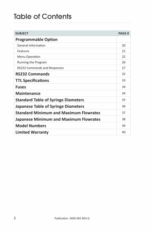
Programmable Option General Information 20
Features 21
Menu Operation 22
Running the Program 26
RS232 Commands and Responses 27
RS232 Commands 32
TTL Specifications 33
Fuses 34
Maintenance 34
Standard Table of Syringe Diameters 35
Japanese Table of Syringe Diameters 36
Standard Minimum and Maximum Flowrates 37
Japanese Minimum and Maximum Flowrates 38
Model Numbers 39
Limited Warranty 40

3 Publication 5605-001 REV-G
General Safety Summary
CAUTIONRefer to Manual
CAUTION: This pump is not registered with the FDA and is not for clinical use on human or veterinary patients. It is intended for research use only.
Please read the following safety precautions to ensure proper use of your syringe pump. To avoid potential hazards and product damage, use this product only as instructed in this manual. If the equipment is used in a manner not specified by the manufacturer, the protection provided by the equipment may be impaired.
To Prevent Hazard or Injury:Avoid Exposed Citcuitry
Do not touch any electronic circuitry inside of the product.
Do Not Operate with Suspected Failures
If damage is suspected on or to the product do not operate the product. Contact qualified service personnel to perform inspection.
Ground the Product
This product is grounded through the grounding conductor of the power cord. To avoid electric shock, use only approved line cord with the product and ensure it is connected to earth ground.
Make Proper Connections
Make sure all connections are made properly and securely. Any signal wire connections to the unit must be no longer than 3 meters.
Observe all Terminal Ratings
Review the operating manual to learn the ratings on all connections.
Use Proper Line Cord
Use only the line cord shipped with the product and make sure line cord is certified for country of use.
Observe all Warning Labels on Product
Read all labels on product to ensure proper usage.
Protective Ground Terminal

4 Publication 5605-001 REV-G
General Description
This manual applies to the KDS410 series infusion/withdrawal pump.
Operation of the pump is simplified by using a keypad to select features from a menu on the alphanumeric display.
All control functions are performed automatically by the pump microcontroller and are based on the syringe diameter and linear motion of the pusher block to deliver a known volume. After entering the syringe diameter, either directly or from a table in memory, a dispense volume and flow rate can be entered, and then all calibration and control functions are performed by the pump automatically.
Technical Specifications
Model 410 Series
Syringe Size 10 microliter - 140 milliliter
Electrical Rating Model 115V~, 0.25A
CE model 230V~, 0.16 A
Fuse 5 x 20 mm, 250V~, slow blow, 0.25A
Voltage Operating Range
Model 100-120V~, 50/60Hz
CE model 200-240V~, 50/60Hz
Drive Mechanism Microprocessor controlled stepper motor ½ - ⅟16
microstepping, driving a leadscrew through a belt and pulley drive mechanism
Pusher Advance per Microstep
(⅟16 step) - 0.165 mm (or .0000064 in)
Volume per Microstep (⅟16) with 60 ml BD syringe - 0.0919µl
Step Rate
Min 1 (⅟16 step)/120 secs
Max 1600 (½ step)/sec
Linear Travel Rate
Min 4.95 x 10⁻⁴ cm/hr
Max 12.67 cm/min
Flowrate Range 5.746 µl/hr - 147.067 ml/min (140 ml syringe)

5 Publication 5605-001 REV-G
Nominal Linear Force >100 Ibs
Dimensions, H x W x D 15 x 28 x 24 cm (6 x 11 x 9.5 in)
Weight 6.4 kg (14 Ibs)
Atmospheric Specs
Temperature 5˚ C - 40˚ C (41˚ F - 104˚ F)
Humidity 20% - 80% RH
Mode of Operation Continuous
Classification Class I
Pollution Degree 2
Installation Category II
Output N/A
Physiological Effects N/A
Cooling Conditions No special considerations
Mechanical Stability No special considerations
Protective Packaging No special considerations
Earth Terminals No External connections required
Removable Protective Means N/A
Supplier Name KD Scientific Inc.
Address 84 October Hill Road, Holliston, MA 01746
Technical Specifications

6 Publication 5605-001 REV-G
Features
1. SYRINGE IDENTIFICATION
Look up Table
The pump contains a table of standard syringes arranged by manufacturer, material and size. Once the syringe is identified in the table the pump automatically enters the appropriate diameter.
Direct Entry
If the syringe used is not included in the table, the internal diameter of the syringe barrel can be measured in millimeters and entered directly from the keypad.
2. INFUSION AND REFILL RATES
The infusion rate and, where applicable, the withdrawal rate can be set independently and can be changed while the pump is running. After the operating mode selection is made the program will prompt only for the relevant rates associated with that mode.
3. VOLUME
A target volume can be entered for infusion and refill independently, and the pump automatically stops when this volume is reached. The pump displays an initial volume of zero and increases as the dispense proceeds to the target volume. The target volume can be reviewed or changed as the pump continues to operate.

7 Publication 5605-001 REV-G
4. MODES OF OPERATION
Infusion
Rate and volume settings: pump infuses to the set volume and stops. Rate setting only: pump runs until manually stopped or stalls.
Withdrawal
Rate and volume settings similar to above.
Infusion/Withdrawal
Infusion automatically followed by withdrawal. Rate and volume settings can be made independently for infusion and withdrawal, hence the pump can infuse at one rate and volume and then change to a different withdrawal flowrate and volume setting.
Withdrawal/Infusion
Withdrawal immediately followed by infusion. Separate settings for rate and volume can be made for withdrawal and infusion.
ContinuousOperation
The pump cycles from infusion to withdrawal continuously. The volume is identical in infuse and withdrawal directions.
Note: The displayed menu which prompts the operator for Rate and Volume settings changes with Mode selection. For convenience, only the relevant settings associated with the selected mode are prompted. For example, in the Withdrawal/Infusion mode the menu prompts for withdraw and then infuse volumes, followed by withdraw and infuse rates. In Infusion only mode, the menu prompts only for infusion volume and infusion rate. In the Continuous mode only one volume is prompted for followed by infusion and withdrawal flow rates.
5. RS232 INTERFACE
Multiple pumps can be controlled in a “daisy chain” by a single PC. Programming is reduced to a small number of simple commands.
6. TTL
Input and output controls are available, such as direction change, run indicator, footswitch or timer control, and valve or relay actuation.
Features

8 Publication 5605-001 REV-G
7. STALL DETECTION
The motor is monitored by an optical encoder to confirm the programmed movement. If the back pressure increases due to jamming or flow restriction then the motor may stall. Stall detection by the encoder results in a pump shutdown.
The display will read “Stalled“. The Stall message can be cleared with the Select key.
8. POWER DISRUPTION
When power is returned after a temporary power disruption the pump can be programmed to resume operation or remain stopped.
However, if a dispense volume is set then the pump always remains stopped.
9. NON-VOLATILE MEMORY
All operational settings are stored in non-volatile memory for convenience, and are used to set the pump when first switched on.
10. SELECTION OF RATE AND VOLUME UNITS
Units of volume (µl or ml) and flowrate (µl/ml per min/hr) can be changed if required.
11. POWER SAVER MODE
When the pump is not running the unit goes into power saver mode. This automatically prevents heat build-up in the pump due to the motor being continually energized.
Features
9 Publication 5605-001 REV-G
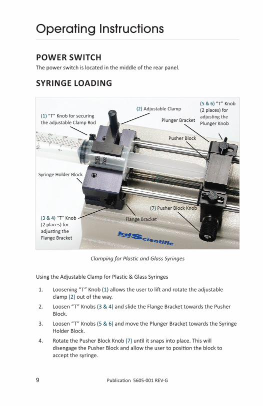
Operating Instructions
POWER SWITCHThe power switch is located in the middle of the rear panel.
SYRINGE LOADING
Clamping for Plastic and Glass Syringes
(1) “T” Knob for securing the adjustable Clamp Rod
(3 & 4) “T” Knob (2 places) for adjusting the Flange Bracket
(5 & 6) “T” Knob (2 places) for adjusting the Plunger Knob
(2) Adjustable Clamp
(7) Pusher Block Knob
Plunger Bracket
Syringe Holder Block
Pusher Block
Flange Bracket
Using the Adjustable Clamp for Plastic & Glass Syringes
1. Loosening “T” Knob (1) allows the user to lift and rotate the adjustable clamp (2) out of the way.
2. Loosen “T” Knobs (3 & 4) and slide the Flange Bracket towards the Pusher Block.
3. Loosen “T” Knobs (5 & 6) and move the Plunger Bracket towards the Syringe Holder Block.
4. Rotate the Pusher Block Knob (7) until it snaps into place. This will disengage the Pusher Block and allow the user to position the block to accept the syringe.

10 Publication 5605-001 REV-G
Operating Instructions
5. Place the syringe in the holder, making sure the flange is resting against the Syringe Holder Block and the plunger is against the Pusher Block. Make sure the plunger flange rests between the bracket and the Pusher Block, and the syringe flange rests between the Flange Bracket and the Syringe Holder Block for proper operation.
6. Rotate the Adjustable Clamp (2) until it rests on the Syringe barrel.
7. While pushing down on the Adjustable Clamp (2), tighten the “T” knob (1).
8. Slide the Flange Bracket towards the Syringe Flange and tighten the “T” knobs (3 & 4).
9. Slide the Plunger Bracket towards the Pusher Block, and tighten the “T” knobs (5 & 6).
10. Engage the Pusher Block by pulling the Knob (7) out and rotate the knob 90˚ clockwise.
11 Publication 5605-001 REV-G
Operating Instructions
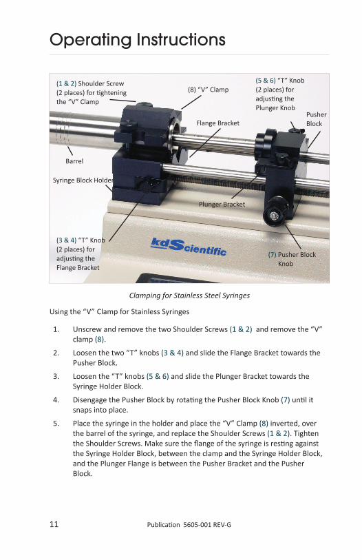
Using the “V” Clamp for Stainless Syringes
1. Unscrew and remove the two Shoulder Screws (1 & 2) and remove the “V” clamp (8).
2. Loosen the two “T” knobs (3 & 4) and slide the Flange Bracket towards the Pusher Block.
3. Loosen the “T” knobs (5 & 6) and slide the Plunger Bracket towards the Syringe Holder Block.
4. Disengage the Pusher Block by rotating the Pusher Block Knob (7) until it snaps into place.
5. Place the syringe in the holder and place the “V” Clamp (8) inverted, over the barrel of the syringe, and replace the Shoulder Screws (1 & 2). Tighten the Shoulder Screws. Make sure the flange of the syringe is resting against the Syringe Holder Block, between the clamp and the Syringe Holder Block, and the Plunger Flange is between the Pusher Bracket and the Pusher Block.
Clamping for Stainless Steel Syringes
(1 & 2) Shoulder Screw (2 places) for tightening the “V” Clamp
(3 & 4) “T” Knob (2 places) for adjusting the Flange Bracket
(5 & 6) “T” Knob (2 places) for adjusting the Plunger Knob
(8) “V” Clamp
(7) Pusher Block Knob
Plunger Bracket
Syringe Block Holder
Barrel
Flange BracketPusher Block
12 Publication 5605-001 REV-G
Operating Instructions
6. Slide the Flange Bracket towards the Syringe Flange and tighten the two “T” Knobs (3 & 4).
7. Slide the Plunger Bracket towards the Syringe Plunger and the Pusher Block and tighten the two “T” Knobs (5 & 6).
8. Engage the Pusher Block by pulling the Plunger Knob (7) out and rotate the knob 90˚ clockwise.
To simplify syringe loading, the pusher block can be disengaged from the leadscrew by turning the knob (7) and manually moved along the guide rods. Alternately, the Fast forward, Fast reverse feature can be used (press Run and respective Arrow key simultaneously).
KDS410 WITHDRAWAL OPERATIONFor withdrawal, or refill operation, the syringe plunger and barrel flange must be secured by the supplied brackets.
UNITS SETTINGprompt: Vol.: 00.00 ml <
The units displayed can be changed if required.
1. Use the RIGHT arrow key to move the pulsing indicator to the units displayed.
2. Continue to use the RIGHT arrow key to scroll through the possible units.
3. The LEFT arrow key will move the active display back to the numerical value.
4. When the correct value and units are displayed press enter.
Possible units are:
• µl and ml
• microliter and milliliter
• µl/m, µl/h and ml/m, ml/h
• µl or ml per minute or hour

13 Publication 5605-001 REV-G
Operating Instructions
RATE SETTINGDisplay reads: Rate 00.01 ml/h >
1. Enter the flowrate value required with the numerical keypad.
2. If necessary, change the units using the → key to move to and scroll through the possible units.
3. When the displayed settings are correct press enter.
Note: If the number entered exceeds the maximum flow rate possible then the pump displays the maximum feasible rate. To continue, enter a rate smaller than the maximum.Note: To check the maximum possible rate enter 9's to the required decimal position. For example, enter 99.9 and the maximum displayed is 12.3 whereas, if 99.99 is entered, then the maximum displayed is 12.34.
POWER UP (run or stop)This option is only applicable when no dispense volume is selected. When power returns after an interruption the pump can resume operation (select RUN) or remain stopped (select STOP).
If the pump resumes operation the rate display will flash to indicate that a power interruption has occurred. Press select to clear the display to resume normal operation.
RUN/STOPAfter all settings are made the pump can be started or stopped by a single press of the run/stop key. During a volume dispense the stop acts as a "pause" and run will resume the dispense.

14 Publication 5605-001 REV-G
Operating Instructions
CHANGE OR REVIEW VOLUME SETTING WHILE RUNNINGWhile the pump continues to run press select to return to the main menu. Scroll through the menu and select Volume to display the set dispense volume.
a. No volume change
Press select. The display returns to the incrementing display volume.
b. Volume change
1. Make the changes with the numerical keypad and enter.
2. The display moves to RATE, permitting a change if required. Use the numerical keypad and enter to make changes (or leave unchanged). The pump immediately changes to the new flowrate, if changed, and the volume continues to increment, uninterrupted by the review process, to the new target dispense volume when it will stop automatically.
Note: If the volume is changed to a volume smaller than the volume already accumulated then the pump will stop as soon as the new, smaller target volume is entered.
MODE SELECTIONMode selection is available only on infusion/withdrawal models.
Select MODE from the main menu and then scroll through the options displayed and select the mode required.
Possible modes are: infusion,withdrawal,infusion/withdrawal,withdrawal/infusion,continuous
Note: For bi-directional modes a volume is required.
infusionPump infuses at the set rate and stops automatically when the target volume is reached. The pump can be manually stopped and restarted at any time, that is, the dispense is paused and, when restarted will continue to the set dispense volume.
withdrawal
Pump withdraws at the set rate to the set volume.
infusion/withdrawal
The pump first infuses and when the target volume is reached it immediately changes direction and withdraws. The volume settings for infusion and withdrawal can be different, as can the infusion and withdrawal flow rates.

15 Publication 5605-001 REV-G
Operating Instructions
withdrawal/infusion
The pump runs first in the withdrawal direction and then automatically changes to the infusion direction. Different settings of rate and volume for withdraw and infuse are permitted.
continuous
The pump first infuses and then withdraws, and then cycles continuously. Only one volume setting for infusion and withdrawal is permitted. If the pump is matched to a valve, which is actuated by a TTL pulse from the pump, this mode can be used to infuse and then refill the pump for continuous operation.
The menu now prompts for volume and rate settings relevant to the mode selected.
MANUAL STALL SETTING AND MICROLITER SYRINGES (not recommended for small syringes)A movable collar, located on the rear guide rod of infusion only pumps, can be set to limit travel of the pusher block. The block moves until stalled against the collar when the electro-optical sensor detects the stall and stops the pump.
Damage to the fine wire plungers of microliter syringes caused by forcing the plunger into the end of the syringe barrel can be prevented by careful adjustment of the collar position.
GLASS SYRINGESIn the withdrawal mode the retaining bracket on the pusher block clamps on the head of the plunger. With some glass syringes the corners of the plunger head are rounded and this may cause the head to ride up out of the retaining bracket.
Similarly in the infusion mode the rounded corners of the syringe barrel flange cause a tendency for the syringe barrel to ride up out of the syringe holder.
To give a more secure, flatter surface to clamp against, an O-ring or metal collar can be placed over the barrel and pressed against the flange.
WARNING: This version pump has enough force to break glass syringes and/or bend thin plungers. Stainless steel syringes should be used in this version pump. Plastic syringes may be used but may fatigue under pressure.
16 Publication 5605-001 REV-G
Operating Instructions
CLEARING A STALL CONDITIONShould a stall occur the pump motor is stopped to prevent damage.
To clear the display press select.
To move the stalled mechanism use the fast forward or fast reverse to move the pusher block. Using the fast forward or fast reverse feature is not only the most simple way to deal with the stall, it also reduces potential damage to the cam mechanism which releases the halfnut from the leadscrew.
NV RAM FAILUREIf the settings in the non-volatile memory become corrupted the display will read “NV Ram Failure” and the pump will not operate.
To recover from this condition the pump must be powered down and then turned on again after a few seconds' delay. The pump will be re-initialized to the default settings and can now be programmed as normal.
If the above fails to work the “NV Ram Failure” message can also be cleared by pressing select and programming a new flow rate. The pump should then be turned off and on to save the settings.
RS232 SETUPThe RS232 connections are made through two modular telephone connectors, labeled IN and OUT , located on the rear panel.
A single PC can control up to 100 pumps via a “daisy chain” using the IN and OUT connectors. When using the daisy chain each pump must be assigned an address and set to the same baud rate. A splitter may be required with greater than 50 pumps.
When controlled via RS232 the pump will still respond to keypad commands but will not respond to keypad and RS232 commands simultaneously. All RS232 command settings, similar to keypad settings, are stored in non-volatile memory.
Select RS232 from the main menu.
Baud Rate 300, 1200, 2400, 4800, 9600
The available baud rates will now be displayed and can be selected using the arrow and select keys. The display now prompts for assignment of a pump address.
Address If no address is assigned then the pump defaults to a 0 setting. All pumps with the same address respond simultaneously to the same commands. Use the → key to enter an address, 0 - 99 and press select to return to the main menu.

17 Publication 5605-001 REV-G
Operating Instructions
RS232 COMMANDSRS232 is used for remote computer control of up to 100 pumps, identified with an address from 0 to 99 and set to the correct baud rate. Each pump can be controlled either from the keypad or via RS232 at all times, but the pump can only respond to one command at a time. When under RS232 control the display reads “REMOTE”. All settings made via RS232 are stored in non-volatile memory.
To move the pump from Remote (RS232) to keypad control press select.
After each command is received and executed by the pump the pump responds with a message and a prompt.
Commands and Responses
Commands are not case sensitive.
After each command is received and executed the pump responds with prompt sequence:
abbreviations: <CR> = carriage return
<LF> = line feed
<SP> = space
<NSP> = no space
a. Commands: Address<SP>command<CR><LF>
b. Response: <CR><LF>address<NSP>prompt
For example: Query pump 2 for withdrawal flow rate ( which is 0.2 ml/minute )
command: 2<SP>ratew?<CR><LF>
response: 0.2<SP>ml/m<CR><LF>2:
Query a single pump for infusion flow rate (which is 0.2 ml/minute )
command: ratei?<CR><LF>
response: 0.2<SP>ml/m<CR><LF>:
Prompts > running in infusion direction
< withdrawing
: stopped
NA not applicable
E error (see error? command)
carriage return <CR> All pumps in the chain interpret this as a stop command
pump address <CR> Pump with the specified address responds with a prompt

18 Publication 5605-001 REV-G
Operating Instructions
pump address (optional), Pump at the address executes the command<CR> command and then responds with a prompt.
Note: If there are multiple pumps in the daisy chain and a pump address is not used then all pumps will respond to the non-specific command and return prompts. Multiple prompts results in a communications breakdown.
Pump commands and responses Note that mode selection and withdrawal and continuous mode commands are recognized only by the infusion/withdrawal models.
run Starts pump running to present settings, returns prompt > or < If already running command is ignored.
stop Stops pump if running, otherwise is ignored. Returns prompt :dia nn.nn Sets syringe diameter in millimeters. n = 0 to 9run? Query run status, returns prompt.del? Queries delivered volume. (Requires a dispense volume to be set).
Response: nnnnn<SP>u Where nnnnn is ., 0 to 9 u are units, µl or ml
dia? Requests present diameter setting. Response: nn.nn Where n = 0 to 9 units always millimeters
ratei? Queries infusion rate. Response: nnnnn<SP>u/u Where nnnnn is ., 0 to 9 u/u are units, µl/m, µl/h, ml/m, or ml/h
ratew? Queries withdrawal rate. Response: nnnnn<SP>u/u Where nnnnn is ., 0 to 9 u/u is rate unit
ratei nnnnn u/u Sets infusion rate. Where is nnnnn is ., 0 to 9, and u/u are units. Units required but if not specified then defaults to automatic setting based on syringe diameter.
ratew nnnnn u/u Sets withdrawal rate. voli nnnnn uu Sets infusion target volume.
Where nnnnn is ., 0 to 9 uu are units µl or ml If units not specified then defaults to automatic setting.
volw nnnnn uu Sets withdrawal target volume.voli? Queries volume setting. Response: nnnnn<SP>uu
Where nnnnn is ·,0 to 9 uu are units µl and ml

19 Publication 5605-001 REV-G
Operating Instructions
mode I Sets mode to infusion.mode w Sets mode to withdrawal.mode I/w Sets mode to infusion/withdrawal.mode w/I Sets mode to withdrawal/infusion.
mode con Sets mode to continuous. Note: A dispense volume must be entered before selecting I/W, W/I and CON modes.
mode? Query mode. Response I, W, I/W, W/I, CONdir rev Changes direction of running pump. Available only in Infusion
and Withdrawal modes.dir? Query direction. Response I (infusion) or W (withdrawal).
Not applicable in infusion only models.error? Command returns values from 0 to 7 as listed below:
0 = no errors 1 = serial error 2 = stall 3 = stall + serial error 4 = serial overrun 5 = serial error + serial overrun 6 = stall + serial overrun 7 = stall + serial error + serial overrun
Errors 8-15 only occur if using pressure switch
8 = overpressure 9 = serial error overpressure 10 = stall + overpressure 11 = stall + serial overrun + overpressure 12 = serial overrun + overpressure 13 = serial error + serial overrun + overpressure 14 = stall + serial overrun + overpressure 15 = stall + serial error + serial overrun + overpressure
Note: sending query also clears all errors.A serial error indicates a command that is too long for the input buffer. A serial overrun indicates that a command has been sent before the prior command has been processed.
A stall error indicates that a stall condition has occured.
Essential that after each command you must wait for the prompt (indicating that the command has been executed) before sending the next command. Also, the prompt will indicate that the command has been executed successfully or not.
prom? Queries software version Response is number 2100.0xx or 2101.0xx or similar

20 Publication 5605-001 REV-G
Programmable Option
General InformationKEYPAD PROGRAMMABLE PUMPSThe “program mode" permits multistep dispenses without the need for computer control.
From the pump keypad, a custom program can be entered, which will control the pump from seconds to days; permit the flowrate to be changed for discrete time periods; repeat dispenses; control output TTL signals to coordinate with other laboratory instruments (or valves); or respond to inputs from other devices, such as switches or relays, and to perform loops, where dispense sequences are repeated.
The program is divided into time periods called STEPS, each of which can be up to 12 hours long. Each step is automatically numbered and, to simplify programming, a menu prompts the user to select the options available in each STEP.
The flowrate can be ramped up or down, or kept constant for a defined time period for a volume dispense. The initial and final flowrate for each period is entered and the pump automatically makes rate changes over the time period. No need to enter increments for a ramp up or down; the pump automatically ramps the rate linearly.
The pump can be paused and then restarted, either by a time delay or by a TTL input. Both TTL inputs and outputs can be controlled by the pump. The pump can therefore, respond to switch closures or send out signals to actuate valve, or other relays, switches etc.
Two separate loops can be programmed so that steps can be repeated. The number of repeat operations is controlled by the “loop count”. For example, this is helpful when a volume dispense is required repeatedly, triggered by a switch.
The two loops can be “nested” so that the program can run for days and complex dispenses can be repeated many times.

21 Publication 5605-001 REV-G
Programmable Option
FeaturesPARAMETERS WHICH CAN BE PROGRAMMED IN EACH STEP Timeduration
Infuse or withdraw
Startflowrate
Endflowrate
TTLoutputsettings
Pause,waitforTTLinputactuation
Loops to repeat previous steps
To simplify the programming, previously programmed settings are stored in non-volatile memory and are displayed when Program Mode is selected. Whenever possible, options are displayed with the “active” option flashing. If flashing, this parameter can be selected or changed.
The pump can be programmed by first selecting MODE on the mainline menu and then selecting Program (PRGM).
DISPLAY AND PROGRAMMING SEQUENCEAfter selecting Program Mode, display reads:Table Dia Step Mode
DIA and TABLE
If the pump was previously used in Program Mode the pump will be initialized in Program Mode when it is switched on. For convenience, should a syringe change be required, it is possible to enter a new syringe size, either from the stored Table or DIA, without leaving the Program Mode.
If a syringe size change is made however, this will change all program values to defaults and will require reprogramming.
It is possible to review the syringe size in “Dia” or “Table” without changing the programmed settings.
In “Table” review the settings but select “QUIT”, do not enter a diameter. In “Dia” the settings will not change if there is no change to the diameter entered.
MODE
Mode selection reverts back to other pump operations.
STEP
Step selection starts the programming sequence.

22 Publication 5605-001 REV-G
Menu OperationAfter selecting MODE and then PROGRAM the display will show STEP which leads into editing the program.
1. Number of STEPS
Menu prompts “NUM of Steps”. Enter total number of program steps using numerical keypad and press SELECT or ENTER to save a maximum of 8.
2. Edit STEP #
The menu automatically increments the step number, however, it is possible to enter a different number. If the step number displayed (flashing) is required then press SELECT to save and continue editing.
3. Time
Step # Time xx:xx:xx.
Time xx:xx:xx in hours, minutes and seconds.
Use the → key to move from left to right and enter the time using the numerical keypad. When the correct time is displayed press ENTER to load this time into memory.
4. Infusion/Withdraw
The direction of travel for each step must be selected.
Initially, “Infusion“ direction will be flashing. The direction keys, → and ← are used to switch between directions. SELECT key is then used to load the direction into memory.
Programmable Option

23 Publication 5605-001 REV-G
Programmable Option
Menu Operation5. Rate
The program requires the initial rate (Start), the ending rate (End), and the units.
a. Display reads: #Start: xxxxx uuu
# is step number, automatically assigned.
xxxxx is the numerical flowrate.
Enter from the numerical keypad.
uuu are flowrate units.
Use the arrow key → to select units (displayed flashing).
Repeat to move through the unit options. Options are: µl/m or µl/h, ml/m or ml/h.
The ← key is used to move back to the numerical display. Press ENTER to save.
The menu now prompts for the final rate which is entered in the same manner.
b. #End: xxxxx uuu; xxxxx numerical and uuu units of flowrate
c. Options:
1. if R1=R2=0 The pump is stopped, no flowrate.
2. if R1<R2 Flowrate increases LINEARLY from R1 to R2 over the step time.
3. if R1>R2 Flowrate decreases LINEARLY from R1 to R2 over the step time.
6. PIN OUT
TTL Output pins can be controlled to set the levels high (H) or low (L) during the step. This change in status of an output pin can be used to trigger another external event.
Pins 1 and 6 on the 9-pin TTL connector can be controlled in the program.
The display reads: # Pinout: 1 = H, 6 = H
Options: HH, HL, LH, LL
The arrow keys are used to toggle through the options. Select and Enter are used to save the settings.

24 Publication 5605-001 REV-G
Programmable Option
Menu Operation7. Pause
If the Pause option is selected in a step, the pump completes the step and pauses at the end of the step.
The display reads: Paused @ end of n; where n is the step number
The pump is programmed but stopped, waiting to be actuated, either by:
a. Run/Stop key
b. “RUN” command via RS232
c. TTL input, Pin 8; level change from High to Low.
The display reads: # Paused: Inactive Active Use arrow key and SELECT to save.
8. Loop
A loop permits the program to return to and execute a previous step, or steps and repeat these steps a specified number of times (up to 100).
The menu first prompts for a loop selection: # Loop?: Yes No
Loop selection is made using the arrow keys to move to Yes or No. SELECT to save.
a. LOOP to STEP The menu now prompts for the Step # the program Loop should return to. For example, if the program is at step 5 and the loop step selected is #3, then the program executes step 3, 4 and 5 again.
b. LOOP COUNT After setting the initial step number of the loop, the menu will prompt for the “loop count”, the number of times the loop will be repeated Maximum repeat number is 100.
Display reads: # Loop Count: x
The number of loops to be executed, x is entered from the numerical keypad followed by ENTER.
Note: a. Maximum number of loops is two. Once both loops are entered the loop option will NOT be displayed in menu. b. ChangingLoops. To change loops, if two are already entered, one loop must be canceled before the new loop can be programmed.c.ALOOP. within a LOOP It is possible to have a loop running within a loop.
25 Publication 5605-001 REV-G
Programmable Option
Menu Operation9. Saving the Step
As there are many options in each step the program gives one more option, “Redo” to make changes before storing the Step. menu prompts: # Step: Save Redo The arrow keys are used to highlight the required option which can be saved with ENTER or SELECT.
10. Program End
After saving the step the program prompts: # Next Step Done “Next Step” is selected, unless all steps are completed, and the above process is repeated for the number of steps required, up to 8. When all steps are programmed “Done” should be entered, with SELECT or ENTER to complete the programming. The pump and display will now move to Step 1 ready to start the programmed dispense. display reads: Stp 1 xx:xx:xx →

26 Publication 5605-001 REV-G
Programmable Option
Running the ProgramRun The Run key starts the program; the displayed time counts down and the direction arrow flashes.
Hold/ContinueIf the Run/Stop key is pressed while running a program, the pump is stopped but gives an option to end the program, or restart the pump and continue the program to its end.
ProgramchangeswhenoperatingOnce a step has commenced no changes are possible in that step. However, while dispensing changes are permitted to steps still to be executed.
SyringesizechangesIf the pump was previously used in Program Mode the pump will be initialized in Program Mode when it is switched on. For convenience, it is possible to enter a new syringe size, either from the stored Table or DIA, without leaving the Program Mode.
Note: If a syringe change is made this will change all program values to the default settings and will require reprogramming. A diameter change causes the pump to stop; resets the “number” of steps to 1; resets the “activestep” to 1; and all values will be set to the initial default settings. The initialization of the new settings takes approximately two seconds.
StallConditionThe Fast Forward & Fast Reverse features do not work in Program Mode. Should a stall occur then go to Infusion Mode where the Fast Forward/Fast Reverse features work, and use these features to end the stall condition.
By going to the infusion mode the program is still saved in memory.
ChangingprogramscontainingloopsOnly two loops are permitted in a program and it is necessary to remove from memory the previously used programs which contain loops. A convenient way to do this is to input a one step program which does not have a loop. This way, all loops are deleted from memory and the new program containing loops can be added.

27 Publication 5605-001 REV-G
Programmable Option
RS232 Commands and ResponsesAll commands and responses in standard pumps remain the same, however, the program mode does have additional commands and responses.
Each pump can be controlled either from the keypad or via RS232 at all times, but the pump can only respond to one command at a time. When under RS232 control the display reads “REMOTE”. All settings made via RS232 are stored in non-volatile memory.
To move the pump from Remote (RS232) to keypad control press select.
Changes to program parameters cannot be made when the pump is running therefore parameter setting commands, such as step, travel, rate etc. are not applicable [NA] when the program is running.
When the pump is running all queries are disallowed except activestep?, timeleft?, and loops?
Commands are not case sensitive.
After each command is received and executed the pump responds with prompt sequence:
a. Query commands:
carriage return (<CR>)line feed, text, <CR>, line feed, 1 or 2 digit address, prompt character
b. Other commands:
<CR>, line feed, 1 or 2 digit address, prompt character
Prompts
> running in infusion direction
< withdrawing
: stopped
NA not applicable
E error (see error? command)
P pump is paused
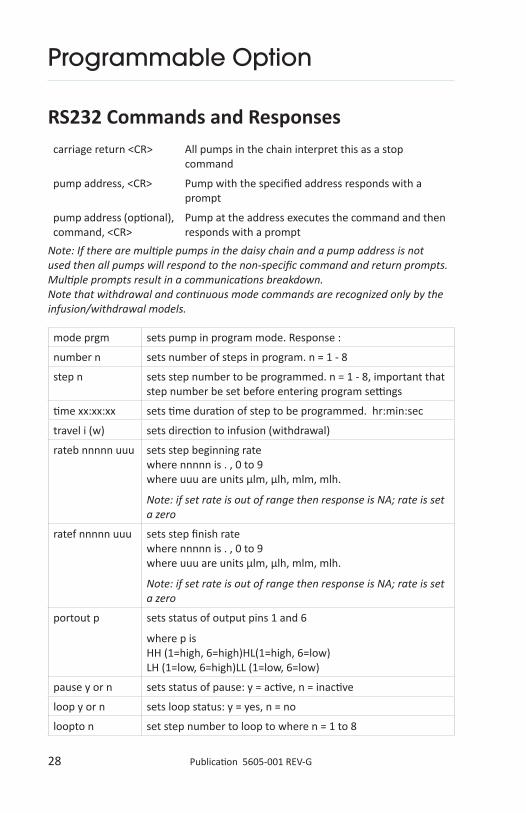
28 Publication 5605-001 REV-G
Programmable Option
mode prgm sets pump in program mode. Response :
number n sets number of steps in program. n = 1 - 8
step n sets step number to be programmed. n = 1 - 8, important that step number be set before entering program settings
time xx:xx:xx sets time duration of step to be programmed. hr:min:sec
travel i (w) sets direction to infusion (withdrawal)
rateb nnnnn uuu sets step beginning rate where nnnnn is . , 0 to 9 where uuu are units µlm, µlh, mlm, mlh.
Note: if set rate is out of range then response is NA; rate is set a zero
ratef nnnnn uuu sets step finish rate where nnnnn is . , 0 to 9 where uuu are units µlm, µlh, mlm, mlh.
Note: if set rate is out of range then response is NA; rate is set a zero
portout p sets status of output pins 1 and 6
where p is HH (1=high, 6=high)HL(1=high, 6=low) LH (1=low, 6=high)LL (1=low, 6=low)
pause y or n sets status of pause: y = active, n = inactive
loop y or n sets loop status: y = yes, n = no
loopto n set step number to loop to where n = 1 to 8
RS232 Commands and Responsescarriage return <CR> All pumps in the chain interpret this as a stop
command
pump address, <CR> Pump with the specified address responds with a prompt
pump address (optional), command, <CR>
Pump at the address executes the command and then responds with a prompt
Note: If there are multiple pumps in the daisy chain and a pump address is not used then all pumps will respond to the non-specific command and return prompts. Multiple prompts result in a communications breakdown.Note that withdrawal and continuous mode commands are recognized only by the infusion/withdrawal models.

29 Publication 5605-001 REV-G
Programmable Option
RS232 Commands and Responses
loopcnt b sets number of loops to be repeated where b = 1 to 100
save saves step settings important that each step is saved
done saves all programmed steps important that “done” is entered after all steps saved
wait stops pump (pauses), but can be restarted
continue restarts pump after “wait” command, program continues
nextstep causes program to jump to the next step
mode? query mode. Response PGM
activestep? queries step running response: n where n = 1 to 8
timeleft? queries time remaining in active step response: xx:xx:xx where hr:min:sec
number? queries number of steps in program response: n where n = 1 to 8
step? queries step being programmed (Not the active step) response: n where n = 1 to 8
time? queries time in program step (Not the active step) response: xx:xx:xx where hr:min:sec
travel? queries direction of travel in programmable step (not active step) response: I or W where I is infusion, and W is withdrawal
Note: Prompts > or < indicate direction of active step.
rateb? queries beginning rate response: nnnnn uuu where nnnn is . , 0 to 9, uuu is µl/m, µl/h, ml/m, ml/h
ratef? sets finish rate response: nnnnn uuu where nnnnn is . , 0 to 9, uuu are units µl/m , µl/h, ml/m, ml/h.
portout? queries status of output TTL pins 1 and 6 response HH, HL, LH, LL
pause? queries whether pause response: Y or N where Y is yes, N is no

30 Publication 5605-001 REV-G
Programmable Option
mode prgm Select Program mode
Number 4 Sets number of steps in the program
Step 1 Selects Step 1 for programming
time 00:00:10 Step 1 time duration is 10 seconds
travel I Infusion selected
rateb 0 mlm Step 1 beginning rate is 0 ml/minute
ratef 1 mlm Step 1 finishing rate is 1 ml/minute
portout hh Output pins 1 and 6 set at high/high
pause n Pause inactive
loop n No loops
save Save step settings
PROGRAM EXAMPLESyringe selected, 4.70 mm diameter
RS232 programming
RS232 Commands and Responses
loops? queries whether loops in program response: Sn:x Sn:x where Sn is the step number containing a loop, x is the number of loops remaining to be executed (counts down)
loop? queries loop status in the step response: Y or N where Y is yes, N is no
loopto? queries step number to which program loops (not available if no loops) response: n where n = 1 to 7
loopcnt? queries number of loop repeats (not available if no loops programmed) response: n where n = 1 to 100
NOTE:
a. It is important to save each step before programming next stepb. Only two loops are permitted, therefore recommend to query number of loops in an existing program before modifying the program. If loops are present it will be necessary to delete an existing loop before a new loop can be programmed.
31 Publication 5605-001 REV-G
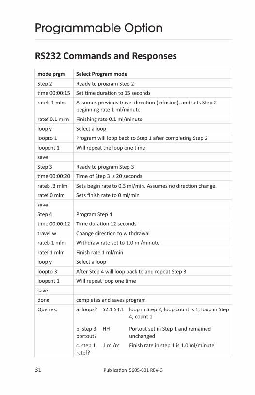
Programmable Option
RS232 Commands and Responses
mode prgm Select Program mode
Step 2 Ready to program Step 2
time 00:00:15 Set time duration to 15 seconds
rateb 1 mlm Assumes previous travel direction (infusion), and sets Step 2 beginning rate 1 ml/minute
ratef 0.1 mlm Finishing rate 0.1 ml/minute
loop y Select a loop
loopto 1 Program will loop back to Step 1 after completing Step 2
loopcnt 1 Will repeat the loop one time
save
Step 3 Ready to program Step 3
time 00:00:20 Time of Step 3 is 20 seconds
rateb .3 mlm Sets begin rate to 0.3 ml/min. Assumes no direction change.
ratef 0 mlm Sets finish rate to 0 ml/min
save
Step 4 Program Step 4
time 00:00:12 Time duration 12 seconds
travel w Change direction to withdrawal
rateb 1 mlm Withdraw rate set to 1.0 ml/minute
ratef 1 mlm Finish rate 1 ml/min
loop y Select a loop
loopto 3 After Step 4 will loop back to and repeat Step 3
loopcnt 1 Will repeat loop one time
save
done completes and saves program
Queries: a. loops? S2:1 S4:1 loop in Step 2, loop count is 1; loop in Step 4, count 1
b. step 3 portout?
HH Portout set in Step 1 and remained unchanged
c. step 1 ratef?
1 ml/m Finish rate in step 1 is 1.0 ml/minute

32 Publication 5605-001 REV-G
RS232 Commands
RS232 Format 8 data bits
No parity
1 stop (can use 2 stops)
Pump uses simple three wire communications - ground, transmit, and receive. No flow control. No handshaking.
Ground GroundGround GroundReceive ReceiveTransmit Transmit
OUT IN
PC with 9-pin connector PC with 25-pin connector
data IN pin 2 data OUT pin 2
data OUT pin 3 data IN pin 3
ground pin 5 ground pin 7

33 Publication 5605-001 REV-G
TTL Specifications
5 4 3 2 1
9 8 7 6
As viewed from rear of the pump
Pin
3 Vss, ground ref.
1,6 Controllable output with Programmable models could be used for relay or valve control (low - infusing, high - refilling)
8 Trigger Falling edge starts /stops pump
e.g. Footswitch
4 Gate Change from high to low - starts when running stays low, change to high - stops
e.g. Footswitch, timer
2 Directional Output high - infuse, low - refill (stays high when stopped)
5 Undefined Input or Output
7 Run Indicator high - running, low - stopped
9 Reverse Direction Normally high; connect to ground (pin 3) reverses. Direction (only applies to infuse/ withdraw mode)
logic low 0 - 0.5V, max 2ma current sink
logic high 2V - 5V

34 Publication 5605-001 REV-G
Fuses
Maintenance
The fuses are located in the power entry module on the rear panel. The linecord must be removed first to gain access to the fuse holder.
Fuse 5 x 20 mm, 250V~ slow blow, 0.25 A
Maintenance is required only for the moving mechanical parts, which should be kept clean and lubricated. Occasionally, a small amount of light machine oil should be applied to the guide rods and a small amount of grease or oil to the leadscrew.
Solvents of any type should never be used to clean the pump. A mild detergent solution may be used to clean the keypad.
35 Publication 5605-001 REV-G
Becton Dickson Glass - all types0.5 cc 4.64 mm1 4.642.5 8.665 11.8610 14.3420 19.1330 22.7060 28.60
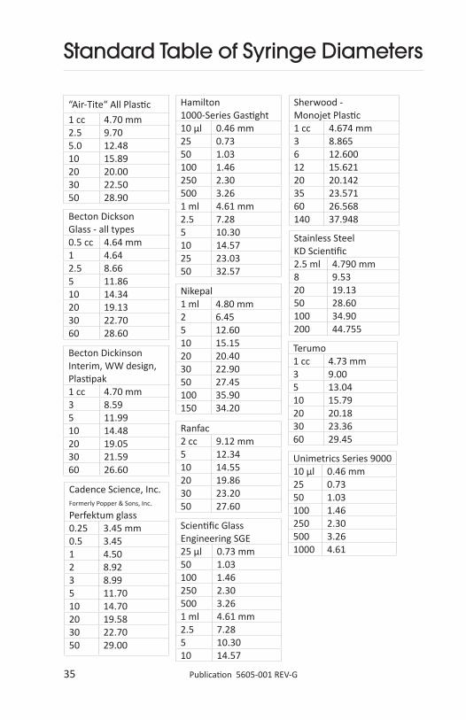
Standard Table of Syringe Diameters
“Air-Tite“ All Plastic
1 cc 4.70 mm2.5 9.705.0 12.4810 15.8920 20.0030 22.5050 28.90
Becton Dickinson Interim, WW design, Plastipak1 cc 4.70 mm3 8.595 11.9910 14.4820 19.0530 21.5960 26.60
Hamilton 1000-Series Gastight10 µl 0.46 mm25 0.7350 1.03100 1.46250 2.30500 3.261 ml 4.61 mm2.5 7.285 10.3010 14.5725 23.0350 32.57
Cadence Science, Inc.Formerly Popper & Sons, Inc. Perfektum glass0.25 3.45 mm0.5 3.451 4.502 8.923 8.995 11.7010 14.7020 19.5830 22.7050 29.00
Ranfac2 cc 9.12 mm5 12.3410 14.5520 19.8630 23.2050 27.60
Scientific Glass Engineering SGE25 µl 0.73 mm50 1.03100 1.46250 2.30500 3.261 ml 4.61 mm2.5 7.285 10.3010 14.57
Sherwood - Monojet Plastic1 cc 4.674 mm3 8.8656 12.60012 15.62120 20.14235 23.57160 26.568140 37.948
Stainless Steel KD Scientific2.5 ml 4.790 mm8 9.5320 19.1350 28.60100 34.90200 44.755
Nikepal1 ml 4.80 mm2 6.455 12.6010 15.1520 20.4030 22.9050 27.45100 35.90150 34.20
Terumo1 cc 4.73 mm3 9.005 13.0410 15.7920 20.1830 23.3660 29.45
Unimetrics Series 900010 µl 0.46 mm25 0.7350 1.03100 1.46250 2.30500 3.261000 4.61

36 Publication 5605-001 REV-G
Becton Dickson Glass - all types0.5 cc 4.64 mm1 4.642.5 8.665 11.8610 14.3420 19.1330 22.7060 28.60
Japanese Table of Syringe Diameters (available in Japanese Models)
“Air-Tite” All Plastic
1 cc 4.70 mm2.5 9.705.0 12.4810 15.8920 20.0030 22.5050 28.90
Becton Dickinson Interim, WW design, Plastipak1 cc 4.70 mm3 8.595 11.9910 14.4820 19.0530 21.5960 26.60
Hamilton 1000-Series Gastight10 µl 0.46 mm25 0.7350 1.03100 1.46250 2.30500 3.261 ml 4.61 mm2.5 7.285 10.3010 14.5725 23.0350 32.57
Terumo1 ml 4.73 mm3 9.005 13.0410 15.7920 20.1830 23.3660 29.45
Nipro1 ml short
6.61 mm
1 ml long
4.75
3 9.535 12.9610 15.7820 20.0730 23.1750 29.13
Hoshi1 ml sm 4.80 mm1 ml lg 6.702 ml sm 6.702 ml lg 9.203 10.305 12.2010 15.0020 19.0030 22.5050 25.50100 34.00
Natsume0.25 ml 2.60 mm0.50 3.201 4.302 6.303 7.305 9.50
Top1 ml 4.70 mm2 6.403 9.306 13.1012 15.4025 21.0030 23.0050 29.00
JMC Air-Tite pls1 ml 4.66 mm2 6.902.5 9.105 12.6210 14.3420 19.6830 22.4450 28.80100 36.68
Terumo Japan
1 ml sm 4.73 mm
1 ml lg 6.50
3 8.95
5 13.00
10 15.80
20 20.15
30 23.10
50 29.10
Stainless Steel KD Scientific2.5 ml 4.790 mm8 9.5320 19.1350 28.60100 34.90200 44.755
Nikepal1 ml 4.80 mm2 6.455 12.6010 15.1520 20.4030 22.9050 27.45100 35.90150 34.20

37 Publication 5605-001 REV-G
Standard Minimum & Maximum Flowrates
Syringe size Diameter* Minimum Maximum
10 µl 0.46 mm 0.001 µl/hr 21.10 µl/min
25 µl 0.73 mm 0.003 µl/hr 53.15 µl/min
50 µl 1.03 mm 0.005 µl/hr 105.8 µl/min
100 µl 1.46 mm 0.009 µl/hr 212.6 µl/min
250 µl 2.3 mm 0.021 µl/hr 527.6 µl/min
500 µl 3.26 mm 0.042 µl/hr 1060 µl/min
1 ml 4.61 mm 0.083 µl/hr 2119 µl/min
2.5 ml 7.28 mm 0.207 µl/hr 5286 µl/min
3 ml 8.59 mm 0.288 µl/hr 7360 µl/min
5 ml 10.3 mm 0.414 µl/hr 634 ml/hr
10 ml 14.57 mm 0.828 µl/hr 1270 ml/hr
20 ml 19.05 mm 1.414 µl/hr 2171 ml/hr
30 ml 21.59 mm 1.817 µl/hr 2789 ml/hr
50 ml 28.9 mm 3.277 µl/hr 4998 ml/hr
60 ml 26.6 mm 2.757 µl/hr 4234 ml/hr
100 ml 34.9 mm 4.746 µl/hr 7289 ml/hr
140 ml 38.4 mm 5.746 µl/hr 8824 ml/hr
Syringes from different manufacturers can have slightly different limits.
Note: *This is a reference diameter used to calculate the flow rate. The specific diameter should be entered for your syringe type.

38 Publication 5605-001 REV-G
Japanese Minimum & Maximum Flowrates (available in Japanese Models)
Syringe size Diameter* Minimum Maximum
10 µl 0.46 mm 0.001 µl/hr 21.10 µl/min
25 µl 0.73 mm 0.003 µl/hr 53.15 µl/min
50 µl 1.03 mm 0.005 µl/hr 105.8 µl/min
100 µl 1.46 mm 0.009 µl/hr 212.6 µl/min
250 µl 2.3 mm 0.021 µl/hr 527.6 µl/min
500 µl 3.26 mm 0.042 µl/hr 1060 µl/min
1 ml 4.7 mm 0.087 µl/hr 2703 µl/min
2.5 ml 9.1 mm 0.323 µl/hr 6259 µl/min
3 ml 9.3 mm 0.337 µl/hr 8626 µl/min
5 ml 12.62 mm 0.7 µl/hr 953 ml/hr
10 ml 14.34 mm 0.802 µl/hr 1230 ml/hr
20 ml 19.68 mm 1.51 µl/hr 2317 ml/hr
30 ml 22.44 mm 1.963 µl/hr 3013 ml/hr
50 ml 28.8 mm 3.232 µl/hr 4963 ml/hr
60 ml 36.68 mm 5.243 µl/hr 8051 ml/hr
Syringes from different manufacturers can have slightly different limits.
Note: *This is a reference diameter used to calculate the flow rate. The specific diameter should be entered for your syringe type.

39 Publication 5605-001 REV-G
Model Numbers
Legacy Model KDS 410Order Code 110 VAC 78-0410
Order Code 220 VAC with CE Mark 78-9410
Notes:KDS 410 pumps with the optional programmable feature contain the number 2 as the last digit.Example: A KDS 410, 100 VAC with optional programmability is part number 78-0412.
40 Publication 5605-001 REV-G
Limited Warranty
KD Scientific Inc. warrants to the first consumer purchaser, for a period of one year from the date of purchase that this unit, when shipped in its original container, will be free from defective workmanship and materials and agree that it will, at its option, either repair or replace the defective unit.
This warranty does not extend to misuse, neglect or abuse, normal wear and tear, accident, modification or unauthorized repair.
KD Scientific will not be liable or in any way responsible for any incidental or consequential economic or property damage. Some States do not allow the exclusion of incidental or consequential damages, so the above exclusion may not apply to you.
There are no implied warranties of merchantability, or fitness for a particular use, or of any other nature. Some states do not allow this limitation on implied warranty, so the above limitation may not apply to you.
If a defect arises within the warranty period contact KD Scientific Inc. (see address below).
The customer is responsible for shipping charges and must first obtain a Return Material Authorization number (RMA) before the unit will be accepted. If a replacement unit is issued it is covered only for the remainder of the original warranty period dating from the purchase of the original device.
This warranty gives you specific legal rights. You may also have other rights which vary from state to state.
Note: This pump is not registered with the FDA and is not for clinical use on patients.
Syringe pumps are manufactured by:
KD Scientific Inc.
84 October Hill Road
Holliston, MA 01746
phone: 508.429.6809 | fax: 508.893.0160
email: [email protected]
www.kdscientific.com
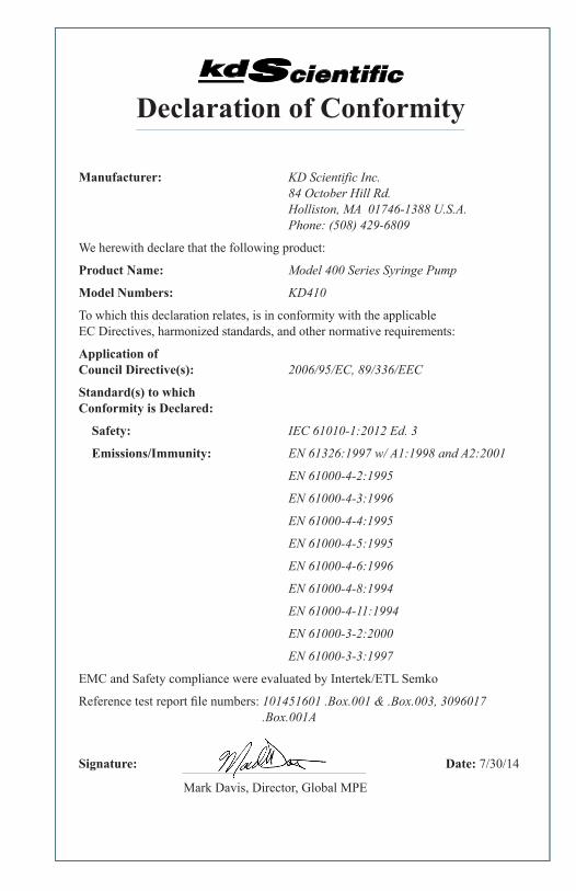
Declaration of Conformity
Manufacturer: KD Scientific Inc. 84 October Hill Rd. Holliston, MA 01746-1388 U.S.A. Phone: (508) 429-6809
We herewith declare that the following product:
Product Name: Model 400 Series Syringe Pump
Model Numbers: KD410
To which this declaration relates, is in conformity with the applicable EC Directives, harmonized standards, and other normative requirements:
Application of Council Directive(s): 2006/95/EC, 89/336/EEC
Standard(s) to which Conformity is Declared:
Safety: IEC 61010-1:2012 Ed. 3
Emissions/Immunity: EN 61326:1997 w/ A1:1998 and A2:2001
EN 61000-4-2:1995
EN 61000-4-3:1996
EN 61000-4-4:1995
EN 61000-4-5:1995
EN 61000-4-6:1996
EN 61000-4-8:1994
EN 61000-4-11:1994
EN 61000-3-2:2000
EN 61000-3-3:1997
EMC and Safety compliance were evaluated by Intertek/ETL Semko
Reference test report file numbers: 101451601 .Box.001 & .Box.003, 3096017 .Box.001A
Signature: Date: 7/30/14
Mark Davis, Director, Global MPE