
Model 3500 Transmitter (9-wire) or Model 3300 Peripheral/media/resources/micro motion/u... · Micro...
16
Micro Motion TM Model 3500 Transmitter (9-wire) or Model 3300 Peripheral Installation Instructions for Panel-Mount Quick Reference Guide P/N 3300994, Rev. C April 2003 For online technical support, use the EXPERT 2 ™ system at www.expert2.com. To speak to a customer service representative, call the support center nearest you: • In the U.S.A., phone 1-800-522-MASS (1-800-522-6277) • In Canada and Latin America, phone (303) 530-8400 • In Asia, phone (65) 6770-8155 • In the U.K., phone 0800 - 966 180 (toll-free) • Outside the U.K., phone +31 (0) 318 495 67
Transcript of Model 3500 Transmitter (9-wire) or Model 3300 Peripheral/media/resources/micro motion/u... · Micro...

Micro MotionTM
Model 3500 Transmitter(9-wire) orModel 3300 PeripheralInstallation Instructions forPanel-Mount
Quick Reference GuideP/N 3300994, Rev. CApril 2003
For online technical support, use the EXPERT2™ system at www.expert2.com. To speak to a customer service representative, call the support center nearest you:
• In the U.S.A., phone 1-800-522-MASS (1-800-522-6277)
• In Canada and Latin America, phone (303) 530-8400
• In Asia, phone (65) 6770-8155
• In the U.K., phone 0800 - 966 180 (toll-free)
• Outside the U.K., phone +31 (0) 318 495 67

1
BEFORE YOU BEGIN
This quick reference guide explains basic installation guidelines for mounting the Micro Motion® Model 3300/3500 applications platform in a panel cutout.
For information on I.S. applications, refer to Micro Motion ATEX, UL, or CSA installation instructions.
For complete instructions about configuration, maintenance, and service, refer to the instruction manual shipped with the transmitter.
WARNING
Improper installation in a hazardous area can cause an explosion.
For information about hazardous applications, refer to Micro Motion ATEX, UL, or CSA installation instructions, shipped with the transmitter or available from the Micro Motion web site.
WARNING
Hazardous voltage can cause severe injury or death.
Install transmitter and complete all wiring before supplying power.
CAUTION
Improper installation could cause measurement error or flowmeter failure.
Follow all instructions to ensure transmitter will operate correctly.
©2003, Micro Motion, Inc. All rights reserved. Micro Motion is a registered trademark of Micro Motion, Inc. The Micro Motion and Emerson logos are trademarks of Emerson Electric Co. All other trademarks are property of their respective owners.

2
European installations
This Micro Motion product complies with all applicable European directives when properly installed in accordance with the instructions in this quick reference guide. Refer to the EC declaration of conformity for directives that apply to this product.
The EC declaration of conformity, with all applicable European directives, and the complete ATEX Installation Drawings and Instructions are available on the internet at www.micromotion.com/atex or through your local Micro Motion support center.
Installation kit
The installation kit includes a bezel, frame, two mounting brackets with screws, a power supply wiring connector, and a retaining clip assembly for power supply wiring (see Figure 1).
The applications platform fits through a 5 7/16-inch (138 mm) square cutout in a panel that is 5/64 inch (2 mm) to 1/2 inch (13 mm) thick. The bezel provides a IP65 watertight seal between the panel cutout and the applications platform housing.
In addition, the installation kit includes:
• A bracketed wiring connector for screw-type connectors (see Figure 5, page 5), or
• I/O cables and connectors (see Figure 7, page 7)
Figure 1. Panel-mount installation kit
Power supplywiring connector
Retaining-clipassembly for
power supply wiring
2 x Mounting bracketwith screw
Frame Bezel
Panel thickness:• 5/64 inch (2 mm) minimum• 1/2 inch (13 mm) maximum

3
STEP 1. Choosing a location
Choose a location for the transmitter based on the requirements described below.
Environmental requirements
Install the transmitter where ambient temperature is between –4 and +140 °F (–20 and +60 °C).
Dimensions
If the Model 3300/3500 has screw-type wiring connectors, see Figure 2 for dimensions. If the Model 3300/3500 has I/O cables, see Figure 3, page 4, for dimensions. (See Figures 5 and 7, pages 5 and 7, for illustrations of screw-type connectors versus I/O cables.)
Figure 2. Panel-mount dimensions – screw-type connectors
4 1/2(115)
6 1/2(165)
Bezel
Panel
6(152)
Approvals tag
Frame
Intrinsic safety shield(Model 3500 only)
7 7/8(200)
1/2(12)
8 1/2(216)
6(152)
inches(mm)
6 11/16(170)

4
Figure 3. Panel-mount dimensions – I/O cables
Flowmeter cable lengthsMaximum cable length from the sensor to the Model 3500 transmitter is 1000 feet (300 meters).
If you are installing the Model 3300 applications peripheral in combination with a transmitter, the maximum cable length from the transmitter’s frequency output to the Model 3300’s frequency input is 500 feet (150 meters).
STEP 2. Installing the Model 3300/3500 in the panel
Refer to Figure 4, page 5, and follow these steps:
1. Insert the Model 3300/3500 through the cutout.
2. Slide the frame over the housing.
3. Insert the posts on the brackets into the rails on the housing.
4. Tighten the screws evenly to 10 to 14 inch-pounds (1,13 to 1,38 Nm) to ensure a watertight seal between the gasket and the panel.
6 1/2(165)
Bezel
Panel
6(152)
6 11/16(170)
Minimum 4 1/4" (108 mm) bend radius
Approvals tag
1/2(12)
8 3/4(222)
5 5/16(135)
Frame
6(152)
inches(mm)

5
Figure 4. Steps for installation in panel
STEP 3. Connecting input and output wiring
If the Model 3300/3500 has screw-type connectors:
1. Plug the bracketed wiring connectors onto the terminal strips on the back panel of the Model 3300/3500 (see Figure 5). Tighten the captive screws to secure the bracket to the back panel.
Figure 5. Wiring connectors and terminals – screw-type connectors
Step 2.1
Step 2.2
Step 2.3 Step 2.4
Non-intrinsically safe input/output wiringterminal strip
Intrinsically safe sensor wiring terminal strip(Model 3500 only)
Intrinsic safety shield(Model 3500 only)
Bracketed wiring connector

6
2. Connect input and output wiring to the appropriate terminals in the input/output wiring connector. Refer to the card that is inserted into the sleeve on the top panel (shown in Figure 6), and Table 1.
• Use 24 to 16 AWG (0,25 to 1,5 mm2) twisted-pair shielded wire.
• Ground the shields at a single point only.
Figure 6. Input/output wiring terminal card – screw-type connectors
If the Model 3300/3500 has I/O cables:
1. Plug the bracketed wiring connector onto the terminal strips on the back panel of the Model 3300/3500 (see Figure 7, page 7). Tighten the captive screws to secure the bracket to the back panel.
Table 1. Input/output wiring terminals – screw-type connectors
Terminal number Designation
c 2+ a 2 – Primary 4–20 mA output
c 4 + a 4 – Secondary 4–20 mA output
c 6 + a 6 – Frequency input
c 8 + a 8 – Discrete input 1
c 10 + a 10 – Discrete input 2
c 12 + a 12 – Frequency output
c 14 + a 14 – Discrete output 1
c 16 + a 16 – Discrete output 2
c 18 + a 18 – Discrete output 3
c 32 (B line) a 32 (A line) RS-485 output
7
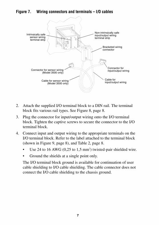
Figure 7. Wiring connectors and terminals – I/O cables
2. Attach the supplied I/O terminal block to a DIN rail. The terminal block fits various rail types. See Figure 8, page 8.
3. Plug the connector for input/output wiring onto the I/O terminal block. Tighten the captive screws to secure the connector to the I/O terminal block.
4. Connect input and output wiring to the appropriate terminals on the I/O terminal block. Refer to the label attached to the terminal block (shown in Figure 9, page 8), and Table 2, page 8.
• Use 24 to 16 AWG (0,25 to 1,5 mm2) twisted-pair shielded wire.
• Ground the shields at a single point only.
The I/O terminal block ground is available for continuation of user cable shielding to I/O cable shielding. The cable connector does not connect the I/O cable shielding to the chassis ground.
Non-intrinsically safe input/output wiringterminal strip
Intrinsically safesensor wiringterminal strip
Bracketed wiring connector
Cable for input/output wiringCable for sensor wiring
(Model 3500 only)
Connector for input/output wiringConnector for sensor wiring
(Model 3500 only)

8
Figure 8. Installing terminal block for I/O wiring on DIN rail
Figure 9. Input/output wiring terminal card – I/O cables
Table 2. Input/output wiring terminals – I/O cables
Terminal number Designation
1 + 2 – Secondary 4–20 mA output14 + 15 – Primary 4–20 mA output3 + 4 – Frequency input5 + 6 – Discrete input 17 + 8 – Discrete input 216 + 17 – Frequency output18 + 19 – Discrete output 120 + 21 – Discrete output 222 + 23 – Discrete output 324 (B line) 25 (A line) RS-485 output
DIN rail type TS 15 DIN rail type TS 32
DIN rail type TS 35 x 7,5
3 3/64(77)
9(229)
Label ismounted
here
3 17/32(90)
Cable for input/output wiring
Connector
I/O terminal block
DIN rail type TS 35 x 15
2 37/64(66)
2 31/64(63)
2 19/64(59)
2 1/4(57) 2 15/64
(57)
inches(mm)

9
STEP 4. Connecting the Model 3500 to the sensor
To connect the Model 3500 transmitter to a Micro Motion sensor, follow the steps below. If you are installing the Model 3300 applications peripheral, this step is not required.
Sensor wiring depends on the connectors supplied with the Model 3500:
• Screw-type connectors
• I/O cables
Follow the steps below to connect the Model 3500 to the sensor.
1. Identify the components:
• See Figure 10 for transmitters with screw-type connectors.
• See Figure 11, page 10, for transmitters with I/O cables.
Figure 10. Sensor cable to Model 3500 – screw-type connectors
brown
yellowvioletgreen
bluered
black (drains)orangewhitegray
9-wire cable from sensor
brownred
greenwhite
bluegray
orange
violetyellow
black (drain wires from all wire sets)
Model 3500Sensor wiring terminals(see Figure 5, page 5)
c
c
c
c
c
c
c
c
c
c
c
c
c
c
c
c
2
4
6
8
10
12
14
16
18
20
22
24
26
28
30
32
a
a
a
a
a
a
a
a
a
a
a
a
a
a
a
a

10
Figure 11. Sensor cable to Model 3500 – I/O cables
2. Prepare the cable according to the instructions in Micro Motion’s 9-Wire Flowmeter Cable Preparation and Installation Guide.
3. Ensure that the cable has 360° shielding, continuous from the transmitter to the sensor’s junction box. Two methods can be used:
• Metallic conduit
• Shielded or armored cable
Refer to Micro Motion’s 9-Wire Flowmeter Cable Preparation and Installation Guide for specific instructions.
4. At the sensor:
a. Clip the cable drain wires.
b. Connect wiring inside the junction box housing and tighten the screws to hold the wires in place.
For information on your sensor’s junction box terminals, see the sensor installation manual or Micro Motion’s 9-Wire Flowmeter Cable Preparation and Installation Guide.
brownredorangeyellowgreenbluevioletgray
whiteblack (drains)
Connect outer braid ofshielded or armored
cable here
Model 3500 sensor wiring terminalsTerminal block for sensor wiring
installed on DIN rail (see Figure 12, page 11)
9-wire cable from sensor
brownred
greenwhite
bluegrayorange
violetyellow
black (drain wires from all wire sets)
11
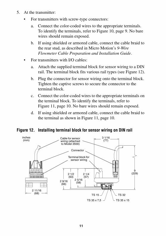
5. At the transmitter:
• For transmitters with screw-type connectors:
a. Connect the color-coded wires to the appropriate terminals. To identify the terminals, refer to Figure 10, page 9. No bare wires should remain exposed.
b. If using shielded or armored cable, connect the cable braid to the rear stud, as described in Micro Motion’s 9-Wire Flowmeter Cable Preparation and Installation Guide.
• For transmitters with I/O cables:
a. Attach the supplied terminal block for sensor wiring to a DIN rail. The terminal block fits various rail types (see Figure 12).
b. Plug the connector for sensor wiring onto the terminal block. Tighten the captive screws to secure the connector to the terminal block.
c. Connect the color-coded wires to the appropriate terminals on the terminal block. To identify the terminals, refer to Figure 11, page 10. No bare wires should remain exposed.
d. If using shielded or armored cable, connect the cable braid to the terminal as shown in Figure 11, page 10.
Figure 12. Installing terminal block for sensor wiring on DIN rail
2 11/16(68)
TS 15 TS 32
TS 35 x 7,5 TS 35 x 15
9(229)
3 1/16(77)
2 1/4(57)
2 5/16(58)
2 1/2(63)
2 9/16(66)
inches(mm)
Terminal block for sensor wiring
Cable for sensor wiring (attached to Model 3500)
Connector

12
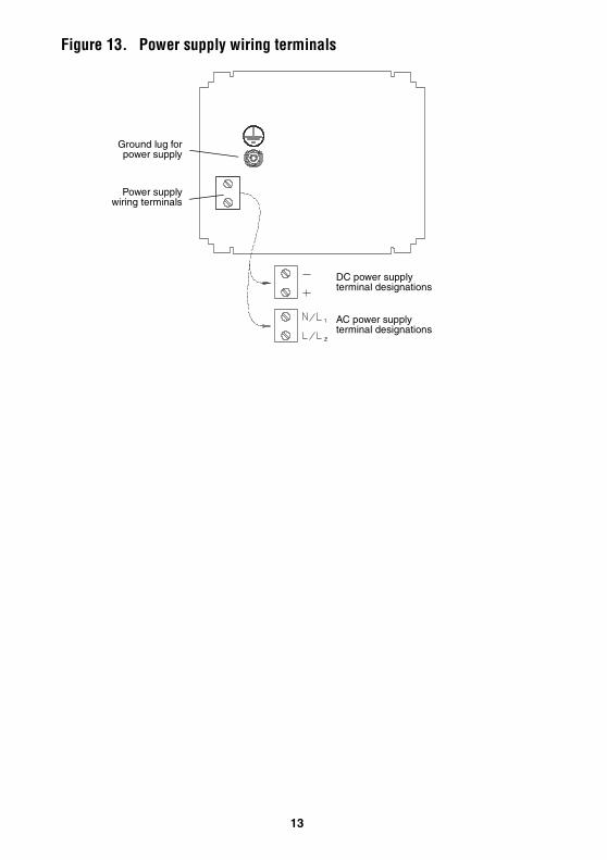
STEP 5. Connecting power supply wiring
Connect the Model 3300/3500 to a power supply as follows:
1. Plug in the power supply wiring connector. See Figure 13, page 13.
2. Connect 18 to 14 AWG (0,75 to 2,5 mm2) wiring to the power supply wiring connector.
3. Ground the power supply wiring:
• Connect the ground wire to the ground lug for the power supply.
• Connect the power supply ground directly to earth ground.
• Keep all ground leads as short as possible.
• Ensure that all ground wiring has less than 1 ohm impedance.
4. Connect wires to the power supply wiring terminals as shown in Figure 13, page 13.
5. Slide the retaining clip over the wiring, then tighten the screw to hold the clip in place. See Figure 1, page 2.
A user-supplied switch may be installed in the power supply line. For compliance with low-voltage directive 73/23/EEC (European installations), a switch in close proximity to the Model 3300/3500 is required.
CAUTION
Improper wiring installation can cause device failure or measurement error.
• To avoid device failure or measurement error, do not install power supply wiring in the same cable tray or conduit as input/output wiring.
• Shut off power supply before installing the applications platform.
• Make sure power supply voltage matches voltage that is indicated on power supply wiring terminals. See Figure 13, page 13.
13
Figure 13. Power supply wiring terminals
DC power supply terminal designations
AC power supply terminal designations
Ground lug forpower supply
Power supplywiring terminals


Micro MotionTM
Micro Motion EuropeEmerson Process ManagementWiltonstraat 303905 KW VeenendaalThe NetherlandsT +31 (0) 318 495 670F +31 (0) 318 495 689
Micro Motion United KingdomEmerson Process Management LimitedHorsfield WayBredbury Industrial EstateStockport SK6 2SU U.K.T 0800 966 180F 0800 966 181
Micro Motion JapanEmerson Process ManagementShinagawa NF Bldg. 5F1-2-5, Higashi ShinagawaShinagawa-kuTokyo 140-0002 JapanT (81) 3 5769-6803F (81) 3 5769-6843
Micro Motion AsiaEmerson Process Management1 Pandan CrescentSingapore 128461Republic of SingaporeT (65) 6777-8211F (65) 6770-8003
Micro Motion Inc. USAWorldwide Headquarters7070 Winchester CircleBoulder, Colorado 80301T (303) 530-8400
(800) 522-6277F (303) 530-8459
©2003, Micro Motion, Inc. All rights reserved. P/N 3300994, Rev. C
*3300994*
Visit us on the Internet at www.micromotion.com