Model 3200 Liquid Level Controller - Flow-Zoneflow-zone.com/pdf/mallard/Level Indicators and...
8
The Model 3200 Liquid Level Controller is ideal for oilfield scrubber and separator applications. Its rugged and versatile design make it the preferred choice of production operators for reliable service in a wide variety of applications. Available in caged and cageless configurations; pneumatic snap and throttling pilots, or electric SPDT and DPDT limit switches; direct or reverse action; with a variety of displacer sizes, materials, and vessel connections. Features: • Pneumatic Non-bleeding Pilots - The Model 3200 can be fitted with either of two non-bleeding pilots: a snap pilot for on/off service or a throttle pilot for modulating service. The controller can be quickly and easily converted from snap to throttle or vice versa. • Electric Pilots - The Model 3200 is also available with explosion-proof SPDT or DPDT electric switches. • Weather-Proof Case - Utilizes a gasket between its cover and case to seal out the effects of outside weathering. • Field Reversible Action - The Model 3200 design makes reversing the controller action simple. Requires no additional parts or special tools. • Liquid-Liquid Interface Control - The Model 3200 is well-suited for liquid-liquid interface detection. • Displacers - Mallard offers a variety of displacer materials and designs for the Model 3200 to satisfy your design and application requirements. Standard material offerings are PVC, Acrylic, and 316 Stainless Steel. • NACE - The Model 3200 is available with wetted materials that meet NACE MR-01-75 specifications for sour service. zMallard Control Company, Inc. 2003; All Rights Reserved 5/03 Model 3200 Liquid Level Controller
-
Upload
truongdien -
Category
Documents
-
view
213 -
download
0
Transcript of Model 3200 Liquid Level Controller - Flow-Zoneflow-zone.com/pdf/mallard/Level Indicators and...

The Model 3200 Liquid Level Controller is ideal for oilfield scrubber and separator applications. Its rugged and versatiledesign make it the preferred choice of production operators forreliable service in a wide variety of applications. Available incaged and cageless configurations; pneumatic snap and throttling pilots, or electric SPDT and DPDT limit switches; director reverse action; with a variety of displacer sizes, materials,and vessel connections.
Features:
• Pneumatic Non-bleeding Pilots - The Model 3200 can be fitted with either of two non-bleeding pilots: a snap pilot for on/off service or a throttle pilot for modulating service. The controller can be quickly and easily converted from snap to throttle or vice versa.
• Electric Pilots - The Model 3200 is also available withexplosion-proof SPDT or DPDT electric switches.
• Weather-Proof Case - Utilizes a gasket between its coverand case to seal out the effects of outside weathering.
• Field Reversible Action - The Model 3200 design makes reversing the controller action simple. Requires no additional parts or special tools.
• Liquid-Liquid Interface Control - The Model 3200 is well-suited for liquid-liquid interface detection.
• Displacers - Mallard offers a variety of displacer materials and designs for the Model 3200 to satisfy your design and application requirements. Standard material offerings are PVC, Acrylic, and 316 Stainless Steel.
• NACE - The Model 3200 is available with wetted materialsthat meet NACE MR-01-75 specifications for sour service.
zMallard Control Company, Inc. 2003; All Rights Reserved 5/03
Model 3200Liquid Level Controller
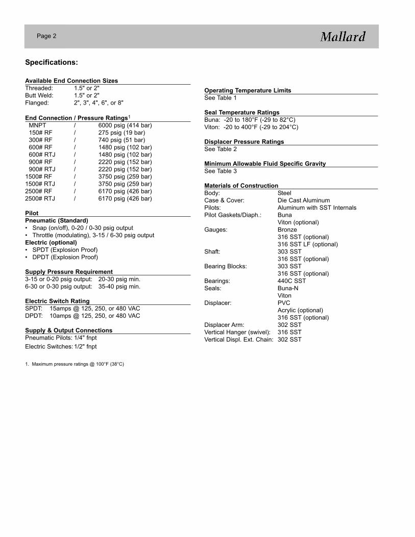
Operating Temperature LimitsSee Table 1
Seal Temperature RatingsBuna: -20 to 180°F (-29 to 82°C)Viton: -20 to 400°F (-29 to 204°C)
Displacer Pressure RatingsSee Table 2
Minimum Allowable Fluid Specific GravitySee Table 3
Materials of ConstructionBody: SteelCase & Cover: Die Cast AluminumPilots: Aluminum with SST InternalsPilot Gaskets/Diaph.: Buna
Viton (optional)Gauges: Bronze
316 SST (optional)316 SST LF (optional)
Shaft: 303 SST316 SST (optional)
Bearing Blocks: 303 SST316 SST (optional)
Bearings: 440C SSTSeals: Buna-N
VitonDisplacer: PVC
Acrylic (optional)316 SST (optional)
Displacer Arm: 302 SSTVertical Hanger (swivel): 316 SSTVertical Displ. Ext. Chain: 302 SST
Specifications:
Available End Connection SizesThreaded: 1.5" or 2"Butt Weld: 1.5" or 2"Flanged: 2", 3", 4", 6", or 8"
End Connection / Pressure Ratings1
MNPT / 6000 psig (414 bar)150# RF / 275 psig (19 bar)300# RF / 740 psig (51 bar)600# RF / 1480 psig (102 bar)600# RTJ / 1480 psig (102 bar)900# RF / 2220 psig (152 bar)900# RTJ / 2220 psig (152 bar)
1500# RF / 3750 psig (259 bar)1500# RTJ / 3750 psig (259 bar)2500# RF / 6170 psig (426 bar)2500# RTJ / 6170 psig (426 bar)
PilotPneumatic (Standard)• Snap (on/off), 0-20 / 0-30 psig output• Throttle (modulating), 3-15 / 6-30 psig outputElectric (optional)• SPDT (Explosion Proof)• DPDT (Explosion Proof)
Supply Pressure Requirement3-15 or 0-20 psig output: 20-30 psig min.6-30 or 0-30 psig output: 35-40 psig min.
Electric Switch RatingSPDT: 15amps @ 125, 250, or 480 VACDPDT: 10amps @ 125, 250, or 480 VAC
Supply & Output ConnectionsPneumatic Pilots: 1/4" fnptElectric Switches:1/2" fnpt
1. Maximum pressure ratings @ 100°F (38°C)
Page 2

Table 1. Operating Temperature Limits
Table 2. Displacer Pressure Ratings
1. For applications requiring higher pressure ratings for SST displacers, consult Factory or your local Mallard representative.
Table 3. Minimum Allowable Fluid Specific Gravity
1. Based on 1.88" dia. x 12" displacer with 12" displacer arm.2. Based on 1.88" dia. x 12" displacer with 15" displacer arm.3. Special displacer and displacer arm configurations required - consult Factory or your local Mallard representative.
Page 3
Body Material Seals Displacer MaterialTemperature Limits
°F °CC.S.C.S.C.S.
BunaBunaBuna
PVCAcrylic
316 SST
-20 to 140°-20 to 180°-20 to 180°
-29 to 60°-29 to 82°-29 to 82°
C.S.C.S.C.S.
VitonVitonViton
PVCAcrylic
316 SST
-20 to 140°-20 to 200°-20 to 400°
-29 to 60°-29 to 93°
-29 to 204°
MaterialMaximum Pressure
Psig Bar
PVCAcrylic
316 SST
61706170
2000 @ 180°F, 1595 @ 400°F1
426426
138 @ 82°C, 110 @ 204°C1
Top Level Control Liquid-Liquid Interface Level Control
PilotHorizontal Displacer Vertical Displacer
PilotHorizontal Displacer Vertical Displacer
Standard1 Standard2 Std1 Special3 Std2 Special3
SnapThrottle
0.280.56
0.210.42
SnapThrottle
0.280.56
0.0300.060
0.210.42
0.0500.100

Theory of OperationThe operation of the Series 3200 Liquid Level Controller isbased upon the "Force Balance Principle", illustrated inFigure 1. The weight of a displacer-type level sensingelement produces a force which is applied to one side ofthe Torque Bar through a series of shafts and levers. Thisforce is balanced by the opposing force of a compressedspring on the other side of the Torque Bar. As the levelrises, the increased immersion of the displacer in the liquidcauses the relative weight of the displacer to decrease, dueto the buoyancy force being produced. This, in turn, resultsin a decrease in force applied to the Torque Bar. TheTorque Bar then rotates until the forces are again balanced.Torque Bar rotation is detected by the pilot through afulcrum mounted on a lever (Flapper Bar) to affect thedesired controller output. The output signal can be apneumatic on/off signal by using the snap pilot, a pneumaticmodulating signal by using the throttle pilot, or it can be anelectrical SPDT or DPDT output signal by using an electriclimit switch.
Controller ActionController action is determined by the installation of theFlapper Bar, as shown in Figure 2. Control is considered"Direct-Acting" when the controller output changes in thesame direction as the liquid level. For example, thecontroller output signal will increase when the liquid levelthe controller is sensing increases, and vice versa. Controlis considered "Reverse-Acting" when the controller outputchanges in the opposite direction as the liquid level. For adirect-acting controller, the Flapper Bar pivot point is on thesame side as the spring. For a reverse-acting controller, theFlapper Bar pivot point is on the opposite side as the spring.
Proportional BandProportional band is the ratio of used displacer lengthversus the total length of the displacer to achieve a desiredoutput signal.
EXAMPLE: If six inches of liquid level change will developthe required output signal (such as 3-15 psi) and a 12" longvertical displacer is used, then the level controller is said tohave a 50% proportional band. Sliding the fulcrum on theflapper bar away from the pivot pin toward the snap ringdecreases proportional band (increases sensitivity), whilesliding the fulcrum on the flapper bar away from the snapring toward the pivot pin increases proportional band(decreases sensitivity). A desired output signal (such as 3-15 psi or 6-30 psi) may be accomplished over any portionof the displacer by adjusting the fulcrum as described above.
Figure 1
Figure 2. Controller Action
DIRECT ACTING
REVERSE ACTING
Page 4
Flapper bar
Pivot
Fulcrum
Fulcrum
Pivot
Flapper bar

Snap Pilot OperationThe snap pilot (Figure 3) is made up of two valves: one toadmit system supply pressure and one to exhaust systempressure. Ball "X" controls the flow of supply gas into thepilot and is held closed on the pilot seat by force exerted bythe supply pressure acting upon the seating area of the ball.
When force transmitted from the flapper bar to the thrustpin "Y" becomes sufficient to overcome the force holdingball "X" seated, ball "X" snaps off the pilot seat allowingsupply gas to flow past ball "X" and through the output portof the pilot. The spherical seating end of the thrust pin "Y"seats and closes the exhaust port simultaneously when ball"X" snaps open. The seating area of the thrust pin is smallerthan the seating area of ball "X"; therefore, the thrust pinmust remain seated against the supply pressure until forceon the thrust pin from the flapper bar diminishes.
A simultaneous action occurs as force from the flapper baron the thrust pin "Y" is removed. When this happens, thesupply pressure will unseat the thrust pin and open theexhaust port in the pilot and ball "X" will reseat and close offthe supply port. The difference in seating areas gives thispilot its "snap" action.
Throttle Pilot OperationThe throttle pilot (Figure 4), like the snap pilot, is also madeup of two internal valves. In addition, the throttle pilotutilizes a resilient diaphragm "Z" in conjunction with thevalves to create a Force Balance Pilot.
The pilot output supply pressure acts upon the diaphragm"Z" so that the diaphragm pushes back with the same forcebeing applied to the thrust pin by the flapper bar, thus theterm Force Balance.
The throttle pilot functions in a similar manner as the snappilot except that the output pressure is proportional to theamount of force applied to the lower seat by the flapper bar.An increase in force on the thrust pin produces aproportionate increase in pilot output pressure.
As forces change on the thrust pin, the pilot seeks a newbalance point by exhausting the supply output at valve "Y"or unseating valve "X" to increase output pressure. Supplygas does not flow while the pilot is in balance.
Figure 3. Snap Pilot
Figure 4. Throttle Pilot
Page 5
X
Y
SUPPLY
OUTPUT
EXHAUST
X
Y
SUPPLY
OUTPUT
EXHAUST
Z

Dimensions:
1. 16.15" dimension based upon standard vertical service configuration of 15" arm with a 12" lg. displacer. Other arm lengths and displacer sizes are available upon request. 24.50" dimension based upon standard horizontal service configuration of 12.50" arm with a 12" lg. displacer. Other arm lengths and displacer sizes are available upon request.
Dimension "F"
Vessel Connection Body Size2.00 3.00 4.00 6.00 8.00
Butt-Weld Sch. 40Sch. 80Sch. 160Sch. XXH
6.006.006.006.00
----
----
----
----
Slip-on 6.00 - - - -Screwed Male NPT 6.00 - - - -
Grooved 6.00 6.88 6.94 6.04 *150# RF 6.50 6.56 6.56 6.50 *300# RF 6.81 6.75 6.88 6.94 *600# RF 7.19 7.12 7.50 11.0 *600# RTJ 7.25 7.31 7.56 11.0 *900# RF 8.00 9.63 10.13 * *900# RTJ 8.06 9.69 10.19 * *1500# RF 8.00 10.25 10.63 * *1500# RTJ 8.06 10.31 10.69 * *2500# RF 8.50 11.06 11.75 * *2500# RTJ 8.56 11.13 11.81 * *
Page 6
* Consult Factory

Information Required for Proper Selection of the 3200 Liquid Level Controller:
1. Fluid Media2. Fluid Temperature: Maximum & Minimum3. Operating & Design Pressure4. Body Connection Size & Type5. Displacer Orientation: Horizontal or Vertical6. Displacer Arm Length: Arm length is figured from the centerline of the controller case to where the displacer attaches to the
arm. Standard arm lengths are 12.5" for Horizontal displacers and 15" for Vertical Displacers. Other arm lengths are available upon request.
7. Determine mounting orientation (See Figure 5).
MountingThe Series 3200 Liquid Level Controller can be set up asright-hand mount or left-hand mount. The orientation of thelevel controller mounted to the vessel, while facing the frontof the controller, determines the mounting style (Figure 5). Ifthe controller is to be mounted on the right side of the
vessel, then it is considered "right-hand". If the controller isto be mounted on the left side of the vessel, then it isconsidered "left-hand". The mounting orientation can beeasily reversed in the field.
Figure 5. Controller Mounting
Page 7
LEFT-HAND MOUNT RIGHT-HAND MOUNT

Mallard Control Company, Inc.4970 Washington BoulevardBeaumont, Texas, USA 77707409 842-5392 Phone409 842-8165 FAXwww.MallardControl.com
While this information is presented in good faith and believed to be accurate, Mallard Control Company does not guarantee results based upon such information. Mallard Control Company reserves the right to change the design or specifications of these products without notice.
END CONNECTION SIZE CODE1.5” 152” 203” 304” 406” 608” 80
MATERIALS OF CONSTRUCTION CODEBody Shaft Brg. Block1018 / A105 C.S. 303 SST 303 SST -1018 / A105 C.S. 316 SST 316 SST A1018 / A105 C.S. (NACE) 316 SST 316 SST N
MOUNTING / CONTROLLER ACTION CODELeft Hand / Direct LDLeft Hand / Reverse LRRight Hand / Direct RDRight Hand / Reverse RRSEAL MATERIAL CODEBuna BViton VSpecial - to be specified SP
CONTROLLER CASE CODEStandard SPiped Exhaust PMarine Service MMarine Service with Piped Exhaust N
Sample Model Number: 3200 - 20 MS 0 - S RD B - S S Model Number Information
Page 8
END CONNECTION TYPE CODEScrewed MNPT MSButt-Weld, Sch. 80 B8Butt-Weld, Sch 160 B1Raised Face Flange RFRing Type Joint Flange RJSpecial - to be specified SPPRESSURE RATING CODEMNPT (6000 psig) 0ANSI 150 ( 275 psig) 1ANSI 300 ( 740 psig) 3ANSI 600 (1480 psig) 6ANSI 900 (2220 psig) 9ANSI 1500 (3750 psig) 5ANSI 2500 (6170 psig) 2
GAUGE TYPE CODE0-30 psi, Brass Internals S0-60 psi, Brass Internals T0-30 psi, 316 SST Internals 30-60 psi, 316 SST Internals 60-30 psi, Brass Internals, Liquid-Filled A0-60 psi, Brass Internals, Liquid-Filled B0-30 psi, 316 SST Internals, Liquid-Filled C0-60 psi, 316 SST Internals, Liquid-Filled D
PILOT CODESnap (Pneumatic On/Off) SThrottle (Pneumatic Modulating) TSPDT (Electric On/Off; explosion-proof housing) EDPDT (Electric On/Off; explosion-proof housing) D