MODEL 27106DT - youngusa.comA).pdf · MANUAL PN 27106DT-90 ... knots = 0.00971 x rpm mph = 0.01118...
6
MODEL 27106DT GILL PROPELLER ANEMOMETER JANUARY 2003 MANUAL PN 27106DT-90 R. M. YOUNG COMPANY 2801 AERO PARK DRIVE, TRAVERSE CITY, MICHIGAN 49686, USA TEL: (231) 946-3980 FAX: (231) 946-4772
Transcript of MODEL 27106DT - youngusa.comA).pdf · MANUAL PN 27106DT-90 ... knots = 0.00971 x rpm mph = 0.01118...

MODEL 27106DTGILL PROPELLER ANEMOMETER
JANUARY 2003
MANUAL PN 27106DT-90
R. M. YOUNG COMPANY2801 AERO PARK DRIVE, TRAVERSE CITY, MICHIGAN 49686, USA
TEL: (231) 946-3980 FAX: (231) 946-4772

Page 1
INTRODUCTIONThe Gill Propeller Anemometer Photochopper is a low thresholdprecision air velocity sensor employing a fast response helicoidpropeller. The instrument uses a high quality optical photo chopperwhich converts propeller rotation to a square wave signal whosefrequency is linearly proportional to air velocity. The output signal isthe same regardless of propeller rotation. For applications wherepropeller rotation in two directions is required, the model 27106F isoffered.
Airflow from any direction may be measured, however, thepropeller responds only to the component of the air flow which isparallel to the axis of its rotation. Off-axis response closelyapproximates a cosine curve (see accompanying graphs) withappropriate polarity. With perpendicular air flow the propeller doesnot rotate.
The instrument mounts to 3/4 inch standard pipe. A rugged cableconnector provides both electrical and mechanical connection. Adust cap is provided to protect the connector when the instrumentis removed.
INITIAL CHECKOUTWhen the instrument is unpacked it should be carefully checked forany signs of shipping damage. The propeller shaft should rotateeasily without friction.
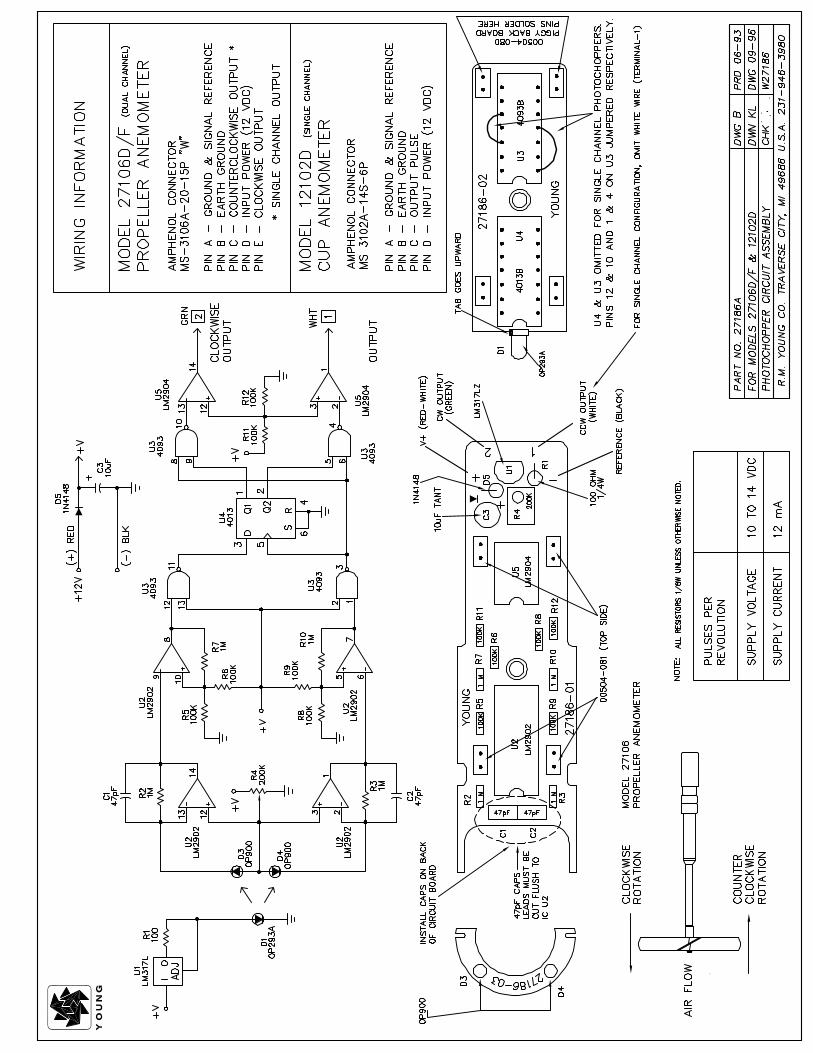
Using the WIRING DIAGRAM as a guide, connect the instrument toan oscilloscope or frequency meter and check for proper signalsfrom the sensor. The calibration may be checked using the methodsoutlined in the CALIBRATION section of this manual.
INSTALLATIONGenerally, the instrument should be oriented with the propellerfacing the predominant flow of air being measured. In some casesit is appropriate to orient the instrument so the predominant air flowis perpendicular to the propeller such as in applications measuringthe vertical component of wind. Keep in mind that off-axisresponse increases the effective threshold and distance constant.For vertical measurements mount the instrument so the propellerfaces upward. This helps prevent moisture or dirt from enteringaround the propeller hub and potentially contaminating thebearings.
If the instrument is used to measure high air velocity or left forextended periods without attention, tape the threaded cableconnector collar to eliminate the possibility of loosening fromvibration. The threaded joint between the photochopper and shafthousings may also be taped.
CALIBRATION
Calibration is determined by propeller pitch and the outputfrequency of the photo chopper transducer.
The Model 08254 Carbon Fiber Thermoplastic Propeller has a 30cm/rev pitch. This is equivalent to 0.00500 m/s per rpm and isaccurate to ±1%. Zero offset is insignificant. Formulas for otherunits of measurement appear below.
Information on checking bearing and transducer torque, which canaffect propeller threshold, also appear in the MAINTENANCEsection.
SPECIFICATION SUMMARY
Range: 0 to 35 m/s (80 mph)
Sensor: 20 cm diameter 4-blade helicoidpropeller molded of carbon fiberthermoplastic
Pitch: 30.0 cm air passage per revolution
Distance Constant: 2.1 m (6.9 ft.) for 63% recovery
Threshold Sensitivity: 0.4 m/s (0.8 mph)
Transducer: Optical photochopper
Power Requirement: 10-14 VDC (12mA @ 12 VDC)
Operating Temp: -50 to 50°C (-58 to 122°F)
Transducer Output: Square wave signal with pulseamplitude approximately equal tosupply voltage -2.
Output Frequency: 10 pulses per propeller revolution(0.030 m/s per Hz)
MODEL 27106DTGILL PROPELLERANEMOMETER

Page 2
When the propeller is used for measuring vertical wind component,users may want to apply a 1.25 multiplier to the output signal. Thismay be done numerically in data processing operations orelectronically in the signal conditioning. Using the multiplier bringsthe anemometer output signal within ±3% of the cosine responsefor elevation angles between -30 and +30 degrees. Since thestandard deviation of wind elevation angle in open terrain rarelyexceeds 12 degrees, 98% (2.5 standard deviations) ofobservations will be within ±30 degrees. Using the multiplier is NOTnecessary when the anemometer is used in a UVW configurationwith YOUNG Model 26700 Programmable Translator.
CALIBRATION FORMULAS
Model 27106DT Propeller anemometer photo chopperw / 08254 Propeller
WIND SPEED vs PROPELLER RPMm/s = 0.00500 x rpmknots = 0.00971 x rpmmph = 0.01118 x rpmkm/h = 0.01800 x rpm
WIND SPEED vs OUTPUT FREQUENCYm/s = 0.03000 x Hzknots = 0.05826 x Hzmph = 0.06708 x Hzkm/h = 0.10800 x Hz
MAINTENANCEGiven proper care the Gill Propeller Anemometer should provideyears of service. Components are conservatively rated andrequire little maintenance. The only parts likely to need replacementdue to normal wear are the precision ball bearings. Thereplacement procedures are best performed in a service facilityand only by qualified technicians. If service facilities are notavailable return the instrument to the factory.
Refer to the accompanying drawings to become familiar with partnames and locations.
FLANGE BEARING REPLACEMENT
If anemometer bearings become noisy or wind speed thresholdincreases above an acceptable level, bearings may needreplacement. Check bearing condition using a Model 18310Anemometer Bearing Torque Disk. If, after replacing bearings, thetorque is still too high, check the photo chopper transducer for anymisalignment.
Replace bearings as follows:
1. REMOVE OLD BEARINGSa) Remove propeller from anemometer.b) Unthread 27153A generator housing threaded collar.c) Unthread generator housing from shaft housing.d) Remove 3-48 screw securing photochopper circuit board
to photochopper mounting.e) Remove 4-40 screw securing window disk to photo disk
hub.f ) Loosen set screw on photo disk hub and remove from
propeller shaft.g) Pull front bearing dust shield off housing.h) Using the edge of a pocket knife, gently pry front and rear
bearings out of housing.
2. INSTALL NEW BEARINGSa) Gently insert front bearing into housing.b) Push front bearing dust shield back onto housing.c) Carefully slide propeller shaft through front bearing and
into housing.d) Slide rear bearing over propeller shaft and gently push it
into housing.e) Place photo disk hub on propeller shaft.f ) Allow 0.010 inch (0.25 mm) end play gap between shaft
collar/coupling disk and bearing. Tighten set screw (80 ozin, 5600 gm-cm max torque).
9) Re-assemble in reverse order as stated in step 1.h) Check bearing torque to confirm it is within specifications.
ADDITIONAL REFERENCES
References containing additional information about the Gill PropellerAnemometer are listed below in chronological order:
Holmes, R. M., Gill, G. C., and Carson, H. W., “A Propeller TypeVertical Anemometer”, Journal of Applied Meteorology, Vol 3,1964, pp. 802-804.
Drinkow, R., “A Solution to the Paired Gill-Anemometer ResponseFunction”, Journal of Applied Meteorology, Vol 11, 1972,pp. 7-80.
Hicks, B. B., “Propeller Anemometers as Sensors of AtmosphericTurbulence”, Boundary-Layer Meteorology, Vol 3,1972,pp. 214-228.
Fichtl, G. H., and Kumar, P., “The Response of PropellerAnemometer to Turbulent Flow with the Mean Wind VectorPerpendicular to the Axis of Rotation”, Boundary-LayerMeteorology, Vol 6,1974, pp. 363-379.
McMichael, J. M., and Klebanoff, P. S., “The Dynamic Response ofHelicoid Anemometers”, NBSIR 75-772, National Bureau ofStandards, 1975.

jim
D08234R.PDF


![System with Metal Lever Handleassets.waterworks.com/wasset/25/original/62025.pdf · LEVER HANDLE SET SCREW x 3 2.5mm HEX [LOOSEN ONLY] 1. THERMOSTATIC HANDLE: LIMIT STOP: Unthread](https://static.fdocuments.us/doc/165x107/607945229c702e6b145ba7c6/system-with-metal-lever-lever-handle-set-screw-x-3-25mm-hex-loosen-only-1-thermostatic.jpg)