Model 2512 Instruction Manual · 2017-08-09 · Model 2512 TSURUGA ELECTRIC CORPORATION 1...
20
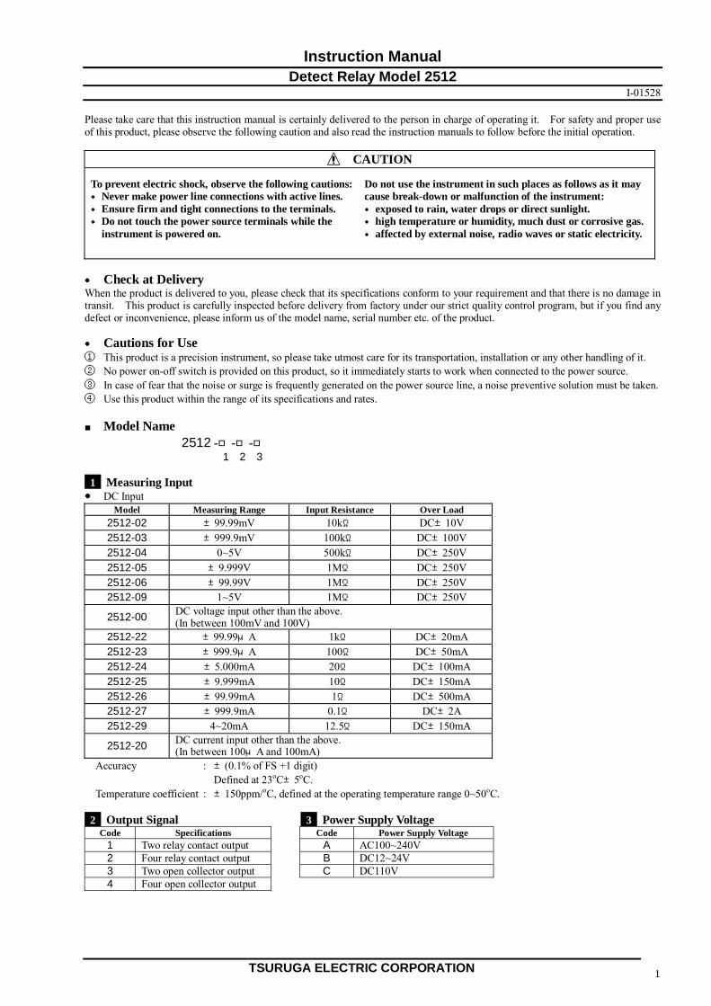
TSURUGA ELECTRIC CORPORATION 1 Instruction Manual Detect Relay Model 2512 I-01528 Please take care that this instruction manual is certainly delivered to the person in charge of operating it. For safety and proper use of this product, please observe the following caution and also read the instruction manuals to follow before the initial operation. CAUTION To prevent electric shock, observe the following cautions: Do not use the instrument in such places as follows as it may ◆ Never make power line connections with active lines. cause break-down or malfunction of the instrument: ◆ Ensure firm and tight connections to the terminals. ◆ exposed to rain, water drops or direct sunlight. ◆ Do not touch the power source terminals while the ◆ high temperature or humidity, much dust or corrosive gas. instrument is powered on. ◆ affected by external noise, radio waves or static electricity. ● Check at Delivery When the product is delivered to you, please check that its specifications conform to your requirement and that there is no damage in transit. This product is carefully inspected before delivery from factory under our strict quality control program, but if you find any defect or inconvenience, please inform us of the model name, serial number etc. of the product. ● Cautions for Use ① This product is a precision instrument, so please take utmost care for its transportation, installation or any other handling of it. ② No power on-off switch is provided on this product, so it immediately starts to work when connected to the power source. ③ In case of fear that the noise or surge is frequently generated on the power source line, a noise preventive solution must be taken. ④ Use this product within the range of its specifications and rates. ■ Model Name 2512 -□-□-□ 1 2 3 1 Measuring Input ● DC Input Model Measuring Range Input Resistance Over Load 2512-02 ±99.99mV 10kΩ DC±10V 2512-03 ±999.9mV 100kΩ DC±100V 2512-04 0~5V 500kΩ DC±250V 2512-05 ±9.999V 1MΩ DC±250V 2512-06 ±99.99V 1MΩ DC±250V 2512-09 1~5V 1MΩ DC±250V 2512-00 DC voltage input other than the above. (In between 100mV and 100V) 2512-22 ±99.99μA 1kΩ DC±20mA 2512-23 ±999.9μA 100Ω DC±50mA 2512-24 ±5.000mA 20Ω DC±100mA 2512-25 ±9.999mA 10Ω DC±150mA 2512-26 ±99.99mA 1Ω DC±500mA 2512-27 ±999.9mA 0.1Ω DC±2A 2512-29 4~20mA 12.5Ω DC±150mA 2512-20 DC current input other than the above. (In between 100μA and 100mA) Accuracy : ±(0.1% of FS +1 digit) Defined at 23 o C±5 o C. Temperature coefficient : ±150ppm/ o C, defined at the operating temperature range 0~50 o C. 2 Output Signal 3 Power Supply Voltage Code Specifications Code Power Supply Voltage 1 Two relay contact output A AC100~240V 2 Four relay contact output B DC12~24V 3 Two open collector output C DC110V 4 Four open collector output
Transcript of Model 2512 Instruction Manual · 2017-08-09 · Model 2512 TSURUGA ELECTRIC CORPORATION 1...
Model 2512
TSURUGA ELECTRIC CORPORATION 1
Instruction Manual Detect Relay Model 2512
I-01528 Please take care that this instruction manual is certainly delivered to the person in charge of operating it. For safety and proper use of this product, please observe the following caution and also read the instruction manuals to follow before the initial operation.
CAUTION
To prevent electric shock, observe the following cautions: Do not use the instrument in such places as follows as it may ◆ Never make power line connections with active lines. cause break-down or malfunction of the instrument: ◆ Ensure firm and tight connections to the terminals. ◆ exposed to rain, water drops or direct sunlight. ◆ Do not touch the power source terminals while the ◆ high temperature or humidity, much dust or corrosive gas. instrument is powered on. ◆ affected by external noise, radio waves or static electricity.
● Check at Delivery When the product is delivered to you, please check that its specifications conform to your requirement and that there is no damage in transit. This product is carefully inspected before delivery from factory under our strict quality control program, but if you find any defect or inconvenience, please inform us of the model name, serial number etc. of the product. ● Cautions for Use ① This product is a precision instrument, so please take utmost care for its transportation, installation or any other handling of it. ② No power on-off switch is provided on this product, so it immediately starts to work when connected to the power source. ③ In case of fear that the noise or surge is frequently generated on the power source line, a noise preventive solution must be taken. ④ Use this product within the range of its specifications and rates. ■ Model Name 2512 -□-□-□ 1 2 3 1 Measuring Input ● DC Input
Model Measuring Range Input Resistance Over Load 2512-02 ±99.99mV 10kΩ DC±10V 2512-03 ±999.9mV 100kΩ DC±100V 2512-04 0~5V 500kΩ DC±250V 2512-05 ±9.999V 1MΩ DC±250V 2512-06 ±99.99V 1MΩ DC±250V 2512-09 1~5V 1MΩ DC±250V
2512-00 DC voltage input other than the above. (In between 100mV and 100V)
2512-22 ±99.99μA 1kΩ DC±20mA 2512-23 ±999.9μA 100Ω DC±50mA 2512-24 ±5.000mA 20Ω DC±100mA 2512-25 ±9.999mA 10Ω DC±150mA 2512-26 ±99.99mA 1Ω DC±500mA 2512-27 ±999.9mA 0.1Ω DC±2A 2512-29 4~20mA 12.5Ω DC±150mA
2512-20 DC current input other than the above. (In between 100μA and 100mA)
Accuracy : ±(0.1% of FS +1 digit) Defined at 23oC±5oC. Temperature coefficient : ±150ppm/oC, defined at the operating temperature range 0~50oC. 2 Output Signal 3 Power Supply Voltage
Code Specifications Code Power Supply Voltage 1 Two relay contact output A AC100~240V 2 Four relay contact output B DC12~24V 3 Two open collector output C DC110V 4 Four open collector output
Model 2512
TSURUGA ELECTRIC CORPORATION 2
■General Specifications Data display : 4 digit, character height 5.5mm Display range -9999~9999 Over-range display When exceed the 130% of the rated input or the display of 9999, is displayed. Decimal point display Settable from the front panel. With zero-suppress function Function No. display : 2 digit, character height 5.5mm Display scaling function : Full scale display -9999~9999 Offset display -9999~9999 Response time : 0.15 sec. or less (90% response, when the moving average function is OFF.) A/D conversion : ∆-Σ conversion system. Noise rejection rate : Normal mode (NMR) 50dB or more Common mode (CMR) 110dB or more Power source line penetrating noise 1000V Comparator range : -9999~9999 Comparison is made to the display. Comparator system : 2 points / 4 points independent setting, arbitrary setting for high and low limit, and comparator output
OFF. CPU comparator judgement system. Comparator condition : Equal NG, equal GO, selectable. Hysteresis width : 1~999, 2 points / 4 points independent setting. Alarm display : Lit up at the alarm output. Output delay : On delay, 0~99 sec. (common for 2 points / 4 points). Power on delay : 2~99 sec. (common for 2 points / 4 points). No alarm is output for two seconds after the power supply is applied. Excitation at alarm : Excitation or non-excitation, selectable. (2 points / 4 points independent setting.) Test mode : ON/OFF of every alarm output can be checked with switch operation. Insulation Resistance : In between Input – Output DC500V 100MΩ or more In between Input/Output – Power Source DC500V 100MΩ or more Terminals in a lump – Housing DC500V 100MΩ or more Withstanding Voltage : In between Input – Output AC2000V for 1 minute In between Input/Output – Power Source AC2000V for 1 minute Terminals in a lump – Housing AC2000V for 1 minute ■Mechanical Specifications Structure : Plug-in type. Connection : Connection by M3 threaded terminal. Isolation : 3 port isolation (in between input, output and power source is isolated). Setting : Program system with front panel switch. ■Specifications of Alarm Output Relay contact output : “1c” contact output each for 2 points, “1a” contact output each for 4 points. Excitation of non-excitation can be set for each relay at the alarm output. (Setting with front panel switch.) Capacity of relay contact : AC250V 1A (resistive load) DC30V 2A (resistive load) Electrical life : 100,000 times (with the load, open/close frequency 1,800 times/h) Mechanical life : 50,000,000 times (with the load, open/close frequency 18,000 times/h) Applicable minimum load : DC5V 10mA Open collector output : NPN type (isolated from input circuit). Output capacity DC50V 100mA ■Specifications for Installation Power source voltage : AC100~240V 50/60Hz DC12~24V DC110V Tolerance of source voltage : AC90~250V DC9~32V DC90~170V Power consumption : For AC power source AC100V approx. 3VA AC200V approx. 4.5VA For DC power source DC12V approx. 100mA DC24V approx. 50mA DC110V approx. 12mA Operating temperature : 0~50 oC Operating humidity : 30~90%RH (with no dew condensation) Weight : Approx. 180g (including the appropriate socket of approx. 40g) Accessory : Appropriate socket (attachable to DIN rail).
Model 2512
TSURUGA ELECTRIC CORPORATION 3
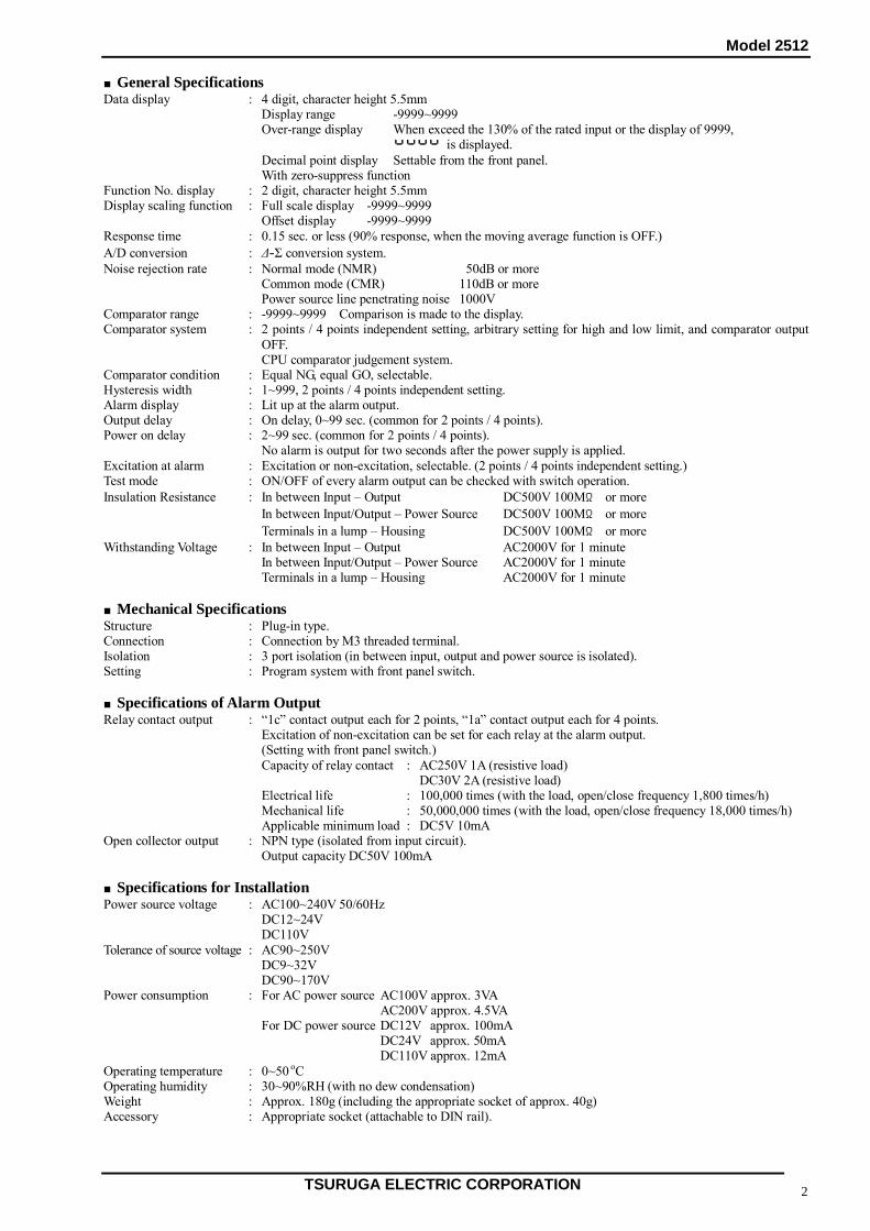
■Dimensions for Installation ■Installation Mount or fix with M4 screws the attached socket on to the DIN rail of 35mm wide. After completed the wiring work, attach and fix the product with the fixing screws to the socket. When removing the product from the socket, unfasten the fixing screws and pull out the product from the socket. Optimum fixing torque: Socket’s fixing screws : 1.1~1.5N・m Product’s fixing screws : 0.1~0.14N・m ■Connection The terminals of the measuring input, alarm output and power supply of this product is M3 screw. Make firm and correct connections by using crimp type terminal or equivalent. Optimum torque of the terminal screws : 0.46~0.62N・m ●Measuring input terminal (INPUT) ⑪, ⑫ Make the connection with correct polarity. Keep the distance for the cabling between the measuring input line and the power source line or output line. If the measuring input line and the power source line or output line are cabled in parallel, it may cause malfunction. ●Alarm output terminal (OUTPUT) ①, ②, ③, ④, ⑤, ⑧, ⑬, ⑭ ① Relay contact output
Make the writing with the cable to meet the contact capacity. In case that the relay control of the capacity higher than the contact is necessary, please provide and auxiliary relay externally.
② Open collector output
Make the writing with the cable to meet the contact capacity. When the alarm is output, the transistor works and ON is made in between C-E. It is isolated from the input circuit.
Socket’s terminal numbers (For the terminal arrangement, please refer to the article of “Installation”.) ●Power supply terminal (POWER SUPPLY) ⑥, ⑦ ① AC power supply specifications Make the connection to the power supply terminal. ②DC power supply specifications Make the connection to the power supply terminal with the polarity.
Input terminal
+ -
terminal
14 12 11 10 9 13
2 1567834
Power source
262 or more
32 or more
2-φ4.2
(or tapped M4)
Unit:mm
32 or more
8 7 6 5
+ -
8 7 6 5
U V
12 11
+ -
12
11
7
6
13
14
1
3
8
4
5
2+
- S1
S2
b contact
a contact
Common 1
Common 2
U(+)
V(-)
2 points relay contact output
12
11
7
6
13
14
1
3
8
4
5
2+
-
S2
U(+)
V(-)
4 points relay contact output
S3
Contact
S1
S4Common 4
Contact
Common 1
Common 3
Common 2
Alarm 1
Alarm 2
Alarm 3
12
11
7
6
13
14
1
3
8
4
5
2+
- S1
S2 Collector
Emitter
U(+)
V(-)
2 points open collector output
12
11
7
6
13
14
1
3
8
4
5
2+
-
U(+)
V(-)
4 points open collector output
S3
S1
S2S4
Alarm 2
Collector
Emitter
Alarm 1
Collector
Emitter
Collector
Emitter
Emitter
Collector
Collector
EmitterAlarm 4
b contact
a contact a contact
a contact
a contact
a contact
Alarm 1
Alarm 2
Alarm 3
Alarm 2
Alarm 1
Alarm 4
Model 2512
TSURUGA ELECTRIC CORPORATION 4
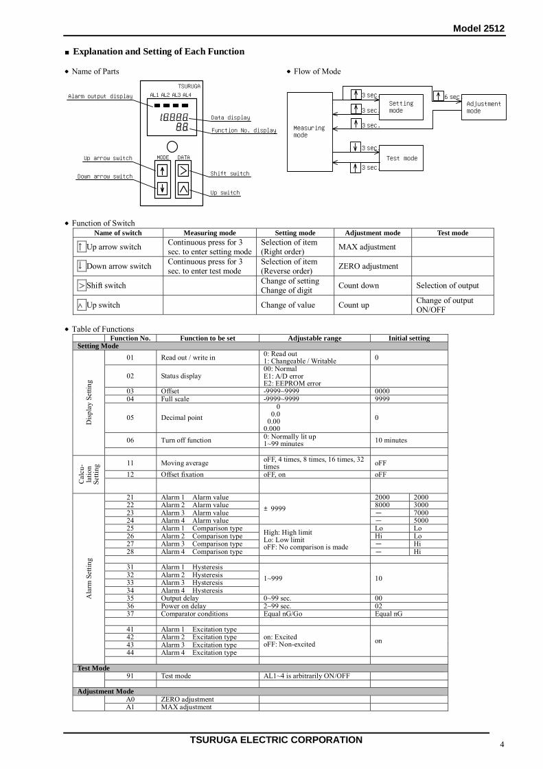
■Explanation and Setting of Each Function ●Name of Parts ●Flow of Mode ●Function of Switch
Name of switch Measuring mode Setting mode Adjustment mode Test mode
↑Up arrow switch Continuous press for 3 sec. to enter setting mode
Selection of item (Right order) MAX adjustment
↓Down arrow switch Continuous press for 3 sec. to enter test mode
Selection of item (Reverse order) ZERO adjustment
>Shift switch Change of setting Change of digit Count down Selection of output
∧Up switch Change of value Count up Change of output ON/OFF
●Table of Functions
Function No. Function to be set Adjustable range Initial setting Setting Mode
01 Read out / write in 0: Read out 1: Changeable / Writable 0
02 Status display 00: Normal E1: A/D error E2: EEPROM error
03 Offset -9999~9999 0000 04 Full scale -9999~9999 9999
05 Decimal point 0.000 000.0 00.00 0.000
0
06 Turn off function 0: Normally lit up 1~99 minutes 10 minutes
Dis
play
Set
ting
11 Moving average oFF, 4 times, 8 times, 16 times, 32
times oFF 12 Offset fixation oFF, on oFF
Cal
cu-
latio
n Se
tting
21 Alarm 1 Alarm value 2000 2000 22 Alarm 2 Alarm value 8000 3000 23 Alarm 3 Alarm value - 7000 24 Alarm 4 Alarm value
±9999 - 5000
25 Alarm 1 Comparison type Lo Lo 26 Alarm 2 Comparison type Hi Lo 27 Alarm 3 Comparison type - Hi 28 Alarm 4 Comparison type
High: High limit Lo: Low limit oFF: No comparison is made
- Hi
31 Alarm 1 Hysteresis 32 Alarm 2 Hysteresis 33 Alarm 3 Hysteresis 34 Alarm 4 Hysteresis
1~999 10
35 Output delay 0~99 sec. 00 36 Power on delay 2~99 sec. 02 37 Comparator conditions Equal nG/Go Equal nG
41 Alarm 1 Excitation type 42 Alarm 2 Excitation type 43 Alarm 3 Excitation type 44 Alarm 4 Excitation type
on: Excited oFF: Non-excited on
Ala
rm S
ettin
g
Test Mode
91 Test mode AL1~4 is arbitrarily ON/OFF Adjustment Mode
A0 ZERO adjustment A1 MAX adjustment
MODE DATA
AL1 AL2 AL3 AL4
TSURUGA
Alarm output display
Up arrow switch
Data display
Function No. display
Shift switch
Up switch
Down arrow switch
Setting
Test mode
Adjustment
Measuring
3 sec. 6 sec.
mode mode
mode
3 sec.
3 sec.
3 sec.
3 sec.

Model 2512
TSURUGA ELECTRIC CORPORATION 5
● Explanation of Functions ○ Setting mode Function No.01 : Read out / write in of the setting To confirm the setting content of the setting mode, select 0. To change the setting content, select 1. Function No.02 : Status display. Faulty symptom of the internal circuit is displayed. When the error is indicated, a certain problem of the product is considered. Please refer to us for the possible cause of the problem or repair. Function No.03 : Display scaling, offset Offset value for the input can be arbitrarily set within the range ‒9999~+9999. Offset value: When the measuring input is ± input 0mV (mA) When the measuring input is 1~5V 1V When the measuring input is 4~20mA 4mA Function No.04 : Display scaling, full scale Display to the max. value of the measuring input can be arbitrarily set within the range ‒9999~+9999. Function No.05 : Decimal point Decimal point can be set at an arbitrary position. Function No.06 : Turn off function
In the measuring mode, this function allows turn off of the data display at the preset time from the finish of switch operation. When 01~99 minutes is set, the display is turned off from the beginning when powered on. When the switch is operated, the display lights up. When the alarm output becomes ON while the display is turned off, the display lights up and afterwards when the alarm output is turned OFF, the display turns off at the preset time.
Function No.11 : Moving average Times for moving average can be set to 4, 8, 16, 32 or nil. Function No.12 : Offset fixation Display of the input value less than the offset value can be fixed to the offset value (function No.3). Function No.21, 22, 23, 24: Alarm value of alarm 1, 2, 3, 4 Comparison value for the alarm output can be set. Function No. 25, 26, 27, 28: Comparison type of alarm 1, 2, 3, 4 “Comparison with high limit, low limit or no comparison” can be selected individually for each alarm output. Function No. 31, 32, 33, 34: Hysteresis Hysteresis width can be set individually for each alarm output. Function No.35 : Output delay
The output delay is an ON delay. The output of high or low limit judgement outgoes after the delay time has passed. The output delay time is common for the alarm 1 to 4.
Function No.36 : Power on delay During the preset time from powering on of the product, the alarm 1 to 4 are not output.
For two seconds from powering on of the product, no alarm is output as it is the initialization time of the internal circuit.
Function No.37 : Comparison condition The comparison condition of the alarm 1 to 4 can be changed to Equal NG or Equal GO. In case of equal NG: Display value≧High limit value・・・・・HI Display value≦Low limit value・・・・・LO In case of equal GO: Display value>High limit value・・・・・HI Display value<Low limit value・・・・・LO Function No. 41, 42, 43, 44: Excitation system of alarm 1, 2, 3, 4 on (excited) ・・・・・・・・・ At alarm, “a” contact of the relay output or the open collector output turns ON. oFF (non-excited) ・・・・ At alarm, “a” contact of the relay output or the open collector output turns OFF. Note: In case of two alarm output type, the function No.23, 24, 27, 28, 33, 34, 43 or 44 is not provided.
Hysteresis width
High limit alarm value
Low limit alarm value
High limit judgement
Low limit judgement
ON
ON
Display value
Model 2512
TSURUGA ELECTRIC CORPORATION 6
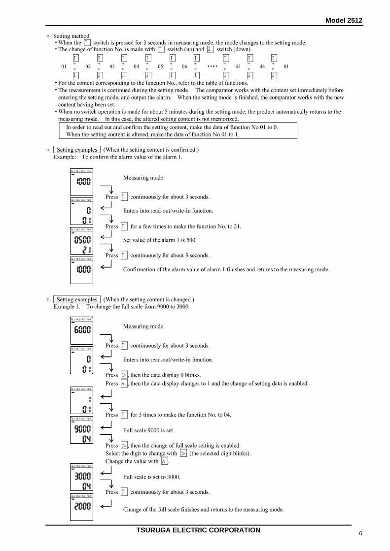
○ Setting method ・ When the ↑ switch is pressed for 3 seconds in measuring mode, the mode changes to the setting mode. ・ The change of function No. is made with ↑ switch (up) and ↓ switch (down).
↑ ↑ ↑ ↑ ↑ ↑ ↑ ↑ ↑ 01 →
←02 →
←03 →
←04 →
←05 →
←06 →
←・・・・ →
←43 →
←44 →
←01
↓ ↓ ↓ ↓ ↓ ↓ ↓ ↓ ↓ ・ For the content corresponding to the function No., refer to the table of functions. ・ The measurement is continued during the setting mode. The comparator works with the content set immediately before
entering the setting mode, and output the alarm. When the setting mode is finished, the comparator works with the new content having been set.
・ When no switch operation is made for about 5 minutes during the setting mode, the product automatically returns to the measuring mode. In this case, the altered setting content is not memorized.
In order to read out and confirm the setting content, make the data of function No.01 to 0. When the setting content is altered, make the data of function No.01 to 1.
○ Setting examples (When the setting content is confirmed.) Example: To confirm the alarm value of the alarm 1. ○ Setting examples (When the setting content is changed.) Example 1: To change the full scale from 9000 to 3000.
AL3 AL4AL1 AL2
AL3 AL4AL1 AL2
Press ↑ continuously for about 3 seconds.
AL3 AL4AL1 AL2
Measuring mode
Enters into read-out/write-in function.
Press ↑ for a few times to make the function No. to 21.
Confirmation of the alarm value of alarm 1 finishes and returns to the measuring mode.
Set value of the alarm 1 is 500.
Press ↑ continuously for about 3 seconds. AL3 AL4AL1 AL2
AL3 AL4AL1 AL2
AL3 AL4AL1 AL2
Press ↑ continuously for about 3 seconds.
AL3 AL4AL1 AL2
Measuring mode
Enters into read-out/write-in function.
Press >, then the data display 0 blinks. Press ∧, then the data display changes to 1 and the change of setting data is enabled.
AL3 AL4AL1 AL2
Press ↑ for 3 times to make the function No. to 04.
Full scale 9000 is set.
AL3 AL4AL1 AL2
Press >, then the change of full scale setting is enabled. Select the digit to change with > (the selected digit blinks). Change the value with ∧.
Press ↑ continuously for about 3 seconds.
Change of the full scale finishes and returns to the measuring mode.
AL3 AL4AL1 AL2
Full scale is set to 3000.
Model 2512
TSURUGA ELECTRIC CORPORATION 7
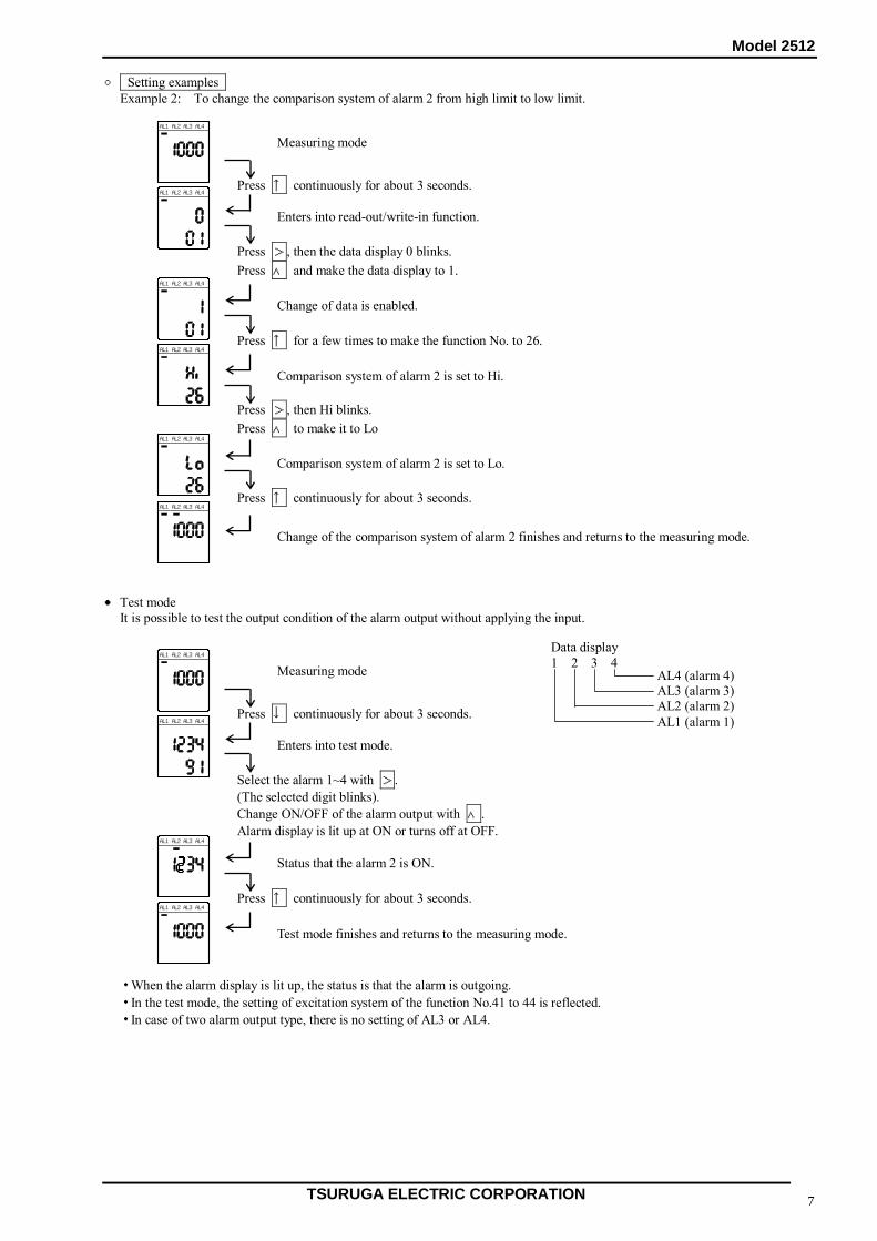
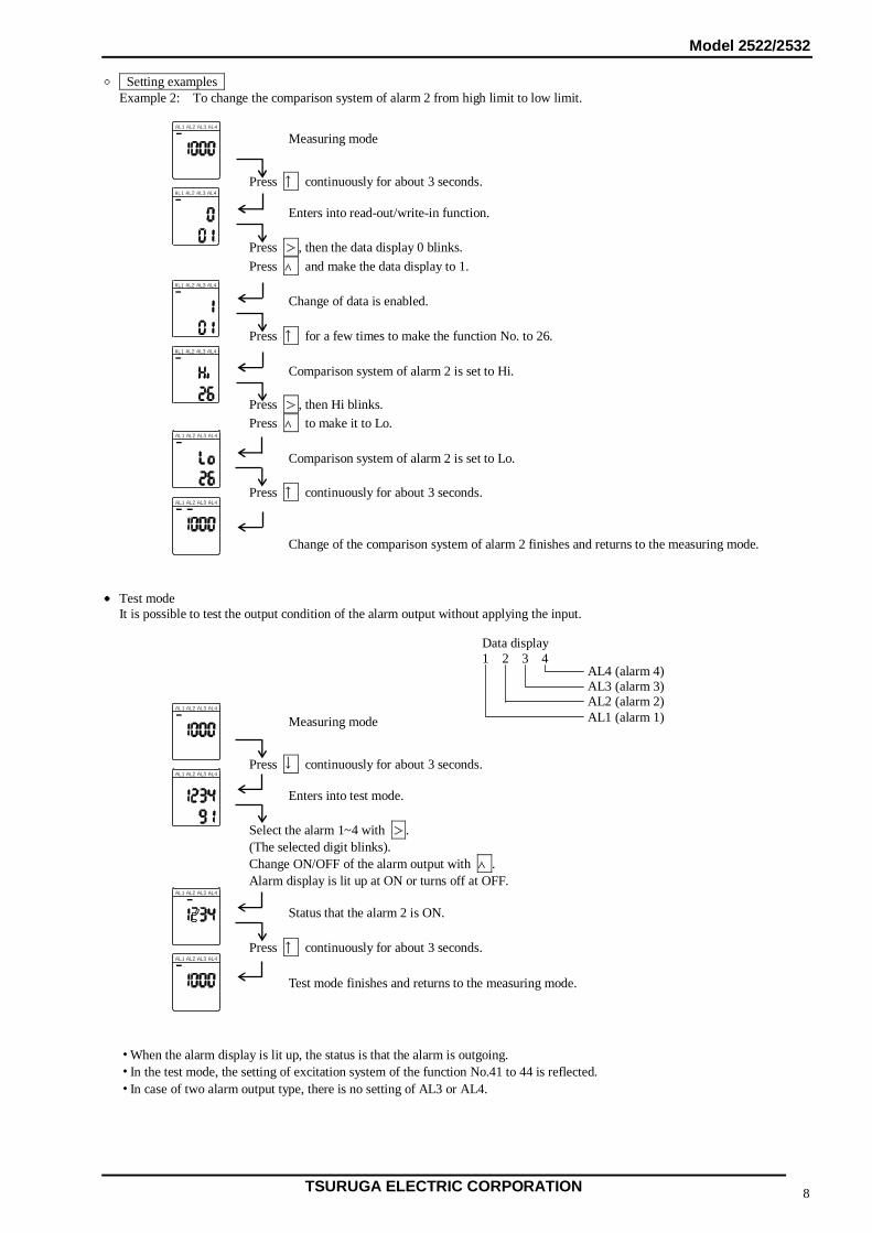
○ Setting examples Example 2: To change the comparison system of alarm 2 from high limit to low limit. ● Test mode It is possible to test the output condition of the alarm output without applying the input. ・ When the alarm display is lit up, the status is that the alarm is outgoing. ・ In the test mode, the setting of excitation system of the function No.41 to 44 is reflected. ・ In case of two alarm output type, there is no setting of AL3 or AL4.
AL3 AL4AL1 AL2
Press ↑ continuously for about 3 seconds.
AL3 AL4AL1 AL2
Measuring mode
Enters into read-out/write-in function.
Press >, then the data display 0 blinks. Press ∧ and make the data display to 1.
AL3 AL4AL1 AL2
Press ↑ for a few times to make the function No. to 26.
Comparison system of alarm 2 is set to Hi.
AL3 AL4AL1 AL2
Press >, then Hi blinks. Press ∧ to make it to Lo
Press ↑ continuously for about 3 seconds.
Change of the comparison system of alarm 2 finishes and returns to the measuring mode.
AL3 AL4AL1 AL2
Comparison system of alarm 2 is set to Lo.
AL3 AL4AL1 AL2
Change of data is enabled.
AL3 AL4AL1 AL2
Press ↓ continuously for about 3 seconds.
AL3 AL4AL1 AL2
Measuring mode
Enters into test mode.
Select the alarm 1~4 with >. (The selected digit blinks). Change ON/OFF of the alarm output with ∧. Alarm display is lit up at ON or turns off at OFF.
AL3 AL4AL1 AL2
Press ↑ continuously for about 3 seconds.
Test mode finishes and returns to the measuring mode.
AL3 AL4AL1 AL2
Status that the alarm 2 is ON.
Data display 1 2 3 4
AL4 (alarm 4) AL3 (alarm 3) AL2 (alarm 2) AL1 (alarm 1)
Model 2512
TSURUGA ELECTRIC CORPORATION 8
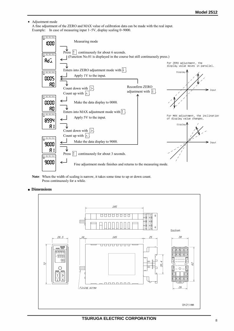
● Adjustment mode A fine adjustment of the ZERO and MAX value of calibration data can be made with the real input. Example: In case of measuring input 1~5V, display scaling 0~9000. Note: When the width of scaling is narrow, it takes some time to up or down count. Press continuously for a while. ■Dimensions
AL3 AL4AL1 AL2
Press ↑ continuously for about 6 seconds.
AL3 AL4AL1 AL2
Measuring mode
(Function No.01 is displayed in the course but still continuously press.)
Count down with >. Count up with ∧.
AL3 AL4AL1 AL2
Enters into MAX adjustment mode with ↑.
AL3 AL4AL1 AL2
Press ↑ continuously for about 3 seconds.
Fine adjustment mode finishes and returns to the measuring mode.
AL3 AL4AL1 AL2
AL3 AL4AL1 AL2
Make the data display to 0000.
Reconfirm ZERO adjustment with ↓.
AL3 AL4AL1 AL2
Enters into ZERO adjustment mode with ↓. Apply 1V to the input.
Apply 5V to the input.
Count down with >. Count up with ∧.
Make the data display to 9000.
105
72
28.5
35.4
2510510
26
62
30
AL3 AL4AL1AL2
MODEL 2512
MODE DATA
Fixing screw
Unit:mm
Socket
Input
Display
For MAX adjustment, the inclinationof display value changes.
Input
Display
For ZERO adjustment, thedisplay value moves in parallel.
Model 2512
TSURUGA ELECTRIC CORPORATION 9
■Maintenance Store the product within the range of specified storage temperature (-20~70 oC). ■Calibration Method To maintain the accuracy over the long time, the calibration at an interval of about one year is recommended. For the calibration method, please refer to the article of adjustment mode.
Model 2522/2532
TSURUGA ELECTRIC CORPORATION 1
Instruction Manual Detect Relay Model 2522/2532
I-01655 Please take care that this instruction manual is certainly delivered to the person in charge of operating it. For safety and proper use of this product, please observe the following caution and also read the instruction manuals to follow before the initial operation.
CAUTION
To prevent electric shock, observe the following cautions: Do not use the instrument in such places as follows as it may ◆ Never make power line connections with active lines. cause break-down or malfunction of the instrument: ◆ Ensure firm and tight connections to the terminals. ◆ exposed to rain, water drops or direct sunlight. ◆ Do not touch the power source terminals while the ◆ high temperature or humidity, much dust or corrosive gas. instrument is powered on. ◆ affected by external noise, radio waves or static electricity.
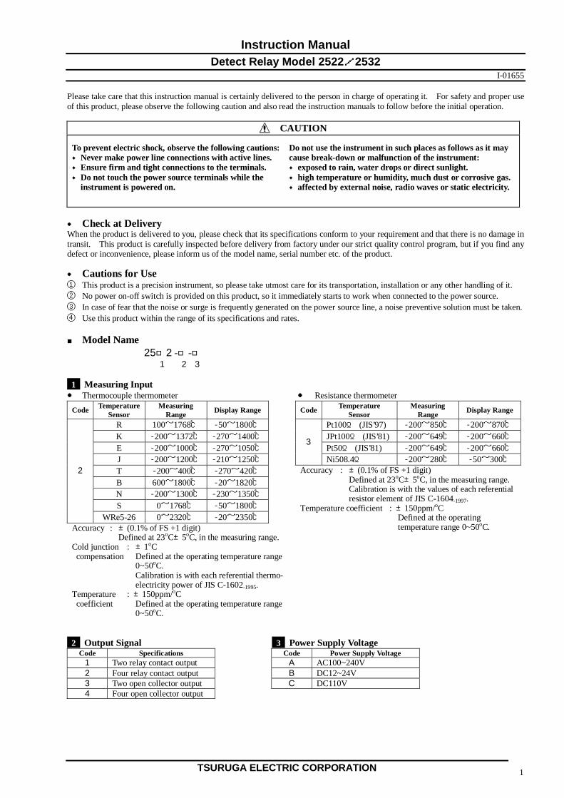
● Check at Delivery When the product is delivered to you, please check that its specifications conform to your requirement and that there is no damage in transit. This product is carefully inspected before delivery from factory under our strict quality control program, but if you find any defect or inconvenience, please inform us of the model name, serial number etc. of the product. ● Cautions for Use ① This product is a precision instrument, so please take utmost care for its transportation, installation or any other handling of it. ② No power on-off switch is provided on this product, so it immediately starts to work when connected to the power source. ③ In case of fear that the noise or surge is frequently generated on the power source line, a noise preventive solution must be taken. ④ Use this product within the range of its specifications and rates. ■ Model Name 25□2 -□-□ 1 2 3 1 Measuring Input ● Thermocouple thermometer ● Resistance thermometer
Code Temperature Sensor
Measuring Range Display Range Code Temperature
Sensor Measuring
Range Display Range
R 100~1768℃ -50~1800℃ Pt100Ω (JIS’97) -200~850℃ -200~870℃K -200~1372℃ -270~1400℃ JPt100Ω (JIS’81) -200~649℃ -200~660℃E -200~1000℃ -270~1050℃ Pt50Ω (JIS’81) -200~649℃ -200~660℃J -200~1200℃ -210~1250℃
3
Ni508.4Ω -200~280℃ -50~300℃ T -200~400℃ -270~420℃ B 600~1800℃ -20~1820℃ N -200~1300℃ -230~1350℃ S 0~1768℃ -50~1800℃
2
WRe5-26 0~2320℃ -20~2350℃ Accuracy : ±(0.1% of FS +1 digit) Defined at 23oC±5oC, in the measuring range. Cold junction : ±1oC compensation Defined at the operating temperature range 0~50oC. Calibration is with each referential thermo- electricity power of JIS C-1602-1995. Temperature : ±150ppm/oC coefficient Defined at the operating temperature range 0~50oC.
Accuracy : ±(0.1% of FS +1 digit) Defined at 23oC±5oC, in the measuring range. Calibration is with the values of each referential resistor element of JIS C-1604-1997. Temperature coefficient : ±150ppm/oC Defined at the operating temperature range 0~50oC.
2 Output Signal 3 Power Supply Voltage
Code Specifications Code Power Supply Voltage 1 Two relay contact output A AC100~240V 2 Four relay contact output B DC12~24V 3 Two open collector output C DC110V 4 Four open collector output
Model 2522/2532
TSURUGA ELECTRIC CORPORATION 2
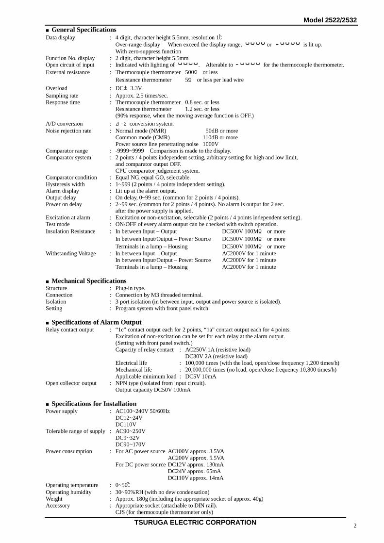
■General Specifications Data display : 4 digit, character height 5.5mm, resolution 1℃ Over-range display When exceed the display range, or is lit up. With zero-suppress function Function No. display : 2 digit, character height 5.5mm Open circuit of input : Indicated with lighting of . Alterable to for the thermocouple thermometer. External resistance : Thermocouple thermometer 500Ω or less Resistance thermometer 5Ω or less per lead wire Overload : DC±3.3V Sampling rate : Approx. 2.5 times/sec. Response time : Thermocouple thermometer 0.8 sec. or less Resistance thermometer 1.2 sec. or less (90% response, when the moving average function is OFF.) A/D conversion : Δ-Σconversion system. Noise rejection rate : Normal mode (NMR) 50dB or more Common mode (CMR) 110dB or more Power source line penetrating noise 1000V Comparator range : -9999~9999 Comparison is made to the display. Comparator system : 2 points / 4 points independent setting, arbitrary setting for high and low limit, and comparator output OFF. CPU comparator judgement system. Comparator condition : Equal NG, equal GO, selectable. Hysteresis width : 1~999 (2 points / 4 points independent setting). Alarm display : Lit up at the alarm output. Output delay : On delay, 0~99 sec. (common for 2 points / 4 points). Power on delay : 2~99 sec. (common for 2 points / 4 points). No alarm is output for 2 sec. after the power supply is applied. Excitation at alarm : Excitation or non-excitation, selectable (2 points / 4 points independent setting). Test mode : ON/OFF of every alarm output can be checked with switch operation. Insulation Resistance : In between Input – Output DC500V 100MΩ or more In between Input/Output – Power Source DC500V 100MΩ or more Terminals in a lump – Housing DC500V 100MΩ or more Withstanding Voltage : In between Input – Output AC2000V for 1 minute In between Input/Output – Power Source AC2000V for 1 minute Terminals in a lump – Housing AC2000V for 1 minute ■Mechanical Specifications Structure : Plug-in type. Connection : Connection by M3 threaded terminal. Isolation : 3 port isolation (in between input, output and power source is isolated). Setting : Program system with front panel switch. ■Specifications of Alarm Output Relay contact output : “1c” contact output each for 2 points, “1a” contact output each for 4 points. Excitation of non-excitation can be set for each relay at the alarm output. (Setting with front panel switch.) Capacity of relay contact : AC250V 1A (resistive load) DC30V 2A (resistive load) Electrical life : 100,000 times (with the load, open/close frequency 1,200 times/h) Mechanical life : 20,000,000 times (no load, open/close frequency 10,800 times/h) Applicable minimum load : DC5V 10mA Open collector output : NPN type (isolated from input circuit). Output capacity DC50V 100mA ■Specifications for Installation Power supply : AC100~240V 50/60Hz DC12~24V DC110V Tolerable range of supply : AC90~250V DC9~32V DC90~170V Power consumption : For AC power source AC100V approx. 3.5VA AC200V approx. 5.5VA For DC power source DC12V approx. 130mA DC24V approx. 65mA DC110V approx. 14mA Operating temperature : 0~50℃ Operating humidity : 30~90%RH (with no dew condensation) Weight : Approx. 180g (including the appropriate socket of approx. 40g) Accessory : Appropriate socket (attachable to DIN rail). CJS (for thermocouple thermometer only)
Model 2522/2532
TSURUGA ELECTRIC CORPORATION 3
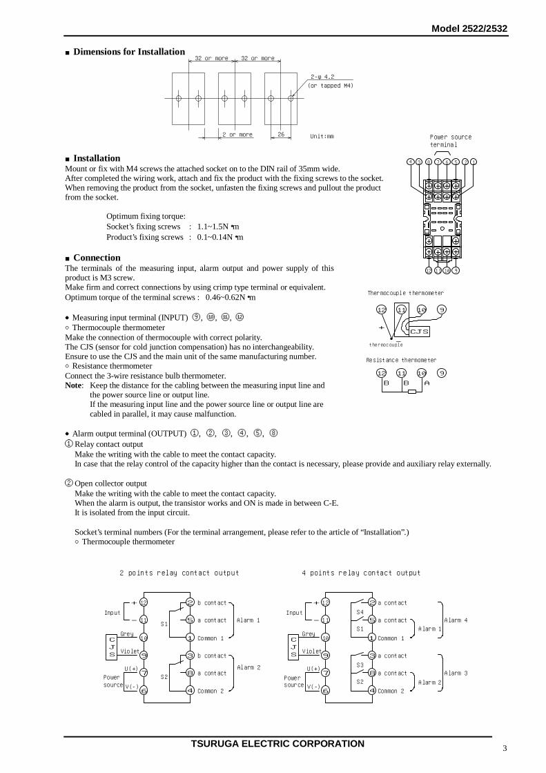
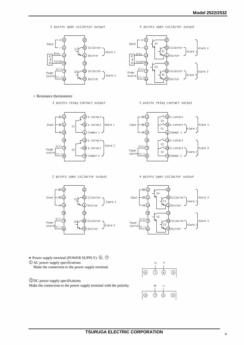
■Dimensions for Installation ■Installation Mount or fix with M4 screws the attached socket on to the DIN rail of 35mm wide. After completed the wiring work, attach and fix the product with the fixing screws to the socket. When removing the product from the socket, unfasten the fixing screws and pullout the product from the socket. Optimum fixing torque: Socket’s fixing screws : 1.1~1.5N・m Product’s fixing screws : 0.1~0.14N・m ■Connection The terminals of the measuring input, alarm output and power supply of this product is M3 screw. Make firm and correct connections by using crimp type terminal or equivalent. Optimum torque of the terminal screws : 0.46~0.62N・m ●Measuring input terminal (INPUT) ⑨, ⑩, ⑪, ⑫ ○Thermocouple thermometer Make the connection of thermocouple with correct polarity. The CJS (sensor for cold junction compensation) has no interchangeability. Ensure to use the CJS and the main unit of the same manufacturing number. ○Resistance thermometer Connect the 3-wire resistance bulb thermometer. Note: Keep the distance for the cabling between the measuring input line and the power source line or output line. If the measuring input line and the power source line or output line are cabled in parallel, it may cause malfunction. ●Alarm output terminal (OUTPUT) ①, ②, ③, ④, ⑤, ⑧ ① Relay contact output Make the writing with the cable to meet the contact capacity. In case that the relay control of the capacity higher than the contact is necessary, please provide and auxiliary relay externally. ② Open collector output Make the writing with the cable to meet the contact capacity. When the alarm is output, the transistor works and ON is made in between C-E. It is isolated from the input circuit. Socket’s terminal numbers (For the terminal arrangement, please refer to the article of “Installation”.) ○Thermocouple thermometer
Power sourceterminal
4 3 8 6 5 2 1
12 11 10 9
7
1112 910
B B A
1112 910
+
-
CJS
Thermocouple thermometer
Resistance thermometer
thermocouple
262 or more
32 or more
2-φ4.2
(or tapped M4)
Unit:mm
32 or more
12
11
10
9
7
6
1
3
8
4
5
2+
-S1
S2
b contact
a contact
Common 1
b contact
a contact
Common 2
Alarm 1
Alarm 2
2 points relay contact output
12
11
1
3
8
4
5
2 a contact
a contact
Common 1
a contact
Common 2
Alarm 1
4 points relay contact output
S1
Alarm 2
Alarm 4
10
9
7
6
Input
CJS
Power
+
-Input
a contact
Alarm 3
S4
S2
S3
Grey
Violet
U(+)
V(-)
CJS
Grey
Violet
U(+)
V(-)sourcePowersource
Model 2522/2532
TSURUGA ELECTRIC CORPORATION 4
○Resistance thermometer ●Power supply terminal (POWER SUPPLY) ⑥, ⑦ ① AC power supply specifications Make the connection to the power supply terminal. ②DC power supply specifications Make the connection to the power supply terminal with the polarity.
568 7
568 7
U V
12
11
1
3
8
4
5
2
S1
S2
Collector
Emitter
Collector
Emitter
Alarm 1
Alarm 2
2 points open collector output
12
11
1
3
8
4
5
2
4 points open collector output
S4
Alarm 2
S1Collector
Emitter
Collector
Emitter
10
9
7
6
10
9
7
6
+
-
+
-
S3
S2
CJS
U(+)
V(-)
CJS
U(+)
V(-)
Input
Power
Grey
Violet
source
Input
Power
Grey
Violet
source
Alarm 1
Alarm 3
Alarm 4
12
11
10
9
7
6
1
3
8
4
5
2B
BS1
S2
b contact
a contact
Common 1
b contact
a contact
Common 2
Alarm 1
Alarm 2
2 points relay contact output 4 points relay contact output
A
Input
12
11
10
9
7
6
Input
1
3
8
4
5
2 a contact
a contact
Common 1
a contact
Common 2
Alarm 1S1
Alarm 2
Alarm 4
a contact
Alarm 3
S4
S2
S3U(+)
V(-)
U(+)
V(-)
B
B
A
Powersource
Powersource
1
3
8
4
5
2
S1
S2
Collector
Emitter
Collector
Emitter
2 points open collector output 4 points open collector output
12
11
10
9
7
6
Input
12
11
10
9
7
6
Input
Alarm 1
Alarm 2
1
3
8
4
5
2S4
Alarm 2
S1Collector
Emitter
Collector
Emitter
S3
S2
Alarm 1
Alarm 4
Alarm 3U(+)
V(-)
U(+)
V(-)
B
B
A
B
B
A
Powersource
Powersource
Model 2522/2532
TSURUGA ELECTRIC CORPORATION 5
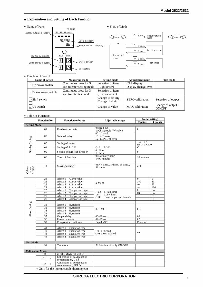
■Explanation and Setting of Each Function ●Name of Parts ●Flow of Mode ●Function of Switch
Name of switch Measuring mode Setting mode Adjustment mode Test mode
↑Up arrow switch Continuous press for 3 sec. to enter setting mode
Selection of item (Right order)
CAL display Display change-over
↓Down arrow switch Continuous press for 3 sec. to enter test mode
Selection of item (Reverse order)
>Shift switch Change of setting Change of digit ZERO calibration Selection of output
∧Up switch Change of value MAX calibration Change of output ON/OFF
●Table of Functions
Initial setting Function No. Function to be set Adjustable range 2 points 4 points Setting Mode
01 Read out / write in 0: Read out 1: Changeable / Writable 0
02 Status display 00: Normal E1: A/D error E2: EEPROM error
03 Setting of sensor TC : K RTD : Pt100
04 Setting of ℃/oF C: ℃ F: oF C 05 Setting of burn-out direction 0 : Plus
1 : Minus 0
06 Turn off function 0: Normally lit up 1~99 minutes 10 minutes
Dis
play
Set
ting
11 Moving average oFF, 4 times, 8 times, 16 times,
32 times oFF
Cal
cu-
latio
n Se
tting
21 Alarm 1 Alarm value 0 0 22 Alarm 2 Alarm value 100 20 23 Alarm 3 Alarm value - 80 24 Alarm 4 Alarm value
±9999 - 100
25 Alarm 1 Comparison type Lo Lo 26 Alarm 2 Comparison type Hi Lo 27 Alarm 3 Comparison type - Hi 28 Alarm 4 Comparison type
High : High limit Lo : Low limit OFF : No comparison is made
- Hi
31 Alarm 1 Hysteresis 32 Alarm 2 Hysteresis 33 Alarm 3 Hysteresis 34 Alarm 4 Hysteresis
001~999 010
35 Output delay 00~99 sec. 00 36 Power on delay 02~99 sec. 02 37 Comparator conditions Equal nG/G Equal nG
41 Alarm 1 Excitation type 42 Alarm 2 Excitation type 43 Alarm 3 Excitation type 44 Alarm 4 Excitation type
On : Excited OFF : Non-excited on
Ala
rm S
ettin
g
Test Mode
91 Test mode AL1~4 is arbitrarily ON/OFF Calibration Mode
C0 ZERO, MAX calibration C1 ※ Calibration of cold junction
compensation, Gain C2 ※ Calibration of cold junction
compensation, ZERO
※Only for the thermocouple thermometer
MODE DATA
AL1 AL2 AL3 AL4
TSURUGA
Alarm output display
Up arrow switch
Data display
Function No. display
Shift switch
Up switch
Down arrow switch
Setting mode
Test mode
Measuring
3 sec.
3 sec.
Calibration5 sec.Power ON
3 sec.
3 sec.
Power OFF
mode
mode
Model 2522/2532
TSURUGA ELECTRIC CORPORATION 6
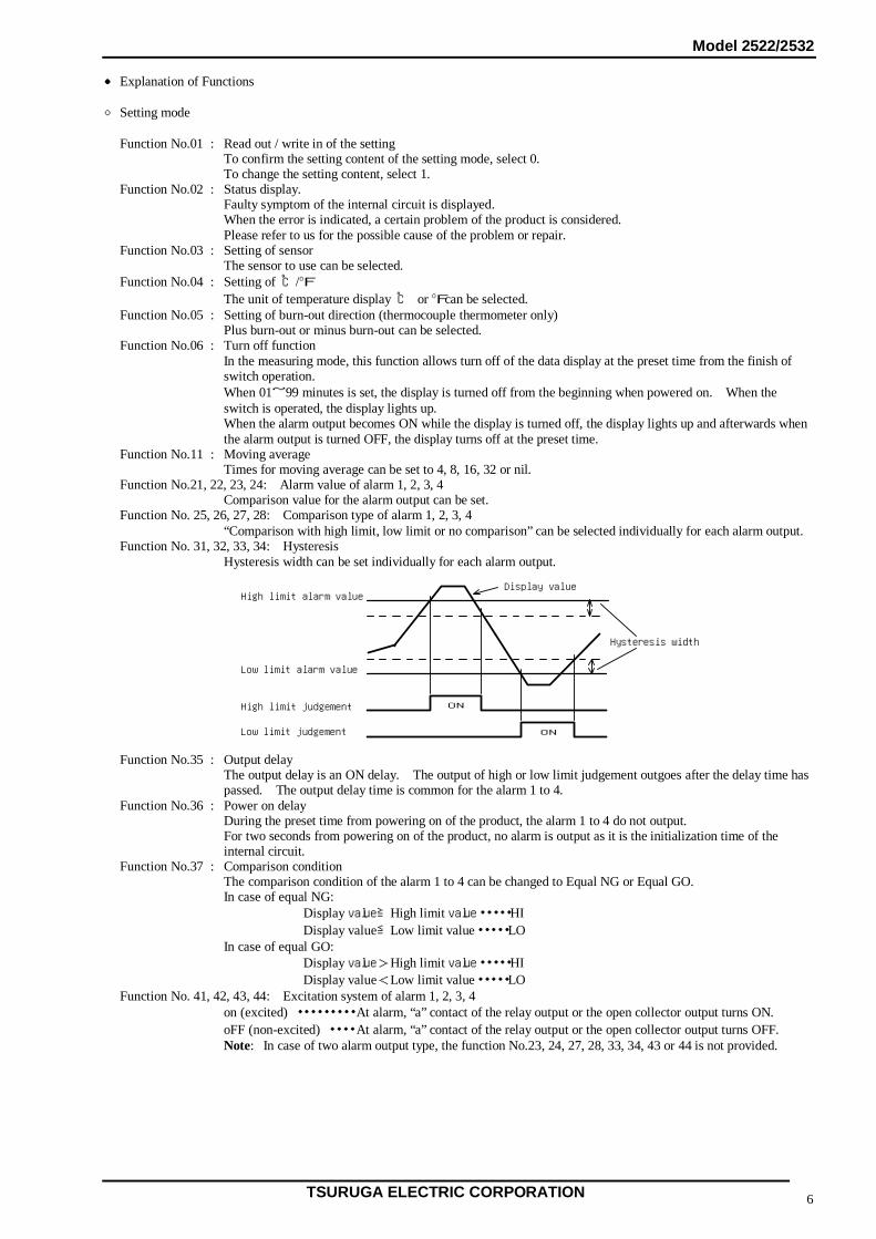
● Explanation of Functions ○ Setting mode Function No.01 : Read out / write in of the setting To confirm the setting content of the setting mode, select 0. To change the setting content, select 1. Function No.02 : Status display. Faulty symptom of the internal circuit is displayed. When the error is indicated, a certain problem of the product is considered. Please refer to us for the possible cause of the problem or repair. Function No.03 : Setting of sensor The sensor to use can be selected. Function No.04 : Setting of ℃/oF The unit of temperature display ℃ or oFcan be selected. Function No.05 : Setting of burn-out direction (thermocouple thermometer only) Plus burn-out or minus burn-out can be selected. Function No.06 : Turn off function
In the measuring mode, this function allows turn off of the data display at the preset time from the finish of switch operation. When 01~99 minutes is set, the display is turned off from the beginning when powered on. When the switch is operated, the display lights up. When the alarm output becomes ON while the display is turned off, the display lights up and afterwards when the alarm output is turned OFF, the display turns off at the preset time.
Function No.11 : Moving average Times for moving average can be set to 4, 8, 16, 32 or nil. Function No.21, 22, 23, 24: Alarm value of alarm 1, 2, 3, 4 Comparison value for the alarm output can be set. Function No. 25, 26, 27, 28: Comparison type of alarm 1, 2, 3, 4 “Comparison with high limit, low limit or no comparison” can be selected individually for each alarm output. Function No. 31, 32, 33, 34: Hysteresis Hysteresis width can be set individually for each alarm output. Function No.35 : Output delay
The output delay is an ON delay. The output of high or low limit judgement outgoes after the delay time has passed. The output delay time is common for the alarm 1 to 4.
Function No.36 : Power on delay During the preset time from powering on of the product, the alarm 1 to 4 do not output.
For two seconds from powering on of the product, no alarm is output as it is the initialization time of the internal circuit.
Function No.37 : Comparison condition The comparison condition of the alarm 1 to 4 can be changed to Equal NG or Equal GO. In case of equal NG: Display value≧High limit value・・・・・HI Display value≦Low limit value・・・・・LO In case of equal GO: Display value>High limit value・・・・・HI Display value<Low limit value・・・・・LO Function No. 41, 42, 43, 44: Excitation system of alarm 1, 2, 3, 4 on (excited) ・・・・・・・・・ At alarm, “a” contact of the relay output or the open collector output turns ON. oFF (non-excited) ・・・・ At alarm, “a” contact of the relay output or the open collector output turns OFF. Note: In case of two alarm output type, the function No.23, 24, 27, 28, 33, 34, 43 or 44 is not provided.
Hysteresis width
High limit alarm value
Low limit alarm value
High limit judgement
Low limit judgement
ON
ON
Display value
Model 2522/2532
TSURUGA ELECTRIC CORPORATION 7
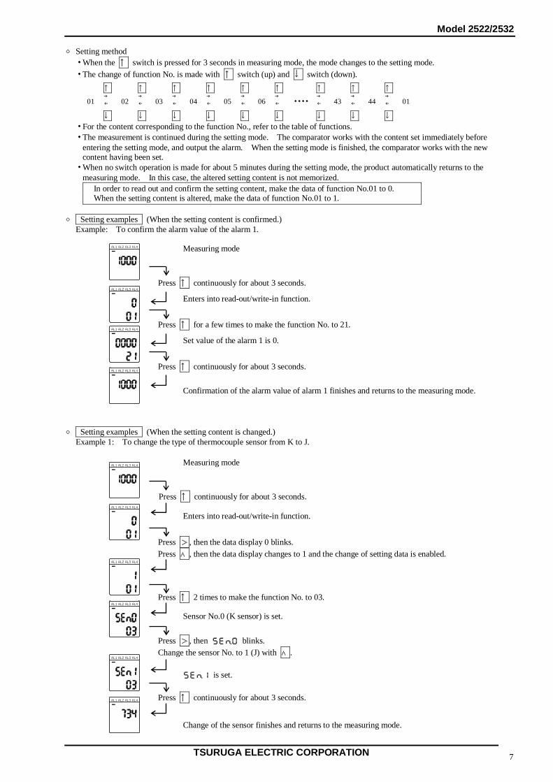
○ Setting method ・ When the ↑ switch is pressed for 3 seconds in measuring mode, the mode changes to the setting mode. ・ The change of function No. is made with ↑ switch (up) and ↓ switch (down).
↑ ↑ ↑ ↑ ↑ ↑ ↑ ↑ ↑
01 → ← 02 →
← 03 → ← 04 →
← 05 →← 06 →
← ・・・・→← 43 →
← 44 → ← 01
↓ ↓ ↓ ↓ ↓ ↓ ↓ ↓ ↓ ・ For the content corresponding to the function No., refer to the table of functions. ・ The measurement is continued during the setting mode. The comparator works with the content set immediately before
entering the setting mode, and output the alarm. When the setting mode is finished, the comparator works with the new content having been set.
・ When no switch operation is made for about 5 minutes during the setting mode, the product automatically returns to the measuring mode. In this case, the altered setting content is not memorized.
In order to read out and confirm the setting content, make the data of function No.01 to 0. When the setting content is altered, make the data of function No.01 to 1.
○ Setting examples (When the setting content is confirmed.)
Example: To confirm the alarm value of the alarm 1. ○ Setting examples (When the setting content is changed.) Example 1: To change the type of thermocouple sensor from K to J.
Confirmation of the alarm value of alarm 1 finishes and returns to the measuring mode.
Measuring mode
Enters into read-out/write-in function.
Press ↑ continuously for about 3 seconds.
Press ↑ for a few times to make the function No. to 21.
Press ↑ continuously for about 3 seconds.
Set value of the alarm 1 is 0.
Measuring mode
Press ↑ continuously for about 3 seconds.
Enters into read-out/write-in function.
Sensor No.0 (K sensor) is set.
Press >, then blinks. Change the sensor No. to 1 (J) with ∧.
Change of the sensor finishes and returns to the measuring mode.
Press ↑ continuously for about 3 seconds.
is set.
Press ↑ 2 times to make the function No. to 03.
Press >, then the data display 0 blinks. Press ∧, then the data display changes to 1 and the change of setting data is enabled.
AL2 AL3 AL4AL1
AL2 AL3 AL4AL1
AL2 AL3 AL4AL1
AL2 AL3 AL4AL1
AL2 AL3 AL4AL1
AL2 AL3 AL4AL1
AL2 AL3 AL4AL1
AL2 AL3 AL4AL1
AL2 AL3 AL4AL1
AL2 AL3 AL4AL1
Model 2522/2532
TSURUGA ELECTRIC CORPORATION 8
○ Setting examples Example 2: To change the comparison system of alarm 2 from high limit to low limit. ● Test mode It is possible to test the output condition of the alarm output without applying the input. ・ When the alarm display is lit up, the status is that the alarm is outgoing. ・ In the test mode, the setting of excitation system of the function No.41 to 44 is reflected. ・ In case of two alarm output type, there is no setting of AL3 or AL4.
Press ↑ continuously for about 3 seconds.
Measuring mode
Enters into read-out/write-in function.
Press >, then the data display 0 blinks. Press ∧ and make the data display to 1.
Press ↑ for a few times to make the function No. to 26.
Comparison system of alarm 2 is set to Hi.
Press >, then Hi blinks. Press ∧ to make it to Lo.
Press ↑ continuously for about 3 seconds.
Change of the comparison system of alarm 2 finishes and returns to the measuring mode.
Comparison system of alarm 2 is set to Lo.
Change of data is enabled.
Data display 1 2 3 4
AL4 (alarm 4) AL3 (alarm 3) AL2 (alarm 2) AL1 (alarm 1)
Press ↓ continuously for about 3 seconds.
Measuring mode
Enters into test mode.
Select the alarm 1~4 with >. (The selected digit blinks). Change ON/OFF of the alarm output with ∧. Alarm display is lit up at ON or turns off at OFF.
Press ↑ continuously for about 3 seconds.
Test mode finishes and returns to the measuring mode.
Status that the alarm 2 is ON.
AL2 AL3 AL4AL1
AL2 AL3 AL4AL1
AL2 AL3 AL4AL1
AL2 AL3 AL4AL1
AL2 AL3 AL4AL1
AL2 AL3 AL4AL1
AL2 AL3 AL4AL1
AL2 AL3 AL4AL1
AL2 AL3 AL4AL1
AL2 AL3 AL4AL1
Model 2522/2532
TSURUGA ELECTRIC CORPORATION 9
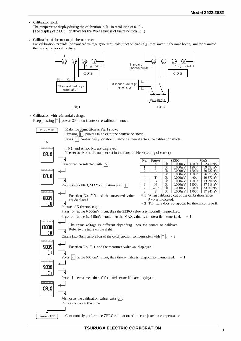
● Calibration mode The temperature display during the calibration is ℃ in resolution of 0.1℃. (The display of 2000℃ or above for the WRe senor is of the resolution 1℃.) ○ Calibration of thermocouple thermometer
For calibration, provide the standard voltage generator, cold junction circuit (put ice water in thermos bottle) and the standard thermocouple for calibration.
Fig.1 Fig. 2 ・ Calibration with referential voltage. Keep pressing ↑, power ON, then it enters the calibration mode.
Make the connection as Fig.1 shows. Pressing ↑, power ON to enter the calibration mode. Press ↑ continuously for about 5 seconds, then it enters the calibration mode.
Continuously perform the ZERO calibration of the cold junction compensation
No. Sensor ZERO MAX0 K 0℃ 0.000mV 1300℃ 52.410mV1 J 0℃ 0.000mV 1200℃ 69.553mV2 R 0℃ 0.000mV 1700℃ 20.222mV3 E 0℃ 0.000mV 1000℃ 76.373mV4 T 0℃ 0.000mV 400℃ 20.872mV5 B 0℃ 0.000mV 1800℃ 13.591mV6 N 0℃ 0.000mV 1300℃ 47.513mV7 WRe 0℃ 0.000mV 2000℃ 33.660mV8 S 0℃ 0.000mV 1700℃ 17.947mV※1 When calibrated out of the calibration range,
is indicated. ※2 This item does not appear for the sensor type B.
1112 910
+ -
CJS
Standard voltage
Grey Violet
CU+ CU-
1112 910
+ -
CJS
Grey Violet
CU-
CU+
Ice water 0℃
Standard+ -
thermocouple
generator
Standard voltagegenerator
Powe OFF
and sensor No. are displayed. The sensor No. is the number set in the function No.3 (setting of sensor).
Enters into ZERO, MAX calibration with ↑.
Sensor can be selected with >.
Function No. and the measured value are displayed.
In case of K thermocouple Press > at the 0.000mV input, then the ZERO value is temporarily memorized. Press ∧ at the 52.410mV input, then the MAX value is temporarily memorized. ※1
The input voltage is different depending upon the sensor to calibrate. Refer to the table on the right.
Enters into Gain calibration of the cold junction compensation with ↑. ※2
Function No. and the measured value are displayed.
Press ∧ at the 500.0mV input, then the set value is temporarily memorized. ※1
Press ↑ two times, then and sensor No. are displayed.
Memorize the calibration values with ∧. Display blinks at this time.
Power OFF
AL2 AL3 AL4AL1
AL2 AL3 AL4AL1
AL2 AL3 AL4AL1
AL2 AL3 AL4AL1
AL2 AL3 AL4AL1
AL2 AL3 AL4AL1
AL2 AL3 AL4AL1
Model 2522/2532
TSURUGA ELECTRIC CORPORATION 10
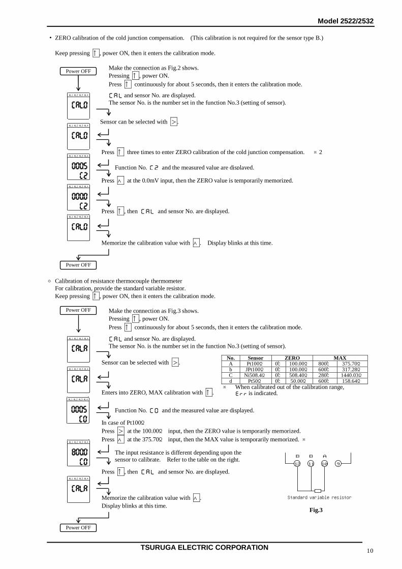
・ ZERO calibration of the cold junction compensation. (This calibration is not required for the sensor type B.) Keep pressing ↑, power ON, then it enters the calibration mode.
Make the connection as Fig.2 shows. Pressing ↑, power ON. Press ↑ continuously for about 5 seconds, then it enters the calibration mode.
○ Calibration of resistance thermocouple thermometer For calibration, provide the standard variable resistor. Keep pressing ↑, power ON, then it enters the calibration mode.
Make the connection as Fig.3 shows. Pressing ↑, power ON. Press ↑ continuously for about 5 seconds, then it enters the calibration mode.
Fig.3
Memorize the calibration value with ∧. Display blinks at this time.
Memorize the calibration value with ∧. Display blinks at this time.
No. Sensor ZERO MAXA Pt100Ω 0℃ 100.00Ω 800℃ 375.70Ωb JPt100Ω 0℃ 100.00Ω 600℃ 317.28ΩC Ni508.4Ω 0℃ 508.40Ω 280℃ 1440.03Ωd Pt50Ω 0℃ 50.00Ω 600℃ 158.64Ω
※ When calibrated out of the calibration range, is indicated.
1112 910
B B
Standard variable resistor
A
Power OFF
Power OFF
AL2 AL3 AL4AL1
and sensor No. are displayed. The sensor No. is the number set in the function No.3 (setting of sensor).
Sensor can be selected with >.
Press ↑ three times to enter ZERO calibration of the cold junction compensation. ※2
Function No. and the measured value are displayed.
Press ∧ at the 0.0mV input, then the ZERO value is temporarily memorized.
Press ↑, then and sensor No. are displayed.
Power OFF
Power OFF
and sensor No. are displayed. The sensor No. is the number set in the function No.3 (setting of sensor).
Sensor can be selected with >.
Enters into ZERO, MAX calibration with ↑.
Function No. and the measured value are displayed.
In case of Pt100Ω Press > at the 100.00Ω input, then the ZERO value is temporarily memorized. Press ∧ at the 375.70Ω input, then the MAX value is temporarily memorized. ※
The input resistance is different depending upon the sensor to calibrate. Refer to the table on the right.
Press ↑, then and sensor No. are displayed.
AL2 AL3 AL4AL1
AL2 AL3 AL4AL1
AL2 AL3 AL4AL1
AL2 AL3 AL4AL1
AL2 AL3 AL4AL1
AL2 AL3 AL4AL1
AL2 AL3 AL4AL1
AL2 AL3 AL4AL1
AL2 AL3 AL4AL1
Model 2522/2532
TSURUGA ELECTRIC CORPORATION 11
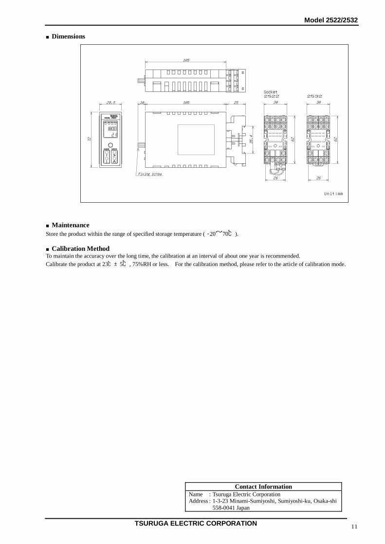
■Dimensions ■Maintenance Store the product within the range of specified storage temperature ( -20~70℃). ■Calibration Method To maintain the accuracy over the long time, the calibration at an interval of about one year is recommended. Calibrate the product at 23℃±5℃, 75%RH or less. For the calibration method, please refer to the article of calibration mode.
105
72
28.5
35.4
2510510
AL3AL4AL1 AL2
MODE DATA
26
62
26
30 30
62
MODEL 2522
Fixing screw
Unit:mm
2522 2532Socket
Contact Information Name : Tsuruga Electric Corporation Address : 1-3-23 Minami-Sumiyoshi, Sumiyoshi-ku, Osaka-shi 558-0041 Japan