Model 2285 EtherBITS™ Universal Single-Port Device … the System console .....24 Using remote...
121
Model 2285 EtherBITS™UniversalSingle-Port Device Server Getting Started Guide Sales Office: +1 (301) 975-1000 Technical Support: +1 (301) 975-1007 E-mail: [email protected] WWW: www.patton.com Document Number: 08313U2-001 Rev. B Part Number: 07M2285-UM Revised: October 8, 2007 Important This is a Class A device and is intended for use in a light industrial environment. It is not intended nor approved for use in an industrial or residential environment.
Transcript of Model 2285 EtherBITS™ Universal Single-Port Device … the System console .....24 Using remote...

Model 2285
EtherBITS™ Universal Single-Port
Device Server
Getting Started Guide
Sales Office:
+1 (301) 975-1000
Technical Support:
+1 (301) 975-1007
E-mail:
WWW:
www.patton.com
Document Number:
08313U2-001 Rev. B
Part Number:
07M2285-UM
Revised:
October 8, 2007
Important
This is a Class A device and is intended for use in a light industrial environment. It is not intended nor approved for use in an industrial or residential environment.

Patton Electronics Company, Inc.
7622 Rickenbacker Drive
Gaithersburg, MD 20879 USA
Tel: +1 (301) 975-1000
Fax: +1 (301) 869-9293
Support: +1 (301) 975-1007
Web: www.patton.com
E-mail: [email protected]
Trademark Statement
EtherBITS is a trademark of Patton Electronics Co..
Copyright © 2007, Patton Electronics Company. All rights reserved.
The information in this document is subject to change without notice. Patton Elec-
tronics assumes no liability for errors that may appear in this document.
Warranty Information
The software described in this document is furnished under a license and may be used
or copied only in accordance with the terms of such license.
Patton Electronics
warrants all EtherBITS™ components to be free from defects, and
will—at our option—repair or replace the product should it fail within one year from
the first date of the shipment.
This warranty is limited to defects in workmanship or materials, and does not cover
customer damage, abuse or unauthorized modification. If the product fails to perform
as warranted, your sole recourse shall be repair or replacement as described above.
Under no condition shall
Patton Electronics
be liable for any damages incurred by the
use of this product. These damages include, but are not limited to, the following: lost
profits, lost savings and incidental or consequential damages arising from the use of or
inability to use this product.
Patton Electronics
specifically disclaims all other warran-
ties, expressed or implied, and the installation or use of this product shall be deemed
an acceptance of these terms by the user.
Note
Conformity documents of all Patton products can be viewed online at
www.patton.com under the appropriate product page.

3
Summary Table of Contents
1 Overview ....................................................................................................................................................... 15
2 Getting started............................................................................................................................................... 19
3 Network configuration .................................................................................................................................. 29
4 Serial port configuration ............................................................................................................................... 44
5 System administration................................................................................................................................... 71
6 System statistics............................................................................................................................................. 80
7 CLI guide ...................................................................................................................................................... 87
8 Contacting Patton for assistance ................................................................................................................... 90
A Compliance information .............................................................................................................................. 93
B Specifications ................................................................................................................................................ 95
C Cable Recommendations .............................................................................................................................. 99
D Configuration files ..................................................................................................................................... 104
E Well-known port numbers ......................................................................................................................... 107
F Guide to the Bios menu program ............................................................................................................... 109
G Using Model 2285 with Serial/IP ............................................................................................................... 116

Contents
Summary Table of Contents ........................................................................................................................... 3
Contents ......................................................................................................................................................... 4
List of Figures ................................................................................................................................................. 8
List of Tables ................................................................................................................................................ 10
About this guide ........................................................................................................................................... 11
Audience............................................................................................................................................................... 11
Structure............................................................................................................................................................... 11
Precautions ........................................................................................................................................................... 12
Safety when working with electricity ...............................................................................................................12
General observations .......................................................................................................................................13
Factory default parameters .................................................................................................................................... 13
Typographical conventions used in this document................................................................................................ 14
General conventions .......................................................................................................................................14
1 Overview ....................................................................................................................................................... 15
Introduction ..........................................................................................................................................................16
Glossary.................................................................................................................................................................17
MAC address ..................................................................................................................................................17
Host ................................................................................................................................................................17
Session ............................................................................................................................................................17
Client/Server ...................................................................................................................................................17
Acronyms ..............................................................................................................................................................18
2 Getting started............................................................................................................................................... 19
Introduction ..........................................................................................................................................................20
Unpacking the Model 2285...................................................................................................................................20
Controls and indicators .........................................................................................................................................20
Connecting the hardware.......................................................................................................................................22
Connecting to the network .............................................................................................................................23
Connecting to the device ................................................................................................................................23
Connecting power ...........................................................................................................................................23
Accessing the System Console................................................................................................................................24
Using the System console ................................................................................................................................24
Using remote console ......................................................................................................................................25
Accessing the web browser management interface..................................................................................................26
3 Network configuration .................................................................................................................................. 29
IP configuration ....................................................................................................................................................30
Using a Static IP Address ................................................................................................................................30
IP address ..................................................................................................................................................31
Subnet mask ..............................................................................................................................................31
Default gateway .........................................................................................................................................31
4

Model 2285 Getting Started Guide
Contents
Primary and Secondary DNS ....................................................................................................................31
Using DHCP ..................................................................................................................................................31
SNMP configurations............................................................................................................................................33
MIB-II System objects Configuration .............................................................................................................33
Access Control Configuration .........................................................................................................................34
Trap Receiver Configuration ...........................................................................................................................34
Management using SNMP ..............................................................................................................................35
Dynamic DNS Configuration ...............................................................................................................................35
SMTP Configuration ............................................................................................................................................37
IP Filtering ............................................................................................................................................................38
Interface ..........................................................................................................................................................38
Option and IP address/mask ...........................................................................................................................39
Service ............................................................................................................................................................39
Chain rule .......................................................................................................................................................39
SYSLOG server configuration................................................................................................................................40
Locating server.......................................................................................................................................................40
Overview .........................................................................................................................................................40
Locating server configuration ..........................................................................................................................41
Locating server communication protocol ........................................................................................................41
NFS server configuration.......................................................................................................................................42
TCP service configuration .....................................................................................................................................42
4 Serial port configuration ............................................................................................................................... 44
Overview ...............................................................................................................................................................45
Serial Port Configuration.......................................................................................................................................47
Port Enable/Disable ........................................................................................................................................48
Port Title ........................................................................................................................................................48
Host Mode Configuration ..............................................................................................................................48
TCP mode ................................................................................................................................................49
UDP mode ................................................................................................................................................53
Modem emulation mode ...........................................................................................................................54
Remote host configuration ..............................................................................................................................58
Cryptography configuration ............................................................................................................................60
Secure Sockets Layer(SSL) cryptography method ......................................................................................60
RC4 cryptography method ........................................................................................................................63
Serial port parameters ......................................................................................................................................63
Modem configuration .....................................................................................................................................67
Port Logging ...................................................................................................................................................68
Port event handling configurations .................................................................................................................69
Event keywords .........................................................................................................................................70
5 System administration................................................................................................................................... 71
Introduction ..........................................................................................................................................................72
System Logging .....................................................................................................................................................72
Change Password...................................................................................................................................................73
5
Model 2285 Getting Started Guide
Contents
Device Name Configuration..................................................................................................................................74
Date and Time Settings .........................................................................................................................................74
Factory Reset .........................................................................................................................................................75
Firmware Upgrade.................................................................................................................................................76
User administration ...............................................................................................................................................79
6 System statistics............................................................................................................................................. 80
Introduction ..........................................................................................................................................................81
Network Interfaces Statistics..................................................................................................................................81
Serial Ports Statistics ..............................................................................................................................................81
IP Statistics .....................................................................................................................................................82
ICMP Statistics .....................................................................................................................................................84
TCP Statistics........................................................................................................................................................85
UDP Statistics .................................................................................................................................................86
7 CLI guide ...................................................................................................................................................... 87
Introduction ..........................................................................................................................................................88
Flash partition .......................................................................................................................................................88
Supported Linux Utilities ......................................................................................................................................88
Shell & shell utilities .......................................................................................................................................88
File and disk utils ............................................................................................................................................88
System utilities ................................................................................................................................................88
Network utilities .............................................................................................................................................88
Accessing CLI........................................................................................................................................................88
8 Contacting Patton for assistance ................................................................................................................... 90
Introduction ..........................................................................................................................................................91
Contact information..............................................................................................................................................91
Patton support headquarters in the USA .........................................................................................................91
Alternate Patton support for Europe, Middle East, and Africa (EMEA) ..........................................................91
Warranty Service and Returned Merchandise Authorizations (RMAs)...................................................................91
Warranty coverage ..........................................................................................................................................91
Out-of-warranty service .............................................................................................................................92
Returns for credit ......................................................................................................................................92
Return for credit policy .............................................................................................................................92
RMA numbers ................................................................................................................................................92
Shipping instructions ................................................................................................................................92
A Compliance information .............................................................................................................................. 93
EMC Compliance .................................................................................................................................................94
Radio and TV Interference (FCC Part 15) ............................................................................................................94
CE Declaration of Conformity ..............................................................................................................................94
Authorized European Representative .....................................................................................................................94
B Specifications ................................................................................................................................................ 95
Serial interface .......................................................................................................................................................96
Network interface ..................................................................................................................................................96
6

Model 2285 Getting Started Guide
Contents
Protocols ...............................................................................................................................................................96
Security .................................................................................................................................................................96
Modem emulation.................................................................................................................................................96
Management .........................................................................................................................................................96
Security .................................................................................................................................................................97
Diagnostic LEDs ...................................................................................................................................................97
Environmental.......................................................................................................................................................97
Physical .................................................................................................................................................................97
Power ....................................................................................................................................................................97
C Cable Recommendations .............................................................................................................................. 99
Ethernet Pin-outs ................................................................................................................................................100
Console and Serial port pin-outs..........................................................................................................................101
Ethernet wiring diagram......................................................................................................................................102
Serial wiring diagram...........................................................................................................................................102
RS-232 serial wiring diagram ........................................................................................................................102
RS-422/485 serial wiring diagram .................................................................................................................103
D Configuration files ..................................................................................................................................... 104
port1.conf............................................................................................................................................................105
filter.conf.............................................................................................................................................................105
snmp.conf............................................................................................................................................................106
E Well-known port numbers ......................................................................................................................... 107
Introduction ........................................................................................................................................................108
F Guide to the Bios menu program ............................................................................................................... 109
Overview .............................................................................................................................................................110
Main menu..........................................................................................................................................................110
RTC configuration menu ....................................................................................................................................110
Hardware test menu ............................................................................................................................................111
A 4.5. Firmware upgrade menu ...........................................................................................................................114
G Using Model 2285 with Serial/IP ............................................................................................................... 116
Model 2285 vs. Serial/IP options.........................................................................................................................117
Connection example—Telnet and SSLv3 encryption ..........................................................................................118
7

List of Figures
1 Factory Reset button location . . . . . . . . . . . . . . . . . . . . . . . . . . . . . . . . . . . . . . . . . . . . . . . . . . . . . . . . . . . . . . 21
2 Ethernet port, Power port, and DIP switch locations . . . . . . . . . . . . . . . . . . . . . . . . . . . . . . . . . . . . . . . . . . . . 21
3 Status LEDs, Serial port, and Console/Data switch locations . . . . . . . . . . . . . . . . . . . . . . . . . . . . . . . . . . . . . . 22
4 Telnet program set up example (TeraTerm Pro) . . . . . . . . . . . . . . . . . . . . . . . . . . . . . . . . . . . . . . . . . . . . . . . . 26
5 Login screen of the Model 2285 web management . . . . . . . . . . . . . . . . . . . . . . . . . . . . . . . . . . . . . . . . . . . . . . 27
6 The Model 2285 web management screen . . . . . . . . . . . . . . . . . . . . . . . . . . . . . . . . . . . . . . . . . . . . . . . . . . . . 28
7 IP configuration . . . . . . . . . . . . . . . . . . . . . . . . . . . . . . . . . . . . . . . . . . . . . . . . . . . . . . . . . . . . . . . . . . . . . . . . 30
8 SNMP Configuration . . . . . . . . . . . . . . . . . . . . . . . . . . . . . . . . . . . . . . . . . . . . . . . . . . . . . . . . . . . . . . . . . . . . 33
9 Browsing MIB-II OIDs of Model 2285 SNMP agent using SNMP Browser (AdventNet MibBrowser) . . . . . . 35
10 Dynamic DNS Configuration . . . . . . . . . . . . . . . . . . . . . . . . . . . . . . . . . . . . . . . . . . . . . . . . . . . . . . . . . . . . . 36
11 SMTP Configurations . . . . . . . . . . . . . . . . . . . . . . . . . . . . . . . . . . . . . . . . . . . . . . . . . . . . . . . . . . . . . . . . . . . 37
12 SMTP mode selection in SMTP configuration . . . . . . . . . . . . . . . . . . . . . . . . . . . . . . . . . . . . . . . . . . . . . . . . . 37
13 IP filtering configuration . . . . . . . . . . . . . . . . . . . . . . . . . . . . . . . . . . . . . . . . . . . . . . . . . . . . . . . . . . . . . . . . . 38
14 IP filtering configuration for each service and serial port . . . . . . . . . . . . . . . . . . . . . . . . . . . . . . . . . . . . . . . . . . 39
15 SYSLOG server configuration . . . . . . . . . . . . . . . . . . . . . . . . . . . . . . . . . . . . . . . . . . . . . . . . . . . . . . . . . . . . . . 40
16 Locating server configuration . . . . . . . . . . . . . . . . . . . . . . . . . . . . . . . . . . . . . . . . . . . . . . . . . . . . . . . . . . . . . . 41
17 NFS server configuration . . . . . . . . . . . . . . . . . . . . . . . . . . . . . . . . . . . . . . . . . . . . . . . . . . . . . . . . . . . . . . . . . 42
18 TCP keep-alive configuration . . . . . . . . . . . . . . . . . . . . . . . . . . . . . . . . . . . . . . . . . . . . . . . . . . . . . . . . . . . . . . 43
19 Serial port configuration main screen . . . . . . . . . . . . . . . . . . . . . . . . . . . . . . . . . . . . . . . . . . . . . . . . . . . . . . . . 47
20 Selecting port parameters . . . . . . . . . . . . . . . . . . . . . . . . . . . . . . . . . . . . . . . . . . . . . . . . . . . . . . . . . . . . . . . . . 47
21 Serial port enable/disable . . . . . . . . . . . . . . . . . . . . . . . . . . . . . . . . . . . . . . . . . . . . . . . . . . . . . . . . . . . . . . . . . 48
22 Port title configuration . . . . . . . . . . . . . . . . . . . . . . . . . . . . . . . . . . . . . . . . . . . . . . . . . . . . . . . . . . . . . . . . . . . 48
23 Host mode configuration (TCP mode) . . . . . . . . . . . . . . . . . . . . . . . . . . . . . . . . . . . . . . . . . . . . . . . . . . . . . . . 49
24 State Transition Diagram of TCP mode . . . . . . . . . . . . . . . . . . . . . . . . . . . . . . . . . . . . . . . . . . . . . . . . . . . . . . 52
25 Host mode configuration (UDP mode) . . . . . . . . . . . . . . . . . . . . . . . . . . . . . . . . . . . . . . . . . . . . . . . . . . . . . . 53
26 Typical case of command/data flow of modem emulation mode . . . . . . . . . . . . . . . . . . . . . . . . . . . . . . . . . . . . 57
27 Host mode configuration (Modem emulation mode) . . . . . . . . . . . . . . . . . . . . . . . . . . . . . . . . . . . . . . . . . . . . 58
28 Remote host configuration . . . . . . . . . . . . . . . . . . . . . . . . . . . . . . . . . . . . . . . . . . . . . . . . . . . . . . . . . . . . . . . . 59
29 Cryptography configuration . . . . . . . . . . . . . . . . . . . . . . . . . . . . . . . . . . . . . . . . . . . . . . . . . . . . . . . . . . . . . . . 60
30 Typical SSL Handshake Process . . . . . . . . . . . . . . . . . . . . . . . . . . . . . . . . . . . . . . . . . . . . . . . . . . . . . . . . . . . . 62
31 RC4 Cryptography configuration . . . . . . . . . . . . . . . . . . . . . . . . . . . . . . . . . . . . . . . . . . . . . . . . . . . . . . . . . . . 63
32 Serial communication type and DIP switch configuration . . . . . . . . . . . . . . . . . . . . . . . . . . . . . . . . . . . . . . . . 64
33 Invalid UART type settings displayed on the Serial port configuration main screen . . . . . . . . . . . . . . . . . . . . . 64
34 Serial parameter configuration . . . . . . . . . . . . . . . . . . . . . . . . . . . . . . . . . . . . . . . . . . . . . . . . . . . . . . . . . . . . . 65
35 Modem configuration . . . . . . . . . . . . . . . . . . . . . . . . . . . . . . . . . . . . . . . . . . . . . . . . . . . . . . . . . . . . . . . . . . . . 67
36 Port logging configuration . . . . . . . . . . . . . . . . . . . . . . . . . . . . . . . . . . . . . . . . . . . . . . . . . . . . . . . . . . . . . . . . 68
37 Port event-handling configurations . . . . . . . . . . . . . . . . . . . . . . . . . . . . . . . . . . . . . . . . . . . . . . . . . . . . . . . . . . 69
38 System status display . . . . . . . . . . . . . . . . . . . . . . . . . . . . . . . . . . . . . . . . . . . . . . . . . . . . . . . . . . . . . . . . . . . . . 72
39 System log configuration and view . . . . . . . . . . . . . . . . . . . . . . . . . . . . . . . . . . . . . . . . . . . . . . . . . . . . . . . . . . 73
40 Changing the password . . . . . . . . . . . . . . . . . . . . . . . . . . . . . . . . . . . . . . . . . . . . . . . . . . . . . . . . . . . . . . . . . . . 73
41 Device name configuration . . . . . . . . . . . . . . . . . . . . . . . . . . . . . . . . . . . . . . . . . . . . . . . . . . . . . . . . . . . . . . . . 74
42 Date and time configuration . . . . . . . . . . . . . . . . . . . . . . . . . . . . . . . . . . . . . . . . . . . . . . . . . . . . . . . . . . . . . . . 74
43 NTP configuration . . . . . . . . . . . . . . . . . . . . . . . . . . . . . . . . . . . . . . . . . . . . . . . . . . . . . . . . . . . . . . . . . . . . . . 75
44 Factory Reset . . . . . . . . . . . . . . . . . . . . . . . . . . . . . . . . . . . . . . . . . . . . . . . . . . . . . . . . . . . . . . . . . . . . . . . . . . 75
45 Firmware upgrade . . . . . . . . . . . . . . . . . . . . . . . . . . . . . . . . . . . . . . . . . . . . . . . . . . . . . . . . . . . . . . . . . . . . . . . 76
46 Transfer binary file by Zmodem (TeraTerm Pro) . . . . . . . . . . . . . . . . . . . . . . . . . . . . . . . . . . . . . . . . . . . . . . . 78
47 Port user administration . . . . . . . . . . . . . . . . . . . . . . . . . . . . . . . . . . . . . . . . . . . . . . . . . . . . . . . . . . . . . . . . . . 79
8

Model 2285 Getting Started Guide
48 Port user configuration . . . . . . . . . . . . . . . . . . . . . . . . . . . . . . . . . . . . . . . . . . . . . . . . . . . . . . . . . . . . . . . . . . . 79
49 Network interfaces statistics . . . . . . . . . . . . . . . . . . . . . . . . . . . . . . . . . . . . . . . . . . . . . . . . . . . . . . . . . . . . . . . 81
50 Serial ports status . . . . . . . . . . . . . . . . . . . . . . . . . . . . . . . . . . . . . . . . . . . . . . . . . . . . . . . . . . . . . . . . . . . . . . . 81
51 IP statistics . . . . . . . . . . . . . . . . . . . . . . . . . . . . . . . . . . . . . . . . . . . . . . . . . . . . . . . . . . . . . . . . . . . . . . . . . . . . 82
52 ICMP Statistics . . . . . . . . . . . . . . . . . . . . . . . . . . . . . . . . . . . . . . . . . . . . . . . . . . . . . . . . . . . . . . . . . . . . . . . . . 84
53 TCP Statistics . . . . . . . . . . . . . . . . . . . . . . . . . . . . . . . . . . . . . . . . . . . . . . . . . . . . . . . . . . . . . . . . . . . . . . . . . . 85
54 UDP Statistics . . . . . . . . . . . . . . . . . . . . . . . . . . . . . . . . . . . . . . . . . . . . . . . . . . . . . . . . . . . . . . . . . . . . . . . . . 86
55 Pin layout of the RJ45 connector . . . . . . . . . . . . . . . . . . . . . . . . . . . . . . . . . . . . . . . . . . . . . . . . . . . . . . . . . . 100
56 Pin layout of the DB-9 connector . . . . . . . . . . . . . . . . . . . . . . . . . . . . . . . . . . . . . . . . . . . . . . . . . . . . . . . . . . 101
57 Serial communication type and DIP switch configuration . . . . . . . . . . . . . . . . . . . . . . . . . . . . . . . . . . . . . . . 101
58 Ethernet direct connection using crossover Ethernet cable . . . . . . . . . . . . . . . . . . . . . . . . . . . . . . . . . . . . . . . 102
59 Ethernet connection using straight through Ethernet cable . . . . . . . . . . . . . . . . . . . . . . . . . . . . . . . . . . . . . . . 102
60 RS-232 wiring diagram . . . . . . . . . . . . . . . . . . . . . . . . . . . . . . . . . . . . . . . . . . . . . . . . . . . . . . . . . . . . . . . . . . 102
61 RS-485 wiring diagram . . . . . . . . . . . . . . . . . . . . . . . . . . . . . . . . . . . . . . . . . . . . . . . . . . . . . . . . . . . . . . . . . . 103
62 RS-422 wiring diagram . . . . . . . . . . . . . . . . . . . . . . . . . . . . . . . . . . . . . . . . . . . . . . . . . . . . . . . . . . . . . . . . . . 103
63 Host mode configuration . . . . . . . . . . . . . . . . . . . . . . . . . . . . . . . . . . . . . . . . . . . . . . . . . . . . . . . . . . . . . . . . 118
64 Cryptography configuration . . . . . . . . . . . . . . . . . . . . . . . . . . . . . . . . . . . . . . . . . . . . . . . . . . . . . . . . . . . . . . 118
65 Select Ports on Serial/IP Control Panel . . . . . . . . . . . . . . . . . . . . . . . . . . . . . . . . . . . . . . . . . . . . . . . . . . . . . . 119
66 Set parameters on Serial/IP Control Panel . . . . . . . . . . . . . . . . . . . . . . . . . . . . . . . . . . . . . . . . . . . . . . . . . . . 120
67 Connect to serial port of Model 2285 via Serial/IP . . . . . . . . . . . . . . . . . . . . . . . . . . . . . . . . . . . . . . . . . . . . . 120
68 Serial/IP Trace Window . . . . . . . . . . . . . . . . . . . . . . . . . . . . . . . . . . . . . . . . . . . . . . . . . . . . . . . . . . . . . . . . . 121
9

10
List of Tables
1 General conventions . . . . . . . . . . . . . . . . . . . . . . . . . . . . . . . . . . . . . . . . . . . . . . . . . . . . . . . . . . . . . . . . . . . . . 14
2 Model 2285 LEDs . . . . . . . . . . . . . . . . . . . . . . . . . . . . . . . . . . . . . . . . . . . . . . . . . . . . . . . . . . . . . . . . . . . . . . 22
3 IP configuration parameters . . . . . . . . . . . . . . . . . . . . . . . . . . . . . . . . . . . . . . . . . . . . . . . . . . . . . . . . . . . . . . . 30
4 Input examples of Option and IP address/mask combination . . . . . . . . . . . . . . . . . . . . . . . . . . . . . . . . . . . . . . 39
5 Serial port configuration parameters . . . . . . . . . . . . . . . . . . . . . . . . . . . . . . . . . . . . . . . . . . . . . . . . . . . . . . . . . 45
6 AT commands supported in the Model 2285 . . . . . . . . . . . . . . . . . . . . . . . . . . . . . . . . . . . . . . . . . . . . . . . . . . 55
7 AT commands Response Code . . . . . . . . . . . . . . . . . . . . . . . . . . . . . . . . . . . . . . . . . . . . . . . . . . . . . . . . . . . . . 56
8 Default value of S-Registers . . . . . . . . . . . . . . . . . . . . . . . . . . . . . . . . . . . . . . . . . . . . . . . . . . . . . . . . . . . . . . . 57
9 Pin assignment of the RJ45 connector for Ethernet . . . . . . . . . . . . . . . . . . . . . . . . . . . . . . . . . . . . . . . . . . . . 100
10 Pin assignment of DB-9 connector for console and serial port . . . . . . . . . . . . . . . . . . . . . . . . . . . . . . . . . . . . 101
11 Well-known port numbers . . . . . . . . . . . . . . . . . . . . . . . . . . . . . . . . . . . . . . . . . . . . . . . . . . . . . . . . . . . . . . . 108
12 Model 2285 vs. Serial/IP option compatibility matrix table . . . . . . . . . . . . . . . . . . . . . . . . . . . . . . . . . . . . . . 117

About this guideThis guide describes installing and configuring a Patton Electronics Model 2285 EtherBITS™ Universal Sin-
gle-Port Device Server. By the time you are finished with this guide, your device server will be fully connected
and able to transfer data.
AudienceThis guide is intended for the following users:
Operators
Installers
Maintenance technicians
StructureThis guide contains the following chapters and appendices:
Chapter 1 on page 15 provides information about device server features and capabilities
Chapter 2 on page 19 describes installing the device server
Chapter 3 on page 29 describes how to set up the network configuration
Chapter 4 on page 44 describes configuring the serial port
Chapter 5 on page 71 describes configuring the system administration
Chapter 6 on page 80 describes using system statistics
Chapter 7 on page 87 describes the CLI
Chapter 8 on page 90 contains information on contacting Patton technical support for assistance
Appendix A on page 93 contains compliance information for the Model 2285 device server
Appendix B on page 95 contains specifications for the device server
Appendix C on page 99 provides cable recommendations
Appendix D on page 104 describes the configuration files
Appendix E on page 107 lists well-known port numbers
Appendix F on page 109 provides a guide to the Bios menu program
Appendix G on page 116 describes using the Model 2285 with Serial/IP
For best results, read the contents of this guide before you install the device server.
11

Model 2285 Getting Started Guide
About this guide
PrecautionsNotes, cautions, and warnings, which have the following meanings, are used throughout this guide to help you
become aware of potential problems. Warnings are intended to prevent safety hazards that could result in per-
sonal injury. Cautions are intended to prevent situations that could result in property damage or
impaired functioning.
Note A note presents additional information or interesting sidelights.
Safety when working with electricity
The alert symbol and IMPORTANT heading calls attention to important information.
The alert symbol and CAUTION heading indicate a potential haz-ard. Strictly follow the instructions to avoid property damage.
The shock hazard symbol and CAUTION heading indicate a potential electric shock hazard. Strictly follow the instructions to avoid property damage caused by electric shock.
The alert symbol and WARNING heading indicate a potential safety hazard. Strictly follow the warning instructions to avoid personal injury.
The shock hazard symbol and WARNING heading indicate a potential electric shock hazard. Strictly follow the warning instructions to avoid injury caused by electric shock.
Do not work on the system or connect or disconnect cables during periods of lightning activity.
For units with an external power adapter, the adapter shall be a listed Lim-ited Power Source.
IMPORTA
CAUTIO
CAUTIO
WARNIN
WARNIN
WARNIN
WARNIN
12

Model 2285 Getting Started Guide
About this guide
General observationsClean the case with a soft slightly moist anti-static cloth
Place the unit on a flat surface and ensure free air circulation
Avoid exposing the unit to direct sunlight and other heat sources
Protect the unit from moisture, vapors, and corrosive liquids
Factory default parametersModel 2285 EtherBITS Universal Single-Port Device Server have the following factory default parameters.
Ethernet IP address: 192.168.161.5
Login: superuser
Password: superuser
Static IP address
Filter: “All services and ports are accessible from any host.”
Serial port: 9600 data rate , 8-bits, no parity, 1 stop bit, no flow control
Hazardous network voltages are present in WAN ports regardless of whether power to the unit is ON or OFF. To avoid electric shock, use caution when near WAN ports. When detaching the cables, detach the end away from the device first.
This device contains no user serviceable parts. The equipment shall be returned to Patton Electronics for repairs, or repaired by qualified service personnel.
In accordance with the requirements of council directive 2002/96/EC on Waste of Electrical and Electronic Equipment (WEEE), ensure that at end-of-life you separate this product from other waste and scrap and deliver to the WEEE collection system in your country for recycling.
WARNIN
WARNIN
13

Model 2285 Getting Started Guide
About this guide
Typographical conventions used in this documentThis section describes the typographical conventions and terms used in this guide.
General conventionsThe procedures described in this manual use the following text conventions:
Table 1. General conventions
Convention Meaning
Garamond blue type Indicates a cross-reference hyperlink that points to a figure, graphic, table, or sec-tion heading. Clicking on the hyperlink jumps you to the reference. When you have finished reviewing the reference, click on the Go to Previous View button in the Adobe® Acrobat® Reader toolbar to return to your starting point.
Futura bold type Commands and keywords are in boldface font.Futura bold-italic type Parts of commands, which are related to elements already named by the user, are
in boldface italic font.Italicized Futura type Variables for which you supply values are in italic fontFutura type Indicates the names of fields or windows.Garamond bold type Indicates the names of command buttons that execute an action.
14

Chapter 1 Overview
Chapter contentsIntroduction ..........................................................................................................................................................16
Glossary.................................................................................................................................................................17
MAC address ..................................................................................................................................................17
Host ................................................................................................................................................................17
Session ............................................................................................................................................................17
Client/Server ...................................................................................................................................................17
Acronyms ..............................................................................................................................................................18
15

Model 2285 Getting Started Guide
1 • Overview
IntroductionThe Model 2285 EtherBITS Universal Single-Port Device Server makes your legacy serial devices manageable
by an industry-standard Ethernet network. Based on open network protocols such as TCP/IP and UDP, it
gives you ultimate flexibility to your serial devices.
With the rich broadband network connectivity protocols such as DHCP and Dynamic DNS, you can manage
legacy serial devices over broadband Internet by using DSL or cable modem connection. The built-in Dynamic
DNS protocol of the Model 2285 enables you to access the serial devices with their own domain names.
The Model 2285 also provides you with the system management functionality of system status display, firm-
ware upgrade, remote reset and system log display by using various ways such as telnet, SSH, serial console port
or web.
You can configure and administrate the Model 2285, with the management functions of status monitor,
remote reset, error log monitor and firmware upgrade by using Telnet and serial console port under the pass-
word secured support.
For critical applications of secure data communication, the Model 2285 supports SSLv3 for data encryption.
In addition, IP address filtering function is provided for protecting unintentional data streams to be transmit-
ted to the Model 2285.
Typical application areas of the Model 2285 are:
• Industrial automation
• Network management
• Retail/Point of sale
• Remote metering
• Remote display
• Building automation
• Security/Access control systems
• General data acquisition application
• Medical application
The Model 2285 gives you ideal remote management capability of control, monitoring, diagnosis and data
gathering over RS232/422/485 serial devices.
Note This manual assumes user knowledge of Internetworking protocols and
serial communications
Introduction 16

Model 2285 Getting Started Guide
1 • Overview
GlossaryThis section defines commonly used terms in this manual. These terms are related to Internetworking, and
defined in regards to their use with Model 2285.
MAC addressOn a local area network or other network, the MAC (Media Access Control) address is the computer’s unique
hardware number. (On an Ethernet LAN, it is the same as the Ethernet address.)
It is a unique 12-digit hardware number, which is composed of 6-digit OUI (Organization Unique Identifier)
number and 6-digit hardware identifier number. The MAC address can be found on the bottom of the
original package.
HostA user’s computer connected to the network
Internet protocol specifications define host as any computer that has full two-way access to other computers on
the Internet. A host will have a specific local or host number that, together with the network number, forms its
unique IP address.
SessionA series of interactions between two communication end points that occur during the span of a
single connection
Typically, one end point requests a connection with another specified end point. If the specified end point
replies, and agrees to the connection, the end points then take turns exchanging commands and data (talking to
each other). The session begins when the connection is established at both ends and terminates when the con-
nection is ended.
Client/ServerClient/server describes the relationship between two computer programs in which one program, the client,
makes a service request from another program, the server, which fulfills the request.
A server is a computer program that provides services to other computer programs on one or many computers.
The client is the requesting program or user in a client/server relationship. For example, the user of a Web
browser is effectively making client requests for pages from servers all over the Web. The browser itself is a cli-
ent in its relationship with the computer that is getting and returning the requested HTML file. The computer
handling the request and sending back the HTML file is a server.
Glossary 17

Model 2285 Getting Started Guide 1 • Overview
Acronyms
Acronym Definition
ISP Internet Service ProviderPC Personal ComputerNIC Network Interface CardMAC Media Access ControlLAN Local Area NetworkUTP Unshielded Twisted Pair
ADSL Asymmetric Digital Subscriber LineARP Address Resolution ProtocolIP Internet Protocol
ICMP Internet Control Message ProtocolUDP User Datagram ProtocolTCP Transmission Control Protocol
DHCP Dynamic Host Configuration ProtocolSMTP Simple Mail Transfer ProtocolFTP File Transfer ProtocolPPP Point-To-Point Protocol
PPPoE Point-To-Point Protocol over EthernetHTTP HyperText Transfer ProtocolDNS Domain Name Service
DDNS Dynamic Domain Name ServiceSNMP Simple Network Management ProtocolRADIUS Remote Access for Dial-In User Service
SSH Secure ShellNTP Network Time ProtocolUART Universal Asynchronous Receiver/TransmitterBps Bits per second (baud rate)DCE Data Communications EquipmentDTE Data Terminal EquipmentCTS Clear to SendDSR Data Set ReadyDTR Data Terminal ReadyRTS Request To SendDCD Data Carrier Detect
Acronyms 18

Chapter 2 Getting started
Chapter contentsIntroduction ..........................................................................................................................................................20
Unpacking the Model 2285...................................................................................................................................20
Controls and indicators .........................................................................................................................................20
Connecting the hardware.......................................................................................................................................22
Connecting to the network .............................................................................................................................23
Connecting to the device ................................................................................................................................23
Connecting power ...........................................................................................................................................23
Accessing the System Console................................................................................................................................24
Using the System console ................................................................................................................................24
Using remote console ......................................................................................................................................25
Accessing the web browser management interface..................................................................................................26
19

Model 2285 Getting Started Guide 2 • Getting started
IntroductionThis chapter describes how to set up and configure the Model 2285.
• “Unpacking the Model 2285”—lists the contents of the device server’s shipping container
• “Controls and indicators”—Explains the layout of the Model 2285 controls and LED indicators
• Accessing the Web Browser Management Interface describes how to access the console port using a serial
console or a Telnet or Web menu from remote location.
The following items are required to get started.
• One power cable (included in the package)
• One Serial data cable (included in the package)
• One Ethernet cable
• One PC with network interface card (hereafter, NIC) and/or one RS-232 serial port.
Unpacking the Model 2285Inspect the shipping carton for external damage. Note any damage before removing the container contents.
Report equipment damage to the shipping carrier immediately for claim purposes. Save all packing materials in
case you need to return an item to the factory for servicing.
The Model 2285 comes with the following items:
• Model 2285 device server
• External 110 VAC (or 230 VAC) power supply
• Serial cable kit
• CD-ROM containing the Serial/IP, EtherBITS Device Manager, Model 2285 Quick Start Guide, and
Model 2285 Getting Started Guide
Controls and indicatorsThe Model 2285 has four LED indicator lamps for status display. Upper-left lamp indicates the system power-
on status. Lower-left lamp indicates the 10/100Base Ethernet Link status. Right two lamps indicate Receive
and Transmit of the serial port.
Introduction 20

Model 2285 Getting Started Guide 2 • Getting started
The Factory Reset button on the underside of the Model 2285 (see figure 1) is used to restore the device server
to the factory default configuration.
Figure 1. Factory Reset button location
The Serial Type DIP switches are used to configure the serial communication port (see figure 2). (Refer to sec-
tion “Serial port parameters” on page 63 and Appendix C on page 99 for more detailed information on the
serial communication type and its connection)
Figure 2. Ethernet port, Power port, and DIP switch locations
Factory
Reset
Factory Reset button
Model 2285
EtherBITS Universal Single-Port Device Server
Serial
PWRLink
TxRx
Console/Data
Power
Ethernet
Serial Type
12
3
ON
Ethernet port
Serial Type DIP switches
Power port
Controls and indicators 21

Model 2285 Getting Started Guide 2 • Getting started
The Console/Data switch (see figure 3) enables a user to set the serial port for console or data mode. (Refer to
section “Accessing the System Console” on page 24 for more information on serial console access)
Figure 3. Status LEDs, Serial port, and Console/Data switch locations
The serial port status LEDs are described in table 2.
Connecting the hardwareThis section describes how to connect the Model 2285 to your equipment for initial testing.
• Connect the Model 2285 to an Ethernet hub or switch
• Connect the device
• Connect the provided power source to the Model 2285
Table 2. Model 2285 LEDs
Lamps Function
Status PWR Turned on to RED if power is suppliedLink Turned on to GREEN if system is connected to Ethernet network.
Serial port Rx Blinks whenever there is any incoming data stream through the serial port of the Model 2285
Tx Blinks whenever there is any outgoing data stream through the serial port of the Model 2285
Model 2285
EtherBITS Universal Single-Port Device Server
Serial
PWR Link
Tx Rx
Console/Data
Power
Ethernet
Serial Type
Serial port
Console/Dswitch
Link LED
PWR LEDRx and TxLEDs
Connecting the hardware 22

Model 2285 Getting Started Guide 2 • Getting started
Connecting to the network
Plug one end of the Ethernet cable to the Model 2285 Ethernet port (see figure 2 on page 21). The other end of
the Ethernet cable should be connected to a network port. If the cable is properly connected, the Model 2285
will have a valid connection to the Ethernet network. This will be indicated by:
• The Link LED will light up green (see figure 3 on page 22)
• The Tx and Rx LEDs will blink to indicate incoming/outgoing Ethernet packets (see figure 3 on page 22)
Connecting to the device
Connect the serial cable to the Model 2285 Serial port (see figure 3 on page 22). To connect to the serial port
of the device, the user needs to consider the type of console port provided by the device itself. Refer to appen-
dix C, “Cable Recommendations” on page 99 for details.
Note If the configuration of the Model 2285 through the serial console is
required, connect the serial cable to the serial port of user’s computer first.
And push the Console/Data switch to the Console side. And also set the posi-
tion of DIP switches (see figure 2 on page 21) for serial mode to RS-232
mode. Configuration of the Model 2285 is discussed in section “Accessing
the System Console” on page 24.
Connecting power
Connect the power cable to the Model 2285 Power port (see figure 2 on page 21). If the power is properly sup-
plied, the PWR LED will light up solid red.
The interconnecting cables shall be acceptable for external use and shall be rated for the proper application with respect to volt-age, current, anticipated temperature, flammability, and mechanical serviceability.
The interconnecting cables shall be acceptable for external use and shall be rated for the proper application with respect to volt-age, current, anticipated temperature, flammability, and mechanical serviceability.
The interconnecting cables shall be acceptable for external use and shall be rated for the proper application with respect to volt-age, current, anticipated temperature, flammability, and mechanical serviceability.
CAUTIO
CAUTIO
CAUTIO
Connecting the hardware 23

Model 2285 Getting Started Guide 2 • Getting started
Accessing the System ConsoleThere are several ways to access the Model 2285. These methods are dependent on whether the user is located
at a local site or a remote site, or whether the user requires a menu-driven interface, graphic menu system or
CLI (Command Line Interface).
• System console: Local users can connect directly to the system console port of the Model 2285 using the
serial console cable.
• Remote console: Remote users who require a menu-driven interface can utilize Telnet (port 23) or SSH
(port 22) connections to the Model 2285 using Telnet or SSH client.
Note The Model 2285 supports only the SSH v2, so user must use the SSH client
which is able to support SSH v2.
• Web: Remote users who want to use a web browser to configure the Model 2285 can connect to the
Model 2285 using a conventional web browser, such as Internet Explorer or Netscape Navigator.
The above methods require user authentication by the Model 2285 system.
Using the System console1. Connect one end of the console cable to the console port on the Model 2285 (see figure 3 on page 22).
2. Push the Console/Data switch to the Console side.
3. Set the position of DIP switch for serial mode to RS-232 mode. Configuration of DIP switch is discussed
in appendix C, “Cable Recommendations” on page 99.
4. Connect the other end of the cable to the serial port of the user’s computer.
5. Run a terminal emulator program (i.e. HyperTerminal). Set the serial configuration parameters of the ter-
minal emulation program as follows:
– 9600 Baud rate
– Data bits 8
– Parity None
– Stop bits 1
– No flow control
6. Press the [ENTER] key.
7. Enter your username and password to log into the Model 2285. The factory default user settings are
as follows.
– Login: superuser
– Password: superuser
The interconnecting cables shall be acceptable for external use and shall be rated for the proper application with respect to volt-age, current, anticipated temperature, flammability, and mechanical serviceability.CAUTIO
Accessing the System Console 24

Model 2285 Getting Started Guide 2 • Getting started
2285 login: root
Password:
#
8. After login, user can use various shell commands in the CLI (command line interface). For details on the
CLI, refer to the chapter 7, “CLI guide” on page 87.
9. “editconf” command will allow you to enter the text-menu driven interface and the menu
screen displayed:
# editconf
_] / [________________________________________________________________________
1. Network configuration
2. Serial port configuration
3. System administration
________________________________________________________________________________
COMMAND (Display HELP: help)>save
COMMAND (Display HELP: help)>apply
COMMAND (Display HELP: help)>help
_] HELP [_____________________________________________________________________
[Enter] refresh
[ESC] cancel or go to upper
/ go to root
.. go to upper
clear clear screen
pwd display path to current menu
save save current configuration
apply apply current configuration
help display this
exit exit
________________________________________________________________________________
COMMAND (Display HELP: help)>[Enter]
_] / [________________________________________________________________________
1. Network configuration
2. Serial port configuration
3. System administration
________________________________________________________________________________
COMMAND (Display HELP: help)>
From the main menu screen, the users may select a menu item for configuration of the Model 2285 parameters
by selecting the menu number and pressing the [ENTER] key. In the submenu screen, users can configure the
required parameters guided by online comments. All the parameters can be stored into the non-volatile mem-
ory space of the Model 2285, but the settings will not be stored until users enter “save” command on the
menu. All the configuration change will be effective after entering “apply” command on the menu.
Using remote consoleThe IP address of the Model 2285 must be known before users can access the Model 2285 using the Remote
console (see chapter 3, “Network configuration” on page 29 for details). The default IP address of Model 2285
is 192.168.161.5.
Accessing the System Console 25

Model 2285 Getting Started Guide 2 • Getting started
The remote console access function can be disabled in the remote host access option (see section “IP Filtering”
on page 38 for details).
The following instructions will assist in setting up the Remote Console functionality:
1. Run either a Telnet program or a program that supports Telnet functions (i.e. TeraTerm-Pro or HyperTer-
minal). The target IP address and the port number must match the Model 2285. If required, specify the
port number as 23. Type the following command in the command line interface of user’s computer.
telnet 192.168.161.5
Or run a Telnet program with the parameters shown in figure 4:
Figure 4. Telnet program set up example (TeraTerm Pro)
2. The user must log into the Model 2285. Type the user name and password. A factory default settings of
the user name and password for CLI login are both root.
3. After entering correct user name and password, user can see the CLI prompts.
Accessing the web browser management interfaceThe Model 2285 supports both HTTP and HTTPS (HTTP over SSL) protocols. The Model 2285 also con-
tains its own Web management utility. To access the Model 2285 Web management utility, enter the IP address
or resolvable hostname of the Model 2285 into the web browser’s URL/Location field. This will direct the user
Accessing the web browser management interface 26

Model 2285 Getting Started Guide 2 • Getting started
to the Model 2285 login screen (see figure 5). The user must authenticate themselves by logging into the sys-
tem with a correct user name and password. The factory default settings are:
– Login: root
– Password: superuser
Note Before accessing the Model 2285 Web management page, the user must
check the IP address (or resolvable Hostname) of the Model 2285 and sub-
net mask settings.
Figure 5. Login screen of the Model 2285 web management
Accessing the web browser management interface 27

Model 2285 Getting Started Guide 2 • Getting started
Figure 6. The Model 2285 web management screen
Figure 6 shows the configuration homepage of the Model 2285 Web management interface. A menu bar is
provided on the left side of the screen. The menu bar includes the uppermost configuration menu groups.
Selecting an item on the menu bar opens a tree view of all the submenus available under each grouping. Select-
ing a submenu item will allow the user to modify parameter settings for that item. Every page will allow the
user to [Save], [Save & apply] or [Cancel] their actions. After changing the configuration parameter values, the
users must select [Save] to save the changed parameter values to the non-volatile memory. To apply all changes
made, the user must select [Apply Changes]. This option is available on the bottom of the menu bar. Only
when the user selects [Apply changes] will the new parameter values be applied to the Model 2285 configura-
tion. The user also can select [Save & apply] to save parameters and apply changes in one step.
If the user does not want to save the new parameter values, the user must opt to [Cancel]. All changes made
will be lost and the previous values restored. But the changes that are already saved or applied cannot
be canceled.
Accessing the web browser management interface 28

Chapter 3 Network configuration
Chapter contentsIP configuration ....................................................................................................................................................30
Using a Static IP Address ................................................................................................................................30
IP address ..................................................................................................................................................31
Subnet mask ..............................................................................................................................................31
Default gateway .........................................................................................................................................31
Primary and Secondary DNS ....................................................................................................................31
Using DHCP ..................................................................................................................................................31
SNMP configurations............................................................................................................................................33
MIB-II System objects Configuration .............................................................................................................33
Access Control Configuration .........................................................................................................................34
Trap Receiver Configuration ...........................................................................................................................34
Management using SNMP ..............................................................................................................................35
Dynamic DNS Configuration ...............................................................................................................................35
SMTP Configuration ............................................................................................................................................37
IP Filtering ............................................................................................................................................................38
Interface ..........................................................................................................................................................38
Option and IP address/mask ...........................................................................................................................39
Service ............................................................................................................................................................39
Chain rule .......................................................................................................................................................39
SYSLOG server configuration................................................................................................................................40
Locating server.......................................................................................................................................................40
Overview .........................................................................................................................................................40
Locating server configuration ..........................................................................................................................41
Locating server communication protocol ........................................................................................................41
NFS server configuration.......................................................................................................................................42
TCP service configuration .....................................................................................................................................42
29

Model 2285 Getting Started Guide 3 • Network configuration
IP configurationThe Model 2285 requires a valid IP address to operate within the user’s network environment. If the IP
address is not readily available, contact the system administrator to obtain a valid IP address for the Model
2285.
Note The Model 2285 requires a unique IP address to connect to the user’s net-
work.
The users may choose one of three Internet protocols in setting up the Model 2285 IP address: i.e.,
• Static IP
• DHCP (Dynamic Host Configuration Protocol)
The Model 2285 is initially defaulted to STATIC mode, with a static IP address of 192.168.161.5. Table 3
shows the configuration parameters for all three IP configurations. Figure 7 shows the actual web-based GUI to
change the user’s IP configuration.
Figure 7. IP configuration
Using a Static IP AddressWhen using a Static IP address, the user must manually specify all the configuration parameters associated with
the IP address of the Model 2285. These include the IP address, the network subnet mask, the gateway com-
puter and the domain name server computers. This section will look at each of these in more detail.
Note The Model 2285 will attempt to locate all this information every time it is
turned on.
Table 3. IP configuration parameters
Mode Parameters
Static IP IP addressSubnet mask
Default gatewayPrimary DNS/ Secondary DNS
DHCP Primary DNS/ Secondary DNS (Optional)
IP configuration 30

Model 2285 Getting Started Guide 3 • Network configuration
IP addressA Static IP address acts as a “static” or permanent identification number. This number is assigned to a com-
puter to act as its location address on the network. Computers use these IP addresses to identify and talk to
each other on a network. Therefore, it is imperative that the selected IP address be both unique and valid in a
network environment.
Note 192.168.1.x will never be assigned by an ISP (Internet Service Provider). IP
addresses using this form are considered private. Actual applications of the
Model 2285 may require access to public network, such as the Internet. If so,
a valid public IP address must be assigned to the user’s computer. A public IP
address is usually purchased or leased from a local ISP.
Subnet maskA subnet represents all the network hosts in one logical location, such as a building or local area network
(LAN). The Model 2285 will use the subnet mask setting to verify the origin of all packets. If the desired
TCP/IP host specified in the packet is in the same geographic location (on the local network segment) as
defined by the subnet mask, the Model 2285 will establish a direct connection. If the desired TCP/IP host
specified in the packet is not identified as belonging on the local network segment, a connection is established
through the given default gateway.
Default gatewayA gateway is a network point that acts as a portal to another network. This point is usually the computer or
computers that control traffic within a network or a local ISP (Internet service provider). The Model 2285 uses
the IP address of the default gateway computer to communicate with hosts outside the local network environ-
ment. Refer to the network administrator for a valid gateway IP address.
Primary and Secondary DNSThe DNS (Domain Name System) server is used to locate and translate the correct IP address for a requested
web site address. A domain name is the web address (i.e. www.yahoo.com) and is usually easier to remember.
The DNS server is the host that can translate such text-based domain names into the numeric IP addresses for
a TCP/IP connection.
The IP address of the DNS server must be able to access the host site with the provided domain name. The
Model 2285 provides the ability to configure the required IP addresses of both the Primary and Secondary
DNS servers addresses. (The secondary DNS server is specified for use when the primary DNS server is
unavailable.)
Using DHCPDynamic host configuration protocol (DHCP) is a communications protocol that lets network administrators
manage and automate the assignment of IP addresses centrally in an organization’s network. DHCP allows the
network administrator the ability to provise and distribute IP addresses from a central point and automatically
send a new IP address when a computer is plugged into a different network location.
When in static IP mode, the IP address must be entered manually at each computer. If a computer is moved to
another network location, a new IP address may need to be assigned. DHCP allows all the parameters, includ-
ing the IP address, subnet mask, gateway and DNS servers to be automatically configured when the IP address
is assigned. DHCP uses a “lease” concept in assigning IP addresses to a computer. It limits the amount of time
a given IP address will be valid for a computer. All the parameters required to assign an IP address are automat-
IP configuration 31

Model 2285 Getting Started Guide 3 • Network configuration
ically configured on the DHCP server side, and each DHCP client computer receives this information when
the IP address is provided at its boot-up.
Each time the device is reset, the Model 2285 broadcasts a DHCP request over the network. The reply gener-
ated by the DHCP server contains the IP address, as well as the subnet mask, gateway address, DNS servers
and the “lease” time. The Model 2285 immediately places this information in its memory. Once the “lease”
expires, the Model 2285 will request a renewal of the “lease” time from the DHCP server. If the DHCP server
approves the request for renewal, the Model 2285 can continue to work with the current IP address. If the
DHCP server denies the request for renewal, the Model 2285 will start the procedure to request a new IP
address from the DHCP server.
Note While in DHCP mode, all network-related parameters for the Model 2285
are to be configured automatically, including the DNS servers. If the DNS
server is not automatically configured, the user may manually configure the
settings by entering the primary and secondary DNS IP addresses. To force
an automatic configuration of the DNS address, set the primary and second-
ary DNS IP addresses to 0.0.0.0 (recommended).
A DHCP sever assigns IP addresses dynamically from an IP address pool, which is managed by the network
administrator. This means that the DHCP client, i.e. the Model 2285, receives a different IP address each time
it boots up. The IP address should be reserved on the DHCP server side to assure that the user always knows
the newly assigned Model 2285 address. In order to reserve the IP address in the DHCP network, the adminis-
trator needs the MAC address of the Model 2285 found on the label sticker at the bottom of the Model 2285.
IP configuration 32

Model 2285 Getting Started Guide 3 • Network configuration
Figure 8. SNMP Configuration
SNMP configurationsThe Model 2285 has the SNMP (Simple Network Management Protocol) agent supporting SNMP v1 and v2
protocols. Network managers like NMS or SNMP Browser can exchange information with Model 2285, as
well as access required functionality.
SNMP protocols include GET, SET, GET-Next, and TRAPs. With these functions, a manager can be notified
of significant events (TRAPs), query a device for more information (GET), and make changes to the device
state (SET). SNMPv2 adds a GET-Bulk function for retrieving tables of information and security functions.
With the SNMP configuration panel, the user can configure MIB-II System objects, access control settings and
TRAP receiver settings. The manager configured in this menu can perform both information exchange and
action control. Figure 8 shows a SNMP configuration screen via a web interface.
MIB-II System objects ConfigurationMIB-II System objects configuration sets the System Contact, Name, Location, and Authentication-failure
traps used by the SNMP agent of the Model 2285. These settings provide the values used for the MIB-II sys-
Name, sysContact, sysLocation, sysService and enableAuthenTrap.
Brief descriptions of each object are as follows:
• sysContact: Identification of the contact person for the managed system (Model 2285), and a description of
how to contact the person.
SNMP configurations 33

Model 2285 Getting Started Guide 3 • Network configuration
• sysName: Name used to identify the system. By convention, this is the fully qualified domain name of
the node.
• sysLocation: The physical location of the system (e.g., Room 384, Operations Lab, etc.).
• sysService (read only): A series of values, separated by commas, that indicate the set of services that the sys-
tem provides. By default, Model 2285 only supports an Application(7) service level.
• EnablePoweronTraps: Indicates whether the SNMP agent process is permitted to generate power-on traps.
• EnableAuthenTrap: Indicates whether the SNMP agent process is permitted to generate authentication-
failure traps. The value of this object overrides any configuration information; as such, it provides a means
whereby all authentication-failure traps may be disabled..
• EnableLoginTrap: Indicates whether the SNMP agent process is permitted to generate system login traps
for console, telnet and Web access.
If users need support for adding or modifying MIBs, please contact Patton technical support.
Note For more information about the MIBs and SNMP, see the RFCs 1066,
1067, 1098, 1317, 1318 and 1213.
Access Control ConfigurationAccess Control defines accessibility of managers to the Model 2285 SNMP agent. Only the manager set in this
menu can access Model 2285 SNMP agent to exchange information and control actions. If there is no speci-
fied IP address (all IP address are defaulted to 0.0.0.0), a manager from any host can access the Model 2285
SNMP agent.
Trap Receiver ConfigurationThe Trap receiver defines managers, which can be notified of significant events (TRAP) from the Model 2285
SNMP agent.
SNMP configurations 34

Model 2285 Getting Started Guide 3 • Network configuration
Figure 9. Browsing MIB-II OIDs of Model 2285 SNMP agent using SNMP Browser (AdventNet MibBrowser)
Management using SNMPThe Model 2285 can be managed through the SNMP protocol using NMS (Network Management System) or
SNMP Browser. Before using the NMS or SNMP Browser, the user must set the access control configuration
properly so that the Model 2285 permits host access where the NMS or SNMP Browser is executed. Figure 9
shows a screen shot of a typical SNMP browser with MIB-II OIDs of the Model 2285 SNMP agent.
Dynamic DNS ConfigurationWhen users connect the Model 2285 to a DSL line or use a DHCP configuration, the IP address might be
changed whenever it reconnects to the network. It can therefore be very difficult to post all related contacts for
each new IP address. In addition, if the administrator only has access through the remote console, there is no
way to know if an IP address has changed, or what the new IP address is.
A Dynamic DNS service is provided by various ISPs or organizations to deal with the above issue. By using the
Dynamic DNS service, users can access the Model 2285 through the hostname registered in the Dynamic
DNS Server regardless of any IP address change.
Dynamic DNS Configuration 35

Model 2285 Getting Started Guide 3 • Network configuration
By default, the Model 2285 only supports Dynamic DNS service offered at Dynamic DNS Network Services,
LLC (www.dyndns.org). Contact Patton technical support for issues regarding other Dynamic DNS
service providers.
To use the Dynamic DNS service provided by Dynamic DNS Network Services, the user must set up an
account in their Members’ NIC (Network Information Center - http://members.dyndns. org). The user may
then add a new Dynamic DNS Host link after logging in to their Dynamic DNS Network Services
Members NIC.
After enabling the Dynamic DNS service in the Dynamic DNS Configuration menu, the user must enter the
registered Domain Name, User Name, and Password. After applying the configuration change, users can access
the Model 2285 using only the Domain Name.
Figure 10 shows the Dynamic DNS configuration web interface.
Figure 10. Dynamic DNS Configuration
Dynamic DNS Configuration 36
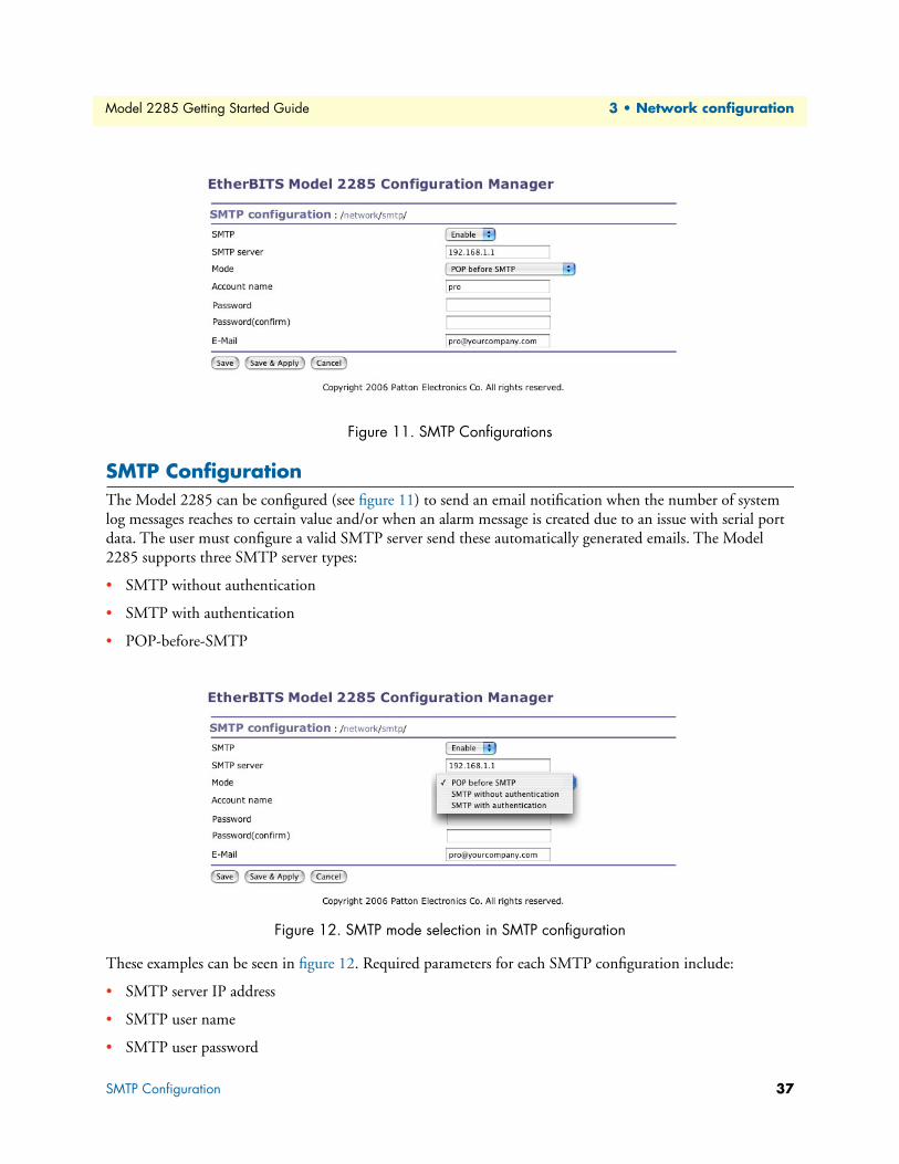
Model 2285 Getting Started Guide 3 • Network configuration
Figure 11. SMTP Configurations
SMTP ConfigurationThe Model 2285 can be configured (see figure 11) to send an email notification when the number of system
log messages reaches to certain value and/or when an alarm message is created due to an issue with serial port
data. The user must configure a valid SMTP server send these automatically generated emails. The Model
2285 supports three SMTP server types:
• SMTP without authentication
• SMTP with authentication
• POP-before-SMTP
Figure 12. SMTP mode selection in SMTP configuration
These examples can be seen in figure 12. Required parameters for each SMTP configuration include:
• SMTP server IP address
• SMTP user name
• SMTP user password
SMTP Configuration 37

Model 2285 Getting Started Guide 3 • Network configuration
• Device mail address
The device mail address specifies the sender’s email address for all log and alarm delivery emails. SMTP servers
often check only the sender’s host domain name of the email address for validity. Consequently, the email
address set for the device can use an arbitrary username with a registered hostname (i.e.
[email protected] or [email protected]).
The SMTP user name and SMTP user password are required when either SMTP with authentication or POP-
before-SMTP mode is selected.
Figure 13. IP filtering configuration
IP FilteringThe Model 2285 prevents unauthorized access using an IP address based filtering method (see figure 13). The
users can allow one of the following scenarios by changing the parameter settings:
• Any host cannot access a specific service of the Model 2285
• Only one host of a specific IP address can access a specific service of the Model 2285
• Hosts on a specific subnet can access a specific service of the Model 2285
• Any host can access a specific service of the Model 2285
The IP filtering feature is intended to control access to Telnet console, SSH console, Web server or each port,
which may be enabled or disabled. The factory default of the filtering feature is “All services and ports are
accessible from any host”.
The meanings of each parameter in IP filtering configuration are as follows:
Interface Apply IP filtering rule to the incoming packet of Model 2285. This is fixed parameter as eth0(Read-Only).
IP Filtering 38

Model 2285 Getting Started Guide 3 • Network configuration
Option and IP address/maskInput field to describe a specific range of host on the network. The user may allow a host or a group of hosts to
access the Model 2285. The user must then enter the IP address and subnet of access. Any user on a remote
host must stay in the specified subnet boundary to access the Model 2285. To allow only a specific host to
access the Model 2285, enter the IP address of the specific host and just give 255.255.255.255 for the subnet
with Normal option. To allow any hosts to have access to the Model 2285, give 0.0.0.0 for both of the IP
address and subnet with Normal option also. Refer to table 4 for more details.
Service Service to which will be applied to the IP filtering rule. User can select one of Telnet, SSH, HTTP, HTTPS or
each serial port
Chain ruleSet the basic rule for the host to access the Model 2285 as one of Accept or Drop.
Figure 14. IP filtering configuration for each service and serial port
The Model 2285 also provides users with simple configuration way to block a specific service(s) or serial ports
from all hosts. If the user should set any service option as “Drop all” (see table 14), then all access to the service
from the network will be blocked.
Table 4. Input examples of Option and IP address/mask combination
Allowable HostsInput format
OptionIP address/mask
Any host 0.0.0.0/0.0.0.0 Normal192.168.1.120 192.168.1.120/255.255.255.255 NormalAny host except 192.168.1.120 192.168.1.120/255.255.255.255 Invert192.168.1.1 ~ 192.168.1.254 192.168.1.0/255.255.255.0 Normal192.168.0.1 ~ 192.168.255.254 192.168.0.0/255.255.0.0 Normal192.168.1.1 ~ 192.168.1.126 192.168.1.0/255.255.255.128 Normal192.168.1.129 ~ 192.168.1.254 192.168.1.128/255.255.255.128 NormalNone 0.0.0.0/0.0.0.0 Invert
IP Filtering 39

Model 2285 Getting Started Guide 3 • Network configuration
SYSLOG server configurationThe Model 2285 supports the use of a remote message logging service, SYSLOG service for the system and
port data logging. To use the remote SYSLOG service, the user must specify the SYSLOG server’s IP address
and the facility to be used. Figure 15 shows the SYSLOG server configuration page which is located in the
web interface.
Figure 15. SYSLOG server configuration
To receive log messages from the Model 2285, the SYSLOG server must be configured as “remote reception
allowed”. If there is a firewall between the Model 2285 and the SYSLOG server, there must be a rule that
allows all outgoing and incoming UDP packets to travel across the firewall.
The Model 2285 supports SYSLOG facilities from local0 to local7. The user can employ these facilities to save
messages from the Model 2285 separately in the SYSLOG server.
If the SYSLOG service is enabled and the SYSLOG server configuration is properly set up, the user may con-
figure the storage location for the system log or port data log of the Model 2285 as SYSLOG server. For more
information about the configuration of port/system log storage location, refer to section“Port Logging” on
page 68 and section “System Logging” on page 72.
Locating serverOverviewIf users want the Model 2285 to work as a server (TCP or UDP), the host acting as a client has to know the IP
address of the Model 2285. However, under the dynamic IP address environment such as DHCP, arbitrary IP
address can be assigned to the Model 2285, which means special consideration is required to access the current
IP address of it. To tackle this problem, the Model 2285 can be configured to send its IP address information
whenever it is assigned a new IP address or periodically to a specific server called locating server. You can oper-
ate a specific host as your locating server or you can use your client host as a locating server simultaneously.
No special library or toolkit to implement locating server is provided. You have to implement your own appli-
cation by using the protocol provided below or contact us.
SYSLOG server configuration 40

Model 2285 Getting Started Guide 3 • Network configuration
Locating server configurationLocating server configuration screen is shown in figure 16. You have to configure locating server IP address,
locating server UDP port number and connection time interval as well as to use locating server feature or not.
Initially locating server feature is configured as “Disabled”.
Figure 16. Locating server configuration
Locating server communication protocolWhen the Model 2285 sends its IP address information to the locating server, data format will be as follows:
Data (n) format
Data ID
Description Magic Cookie Data(0) Data(1) … Data(n)
Bytes 4 Variable Variable VariableValue F1-AA-AA-BC
Description Data ID Length Data
Bytes 1 1 VariableValue 1~6 Variable Variable
ID Description Length
1 Device name var2 Model name var3 Serial number var4 MAC address 65 IP address 46 Local ports* 1 or 4 or 8
Locating server 41

Model 2285 Getting Started Guide 3 • Network configuration
Note Local ports: Each 2 byte data represent current local port setting of the corre-
sponding serial port. Local ports data length of Model 2285 should be 2
bytes. Configured local TCP (or UDP) port numbers for each serial port are
filled in the serial port number order base, (i.e. TCP or UDP port number
for serial port 1 first). If serial port is disabled, the local port number of that
serial port is regarded as 0.
Example of the Model 2285:
If port number = 7001 (1B59h), Local ports data = 1Bh, 59h
If serial port is disabled, Local port data = 00h, 00h
NFS server configurationThe Model 2285 supports NFS (Network File System) service for system or port data logging functions. To use
this service, the user must specify the IP address of a NFS server and the mounting path on the NFS server.
Figure 17 displays the NFS server configuration page located in the web configuration interface.
Figure 17. NFS server configuration
To store the Model 2285 log data to the NFS server, the NFS server must be configured as “read and write
allowed”. If there is a firewall between the Model 2285 and the NFS server, there must be a rule that allows all
outgoing and incoming packets to travel across the firewall.
If the NFS service is enabled and the NFS server configuration is properly set up, the user may configure the
storage location for the system log or port data log of the If there is a firewall between the Model 2285 and the
SYSLOG server, there must be a rule that allows all outgoing and incoming UDP packets to travel across the
Model 2285 as the NFS server. For more information about the configuration of port/system log storage loca-
tion, refer to section“Port Logging” on page 68 and section “System Logging” on page 72.
TCP service configurationIf a TCP session is established between two hosts, the connection should be closed (normally or abnormally)
by either of the hosts to prevent the lock-up of the corresponding TCP port. To prevent this type of lock-up
situation, the Model 2285 provides a TCP “keep-alive” feature. The Model 2285 will send packets back and
forth through the network periodically to confirm that the network exists . The corresponding TCP session is
closed automatically if there’s no response from the remote host.
NFS server configuration 42

Model 2285 Getting Started Guide 3 • Network configuration
To use the TCP “keep-alive” feature with the Model 2285, the users should configure three parameters
as follows:
• TCP keep-alive time: This represents the time interval between the last data transmission and keep-alive
packet submissions by the Model 2285. These “keep-alive” messages are sent to the remote host to confirm
that the session is still open. The default time value is 15 sec.
• TCP “keep-alive” probes: This represents how many “keep-alive” probes will be sent to the remote host,
until it decides that the connection is dead. Multiplied with the “TCP ’keep-alive’ intervals”, this gives the
time that a link is forced to close after a “keep-alive” packet has been sent for the first time. The default is
3 times
• TCP keep-alive intervals: This represents the waiting period until a “keep-alive” packet is retransmitted.
The default value is 5 seconds.
By default, the Model 2285 will send the keep-alive packets 3 times with 5 seconds interval after 15 seconds
have elapsed since the time when there’s no data transmitted back and forth.
Figure 18. TCP keep-alive configuration
TCP service configuration 43

Chapter 4 Serial port configuration
Chapter contentsOverview ...............................................................................................................................................................45
Serial Port Configuration.......................................................................................................................................47
Port Enable/Disable ........................................................................................................................................48
Port Title ........................................................................................................................................................48
Host Mode Configuration ..............................................................................................................................48
TCP mode ................................................................................................................................................49
UDP mode ................................................................................................................................................53
Modem emulation mode ...........................................................................................................................54
Remote host configuration ..............................................................................................................................58
Cryptography configuration ............................................................................................................................60
Secure Sockets Layer(SSL) cryptography method ......................................................................................60
RC4 cryptography method ........................................................................................................................63
Serial port parameters ......................................................................................................................................63
Modem configuration .....................................................................................................................................67
Port Logging ...................................................................................................................................................68
Port event handling configurations .................................................................................................................69
Event keywords .........................................................................................................................................70
44
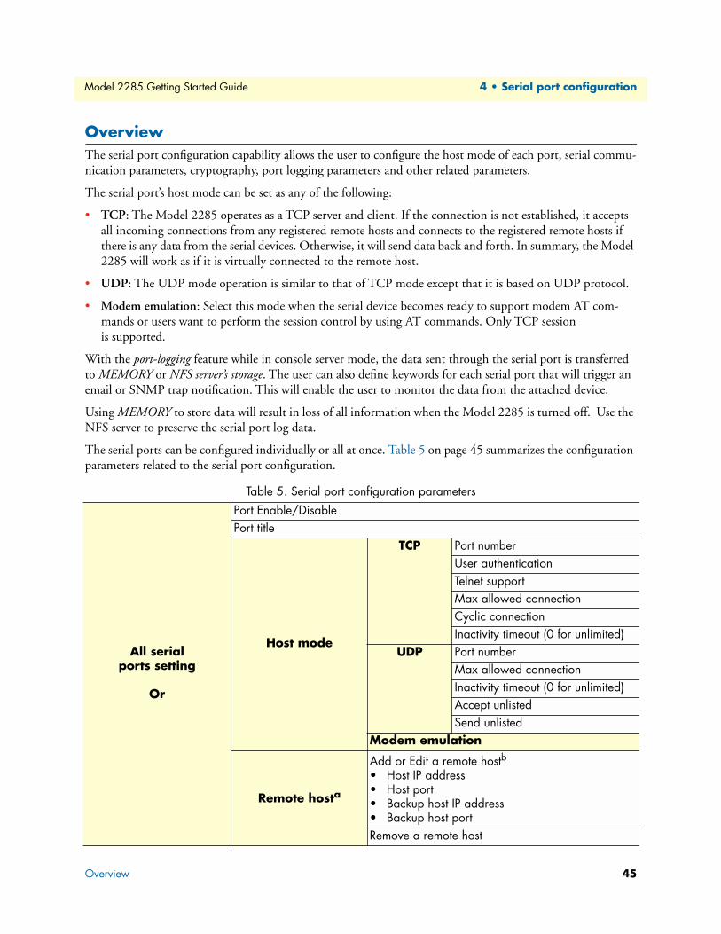
Model 2285 Getting Started Guide 4 • Serial port configuration
OverviewThe serial port configuration capability allows the user to configure the host mode of each port, serial commu-
nication parameters, cryptography, port logging parameters and other related parameters.
The serial port’s host mode can be set as any of the following:
• TCP: The Model 2285 operates as a TCP server and client. If the connection is not established, it accepts
all incoming connections from any registered remote hosts and connects to the registered remote hosts if
there is any data from the serial devices. Otherwise, it will send data back and forth. In summary, the Model
2285 will work as if it is virtually connected to the remote host.
• UDP: The UDP mode operation is similar to that of TCP mode except that it is based on UDP protocol.
• Modem emulation: Select this mode when the serial device becomes ready to support modem AT com-
mands or users want to perform the session control by using AT commands. Only TCP session
is supported.
With the port-logging feature while in console server mode, the data sent through the serial port is transferred
to MEMORY or NFS server’s storage. The user can also define keywords for each serial port that will trigger an
email or SNMP trap notification. This will enable the user to monitor the data from the attached device.
Using MEMORY to store data will result in loss of all information when the Model 2285 is turned off. Use the
NFS server to preserve the serial port log data.
The serial ports can be configured individually or all at once. Table 5 on page 45 summarizes the configuration
parameters related to the serial port configuration.
Table 5. Serial port configuration parameters
All serial ports setting
Or
Port Enable/DisablePort title
Host mode
TCP Port numberUser authenticationTelnet supportMax allowed connectionCyclic connectionInactivity timeout (0 for unlimited)
UDP Port numberMax allowed connectionInactivity timeout (0 for unlimited)Accept unlistedSend unlisted
Modem emulation
Remote hosta
Add or Edit a remote hostb• Host IP address• Host port• Backup host IP address• Backup host portRemove a remote host
Overview 45

Model 2285 Getting Started Guide 4 • Serial port configuration
Individual serial port setting#1~#8(1/4)
Cryptography c SSLv3
Modem
Baud rateData bitsParityStop bitsFlow controlInter-character timeout (ms)DTR behaviorDSR behaviorEnable/Disable modemModem init-stringDCD behaviorAutomatic release modem connection
Port logging
Enable/Disable Port loggingPort log storage location Port log buffer sizeDisplay port log
Port event handling
Enable/Disable port event handlingNotification interval
Email notification
Enable/Disable Email notificationSubject of Email
Recipient’s Email address
SNMP notification
Enable/Disable SNMP notificationSubject of SNMP trap
SNMP trap receiver’s IP addressSNMP trap community
SNMP trap versionAdd/Edit an event keyword• Event keyword• Email notification• SNMP trap notification• Port commandRemove a keyword
a. TCP/UDP mode only
b. A backup host and port are used when connection to main host is failed
c. Remove a remote host
Table 5. Serial port configuration parameters (Continued)
Overview 46

Model 2285 Getting Started Guide 4 • Serial port configuration
Figure 19. Serial port configuration main screen
Figure 19 shows the web-based serial port configuration screen. This serial port configuration main screen
summarizes port information. In this summary page, user can find which host mode, local port number and
serial port parameters are currently configured.
User can configure port parameters by clicking number or title of corresponding serial port (see figure 20).
Figure 20. Selecting port parameters
Serial Port ConfigurationIndividual Port Configurations of the Model 2285 are classified into eight groups:
• Port enable/disable
• Port title
• Host mode
• Cryptography
• Serial port parameters
• Modem configuration
• Port logging
• Port event handling
Serial Port Configuration 47
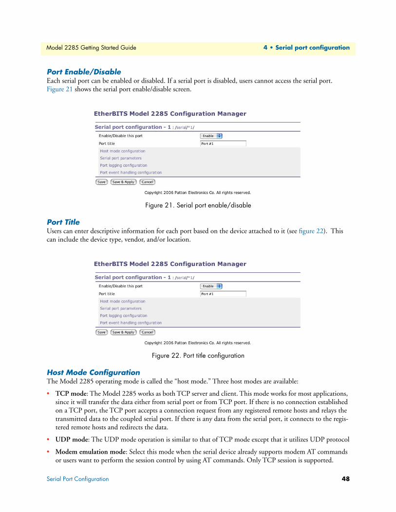
Model 2285 Getting Started Guide 4 • Serial port configuration
Port Enable/Disable Each serial port can be enabled or disabled. If a serial port is disabled, users cannot access the serial port.
Figure 21 shows the serial port enable/disable screen.
Figure 21. Serial port enable/disable
Port TitleUsers can enter descriptive information for each port based on the device attached to it (see figure 22). This
can include the device type, vendor, and/or location.
Figure 22. Port title configuration
Host Mode ConfigurationThe Model 2285 operating mode is called the “host mode.” Three host modes are available:
• TCP mode: The Model 2285 works as both TCP server and client. This mode works for most applications,
since it will transfer the data either from serial port or from TCP port. If there is no connection established
on a TCP port, the TCP port accepts a connection request from any registered remote hosts and relays the
transmitted data to the coupled serial port. If there is any data from the serial port, it connects to the regis-
tered remote hosts and redirects the data.
• UDP mode: The UDP mode operation is similar to that of TCP mode except that it utilizes UDP protocol
• Modem emulation mode: Select this mode when the serial device already supports modem AT commands
or users want to perform the session control by using AT commands. Only TCP session is supported.
Serial Port Configuration 48

Model 2285 Getting Started Guide 4 • Serial port configuration
Figure 23 shows the main workspace screen for the host mode configuration.
Figure 23. Host mode configuration (TCP mode)
TCP modeFor easier understanding of TCP modes, a simplified State Transition Diagram is often used. And to help users
understand the diagram, the TCP state of the Model 2285 is briefly described as follows.
• [Listen]—It represents “a waiting for a connection request from any registered remote host”. It is a default
start-up mode when it is set as TCP mode.
• [Closed]—It means “no connection state”. If the data transfer between a remote host and the Model 2285
is completed, the state is changed to this state as a result that either of the remote host or the Model 2285
sent a disconnection request. After this, the state is automatically changed to [Listen] mode.
• [Sync-Received]—The state is changed from [Listen] to [Sync-Received] if one of the remote hosts has sent
a connection request. If the Model 2285 accepts the request, the state is changed into [Established].
• [Sync-Sent]—If the Model 2285 has sent a connection request to a remote host, the state is changed from
[Closed] to [Sync-Sent]. This state is maintained until the remote host accepts the connection request.
• [Established]—It represents “an open connection”. If one of the hosts, the remote host or the Model 2285,
accepts a connection request from the other, the connection is opened and state is changed into [Estab-
lished].
• [Data]—When it is in [Established] state, data from a host will be transferred to the other one. For easier
understanding of the TCP session operation, we called the state as [Data] state when actual data transfer is
performed. Actually, the [Data] mode is a part of [Established] state as is described in the RFC 793 [Trans-
mission Control Protocol]. This is a normal state for the data transfer phase of the connection.
Serial Port Configuration 49

Model 2285 Getting Started Guide 4 • Serial port configuration
The Model 2285 works as either TCP server or client according to the situation. This will be the typical mode
for most applications, since it will transfer the data either from serial port or from TCP port. The default TCP
state is [Listen] which is the same as that of TCP server mode.
1) Typical State Transition
[Listen] --> [Sync-Received] --> [Established] --> [Data] --> [Closed] --> [Listen]
Or
[Listen] --> [Sync-Sent] --> [Established] --> [Data] --> [Closed] --> [Listen]
The initial state is [Listen]. If there are data coming from the serial port, it will connect to the remote host as a
TCP client and then transfer data through the TCP port. If there is incoming connection request from the
remote host, it will accept the connection as a TCP server, and then transfer data through the serial port. Thus,
users can assume that the Model 2285 is always connected to the specified remote host.
2) Operations
Serial data transfer
Whenever the serial device sends data through the serial port of the Model 2285, data will be accumulated
on the serial port buffer of the Model 2285. If the buffer is full or the time gap reaches the inter-character
timeout (see section “Serial port parameters” on page 63 for details on inter-character timeout), the Model
2285 connects to the registered remote host(s), if a TCP session has not been established yet. If the Model
2285 succeeds in connecting to the remote host, the data in the serial port buffer will be transferred to the
host. Otherwise, all the data stored in the buffer will be cleared.
Session disconnection
The connected session will be disconnected when the remote host sends disconnection request or when no
data transfer activity is found through the serial port for certain amount of time, which is “Inactivity time-
out” (See section “Serial port parameters” on page 63 for details on Inactivity timeout). All the data
remained in the serial port buffer will be cleared when it is disconnected.
Connection request from remote host
All the incoming TCP connection requests will be rejected in TCP client mode.
3) Parameters
TCP listening port
This is the TCP port number through which a remote host can connect a TCP session, and, send and
receive data. Incoming connection request(s) to the ports other than TCP Listening Port will be rejected.
The Model 2285 does restrict the port number from 1024 to 65535 and if it is set as 0 only outgoing con-
nection is permitted. (TCP server mode)
User authentication
If the User authentication option is enabled, the user can access the port after entering the correct user ID
and password. Refer to section “User administration” on page 79 for details of user management.
Telnet protocol
In TCP mode, Model 2285 supports Telnet Com Port Control Option (RFC2217 compliant) so that user
can control serial parameters like baud rate, data bits and flow control option using his local RFC2217-
Serial Port Configuration 50

Model 2285 Getting Started Guide 4 • Serial port configuration
compliant Telnet client program. (Refer to section “Serial port parameters” on page 63 for more detail
information about serial parameters)
Usually this option is used with the RFC2217-compliant COM port redirector so that user can control
parameters of serial ports of Model 2285 using his serial port application program.
For this purpose, Patton OEM version of Serial/IP from Tactical Software, LLC is bundled with Model
2285. Refer to documentations of Serial/IP for more detail information about using the COM port redi-
rector. (Refer to appendix G, “Using Model 2285 with Serial/IP” on page 116 for more
detail information)
Max. allowed connection
The Model 2285 supports up to 8 multiple connections from external host(s) to the serial port. If there are
remote host connections by the remote host list configuration already, possible number of connection will
be reduced (Max. allowed connection - remote host(s) connected already). For example, if user set Max.
allowed connection as 8 and if there are 3 connections from Model 2285 to remote hosts, which are con-
figured in the remote host list, then maximum number of connection from external hosts to a serial port
will be reduced to 5. For more detailed information on remote host list configuration, refer to section
“Remote host configuration” on page 58.
Cyclic Connection
If Cyclic Connection function is enabled, the Model 2285 will make an attempt to connect to the user-
defined remote host(s) at a given interval even if there’s no incoming serial data from the device connected
to that serial port. If there is data on the remote host(s) to be sent to serial device, it can be transferred to
the serial device via Model 2285 serial port after the connection is established. Eventually, users can moni-
tor the serial device periodically by making the remote host send the serial command to the Model 2285
whenever it is connected to the remote host. This option is useful when users need to gather the device
Serial Port Configuration 51

Model 2285 Getting Started Guide 4 • Serial port configuration
information periodically even if the serial device does not send its data periodically. Figure 24 shows the
State Transition Diagram of the session operations in TCP mode.
Figure 24. State Transition Diagram of TCP mode
Inactivity Timeout
When Inactivity Timeout function is enabled, connection between remote host(s) and Model 2285 will be
closed automatically if there is no data transmission during the value which is set in Inactivity
Timeout configuration.
Serial Port Configuration 52

Model 2285 Getting Started Guide 4 • Serial port configuration
UDP modeThe UDP mode operation is similar to that of TCP mode except that it is based on UDP protocol and only
one pre-defined remote host is able to communicate with the Model 2285. Users do not have to configure
cyclic connection, since UDP is a connectionless protocol.
Figure 25. Host mode configuration (UDP mode)
1) Operations
If a remote host sends a UDP datagram to the one of UDP Local port of the Model 2285, Model 2285 first
checks whether it is from one of the hosts configured on remote host configuration. If the remote host is one of
the hosts configured on remote host configuration, then Model 2285 transfers the data through the serial port.
Otherwise, the Model 2285 discards the incoming UDP datagram. But user can force Model 2285 accept all
incoming UDP datagram regardless remote host configuration by setting Accept UDP datagram from unlisted
remote host parameter as Yes. If there is any incoming data from the serial port, the Model 2285 transfers the
data to the remote host defined on remote host configuration. If the remote port is not opened, the Model 2285
will not transfer the data.
2) Parameters
UDP receiving port
The concept is the same as TCP listening port.
Max. allowed connection
The concept is the same as that of TCP communication.
Accept UDP datagram from unlisted remote host
If Accept unlisted (Accept UDP datagram from unlisted remote host) function is set as No, Model 2285 will
accept only incoming UDP datagram from the remote host(s) configured on remote host configuration. On
Serial Port Configuration 53

Model 2285 Getting Started Guide 4 • Serial port configuration
the contrary, if Accept unlisted function is set as Yes, Model 2285 will accept all incoming UDP datagram
regardless remote host configuration.
Send to recent unlisted remote host
If Send unlisted (Send to recent unlisted remote host) function is set as Yes, Model 2285 sends data to the
remote host, which has connected Model 2285 recently. Recent unlisted remote host is a remote host,
which has accessed a corresponding serial port of Model 2285 but is not configured on remote host configu-
ration. Surely, Model 2285 also send data to the hosts, which are configured on remote host configuration. If
Send unlisted function is set as No, Model 2285 sends data only to the host(s) which are configured on
remote host configuration. Model 2285 maintains a recent unlisted remote host during the
Inactivity Timeout.
Inactivity Timeout
In UDP mode, Inactivity Timeout is used in maintaining recent unlisted remote host. If there is no data
transmission between unlisted remote host and serial port of Model 2285 during Inactivity Timeout,
Model 2285 will not send data from a serial port to the recent unlisted remote host again. Namely, Inactiv-
ity Timeout in UDP mode is the time maintained recent unlisted remote host list by Model 2285.
Note If user set Inactivity Timeout as 0 in UDP mode, Model 2285 does not allow
any new connection from/to remote host if the number of current remote
host exceeds Max. allowed connection.
Modem emulation mode1) Operations
In modem emulation mode, the serial port process acts as if it is a modem attached to the serial device. It
accepts AT modem commands and answers to them, as modems would do. It also handles the modem signals
correctly. Modem emulation mode is useful in the following cases.
• There already exists a modem attached to the user’s serial device.
If user’s serial device already has a modem for phone-line connection, it can be just replaced by the Model
2285 for Ethernet connection. What users need to do is to use an IP address (or domain name) and port
number instead of phone number as a parameter of ATA/ATDT commands.
• It is required to send serial data to the multiple remote hosts.
If the serial device should send data to the multiple hosts, modem emulation mode is required. For exam-
ple, the first data from the serial device can be sent to the first data acquisition server and the second to the
second server. What user device has to do is to change the IP address (or domain name) and port number
parameters whenever the device sends ATD(T) XXX command.
Serial Port Configuration 54

Model 2285 Getting Started Guide 4 • Serial port configuration
By using the modem emulation mode of the Model 2285, users can have their serial device connected to the
Ethernet network easily, which is cheaper than using phone line modem. Table 6 is a summarized AT com-
mand table which is supported by the Model 2285. Figure 26 on page 57 shows the typical case of the serial
port command flow when ATDA command is used to connect to the Ethernet network.
Table 6. AT commands supported in the Model 2285
Command Internal Operation Responsea (Verbose Code)
+++ Return to command input mode None
ATD(T)[remote IP or domain name]:[remote port][CR][LF]orATD(T)[remote IP][remote port][CR][LF]
Set TCP mode as TCP client mode. And then, try to connect to the specified remote host.e.g. atdt192.168.1.9:1002e.g. atdt1921680010091002Connect to IP address, 192.168.1.9, port 1002(Port Number is permitted from 1 to 65534)e.g. atdtps.patton.com:1002Connect to domain address ps.patton.com, port 1002
If successful,CONNECT [CR][LF]If failure in connection,NO CARRIER [CR][LF]If other errors,ERROR [CR][LF]
AT or ATZ [CR][LF] Initialize TCP socket and serial port If successful, OK [CR][LF]
If failure,ERROR [CR][LF]
If successful, OK [CR][LF]
If failure,ERROR [CR][LF]
ATA/ [CR][LF] Repeat last command
ATA[Local port number][CR][LF]
Set TCP mode as TCP server mode. And then, set TCP state as [Listen].-. If the command parameter, Local port number is not specified, the TCP session parameter, Local Port is used instead.
ATEn [CR][LF] E, E0: Disable echoE1: Enable echo
ATOn [CR][LF] O, O0: Turn to data mode
ATQn [CR][LF] Q, Q0: Response display on (default)Q1: Response display off
ATVn [CR][LF] V, V0: Response = <numeric code> [CR][LF]V1 (default): Response = <verbose code> [CR][LF]
AT&Dn [CR][LF] D, D0: ignore DTR(PC) signalD2(default): disconnect TCP session
AT&Fn [CR][LF] F, F0, F1: Restore default modem settings
AT&Kn [CR][LF] K, K0: No flow controlK3: RTS/CTS flow control (default)K4: Xon/Xoff (if supported)
AT&Sn [CR][LF] S, S0: DSR(PC) always highS1: DSR(PC) shows TCP connection
Serial Port Configuration 55

Model 2285 Getting Started Guide 4 • Serial port configuration
ATHn [CR][LF] H, H0: Disconnect current TCP connectionAll the data will be clearedH1: Keep the current TCP connection
OK [CR][LF]
ATIn [CR][LF] I, I0: display “Patton Electronics Co.”I3: display model numberOthers: display “OK”
<=
AT\Tn [CR][LF] Set inactivity timer to n minutes\T, \T0: inactivity timer disabled (default)
OK [CR][LF]
ATBn, ATCn, ATLn, ATMn, ATNn, ATP, ATT, ATYn, AT%Cn, AT%En, AT&Bn, AT&Gn, AT&In, AT&Qn, AT&V, ATMn, AT\An, AT\Bn, AT\Nn, ATXn
none OK [CR][LF]
ATS?, ATSn=x Internal S-register can be set or read.Default values are shown on Table 4-4Changed values are not preserved if the power is off.
<=
AT&Cn, AT&Wn, AT&Zn=x Factory default response is ERROR. This can be changed to OK by user configuration. (Figure 4 8)
ERROR [CR][LF]orOK [CR][LF]
ATFn [CR][LF] None If n=1OK [CR][LF]If others,ERROR [CR][LF]
ATWn None If n=0OK [CR][LF]If others,ERROR [CR][LF]
a. If Echo mode is enabled, the command will be sent back first. And then, corresponding response will be sent. If
disabled, only response will be sent.
Table 7. AT commands Response Code
Verbose Code(After “ATV1” command executed)
Non-Verbose Code(Numeric Code)(After “ATV0” command executed) Description
OK 0 Command executedCONNECT 1 Modem connected
to lineRING 2 A ring signal has been
detected
Table 6. AT commands supported in the Model 2285 (Continued)
Command Internal Operation Responsea (Verbose Code)
Serial Port Configuration 56

Model 2285 Getting Started Guide 4 • Serial port configuration
Figure 26. Typical case of command/data flow of modem emulation mode
NO CARRIER 3 Modem lost carrier signal
ERROR 4 Invalid command
Table 8. Default value of S-Registers
Index Default Value Index Default Value Index Default Value
0 ~ 1 0 2 43 3 134 10 5 8 6 27 30 8 2 9 6
10 14 11 100 12 5013 ~ 24 0 24 5 25 126 ~ 37 0 38 20 39 ~ 99 0
Table 7. AT commands Response Code
Verbose Code(After “ATV1” command executed)
Non-Verbose Code(Numeric Code)(After “ATV0” command executed) Description
Serial Port Configuration 57

Model 2285 Getting Started Guide 4 • Serial port configuration
In modem emulation mode, user can also set specific phone number to host address/port mapping table. If
user set the phone number to host address/port mapping table as shown on figure 27, Model 2285 will try to
connect to port 7001 of 192.168.1.1 host by the ’atdt5737772’ command in modem emulation mode.
Figure 27. Host mode configuration (Modem emulation mode)
Respond to AT&Cn, AT&Wn and AT&Zn with
For the following three AT commands,
AT&Cn, AT&Wn, AT&Zn
User can select the response as one of OK or ERROR.
Command echo delay(ms)
AT commands that are entered by user can be echoed with a delay specified in this menu.
This is useful if user uses modem emulation mode in RS485 mode.
Default command echo
User can disable or enable echo of AT command that is entered by user in this menu.
(Same functionality to ATEn command)
Remote host configurationRemote host configuration is the list of hosts that will receive data from serial port of Model 2285 when there
is data transmission from the serial port of the Model 2285.
In TCP mode, user can also configure secondary remote host (Backup host) that will receive data from serial
port if Model 2285 fails to connect to primary remote host. If a connection to the primary remote host can be
Serial Port Configuration 58

Model 2285 Getting Started Guide 4 • Serial port configuration
made, Model 2285 dose not send data to secondary remote host until connection to primary remote host
failed. And the maximum possible number of primary remote host is limited up to 4 remote connections.
In UDP mode, user can only configure a primary remote host because there is no way for Model 2285 to check
status of primary remote host, so secondary remote host is meaningless.
The maximum number of remote host is limited up to 4 in the Model 2285. Figure 28 shows Remote host
configuration pages of the Web UI. (TCP mode)
User can also set any effective domain name as Host IP address in the Remote host configuration.
Figure 28. Remote host configuration
Serial Port Configuration 59

Model 2285 Getting Started Guide 4 • Serial port configuration
Cryptography configurationThe Model 2285 supports encrypted sessions for only the TCP mode including modem emulation mode (not
UDP mode).
Figure 29. Cryptography configuration
Secure Sockets Layer(SSL) cryptography methodBy setting the cryptography method as SSL, the Model 2285 can communicate with another device supporting
SSLv3 cryptography method during encrypted sessions.
SSL was developed by Netscape for use between clients and servers. SSL layers on top of any transport protocol
and can run under application protocols such as HTTP. SSL aims to be secure, fast, and adaptable to other
Web protocols. SSL provides data security for applications that communicate across networks. SSL is a trans-
port-layer security protocol layered between application protocols and TCP/IP.
To initiate SSL sessions, exchange of messages called the SSL handshake is required between two devices
(Server and Client). The SSL protocol uses a combination of public-key and symmetric key encryption. Sym-
metric key encryption is much faster than public-key encryption, but public-key encryption provides better
authentication techniques. The handshake allows the server to authenticate itself to the client using public-key
techniques, and then allows the client and the server to cooperate in the creation of symmetric keys used for
rapid encryption, decryption, and tamper detection during the session that follows. The details of handshake
process step involved can be summarized as follows:
1. The client sends the server the client’s SSL version number, cipher settings, randomly generated data, and
other information the server needs to communicate with the client using SSL.
Serial Port Configuration 60

Model 2285 Getting Started Guide 4 • Serial port configuration
2. The server sends the client the server’s SSL version number, cipher settings, randomly generated data, and
other information the client needs to communicate with the server over SSL. The server also sends its own
certificate and, if the client is requesting a server resource that requires client authentication, requests the
client’s certificate.
3. The client uses some of the information sent by the server to authenticate the server. If the server cannot be
authenticated, the user is warned of the problem and informed that an encrypted and authenticated con-
nection cannot be established. If the server can be successfully authenticated, the client goes on to
next step.
4. Using all data generated in the handshake so far, the client (with the cooperation of the server, depending
on the cipher being used) creates the premaster secret for the session, encrypts it with the server’s public-
key (obtained from the server’s certificate, sent in step 2), and sends the encrypted premaster secret to the
server. SSL differ in the way this "shared" master secret is created
5. If the server has requested client authentication (an optional step in the handshake), the client also signs
another piece of data that is unique to this handshake and known by both the client and server. In this case
the client sends both the signed data and the client’s own certificate to the server along with the encrypted
premaster secret.
6. If the server has requested client authentication, the server attempts to authenticate the client. If the client
cannot be authenticated, the session is terminated. if the client can be successfully authenticated, the server
uses its private key to decrypt the premaster secret, then performs a series of steps (which the client also
performs, starting from the same premaster secret) to generate the master secret.
7. Both the client and the server use the master secret to generate the session keys, which are symmetric keys
used to encrypt and decrypt information exchanged during the SSL/TLS session and to verify its integ-
rity—that is, to detect any changes in the data between the time it was sent and the time it is received over
the SSL connection.
8. The client sends a message to the server informing it that future messages from the client will be encrypted
with the session key. It then sends a separate (encrypted) message indicating that the client portion of the
handshake is finished.
9. The server sends a message to the client informing it that future messages from the server will be encrypted
h the session key. It then sends a separate (encrypted) message indicating that the server portion of the
handshake is finished.
10. The SSL handshake is now complete, and the SSL session has begun. The client and the server use the ses-
sion keys to encrypt and decrypt the data they send to each other and to validate its integrity.
Serial Port Configuration 61

Model 2285 Getting Started Guide 4 • Serial port configuration
Figure 30. Typical SSL Handshake Process
The Model 2285 can act as a SSL server or as a SSL client depending on status of TCP mode. If TCP connec-
tion with SSL is initiated from remote host first, Model 2285 acts as a SSL server during the SSL handshake
process. On the contrary, if TCP connection with SSL is initiated from serial port of Model 2285 first, Model
2285 acts as a SSL client during the SSL handshake process.
Serial Port Configuration 62

Model 2285 Getting Started Guide 4 • Serial port configuration
Figure 31. RC4 Cryptography configuration
RC4 cryptography method In RC4 cryptography mode, the Model 2285 encrypt and decrypt all TCP streams using a Key string. The
Model 2285 can communicate with another device or another Model 2285 that supports RC4 cryptography
mode with same Key string.
For the sample application programs of SSL/RC4 cryptography method, please contact the Patton Technical
support.
Serial port parametersTo connect the serial device to the Model 2285 serial port, the serial port parameters of the Model 2285 should
match exactly to that of the serial device attached. The serial port parameters are required to match this serial
communication. The parameters required for the serial communication are: UART type, baud rate, data bits,
parity, stop bits, flow control DTR/DSR behavior and inter-character timeout.
• UART type: First of all, the Model 2285 and the serial device must agree on the serial communication type,
which is one of RS232 mode, RS422(RS485 full) mode or RS485 half mode. User can set the serial com-
Serial Port Configuration 63

Model 2285 Getting Started Guide 4 • Serial port configuration
munication type by using DIP switch near by serial port in case of Model 2285. To change the serial com-
munication type, change the position of each DIP switch as shown on figure 32.
Figure 32. Serial communication type and DIP switch configuration
For more information about pin out of serial port and wiring diagram, refer to appendix C, “Cable Recom-
mendations” on page 99.
Note Turn off the power of the Model 2285 device before changing the position
of DIP switch in case of Model 2285. Changing the position of DIP switch
while the power is on may cause damage to the device.
(If the DIP switches are set incorrectly the Model 2285 will display
“Invalid” for the UART type on the UI as shown on Figure 33, which will
hinder communications to the serial port.)
\
Figure 33. Invalid UART type settings displayed on the Serial port configuration main screen
• Baud rate: The valid baud rate for the Model 2285 is as follows: 75, 150, 200, 300, 600, 1200, 2400, 4800,
9600, 14400, 19200, 38400, 57600, 115200, and 230400. The factory default setting is 9600.
• Data bits: Data bits can be between 7 bits and 8 bits. The factory default setting is 8 bits.
• Parity: Parity can be none, even or odd. The factory default setting is none.
• Stop bits: Stop bits can be between 1 bit and 2 bits. The factory default setting is 1 bit.
ON
RS-232 Mode
2 31
ON
RS-422/485 Full Mode
2 31
ON
RS-485 Half
2 31
Serial Port Configuration 64

Model 2285 Getting Started Guide 4 • Serial port configuration
Figure 34. Serial parameter configuration
• Flow control: The factory default setting of the flow control is None. Software Flow Control using XON/
XOFF and hardware flow control using RTS/CTS are supported by the Model 2285.
Software flow control method controls data communication flow by sending special characters XON/XOFF
(0x11/0x13) between two connected devices. And hardware flow control method controls data communi-
cation flow by sending signals back and forth between two connected devices.
Note Flow control is supported only in RS232 and RS422 mode. RS485 mode
does not support any kind of flow control method.
• DTR/DSR behavior: Purpose of the DTR/DSR pin is to emulate modem signal control or to control TCP
connection state by using serial port signal. The DTR is a write-only output signal, whereas the DSR is a
read-only input signal in the Model 2285.
The DTR option can be set to one of three types: always high, always low or high when TCP/UDP is opened.
If the DTR behavior is set to high when TCP/UDP is opened, the state of the DTR pin will be maintained
high if the TCP/UDP connection is established.
The DSR input behavior can be set to one of two types: none or allow TCP/UDP connection only by high. If
user sets the DSR input behavior as Allow TCP/UDP connection only by HIGH, TCP connection to remote
host from Model 2285 is made only when the DSR status is changed from low to high. And TCP connec-
tion to remote host is disconnected when the DSR status is changed from high to low. And also Model
2285 accepts TCP connection from the remote host only when the DSR status is high. In case of UDP
mode, Model 2285 receives UDP data from the remote host only when the DSR status is high. But In
modem emulation mode, the connection to the remote host will be disconnected when the DSR status is
changed from high to low regardless of the value of DSR behavior.
Serial Port Configuration 65

Model 2285 Getting Started Guide 4 • Serial port configuration
Serial device connected to Model 2285 can control TCP/UDP connection of Model 2285 by controlling
DTR signal of it.
Note DTR/DSR behavior configuration will not be effective when the modem is
enabled. DTR/DSR behavior does not effective in RS422 and RS485 mode.
• Inter-character timeout: This parameter defines the interval the Model 2285 fetches the overall serial data
from its internal buffer. If there is an incoming data through the serial port, the Model 2285 stores data into
the internal buffer. The Model 2285 transfers data stored in the buffer via TCP/IP, only if the internal
buffer is full or if the inter-character time interval reaches the time specified in the inter-character timeout
setting. If inter-character timeout is set at 0, then data stored in the internal buffer will be transferred imme-
diately without any delay.
Optimal inter-character timeout would be different according to your application but at least it must be
larger than one character interval within specified baud rate. For example, assume that the serial port is set
to 1200 bps, 8 Data bits, 1 stop bit, and no parity. In this case, the total number of bits to send a character
is 10 bits and the time required to transfer one character is
10 (bits) / 1200 (bits/s) * 1000 (ms/s) = 8.3 ms.
Therefore, you have to set inter-character timeout to be larger than 8.3 ms. The inter-character timeout is
specified in milliseconds.
Serial Port Configuration 66

Model 2285 Getting Started Guide 4 • Serial port configuration
Figure 35. Modem configuration
Modem configurationThe Model 2285 supports direct modem connection to the serial port. When user wants to connect to a
modem on its serial port, he must configure Modem init-string and DCD behavior on the modem configura-
tion page. The Model 2285 supports modem connection only when host mode is set as TCP mode.
• Enable/Disable modem: By enabling this menu, user can attach a modem directly to the serial port of
Model 2285. If this parameter is enabled, Model 2285 considers this port will be used for modem
use exclusively.
• Modem init-string: User can specify modem initialization string for his modem in Modem init-string
parameter. When a serial port is set to modem mode by setting Enable/Disable modem parameter as Enabled,
Model 2285 sends modem initialization string to the serial port whenever rising edge of DTR pin is
detected or parameter related with serial port configuration is changed.
• DCD behavior: If DCD behavior is set as Allow TCP connection only by HIGH, Model 2285 permits a con-
nection from the remote host only when the DCD status of serial port is high. This feature is useful when
user want to use a serial port only for dial-in modem mode. In this case, if there is no connection through
modem already, Model 2285 will not permit a TCP side connection.
• Automatic release modem connection: If Automatic release modem connection is set as Enable, modem con-
nection will be closed by Model 2285 if all TCP connections are closed. If this option is set as Disable,
modem connection will not be closed by Model 2285 even if all TCP connections are closed. Please note
that actual phone line connection will be closed if one of modems closes connection. That is, this option
Serial Port Configuration 67

Model 2285 Getting Started Guide 4 • Serial port configuration
can be used for Model 2285 to allow disconnection of a modem connection by itself when all TCP connec-
tions are closed.
If user wants to use dial-out function, he should set DCD behavior as None because he must be able to
access modem connected to a serial port to send dial out command to the modem first.
Port LoggingWith the port logging feature, the data sent through the serial port is stored to MEMORY or a mounting point
on an NFS server.
• Enable/disable port logging: This parameter defines whether to enable or disable the port-logging feature.
The factory default setting is [disabled].
• Port log storage location: The port log data can be stored to the Model 2285’ internal memory or the
mounting point on an NFS server. If the internal memory is used to store port log data, the port log data
will be cleared when the Model 2285 is turned off. To preserve the serial port log data, set the storage loca-
tion to be the NFS server. To do this, the user must configure the NFS server in advance. Refer to section
“NFS server configuration” on page 42 for details of NFS server configuration.
• Port log buffer size: This parameter defines the maximum amount of port log data to be logged. When
using internal memory to store the log data, the total size of the port buffer cannot exceed 10 kbytes.
When using an NFS server to store log data, the maximum port buffer size is unlimited. The user should
configure the NFS server to ensure that the port logging system works properly.
Figure 36. Port logging configuration
Serial Port Configuration 68

Model 2285 Getting Started Guide 4 • Serial port configuration
Figure 37. Port event-handling configurations
Port event handling configurationsThe Model 2285 provides users with a means for monitoring or reacting to data from serial device attached to
a serial port of it through Port event handling configuration. Namely, user can define keywords for each serial
port that will trigger the email/SNMP notification or command sent to the serial port directly on Port event
handling configuration. This will enable the user to monitor the data from the attached device or to manage/
control a device attached serial port directly when pre-defined keywords are detected. Also, the status of the
connection between the Model 2285 and the serial device and the status of the TCP connection between the
Model 2285 and remote hosts could be monitored and managed as well.
Each reaction can be configured individually upon each event. Reaction can be an email delivery, SNMP trap
sending, command sending or a combination of the reactions.
• Port event handling: If the user wants to enable port event handling feature, set Port event handling as
enable. This is a global parameter so if this feature is disabled, the Model 2285 does not take any actions on
port events.
• Notification interval: To prevent Model 2285 from being trapped in handling port event, there is a Notifi-
cation interval parameter. Model 2285 will send notification email or SNMP trap every Notification interval
even it detects predefined keyword within Notification interval. The smaller value of this parameter will
result in immediate response for predefined keyword and heavy usage of system resources. The largest value
accepted by user is recommended to prevent system resource usage minimization.
Serial Port Configuration 69

Model 2285 Getting Started Guide 4 • Serial port configuration
Note The port command in keyword response is not affected by this parameter.
Port command will be sent immediately when the corresponding keyword
is detected.
• Email notification: This parameter enables or disables Email notification feature of the Model 2285. When
Model 2285 sends Email notification, it uses the SMTP server configured in SMTP server configuration. If
the SMTP server is not configured correctly or disabled, Email feature will be disabled. For details of SMTP
server configurations and descriptions, refer to section “SMTP Configuration” on page 37.
• Subject of Email: This parameter set the subject of Email that will be sent by Model 2285 when pre-defined
keyword is detected.
• Recipient’s Email address: This parameter set mail recipient who will receive notification mail when pre-
defined keyword is detected.
• SNMP trap notification: This parameter enables or disables SNMP trap notification feature of
Model 2285.
• Subject of SNMP trap: This parameter set the subject of SNMP trap that will be sent by Model 2285 when
pre-defined keyword is detected.
• SNMP trap receiver’s IP address: This parameter sets the IP address of SNMP trap receiver that will receive
SNMP trap notification when pre-defined keyword is detected.
• SNMP trap community: This parameter sets a community that will be included in SNMP trap message
when pre-defined keyword is detected.
• SNMP trap version: This parameter sets a version of SNMP trap, which will be sent when pre-defined key-
word is detected.
Event keywordsThe user can assign event keywords so that the Model 2285 takes actions such as sending e-mail notification,
sending SNMP trap notification or sending pre-defined command to a serial port if the keyword is detected at
the serial port.
• Event keyword: User can specify any words, which he/she wants to set as a keyword.
• Email notification: User can select enable or disable for the Email notification action on keyword selected.
• SNMP trap notification: User can select enable or disable for the SNMP trap notification action on key-
word selected.
• Port command: Model 2285 supports direct reaction to a device attached to serial port when pre-defined
keyword is detected. User can specify command or string, which will be sent to a serial port on this menu.
Serial Port Configuration 70

Chapter 5 System administration
Chapter contentsIntroduction ..........................................................................................................................................................72
System Logging .....................................................................................................................................................72
Change Password...................................................................................................................................................73
Device Name Configuration..................................................................................................................................74
Date and Time Settings .........................................................................................................................................74
Factory Reset .........................................................................................................................................................75
Firmware Upgrade.................................................................................................................................................76
User administration ...............................................................................................................................................79
71

Model 2285 Getting Started Guide 5 • System administration
IntroductionThe Model 2285 displays the system status and the log data via a Status Display Screen. This screen is used for
management purposes. System status data includes the model name, serial number, firmware version and the
network configuration of the Model 2285. The Model 2285 can also be configured to deliver log data auto-
matically via email to a specified recipient with the system-logging feature.
The users can configure the Model 2285’ device name, date and time settings, and reload factory default set-
tings in this menu group. The users can also upgrade the firmware of the Model 2285 using the web interface,
remote consoles or serial console.
Figure 38. System status display
System LoggingThe Model 2285 provides both the system logging feature and the system log status display. The user may con-
figure the Model 2285 to enable or disable the system logging process, the system log buffer size, as well as
select the log storage location.
System log storage location: The system log can be stored in the Model 2285 internal memory, the mounting
point on an NFS server or the SYSLOG server. If the internal memory is used to store system log data, the log
data will be cleared when the Model 2285 is turned off. To preserve the system log data, set the storage location
to be SYSLOG server or NFS server. To do this, the user must configure the corresponding media in advance.
Unless the media is properly set up, the log will not be written to a specified storage location properly.
Introduction 72

Model 2285 Getting Started Guide 5 • System administration
Figure 39. System log configuration and view
The Model 2285 can also be configured to send log data automatically if the number of logs unsent reaches a
pre-defined number. If enabled, the user must set parameters to initiate the creation of a email. These parame-
ters would include the number of logs required to trigger an email, the recipient’s email address, etc. Figure 39
shows the configuration and system log view screen.
Change PasswordThe password for the administrative system user (root) of Model 2285 can be changed using this menu.
This password is required when user wants to access serial console, telnet/ssh console or Web UI of Model
2285. (Refer to the section “User administration” on page 79 for details about port user management)
Figure 40. Changing the password
Change Password 73

Model 2285 Getting Started Guide 5 • System administration
Device Name ConfigurationThe Model 2285 has its own name for administrative purposes. Figure 41 shows the device name configura-
tion screen. When user changes Device name, hostname of Model 2285 will be also changed.
Figure 41. Device name configuration
Note The user cannot set space character as a device name. If user sets blank as
Device name then hostname is set as IP address of Model
2285 automatically.
And also the device name is utilized for management program, Model 2285
Manager.
Date and Time SettingsThe Model 2285 maintains current date and time information.
Note The Model 2285 does not have a battery for internal clock. Current date and
time setting will not be retained after system rebooting. So it is recom-
mended to use NTP server to maintain correct date and time in the
Model 2285.
The user can change the current date and time, as shown in figure 42.
Figure 42. Date and time configuration
Device Name Configuration 74

Model 2285 Getting Started Guide 5 • System administration
The user can also use an NTP (Network Time Protocol) server for setting the time of the Model 2285 as
shown in figure 43. If the NTP feature is enabled, the Model 2285 will obtain the date and time information
from the NTP server at each reboot. If the NTP server is set to 0.0.0.0, the Model 2285 will use the default
NTP servers. In this case, the Model 2285 should be connected from the network to the Internet. The user
may also need to set the time offset from UTC depending on the users’ location.
Figure 43. NTP configuration
Factory ResetThe user may restore the factory default settings at any time using this menu. (User can also restore the factory
default settings using the reset switch near by serial console port.)
Figure 44. Factory Reset
Factory Reset 75

Model 2285 Getting Started Guide 5 • System administration
Firmware UpgradeFirmware upgrades are available via serial, remote console or web interface. The latest upgrades are available on
the Patton web site at http://www.patton.com/support/downloads/.
Figure 45 shows the firmware upgrade web interface.
To upgrade firmware via the web:
1. Select the latest firmware binary by clicking browse button.
2. Select and upload the selected version.
3. Once the upgrade has been completed, the system will reboot to apply the changes.
Figure 45. Firmware upgrade
To use either a remote or serial console to upgrade your firmware, the TELENT/SSH or terminal emulation
program must support Zmodem transfer protocol. The previous settings will be retained after the
firmware upgrade.
To upgrade firmware via a remote console:
1. Obtain the latest firmware.
2. Connect the terminal emulation program using either TELENT/SSH or a serial console port. (TELNET
or SSH is recommended since the process of firmware upgrade by serial console requires extremely
long time.)
Firmware Upgrade 76

Model 2285 Getting Started Guide 5 • System administration
3. Select from the firmware upgrade menu as below:
login: root
Password:
# editconf
_] / [________________________________________________________________________
1. Network configuration
2. Serial port configuration
3. System administration
________________________________________________________________________________
COMMAND (Display HELP: help)>3
_] System administration [____________________________________________________
1. System status
2. System logging
3. Device Name: Model 2285
4. Date and time
5. Change password
6. User Administration
7. Factory reset
8. Firmware upgrade
________________________________________________________________________________
COMMAND (Display HELP: help)>8
_] Firmware upgrade [_________________________________________________________
Do you want to upgrade firmware? [yes/no] yes
Transfer firmware by zmodem using your terminal application.
To escape, press Ctrl+X
**B0ff000005b157
Firmware Upgrade 77

Model 2285 Getting Started Guide 5 • System administration
4. Follow the online directions and transfer the firmware binary file using the Zmodem protocol as shown in
figure 46.
Figure 46. Transfer binary file by Zmodem (TeraTerm Pro)
5. Once the upgrade has been completed, the system will reboot to apply the changes
6. If the firmware upgrade fails, the Model 2285 will display error messages as shown below. It will also main-
tain the current firmware version.
_] Firmware upgrade [_________________________________________________________
Do you want to upgrade firmware? [yes/no] yes
Transfer firmware by zmodem using your terminal application.
To escape, press Ctrl+X
**B0ff000005b157
**B0ff000005b157
**B0ff000005b157
**B0ff000005b157
Firmware upgrade failed !
Now reboot ...
Firmware Upgrade 78

Model 2285 Getting Started Guide 5 • System administration
User administrationUser can enable port authentication, then user should enter correct user ID and password of each port when he
tries to access the serial port.
The user ID and password for each serial port can be set using this menu. When user adds a new user for serial
port, he can also assign permissible serial ports to the user selectively, as shown on figure 47.
Figure 47. Port user administration
Note System user (root) cannot access serial ports unless he is also added as a port
user in this menu.
Figure 48. Port user configuration
To set the password for the port user or to change the configuration of each port user, click the corresponding
number associated with the port user on port user administration page, then port user configuration page will
be displayed as shown on figure 48.
User administration 79

Chapter 6 System statistics
Chapter contentsIntroduction ..........................................................................................................................................................81
Network Interfaces Statistics..................................................................................................................................81
Serial Ports Statistics ..............................................................................................................................................81
IP Statistics .....................................................................................................................................................82
ICMP Statistics .....................................................................................................................................................84
TCP Statistics........................................................................................................................................................85
UDP Statistics .................................................................................................................................................86
80

Model 2285 Getting Started Guide 6 • System statistics
IntroductionThe Model 2285 Web interface provides system statistics menus. The user can use these menus to access statis-
tical data and tables stored in the Model 2285 memory. Network interfaces statistics and serial ports statistics
display statistical usage of the link layer, lo, eth and serial ports. IP, ICMP, TCP and UDP statistics display
usages of four primary components in the TCP/IP protocol suite.
Network Interfaces StatisticsNetwork interfaces statistics displays basic network interfaces usage of the Model 2285, lo and eth0. lo is a local
loop back interface and eth0 is a default network interface of Model 2285.
Figure 49. Network interfaces statistics
Serial Ports StatisticsSerial ports statistics displays the usage history of 32 serial ports, baud rate configurations and each port’s pin
status. ( : On : Off )
Figure 50. Serial ports status
Introduction 81

Model 2285 Getting Started Guide 6 • System statistics
IP StatisticsThe IP Statistics screen provides statistical information about packets/connections using an IP protocol. Defi-
nitions and descriptions of each parameter are described below:
Figure 51. IP statistics
• Forwarding: Specifies whether IP forwarding is enabled or disabled.
• DefaultTTL: Specifies the default initial time to live (TTL) for datagrams originating on a
particular computer.
• InReceives: Shows the number of datagrams received.
• InHdrErrors: Shows the number of datagrams received that have header errors. Datagrams Received
Header Errors is the number of input datagrams discarded due to errors in their IP headers, including bad
checksums, version number mismatch, other format errors, time-to-live exceeded, errors discovered in pro-
cessing their IP options, etc.
• InAddrErrors: Specifies the number of datagrams received that have address errors. These datagrams are dis-
carded because the IP address in their IP header’s destination field was not a valid address to be received at
this entity. This count includes invalid addresses (for example, 0.0.0.0) and addresses of unsupported
Classes (for example, Class E).
• ForwDatagrams: Specifies the number of datagrams forwarded.
• InUnknownProtos: Specifies the number of locally addressed datagrams received successfully but discarded
because of an unknown or unsupported protocol.
• InDiscard: Specifies the number of input IP datagrams for which no problems were encountered to prevent
their continued processing, but which were discarded (for example, for lack of buffer space). This counter
does not include any datagrams discarded while awaiting reassembly.
Serial Ports Statistics 82

Model 2285 Getting Started Guide 6 • System statistics
• InDelivers: Specifies the number of received datagrams delivered.
• OutRequests: Specifies the number of outgoing datagrams that an IP is requested to transmit. This number
does not include forwarded datagrams.
• OutDiscards: Specifies the number of transmitted datagrams discarded. These are datagrams for which no
problems were encountered to prevent their transmission to their destination, but which were discarded (for
example, for lack of buffer space.) This counter would include datagrams counted in Datagrams Forwarded
if any such packets met this (discretionary) discard criterion.
• OutNoRoutes: Specifies the number of datagrams for which no route could be found to transmit them to
the destination IP address. These datagrams were discarded. This counter includes any packets counted in
Datagrams Forwarded that meet this “no route” criterion.
• ReasmTimeout: Specifies the amount of time allowed for all pieces of a fragmented datagram to arrive. If all
pieces do not arrive within this time, the datagram is discarded.
• ReasmReqds: Specifies the number of datagrams that require reassembly.
• ReasmOKs: Specifies the number of datagrams that were successfully reassembled.
• ReasmFails: Specifies the number of datagrams that cannot be reassembled.
• FragOKs: Specifies the number of datagrams that were fragmented successfully.
• FragFails: Specifies the number of datagrams that need to be fragmented but couldn’t be because the IP
header specifies no fragmentation. For example, if the datagrams “Don’t Fragment” flag was set, the data-
gram would not be fragmented. These datagrams are discarded.
• FragCreates: Specifies the number of fragments created.
Serial Ports Statistics 83
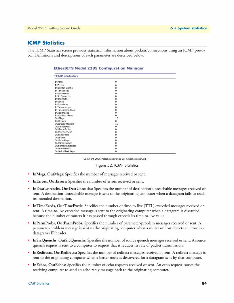
Model 2285 Getting Started Guide 6 • System statistics
ICMP StatisticsThe ICMP Statistics screen provides statistical information about packets/connections using an ICMP proto-
col. Definitions and descriptions of each parameter are described below:
Figure 52. ICMP Statistics
• InMsgs, OutMsgs: Specifies the number of messages received or sent.
• InErrors, OutErrors: Specifies the number of errors received or sent.
• InDestUnreachs, OutDestUnreachs: Specifies the number of destination-unreachable messages received or
sent. A destination-unreachable message is sent to the originating computer when a datagram fails to reach
its intended destination.
• InTimeExcds, OutTimeExcds: Specifies the number of time-to-live (TTL) exceeded messages received or
sent. A time-to-live exceeded message is sent to the originating computer when a datagram is discarded
because the number of routers it has passed through exceeds its time-to-live value.
• InParmProbs, OutParmProbs: Specifies the number of parameter-problem messages received or sent. A
parameter-problem message is sent to the originating computer when a router or host detects an error in a
datagram’s IP header.
• InSrcQuenchs, OutSrcQuenchs: Specifies the number of source quench messages received or sent. A source
quench request is sent to a computer to request that it reduces its rate of packet transmission.
• InRedirects, OutRedirects: Specifies the number of redirect messages received or sent. A redirect message is
sent to the originating computer when a better route is discovered for a datagram sent by that computer.
• InEchos, OutEchos: Specifies the number of echo requests received or sent. An echo request causes the
receiving computer to send an echo reply message back to the originating computer.
ICMP Statistics 84

Model 2285 Getting Started Guide 6 • System statistics
• NEchoReps, OutEchoReps: Specifies the number of echo replies received or sent. A computer sends an
echo reply in response to receiving an echo request message.
• InTimestamps, OutTimestamps: Specifies the number of time-stamp requests received or sent. A time-
stamp request causes the receiving computer to send a time-stamp reply back to the originating computer.
• InTimestampReps, OutTimestampReps: Specifies the number of time-stamp replies received or sent. A
computer sends a time-stamp reply in response to receiving a time-stamp request. Routers can use time-
stamp requests and replies to measure the transmission speed of datagrams on a network.
• InAddrMasks, OutAddrMasks: Specifies the number of address mask requests received or sent. A computer
sends an address mask request to determine the number of bits in the subnet mask for its local subnet.
• InAddrMaskReps, OutAddrMaskReps: Specifies the number of address mask responses received or sent. A
computer sends an address mask response in response to an address mask request.
TCP StatisticsThe TCP Statistics screen provides statistical information about packets/connections using a TCP protocol.
Definitions and descriptions of each parameter are described below:
Figure 53. TCP Statistics
• RtoAlgorithm: Specifies the retransmission time-out (RTO) algorithm in use. The Retransmission Algo-
rithm can have one of the following values.
- 0: CONSTANT - Constant Time-out
- 1: RSRE - MIL-STD-1778 Appendix B
- 2: VANJ - Van Jacobson’s Algorithm
- 3: OTHER - Other
• RtoMin: Specifies the minimum retransmission time-out value in milliseconds.
• RtoMax: Specifies the maximum retransmission time-out value in milliseconds.
• MaxConn: Specifies the maximum number of connections. If is the maximum number is set to -1, the
maximum number of connections are dynamic.
TCP Statistics 85

Model 2285 Getting Started Guide 6 • System statistics
• ActiveOpens: Specifies the number of active opens. In an active open, the client is initiating a connection
with the server.
• PassiveOpens: Specifies the number of passive opens. In a passive open, the server is listening for a connec-
tion request from a client.
• AttemptFails: Specifies the number of failed connection attempts.
• EstabResets: Specifies the number of established connections that have been reset.
• CurrEstab: Specifies the number of currently established connections.
• InSegs: Specifies the number of segments received.
• OutSegs: Specifies the number of segments transmitted. This number does not include
retransmitted segments.
• RetransSegs: Specifies the number of segments retransmitted.
• RetransSegs: Specifies the number of errors received.
• OutRsts: Specifies the number of segments transmitted with the reset flag set.
UDP StatisticsThe UDP Statistics screen provides statistical information about packets/connections using a UDP protocol.
Definitions and descriptions of each parameter are described below:
Figure 54. UDP Statistics
• InDatagrams: Specifies the number of datagrams received.
• NoPorts: Specifies the number of received datagrams that were discarded because the specified port
was invalid.
• InErrors: Specifies the number of erroneous datagrams that were received. Datagrams Received Errors is the
number of received UDP datagrams that could not be delivered for reasons other than the lack of an appli-
cation at the destination port.
• OutDatagrams: Specifies the number of datagrams transmitted.
TCP Statistics 86

Chapter 7 CLI guide
Chapter contentsIntroduction ..........................................................................................................................................................88
Flash partition .......................................................................................................................................................88
Supported Linux Utilities ......................................................................................................................................88
Shell & shell utilities .......................................................................................................................................88
File and disk utils ............................................................................................................................................88
System utilities ................................................................................................................................................88
Network utilities .............................................................................................................................................88
Accessing CLI........................................................................................................................................................88
87

Model 2285 Getting Started Guide 7 • CLI guide
IntroductionThe root user can access the Linux console command line interface (CLI) of the Model 2285 via the serial con-
sole or TELENT/SSH. In the CLI, the user can perform standard Linux commands to view the status of the
Model 2285, edit the configuration, apply configuration changes.
Flash partitionThe Model 2285 internal flash is partitioned as shown in the table below. The user can access files at /var
directory at his own risk. Simply accessing these files will not affect the Model 2285 after rebooting. However,
if the user invokes the command saveconf, the changes in the configuration file will be committed to the inter-
nal flash memory area of the Model 2285. This will result in the changes being kept after the reboot sequence.
Invalid configuration changes can affect the Model 2285 behavior. At worst, it may cause the Model 2285 to
become inoperable.
Supported Linux Utilities
Shell & shell utilitiescat, echo, more, pwd
File and disk utilsls, cp, mv, rm, mkdir, rmdir, touch, gunzip, gzip, tar, df, du, vi, e2fsck, mount, umount
System utilitiesdate, free, hostname, kill, killall, ps, reboot
Network utilitiesifconfig, iptables, route, ping
Accessing CLI Serial console:
1. Connect the console port of the Model 2285 with the PC serial port
2. Run a PC terminal emulation program
3. Configure the PC serial port to: 9600-8-N-1 No flow control
4. Press <enter>
Block Type Mount point Size (KB)
Mtdblock0 Bios None 128Mtdblock1 Kernel & ROM file system / 1024Mtdblock2 CRAMFS (Read only) /mtd 2880Mtdblock3 EXT2 (R/W) /cnf (normally unmounted) 64Total 4096
Introduction 88

Model 2285 Getting Started Guide 7 • CLI guide
5. Login with the Model 2285 root account
Telnet console:
1)telnet Pro_Series_ip_address
SSH console:
1)ssh -2 Pro_Series_ip_address
Note The Model 2285 only supports SSH v2 protocol.
Accessing CLI 89

Chapter 8 Contacting Patton for assistance
Chapter contentsIntroduction ..........................................................................................................................................................91
Contact information..............................................................................................................................................91
Patton support headquarters in the USA .........................................................................................................91
Alternate Patton support for Europe, Middle East, and Africa (EMEA) ..........................................................91
Warranty Service and Returned Merchandise Authorizations (RMAs)...................................................................91
Warranty coverage ..........................................................................................................................................91
Out-of-warranty service .............................................................................................................................92
Returns for credit ......................................................................................................................................92
Return for credit policy .............................................................................................................................92
RMA numbers ................................................................................................................................................92
Shipping instructions ................................................................................................................................92
90

Model 2285 Getting Started Guide 8 • Contacting Patton for assistance
IntroductionThis chapter contains the following information:
• “Contact information”—describes how to contact PATTON technical support for assistance.
• “Warranty Service and Returned Merchandise Authorizations (RMAs)”—contains information about the
RAS warranty and obtaining a return merchandise authorization (RMA).
Contact informationPatton Electronics offers a wide array of free technical services. If you have questions about any of our other
products we recommend you begin your search for answers by using our technical knowledge base. Here, we
have gathered together many of the more commonly asked questions and compiled them into a searchable
database to help you quickly solve your problems.
Patton support headquarters in the USA• Online support—available at http://www.patton.com
• E-mail support—e-mail sent to [email protected] will be answered within 1 business day
• Telephone support—standard telephone support is available 5 days a week, from 8:00am to 5:00pm EST
(1300 to 2200 UTC/GMT)—by calling +1 (301) 975-1007
• Fax—+1 (253) 663-5693
Alternate Patton support for Europe, Middle East, and Africa (EMEA)• Online support—available at http://www.patton-inalp.com
• E-mail support—email sent to [email protected] will be answered within 1 day
• Telephone support—standard telephone support is available five days a week—from 8:00 am to 5:00 pm
CET (0900 to 1800 UTC/GMT)—by calling +41 (0)31 985 25 55
• Fax—+41 (0)31 985 25 26
Warranty Service and Returned Merchandise Authorizations (RMAs)Patton Electronics is an ISO-9001 certified manufacturer and our products are carefully tested before ship-
ment. All of our products are backed by a comprehensive warranty program.
Note If you purchased your equipment from a Patton Electronics reseller, ask your
reseller how you should proceed with warranty service. It is often more con-
venient for you to work with your local reseller to obtain a replacement. Pat-
ton services our products no matter how you acquired them.
Warranty coverageOur products are under warranty to be free from defects, and we will, at our option, repair or replace the prod-
uct should it fail within one year from the first date of shipment. Our warranty is limited to defects in work-
manship or materials, and does not cover customer damage, lightning or power surge damage, abuse, or
unauthorized modification.
Introduction 91

Model 2285 Getting Started Guide 8 • Contacting Patton for assistance
Out-of-warranty servicePatton services what we sell, no matter how you acquired it, including malfunctioning products that are no
longer under warranty. Our products have a flat fee for repairs. Units damaged by lightning or other catastro-
phes may require replacement.
Returns for creditCustomer satisfaction is important to us, therefore any product may be returned with authorization within 30
days from the shipment date for a full credit of the purchase price. If you have ordered the wrong equipment or
you are dissatisfied in any way, please contact us to request an RMA number to accept your return. Patton is
not responsible for equipment returned without a Return Authorization.
Return for credit policy • Less than 30 days: No Charge. Your credit will be issued upon receipt and inspection of the equipment.
• 30 to 60 days: We will add a 20% restocking charge (crediting your account with 80% of the purchase
price).
• Over 60 days: Products will be accepted for repairs only.
RMA numbersRMA numbers are required for all product returns. You can obtain an RMA by doing one of the following:
• Completing a request on the RMA Request page in the Support section at www.patton.com
• By calling +1 (301) 975-1000 and speaking to a Technical Support Engineer
• By sending an e-mail to [email protected]
All returned units must have the RMA number clearly visible on the outside of the shipping container. Please
use the original packing material that the device came in or pack the unit securely to avoid damage during
shipping.
Shipping instructionsThe RMA number should be clearly visible on the address label. Our shipping address is as follows:
Patton Electronics Company
RMA#: xxxx
7622 Rickenbacker Dr.
Gaithersburg, MD 20879-4773 USA
Patton will ship the equipment back to you in the same manner you ship it to us. Patton will pay the return
shipping costs.
Warranty Service and Returned Merchandise Authorizations (RMAs) 92

Appendix A Compliance information
Chapter contentsEMC Compliance .................................................................................................................................................94
Radio and TV Interference (FCC Part 15) ............................................................................................................94
CE Declaration of Conformity ..............................................................................................................................94
Authorized European Representative .....................................................................................................................94
93

Model 2285 Getting Started Guide A • Compliance information
EMC Compliance • FCC Part 15, Class A
• EN55022, Class A
• EN55024
Radio and TV Interference (FCC Part 15)This equipment generates and uses radio frequency energy, and if not installed and used properly-that is, in
strict accordance with the manufacturer's instructions-may cause interference to radio and television reception.
This equipment has been tested and found to comply with the limits for a Class A computing device in accor-
dance with the specifications in Subpart B of Part 15 of FCC rules, which are designed to provide reasonable
protection from such interference in a commercial installation. However, there is no guarantee that interfer-
ence will not occur in a particular installation. If the equipment causes interference to radio or television recep-
tion, which can be determined by disconnecting the cables, try to correct the interference by one or more of
the following measures: moving the computing equipment away from the receiver, re-orienting the receiving
antenna, and/or plugging the receiving equipment into a different AC outlet (such that the computing equip-
ment and receiver are on different branches).
CE Declaration of ConformityWe certify that the apparatus identified in this document conforms to the requirements of Council Directive
89/336/EEC, as amended by Directives 92/31/EEC, 93/68/EEC, and 2004/108/EC on the approximation of
the laws of the member states relating to electromagnetic compatibility.
The safety advice in the documentation accompanying this product shall be obeyed. The conformity to the
above directive is indicated by the CE sign on the device.
Authorized European RepresentativeD R M Green
European Compliance Services Limited.
Oakdene House, Oak Road
Watchfield,
Swindon, Wilts SN6 8TD, UK
EMC Compliance 94

Appendix B Specifications
Chapter contentsSerial interface .......................................................................................................................................................96
Network interface..................................................................................................................................................96
Protocols ...............................................................................................................................................................96
Security .................................................................................................................................................................96
Modem emulation.................................................................................................................................................96
Management .........................................................................................................................................................96
Security .................................................................................................................................................................97
Diagnostic LEDs ...................................................................................................................................................97
Environmental.......................................................................................................................................................97
Physical .................................................................................................................................................................97
Power ....................................................................................................................................................................97
95

Model 2285 Getting Started Guide B • Specifications
Serial interface• 1-port
• Serial speeds: 75 bps to 230 kbps
• Flow Control: Hardware RTS/CTS, Software Xon/Xoff
• RJ45 connector
• Signals:
- RS232: Rx, Tx, RTS, CTS, DTR, DSR, DCD, GND
- RS422: Rx+, Rx-, Tx+, Tx-
- RS485: Data+, Data-
• Modem controls: DTR, DSR and DCD
Network interface • 10/100 Base-Tx Ethernet with RJ45 Ethernet connector
• Supports static and dynamic IP addresses
Protocols• ARP, IP/ICMP, TCP, UDP, Telnet, SSH v2
• SSLv3
• DNS, Dynamic DNS, HTTP, HTTPS, NFS
• SMTP with/without Authentication, pop-before SMTP
• DHCP client, NTP, SNMP v1 & v2
Security• User ID & Password
• HTTPS
• Secure terminal interface: SSH
• Data Encryption: SSLv3
• IP address filtering
Modem emulationFull support for AT commands
Management• Web, Telnet, SSH, Serial console port or Model 2285 Manager
• O/S support: Windows 98/ME/NT/2000/XP
Serial interface 96

Model 2285 Getting Started Guide B • Specifications
• System log: Automatic email delivery of error log
• System statistics: Full-featured system status display
• Firmware: Stored in Flash memory and upgradeable via telnet or web
Security• Packet filtering firewall for controlled access to and from LAN/WAN. Support for 255 rules in 32 filter sets.
16 individual connection profiles.
• DoS Detection/protection. Intrusion detection, Logging of session, blocking and intrusion events and Real-
Time alerts. Logging or SMTP on event.
• Password protected system management with a username/password for console and virtual terminal. Sepa-
rate user selectable passwords for SNMP RO/RW strings.
• Access list determining up to 5 hosts/networks which are allowed to access management system SNMP/
HTTP/TELNET.
• Logging or SMTP on events: POST, POST errors, PPP/DHCP, IP.
Diagnostic LEDs• PWR (power) red LED
• Link (10/100 Base Link) green LED
• Rx (Serial receive for each port) amber LED
• Tx (Serial transmit for each port) amber LED
Environmental• Operating temperature: 0 to 50°C
• Storage temperature: -20 to 66°C
• Humidity: 90% (Non-condensing)
Physical• Dimensions: 1.02H x 3.22W x 4.48D in. (26H x 82W x 114D cm)
• Weight: 10.6 ounces (0.3 kg)
Power• TBD
Connect the equipment to a 36–60 VDC source that is electri-cally isolated from the AC source. The 36–60 VDC source is to be reliably connected to earth.
CAUTIO
Security 97

Model 2285 Getting Started Guide B • Specifications
Power 98

Appendix C Cable Recommendations
Chapter contentsEthernet Pin-outs ................................................................................................................................................100
Console and Serial port pin-outs..........................................................................................................................101
Ethernet wiring diagram......................................................................................................................................102
Serial wiring diagram...........................................................................................................................................102
RS-232 serial wiring diagram ........................................................................................................................102
RS-422/485 serial wiring diagram .................................................................................................................103
99

Model 2285 Getting Started Guide C • Cable Recommendations
Ethernet Pin-outsThe Model 2285 uses a standard Ethernet connector, which is a shielded connector that is compliant with the
AT&T258 specifications. Table 9 shows the pin assignment and wire color.
Figure 55. Pin layout of the RJ45 connector
The interconnecting cables shall be acceptable for external use and shall be rated for the proper application with respect to volt-age, current, anticipated temperature, flammability, and mechanical serviceability.
Table 9. Pin assignment of the RJ45 connector for Ethernet
Pin Description Color
1 Tx+ White with orange2 Tx- Orange3 Rx+ White with green4 NC Blue5 NC White with blue6 Rx- Green7 NC White with brown8 NC Brown
CAUTIO
12345678
Ethernet Pin-outs 100

Model 2285 Getting Started Guide C • Cable Recommendations
Console and Serial port pin-outsThe pin assignment of the Model 2285 DB9 connector is summarized in table 10. Each pin has a function
according to the serial communication type configuration.
Figure 56. Pin layout of the DB-9 connector
The serial communication type can be set by DIP switch near by serial port. To change the serial communica-
tion type, change the position of each DIP switch as shown below. But please note that the power of the Model
2285 should be turned off before changing the serial communication type.
Figure 57. Serial communication type and DIP switch configuration
The interconnecting cables shall be acceptable for external use and shall be rated for the proper application with respect to volt-age, current, anticipated temperature, flammability, and mechanical serviceability.
Table 10. Pin assignment of DB-9 connector for console and serial port
Pin RS232 (console and serial ports) RS422 (serial ports only) RS485 (serial ports only)
1 DCD Tx+ Tx+2 Rx RX+ RX+3 Tx RTS+ -4 DTR CTS+ -5 GND GND GND 6 DSR TX- TX-7 RTS RTS- -8 CTS RX- RX-9 - CTS- -
CAUTIO
1 2 3 4 5
6 7 8 9
ON
RS-232 Mode
2 31
ON
RS-422/485 Full Mode
2 31
ON
RS-485 Half
2 31
Console and Serial port pin-outs 101

Model 2285 Getting Started Guide C • Cable Recommendations
Ethernet wiring diagram
Figure 58. Ethernet direct connection using crossover Ethernet cable
Figure 59. Ethernet connection using straight through Ethernet cable
Serial wiring diagram
RS-232 serial wiring diagram
Figure 60. RS-232 wiring diagram
Rx+(3)
Rx-(6)
Tx+(1)
Tx-(2)
Rx+(3)
Rx-(6)
Tx+(1)
Tx-(2)
Model 2285 Remote host
Rx+(3)
Rx-(6)
Tx+(1)
Tx-(2)
Rx+(3)
Rx-(6)
Tx+(1)
Tx-(2)
Model 2285 Hub
Rx+(3)
Rx-(6)
Tx+(1)
Tx-(2)
Remote host
Rx+(3)
Rx-(6)
Tx+(1)
Tx-(2)
Tx(3)
Rx(2)
RTS(7)
CTS(8)
DTR(4)
DSR(6)
Gnd(5)
Model 2285
Rx
Tx
CTS
RTS
DSR
DTR
Gnd
Serial device
RS-232
Ethernet wiring diagram 102

Model 2285 Getting Started Guide C • Cable Recommendations
RS-422/485 serial wiring diagram
Figure 61. RS-485 wiring diagram
*Data+ means that coupling of Tx+(1) pin and Rx+(2) pin
**Data- means that coupling of Tx-(6) pin and Rx-(8) pin
Figure 62. RS-422 wiring diagram
* Termination resistor at Tx side can be omitted if the signal status is good.
120 ohmModel 2285
**Data-
*Data+
Device1
Data- Data+
DeviceN - 1
Data- Data+
120 ohmDeviceN
**Data-
*Data+
N = max 31
RS-485 (Half)
120 ohmModel 2285
Tx-(6)
Tx+(1)
Device1
120 ohmDeviceN
Rx-
Rx+
N = max 31
RS-422/485 (Full)
120 ohm
Rx-(8)
Rx+(2)
120 ohm
Tx-
Tx+
DeviceN - 1
Rx-Rx+ Tx-Tx+ Rx-Rx+ Tx-Tx+
Serial wiring diagram 103

Appendix D Configuration files
Chapter contentsport1.conf............................................................................................................................................................105
filter.conf.............................................................................................................................................................105
snmp.conf............................................................................................................................................................106
104

Model 2285 Getting Started Guide D • Configuration files
port1.conf /serial/*1/parameter/baudrate=9600
/serial/*1/parameter/databit=0
/serial/*1/parameter/stopbit=0
/serial/*1/parameter/parity=0
/serial/*1/parameter/flowcontrol=0
/serial/*1/parameter/interchar_to=0
/serial/*1/parameter/dtr_option=0
/serial/*1/parameter/dsr_option=0
/serial/*1/modem/modem_init_string=q1e0s0=2
/serial/*1/modem/modem_dcd_option=0
/serial/*1/modem/modem_auto_disconnection_enable=0
/serial/*1/modem/modem_enable=0
/serial/*1/event/event_email_enable=0
/serial/*1/event/event_snmp_enable=0
/serial/*1/event/event_notification_interval=30
/serial/*1/event/event_enable=0
/serial/*1/hostmode/accept_unlisted=1
/serial/*1/hostmode/send_unlisted=1
/serial/*1/enable=1
/serial/*1/title=Port #1
/serial/*1/hostmode/mode=0
/serial/*1/hostmode/port=7001
/serial/*1/hostmode/userauth=0
/serial/*1/hostmode/telnet=0
/serial/*1/hostmode/max_connection=8
/serial/*1/hostmode/cyclic_time=0
/serial/*1/hostmode/inactive_time=0
filter.conf /network/filter/specification/telnet=1
/network/filter/specification/ssh=1
/network/filter/specification/http=1
/network/filter/specification/https=1
/network/filter/specification/port1=1
/network/filter/specification/port2=1
/network/filter/specification/port3=1
/network/filter/specification/port4=1
port1.conf 105

Model 2285 Getting Started Guide D • Configuration files
snmp.conf /network/snmp/syscontact=administrator
/network/snmp/sysname=ProSeries
/network/snmp/syslocation=my location
/network/snmp/sysservice=7
/network/snmp/powerontrapenable=0
/network/snmp/authtrapenable=1
/network/snmp/linkuptrapenable=0
/network/snmp/logintrapenable=0
/network/snmp/nms/*1=0.0.0.0 public 0
/network/snmp/nms/*2=0.0.0.0 public 0
/network/snmp/nms/*3=0.0.0.0 public 0
/network/snmp/nms/*4=0.0.0.0 public 0
/network/snmp/trap/*1=0.0.0.0 public 0
/network/snmp/trap/*2=0.0.0.0 public 0
/network/snmp/trap/*3=0.0.0.0 public 0
/network/snmp/trap/*4=0.0.0.0 public 0
snmp.conf 106

Appendix E Well-known port numbers
Chapter contentsIntroduction ........................................................................................................................................................108
107

Model 2285 Getting Started Guide E • Well-known port numbers
IntroductionPort numbers are divided into three ranges: Well Known Ports, Registered Ports, and Dynamic and/or Private
Ports. Well Known Ports are those from 0 through 1023. Registered Ports are those from 1024 through 49151.
Dynamic and/or Private Ports are those from 49152 through 65535.
Well Known Ports are assigned by IANA, and on most systems, can only be used by system processes or by pro-
grams executed by privileged users. Table A-3 shows some of the well-known port numbers. For more details,
please visit the IANA website: http://www.iana.org/assignments/port-numbers
Table 11. Well-known port numbers
Port number Protocol TCP/UDP
21 FTP (File Transfer Protocol) TCP22 SSH (Secure Shell) TCP23 Telnet TCP25 SMTP (Simple Mail Transfer Protocol) TCP37 Time TCP, UDP39 RLP (Resource Location Protocol) UDP49 TACACS, TACACS+ UDP53 DNS UDP67 BOOTP server UDP68 BOOTP client UDP69 TFTP UDP70 Gopher TCP79 Finger TCP80 HTTP TCP110 POP3 TCP119 NNTP (Network News Transfer Protocol) TCP
161/162 SNMP UDP443 HTTPS TCP
Introduction 108

Appendix F Guide to the Bios menu program
Chapter contentsOverview .............................................................................................................................................................110
Main menu..........................................................................................................................................................110
RTC configuration menu ....................................................................................................................................110
Hardware test menu ............................................................................................................................................111
A 4.5. Firmware upgrade menu ...........................................................................................................................114
109

Model 2285 Getting Started Guide F • Guide to the Bios menu program
OverviewThe bios menu provides a way to recover the Model 2285 unit, by using TFTP, as a disaster recovery option
and to diagnose the system hardware. If the user presses the <ESC> key within 3 seconds after the Model 2285
unit is powered up, the user will enter the bios menu program. From this menu program, the user can set vari-
ous system parameters, test system hardware, and perform firmware upgrades.
Note For Model 2285, the bios menu will be displayed only when the Console/
Data switch is located at the Console side.
Main menuAfter entering the bios menu program, the user will see following main menu page:
----------------------------------------------------------------------------- BIOS v1.0.0 (c) 1998-2005 Patton Electronics Co.
----------------------------------------------------------------------------- ----------------------------------------------------------------------------- Welcome to Boot Loader Configuration page
----------------------------------------------------------------------------- Select menu
1. RTC Configuration
2. Hardware test
3. Firmware upgrade [S/W Version : v1.0.0]
4. Exit and boot from flash
5. Exit and reboot
<ESC> Back, <ENTER> Refresh
----->
RTC configuration menuUsing the RTC configuration menu, the user can set the system time of the Model 2285. (There is no RTC
configuration menu in case of Model 2285)
----------------------------------------------------------------------------- RTC Configuration
----------------------------------------------------------------------------- Select Menu
1. Data(mm/dd/yy) : 05/19/05
2. Time(hh:mm:ss) : 15:02:28
<ESC> Back, <ENTER> Refresh
----->1
Enter Current Data(mm/dd/yy) : 05/20/05
Press the ENTER key to continue!!
----------------------------------------------------------------------------- RTC Configuration
----------------------------------------------------------------------------- Select Menu
1. Data(mm/dd/yy) : 05/20/05
2. Time(hh:mm:ss) : 15:02:41
<ESC> Back, <ENTER> Refresh
----->2
Enter Current Data(hh:mm:ss) : 15:03:40
Press the ENTER key to continue!!
Overview 110

Model 2285 Getting Started Guide F • Guide to the Bios menu program
----------------------------------------------------------------------------- RTC Configuration
----------------------------------------------------------------------------- Select Menu
1. Data(mm/dd/yy) : 05/20/05
2. Time(hh:mm:ss) : 15:03:41
<ESC> Back, <ENTER> Refresh
----->
Note There is no RTC configuration menu in case Model 2285.
Hardware test menuUsing the Hardware test menu, the user can test hardware components. There are three hardware test modes:
• One time
• Looping (without External test in Auto test)
• Looping (with External test in Auto test)
If the user selects One time, an auto test or each component test is performed just once. In this mode, the ping
test to the remote host (server IP address) and UART test are also performed once.
If the user selects Looping (without External test in Auto test), the auto test is performed repeatedly until the
user presses the <ctrl-c> keys. In this mode, the ping test to the remote host (server IP address) and UART test
are not performed.
If the user selects Looping (with External test in Auto test)', auto test is performed repeatedly until the user
presses the <ctrl-c> keys. And, the ping test to the remote host (server IP address) and UART test are also per-
formed repeatedly.
Note To perform the test on the Ethernet and UART properly, the user must con-
nect an Ethernet cable to the Ethernet port of the Model 2285 and must
plug the loopback connector to all the serial ports of the Model 2285. There
must exist a remote host with a valid IP address. The default server IP
address is 192.168.0.128 and it can be changed using the [Firmware
Upgrade] menu. Otherwise, the test may not be performed properly.
----------------------------------------------------------------------------- Hardware Test
----------------------------------------------------------------------------- Select menu
0. Test Mode - One Time
1. Auto test
2. DRAM test
3. FLASH test
4. EEPROM test
5. Ethernet test
6. UART Mode test
<ESC> Back, <ENTER> Refresh
-----> 0
Hardware test menu 111

Model 2285 Getting Started Guide F • Guide to the Bios menu program
----------------------------------------------------------------------------- Hardware Test
----------------------------------------------------------------------------- Select menu
0. Test Mode - Looping(Without External test in Auto Test)
1. Auto test
2. DRAM test
3. FLASH test
4. EEPROM test
5. Ethernet test
6. UART Mode test
<ESC> Back, <ENTER> Refresh
-----> 0
----------------------------------------------------------------------------- Hardware Test
----------------------------------------------------------------------------- Select menu
0. Test Mode - Looping(With External test in Auto Test)
1. Auto test
2. DRAM test
3. FLASH test
4. EEPROM test
5. Ethernet test
6. UART Mode test
<ESC> Back, <ENTER> Refresh
-----> 0
----------------------------------------------------------------------------- Hardware Test
----------------------------------------------------------------------------- Select menu
0. Test Mode - One Time
1. Auto test
2. DRAM test
3. FLASH test
4. EEPROM test
5. Ethernet test
6. UART Mode test
<ESC> Back, <ENTER> Refresh
----->
When the user selects [Auto test], a test of all the hardware components is performed automatically.
******* Hardware auto-detect and auto-test *******
[DRAM]
DRAM Test ---------------------------------------------[ PASSED]
[FLASH]
FLASH Test ---------------------------------------------[ PASSED]
[EEPROM]
EEPROM Test ---------------------------------------------[ PASSED]
[ETHERNET]
ETHERNET Test ---------------------------------------------[ PASSED]
Hardware test menu 112

Model 2285 Getting Started Guide F • Guide to the Bios menu program
[UART]
<--Internal Loop Test-->
Port # 1 test in progressing(MODE)------------------------[ RS232]
(Read/WRite)------------------[ SUCCESS]
Port # 2 test in progressing(MODE)------------------------[ RS232]
(Read/WRite)------------------[ SUCCESS]
Port # 3 test in progressing(MODE)------------------------[ RS232]
(Read/WRite)------------------[ SUCCESS]
Port # 4 test in progressing(MODE)------------------------[ RS232]
(Read/WRite)------------------[ SUCCESS]
<--External Uart Test-->
Port # 1 test in progressing(MODE)------------------------[ RS232]
(Read/WRite)------------------[ SUCCESS]
(RTS/CTS)---------------------[ SUCCESS]
(DTR/DSR)---------------------[ SUCCESS]
Port # 2 test in progressing(MODE)------------------------[ RS232]
(Read/WRite)------------------[ SUCCESS]
(RTS/CTS)---------------------[ SUCCESS]
(DTR/DSR)---------------------[ SUCCESS]
Port # 3 test in progressing(MODE)------------------------[ RS232]
(Read/WRite)------------------[ SUCCESS]
(RTS/CTS)---------------------[ SUCCESS]
(DTR/DSR)---------------------[ SUCCESS]
Port # 4 test in progressing(MODE)------------------------[ RS232]
(Read/WRite)------------------[ SUCCESS]
(RTS/CTS)---------------------[ SUCCESS]
(DTR/DSR)---------------------[ SUCCESS]
******* Hardware auto-detect and auto-test SUMMARY *******
1. DRAM Test -----------------------------------------[ PASSED]
2. FLASH Test -----------------------------------------[ PASSED]
3. EEPROM Test -----------------------------------------[ PASSED]
4. ETHERNET Test -----------------------------------------[ PASSED]
5. UART Test Summary
----------------------------------------------------------------------------- Port Number |Port Mode | Data Communication Test | RTS/CTS | DTR/DSR |
----------------------------------------------------------------------------- Port # 1(Internal) | UNKNOWN | FAILED | SKIPPED | SKIPPED |
Port # 1(External) | UNKNOWN | FAILED | FAILED | FAILED |
----------------------------------------------------------------------------- Port # 2(Internal) | UNKNOWN | FAILED | SKIPPED | SKIPPED |
Port # 2(External) | UNKNOWN | FAILED | FAILED | FAILED |
----------------------------------------------------------------------------- Port # 3(Internal) | UNKNOWN | FAILED | SKIPPED | SKIPPED |
Port # 3(External) | UNKNOWN | FAILED | FAILED | FAILED |
----------------------------------------------------------------------------- Port # 4(Internal) | UNKNOWN | FAILED | SKIPPED | SKIPPED |
Port # 4(External) | UNKNOWN | FAILED | FAILED | FAILED |
----------------------------------------------------------------------------- Hardware test is end. Press any key to return the test menu!!
Hardware test menu 113

Model 2285 Getting Started Guide F • Guide to the Bios menu program
For each hardware component test, the user can skip a test by pressing the <ESC> key.
------------------------------------------------------------------------------- Hardware Test
------------------------------------------------------------------------------- Select menu
0. Test Mode - One Time
1. Auto test
2. DRAM test
3. FLASH test
4. EEPROM test
5. Ethernet test
6. UART Mode test
<ESC> Back, <ENTER> Refresh
-----> 1
******* Hardware auto-detect and auto-test *******
[DRAM]
DRAM Test ---------------------------------------------[SKIPPED]
[FLASH]
FLASH Test ---------------------------------------------[SKIPPED]
A 4.5. Firmware upgrade menuBy using the 'Firmware upgrade' menu, the user can upgrade the firmware of the unit. Before firmware
upgrade, the user can check the current firmware version by selecting menu item 3 from the Main menu page.
The firmware upgrade menu supports only the TFTP protocol for remote firmware download. If the user
would like to download firmware from TFTP server, he must also set the IP address for the unit properly. The
default IP address for the unit is 192.168.161.5.
For firmware upgrade, a firmware file configured as [Firmware File Name] on the server configured as [Server's
IP address] must exist.
----------------------------------------------------------------------------- Firmware upgrade
----------------------------------------------------------------------------- Select menu
1. Protocol [TFTP]
2. IP address assigned to Ethernet interface [192.168.161.5]
3. Server's IP address [192.168.0.128]
4. Firmware File Name [ps.img]
5. Start firmware upgrade
<ESC> Back, <ENTER> Refresh
----->
A 4.5. Firmware upgrade menu 114

Model 2285 Getting Started Guide F • Guide to the Bios menu program
If the user selects [Start firmware upgrade], a confirmation message will be displayed on the screen. If the user
enters 'y', the firmware upgrade process will start. This process cannot be stopped until it has finished.
----------------------------------------------------------------------------- Firmware upgrade
----------------------------------------------------------------------------- Select menu
1. Protocol [TFTP]
2. IP address assigned to Ethernet interface [192.168.6.6]
3. Server's IP address [192.168.6.1]
4. Firmware File Name [Model 2285a.img]
5. Start firmware upgrade
<ESC> Back, <ENTER> Refresh
-----> 5
Firmware upgrade cannot be stopped until finished.
And all configuration parameters are restored to default values.
Do you really want to start firmware upgrade(y/n)?y
net trying to load image....
TFTP Boot image(Model 2285a.img) loading at 0xb00000.. 3019495 Bytes
3019495 bytes receive done.
kernel upgrade start.
Kernel Block : Write to Flash... done
kernel upgrade complete.
Cramfs upgrade start.
Cramfs Block : Write to Flash... done
Cramfs upgrade complete.
Configuration upgrade start.
Configuration Block : Write to Flash... done
Configuration upgrade complete.
Firmware upgrade is finished successfully..
----------------------------------------------------------------------------- Firmware upgrade
----------------------------------------------------------------------------- Select menu
1. Protocol [TFTP]
2. IP address assigned to Ethernet interface [192.168.161.5]
3. Server's IP address [192.168.0.128]
4. Firmware File Name [ps.img]
5. Start firmware upgrade
<ESC> Back, <ENTER> Refresh
----->
After finishing the firmware upgrade process, the program will display the main menu along with a
success message.
A 4.5. Firmware upgrade menu 115

Appendix G Using Model 2285 with Serial/IP
Chapter contentsOverview .............................................................................................................................................................110
Main menu..........................................................................................................................................................110
RTC configuration menu ....................................................................................................................................110
Hardware test menu ............................................................................................................................................111
A 4.5. Firmware upgrade menu ...........................................................................................................................114
116

Model 2285 Getting Started Guide G • Using Model 2285 with Serial/IP
Model 2285 vs. Serial/IP options
Note The Model 2285 support only the SSLv3 encryption method, so user should
select one of “SSLv3 or TSLv1” option or “SSLv3 only” option in Serial/IP.
Table 12. Model 2285 vs. Serial/IP option compatibility matrix table
Serial Port Configuration of Model 2285 Serial/IP Configuration
Host mode Configuration Cryptography Configuration
Credentials Connection Protocol
Security
Host mode Telnet Protocol SSLTCP Disabled None No login
requiredRaw TCP
connectionDisable
TCP Enabled None No login required
Telnet Disable
TCP Disabled Enabled No login required
Raw TCP connection
SSLv3 or TLSv1/SSLv3 only
TCP Enabled Enabled No login required
Telnet SSLv3 or TLSv1/SSLv3 only
Model 2285 vs. Serial/IP options 117

Model 2285 Getting Started Guide G • Using Model 2285 with Serial/IP
Connection example—Telnet and SSLv3 encryption1. Set host mode of serial port #1 of Model 2285 as follows:
- Host mode = TCP
- Port numer = 7001
- Telnet protocol = Enabled
Figure 63. Host mode configuration
2. Set Cryptography configuration of serial port #1 of Model 2285 as follows: SSL enable = Enable
Figure 64. Cryptography configuration
Connection example—Telnet and SSLv3 encryption 118

Model 2285 Getting Started Guide G • Using Model 2285 with Serial/IP
3. Open Serial/IP Control Panel and check the COM port you want to use to communicate with serial port
#1 of Model 2285 by pressing “Select Ports” button.
Figure 65. Select Ports on Serial/IP Control Panel
4. Step 4. Enter IP address of Server (IP address of Model 2285) and Port number (port number of serial port
#1) correctly.
And then select other parameters as follows:
– Credentials = No Login Required,
– Connection Protocol = Telnet,
– Security = SSL Version 3 (SSLv3)
Connection example—Telnet and SSLv3 encryption 119

Model 2285 Getting Started Guide G • Using Model 2285 with Serial/IP
Figure 66. Set parameters on Serial/IP Control Panel
5. Open the terminal emulation program and select the corresponding COM port.
The user can use the serial port of Model 2285 using his local terminal emulation program as if it is one of
COM ports on his PC.
Figure 67. Connect to serial port of Model 2285 via Serial/IP
Connection example—Telnet and SSLv3 encryption 120

Model 2285 Getting Started Guide G • Using Model 2285 with Serial/IP
6. User can monitor or trace the connection status using Serial/IP Port Monitor or Trace window.
Figure 68. Serial/IP Trace Window
Connection example—Telnet and SSLv3 encryption 121