![VSA EKO - ventshop.dk¸land.pdf · VSA 225 EKO: VSA 250 EKO: 190 EKO: 220 EKO 225 EKO: 250 EKO: Voltage/Frequency [V/Hz] 230/50: 230/50 230/50: 230/50 Power consumption [kW] 0,084:](https://static.fdocuments.us/doc/165x107/604880b1c02b87416705bb32/vsa-eko-landpdf-vsa-225-eko-vsa-250-eko-190-eko-220-eko-225-eko-250-eko.jpg)
Model 220/230 - Oregon State...
22
Model 220/230 PROGRAMMABLE SOURCES QUICK REFERENCE GUIDE
Transcript of Model 220/230 - Oregon State...

Model 220/230 PROGRAMMABLE SOURCES
QUICK REFERENCE GUIDE

lNTl?OOUCTlON
The Keithley Model 220 Programmable Current Source and 230 Pro- grammable Voltage Source are easily interfaced to common con- trollers using the IEEE-488 bus. These programs will set the current and voltage values using the following controllers:
HP 85; HP 9825A; HP 98458; APPLE II (APPLE Interface); PET/CBM 2001; TEK 40% IBM PC or XT Personal Computer, E-H 7000 Com- puter.
The programs accept a numeric input from the controller keyboard, program the Model 220 for autoranging and continuous operation, and set the instrument output to the values entered. All other parameters remain unchanged, but may be altered by including another input string variable. Programming for Model 230 f&flows the same format with only minor modifications as explained in a note at the end of each example.
01982, Keithley Instruments, Inc. Cleveland, Ohio, U.S.A. 1984, Second Printing
Document Number 220-903-OlB
1

CONTENTS
PROGRAM CODES Model220.............................................. 3 Model230.............................................. 7
PROGRAMS HP85.. . . . . . . . . . . . . ..__.._._ __._ .I....... _ . . .._.... ___ 11 HP9825A _........... ____.._ _.._................ _ . . . .._ 12 HP9845B.......................~-..................... 13 APPLE II (APPLE Interface) . . . . . . . . . _. . . . . . . . . . . . . . . . . . . . . 14 PET/CBM 2001 . . . . _. . . . . . . . _ . . _ . . ._ _ _ . . . . . _ _ . . . . . 15 TEK4052...- _.___ __ ._,. _._ _....._....._..... r r......,. 16 IBMPCorXTPersonalComputer _......_ ___________ __.._._ .17 (Capital Equipment Corp. 0.1000 IEEE-488 Interface) IBMPCorXTPersonalComputer.... _._..__. _..__ ._..._ __. 19 (Tecmar IEEE-488 Interface and Version 4.0 Software) E-H 7000 Computer . . _ . . . . . . . . . . . . . . . . . . . . . , . . . . . . . . 20
Model 220 Primary Address Switches
1
Model 230 Primary Address Switches
1 0
A2
A4
2

USPlAy: W = Source Dl = Voltage Limit D2 = Dwell Time D3 = Memory Location
UNCTION: FO = Standby 1. Set output current to zero on 2nA range. 2. Reduce voltage limit to less then 32V. 1V
minimum. Fl = Operate
Set output to value in memory location.
‘REFIX: GO = Location with prefix is transmitted. UDCI, V, W, NDCI + n.nnnnE + n, V + n.nnOOE + n, I, L, I/O) W + n.nnnnE + n, L + n.nnOOE + n
Gl = Location without prefix is transmitted. + n.nnnnE + n, + n.nnOOE + n, + n.nnnnE t n, t n.nnOOE + n
G2 = Buffer address with prefix is transmitted. NDCI t n.nnnnE + n, V t n.nnOOE t n, W t n.nnnnE t n, B + n.nnOOE t n
G3 = Buffer address without prefix is transmitted. t n.nnnnE + n, + n.nnOOE t n, t n.nnnnE t n, t n.nnOOE t n
G4 = Full buffer with prefix is transmitted. NDCI + n.nnnnE t n, V + n.nnOOE t n, W t n.nnnnE t n, B t l.OOOOE t 0, NDCI t n.nnnnE + n, V t n.nnOOE t n, W t n.nnnnE + n. B t 2.0OOOE + 0, NDCI t n.nnnnE + n, V + n.nnOOE + n, W t n.nnnnE + n, B + 3.0000E t O,... NDCI + n.nnnnE + n, V + n.nnOOE + n, W + n.nnnnE + n, B + l.OOOOE + 2
G5 = Full buffer without prefix is transmitted. t n.nnnnE t n, t n.nr@OE t n, + n.nnnnE + n, + l.OOOOE + 0, + n.nnnnE + n, t n.nnOOE t n, + n.nnnnE + n, t 2.0OOOE t 0 + n.nnnnE + n, + n.nnOOE + n, t n.nnnnE + n, + 3.OOOOE t 0 ,... t n.nnnnE t n, t n.nnOOE t n, + n.nnnnE + n, + l.OOOOE + 2 NDCI t n.nnnnE + n for current V t n.nnOOE t n for voltage limit
3

EOI:
SRQ:
SRQ BYTE:
W + n.nnnnE t n for dwell time B t n.nnOOE t n for buffer address (IEEE buffer) L t n.nnOOE + n for memory location (display) “N” is replaced with “0” if over voltage condition exists.
Status Word: GO, G2, G4 status word with prefix transmitted: 2200000020600: Gl, G3, G5 status word without prefix transmitted: 0000020600:
l/O Status: GO, G2, G4 l/O status with prefix transmitted: I/Oii,oo Gl, G3, G5 I/O status without prefix transmitted: ii.00 where i is the input from 0 to 15; where o is the output from 0 to 15.
KO = EQI transmitted on last byte out. Kl = EOI is not transmitted.
Mnn: nn = 0 to 31 base, 10 or 00000 to 11111 base 2. 0 = bit disabled 1 = bit enabled
Bits: SRQ mask MSB7: N/A
6: NiA 5: N/A 4: Input Port Change 3: End of Dwell Time 2: End of Buffer 1: Over Voltage Limit 0: IDDC, IDDCo or - REN (nor Remote)
BITS: DATA ERROR
MSB7 NIA N/A 6 SRQ SRQ 5 Data = 0 Error = 1 4 N/A N/A 3 Input Port Change N/A 2 End of Dwell Time -REN
(No Remote) 1 End of Buffer IDDCO 0 Over Voltage Limit IDDC

‘ROGRAM AODE:
PO = Single Pl = Continuous P2 = step
IANGES: RO = Auto Range (force most significant number) Rl = Full scale: 2 nA 2.OE-9 (preserve IS= 20 nA 2.OE-8 significance) R3 = 200 nA 2.0&-7 R4 = 2fi 2.OE-6 R.5 = 2OpA 20E-5 Rii = 200 /LA 2.OE-4 R7 = 2mA 2.OE-3 R8 = u)mA 2.OE-2 R9 = 200mA 2.OE- 1
‘RIGGER IODES:
TO = Start on Talk Tl = Stop on Talk T2 = Start on Get T3 = Stop on Get T4 = Start on ‘x” 75 = Stop on “x” T8 = Start on External ?7 = Stop on External
EEE TERMINATOR CHARACTER: Yc = The (ASCII) byte contains an ASCII charac-
ter which will be used as the terminator for al data until changed. The power up default is (CR) (LF). INOTE: ASCII (DEL) indicates no terminator, ASCII (LFI indicates (CRKLF). and ASCII (CR) indicates (LFt (CR).1
Terminators not allowed: All capital letters; all numbers; (blank); + - / , . e
UPUTS: Ifsign)n.nnnE(sign)nn Current source output value Lfmits: 0 to lOl.OOmA V(sign)n.nnnnEfsign)nn Voltage limit Limits: 1 to 105V W(sign)n.nnnEfsignJnn Dwell time Limits: 0 to 999.9sec (lmsec steps) B(sign)n.nnnnE(sign)nn
5

Buffer address (IEEE buffer) Limits: 1 to 100 Ltsign)n.nnnnEk.ign)nn Memory location (display) Limits: 1 to 100
I/O PORT: On.nnnnEnn Set control bits on “X” n = 0 to 16 base 10 or 0000 to 1111 base 2 if 0 then bit low if 1 then bit high
OUTPUT STATUS STRING ON TALK: UO = Output status word on next read.
Formatz230DFGJKPRTM Y Default:230 00 00 02 0 6 0 0 : J is claarad to 0 after status word is read.
Ul = Output l/O status on next read. Read input on X only. I/Oii,oo = I/O status where i is the input from 0 to 15. where o is the output from 0 to 15.
DEBUGGING: JO = ROM and LED test
Sets power up status byte, J to 1 in the status string.
6

MODEL 230 PROGRAM CODES DISPLAY: Do = SourcfJ
Dl = Current Limit D2 = Dwell Time D3 = Memory Location
FUNCTION: FO = Standby Set output voltage to zero.
Fl = Operate Set output to value in memory location.
PREFIX: GO = Location with prefix is transmitted (NDCI, V, W, NDCV + n.nnnnE + n, I + n.nnOOE + n, B. L. I/O) W + n.nnnnE + n, L + n.nnOOE + n
Gl = Location without prefix is transmitted. + n.nnnnE + n, + n.nnOOE + n, + n.nnnnE + n, t n.nnOOE t n
G2 = Buffer address with prefix is transmitted. NDCV t n.nnnnE + n, I + n.nnOOE + n, W + n.nnnnE + n, B + n.nnOOE t n
G3 = Buffer address without prefix is transmitted t n.nnnnE t n, + n.nnOOE t n, t n.nnnnE + n, t n.nnOOE + n
G4 = Full buffer with prefix is transmitted. NDCV + n.nnnnE t n, I + n.nnOOE t n, W t n.nnnnE t n, B t l.OOOOE t 0, NDCV t n.nnnnE t n, 1 t n.nnOOE + n W t n.nnnnE + n, B t 2.00OOE + 0, NDCV t n.nnnnE t n, I t n.nnOOE t n, W + n.nnnnE t n, B t &OOOOE t 0 ,... NDCV + n.nnnnE + n, I + n.nnOOE t n, W t n.nnnnE + n, B t l.OOOOE + 2
G5 = Full buffer without prefix is transmitted. + n.nnnnE t n, + n.nnOOE + n, + n.nnnnE t n, + l.OOOOE t 0, t n.nnnnE t n, t n.nnOOE t n, + n.nnnnE t n, t 2.0000E + 0 t n.nnnnE t n, + n.nnOOE t n, t n.nnnnE t n, t 3.0000E + 0 ,... + n.nnnnE + n, t n.nnOOE t n, + n.nnnnE + n. t l.OOOOE t 2 NDCV t n.nnnnE t n for voltage I + n.nnOOE t n for current limit W t n.nnnnE + n for dwell time B t n.nnOOE t n for buffer address (IEEE
7

01:
RQ:
RQ BYTE:
L t n.nnOOE + n for memory location (display) “N” is replaced with~“0” if over current condition exists.
Status Word: GO, G2, G4 status word with prefix transmitted: 2300030020600: Gl , G3, G5 status word without prefi transmitted: 0000620660:
I/O Status: GO, G2, G4 110 status with prefix transmitted: I/Oii,oo Gl, G3, G5 I/O status without prefix transmitted: ii,00 where i is the input from 0 to 15; where o is the output from 0 to 15.
KO = EOI transmitted on last byte out. Kl = EOI is not transmitted.
Mnn: nn = 0 to 31 base 10, or 0000 to 1111 base 2. 0 = bit disabled 1 = bit enabled
Bii SRQ mask MSB? N/A
6: NIA 5: N/A 4: Input Port Change 3: End of Dwell Time 2: End of Buffer 1: Over Current Limit 0: IDDC, IDDCo or --REN (no Remote)
BITS DATA
MSB7 N/A 6 SRQ 5 Data = 0 4 N/A 3 Input Port Change 2 End of Dwell
1 End of Buffer 0 Over Current Limit
ERROR
NIA SRQ Error = 1 N/A NIA -REN (No Remote) IDDCO IDDC

MODE: Pl = Continuous P2 = step
RANGES: RO = Auto Range (force most significant number) Rl = Full scale: 200mV 2.OE-1 (preserve R2 = 2 V 2.OEtO significance) R3 = 20 V 2.OEtl R4 = 200 V 2.OEt2
TRIGGER MODES:
TO = Start on Talk Tl = Stop on Talk T2 = Start on Get l3 = Stop on Get T4 = Start on ‘x” T6 = Stop on ‘x” TB = Start on External TJ = Stop on External
IEEE TERMINATOR CHARACTER Yc = The (ASCII) bve contains an ASCII charac-
ter which will be used as the terminator for data until changed. The power up default is (CR) (LF). [NOTE: ASCII (DEL) indicates no terminator, ASCII (LF) indicates (CR) (LF), and ASCII (CR) indicatae fLF) (CR).1
Terminators not allowed: Ail capital letters; all numbers; (blank); t - / , . a
INPUTS: V(sign)n.nnnnEfsign)nn Voltage source output value Limits: 0 to f 101 .OOV I(sign)n.nnnnE(sign)nn Voltage limit Limits: 0 = 2mA
1= 2omA 2 = lOOmA
W(Sign)n.nnnnE(sign)nn Dwell time Limits: 0 to 999.9sec (lmsec steps) B(sign)n.nnnnE(sign)nn Buffer address (IEEE buffer) Limits: 1 to 100 L(sign)n.nnnnE(sign)nn
9
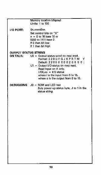
Memory location (display) Limits: 1 to 100
I/O PORT: Crn.nnnnEnn Set control bits on 3” n = 0 to 16 base 10 or ooootollll base2 if 0 then bit low if 1 then bit high
OUTPUT STATUS STRING ON TALK: UO = Output status word on next mad.
Format:220DFGJKPRTM Y Default:2200 0 00 02 0 6 0 0 :
Ul = Output l/O status on next read. Read input on X only. I/Oii,oo = I/O status where i is the input from 0 to 15. where o is the output from 0 to 15.
DEBUGGING JO = ROM and LED test Sets power up status byte, J to 1 in the status string.

PROGRAMS The following programs are designed to be a simple aid to the user, and are not intended to suit specific needs. Detailed information can be found in the manual and on the programming card.
HP 85
This program sets up the Model 220 output according to the values entered from the HP-85 keyboard, using the B2937A GPIB interface.
DiRECTiONS
1. Set switches on the Model 220 to addressable mode, primary address 12.
2. Connect the Model 220 to the HP 65 and HP 62937A GPIB interface.
3. Enter the program below using the END LINE key after each line. 4. Type RUN and depress the END LINE key. 5. The display will read ENTER I = . 6. To program the Model 220 to lfi output, type lE-6 and depress the
END LINE key. 7. The display will read ENTER V = . 8. To program the Model 220 to 20V compliance limit, type 20 and
depress END LINE key. 9. The programmed change can be verified by selecting one of the front
panel DISPLAY pushbuttons and reading the display value.
PROGRAM
10 REMOTE 712
20 DISP “ENTER I =” 30 INPUT I$
46 DISP “ENTER V = ” 50 lNPUTV$
60 OUTPUT 712;“ROPlFlX”, ‘7” I$ ‘II” vs’x”
0 GO’& 20’ 80 END
COMMENTS
Remote enable instrument at address 12.
Enter desired current. (Example: lfi = lE-6)
Enter desired voltage. (Example: 20V = 20). Output to IEEE bus, address 12.
Repeat End of program.
NOTE: While the program illustrates Model 220 programming over the bus, the same program may be used with the Model 230 by simply changing the bus address to 13 and entering 0, 1 or 2 (2mA, 2OmA or lOOmA) currant compliance in response to ENTER I.
77

HP 9825A This orooram sets up the Model 220 outrsut according to the values - entered from the HP 9825 keyboard, using the 98034AHPIB interface and a 9872A extended l/O ROM.
DIRECTIONS
1. Set switches on the Model 220 to addressable mode, primary address 12.
2. Connect the Model 220 to HP 9825A and 98034A HPIB interface. 3. Enter the program below, using the STORE key after each line. 4. Depress the RUN key. 5. The display will read: enter i = ?. 6. To program the Model 220 to 14 output, type lE-6 and depress the
STORE key. 7. The display will read: enter v = 7. &To program the Model 220 to 20V compliance limit, type 20 and
depress the STORE key. 9. The programmed change can be verified by selecting one of the front
panel DISPLAY pushbuttons and reading the display value.
PROGRAM COMMENTS 0 dim A$~201,I$1201,V$[201 Dimension string variables. 1 dev “220” 712
ent “enter’i = l”,lS Define bus address 12 as 220.
2 Enter desired currant. (Example: lfi = lE-6).
3 ent “enter v - 7” VS - , Enter desired voltage. (Example: 20V = 20).
4 “220“- A$ Set A$ = “220”. 5 wrt A$,“ROPlFlX” ’ “I”, Output to IEEE bus, address 12.
IS ‘II”V$ “X” 6 gto2’ ’ Repeat 7 end End of program.
NOTE: While the program illustrates Model 220 programming over the bus, the same program may be used with the Model 230 by simply changing the bus address to 13 and entering 0, 1 or 2 (2mA. 2OmA or lOOmA) current compliance in response to ENTER I.
12

HP 9845B This program sets up the Modal 220 output according to the values entered from the HPB845B keyboard using the 98034A HPIB interface and an I/O ROM.
DIRECTIONS
1. Set switches on the Model 220 to addressable mode, primary address 12.
2 Connect Model 220 to HP 98458 and 98034A interface. 3. Enter the program below using the STORE key after each line. 4. Depress the RUN key. 5. The display will mad “ENTER I” in the lower left corner. 6. To program the Model 220 to l&output, type lE-6 and depress the
STORE key. 7. The display will read ENTER V in the lower left hand corner. 8. To program the Model 220 to 20V compliance limit, type 20 and
depress the STORE key. 9. The programmed change can be verified by selecting one of the front
panel DISPLAY pushbuttons and reading the display value.
PROGRAM 10 DIM 1$(20), V$f20) 20 SRCE = 712 30 INPUT “ENTER I”, IS
COMMENTS Dimension string variables. Define bus address 12 as SRCE. Enter desired current. (Example: lfi = lE-6).
40 INPUT “ENTER V”,V$ Enter desired voltage. (Example: 20V = 20).
50 OUTPUT SRCE; “ROPlFlX”; Output to IEEE bus, address 12. “,“.I$.‘~“.Vs”x”
60GdTb3d Repeat 70 END NOTE: While the program illustrates Model 220 programming over the bus, the same program may be used with the Model 230 by simply changing the bus address to 13 entering 0, 1 or 2 QmA, 2OmA or lOOmAl current compliance in response to ENTER I.
13

APPLE II (APPLE Interface1
This program sets up the Model 220 output according to the values entered from the APPLE II keyboard.
DIRECTIONS
1. Set switches on the Model 220 to addressabe mode, primary address 12.
2. Connect the Modal 220 to APPLE II and APPLE IEEE interface. 3. Enter the program below using the RETURN key after each line. 4. Type in RUN. 5. The display will mad ENTER I. 6. To program the Model 220 to 14 output, type 1 E-6 and depress the
RETURN key. 7. The display will read ENTER V. 8. To program the Model 220 to ZOV compliance limit, type 20 and
depress the RETURN key. 9. The programmed change can be verified by selecting one of the front
panel DISPLAY pushbuttons and reading the display value.
PROGRAM 10 PRINT ENTER I 20 INPUT IS
30 PRINT ENTER V 40 INPUTVS
50 28 = CHRSf26) 60 PRW 70 IN#3 80 PRINT “RA” 90 PRINT “WT,“;Z$;“ROP1F1X”;
“pl$“qp”$.“x” ,, , I 100 PRINT “LFl”
110 PRt 0
120 INRO 130 GO TO 10 140 END
Sent remote enable all. Output to IEEE bus, address 12. Send line feed after carriage return. Set to I/O on the CRT Et keyboard.
Repeat End of program.
NOTE: While the program illustrates the Model 220 programming over the bus, the same program may be used with the Model 230 by simply changing the bus address to 13. Line 90 should read: 90 ‘?NT-“.ZB.“ROP,F,X”.“I”. I r , t
I$.‘q/“.“$.“x”. I ,I . Enter 0, 1 or 2 QmA, 20mA or lOOmA) current compliance is response to ENTER I.
74
COMMENTS
Enter desired current. (Example: Ifi = 156)
Enter desired voltage. (Example: 20V = 20). DefineZS = CTRL-2. Set to l/O on the IEEE bus.

PETKBM 2001
This program sets up the Model 220 output according to the values entered from the PETKBM 2001 keyboard.
DIRECTIONS
1. Sat switches on the Model 220 to addressable mode, primaly address 12.
2. Connect Model 220 to PETKBM 2001 IEEE interface. 3. Enter the program below using the RETURN key after each line. 4. Type RUN and depress the RETURN key. 5. The display will read ENTER I. 6. To program the Model 220 to lfi output, type lE-6 and depress the
RETURN key. 7. The display will read ENTER V. 8. To program the Model 220 to 20V compliance limit, type 20 and
depress the RETURN key. 9. The programmed change can be verified by selecting one of the front
panel DISPLAY pushbuttons and reading the display value.
PROGRAM 10 OPEN 6, 12 20 INPUT “ENTER I”; I$
30 INPUT “ENTER V”;V$
40 PRINT #6 “ROPlFlX” “I” l$,v~,vs:vc~ ’ ’
60 GOT0 20 80 END
COMMENTS Open file 6, primary address 12. Enter desired current. Example: lfi = lE-6) Entar desired voltage. (Example: 2OV = 20) Output to IEEE-488 bus, address 12.
Repeat End of program.
NOTE: While the program illustrates Model 220 programming over the bus, the same program may be usad with the Model 230 by simply changing the bus address to 13 and entering 0, 1 or 2 C?mA, 20mA or lOOmA) current compliance in response to ENTER I.
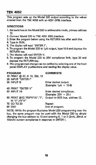
TEK 4052
This program sets up the Model 220 output according to the valuas entered from the TEK 4052 with an 4061 GPIB interface.
DIRECTIONS
1. Set switches on the Model 220 to addressable mode, primary address 12.
2 Connect Model 220 to TEK 4051 IEEE interface. 3. Enter the program below using the RETURN key after each line. 4. Type in RUN. 5. The display will read “ENTER l”. 6. To program the Model 220 to Ifi output, type 1 E-6and depress the
RETURN key. 7. The display will mad ENTER V. 8. To program the Model 220 to 2OV compliance limit, type 20 and
depress the RETURN key. 9. The programmed change can be verified by selecting one of the front
panel DISPLAY pushbuttons and reading the display value.
PROGRAM COMMENTS 10 PRINT @ 37,0: 10, 255, 13 20 INPUT “ENTER 1” 30 INPUT IS Enter desired output.
(Example: Ifi = lE-6) 40 PRINT “ENTER V” 50 INPUTVS Enter desired compliance.
(Example: 20V = 20.1 60 PRINT @l2:“ROP1FIX”,“I”, Output to IEEE bus, address 12.
IS ‘II” vs’x” 70 Gb TCi 20 Repeat 80 END End of program.
NOTE: While the program illustrates Model 220 programming over the bus, the same program may be used with the Model 230 by simply changing the bus address to 13 and entering 0, 1 or 2 QmA, 20mA or lOOmA) current compliance in response to ENTER I.
16

IBM PC or XT Personal Computer (Capital Equipment Corp. 01000 IEEE488 Interface)
The following program sends a command string to the Model 220/230 and displays the instrument data string on the IBM CRT. The equipment required for this program is the IBM PC or XT computer configured with DOS 2.0 and BASICA and the Capital Equipment Corp. (CEC) 01060 IEEE-488 interface. The interface board must be installed as per the CEC 01000 Instruction Manual (address = SCOOOO).
DIRECTIONS
1. Using the rear panel switches, set the Model 220/230 to the address- able mode with primary address 12.
2. Connect the instrument to the interface with power off. 3. Enter the program below into the computer, pressing the return key
after each line is entered. 4. Press the R key to run the program. The CRT will display
“COMMANDI”. 5. Enter the desired command string and press the return key. For exam-
ple, to program the Model 220 for a current of lOmA, key in llOE3X. To program a voltage of 25V on the Model 230, type in V25X.
6. The entire reading string from the instrument will then appear on the computer CRT.
PROGRAM
10 REM PROGRAM FOR MODEL 220 WITH CEC 01000 INTERFACE
20 CLS:DEF SEG = BHCOOO ‘INTERFACE IS AT ADDRESS scoooo
30 40
50 60 70
80 90
100
110
120 130
140
REM DEFINE INTERFACE PARAMETERS INIT = &ADD% = 21:LEV% =0: TRANSMIT =8:RECEIVE =6:REN$=“REN”:STATUS%=O R$=SPACE$tlOO) ’ DEFINE INPUT BUFFER CALL INITtADD%,LEV%) ‘INITIALIZE INTERFACE CALL TRANSMITfRENS,STATUS%) ‘SET UP THE 220 FOR REMOTE IF STATUS %C >O THEN 190 ’ IF BUS ERROR PROCESS IT INPUT “COMMAND”;CS ‘PROMPT FOR COMMAND CMD$=“MTA UNL LISTEN 12 DATA ’ “+Ct+“’ 13 IO” ‘SET UP LISTEN COMMAND CALL TRANSMIT (CMDS, STATUS%)’ TRANSMIT COMMAND TO 220 IF STATUS%00 THEN 190 CMD$=“MlA UNT TALK 12” ‘SET UP TALK COMMAND STRING CALL TRANSMIT (CMDS,STATUS%I’ADDRESS 220 TO TALK
17

150 IF STATUS%<70 THEN 190 160 CALL RECENE(R$,L%,STATUS%) ’ INPUT DATA STRING
FROM 220 170 PRINT LEFT$(R$,L%l ‘PRINT DATA STRING ON CRT 180 GOT0 90 ‘REPEAT 190 PRINT-IEEE ERROR #“;STATUS%:END ‘PROCESS IEEE
ERROR
18

IBM PC or XT Personal Computer ITecmar IEEE-488 Interface and Version 4.0 Software)
The following program sends a command string to the Model 220/230 and displays the instrument data string on the IBM CRT. The equipment required for this program is the IBM PC or XT computer configured with DOS 2.0 and BASICA and the Tecmar interface with version 4.0 soft- ware. The interface and associated software must be installed as per the Tecmar IEEE488 Instruction Manual (board address = EtH310).
DIRECTIONS 1. Using the rear panel switches, set the Model 220/230 for the address
able mode with primary address 12. 2. While power is off, connect the instrument to the interface. 3. Insert the Tecmar software disk in the default drive and load the pro-
gram called “IEEE488”. 4. Add the lines below to the front of the program, pressing return after
each line is entered. 5. Press the F2 key to run the program. The CRT will display
“COMMAND?“. 6. Enter the desired command strfng and press return. For example, to
program a current of 1OmA on the Model 220, enter IlOE-3X. To pro- gram a voltage of 25V on the Model 230, type in V25X.
7. The entire reading.string from the instrument will then appear on the CRT.
PROGRAM 5 CLS ’ PROGRAM FOR MODEL 220 AND TECMAR INTERFACE
WITH 4.0 SOFTWARE 10 PARAMS =“INIT/1/8H310/P/“:GOSUB 10000 ‘INITIALIZE
INTERFACE 20 PARAM$=“ADTR/“:GOSUB 10000 ’ SET UP 220 FOR
REMOTE 30 INPUT”COMMAND”;CMD$:IF CMD$=“” THEN 30 ‘PROMPT
FOR COMMAND 40 DATA.STRING$=CMD$ ‘SET UP INTERFACE COMMAND
STRING Xl PARAM$=‘WR.STR/12IIEOS/“:GOSUB 10000 ‘SEND
COMMAND STRING TO INSTRUMENT 60 ,PARAM$=“RD.STR/12/10/EOS/“:GOSUB 10000 ‘READ
DATA STRING FROM 220 70 PRINT DATA.STRING$ ‘PRINT DATA STRING ON CRT 90 GDTD 30 ‘REPEAT

E-H 7000 Computer The following program sends a data string from the E-H 7066 computer to the Modal 220/230 and then displays theinstruments reading on the computer CRT. The E-H 7000 must be configured with MS-DOS, IO-SYS and BASICA as outlined in its instruction manual.
DIRECTIONS
1. Using the rear panel switches, set the Modal 220/230 for the addressable mode with priman/ address 12.
2. While the power is off connect the Model 220/230 to PORT 1 of the computer.
3. While in BASICA, tYpe LOAD “EHE488.CMP” to load the GPIB handler software.
4. Add the lines below to the front of the program now in memory; press the return key after each line is typed. The complete program may now be saved in the usual manner.
5. Press the computer F2 key to run the program. The CRT will prompt with “COMMAND?“.
6. Type in the desired command. For example, to program a current of 1OmA on the Model 220, enter IlOE-3X. To program a voltage of 25V on the Model 230 type in V26X and press the return key.
7. The entire reading string from the instrument will then appear on the CRT.
PROGRAM 10 CLS 20 GOSUB 65010 30 CALL PORT1 40 CALL INlT 50 DEVS = “12 ” 60 INPUT “COMMAND”; C8
70 IF C$=““THEN 60 80 INS = SPACES(60) 90 CALL SNDSTR(DEVS,CS)
100 CALL RCVSTRfDEVS, INS)
110 PRINT INS
120 GOTD 66
COMMENTS
‘Initialize Handler Software ‘Initialize Port 1 ‘Initialize Interface ‘Primary Address = 12 ‘Prompt for Command String
’ If Null Input Go Back ’ Define Reading Buffer ’ Send Command String to
220 ‘Get Reading From 220
‘Display Reading String on CRT
‘Repeat

Test Instrumentation Group 28775 Aurora Road / Cleveland, Ohio 44139
![VSA EKO - Øland Online · VSA 225 EKO: VSA 250 EKO: 190 EKO: 220 EKO 225 EKO: 250 EKO: Voltage/Frequency [V/Hz] 230/50: 230/50 230/50: 230/50 Power consumption [kW] 0,084: 0,097](https://static.fdocuments.us/doc/165x107/5f37a3a97f20d670052cfa53/vsa-eko-land-online-vsa-225-eko-vsa-250-eko-190-eko-220-eko-225-eko-250.jpg)


