Model 2002 Multimeter User's Manual
361
Model 2002 Multimeter User’s Manual Contains Operating and Servicing Information
Transcript of Model 2002 Multimeter User's Manual

Model 2002Multimeter
User’s Manual
Contains Operating and Servicing Information

WARRANTY
Keithley Instruments, Inc. warrants this product to be free from defects in material and workmanship for a period of 3 years fromdate of shipment.
Keithley Instruments, Inc. warrants the following items for 90 days from the date of shipment: probes, cables, rechargeable batteries,diskettes, and documentation.
During the warranty period, we will, at our option, either repair or replace any product that proves to be defective.
To exercise this warranty, write or call your local Keithley representative, or contact Keithley headquarters in Cleveland, Ohio. Youwill be given prompt assistance and return instructions. Send the product, transportation prepaid, to the indicated service facility.Repairs will be made and the product returned, transportation prepaid. Repaired or replaced products are warranted for the balanceof the original warranty period, or at least 90 days.
LIMITATION OF WARRANTY
This warranty does not apply to defects resulting from product modification without Keithley’s express written consent, or misuseof any product or part. This warranty also does not apply to fuses, software, non-rechargeable batteries, damage from battery leak-age, or problems arising from normal wear or failure to follow instructions.
THIS WARRANTY IS IN LIEU OF ALL OTHER WARRANTIES, EXPRESSED OR IMPLIED, INCLUDING ANY IMPLIEDWARRANTY OF MERCHANTABILITY OR FITNESS FOR A PARTICULAR USE. THE REMEDIES PROVIDED HEREINARE BUYER’S SOLE AND EXCLUSIVE REMEDIES.
NEITHER KEITHLEY INSTRUMENTS, INC. NOR ANY OF ITS EMPLOYEES SHALL BE LIABLE FOR ANY DIRECT,INDIRECT, SPECIAL, INCIDENTAL OR CONSEQUENTIAL DAMAGES ARISING OUT OF THE USE OF ITS INSTRU-MENTS AND SOFTWARE EVEN IF KEITHLEY INSTRUMENTS, INC., HAS BEEN ADVISED IN ADVANCE OF THE POS-SIBILITY OF SUCH DAMAGES. SUCH EXCLUDED DAMAGES SHALL INCLUDE, BUT ARE NOT LIMITED TO: COSTSOF REMOVAL AND INSTALLATION, LOSSES SUSTAINED AS THE RESULT OF INJURY TO ANY PERSON, OR DAM-AGE TO PROPERTY.
Keithley Instruments, Inc.
• 28775 Aurora Road • Cleveland, OH 44139 • 440-248-0400 • Fax: 440-248-6168 • http://www.keithley.com
BELGIUM: Keithley Instruments B.V.
Bergensesteenweg 709 • B-1600 Sint-Pieters-Leeuw • 02/363 00 40 • Fax: 02/363 00 64
CHINA: Keithley Instruments China
Yuan Chen Xin Building, Room 705 • 12 Yumin Road, Dewai, Madian • Beijing 100029 • 8610-62022886 • Fax: 8610-62022892
FRANCE: Keithley Instruments Sarl
B.P. 60 • 3, allée des Garays • 91122 Palaiseau Cédex • 01 64 53 20 20 • Fax: 01 60 11 77 26
GERMANY: Keithley Instruments GmbH
Landsberger Strasse 65 • D-82110 Germering • 089/84 93 07-40 • Fax: 089/84 93 07-34
GREAT BRITAIN: Keithley Instruments Ltd
The Minster • 58 Portman Road • Reading, Berkshire RG30 1EA • 0118-9 57 56 66 • Fax: 0118-9 59 64 69
INDIA: Keithley Instruments GmbH
Flat 2B, WILOCRISSA • 14, Rest House Crescent • Bangalore 560 001 • 91-80-509-1320/21 • Fax: 91-80-509-1322
ITALY: Keithley Instruments s.r.l.
Viale S. Gimignano, 38 • 20146 Milano • 02/48 30 30 08 • Fax: 02/48 30 22 74
NETHERLANDS: Keithley Instruments B.V.
Postbus 559 • 4200 AN Gorinchem • 0183-635333 • Fax: 0183-630821
SWITZERLAND: Keithley Instruments SA
Kriesbachstrasse 4 • 8600 Dübendorf • 01-821 94 44 • Fax: 01-820 30 81
TAIWAN: Keithley Instruments Taiwan
1 Fl. 85 Po Ai Street • Hsinchu, Taiwan, R.O.C. • 886-3572-9077• Fax: 886-3572-9031
6/99

Model 2002 MultimeterUser’s Manual
©1994, Keithley Instruments, Inc.All rights reserved.
Cleveland, Ohio, U.S.A.Fourth Printing, March 1999
Document Number: 2002-900-01 Rev. D

Manual Print History
The print history shown below lists the printing dates of all Revisions and Addenda created for this manual. The RevisionLevel letter increases alphabetically as the manual undergoes subsequent updates. Addenda, which are released between Revi-sions, contain important change information that the user should incorporate immediately into the manual. Addenda are num-bered sequentially. When a new Revision is created, all Addenda associated with the previous Revision of the manual areincorporated into the new Revision of the manual. Each new Revision includes a revised copy of this print history page.
Revision A (Document Number 2002-900-01)......................................................................................... May 1994Addendum A (Document Number 2002-900-02) ..................................................................................... May 1995Addendum A (Document Number 2002-900-03) ................................................................................October 1995Addendum A (Document Number 2002-900-04) .................................................................................. March 1996Revision B (Document Number 2002-900-01)............................................................................... September 1997Revision C (Document Number 2002-900-01)......................................................................................... June 1998Revision D (Document Number 2002-900-01) ..................................................................................... March 1999
All Keithley product names are trademarks or registered trademarks of Keithley Instruments, Inc.Other brand and product names are trademarks or registered trademarks of their respective holders

Safety Precautions
The following safety precautions should be observed before usingthis product and any associated instrumentation. Although some in-struments and accessories would normally be used with non-haz-ardous voltages, there are situations where hazardous conditionsmay be present.
This product is intended for use by qualified personnel who recog-nize shock hazards and are familiar with the safety precautions re-quired to avoid possible injury. Read the operating informationcarefully before using the product.
The types of product users are:
Responsible body
is the individual or group responsible for the useand maintenance of equipment, for ensuring that the equipment isoperated within its specifications and operating limits, and for en-suring that operators are adequately trained.
Operators
use the product for its intended function. They must betrained in electrical safety procedures and proper use of the instru-ment. They must be protected from electric shock and contact withhazardous live circuits.
Maintenance personnel
perform routine procedures on the productto keep it operating, for example, setting the line voltage or replac-ing consumable materials. Maintenance procedures are described inthe manual. The procedures explicitly state if the operator may per-form them. Otherwise, they should be performed only by servicepersonnel.
Service personnel
are trained to work on live circuits, and performsafe installations and repairs of products. Only properly trained ser-vice personnel may perform installation and service procedures.
Exercise extreme caution when a shock hazard is present. Lethalvoltage may be present on cable connector jacks or test fixtures. TheAmerican National Standards Institute (ANSI) states that a shockhazard exists when voltage levels greater than 30V RMS, 42.4Vpeak, or 60VDC are present.
A good safety practice is to expectthat hazardous voltage is present in any unknown circuit beforemeasuring.
Users of this product must be protected from electric shock at alltimes. The responsible body must ensure that users are preventedaccess and/or insulated from every connection point. In some cases,connections must be exposed to potential human contact. Productusers in these circumstances must be trained to protect themselvesfrom the risk of electric shock. If the circuit is capable of operatingat or above 1000 volts,
no conductive part of the circuit may beexposed.
As described in the International Electrotechnical Commission(IEC) Standard IEC 664, digital multimeter measuring circuits(e.g., Keithley Models 175A, 199, 2000, 2001, 2002, and 2010) areInstallation Category II. All other instruments’ signal terminals areInstallation Category I and must not be connected to mains.
Do not connect switching cards directly to unlimited power circuits.They are intended to be used with impedance limited sources.NEVER connect switching cards directly to AC mains. When con-necting sources to switching cards, install protective devices to lim-it fault current and voltage to the card.
Before operating an instrument, make sure the line cord is connect-ed to a properly grounded power receptacle. Inspect the connectingcables, test leads, and jumpers for possible wear, cracks, or breaksbefore each use.
For maximum safety, do not touch the product, test cables, or anyother instruments while power is applied to the circuit under test.ALWAYS remove power from the entire test system and dischargeany capacitors before: connecting or disconnecting cables or jump-ers, installing or removing switching cards, or making internalchanges, such as installing or removing jumpers.
Do not touch any object that could provide a current path to thecommon side of the circuit under test or power line (earth) ground.Always make measurements with dry hands while standing on adry, insulated surface capable of withstanding the voltage beingmeasured.

The instrument and accessories must be used in accordance with itsspecifications and operating instructions or the safety of the equip-ment may be impaired.
Do not exceed the maximum signal levels of the instruments and ac-cessories, as defined in the specifications and operating informa-tion, and as shown on the instrument or test fixture panels, orswitching card.
When fuses are used in a product, replace with same type and ratingfor continued protection against fire hazard.
Chassis connections must only be used as shield connections formeasuring circuits, NOT as safety earth ground connections.
If you are using a test fixture, keep the lid closed while power is ap-plied to the device under test. Safe operation requires the use of alid interlock.
If a screw is present, connect it to safety earth ground using thewire recommended in the user documentation.
The symbol on an instrument indicates that the user should re-fer to the operating instructions located in the manual.
The symbol on an instrument shows that it can source or mea-sure 1000 volts or more, including the combined effect of normaland common mode voltages. Use standard safety precautions toavoid personal contact with these voltages.
The
WARNING
heading in a manual explains dangers that mightresult in personal injury or death. Always read the associated infor-mation very carefully before performing the indicated procedure.
The
CAUTION
heading in a manual explains hazards that coulddamage the instrument. Such damage may invalidate the warranty.
Instrumentation and accessories shall not be connected to humans.
Before performing any maintenance, disconnect the line cord andall test cables.
To maintain protection from electric shock and fire, replacementcomponents in mains circuits, including the power transformer, testleads, and input jacks, must be purchased from Keithley Instru-ments. Standard fuses, with applicable national safety approvals,may be used if the rating and type are the same. Other componentsthat are not safety related may be purchased from other suppliers aslong as they are equivalent to the original component. (Note that se-lected parts should be purchased only through Keithley Instrumentsto maintain accuracy and functionality of the product.) If you areunsure about the applicability of a replacement component, call aKeithley Instruments office for information.
To clean an instrument, use a damp cloth or mild, water basedcleaner. Clean the exterior of the instrument only. Do not applycleaner directly to the instrument or allow liquids to enter or spillon the instrument. Products that consist of a circuit board with nocase or chassis (e.g., data acquisition board for installation into acomputer) should never require cleaning if handled according to in-structions. If the board becomes contaminated and operation is af-fected, the board should be returned to the factory for propercleaning/servicing.
!
Rev. 2/99

Table of Contents
1 General Information
1.1 Introduction ........................................................................................................................................................ 1-11.2 Features .............................................................................................................................................................. 1-11.3 Warranty information ......................................................................................................................................... 1-21.4 Manual addenda ................................................................................................................................................. 1-21.5 Safety symbols and terms .................................................................................................................................. 1-21.6 Specifications ..................................................................................................................................................... 1-21.7 Inspection ........................................................................................................................................................... 1-21.8 Options and accessories ..................................................................................................................................... 1-2
2 Front Panel Operation
2.1 Introduction ........................................................................................................................................................ 2-12.2 Power-up ............................................................................................................................................................ 2-12.2.1 Line power connections ............................................................................................................................. 2-12.2.2 Line fuse replacement ................................................................................................................................ 2-22.2.3 Power-up sequence .................................................................................................................................... 2-22.2.4 High energy circuit safety precautions ....................................................................................................... 2-42.2.5 Power-on default conditions ...................................................................................................................... 2-42.2.6 Warm-up period ......................................................................................................................................... 2-42.2.7 IEEE-488 primary address ......................................................................................................................... 2-42.3 Display ............................................................................................................................................................... 2-42.3.1 Multiple displays ........................................................................................................................................ 2-42.3.2 Information messages ................................................................................................................................ 2-72.3.3 Status and error messages .......................................................................................................................... 2-72.3.4 Navigating menus ...................................................................................................................................... 2-92.4 Functions ............................................................................................................................................................ 2-92.4.1 DC and AC voltage .................................................................................................................................... 2-92.4.2 DC and AC current .................................................................................................................................. 2-232.4.3 Two and four-wire resistance ................................................................................................................... 2-282.4.4 Frequency ................................................................................................................................................. 2-322.4.5 Temperature ............................................................................................................................................. 2-332.5 Range ............................................................................................................................................................... 2-402.5.1 Display resolution .................................................................................................................................... 2-402.5.2 Maximum readings .................................................................................................................................. 2-402.5.3 Manual ranging ........................................................................................................................................ 2-402.5.4 Autoranging ............................................................................................................................................. 2-402.6 Relative ............................................................................................................................................................ 2-402.6.1 Configuring rel ......................................................................................................................................... 2-412.6.2 Enabling rel .............................................................................................................................................. 2-41
i

2.6.3 Multiple display of rel .............................................................................................................................. 2-412.7 Triggers ............................................................................................................................................................. 2-412.7.1 Trigger model ........................................................................................................................................... 2-412.7.2 Configuring the measure layer ................................................................................................................. 2-462.7.3 Configuring the scan layer ........................................................................................................................ 2-482.7.4 Configuring the arm layer ........................................................................................................................ 2-492.7.5 Halting triggers ......................................................................................................................................... 2-502.7.6 External triggering .................................................................................................................................... 2-502.7.7 Trigger Link .............................................................................................................................................. 2-532.8 Buffer ................................................................................................................................................................ 2-642.8.1 Burst mode ................................................................................................................................................ 2-652.8.2 Configuring data storage .......................................................................................................................... 2-672.8.3 Storing and recalling readings .................................................................................................................. 2-692.8.4 Buffer multiple displays ........................................................................................................................... 2-702.9 Filter ................................................................................................................................................................. 2-712.9.1 Filter types ................................................................................................................................................ 2-712.9.2 Filter modes .............................................................................................................................................. 2-712.9.3 Response time ........................................................................................................................................... 2-732.9.4 Auto filtering ............................................................................................................................................ 2-732.9.5 Configuring the filters .............................................................................................................................. 2-742.10 Math .................................................................................................................................................................. 2-752.10.1 Polynomial ................................................................................................................................................ 2-752.10.2 Percent ...................................................................................................................................................... 2-762.10.3 Percent deviation ...................................................................................................................................... 2-762.10.4 Selecting and configuring math ................................................................................................................ 2-762.10.5 Calculate multiple display ........................................................................................................................ 2-772.11 Scanning ........................................................................................................................................................... 2-772.11.1 Scanning overview ................................................................................................................................... 2-772.11.2 Front panel scanner controls ..................................................................................................................... 2-772.11.3 Using CHAN key to close and open internal channels ............................................................................ 2-782.11.4 Using CONFIGURE CHAN to configure channels ................................................................................. 2-792.11.5 Using CONFIG-SCAN to configure scanning ......................................................................................... 2-802.11.6 Using SCAN to configure scan parameters .............................................................................................. 2-812.11.7 Starting and stopping scanning ................................................................................................................. 2-832.11.8 Scanner operation examples ..................................................................................................................... 2-832.12 Menu ................................................................................................................................................................. 2-872.12.1 SAVESETUP ........................................................................................................................................... 2-902.12.2 GPIB ......................................................................................................................................................... 2-962.12.3 CALIBRATION ....................................................................................................................................... 2-962.12.4 TEST ......................................................................................................................................................... 2-972.12.5 LIMITS ..................................................................................................................................................... 2-972.12.6 STATUS-MSG ......................................................................................................................................... 2-992.12.7 GENERAL ............................................................................................................................................... 2-99
3 IEEE-488 Reference
3.1 Introduction ........................................................................................................................................................ 3-13.2 IEEE-488 bus connections ................................................................................................................................. 3-13.3 Primary address selection ................................................................................................................................... 3-23.4 QuickBASIC 4.5 programming .......................................................................................................................... 3-33.5 General bus commands ....................................................................................................................................... 3-43.5.1 REN (remote enable) .................................................................................................................................. 3-43.5.2 IFC (interface clear) ................................................................................................................................... 3-4
ii
3.5.3 LLO (local lockout) ................................................................................................................................... 3-43.5.4 GTL (go to local) ....................................................................................................................................... 3-53.5.5 DCL (device clear) ..................................................................................................................................... 3-53.5.6 SDC (selective device clear) ...................................................................................................................... 3-53.5.7 GET (group execute trigger) ...................................................................................................................... 3-53.5.8 SPE, SPD (serial polling) ........................................................................................................................... 3-53.6 Front panel aspects of IEEE-488 operation ....................................................................................................... 3-53.6.1 Error and status message ............................................................................................................................ 3-53.6.2 IEEE-488 status indicators ......................................................................................................................... 3-53.6.3 LOCAL key ................................................................................................................................................ 3-63.7 Status structure ................................................................................................................................................... 3-63.7.1 Condition registers ..................................................................................................................................... 3-83.7.2 Transition filters ......................................................................................................................................... 3-83.7.3 Event registers ............................................................................................................................................ 3-83.7.4 Enable registers .......................................................................................................................................... 3-83.7.5 Queues ...................................................................................................................................................... 3-163.7.6 Status byte and service request (SRQ) ..................................................................................................... 3-163.8 Trigger model (IEEE-488 operation) ............................................................................................................... 3-183.9 Programming syntax ........................................................................................................................................ 3-233.10 Common commands ........................................................................................................................................ 3-293.10.1 *CLS — clear status ................................................................................................................................ 3-293.10.2 *ESE <NRf> — event enable .................................................................................................................. 3-30
*ESE? — event enable query ................................................................................................................... 3-303.10.3 *ESR? — event status register query ....................................................................................................... 3-313.10.4 *IDN? — identification query ................................................................................................................. 3-323.10.5 *OPC — operation complete ................................................................................................................... 3-333.10.6 *OPC? — operation complete query ....................................................................................................... 3-343.10.7 *OPT? — option identification query ...................................................................................................... 3-353.10.8 *RCL — recall ......................................................................................................................................... 3-353.10.9 *RST — reset ........................................................................................................................................... 3-363.10.10 *SAV — save ........................................................................................................................................... 3-363.10.11 *SRE <NRf> — service request enable ................................................................................................... 3-36
*SRE? — service request enable query ................................................................................................... 3-363.10.12 *STB? — status byte query ..................................................................................................................... 3-383.10.13 *TRG — trigger ....................................................................................................................................... 3-393.10.14 *TST? — self-test query .......................................................................................................................... 3-393.10.15 *WAI — wait-to-continue ....................................................................................................................... 3-403.11 Signal oriented measurement commands ......................................................................................................... 3-413.12 Calculate subsystem ......................................................................................................................................... 3-673.12.1 :CALCulate[1] ......................................................................................................................................... 3-673.12.2 :CALCulate2 ............................................................................................................................................ 3-693.12.3 :CALCulate3 ............................................................................................................................................ 3-713.13 :DISPlay subsystem ......................................................................................................................................... 3-763.14 :FORMat subsystem ......................................................................................................................................... 3-793.15 :INPut subsystem ............................................................................................................................................. 3-843.16 :OUTPut subsystem ......................................................................................................................................... 3-853.17 :ROUTe subsystem .......................................................................................................................................... 3-863.17.1 :CLOSe <list> .......................................................................................................................................... 3-863.17.2 :OPEN <list> ............................................................................................................................................ 3-863.17.3 :OPEN:ALL ............................................................................................................................................. 3-873.17.4 :SCAN commands .................................................................................................................................... 3-873.18 Sense subsystems ............................................................................................................................................. 3-913.18.1 [:SENSe[1]] subsystem ............................................................................................................................ 3-913.18.2 :ALTernate[1] commands ........................................................................................................................ 3-91
iii
3.18.3 :FUNCtion <name> .................................................................................................................................. 3-913.18.4 :DATA commands .................................................................................................................................... 3-923.18.5 :APERture <n> ......................................................................................................................................... 3-933.18.6 :NPLCycles <n> ....................................................................................................................................... 3-943.18.7 :COUPling AC|DC ................................................................................................................................... 3-963.18.8 RANGe commands ................................................................................................................................... 3-963.18.9 :REFerence <n> ........................................................................................................................................ 3-993.18.10 :DIGits <n> ............................................................................................................................................. 3-1013.18.11 :AVERage commands ............................................................................................................................ 3-1023.18.12 [:FUNCTION] <name> .......................................................................................................................... 3-1053.18.13 :PWINdow <n> ...................................................................................................................................... 3-1063.18.14 :METHod <name> ................................................................................................................................. 3-1063.18.15 :SOURce <name> ................................................................................................................................... 3-1063.18.16 THReshold commands ........................................................................................................................... 3-1073.18.17 :TRANsducer <name> ........................................................................................................................... 3-1083.18.18 :RTD commands ..................................................................................................................................... 3-1093.18.19 :TCouple:TYPE <name> ........................................................................................................................ 3-1113.18.20 :RJUNctionX commands ........................................................................................................................ 3-1123.18.21 :OCOMpensated <b> ............................................................................................................................. 3-1143.18.22 :DTCouple commands ............................................................................................................................ 3-1143.18.23 :SENSe2 subsystem ................................................................................................................................ 3-1153.19 :SOURce subsystem ....................................................................................................................................... 3-1163.20 :STATus subsystem ........................................................................................................................................ 3-1173.20.1 [:EVENt]? ............................................................................................................................................... 3-1173.20.2 :ENABle <NRf> ..................................................................................................................................... 3-1223.20.3 :PTRansition <NRf> ............................................................................................................................... 3-1253.20.4 :NTRansition <NRf> .............................................................................................................................. 3-1323.20.5 :CONDition? ........................................................................................................................................... 3-1343.20.6 :PRESET ................................................................................................................................................. 3-1343.20.7 :QUEue commands ................................................................................................................................. 3-1353.21 :SYSTem subsystem ....................................................................................................................................... 3-1373.21.1 :PRESet ................................................................................................................................................... 3-1373.21.2 :POSetup <name> ................................................................................................................................... 3-1373.21.3 :FRSWitch? ............................................................................................................................................ 3-1373.21.4 :VERSion? .............................................................................................................................................. 3-1383.21.5 :ERRor? .................................................................................................................................................. 3-1383.21.6 :AZERo commands ................................................................................................................................ 3-1383.21.7 :AMEThod <name> ............................................................................................................................... 3-1393.21.8 :LSYNc:STATe <b> .............................................................................................................................. 3-1433.21.9 :KEY <NRf> .......................................................................................................................................... 3-1433.21.10 :CLEar .................................................................................................................................................... 3-1453.21.11 :LFRequency .......................................................................................................................................... 3-1453.21.12 :DATE <yr>, <mo>, <day> .................................................................................................................... 3-1453.21.13 :TIME <hr>, <min>, <sec> .................................................................................................................... 3-1453.21.14 :TSTamp commands ............................................................................................................................... 3-1463.21.15 :RNUMber:RESet ................................................................................................................................... 3-1463.22 :TRACe subsystem ......................................................................................................................................... 3-1473.22.1 :CLEar .................................................................................................................................................... 3-1473.22.2 :FREE? ................................................................................................................................................... 3-1473.22.3 :EGRoup <name> ................................................................................................................................... 3-1473.22.4 :POINts <n> ........................................................................................................................................... 3-1483.22.5 :FEED <name> ....................................................................................................................................... 3-1483.22.6 :DATA? .................................................................................................................................................. 3-1513.22.7 :TSTamp:FORMat <name> ................................................................................................................... 3-151
iv

3.23 Trigger subsystem .......................................................................................................................................... 3-1523.23.1 :INITiate commands .............................................................................................................................. 3-1523.23.2 :ABORt .................................................................................................................................................. 3-1523.23.3 :IMMediate ............................................................................................................................................. 3-1523.23.4 :COUNt <n> ........................................................................................................................................... 3-1533.23.5 :DELay <n> ............................................................................................................................................ 3-1533.23.6 :SOURce <name> .................................................................................................................................. 3-1543.23.7 :TIMer <n> ............................................................................................................................................. 3-1543.23.8 :SIGNal .................................................................................................................................................. 3-1553.23.9 TCONfigure commands ......................................................................................................................... 3-1553.23.10 RTCLock commands ............................................................................................................................. 3-1573.24 :UNIT subsystem ........................................................................................................................................... 3-159
A Specifications
B Interface Function Codes
C ASCII Character Codes and IEEE-488 Multiline Interface Command Messages
D IEEE-488 Bus Overview
E IEEE-488 Conformance Information
F SCPI Conformance Information
G Example Programs
H HP3458A Emulation Mode
v

List of Illustrations
2 Front Panel Operation
Figure 2-1 Bar graph (zero-at-left) multiple display .................................................................................................... 2-6Figure 2-2 Zero-centered bar graph multiple display .................................................................................................. 2-6Figure 2-3 Maximum and minimum multiple display ................................................................................................. 2-7Figure 2-4 Positive and negative peak spikes ............................................................................................................ 2-15Figure 2-5 DC voltage multifunction multiple displays ............................................................................................ 2-16Figure 2-6 AC voltage multifunction multiple displays ............................................................................................ 2-20Figure 2-7 DC in-circuit current measurements ........................................................................................................ 2-26Figure 2-8 AC current multifunction multiple displays ............................................................................................. 2-28Figure 2-9 3-wire RTD temperature measurements .................................................................................................. 2-34Figure 2-10 2-wire RTD temperature measurements .................................................................................................. 2-35Figure 2-11 Temperature equations ............................................................................................................................. 2-38Figure 2-12 Trigger model (front panel operation) ...................................................................................................... 2-44Figure 2-13 External triggering connectors (BNC) ..................................................................................................... 2-50Figure 2-14 External triggering and asynchronous trigger link input pulse specifications ......................................... 2-50Figure 2-15 Meter complete and asynchronous trigger link output pulse specifications ............................................ 2-51Figure 2-16 DUT test system ....................................................................................................................................... 2-51Figure 2-17 External trigger connectors ...................................................................................................................... 2-52Figure 2-18 Trigger link connectors ............................................................................................................................ 2-53Figure 2-19 DUT test system ....................................................................................................................................... 2-54Figure 2-20 Trigger Link connections (asynchronous example #1) ............................................................................ 2-54Figure 2-21 Operation model for asynchronous trigger link example #1 .................................................................... 2-56Figure 2-22 Connections using Trigger Link adapter .................................................................................................. 2-57Figure 2-23 DUT test system (asynchronous example #2) .......................................................................................... 2-57Figure 2-24 Trigger Link connections (asynchronous example #2) ............................................................................ 2-58Figure 2-25 Operation model for asynchronous Trigger Link example #2 ................................................................. 2-60Figure 2-26 Semi-synchronous Trigger Link specifications ....................................................................................... 2-61Figure 2-27 Typical semi-synchronous mode connections ......................................................................................... 2-61Figure 2-28 Trigger Link connections (semi-synchronous example) .......................................................................... 2-62Figure 2-29 Operation mode for semi-synchronous Trigger Link example ................................................................ 2-63Figure 2-30 Averaging and advanced filter types ........................................................................................................ 2-72Figure 2-31 Moving and repeating filter modes .......................................................................................................... 2-73Figure 2-32 SCAN key menu structure ....................................................................................................................... 2-82Figure 2-33 SCAN key menu structure for ratio and delta .......................................................................................... 2-83Figure 2-34 Limits bar graph example ........................................................................................................................ 2-98Figure 2-35 Using limit test to start 100
Ω
resistor ...................................................................................................... 2-99Figure 2-36 Digital I/O port ....................................................................................................................................... 2-100Figure 2-37 Digital I/O port simplified schematic ..................................................................................................... 2-101Figure 2-38 Sample externally powered relay sample ............................................................................................... 2-102Figure 2-39 Line cycle synchronization .................................................................................................................... 2-104
vii

3 IEEE-488 Reference
Figure 3-1 IEEE-488 connector ................................................................................................................................... 3-2Figure 3-2 IEEE-488 connections ................................................................................................................................ 3-2Figure 3-3 IEEE-488 connector location ..................................................................................................................... 3-2Figure 3-4 Model 2002 status register structure ........................................................................................................... 3-7Figure 3-5 Standard event status .................................................................................................................................. 3-9Figure 3-6 Operation event status .............................................................................................................................. 3-10Figure 3-7 Arm event status ....................................................................................................................................... 3-11Figure 3-8 Sequence event status ............................................................................................................................... 3-12Figure 3-9 Trigger event status .................................................................................................................................. 3-13Figure 3-10 Measurement event status ......................................................................................................................... 3-14Figure 3-11 Questionable event status ......................................................................................................................... 3-15Figure 3-12 Status byte and service request (SRQ) ..................................................................................................... 3-17Figure 3-13 Trigger Model (IEEE-488 bus operation) ................................................................................................ 3-19Figure 3-14 Standard Event Enable Register ............................................................................................................... 3-31Figure 3-15 Standard Event Status Register ................................................................................................................ 3-32Figure 3-16 Service Request Enable Register .............................................................................................................. 3-37Figure 3-17 Status Byte Register ................................................................................................................................. 3-39Figure 3-18 ASCII data format .................................................................................................................................... 3-79Figure 3-19 IEEE754 single precision data format (32 data bits) ................................................................................ 3-80Figure 3-20 IEEE754 double precision data format (64 data bits) .............................................................................. 3-81Figure 3-21 Measurement Event Register .................................................................................................................. 3-118Figure 3-22 Questionable Event Register .................................................................................................................. 3-119Figure 3-23 Operation Event Register ....................................................................................................................... 3-120Figure 3-24 Trigger Event Register ........................................................................................................................... 3-120Figure 3-25 Arm Event Register ................................................................................................................................ 3-121Figure 3-26 Sequence Event Register ........................................................................................................................ 3-121Figure 3-27 Measurement Event Enable Register ...................................................................................................... 3-123Figure 3-28 Questionable Event Enable Register ...................................................................................................... 3-123Figure 3-29 Operation Event Enable Register ........................................................................................................... 3-124Figure 3-30 Trigger Event Enable Register ............................................................................................................... 3-124Figure 3-31 Arm Event Enable Register .................................................................................................................... 3-124Figure 3-32 Sequence Event Enable Register ............................................................................................................ 3-125Figure 3-33 Measurement Transition Filter ............................................................................................................... 3-126Figure 3-34 Questionable Transition Filter ................................................................................................................ 3-127Figure 3-35 Operation Transition Filter ..................................................................................................................... 3-128Figure 3-36 Trigger Transition Filter ......................................................................................................................... 3-129Figure 3-37 Arm Transition Filter .............................................................................................................................. 3-130Figure 3-38 Sequence Transition Filter ...................................................................................................................... 3-131Figure 3-39 Key-press codes ...................................................................................................................................... 3-144
D IEEE-488 Bus Overview
Figure D-1 IEEE-488 bus configuration ...................................................................................................................... D-2Figure D-2 IEEE-488 handshake sequence .................................................................................................................. D-3Figure D-3 Command codes ........................................................................................................................................ D-6
viii
List of Tables
2 Front Panel Operation
Table 2-1 Data checked on power-up ......................................................................................................................... 2-3Table 2-2 Power-up error messages ........................................................................................................................... 2-3Table 2-3 Multiple displays by function .................................................................................................................... 2-5Table 2-4 Status and error messages .......................................................................................................................... 2-8Table 2-5 EXIT key actions ....................................................................................................................................... 2-9Table 2-6 CONFIGURE DCV menu structure ........................................................................................................ 2-10Table 2-7 CONFIGURE ACV menu structure ........................................................................................................ 2-11Table 2-8 DCV and ACV integration times set-by-resolution ................................................................................. 2-12Table 2-9 DCV and ACV auto filter ........................................................................................................................ 2-13Table 2-10 DCV and ACV auto resolution ................................................................................................................ 2-13Table 2-11 CONFIGURE DCI menu structure .......................................................................................................... 2-24Table 2-12 CONFIGURE ACI menu structure .......................................................................................................... 2-24Table 2-13 DCI and ACI integration time set-by-resolution ...................................................................................... 2-25Table 2-14 DCI and ACI auto filter ........................................................................................................................... 2-25Table 2-15 DCI and ACI auto resolution ................................................................................................................... 2-26Table 2-16 CONFIGURE OHMS-2W menu structure .............................................................................................. 2-29Table 2-17 CONFIGURE OHMS-4W menu structure .............................................................................................. 2-29Table 2-18
Ω
2 and
Ω
4 integration time set-by-resolution ......................................................................................... 2-30Table 2-19
Ω
2 and
Ω
4 auto filter ............................................................................................................................... 2-30Table 2-20
Ω
2 and
Ω
4 auto resolution ....................................................................................................................... 2-31Table 2-21 Trigger level range and increments .......................................................................................................... 2-32Table 2-22 CONFIGURE FREQUENCY menu structure ......................................................................................... 2-33Table 2-23 CONFIG TEMPERATURE menu structure ............................................................................................ 2-36Table 2-24 Temperature integration time set-by-resolution ....................................................................................... 2-39Table 2-25 Temperature auto resolution .................................................................................................................... 2-39Table 2-26 Allowable rel values ................................................................................................................................. 2-41Table 2-27 CONFIGURE TRIGGER menu structure ................................................................................................ 2-42Table 2-28 Reading storage options ........................................................................................................................... 2-64Table 2-29 CONFIGURE DATA STORE menu structure ........................................................................................ 2-65Table 2-30 Available functions in burst mode ........................................................................................................... 2-66Table 2-31 Burst mode sequence ............................................................................................................................... 2-67Table 2-32 Fill-and-stop sequence ............................................................................................................................. 2-69Table 2-33 Continuous sequence ................................................................................................................................ 2-70Table 2-34 Pretrigger sequence .................................................................................................................................. 2-70Table 2-35 Auto filters ............................................................................................................................................... 2-74Table 2-36 CONFIGURE FILTER menu structure ................................................................................................... 2-74Table 2-37 CONFIGURE MATH menu structure ..................................................................................................... 2-76Table 2-38 CHANNEL SELECTION menu structure ............................................................................................... 2-78Table 2-39 CONFIGURE CHANNELS menu structure ............................................................................................ 2-79Table 2-40 SCAN OPERATION menu structure ...................................................................................................... 2-81Table 2-41 Main menu structure ................................................................................................................................ 2-88Table 2-42 Factory default conditions ........................................................................................................................ 2-91
ix

3 IEEE-488 Reference
Table 3-1 General bus commands and associated statements .................................................................................... 3-4Table 3-2 IEEE-488.2 common commands and queries .......................................................................................... 3-29Table 3-3 Signal oriented measurement command summary ................................................................................... 3-41Table 3-4 CALCulate command summary ............................................................................................................... 3-46Table 3-5 DISPlay command summary .................................................................................................................... 3-48Table 3-6 FORMat command summary ................................................................................................................... 3-48Table 3-7 INPut command summary ........................................................................................................................ 3-49Table 3-8 OUTput command summary .................................................................................................................... 3-49Table 3-9 ROUTe command summary ..................................................................................................................... 3-50Table 3-10 SENSe command summary ...................................................................................................................... 3-50Table 3-11 SOURce command summary ................................................................................................................... 3-59Table 3-12 STATus command summary .................................................................................................................... 3-60Table 3-13 SYSTem command summary ................................................................................................................... 3-62Table 3-14 TRACe command summary ..................................................................................................................... 3-63Table 3-15 Trigger command summary ..................................................................................................................... 3-63Table 3-16 UNIT command summary ........................................................................................................................ 3-65Table 3-17 Minimum delay times for stream mode .................................................................................................. 3-142
B Interface Function Codes
Table B-1 Model 2002 interface function codes ........................................................................................................ B-1
D IEEE-488 Bus Overview
Table D-1 IEEE-488 bus command summary ............................................................................................................ D-4Table D-2 Hexadecimal and decimal command codes ............................................................................................... D-7Table D-3 Typical addressed command sequence ...................................................................................................... D-7Table D-4 Typical common command sequence ....................................................................................................... D-7Table D-5 IEEE command groups .............................................................................................................................. D-8
E IEEE-488 Conformance Information
Table E-1 IEEE-488 documentation requirements .................................................................................................... E-1Table E-2 Coupled commands ................................................................................................................................... E-3
H HP3458A Emulation Mode
Table H-1 Commands not supported by HP3458A emulation mode ......................................................................... H-2Table H-2 Supported HP3458A commands ............................................................................................................... H-3
x

1
General Information
1-1
1.1 Introduction
This section contains general information about the Model2002 Multimeter. It is arranged in the following manner:
1.2 Features
1.3 Warranty information
1.4 Manual addenda
1.5 Safety symbols and terms
1.6 Specifications
1.7 Inspection
1.8 Options and accessories
1.2 Features
Some important Model 2002 features include:
• Full range of functions
Among other functions, themultimeter can measure DC voltage (normal and peakspikes), AC voltage (RMS, average, and peak), DCcurrent (normal and in-circuit), AC current (RMS andaverage), two and four-wire resistance (normal andoffset-compensated), frequency (voltage and current),and temperature (resistance temperature devices orthermocouples).
• Two-line display
Readings and front panel messagesare shown on an alphanumeric display having a 20-character top line and a 32-character bottom line.
• Multifunction measuring and display
From the frontpanel, you can configure the instrument to sequentiallymeasure and simultaneously display readings of multi-ple functions.
• Reading and setup storage
Readings and setup datacan be stored and recalled from the front panel or overthe IEEE-488 bus. For example, the buffer can be pro-grammed to store up to 850 readings at 4.5 digits, or upto 250 time-stamped readings at 6.5 digits. The Model2002 can be configured with memory options thatextend the storage capacity up to 30,000 readings andten setups.
• High-speed measurements
The instrument is capableof acquiring, for example, 2000 readings/second at 4.5digits of resolution, and 215 readings/second at 6.5digits.
• Talk-only mode
From the front panel, you can set theinstrument to send readings to an IEEE-488 printer or,with an optional adapter, to a Centronics printer.
• Digital calibration
The instrument may be digitallycalibrated from either the front panel or over the bus.
• Standard IEEE-488 interface
Bus operation con-forms to the IEEE-488.2 and SCPI standards.
• Trigger link
This is a new trigger concept that pro-vides more versatile and precise external triggering. Itis in addition to the standard Trigger In/MeasurementComplete BNC external triggering techniques.
• Optional field-installable internal scanner
This is a10-channel scanner card, which includes eight channelsof 2-pole relay switching and two channels of 2-polesolid-state switching. All channels can be configuredfor 4-pole operation.

General Information
1-2
1.3 Warranty information
Warranty information is located on the inside front cover ofthis instruction manual. Should your Model 2002 requirewarranty service, contact the Keithley representative orauthorized repair facility in your area for further informa-tion. When returning the instrument for repair, be sure to fillout and include the service form at the back of this manual toprovide the repair facility with the necessary information.
1.4 Manual addenda
Any improvements or changes concerning the instrument ormanual will be explained in an addendum included with themanual. Be sure to note these changes and incorporate theminto the manual.
1.5 Safety symbols and terms
The following symbols and terms may be found on an instru-ment or used in this manual.
The symbol on an instrument indicates that the usershould refer to the operating instructions located in the manual.
The symbol on an instrument shows that high voltagemay be present on the terminal(s). Use standard safety pre-cautions to avoid personal contact with these voltages.
The
WARNING
heading used in this manual explains dan-gers that might result in personal injury or death. Alwaysread the associated information very carefully before per-forming the indicated procedure.
The
CAUTION
heading used in this manual explains haz-ards that could damage the instrument. Such damage mayinvalidate the warranty.
1.6 Specifications
Full Model 2002 specifications are included in Appendix A.
1.7 Inspection
The Model 2002 was carefully inspected, both electricallyand mechanically before shipment. After unpacking all itemsfrom the shipping carton, check for any obvious signs ofphysical damage that may have occurred during transit.(Note: There may be a protective film over the display lens,
which can be removed.) Report any damage to the shippingagent immediately. Save the original packing carton for pos-sible future reshipment. The following items are includedwith every Model 2002 order:
• Model 2002 Multimeter (with MEM1 or MEM2 mem-ory option, if ordered) with line cord.
• Model 8605 High Performance Modular Test Leads.
• Model 2002 User’s Manual and Model 2002 Calibra-tion Manual.
• Accessories as ordered.
• Full calibration data (conforming to MIL-STD45662A).
If an additional manual is required, order the appropriatemanual package:
• Keithley part number 2002-900-00 for the User’s Manual.
• Keithley part number 2002-902-00 for the Repair Manual.
• Keithley part number 2002-903-00 for the GettingStarted Manual.
• Keithley part number 2002-905-00 for the CalibrationManual.
The manual packages include a manual and any pertinentaddenda.
1.8 Options and accessories
The following options and accessories are available fromKeithley for use with the Model 2002.
Model 1050 Padded Carrying Case:
A carrying case for aModel 2002 or a Model 7001. Includes handles and shoulderstrap.
Models 2002/MEM1 and 2002/MEM2:
These optional con-figurations of the Model 2002 extend its storage capacity.The MEM1 option has 32K-bytes for non-volatile storage offive setups, and 7000 readings in compact format or 1400readings in full format. The MEM2 option has 128K-bytesfor non-volatile storage of ten setups, and 30000 compactreadings or 6000 full readings.
Model 2001-SCAN:
This is a 10-channel scanner card thatinstalls within the Model 2002. It has eight channels of 2-pole relay switching and two channels of 2-pole solid-stateswitching. All channels can be configured for 4-pole opera-tion. Included are two pairs of leads for connection to Model2002 rear panel inputs (Keithley part number CA-109).
!

General Information
1-3
Model 2001-TCSCAN:
This is a thermocouple/general pur-pose scanner card that installs in the option slot of the Model2002. The card has nine analog input channels that can beused for high-accuracy, high-speed scanning. A built-in tem-perature reference allows multi-channel, cold-junction com-pensated temperature measurements using thermocouples.
Model 4288-1 Single Fixed Rack Mount Kit:
Mounts a sin-gle Model 2002 in a standard 19-inch rack.
Model 4288-2 Side-by-side Rack Mount Kit:
Mounts twoinstruments (Models 182, 428, 486, 487, 2001, 2002, 7001)side-by-side in a standard 19-inch rack.
Model 4288-3 Side-by-side Rack Mount Kit:
Mounts aModel 2002 and a Model 199 side-by-side in a standard 19-inch rack.
Model 4288-4 Side-by-side Rack Mount Kit:
Mounts aModel 2002 and a 5
¼
-inch instrument (Models 195A, 196,220, 224, 230, 263, 595, 614, 617, 705, 740, 775, etc.) side-by-side in a standard 19-inch rack.
Models 7007-1 and 7007-2 Shielded IEEE-488 Cables:
Connect the Model 2002 to the IEEE-488 bus using shieldedcables and connectors to reduce electromagnetic interference(EMI). The Model 7007-1 is one meter long; the Model7007-2 is two meters long.
Models 8501-1 and 8501-2 Trigger Link Cables:
Connectthe Model 2002 to other instruments with Trigger Link con-nectors (e.g., Model 7001 Switch System). The Model8501-1 is one meter long; the Model 8501-2 is two meterslong.
Model 8502 Trigger Link Adapter:
Allows you to connectthe Trigger Link of the Model 2002 to instruments that usethe standard BNC (In/Out) external triggering technique.
Model 8530 IEEE-488 to Centronics Printer AdapterCable:
Translates the IEEE-488 connector pinout and signallevel to a Centronics termination. This permits a standardCentronics parallel printer to be connected to a Model 2002in TALK-ONLY mode.
Model 8605 High Performance Modular Test Leads:
Con-sists of two high voltage (1000V) test probes and leads. Thetest leads are terminated with a banana plug with retractablesheath on each end. (Each Model 2002 is shipped with oneset of these test leads.)
Model 8606 High Performance Probe Tip Kit:
Consists oftwo spade lugs, two alligator clips, and two spring hook testprobes. (The spade lugs and alligator clips are rated at 30V
RMS, 42.4V peak; the test probes are rated at 1000V.) Thesecomponents are designed to be used with high performancetest leads terminated with banana plugs, such as the Model8605 High Performance Modular Test Leads.
The following test leads and probes are rated at 30V RMS,42.4V peak:
Models 5805 and 5805-12 Kelvin Probes:
Consists of twospring-loaded Kelvin test probes with banana plug termina-tion. Designed to be used with instruments that measure 4-terminal resistance. The Model 5805 is 0.9m long; the Model5805-12 is 3.6m long.
Model 5806 Kelvin Clip Lead Set:
Includes two Kelvin cliptest leads (0.9m) with banana plug termination. Designed forinstruments that measure 4-terminal resistance. A set of eightreplacement rubber bands for the Model 5806 is available asKeithley P/N GA-22.
Model 8604 SMD Probe Set:
Consists of two test leads (3ft),each terminated with a surface mount device “grabber” clipon one end and a banana plug with retractable sheath on theother end.
Model 8610 Low Thermal Shorting Plug:
Consists of fourbanana plugs mounted to a 1-inch square circuit board, inter-connected to provide a short circuit among all plugs.
Model 8611 Low Thermal Patch Leads:
Consists of twotest leads (3ft), each with a banana plug with a retractablesheath at each end. These leads minimize the thermally-induced offsets that can be created by test leads.
Model 8612 Low Thermal Spade Leads:
Consists of twotest leads (3ft), each terminated with a spade lug on one endand a banana plug with a retractable sheath on the other end.These leads minimize the thermally-induced offsets that canbe created by test leads.
Model 8680 RTD Probe Adapter:
This adapts RTDs withterminated and unterminated cables to instruments withbanana jacks for measuring 4-terminal resistance. It has a 4-pin “T”-style connector and a 4-pin screw terminal block.
Model 8681 Miniature RTD Surface Probe:
This is a lowcost platinum 4-wire-RTD with unterminated wires. It isdesigned to measure the temperature of flat surfaces or freespace.
M
odel 8693 General Purpose/Immersion RTD Probe:
This probe has a platinum RTD sensor. It is designed forimmersion in liquids as well as other general purposeapplications.

General Information
1-4
Model 8695 Surface RTD Probe:
This probe has a platinumRTD sensor. It is designed to measure the temperature of flatsurfaces of solids.
Model 8696 Air/Gas RTD Probe:
This probe has a platinumRTD sensor. It has an exposed junction within a protectiveshroud for measuring the temperature of air or gases.

2
Front Panel Operation
2-1
2.1 Introduction
This section contains detailed reference information for frontpanel operation of the Model 2002. It is organized asfollows:
2.2 Power-up:
Covers information on connecting theinstrument to line power, warm-up period, default con-ditions, and the power-up sequence.
2.3 Display:
Covers display format and messages thatmay appear while using the instrument.
2.4 Functions:
Describes the measurement functions ofthe instrument (DC and AC voltage, DC and ACcurrent, 2-wire and 4-wire resistance, frequency, andtemperature).
2.5 Range:
Covers both manual and autorangingoperation.
2.6 Relative:
Gives details on using the relative featurethat can be used to null offsets or subtract a baselinevalue from present and future readings.
2.7 Triggering:
Details types of trigger modes as well astrigger sources that can be used.
2.8 Buffer:
Covers use of the reading buffer including pro-gramming buffer size and recalling data, time stamp,and statistics information.
2.9 Filter:
Covers the use of the digital filter types that canbe used to reduce reading noise.
2.10 Math:
Describes the calculations that can be per-formed on readings in continuous operation.
2.11 Scanning:
Discusses setting up internal and externalscans, along with ratio and delta calculations.
2.12 Menu:
Covers selections controlled from the mainmenu, such as saving instrument setups, GPIB (IEEE-488 bus) configuration, calibration, self-tests, limits,and the digital I/O port.
2.2 Power-up
2.2.1 Line power connections
Follow the procedure below to connect the Model 2002 toline power and turn on the instrument.
1. The Model 2002 operates from a line voltage in therange of 90-134V or 180-250V at a frequency of 50, 60,or 400Hz. Check to see that the operating voltage inyour area is compatible.
CAUTION
Operating the instrument on an incor-rect line voltage may cause damage tothe instrument, possibly voiding thewarranty.
2. Before plugging in the power cord, make sure the frontpanel power switch is in the off (0) position.
3. Connect the female end of the supplied power cord tothe AC receptacle on the rear panel. Connect the otherend of the power cord to a grounded AC outlet.

Front Panel Operation
2-2
WARNING
The power cord supplied with the Model2002 contains a separate ground wirefor use with grounded outlets. Whenproper connections are made, instru-ment chassis is connected to power lineground through the ground wire in thepower cord. Failure to use a groundedoutlet may result in personal injury ordeath due to electric shock.
2.2.2 Line fuse replacement
A rear panel fuse located below the AC receptacle protectsthe power line input of the instrument. If the fuse needs to bereplaced, perform the following steps:
WARNING
Make sure the instrument is disconnect-ed from the power line and other equip-ment before replacing the line fuse.
1. With the power off, place the end of a flat-blade screw-driver into the rear panel LINE FUSE holder. Push ingently and rotate the fuse carrier one-quarter turn coun-terclockwise. Release pressure on the holder and itsinternal spring will push the fuse carrier out of theholder.
2. Remove the fuse and replace it with the same type(0.5A, 250V, slow blow, 5
×
20mm). The Keithley partnumber is FU-71.
CAUTION
Do not use a fuse with a higher currentrating than specified, or instrumentdamage may occur. If the instrumentrepeatedly blows fuses, locate and cor-rect the cause of the trouble beforereplacing the fuse. See the optionalModel 2002 Repair Manual for trouble-shooting information.
3. Install the new fuse and fuse carrier into the holder byreversing the above procedure.
2.2.3 Power-up sequence
On power-up, the Model 2002 performs self-tests on itsEPROM and RAM, and checksum tests on data stored innon-volatile memory. (See Table 2-1.) If a failure is detected,the instrument momentarily displays an error message andthe ERR annunciator turns on. (Messages are listed in Table2-2.)
NOTE
If a problem develops while theinstrument is under warranty, return it toKeithley Instruments, Inc. for repair.
If the instrument passes the self-tests, the firmware revisionlevels, memory option (if installed), and presently selectedIEEE-488 primary address are displayed. An example of thisdisplay is shown as follows:
Model 2002
Rev. A01 A01 MEM1 IEEE Addr=16
The firmware revision levels (left to right) are for the mainmicrocontroller and display microcontroller. The revisionlevel number may be different in your particular unit. If theMEM1 or MEM2 memory options are not present, that por-tion of the bottom line is left blank. The IEEE-488 address isits default value of 16.
Next, if the unit is configured to display the calibration duedate at power-up, the unit shows the following:
Model 2002
Calibration due: mmm/dd/yy
where “mmm” is the month abbreviation, “dd” is the day,and “yy” is the year. If no calibration date is set, the displayshows that it is due now. (See the Model 2002 CalibrationManual to set the calibration due date and paragraph 2.12.3of this manual to set the display option.)
After the power-up sequence, the instrument begins its nor-mal display, for example:
000.0000 mVDC
Power-up error messages
Error messages that may be displayed during power-up aresummarized in Table 2-2. These are shown when one of thechecksum tests of Table 2-1 fails.

Front Panel Operation
2-3
Table 2-1Data checked on power-up
Data Type of storage Memory option
IEEE-488 addressPower-on default
Electrically-erasable PROM Electrically-erasable PROM
STD, MEM1, MEM2STD, MEM1, MEM2
Calibration constantsCalibration dates
Electrically-erasable PROMElectrically-erasable PROM
STD, MEM1, MEM2STD, MEM1, MEM2
Instrument setups 1 in electrically-erasable PROM 4 more in non-volatile RAM 9 more in non-volatile RAM
STD, MEM1, MEM2MEM1MEM2
Reading buffer (Volatile RAM)Non-volatile RAM
STDMEM1, MEM2
Note: STD is standard memory, MEM1 is memory option #1, MEM2 is memory option #2.
Table 2-2Power-up error messages
Message Action
Error +515,Calibration dates lost
The cal dates are set to factory default values, but they are not stored into EEPROM. To do this, perform a comprehensive calibration.
Error +514,DC calibration data lost
DC cal constants are set to factory default values, but they are not stored into EEPROM. To do this, perform a comprehensive calibration.
Error +513,AC calibration data lost
AC cal constants are set to factory default values, but they are not stored into EEPROM. To do this, perform a comprehensive calibration.
Error +512,Power-on state lost
Power-on defaults are reset to factory defaults (bench) and stored into EEPROM.
Error +511,GPIB address lost
GPIB address is reset to factory default (16) and stored into EEPROM.
Error +510,Reading buffer data lost
The reading buffer controls are reset to factory defaults, but they are not stored into NVRAM. To do this, store readings in the buffer.
Error -314,Save/recall memory lost
Instrument setup is reset to bench defaults and stored into EEPROM.
Notes:1. Any of these error conditions may occur the first time a unit is turned on or after replacing the firmware. 2. Error +510, Reading buffer data lost, applies to units with optional memory. 3. Error +512, Power-on state lost, may occur the first time the unit is powered-up after replacing the MEM2 memory option with MEM1.
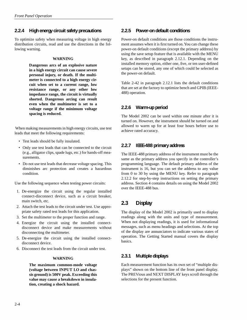
Front Panel Operation
2-4
2.2.4 High energy circuit safety precautions
To optimize safety when measuring voltage in high energydistribution circuits, read and use the directions in the fol-lowing warning.
WARNING
Dangerous arcs of an explosive naturein a high energy circuit can cause severepersonal injury, or death. If the multi-meter is connected to a high energy cir-cuit when set to a current range, lowresistance range, or any other lowimpedance range, the circuit is virtuallyshorted. Dangerous arcing can resulteven when the multimeter is set to avoltage range if the minimum voltagespacing is reduced.
When making measurements in high energy circuits, use testleads that meet the following requirements:
• Test leads should be fully insulated.
• Only use test leads that can be connected to the circuit(e.g., alligator clips, spade lugs, etc.) for hands-off mea-surements.
• Do not use test leads that decrease voltage spacing. Thisdiminishes arc protection and creates a hazardouscondition.
Use the following sequence when testing power circuits:
1. De-energize the circuit using the regular installedconnect-disconnect device, such as a circuit breaker,main switch, etc.
2. Attach the test leads to the circuit under test. Use appro-priate safety rated test leads for this application.
3. Set the multimeter to the proper function and range.
4. Energize the circuit using the installed connect-disconnect device and make measurements withoutdisconnecting the multimeter.
5. De-energize the circuit using the installed connect-disconnect device.
6. Disconnect the test leads from the circuit under test.
WARNING
The maximum common-mode voltage(voltage between INPUT LO and chas-sis ground) is 500V peak. Exceeding thisvalue may cause a breakdown in insula-tion, creating a shock hazard.
2.2.5 Power-on default conditions
Power-on default conditions are those conditions the instru-ment assumes when it is first turned on. You can change thesepower-on default conditions (except the primary address) byusing the save setup feature that is available with the MENUkey, as described in paragraph 2.12.1. Depending on theinstalled memory option, either one, five, or ten user-definedsetups can be stored, any one of which could be selected asthe power-on default.
Table 2-42 in paragraph 2.12.1 lists the default conditionsthat are set at the factory to optimize bench and GPIB (IEEE-488) operation.
2.2.6 Warm-up period
The Model 2002 can be used within one minute after it isturned on. However, the instrument should be turned on andallowed to warm up for at least four hours before use toachieve rated accuracy.
2.2.7 IEEE-488 primary address
The IEEE-488 primary address of the instrument must be thesame as the primary address you specify in the controller’sprogramming language. The default primary address of theinstrument is 16, but you can set the address to any valuefrom 0 to 30 by using the MENU key. Refer to paragraph2.12.2 for step-by-step instructions on setting the primaryaddress. Section 4 contains details on using the Model 2002over the IEEE-488 bus.
2.3 Display
The display of the Model 2002 is primarily used to displayreadings along with the units and type of measurement.When not displaying readings, it is used for informationalmessages, such as menu headings and selections. At the topof the display are annunciators to indicate various states ofoperation. The Getting Started manual covers the displaybasics.
2.3.1 Multiple displays
Each measurement function has its own set of “multiple dis-plays” shown on the bottom line of the front panel display.The PREVious and NEXT DISPLAY keys scroll through theselections for the present function.

Front Panel Operation
2-5
Some of the multiple displays are for multiple functions,where different functions are measured sequentially from thesame set of test leads. The readings are shown simulta-neously, such as:
• Top line shows a DC voltage measurement; bottom lineshows positive and negative peak spike measurements.
• Top line shows an AC RMS voltage reading; bottomline shows an AC frequency measurement and a crestfactor calculation.
Also, the multiple displays can show a reading in a differentform, or give additional information about the reading, forexample:
• Top line shows a reading; bottom line shows a zero-centered bar graph with adjustable limits.
• Top line shows a frequency measurement; bottom lineshows the adjustable trigger level.
To scroll through the multiple displays available for eachmeasurement function, repeatedly press and release theNEXT DISPLAY key. The same action with the PREViousDISPLAY key does a reverse scroll through the displays. Toreturn to the default reading display, just press and holdeither key.
Multiple displays that are specific to a particular function oroperation are discussed later in this section, such as the peakspikes displays in DC voltage, and the calculations display inmath. (See Table 2-3 for paragraph references.) Displays thatare common to most of the measurement functions are dis-cussed here.
Table 2-3Multiple displays by function
Function Next display Paragraph
All
DC voltage
AC voltage
DC currentAC current
2-wire resistance
4-wire resistance
Frequency
Temperature
Data storage buffer
Bar graph Zero-centered bar graph Maximum and minimum values Relative and actual values Calculated and actual values (see Note 1) Limits bar graph (see Note 1) Adjacent channel readings (see Note 2)DC volts, AC ripple voltage and frequency Positive peak spikes and highest valueNegative peak spikes and lowest valuePositive and negative peak spikesAC RMS voltage, frequency, and crest factor AC RMS, average, and peak voltages(none specific to function) AC RMS (or average) current and frequency AC RMS and average currentSource current Voltage drop across DUTSource current Voltage drop across DUTLead resistancePeriod calculation Trigger levelCelsius, Fahrenheit, and Kelvin units RTD resistance (or thermocouple voltage)Reference junction (thermocouples only)Maximum and minimum valuesAverage and standard deviation
2.3.12.3.12.3.12.62.102.12.52.112.4.1
2.4.1
2.4.22.4.2
2.4.3
2.4.3
2.4.4
2.4.5
2.8
Notes:1. Multiple displays for calculated values and limits bar graph are not available for the frequency function. 2. The multiple display for adjacent channel readings is not available for the DC and AC current functions.
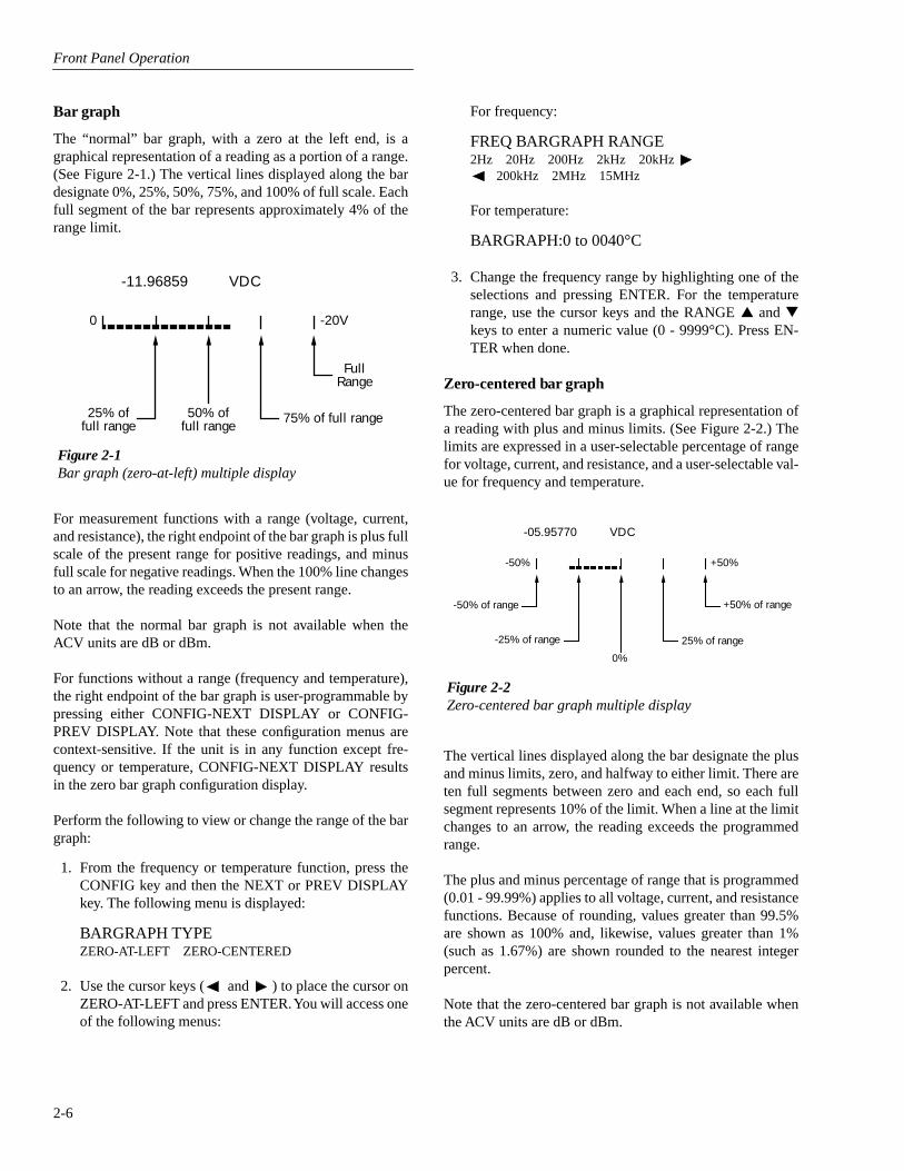
Front Panel Operation
2-6
Bar graph
The “normal” bar graph, with a zero at the left end, is agraphical representation of a reading as a portion of a range.(See Figure 2-1.) The vertical lines displayed along the bardesignate 0%, 25%, 50%, 75%, and 100% of full scale. Eachfull segment of the bar represents approximately 4% of therange limit.
For measurement functions with a range (voltage, current,and resistance), the right endpoint of the bar graph is plus fullscale of the present range for positive readings, and minusfull scale for negative readings. When the 100% line changesto an arrow, the reading exceeds the present range.
Note that the normal bar graph is not available when theACV units are dB or dBm.
For functions without a range (frequency and temperature),the right endpoint of the bar graph is user-programmable bypressing either CONFIG-NEXT DISPLAY or CONFIG-PREV DISPLAY. Note that these configuration menus arecontext-sensitive. If the unit is in any function except fre-quency or temperature, CONFIG-NEXT DISPLAY resultsin the zero bar graph configuration display.
Perform the following to view or change the range of the bargraph:
1. From the frequency or temperature function, press theCONFIG key and then the NEXT or PREV DISPLAYkey. The following menu is displayed:
BARGRAPH TYPE
ZERO-AT-LEFT ZERO-CENTERED
2. Use the cursor keys ( and ) to place the cursor onZERO-AT-LEFT and press ENTER. You will access oneof the following menus:
Figure 2-1Bar graph (zero-at-left) multiple display
25% offull range
FullRange
-11.96859 VDC
50% offull range
75% of full range
0 -20V
For frequency:
FREQ BARGRAPH RANGE
2Hz 20Hz 200Hz 2kHz 20kHz 200kHz 2MHz 15MHz
For temperature:
BARGRAPH:0 to 0040°C
3. Change the frequency range by highlighting one of theselections and pressing ENTER. For the temperaturerange, use the cursor keys and the RANGE
and
keys to enter a numeric value (0 - 9999°C). Press EN-TER when done.
Zero-centered bar graph
The zero-centered bar graph is a graphical representation ofa reading with plus and minus limits. (See Figure 2-2.) Thelimits are expressed in a user-selectable percentage of rangefor voltage, current, and resistance, and a user-selectable val-ue for frequency and temperature.
The vertical lines displayed along the bar designate the plusand minus limits, zero, and halfway to either limit. There areten full segments between zero and each end, so each fullsegment represents 10% of the limit. When a line at the limitchanges to an arrow, the reading exceeds the programmedrange.
The plus and minus percentage of range that is programmed(0.01 - 99.99%) applies to all voltage, current, and resistancefunctions. Because of rounding, values greater than 99.5%are shown as 100% and, likewise, values greater than 1%(such as 1.67%) are shown rounded to the nearest integerpercent.
Note that the zero-centered bar graph is not available whenthe ACV units are dB or dBm.
Figure 2-2Zero-centered bar graph multiple display
-50% of range
-25% of range
+50% of range
-05.95770 VDC
0%
25% of range
-50% +50%

Front Panel Operation
2-7
Perform the following to view or change the plus and minuspercentage of range:
1. From a voltage, current, or resistance function, pressCONFIG and then NEXT or PREV DISPLAY. The fol-lowing is displayed:
ZERO-BARGRAPH±50.00%
2. Change the percentage by using the cursor keys and theRANGE
and
keys to enter a numeric value (0.01 -99.99%). Press ENTER when done. The same percent-age of range is used for voltage, current, and resistancemeasurements.
Perform the following to view or change the plus and minusvalue limit:
1. From the frequency or temperature function, pressCONFIG and then NEXT or PREV DISPLAY. The fol-lowing menu is displayed:
BARGRAPH TYPE
ZERO-AT-LEFT ZERO-CENTERED
2. Use the cursor keys ( and ) to place the cursor onZERO-CENTERED and press ENTER. You will accessone of the following menus:
For frequency:
FREQ ZEROBARGRAPH(±)
1Hz 10Hz 100Hz 1kHz 10kHz 100kHz 1MHz 10MHz 15MHz
For temperature:
ZERO-BARGRAPH±0002°C
3. Change the frequency limits by highlighting one of theselections and pressing ENTER. For the temperature,use the cursor keys and the RANGE
and
keys toenter a numeric value (0 - 9999°C). Press ENTER whendone.
Maximum and minimum
The maximum and minimum multiple display shows themaximum and minimum readings since the display was en-tered. (See Figure 2-3.) The maximum and minimum valuesare reset by the following:
• Pressing the present function key.
• Leaving the display by changing function or entering amenu.
The resolution, units, and prefix on the bottom line are thesame as shown for top line reading. If necessary, the bottomline values automatically change to scientific notation,rounded to 4.5 digits.
2.3.2 Information messages
Press the INFO key to view context-sensitive informationfrom most of the displays. An arrow ( or ) on the bot-tom line indicates that there is more information. Use thecursor keys ( and ) to view the complete line. To exitan INFO display, just press INFO, ENTER, EXIT, or a func-tion key.
2.3.3 Status and error messages
During Model 2002 operation and programming, you willencounter a number of front panel messages. Typicalmessages are either of status or error variety, as listed inTable 2-4.
The most recent status or error messages can be momentarilydisplayed. Just enter a configuration menu or the main menu,and press the PREV key. (The display is blank if no messageis queued.)
Figure 2-3Maximum and minimum multiple display
Minimumvalue
-15.82867 VDC
Max = -05.74602 Min = -15.82867
Maximumvalue

Front Panel Operation
2-8
Table 2-4
Status and error messages
Number Description Event
+900 “Internal System Error” EE
+611+610
“Questionable Temperature” “Questionable Calibration”
SESE
+519+518+517+516+515+514+513+512+511+510
“Excessive temp drift during cal”“Low level calibration data lost”“Preamp calibration data lost”“Install option id lost”“Calibration dates lost” “DC calibration data lost” “AC calibration data lost” “Power-on state lost” “GPIB address lost”“Reading buffer data lost”
EEEEEEEEEEEEEEEEEEEE
+444 to+350
Calibration Errors(see Calibration Manual)
EE
+312+311+310+309+308+307+306+305+304+303+302+301
“Buffer pretriggered” “Buffer lost”“Buffer full” “Buffer half full” “Buffer Available” “Voltmeter complete”“Reading Available” “High limit 2 event” “Low limit 2 event” “High limit 1 event” “Low limit 1 event” “Reading overflow”
SESESESESESESESESESESESE
+174+173+172+171
“Re-entering the idle layer” “Waiting in arm layer 2” “Waiting in arm layer 1” “Waiting in trigger layer”
SESESESE
+161 “Program running” SE
+126+125+124+123+122+121
“Device calculating” “Device measuring”“Device sweeping”“Device ranging”“Device settling”“Device calibrating”
SESESESESESE
+101 “Operation complete” SE
+000 “No error” SE
-100-101-102-103-104-105-108-109
“Command error” “Invalid character”“Syntax error”“Invalid separator”“Data type error”“GET not allowed”“Parameter not allowed”“Missing parameter”
EEEEEEEEEEEEEEEE
-110-111-112
“Command header error”“Header separator error”“Program mnemonic too long”
EEEEEE
-113-114
“Undefined header” “Header suffix out of range”
EEEE
-120-121-123-124-128
“Numeric data error” “Invalid character in number”“Exponent too large” “Too many digits” “Numeric data not allowed”
EEEEEEEEEE
-140-141-144-148
“Character data error”“Invalid character data”“Character data too long”“Character data not allowed”
EEEEEEEE
-150-151-154-158
“String data error” “Invalid string data”“String too long”“String data not allowed”
EEEEEEEE
-160-161-168
“Block data error”“Invalid block data”“Block data not allowed”
EEEEEE
-170-171-178
“Expression error”“Invalid expression”“Expression data not allowed”
EEEEEE
-200-201-202
“Execution error”“Invalid while in local”“Settings lost due to rtl”(return to local)
EEEEEE
-210-211-212-213-214-215
“Trigger error” “Trigger ignored”“Arm ignored”“Init ignored”“Trigger deadlock”“Arm deadlock”
EEEEEEEEEEEE
-220-221-222-223-224
“Parameter Error” “Settings conflict”“Parameter data out of range”“Too much data”“Illegal parameter value”
EEEEEEEEEE
-230-241-260-281-282
“Data corrupt or stale”“Hardware missing”“Expression Error”“Cannot create program”“Illegal program name”
EEEEEEEEEE
-314-315-330-350
“Save/recall memory lost”“Configuration memory lost”“Self Test failed”“Queue overflow”
EEEEEEEE
-410-420-430-440
“Query interrupted”“Query unterminated”“Query deadlocked”“Query unterminated after indefi-
nite response”
EEEEEEEE
SE = Status eventEE = Error event
Table 2-4
Status and error messages (cont.)
Number Description Event

Front Panel Operation
2-9
2.3.4 Navigating menus
There are basically two types of menu structures; the MainMenu and the Configure menus. The Main Menu accessesitems for which there are no dedicated keys, and Configuremenus are used to configure measurement functions and oth-er instrument operations.
Use the following rules to navigate through the menu struc-ture:
1. The top level of the Main Menu is accessed by pressingthe MENU key. A Configuration menu is accessed bypressing CONFIG and then the desired function (DCV,ACV, etc.) or operation (TRIG, STORE, etc.).
2. A menu item is selected by placing the cursor on it andpressing ENTER. Cursor position is denoted by theblinking menu item or parameter. The cursor keys (and ) control cursor position.
3. A displayed arrow ( and ) on the bottom line indi-cates that there are one or more additional items (mes-sages) to select from. Use the appropriate cursor key todisplay them.
4. A numeric parameter is keyed in by placing the cursoron the digit to be changed and using the RANGE
or
key to increment or decrement the digit.
5. A change is only executed when ENTER is pressed.Entering an invalid parameter generates an error and theentry is ignored.
6. The EXIT key is used to back out of the menu structure.Any change that is not entered is cancelled when EXITis pressed. The EXIT key has additional actions and aresummarized in Table 2-5.
2.4 Functions
To minimize the need to reprogram setup conditions everytime you switch from one function to another, each function
“remembers” its own unique setup configuration. Setup con-figuration parameters that are remembered include:
• Range
• Relative
• Integration time
• Filtering
• Display resolution
• Multiple displays
To access the configuration menus for the measurementfunctions, press the CONFIG key and then a function key(DCV, ACV, DCI, ACI,
Ω
2,
Ω
4, FREQ, TEMP). Rules fornavigating the menu structures are covered in paragraph2.3.4.
2.4.1 DC and AC voltage
The Model 2002 can make DCV measurements from 1nV to1100V and ACV measurements from 10nV to 775V. Thebasic measurement procedures for DCV and ACV are con-tained in the Getting Started manual.
Voltage configuration
The following information explains the various configura-tion options for DC and AC voltage measurements. The con-figuration menus are summarized in Tables 2-6 and 2-7. Themenus are accessed by pressing CONFIG and then DCV orACV. Paragraph 2.3.5 summarizes the rules for navigatingthrough menus.
Note that a function does not have to be selected in order tobe configured. When the function is selected, it will assumethe programmed status.
Table 2-5EXIT key actions
Condition EXIT key action
Temporary message displayed (e.g., TRIGGERS HALTED)INFO message displayedReading display holdScanningData storage
Cancels display of temporary message.
Cancels INFO message, returns to menu or normal reading display.Cancels reading display hold, resumes normal reading display.Disables scanning. Also stops data storage if enabled.Stops data storage. Temporary message STORAGE INTERRUPTED is displayed.
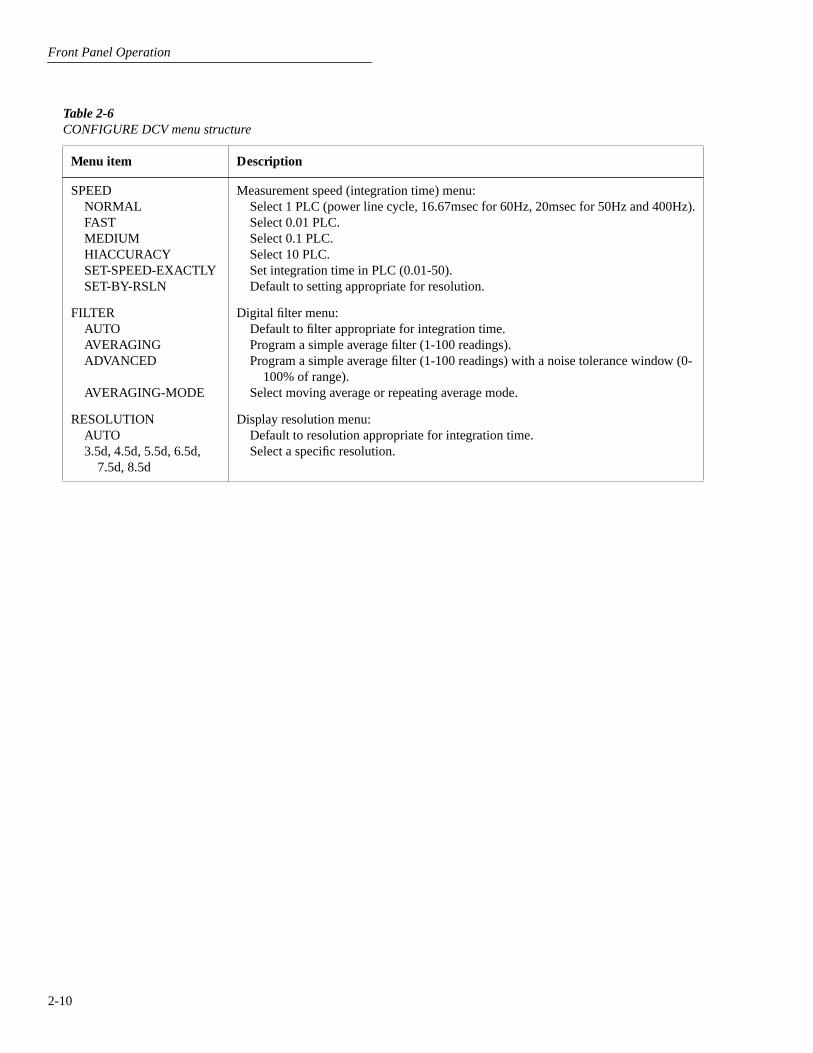
Front Panel Operation
2-10
Table 2-6
CONFIGURE DCV menu structure
Menu item Description
SPEEDNORMALFASTMEDIUMHIACCURACYSET-SPEED-EXACTLYSET-BY-RSLN
Measurement speed (integration time) menu:Select 1 PLC (power line cycle, 16.67msec for 60Hz, 20msec for 50Hz and 400Hz).Select 0.01 PLC.Select 0.1 PLC.Select 10 PLC.Set integration time in PLC (0.01-50).Default to setting appropriate for resolution.
FILTERAUTOAVERAGINGADVANCED
AVERAGING-MODE
Digital filter menu:Default to filter appropriate for integration time.Program a simple average filter (1-100 readings).Program a simple average filter (1-100 readings) with a noise tolerance window (0-
100% of range).Select moving average or repeating average mode.
RESOLUTIONAUTO3.5d, 4.5d, 5.5d, 6.5d,
7.5d, 8.5d
Display resolution menu:Default to resolution appropriate for integration time.Select a specific resolution.
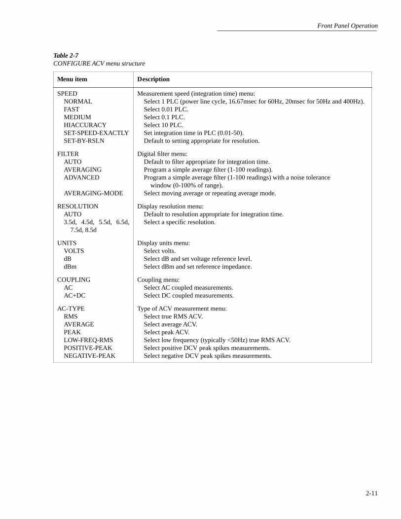
Front Panel Operation
2-11
Table 2-7
CONFIGURE ACV menu structure
Menu item Description
SPEEDNORMALFASTMEDIUMHIACCURACYSET-SPEED-EXACTLYSET-BY-RSLN
Measurement speed (integration time) menu:Select 1 PLC (power line cycle, 16.67msec for 60Hz, 20msec for 50Hz and 400Hz).Select 0.01 PLC.Select 0.1 PLC.Select 10 PLC.Set integration time in PLC (0.01-50).Default to setting appropriate for resolution.
FILTERAUTOAVERAGINGADVANCED
AVERAGING-MODE
Digital filter menu:Default to filter appropriate for integration time.Program a simple average filter (1-100 readings).Program a simple average filter (1-100 readings) with a noise tolerance
window (0-100% of range).Select moving average or repeating average mode.
RESOLUTIONAUTO3.5d, 4.5d, 5.5d, 6.5d,
7.5d, 8.5d
Display resolution menu:Default to resolution appropriate for integration time.Select a specific resolution.
UNITSVOLTSdBdBm
Display units menu:Select volts.Select dB and set voltage reference level.Select dBm and set reference impedance.
COUPLINGACAC+DC
Coupling menu:Select AC coupled measurements.Select DC coupled measurements.
AC-TYPERMSAVERAGEPEAKLOW-FREQ-RMS POSITIVE-PEAKNEGATIVE-PEAK
Type of ACV measurement menu:Select true RMS ACV.Select average ACV.Select peak ACV.Select low frequency (typically <50Hz) true RMS ACV.Select positive DCV peak spikes measurements.Select negative DCV peak spikes measurements.

Front Panel Operation
2-12
SPEED
The SPEED parameter sets the integration time of the A/Dconverter, the period of time the input signal is measured(also known as aperture). The integration time affects theusable resolution, the amount of reading noise, as well as theultimate reading rate of the instrument. From the front panel,the integration time is specified in parameters based on anumber of power line cycles (NPLC), where 1 PLC for 60Hzis 16.67msec and 1 PLC for 50Hz and 400Hz is 20msec.
The SPEED parameters for all functions (except frequency)are explained as follows:
FAST:
Sets integration time to 0.01 PLC. Use FAST if speedis of primary importance at the expense of increased readingnoise and less usable resolution.
MEDIUM:
Sets integration time to 0.1PLC. Use MEDIUMwhen a compromise between noise performance and speed isacceptable.
NORMAL:
Sets integration time to 1 PLC. A compromiselike MEDIUM, but NORMAL provides better noise perfor-mance at the expense of speed.
HIACCURACY:
Sets integration time to 10 PLC. UseHI-ACCURACY when high common-mode and normal-mode rejection is required.
SET-SPEED-EXACTLY:
When this parameter is selected,the current PLC value is displayed. By using the cursor keys( and ) and the RANGE
and
keys, you can enterany PLC value from 0.01 to 50. Be sure to press ENTERafter keying in a new value. Note that an integer PLC valuewill increase noise rejection.
SET-BY-RSLN:
This parameter optimizes the integrationtime for the present resolution setting. See Table 2-8 for thedefault integration times of the DCV and ACV functions.The default set-by-resolution integration times of other func-tions are listed in Tables 2-13, 2-18 and 2-24.
FILTER
FILTER lets you set the digital filter response. The filtermenu is available from the function configuration menus (i.e.CONFIGURE DCV) or by pressing CONFIGURE FILTERwith the desired function already selected. All of the param-eters (menu items) for FILTER are explained in paragraph2.9. Since the AUTO parameter has specific effects on DCVand ACV, it is covered here.
AUTO:
This parameter for a digital filter optimizes its usefor the present measurement function. The defaults for auto-matic filtering of DCV and ACV are listed in Table 2-9.
Table 2-8DCV and ACV integration times set-by-resolution
Measurement function and type Resolution
Integration time
DCV 3.5d, 4.5d 5.5d 6.5d 7.5d 8.5d
0.01 PLC0.02 PLC0.10 PLC1.00 PLC10.00 PLC
DCV peak spikes 3.5d (to 7.5d) Not used
RMS, average 3.5d, 4.5d 5.5d 6.5d, 7.5d, 8.5d
0.01 PLC0.02 PLC10.00 PLC
Low frequency RMS 3.5d to 8.5d Not used
ACV peak 4d (to 8d) Not used
Notes:1. For DCV measurements, if the integration time is SET-BY-RSLN
and the resolution AUTO, the integration time will be 1.0 PLC and the resolution 7.5 digits.
2. For RMS and average measurements, if the integration time is SET-BY-RSLN and the resolution is AUTO, the integration will be 1.0 PLC and the resolution 5.5 digits.
3. For DCV peak spikes, low frequency RMS, and ACV peak measure-ments, the integration time setting is ignored.
4. The resolution of DCV peak spikes can be from 3.5d to 8.5d, but the accuracy is specified at 3.5d. The resolution of ACV peak can be from 4d to 8d, but the accuracy is specified at 4d.

Front Panel Operation
2-13
RESOLUTION
Except for frequency, temperature, and some special cases ofAC voltage, all functions can operate with 3½ to 8½-digitresolution, or they can default to a setting appropriate for theselected integration time.
3.5d, 4.5d, 5.5d, 6.5d, 7.5d or 8.5d: Sets resolution to thespecified number of digits.
AUTO: optimizes the resolution for the present integrationtime setting. See Table 2-10 for the default resolutions of theDCV and ACV functions. The default resolutions of theother functions are listed in Tables 2-15, 2-20 and 2-25.
UNITS
This parameter selects the displayed units for AC voltagemeasurements.
VOLTS: With volts selected as the units, AC voltage mea-surements are expressed in volts.
dB: Expressing AC voltage in dB makes it possible to com-press a large range of measurements into a much smallerscope. The relationship between dB and voltage is defined bythe following equation:
where: VIN is the AC input signal.
VREF is the specified voltage reference level.
Table 2-9DCV and ACV auto filter
Measurement function and type Units State Type Readings
Noise tolerance
AveragingMode
DCV - On Advanced 10 1.0% Moving
DCV peak spikes - On Advanced 10 5.0% Moving
RMS, average, low fre-quency RMS
Any Off Advanced 10 5.0% Moving
ACV peak VoltsdB, dBm
OnOn
AdvancedAveraging
1010
5.0%–
MovingMoving
dB = 20 logV
IN
V
REF -------------
The instrument will read 0dB when the reference voltagelevel is applied to the input. dB measurements are possibleon all ACV measurement types except positive peak spikesand negative peak spikes, as these may be negative, and thelog of a negative number is not defined. Note that dB mea-
Table 2-10
DCV and ACV auto resolution
Measurement function and type Integration time Resolution
DCV 0.01 to <0.02 PLC 0.02 to <0.10 PLC 0.10 to <1.00 PLC 1.00 to <10.00 PLC 10.00 to 50 PLC
4.5d5.5d6.5d7.5d8.5d
DCV peak spikes Not used 3.5d
RMS, average 0.01 to <0.02 PLC 0.02 to <10.00 PLC 10.00 to 50 PLC
4.5d5.5d6.5d
Low frequency RMS Not used 5.5d
ACV peak Not used 4d
Notes:1. If the DCV resolution is AUTO and the integration time SET-BY-
RSLN, the resolution will be 7.5 digits and the integration time 1.0 PLC.
2. For DCV peak spikes, low frequency RMS, and ACV peak measure-ments, the integration time setting is ignored.
3. For RMS and average measurements, if the resolution is AUTO and the integration time is SET-BY-RSLN, the resolution will be 5.5 digits and the integration time 1.0 PLC.
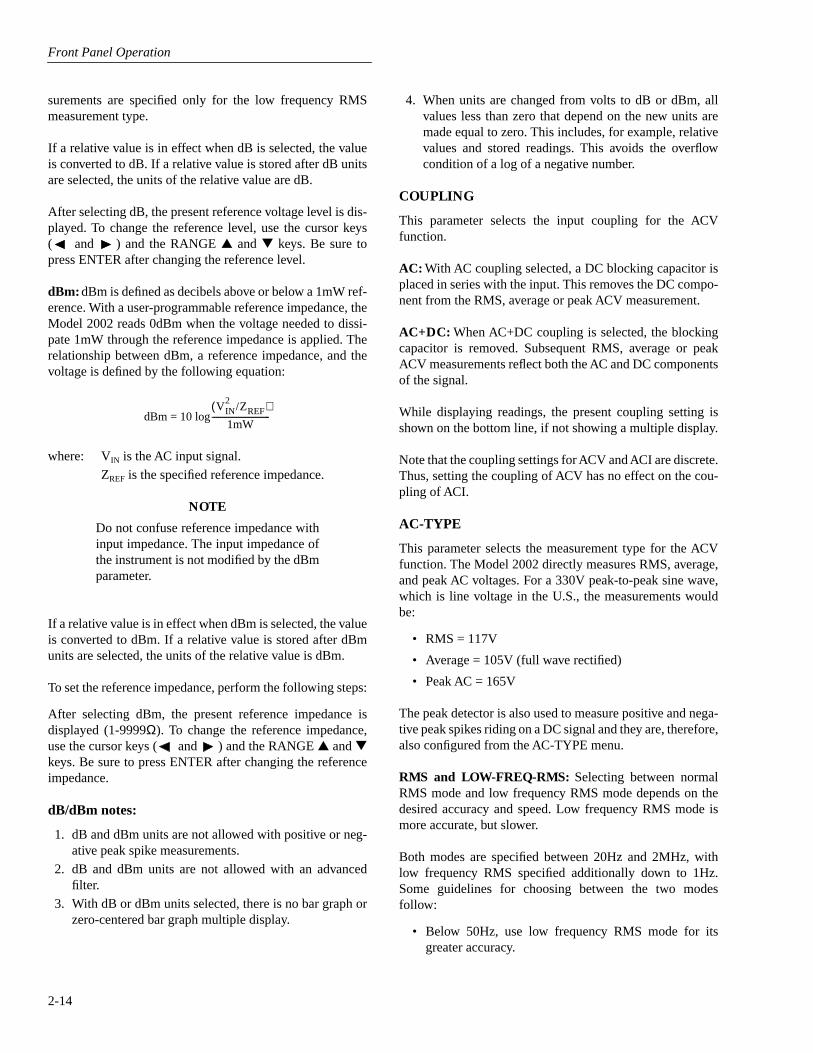
Front Panel Operation
2-14
surements are specified only for the low frequency RMSmeasurement type.
If a relative value is in effect when dB is selected, the valueis converted to dB. If a relative value is stored after dB unitsare selected, the units of the relative value are dB.
After selecting dB, the present reference voltage level is dis-played. To change the reference level, use the cursor keys( and ) and the RANGE
and
keys. Be sure topress ENTER after changing the reference level.
dBm:
dBm is defined as decibels above or below a 1mW ref-erence. With a user-programmable reference impedance, theModel 2002 reads 0dBm when the voltage needed to dissi-pate 1mW through the reference impedance is applied. Therelationship between dBm, a reference impedance, and thevoltage is defined by the following equation:
where: V
IN
is the AC input signal.
Z
REF
is the specified reference impedance.
NOTE
Do not confuse reference impedance withinput impedance. The input impedance ofthe instrument is not modified by the dBmparameter.
If a relative value is in effect when dBm is selected, the valueis converted to dBm. If a relative value is stored after dBmunits are selected, the units of the relative value is dBm.
To set the reference impedance, perform the following steps:
After selecting dBm, the present reference impedance isdisplayed (1-9999
Ω
). To change the reference impedance,use the cursor keys ( and ) and the RANGE
and
keys. Be sure to press ENTER after changing the referenceimpedance.
dB/dBm notes:
1. dB and dBm units are not allowed with positive or neg-ative peak spike measurements.
2. dB and dBm units are not allowed with an advancedfilter.
3. With dB or dBm units selected, there is no bar graph orzero-centered bar graph multiple display.
4. When units are changed from volts to dB or dBm, allvalues less than zero that depend on the new units aremade equal to zero. This includes, for example, relativevalues and stored readings. This avoids the overflowcondition of a log of a negative number.
COUPLING
This parameter selects the input coupling for the ACVfunction.
AC:
With AC coupling selected, a DC blocking capacitor isplaced in series with the input. This removes the DC compo-nent from the RMS, average or peak ACV measurement.
AC+DC:
When AC+DC coupling is selected, the blockingcapacitor is removed. Subsequent RMS, average or peakACV measurements reflect both the AC and DC componentsof the signal.
While displaying readings, the present coupling setting isshown on the bottom line, if not showing a multiple display.
Note that the coupling settings for ACV and ACI are discrete.Thus, setting the coupling of ACV has no effect on the cou-pling of ACI.
AC-TYPE
This parameter selects the measurement type for the ACVfunction. The Model 2002 directly measures RMS, average,and peak AC voltages. For a 330V peak-to-peak sine wave,which is line voltage in the U.S., the measurements wouldbe:
• RMS = 117V
• Average = 105V (full wave rectified)
• Peak AC = 165V
The peak detector is also used to measure positive and nega-tive peak spikes riding on a DC signal and they are, therefore,also configured from the AC-TYPE menu.
RMS and LOW-FREQ-RMS:
Selecting between normalRMS mode and low frequency RMS mode depends on thedesired accuracy and speed. Low frequency RMS mode ismore accurate, but slower.
Both modes are specified between 20Hz and 2MHz, withlow frequency RMS specified additionally down to 1Hz.Some guidelines for choosing between the two modesfollow:
• Below 50Hz, use low frequency RMS mode for itsgreater accuracy.
dBm = 10 logV
IN2
/Z
REF
( )
1mW-----------------------------
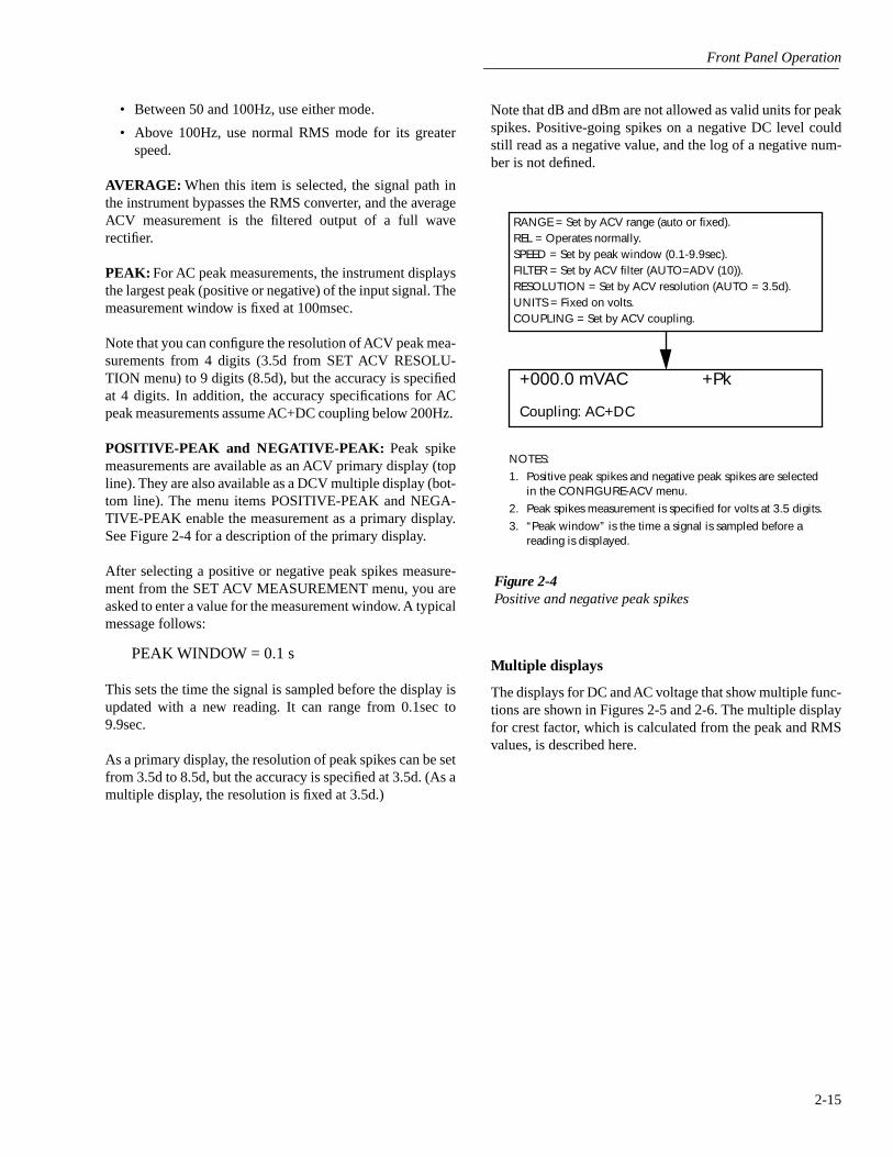
Front Panel Operation
2-15
• Between 50 and 100Hz, use either mode.
• Above 100Hz, use normal RMS mode for its greaterspeed.
AVERAGE:
When this item is selected, the signal path inthe instrument bypasses the RMS converter, and the averageACV measurement is the filtered output of a full waverectifier.
PEAK:
For AC peak measurements, the instrument displaysthe largest peak (positive or negative) of the input signal. Themeasurement window is fixed at 100msec.
Note that you can configure the resolution of ACV peak mea-surements from 4 digits (3.5d from SET ACV RESOLU-TION menu) to 9 digits (8.5d), but the accuracy is specifiedat 4 digits. In addition, the accuracy specifications for ACpeak measurements assume AC+DC coupling below 200Hz.
POSITIVE-PEAK and NEGATIVE-PEAK:
Peak spike
measurements are available as an ACV primary display (topline). They are also available as a DCV multiple display (bot-tom line). The menu items POSITIVE-PEAK and NEGA-TIVE-PEAK enable the measurement as a primary display.See Figure 2-4 for a description of the primary display.
After selecting a positive or negative peak spikes measure-ment from the SET ACV MEASUREMENT menu, you areasked to enter a value for the measurement window. A typicalmessage follows:
PEAK WINDOW = 0.1 s
This sets the time the signal is sampled before the display isupdated with a new reading. It can range from 0.1sec to9.9sec.
As a primary display, the resolution of peak spikes can be setfrom 3.5d to 8.5d, but the accuracy is specified at 3.5d. (As amultiple display, the resolution is fixed at 3.5d.)
Note that dB and dBm are not allowed as valid units for peakspikes. Positive-going spikes on a negative DC level couldstill read as a negative value, and the log of a negative num-ber is not defined.
Multiple displays
The displays for DC and AC voltage that show multiple func-tions are shown in Figures 2-5 and 2-6. The multiple displayfor crest factor, which is calculated from the peak and RMSvalues, is described here.
Figure 2-4Positive and negative peak spikes
RANGE = Set by ACV range (auto or fixed).REL = Operates normally.SPEED = Set by peak window (0.1-9.9sec).FILTER = Set by ACV filter (AUTO=ADV (10)).RESOLUTION = Set by ACV resolution (AUTO = 3.5d).UNITS = Fixed on volts.COUPLING = Set by ACV coupling.
+000.0 mVAC +Pk
Coupling: AC+DC
NOTES:
1. Positive peak spikes and negative peak spikes are selected in the CONFIGURE-ACV menu.
2. Peak spikes measurement is specified for volts at 3.5 digits.
3. “Peak window” is the time a signal is sampled before a reading is displayed.

Front Panel Operation
2-16
Figure 2-5
DC voltage multifunction multiple displays
DCV
RANGE = Set by DCV range (auto or fixed).Autoranges independently of other functions.
REL = Operates normally.SPEED = Set by DCV speed.FILTER = Set by DCV filter.RESOLUTION = Set by DCV resolution.
ACV
RANGE = Set by ACV range (auto or fixed).Autoranges independently of other functions.
REL = No effect.SPEED = Set by ACV speed.FILTER = Unaffected by DCV and ACV filters.RESOLUTION = Set by ACV resolution.UNITS = Fixed on volts.COUPLING = Fixed on AC coupling.AC-TYPE = Fixed on normal mode RMS.
+000.0000 mVDC
+000.000 mVAC +000.00 Hz
FREQ
RANGE = Set by MAX-SIGNAL-LEVEL in CONFIGUREFREQUENCY menu.Autorange has no effect.
REL = No effect.TRIGGER LEVEL = Set while in FREQ. Not available in
CONFIGURE FREQUENCY menu.FILTER = Unaffected by DCV filter. FREQ has no filter.RESOLUTION = Fixed at 5 digits.COUPLING = Fixed on AC coupling.INPUT TERMINALS = Fixed on VOLTAGE.
A. DC voltage, AC voltage, and frequency functions

Front Panel Operation
2-17
Figure 2-5
DC voltage multifunction multiple displays (cont.)
DCV
RANGE = Set by DCV range (auto or fixed).Autoranges independently of other functions.
REL = Operates normally.SPEED = Set by DCV speed.FILTER = Set by DCV filter.RESOLUTION = Set by DCV resolution.
Pos-Pk
RANGE = Follows the DCV range.REL = No effect.SPEED = Fixed at 100msec.
Peak window has no effect.FILTER = Unaffected by DCV and ACV filters.RESOLUTION = Fixed at 3.5 digits.UNITS = Fixed on volts.COUPLING = Fixed on AC+DC coupling.
NOTE: The peak detector captures the maximum value of the input signal.
+000.0000 mVDC
Pos-Pk=+000.0mV Highest=+000.0mV
Highest
REL = No effect.RESOLUTION = Fixed at 3.5 digits.UNITS = Fixed on volts.
NOTE: The highest value is reset by pressing the DCV key, or changing function (i.e., leaving this display).
B. DC voltage and positive peak spikes functions
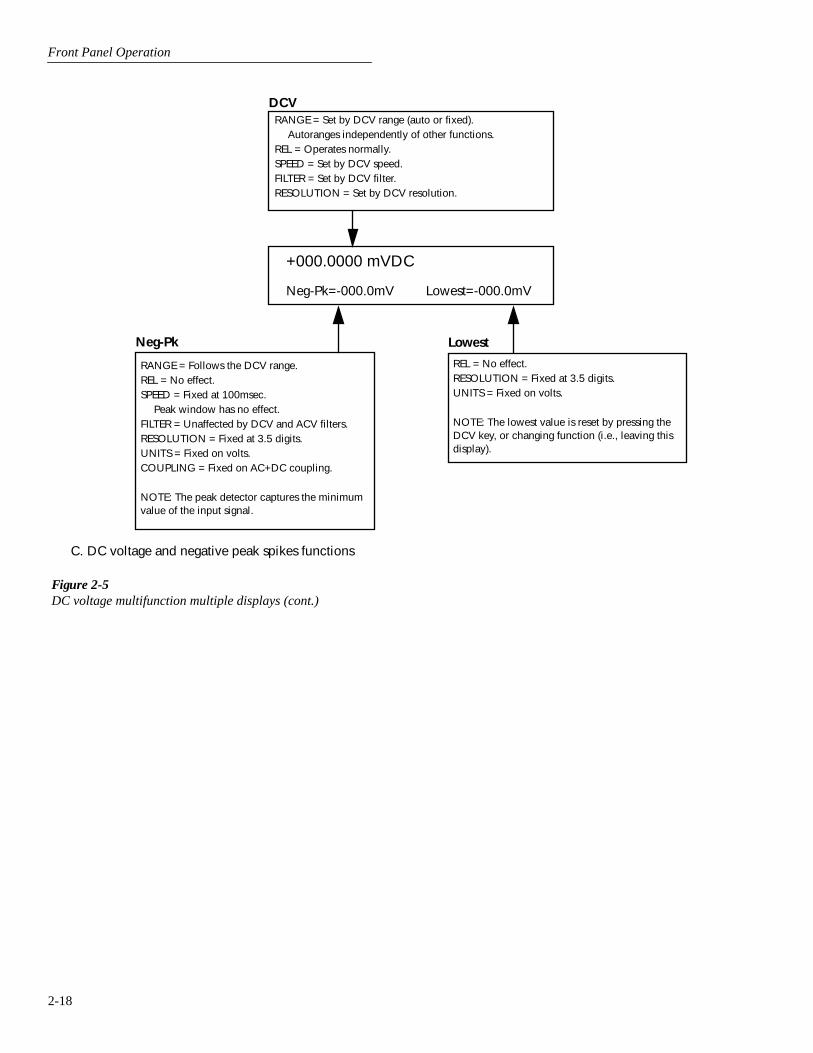
Front Panel Operation
2-18
Figure 2-5
DC voltage multifunction multiple displays (cont.)
DCV
RANGE = Set by DCV range (auto or fixed).Autoranges independently of other functions.
REL = Operates normally.SPEED = Set by DCV speed.FILTER = Set by DCV filter.RESOLUTION = Set by DCV resolution.
Neg-Pk
RANGE = Follows the DCV range.REL = No effect.SPEED = Fixed at 100msec.
Peak window has no effect.FILTER = Unaffected by DCV and ACV filters.RESOLUTION = Fixed at 3.5 digits.UNITS = Fixed on volts.COUPLING = Fixed on AC+DC coupling.
NOTE: The peak detector captures the minimum value of the input signal.
+000.0000 mVDC
Neg-Pk=-000.0mV Lowest=-000.0mV
Lowest
REL = No effect.RESOLUTION = Fixed at 3.5 digits.UNITS = Fixed on volts.
NOTE: The lowest value is reset by pressing the DCV key, or changing function (i.e., leaving this display).
C. DC voltage and negative peak spikes functions

Front Panel Operation
2-19
Figure 2-5
DC voltage multifunction multiple displays (cont.)
DCV
RANGE = Set by DCV range (auto or fixed).Autoranges independently of other functions.
REL = Operates normally.SPEED = Set by DCV speed.FILTER = Set by DCV filter.RESOLUTION = Set by DCV resolution.
Pos-Pk
RANGE = Follows the DCV range.REL = No effect.SPEED = Fixed at 100msec.
Peak window has no effect.FILTER = Unaffected by DCV and ACV filters.RESOLUTION = Fixed at 3.5 digits.UNITS = Fixed on volts.COUPLING = Fixed on AC+DC coupling.
NOTE: The peak detector captures the maximum value of the input signal.
+000.0000 mVDC
Pos-Pk=+000.0mV Neg-Pk=-000.0mV
D. DC voltage, positive and negative peak spikes functions
Neg-Pk
RANGE = Follows the DCV range.REL = No effect.SPEED = Fixed at 100msec.
Peak window has no effect.FILTER = Unaffected by DCV and ACV filters.RESOLUTION = Fixed at 3.5 digits.UNITS = Fixed on volts.COUPLING = Fixed on AC+DC coupling.
NOTE: The peak detector captures the minimum value of the input signal.

Front Panel Operation
2-20
Figure 2-6
AC voltage multifunction multiple displays
RMS
RANGE = Set by ACV range (auto or fixed).Autoranges independently of other functions.
REL = Operates normally.SPEED = Set by ACV speed.FILTER = Set by ACV filter.RESOLUTION = Set by ACV resolution.UNITS = Set by ACV units.COUPLING = Set by ACV coupling.AC-TYPE = Fixed on normal mode RMS.
FREQ
+000.000 mVAC RMS
+000.00Hz Crest Factor=0.00
Crest Factor
RANGE = ACV peak measurement range set by ACV range(auto or fixed). Peak measurement autoranges independentlyof other functions.
REL = No effect.SPEED = Fixed at 100msec. Peak window has no effect.FILTER = If ACV filter is on, crest factor is effectively filtered as
well.RESOLUTION = Fixed at 3 digits.UNITS = None.COUPLING = ACV peak measurement coupling set by ACV
coupling.
NOTE: Crest factor (up to 9.99) is calculated from an ACV peak measurement divided by the raw (without rel) ACV RMS measure-ment.
A. AC RMS voltage, frequency, and crest factor
RANGE = Set by MAX-SIGNAL-LEVEL in CONFIGURE FREQUENCY menu.Autorange has no effect.
REL = No effect.TRIGGER LEVEL= Set while in FREQ. Not available in
CONFIGURE FREQUENCY menu.FILTER = Unaffected by ACV filter. FREQ has no filter.RESOLUTION = Fixed at 5 digits.COUPLING = Set by ACV coupling.INPUT TERMINALS = Fixed on VOLTAGE.

Front Panel Operation
2-21
Figure 2-6
AC voltage multifunction multiple displays (cont.)
RMS
RANGE = Set by ACV range (auto or fixed).Autoranges independently of other functions.
REL = Operates normally.SPEED = Set by ACV speed.FILTER = Set by ACV filter.RESOLUTION = Set by ACV resolution.UNITS = Set by ACV units.COUPLING = Set by ACV coupling.AC-TYPE = Fixed on normal mode RMS.
AVG
RANGE = Set by ACV range (auto or fixed).Autoranges independently of other functions.
REL = No effect.SPEED= Set by ACV speed.FILTER = Unaffected by ACV filter.RESOLUTION = Fixed at 5.5 digits.UNITS = Fixed on volts.COUPLING = Set by ACV coupling.
+000.000 mVAC RMS
AVG=000.000mV Peak=000.0mV
Peak
RANGE = Set by ACV range (auto or fixed).
Autoranges independently of other functions.REL = No effect.SPEED = Fixed at 100msec. Peak window has no
effect.FILTER = Unaffected by ACV filter.RESOLUTION = Fixed at 4 digits.UNITS = Fixed on volts.COUPLING = Set by ACV coupling.
B. AC RMS, average, and peak voltages

Front Panel Operation
2-22
Crest factor —
The crest factor of a waveform is the ratio ofits peak value to its RMS value. Thus, the crest factor speci-fies the dynamic range of a true RMS instrument. For sinu-soidal waveforms, the crest factor is 1.414. For asymmetrical square wave, the crest factor is unity. The crestfactor of a rectangular pulse is related to its duty cycle; as theduty cycle decreases, the crest factor increases.
For the Model 2002, the additional error term for RMS mea-surements caused by a high crest factor is specified up to avalue of five. The maximum displayable value is 9.99, else itshows “over”.
Note that the crest factor is not calculated if dB or dBm is thepresently selected units.
Low level considerations
For sensitive measurements, external considerations besidesthe Model 2002 affect the accuracy. Effects not noticeablewhen working with higher voltages are significant in micro-volt signals. The Model 2002 reads only the signal receivedat its input; therefore, it is important that this signal be prop-erly transmitted from the source. The following paragraphsindicate factors that affect accuracy, including thermal off-sets and stray pick-up.
Shielding
—
AC voltages that are extremely large comparedwith the DC signal to be measured may produce an errone-ous output. Therefore, to minimize AC interference, the cir-cuit should be shielded with the shield connected to theModel 2002 INPUT LO (particularly for low-level sources).Improper shielding can cause the Model 2002 to behave inone or more of the following ways:
• Unexpected offset voltages.
• Inconsistent readings between ranges.
• Sudden shifts in reading.
To minimize pick-up, keep the voltage source and the Model2002 away from strong AC magnetic sources. The voltage in-duced due to magnetic flux is proportional to the area of theloop formed by the input leads. Therefore, minimize the looparea of the input leads and connect each signal at only onepoint.
Thermal EMFs
—
Thermal emfs (thermoelectric potentials)are generated by thermal differences between the junctionsof dissimilar metals. These can be large compared to the sig-nal that the Model 2002 can measure. Thermal emfs cancause the following conditions:
• Instability or zero offset is much higher than expected.
• The reading is sensitive to (and responds to)temperature changes. This effect can be demonstratedby touching the circuit, by placing a heat source nearthe circuit, or by a regular pattern of instability(corresponding to heating and air conditioning systems,or changes in sunlight).
To minimize the drift caused by thermal emfs, use copperleads to connect the circuit to the Model 2002. A banana pluggenerates a few microvolts. A clean copper conductor suchas #10 bus wire is ideal for this application. The leads to theinput may be shielded or unshielded, as necessary. Refer toShielding.
Widely varying temperatures within the circuit can also cre-ate thermal emfs. Therefore, maintain constant offset tem-peratures to minimize these thermal emfs. A cardboard boxaround the circuit under test also helps by minimizing aircurrents.
The REL control can be used to null out constant offsetvoltages.
Note that additional thermals may be generated by theoptional Model 2002-SCAN scanner card.
AC voltage offset
—
The Model 2002, at 5
½
d resolution,will typically display 150 counts of offset on AC volts withthe input shorted. This offset is caused by the offset of theTRMS converter. This offset will not affect reading accuracyand should not be zeroed out using the rel feature. The fol-lowing equation expresses how this offset (V
OFFSET
) is addedto the signal input (V
IN
):
Example: Range = 2VAC
Offset = 150 counts (1.5mV)
Input = 200mV RMS
The offset is seen as the last digit which is not displayed.Therefore, the offset is negligible. If the rel feature were usedto zero the display, the 150 counts of offset would be sub-tracted from V
IN
resulting in an error of 150 counts in the dis-played reading.
Displayed reading V IN ( ) 2
+ V OFFSET ( ) 2
=
Display reading 200mV ( ) 2 + 1.5mV ( )
2 =
= 0.04V 2.25 10-6
V×( )+
= .200005V

Front Panel Operation
2-23
2.4.2 DC and AC current
The Model 2002 can make normal DCI measurements from10pA and 2.1A and ACI measurements from 100pA to 2.1A.The basic measurement procedures for DCI and ACI are con-tained in the Getting Started manual.
AMPS fuse replacement
There are two protection fuses for the current ranges, one forthe front terminals, another for the rear. This proceduredescribes how to change an AMPS fuse.
WARNING
Make sure the instrument is disconnect-ed from the power line and other equip-ment before replacing an AMPS fuse.
1. Turn off the power and disconnect the power line andtest leads.
2. Perform one of the following steps:
A. For the front panel AMPS fuse, gently push in theAMPS jack with your thumb and rotate the fuse car-rier one-quarter turn counter-clockwise. Releasepressure on the jack and its internal spring will pushthe jack out of the socket.
B. For the rear panel AMPS fuse, place the end of aflat-blade screwdriver into the rear panel AMPSholder. Push in gently and rotate the fuse carrierone-quarter turn counter-clockwise. Release pres-sure on the holder and its internal spring will pushthe fuse carrier out of the holder.
3. Remove the fuse and replace it with the same type (2A,250V, fast blow, 5
×
20mm). The Keithley part numberis FU-48.
CAUTION
Do not use a fuse with a higher currentrating than specified, or instrumentdamage may occur. If the instrumentrepeatedly blows fuses, locate and cor-rect the cause of the trouble beforereplacing the fuse. See the optionalModel 2002 Repair Manual for trouble-shooting information.
4. Install the new fuse by reversing the above procedure.
Current configuration
The following information explains the various configura-tion options for DC and AC current measurements. The con-figuration menus are summarized in Tables 2-11 and 2-12.The menus are accessed by pressing CONFIG and then DCIor ACI. Paragraph 2.3.5 summarizes the rules for navigatingthrough the menus.
Note that a function does not have to be selected in order tobe configured. When the function is selected, it will assumethe programmed status.

Front Panel Operation
2-24
Table 2-11
CONFIGURE DCI menu structure
Menu item Description
SPEEDNORMALFASTMEDIUMHIACCURACYSET-SPEED-EXACTLYSET-BY-RSLN
Measurement speed (integration time) menu:Select 1 PLC (power line cycle, 16.67msec for 60Hz, 20msec for 50Hz and 400Hz).Select 0.01 PLC.Select 0.1 PLC.Select 10 PLC.Set integration time in PLC (0.01-50).Default to setting appropriate for resolution.
FILTERAUTOAVERAGINGADVANCED
AVERAGING-MODE
Digital filter menu:Default to filter appropriate for integration time.Program a simple average filter (1-100 readings).Program a simple average filter (1-100 readings) with a noise tolerance window (0-
100% of range).Select moving average or repeating average mode.
RESOLUTIONAUTO3.5d, 4.5d, 5.5d, 6.5d,
7.5d, 8.5d
Display resolution menu:Default to resolution appropriate for integration time.Select a specific resolution.
MEASUREMENT-MODENORMALIN-CIRCUIT
Measurement mode menu:Select normal current measurement (use AMPS terminals).Select in-circuit current measurement (use INPUT and SENSE terminals).
Table 2-12
CONFIGURE ACI menu structure
Menu item Description
SPEEDNORMAL
FASTMEDIUMHIACCURACYSET-SPEED-EXACTLYSET-BY-RSLN
Measurement speed (integration time) menu:Select 1 PLC (power line cycle, 16.67msec for 60Hz, 20msec for 50Hz and
400Hz).Select 0.01 PLC.Select 0.1 PLC.Select 10 PLC.Set integration time in PLC (0.01-50).Default to setting appropriate for resolution.
FILTERAUTOAVERAGINGADVANCED
AVERAGING-MODE
Digital filter menu:Default to filter appropriate for integration time.Program a simple average filter (1-100 readings).Program a simple average filter (1-100 readings) with a noise tolerance window
(0-100% of range).Select moving average or repeating average mode.
RESOLUTIONAUTO3.5d, 4.5d, 5.5d, 6.5d, 7.5d, 8.5d
Display resolution menu:Default to resolution appropriate for integration time.Select a specific resolution.
COUPLINGACAC+DC
Coupling menu:Select AC coupled measurements.Select DC coupled measurements.
AC-TYPERMSAVERAGE
Type of ACI measurement menu:Select true RMS ACI.Select average ACI.
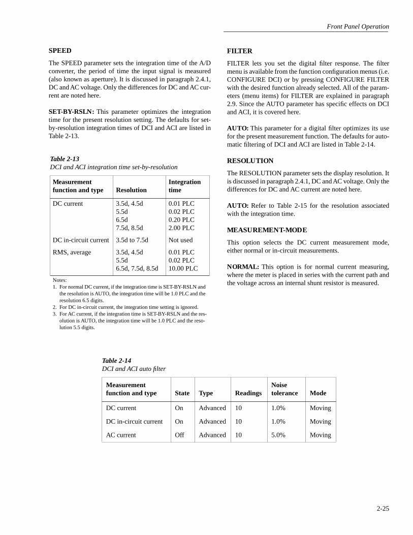
Front Panel Operation
2-25
SPEED
The SPEED parameter sets the integration time of the A/Dconverter, the period of time the input signal is measured(also known as aperture). It is discussed in paragraph 2.4.1,DC and AC voltage. Only the differences for DC and AC cur-rent are noted here.
SET-BY-RSLN:
This parameter optimizes the integrationtime for the present resolution setting. The defaults for set-by-resolution integration times of DCI and ACI are listed inTable 2-13.
Table 2-13
DCI and ACI integration time set-by-resolution
Measurement function and type Resolution
Integration time
DC current 3.5d, 4.5d 5.5d 6.5d 7.5d, 8.5d
0.01 PLC0.02 PLC0.20 PLC2.00 PLC
DC in-circuit current 3.5d to 7.5d Not used
RMS, average 3.5d, 4.5d 5.5d 6.5d, 7.5d, 8.5d
0.01 PLC0.02 PLC10.00 PLC
Notes:1. For normal DC current, if the integration time is SET-BY-RSLN and
the resolution is AUTO, the integration time will be 1.0 PLC and the resolution 6.5 digits.
2. For DC in-circuit current, the integration time setting is ignored. 3. For AC current, if the integration time is SET-BY-RSLN and the res-
olution is AUTO, the integration time will be 1.0 PLC and the reso-lution 5.5 digits.
Table 2-14
DCI and ACI auto filter
Measurement function and type State Type Readings
Noise tolerance Mode
DC current On Advanced 10 1.0% Moving
DC in-circuit current On Advanced 10 1.0% Moving
AC current Off Advanced 10 5.0% Moving
FILTER
FILTER lets you set the digital filter response. The filtermenu is available from the function configuration menus (i.e.CONFIGURE DCI) or by pressing CONFIGURE FILTERwith the desired function already selected. All of the param-eters (menu items) for FILTER are explained in paragraph2.9. Since the AUTO parameter has specific effects on DCIand ACI, it is covered here.
AUTO:
This parameter for a digital filter optimizes its usefor the present measurement function. The defaults for auto-matic filtering of DCI and ACI are listed in Table 2-14.
RESOLUTION
The RESOLUTION parameter sets the display resolution. Itis discussed in paragraph 2.4.1, DC and AC voltage. Only thedifferences for DC and AC current are noted here.
AUTO:
Refer to Table 2-15 for the resolution associatedwith the integration time.
MEASUREMENT-MODE
This option selects the DC current measurement mode,either normal or in-circuit measurements.
NORMAL:
This option is for normal current measuring,where the meter is placed in series with the current path andthe voltage across an internal shunt resistor is measured.
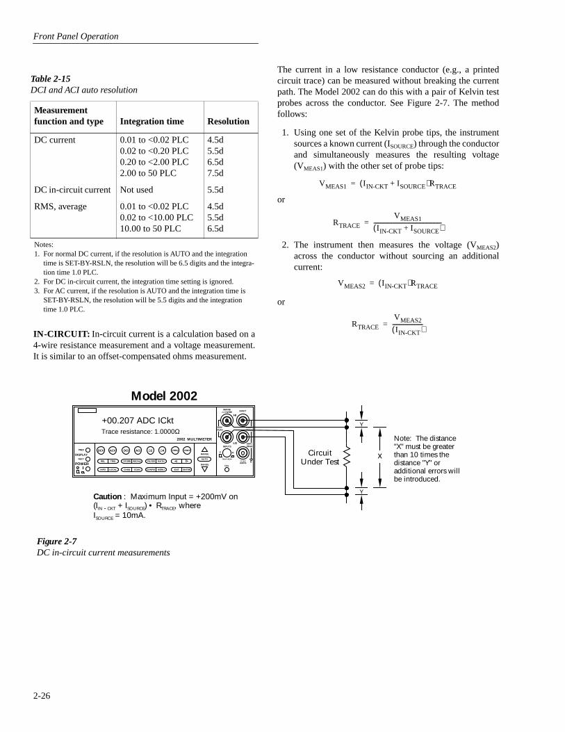
Front Panel Operation
2-26
IN-CIRCUIT:
In-circuit current is a calculation based on a4-wire resistance measurement and a voltage measurement.It is similar to an offset-compensated ohms measurement.
Table 2-15
DCI and ACI auto resolution
Measurement function and type Integration time Resolution
DC current 0.01 to <0.02 PLC 0.02 to <0.20 PLC 0.20 to <2.00 PLC 2.00 to 50 PLC
4.5d5.5d6.5d7.5d
DC in-circuit current Not used 5.5d
RMS, average 0.01 to <0.02 PLC0.02 to <10.00 PLC10.00 to 50 PLC
4.5d5.5d6.5d
Notes:1. For normal DC current, if the resolution is AUTO and the integration
time is SET-BY-RSLN, the resolution will be 6.5 digits and the integra-tion time 1.0 PLC.
2. For DC in-circuit current, the integration time setting is ignored. 3. For AC current, if the resolution is AUTO and the integration time is
SET-BY-RSLN, the resolution will be 5.5 digits and the integration time 1.0 PLC.
Figure 2-7DC in-circuit current measurements
NEXT
DISPLAY
PREV
POWER
DCV ACV DCI ACI Ω2 Ω4 FREQ TEMP
REL TRIG STORE RECALL
INFO LOCAL CHAN SCAN CONFIG MENU EXIT ENTER
RANGE
AUTOFILTER MATH
RANGE
2002 MULTIMETER
SENSE
Ω 4 WIRE
HI
INPUT
LOINPUTS
CAL
500V
PEAK
F R
FRONT/REAR
2A 250V
AMPS
350V
PEAK1100V
PEAK
Model 2002
CircuitUnder Test
Caution : Maximum Input = +200mV on(IIN - CKT + ISOURCE) • RTRACE, whereISOURCE = 10mA.
+00.207 ADC ICktTrace resistance: 1.0000Ω
Y
Y
x
Note: The distance"X" must be greaterthan 10 times thedistance "Y" oradditional errors willbe introduced.
The current in a low resistance conductor (e.g., a printedcircuit trace) can be measured without breaking the currentpath. The Model 2002 can do this with a pair of Kelvin testprobes across the conductor. See Figure 2-7. The methodfollows:
1. Using one set of the Kelvin probe tips, the instrumentsources a known current (I
SOURCE
) through the conductorand simultaneously measures the resulting voltage(V
MEAS1
) with the other set of probe tips:
or
2. The instrument then measures the voltage (V
MEAS2
)across the conductor without sourcing an additionalcurrent:
or
VMEAS1 I IN-CKT ISOURCE+( )RTRACE=
RTRACE
VMEAS1
I IN-CKT ISOURCE+( )-------------------------------------------------=
VMEAS2 I IN-CKT( )RTRACE=
RTRACE
VMEAS2
I IN-CKT( )----------------------=

Front Panel Operation
2-27
3. It then calculates the in-circuit current by combining theequations and solving for IIN-CKT :
Because of accuracy considerations, in-circuit current read-ings are limited to traces with a resistance of 1mΩ to 10Ω. Ifeither of these limits is exceeded in the resistance calcula-tion, the in-circuit current cannot be calculated. The bottomline of the front panel display will show and update the traceresistance.
A procedure to measure in-circuit current follows:
1. Select the in-circuit current measurement mode from theCONFIGURE DCI menu and place the instrument inthe DCI function. Note that the 4W annunciator lights toindicate this is a 4-wire measurement.
2. Connect a set of Kelvin test probes, such as KeithleyModel 5805 or 5806, to the Model 2002 INPUT HI andLO terminals and SENSE HI and LO terminals.
3. For RTRACE <50mΩ, or where the conductors are physi-cally hot, rel out (zero correct) any thermal offsets thatare present before measuring in-circuit current. Withpower to the test circuit removed, place the probes onthe desired trace and enable rel from the DCI function.
4. Turn on the power to the test circuit and read the in-circuit current calculation. The speed of thismeasurement is four readings per second at 1PLC. Itsrange is fixed at 12A. The default filter for in-circuitcurrent is a moving average of ten readings. Additionalfiltering may be needed at low current levels.
VMEAS1
I IN-CKT ISOURCE+( )-------------------------------------------------
VMEAS2
I IN-CKT( )----------------------=
VMEAS1 I IN-CKT( ) VMEAS2 I IN-CKT ISOURCE+( )=
VMEAS1 I IN-CKT( ) VMEAS2 I IN-CKT( ) VMEAS2 ISOURCE( )+=
VMEAS1 I IN-CKT( )-VMEAS2 I IN-CKT( ) VMEAS2 ISOURCE( )=
IIN-CKT VMEAS1-VMEAS2( )=VMEAS2 ISOURCE( )
I IN-CKT
VMEAS2 ISOURCE( )VMEAS1-VMEAS2( )
-----------------------------------------------=
A measurement overflow occurs for any of the followingconditions:
• The measured voltage exceeds |±200mV|.
• The trace resistance is less than 1mΩ or greater than10Ω.
• The in-circuit current is greater than 12A.
COUPLING
This parameter selects the input coupling for the ACIfunction.
AC: With AC coupling selected, a DC block capacitor isplaced in series with the AC measurement circuit (note thatthe current shunt resistors are always DC coupled to theinputs. This removes the DC component from the RMS andaverage ACI measurement.
AC+DC: When AC+DC coupling is selected, the blockingcapacitor is removed. Subsequent RMS or average ACImeasurements reflect both the AC and DC components of thesignal.
Note that the coupling settings for ACI and ACV are discrete.Thus, setting the coupling of ACI has no effect on the cou-pling of ACV.
AC-TYPE
This parameter selects the measurement type for the ACIfunction. The Model 2002 directly measures RMS and aver-age AC current.
RMS: With this parameter selected, the instrument performsRMS AC current measurements.
AVERAGE: When this item is selected, the signal path inthe instrument bypasses the RMS converter, and the averageACI measurement is the filtered output of a full waverectifier.
Multiple displays
The multiple displays for AC current that show multiplefunctions are shown in Figure 2-8. There are no multifunc-tion displays for DC current.
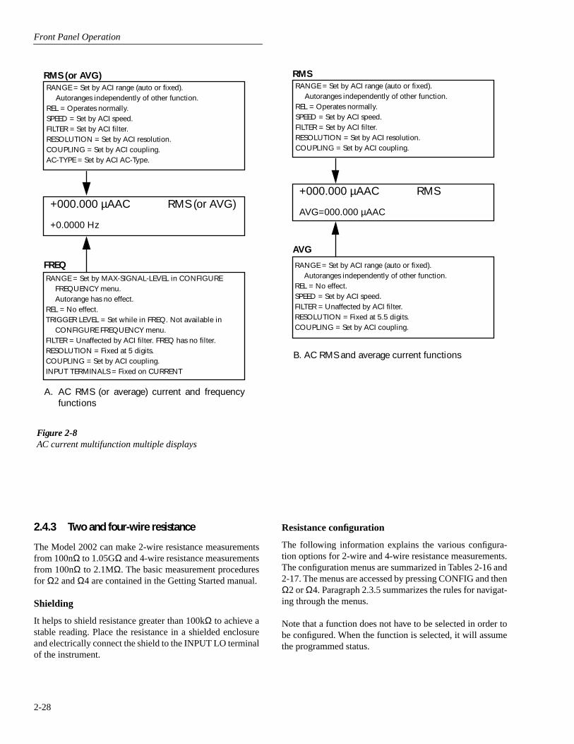
Front Panel Operation
2-28
2.4.3 Two and four-wire resistance
The Model 2002 can make 2-wire resistance measurementsfrom 100nΩ to 1.05GΩ and 4-wire resistance measurementsfrom 100nΩ to 2.1MΩ. The basic measurement proceduresfor Ω2 and Ω4 are contained in the Getting Started manual.
Shielding
It helps to shield resistance greater than 100kΩ to achieve astable reading. Place the resistance in a shielded enclosureand electrically connect the shield to the INPUT LO terminalof the instrument.
Figure 2-8AC current multifunction multiple displays
RMS (or AVG)RANGE = Set by ACI range (auto or fixed).
Autoranges independently of other function.REL = Operates normally.SPEED = Set by ACI speed.FILTER = Set by ACI filter.RESOLUTION = Set by ACI resolution.COUPLING = Set by ACI coupling.AC-TYPE = Set by ACI AC-Type.
FREQRANGE = Set by MAX-SIGNAL-LEVEL in CONFIGURE
FREQUENCY menu.Autorange has no effect.
REL = No effect.TRIGGER LEVEL = Set while in FREQ. Not available in
CONFIGURE FREQUENCY menu.FILTER = Unaffected by ACI filter. FREQ has no filter.RESOLUTION = Fixed at 5 digits.COUPLING = Set by ACI coupling.INPUT TERMINALS = Fixed on CURRENT
+000.000 µAAC RMS (or AVG)
+0.0000 Hz
A. AC RMS (or average) current and frequencyfunctions
B. AC RMS and average current functions
RMSRANGE = Set by ACI range (auto or fixed).
Autoranges independently of other function.REL = Operates normally.SPEED = Set by ACI speed.FILTER = Set by ACI filter.RESOLUTION = Set by ACI resolution.COUPLING = Set by ACI coupling.
AVG
RANGE = Set by ACI range (auto or fixed).Autoranges independently of other function.
REL = No effect.SPEED = Set by ACI speed.FILTER = Unaffected by ACI filter.RESOLUTION = Fixed at 5.5 digits.COUPLING = Set by ACI coupling.
+000.000 µAAC RMS
AVG=000.000 µAAC
Resistance configuration
The following information explains the various configura-tion options for 2-wire and 4-wire resistance measurements.The configuration menus are summarized in Tables 2-16 and2-17. The menus are accessed by pressing CONFIG and thenΩ2 or Ω4. Paragraph 2.3.5 summarizes the rules for navigat-ing through the menus.
Note that a function does not have to be selected in order tobe configured. When the function is selected, it will assumethe programmed status.
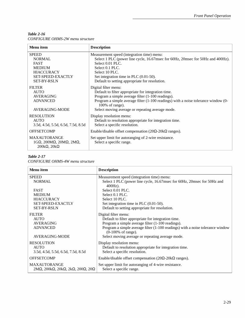
Front Panel Operation
2-29
Table 2-16CONFIGURE OHMS-2W menu structure
Menu item Description
SPEEDNORMALFASTMEDIUMHIACCURACYSET-SPEED-EXACTLYSET-BY-RSLN
Measurement speed (integration time) menu:Select 1 PLC (power line cycle, 16.67msec for 60Hz, 20msec for 50Hz and 400Hz).Select 0.01 PLC.Select 0.1 PLC.Select 10 PLC.Set integration time in PLC (0.01-50).Default to setting appropriate for resolution.
FILTERAUTOAVERAGINGADVANCED
AVERAGING-MODE
Digital filter menu:Default to filter appropriate for integration time.Program a simple average filter (1-100 readings).Program a simple average filter (1-100 readings) with a noise tolerance window (0-
100% of range).Select moving average or repeating average mode.
RESOLUTIONAUTO3.5d, 4.5d, 5.5d, 6.5d, 7.5d, 8.5d
Display resolution menu:Default to resolution appropriate for integration time.Select a specific resolution.
OFFSETCOMP Enable/disable offset compensation (20Ω-20kΩ ranges).
MAXAUTORANGE1GΩ, 200MΩ, 20MΩ, 2MΩ,
200kΩ, 20kΩ
Set upper limit for autoranging of 2-wire resistance.Select a specific range.
Table 2-17CONFIGURE OHMS-4W menu structure
Menu item Description
SPEEDNORMAL
FASTMEDIUMHIACCURACYSET-SPEED-EXACTLYSET-BY-RSLN
Measurement speed (integration time) menu:Select 1 PLC (power line cycle, 16.67msec for 60Hz, 20msec for 50Hz and
400Hz).Select 0.01 PLC.Select 0.1 PLC.Select 10 PLC.Set integration time in PLC (0.01-50).Default to setting appropriate for resolution.
FILTERAUTOAVERAGINGADVANCED
AVERAGING-MODE
Digital filter menu:Default to filter appropriate for integration time.Program a simple average filter (1-100 readings).Program a simple average filter (1-100 readings) with a noise tolerance window
(0-100% of range).Select moving average or repeating average mode.
RESOLUTIONAUTO3.5d, 4.5d, 5.5d, 6.5d, 7.5d, 8.5d
Display resolution menu:Default to resolution appropriate for integration time.Select a specific resolution.
OFFSETCOMP Enable/disable offset compensation (20Ω-20kΩ ranges).
MAXAUTORANGE2MΩ, 200kΩ, 20kΩ, 2kΩ, 200Ω, 20Ω
Set upper limit for autoranging of 4-wire resistance.Select a specific range.

Front Panel Operation
2-30
SPEED
The SPEED parameter sets the integration time of the A/Dconverter, the period of time the input signal is measured(also known as aperture). It is discussed in paragraph 2.4.1,DC and AC voltage. Only the differences for 2-wire and 4-wire resistance are noted here.
SET-BY-RSLN: This parameter optimizes the integrationtime for the present resolution setting. The defaults for set-by-resolution integration times of Ω2 and Ω4 are listed inTable 2-18.
Table 2-18Ω2 and Ω4 integration time set-by-resolution
Resolution Integration time
3.5d, 4.5d5.5d6.5d7.5d8.5d
0.01 PLC0.02 PLC0.10 PLC1.00 PLC10.00 PLC
Note: If the integration time is SET-BY-RSLN and the resolution AUTO, the integration time will be 1.0 PLC and the resolution 7.5 digits.
FILTER
FILTER lets you set the digital filter response. The filtermenu is available from the function configuration menus (i.e.CONFIGURE OHMS-2W) or by pressing CONFIGUREFILTER with the desired function already selected. All of theparameters (menu items) for FILTER are explained in para-graph 2.9. Since the AUTO parameter has specific effects onΩ2 and Ω4, it is covered here.
AUTO: This parameter for a digital filter optimizes its usefor the present measurement function. The defaults for auto-matic filtering of Ω2 and Ω4 are listed in Table 2-19.
RESOLUTION
The RESOLUTION parameter sets the display resolution. Itis discussed in paragraph 2.4.1, DC and AC voltage. Only thedifferences for Ω2 and Ω4 are noted here.
Note that all scientific notation displays are 7-1/2 digits.Labels on the far right, such as channel number, may beomitted to provide the desired precision.
Table 2-19Ω2 and Ω4 auto filter
Measurement function State Type Rdg.
Noise tolerance
Avg. Mode
2-wire resistance4-wire resistance
OnOn
AdvancedAdvanced
1010
1.0%1.0%
MovingMoving

Front Panel Operation
2-31
AUTO: Refer to Table 2-20 for the resolution associatedwith the integration time.
OFFSETCOMP
Offset compensation is used to compensate for voltagepotentials, such as thermal offsets, across the device undertest. This feature eliminates errors due to a low level externalvoltage source configured in series with the unknown resis-tor. Offsets up to ±0.2V on the 20Ω and 200Ω ranges, andfrom -0.2V to +2V on the 2kΩ and 20kΩ ranges can be cor-rected with offset compensation. Offset compensation isavailable for 2- and 4-wire resistance measurements.
During offset compensated resistance measurements, theModel 2002 performs the following steps for each A/D con-version:
1. Makes a normal resistance measurement of the device.In general, this consists of sourcing a current throughthe device, and measuring the voltage drop across thedevice.
2. Turns off the internal current source and again measuresthe voltage drop across the device. This is the voltagecaused by an external device.
3. Calculates and displays the corrected resistance value.
Offset compensation not only corrects for small errorvoltages in the measurement circuit, but it also compensatesfor thermal voltages generated within the Model 2002.Consequently, the use of offset compensation yields greateraccuracy.
The OFFSETCOMP selections are explained as follows:
ON: Enables offset compensation
OFF: Disables offset compensation
Offset compensated readings are indicated by “OCmp” tothe right of the reading.
Table 2-20Ω2 and Ω4 auto resolution
Integration time Resolution
0.01 to <0.02 PLC0.02 to <0.10 PLC0.10 to <1.00 PLC1.00 to <10.00 PLC10.00 to 50 PLC
4.5d5.5d6.5d7.5d8.5d
Note: If the resolution is AUTO and the integration time SET-BY-RSLN, the resolution will be 7.5 digits and the integration time 1.0 PLC.
Note that the offset compensation settings of the ohms func-tions are discrete. Thus, enabling offset compensation in 2-wire ohms has no effect on 4-wire ohms.
MAXAUTORANGE
By setting an upper limit on autoranging, you can preventchanges to ranges that you do not want to use. This speeds upthe reading rate while still using auto-ranging.
MAXAUTORANGE selections for Ω2 and Ω4:
1GΩ, 200MΩ, 20MΩ, 2MΩ, 200kΩ or 20kΩ: Sets maxi-mum autorange limit for Ω2.
2MΩ, 200kΩ, 20kΩ, 2kΩ, 200Ω or 20Ω: Sets maximumautorange limit for Ω4.
Multiple displays
There are three multiple displays available just for the resis-tance functions:
• Source current
• Voltage drop
• Lead resistance (Ω4 only)
Source current: This is the value of the current beingsourced for the present resistance range. It is based on thecalibration constants and is shown as follows:
Source Current = 0.0000 mA
Voltage drop: This display shows the voltage drop across theresistance under test. It is shown as follows:
Voltage Drop = 0.0000 mV
This voltage drop is determined by multiplying the sourcecurrent by the resistance and does not include voltage contri-butions from other current that may be flowing through theresistance.
Lead Resistance: This display, available only for 4-wireohms, shows the value of the lead resistance that is beingnulled by using the Ω4 function. You can use the informationto decide if a 4-wire measurement is necessary. The displayis as follows:
Lead Resistance = 0.0000 Ω
If the lead resistance exceeds 1kΩ, the display is:
2-WIRE OHMS measurement overflow
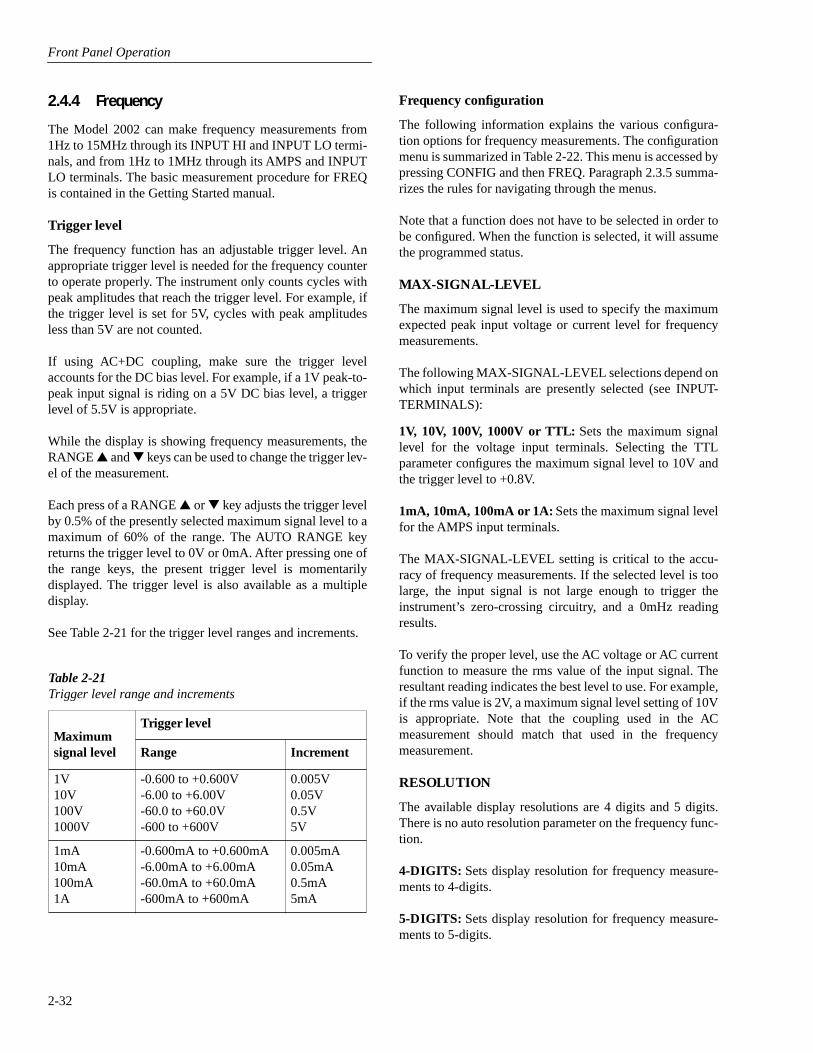
Front Panel Operation
2-32
2.4.4 Frequency
The Model 2002 can make frequency measurements from1Hz to 15MHz through its INPUT HI and INPUT LO termi-nals, and from 1Hz to 1MHz through its AMPS and INPUTLO terminals. The basic measurement procedure for FREQis contained in the Getting Started manual.
Trigger level
The frequency function has an adjustable trigger level. Anappropriate trigger level is needed for the frequency counterto operate properly. The instrument only counts cycles withpeak amplitudes that reach the trigger level. For example, ifthe trigger level is set for 5V, cycles with peak amplitudesless than 5V are not counted.
If using AC+DC coupling, make sure the trigger levelaccounts for the DC bias level. For example, if a 1V peak-to-peak input signal is riding on a 5V DC bias level, a triggerlevel of 5.5V is appropriate.
While the display is showing frequency measurements, theRANGE and keys can be used to change the trigger lev-el of the measurement.
Each press of a RANGE or key adjusts the trigger levelby 0.5% of the presently selected maximum signal level to amaximum of 60% of the range. The AUTO RANGE keyreturns the trigger level to 0V or 0mA. After pressing one ofthe range keys, the present trigger level is momentarilydisplayed. The trigger level is also available as a multipledisplay.
See Table 2-21 for the trigger level ranges and increments.
Frequency configuration
The following information explains the various configura-tion options for frequency measurements. The configurationmenu is summarized in Table 2-22. This menu is accessed bypressing CONFIG and then FREQ. Paragraph 2.3.5 summa-rizes the rules for navigating through the menus.
Note that a function does not have to be selected in order tobe configured. When the function is selected, it will assumethe programmed status.
MAX-SIGNAL-LEVEL
The maximum signal level is used to specify the maximumexpected peak input voltage or current level for frequencymeasurements.
The following MAX-SIGNAL-LEVEL selections depend onwhich input terminals are presently selected (see INPUT-TERMINALS):
1V, 10V, 100V, 1000V or TTL: Sets the maximum signallevel for the voltage input terminals. Selecting the TTLparameter configures the maximum signal level to 10V andthe trigger level to +0.8V.
1mA, 10mA, 100mA or 1A: Sets the maximum signal levelfor the AMPS input terminals.
The MAX-SIGNAL-LEVEL setting is critical to the accu-racy of frequency measurements. If the selected level is toolarge, the input signal is not large enough to trigger theinstrument’s zero-crossing circuitry, and a 0mHz readingresults.
To verify the proper level, use the AC voltage or AC currentfunction to measure the rms value of the input signal. Theresultant reading indicates the best level to use. For example,if the rms value is 2V, a maximum signal level setting of 10Vis appropriate. Note that the coupling used in the ACmeasurement should match that used in the frequencymeasurement.
RESOLUTION
The available display resolutions are 4 digits and 5 digits.There is no auto resolution parameter on the frequency func-tion.
4-DIGITS: Sets display resolution for frequency measure-ments to 4-digits.
5-DIGITS: Sets display resolution for frequency measure-ments to 5-digits.
Table 2-21Trigger level range and increments
Maximum signal level
Trigger level
Range Increment
1V10V100V1000V
-0.600 to +0.600V -6.00 to +6.00V -60.0 to +60.0V -600 to +600V
0.005V0.05V0.5V5V
1mA10mA100mA1A
-0.600mA to +0.600mA -6.00mA to +6.00mA -60.0mA to +60.0mA -600mA to +600mA
0.005mA0.05mA0.5mA5mA
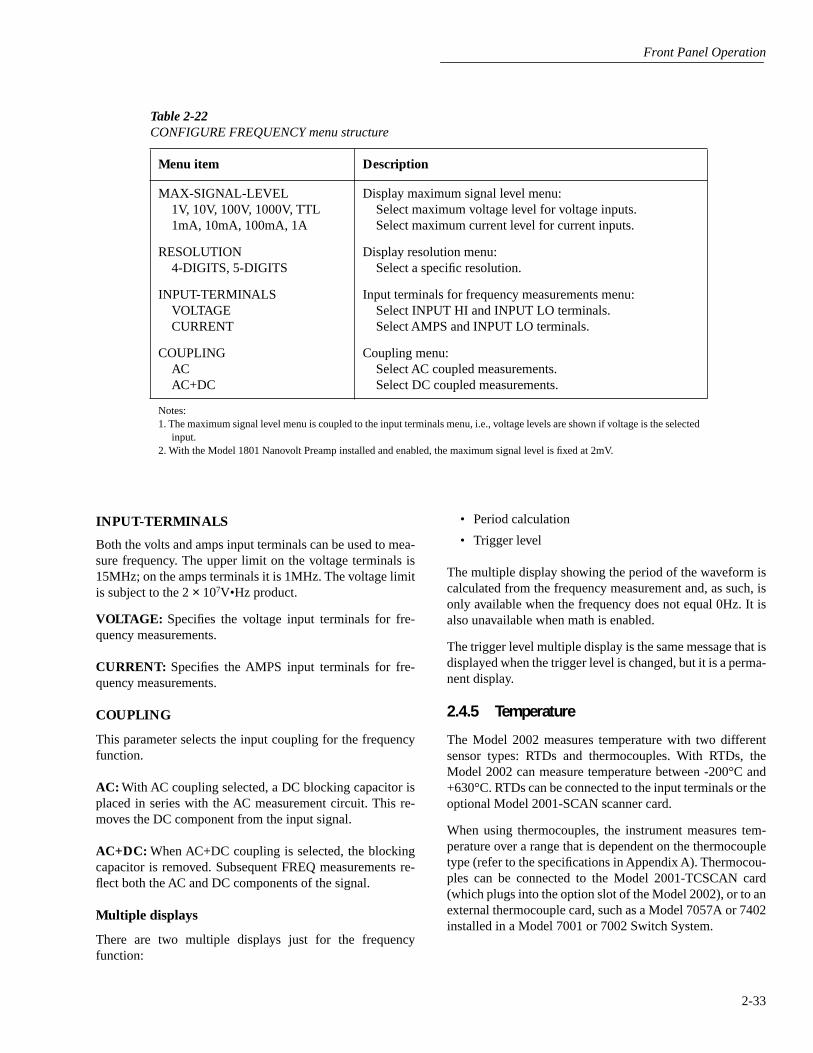
Front Panel Operation
2-33
INPUT-TERMINALS
Both the volts and amps input terminals can be used to mea-sure frequency. The upper limit on the voltage terminals is15MHz; on the amps terminals it is 1MHz. The voltage limitis subject to the 2 × 10⁷V•Hz product.
VOLTAGE: Specifies the voltage input terminals for fre-quency measurements.
CURRENT: Specifies the AMPS input terminals for fre-quency measurements.
COUPLING
This parameter selects the input coupling for the frequencyfunction.
AC: With AC coupling selected, a DC blocking capacitor isplaced in series with the AC measurement circuit. This re-moves the DC component from the input signal.
AC+DC: When AC+DC coupling is selected, the blockingcapacitor is removed. Subsequent FREQ measurements re-flect both the AC and DC components of the signal.
Multiple displays
There are two multiple displays just for the frequencyfunction:
Table 2-22CONFIGURE FREQUENCY menu structure
Menu item Description
MAX-SIGNAL-LEVEL1V, 10V, 100V, 1000V, TTL1mA, 10mA, 100mA, 1A
Display maximum signal level menu:Select maximum voltage level for voltage inputs.Select maximum current level for current inputs.
RESOLUTION4-DIGITS, 5-DIGITS
Display resolution menu:Select a specific resolution.
INPUT-TERMINALSVOLTAGECURRENT
Input terminals for frequency measurements menu:Select INPUT HI and INPUT LO terminals.Select AMPS and INPUT LO terminals.
COUPLINGACAC+DC
Coupling menu:Select AC coupled measurements.Select DC coupled measurements.
Notes:1. The maximum signal level menu is coupled to the input terminals menu, i.e., voltage levels are shown if voltage is the selected
input.2. With the Model 1801 Nanovolt Preamp installed and enabled, the maximum signal level is fixed at 2mV.
• Period calculation
• Trigger level
The multiple display showing the period of the waveform iscalculated from the frequency measurement and, as such, isonly available when the frequency does not equal 0Hz. It isalso unavailable when math is enabled.
The trigger level multiple display is the same message that isdisplayed when the trigger level is changed, but it is a perma-nent display.
2.4.5 Temperature
The Model 2002 measures temperature with two differentsensor types: RTDs and thermocouples. With RTDs, theModel 2002 can measure temperature between -200°C and+630°C. RTDs can be connected to the input terminals or theoptional Model 2001-SCAN scanner card.
When using thermocouples, the instrument measures tem-perature over a range that is dependent on the thermocoupletype (refer to the specifications in Appendix A). Thermocou-ples can be connected to the Model 2001-TCSCAN card(which plugs into the option slot of the Model 2002), or to anexternal thermocouple card, such as a Model 7057A or 7402installed in a Model 7001 or 7002 Switch System.

Front Panel Operation
2-34
Temperature measurements
The basic measurement procedure for 4-wire RTD tempera-ture measurements is contained in the Getting Started manu-al. The procedure for measuring temperature with 3-wire and2-wire RTDs is similar. Connection diagrams for these RTDsare provided by Figures 2-9 and 2-10. Be sure that the tem-perature function is configured for the correct sensor type.Use the 4-WIRE-RTD selection for a 3-wire RTD sensor.
If using the Model 2001-TCSCAN to make thermocoupletemperature measurements, refer to its instruction manualfor connection information and the measurement procedure.If using the Model 7057A or 7402, connect the output of thethermocouple card to INPUT HI and LO of the Model 2002and refer to its instruction manual for operating information.
The Models 7057A and 7402 use Channel 1 as the referencejunction, and must be configured on the Model 2002 for volt-age references and offset.
Temperature configuration
The following information explains the various configura-tion options for temperature measurements. The configura-tion menu is summarized in Table 2-23. This menu isaccessed by pressing CONFIG and then TEMP. Paragraph2.3.5 summarizes the rules for navigating through the menus.
Note that a function does not have to be selected in order tobe configured. When the function is selected, it will assumethe programmed status.
Figure 2-93-wire RTD temperature measurements
NEXT
DISPLAY
PREV
POWER
DCV ACV DCI ACI Ω2 Ω4 FREQ TEMP
REL TRIG STORE RECALL
INFO LOCAL CHAN SCAN CONFIG MENU EXIT ENTER
RANGE
AUTOFILTER MATH
RANGE
2002 MULTIMETER
SENSE
Ω 4 WIRE
HI
INPUT
LOINPUTS
CAL
500V
PEAK
F R
FRONT/REAR
2A 250V
AMPS
350V
PEAK1100V
PEAK
Model 2002
PlatinumRTD
Input HI
Input LO
Sense Ω4-wire LO
8680RTD PROBE ADAPTER
RANGE: -220°C TO 630°C -360°F TO 1100°F
MADEIN
U.S.A.
42VPEAK
RTD
HISENSE
HI LOSENSE
LO
Input HI
Sense Ω4-wire LO
Input LO
1 2 3 4
Short
Short
Short
+000.00 °C4W-RTD type : PT385
+000.00 °C4W-RTD type : PT385
A. Connections to Banana Jacks
WARNING : To avoid a shock hazard and possibleinstrument damage, do not use the Model 8680 RTDProbe Adapter to measure voltages exceeding 30VRMS, 42.4V peak.
B. Connections to Terminal Block
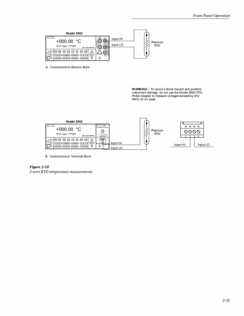
Front Panel Operation
2-35
Figure 2-102-wire RTD temperature measurements
NEXT
DISPLAY
PREV
POWER
DCV ACV DCI ACI Ω2 Ω4 FREQ TEMP
REL TRIG STORE RECALL
INFO LOCAL CHAN SCAN CONFIG MENU EXIT ENTER
RANGE
AUTOFILTER MATH
RANGE
2002 MULTIMETER
SENSE
Ω 4 WIRE
HI
INPUT
LOINPUTS
CAL
500V
PEAK
F R
FRONT/REAR
2A 250V
AMPS
350V
PEAK1100V
PEAK
Model 2002
PlatinumRTD
Input HI
Input LO
A. Connections to Banana Jacks
WARNING : To avoid a shock hazard and possibleinstrument damage, do not use the Model 8680 RTDProbe Adapter to measure voltages exceeding 30VRMS, 42.4V peak.
NEXT
DISPLAY
PREV
POWER
DCV ACV DCI ACI Ω2 Ω4 FREQ TEMP
REL TRIG STORE RECALL
INFO LOCAL CHAN SCAN CONFIG MENU EXIT ENTER
RANGE
AUTOFILTER MATH
RANGE
2002 MULTIMETER
SENSE
Ω 4 WIRE
HI
INPUT
LOINPUTS
CAL
500V
PEAK
F R
FRONT/REAR
2A 250V
AMPS
350V
PEAK1100V
PEAK
Model 2002
PlatinumRTD
Input HI
Input LO
B. Connections to Terminal Block
8680RTD PROBE ADAPTER
RANGE: -220°C TO 630°C -360°F TO 1100°F
MADEIN
U.S.A.
42VPEAK
RTD
HISENSE
HI LOSENSE
LO
Input HI Input LO
1 2 3 4
+000.00 °CRTD type : PT385
+000.00 °CRTD type : PT385

Front Panel Operation
2-36
Table 2-23CONFIG TEMPERATURE menu structure
Menu item Description
SENSOR4-WIRE-RTD
PT100D100F100USERPT385PT3916SPRTD
RTD PT100D100F100USERPT385PT3916SPRTD
THERMOCOUPLETHERMOCOUPLE-TYPEREF-JUNCTIONS
CONFIGUREACQUIRE-REF-TEMP
INTERNAL-TEMP
Sensor type menu:4-wire RTD type menu:
Select PT100 type.Select D100 type.Select F100 type.Use to set R-zero, alpha, beta, delta.Select PT385 type.Select PT3916 type.Select SPRTD type.
2-wire RTD type menu:Select PT100 type.Select D100 type.Select F100 type.Use to set R-zero, alpha, beta, delta.Select PT385 type.Select PT3916 type.Select SPRTD type.
Thermocouple setup menu:Select desired thermocouple type (J, K, T, E, R, S, B, N).Configure reference junction menu (JCN1 thru JCN5):
Configure simulated or real junction.Acquire reference temperature.
Select internal temperature transducer.
UNITSDEG-C, DEG-F, K
Temperature units menu:Select desired temperature units.
SPEEDNORMAL
FASTMEDIUMHIACCURACYSET-SPEED-EXACTLYSET-BY-RSLN
Measurement speed (integration time) menu:Select 1 PLC (power line cycle, 16.67msec for 60Hz, 20msec for
50Hz and 400Hz).Select 0.01 PLC.Select 0.1 PLC.Select 10 PLC.Set integration time in PLC (0.01-50).Default to setting appropriate for resolution.
FILTERAUTOAVERAGINGAVERAGING-MODE
Digital filter menu:Default to filter appropriate for integration time.Select simple average filter (1-100 readings).Select moving average or repeating average mode.
RESLNAUTO1°, 0.1°, 0.01°, 0.001°
Display resolution menu:Default to resolution appropriate for sensor.Select a specific resolution.
Note: With the Model 1801 Nanovolt Preamp installed and enabled, the SENSOR menu item is used for differential thermocouple configuration.

Front Panel Operation
2-37
SENSOR
This parameter is used to select the temperature sensor.
4-WIRE-RTD or RTD:
If using a 4-wire or 3-wire RTDsensor, select 4-WIRE-RTD. If using a 2-wire RTD, selectRTD. Selecting an RTD sensor displays the options for RTDstandards. Five are configured for common RTDs and thesixth allows you to enter your own RTD factors:
• PT100, D100, F100, PT385 and PT3916 — Selects thefollowing default parameters for the RTD standards:
• USER — This selection allows you to change one ormore of the RTD factors listed in the above table. Theequation using the factors are shown in Figure 2-11.
SPRTD:
Choosing type SPRTD takes you to the SPRTDCOEFFICIENTS menu, which allows you to program thefollowing parameters:
R-ZERO: RTD 0˚C resistance valueA4: set A4 coefficientB4: set B4 coefficientA7: set A7 coefficientB7: set B7 coefficientC7: set C7 coefficient
The ITS-90 standard provides two reference equations forStandard Platinum Resistance Thermometers covering thetemperature range 18.8033K to 1234.93K. A single SPRTD,however, usually cannot be used to cover the entire range.The temperature range is therefore broken up into severalsubranges. These subranges depend on the calibration pointsof the temperature scale and are based on the melting or tri-ple points of various pure substances. For an exact list of theelements needed and details on RTD calibration, refer toNIST Technical Note 1265 "Guidelines For Realizing theInternational Temperature Scale of 1990". In each subrange,the calibration constants required for that range are listed.
An SPRTD as supplied from the manufacturer will comewith a certificate of calibration that lists the calibrationconstants and the temperature range supported. In all casesexcept subranges #4 and #7, translation of the suppliedcoefficients to Model 2002 values will be required. In mostcases, this translation is done simply entering the A value(for example) supplied with the SPRTD into the A4 position(temperatures less than 0˚C) or A7 value (temperaturesabove 0˚C) required by the Model 2002. The same procedureis used for translating the B and, where applicable, Cconstants.
The following table should be helpful in translating SPRTDcoefficients to Model 2002 SPRTD coefficients. The Model2002 supports SPRTD temperatures between 83.805K and933.473K. For any of the subranges below, onlytemperatures within the range from 83.805K to 933.47K willbe measured.
Type Standard Alpha Beta DeltaRZero(
Ω
at 0°C)
PT100D100F100
ITS-90ITS-90ITS-90
0.0038500.0039200.003900
0.108630.106300.11000
1.499901.497101.49589
100.00000100.00000100.00000
PT385PT3916
IPTS-68IPTS-68
0.0038500.003916
0.111000.11600
1.507001.50594
100.00000100.00000
Coefficients RTD coefficients to Model 2002 coefficients
Subrange #1: 13.8033K - 273.16K Not applicable
Subrange #2: 24.5561K - 273.16K A2 to A4, B2 to B4
Subrange #3: 54.3584K - 273.16K A3 to A4, B3 to B4
Subrange #4: 83.8058K - 273.16K No substitution needed
Subrange #5: 234.3156K - 302.9146K A5 to A4, A5 to A7, B5 to B4B5 to B7, Set C7 = 0. A5 value entered for both A4 and A7; B5 value entered for both B4 and B7
Subrange #6: 273.15K - 1234.93K Not applicable
Subrange #7: 273.15K - 933.473K No substitution needed
Subrange #8: 273.15K - 692.677K A8 to A7, B8 to B7, Set C7 = 0
Subrange #9: 273.15K - 505.078K A9 to A7, B9 to B7, Set C7 = 0
Subrange #10: 273.15K - 429.7485K A10 to A7, B10 to B7, Set C7 = 0
Subrange #11: 273.15K - 302.9146K A11 to A7, Set B7 = 0, C7 = 0
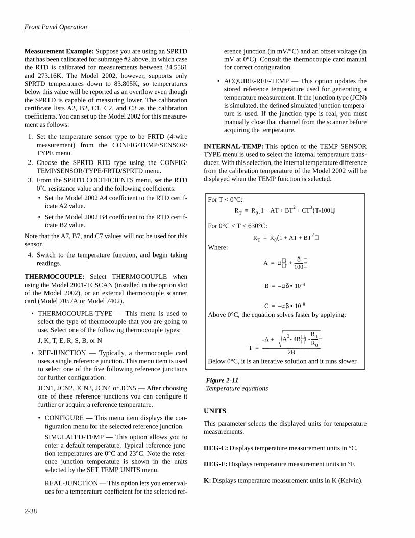
Front Panel Operation
2-38
Measurement Example:
Suppose you are using an SPRTDthat has been calibrated for subrange #2 above, in which casethe RTD is calibrated for measurements between 24.5561and 273.16K. The Model 2002, however, supports onlySPRTD temperatures down to 83.805K, so temperaturesbelow this value will be reported as an overflow even thoughthe SPRTD is capable of measuring lower. The calibrationcertificate lists A2, B2, C1, C2, and C3 as the calibrationcoefficients. You can set up the Model 2002 for this measure-ment as follows:
1. Set the temperature sensor type to be FRTD (4-wiremeasurement) from the CONFIG/TEMP/SENSOR/TYPE menu.
2. Choose the SPRTD RTD type using the CONFIG/TEMP/SENSOR/TYPE/FRTD/SPRTD menu.
3. From the SPRTD COEFFICIENTS menu, set the RTD0˚C resistance value and the following coefficients:
• Set the Model 2002 A4 coefficient to the RTD certif-icate A2 value.
• Set the Model 2002 B4 coefficient to the RTD certif-icate B2 value.
Note that the A7, B7, and C7 values will not be used for thissensor.
4. Switch to the temperature function, and begin takingreadings.
THERMOCOUPLE:
Select THERMOCOUPLE whenusing the Model 2001-TCSCAN (installed in the option slotof the Model 2002), or an external thermocouple scannercard (Model 7057A or Model 7402).
• THERMOCOUPLE-TYPE — This menu is used toselect the type of thermocouple that you are going touse. Select one of the following thermocouple types:
J, K, T, E, R, S, B, or N
• REF-JUNCTION — Typically, a thermocouple carduses a single reference junction. This menu item is usedto select one of the five following reference junctionsfor further configuration:
JCN1, JCN2, JCN3, JCN4 or JCN5 — After choosingone of these reference junctions you can configure itfurther or acquire a reference temperature.
• CONFIGURE — This menu item displays the con-figuration menu for the selected reference junction.
SIMULATED-TEMP — This option allows you toenter a default temperature. Typical reference junc-tion temperatures are 0°C and 23°C. Note the refer-ence junction temperature is shown in the unitsselected by the SET TEMP UNITS menu.
REAL-JUNCTION — This option lets you enter val-ues for a temperature coefficient for the selected ref-
erence junction (in mV/°C) and an offset voltage (inmV at 0°C). Consult the thermocouple card manualfor correct configuration.
• ACQUIRE-REF-TEMP — This option updates thestored reference temperature used for generating atemperature measurement. If the junction type (JCN)is simulated, the defined simulated junction tempera-ture is used. If the junction type is real, you mustmanually close that channel from the scanner beforeacquiring the temperature.
INTERNAL-TEMP:
This option of the TEMP SENSORTYPE menu is used to select the internal temperature trans-ducer. With this selection, the internal temperature differencefrom the calibration temperature of the Model 2002 will bedisplayed when the TEMP function is selected.
UNITS
This parameter selects the displayed units for temperaturemeasurements.
DEG-C:
Displays temperature measurement units in °C.
DEG-F:
Displays temperature measurement units in °F.
K:
Displays temperature measurement units in K (Kelvin).
Figure 2-11Temperature equations
For T < 0°C:
For 0°C < T < 630°C:
Where:
Above 0°C, the equation solves faster by applying:
Below 0°C, it is an iterative solution and it runs slower.
RT R0 1 AT BT2
CT3
T-100( )+ + +[ ]=
RT R0 1 AT BT2
+ +( )=
A α 1 δ100---------+
=
B αδ 10-4•–=
C αβ 10-8•–=
T
A2- 4B 1 -
R
T R 0
------- A + –
2B---------------------------------------------------------=
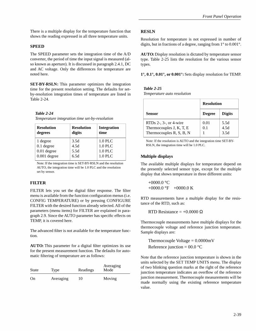
Front Panel Operation
2-39
There is a multiple display for the temperature function thatshows the reading expressed in all three temperature units.
SPEED
The SPEED parameter sets the integration time of the A/Dconverter, the period of time the input signal is measured (al-so known as aperture). It is discussed in paragraph 2.4.1, DCand AC voltage. Only the differences for temperature arenoted here.
SET-BY-RSLN:
This parameter optimizes the integrationtime for the present resolution setting. The defaults for set-by-resolution integration times of temperature are listed inTable 2-24.
FILTER
FILTER lets you set the digital filter response. The filtermenu is available from the function configuration menus (i.e.CONFIG TEMPERATURE) or by pressing CONFIGUREFILTER with the desired function already selected. All of theparameters (menu items) for FILTER are explained in para-graph 2.9. Since the AUTO parameter has specific effects onTEMP, it is covered here.
The advanced filter is not available for the temperature func-tion.
AUTO:
This parameter for a digital filter optimizes its usefor the present measurement function. The defaults for auto-matic filtering of temperature are as follows:
AveragingState Type Readings Mode
On Averaging 10 Moving
Table 2-24
Temperature integration time set-by-resolution
Resolution degrees
Resolution digits
Integration time
1 degree0.1 degree0.01 degree0.001 degree
3.5d4.5d5.5d6.5d
1.0 PLC1.0 PLC1.0 PLC1.0 PLC
Note: If the integration time is SET-BY-RSLN and the resolution AUTO, the integration time will be 1.0 PLC and the resolution set by sensor.
RESLN
Resolution for temperature is not expressed in number ofdigits, but in fractions of a degree, ranging from 1° to 0.001°.
AUTO:
Display resolution is dictated by temperature sensortype. Table 2-25 lists the resolution for the various sensortypes.
1°, 0.1°, 0.01°, or 0.001°:
Sets display resolution for TEMP.
Multiple displays
The available multiple displays for temperature depend onthe presently selected sensor type, except for the multipledisplay that shows temperature in three different units:
+0000.0 °C+0000.0 °F +0000.0 K
RTD measurements have a multiple display for the resis-tance of the RTD, such as:
RTD Resistance = +0.0000
Ω
Thermocouple measurements have multiple displays for thethermocouple voltage and reference junction temperature.Sample displays are:
Thermocouple Voltage = 0.0000mVReference junction = 00.0 °C
Note that the reference junction temperature is shown in theunits selected by the SET TEMP UNITS menu. The displayof two blinking question marks at the right of the referencejunction temperature indicates an overflow of the referencejunction measurement. Thermocouple measurements will bemade normally using the existing reference temperaturevalue.
Table 2-25
Temperature auto resolution
Sensor
Resolution
Degree Digits
RTDs 2-, 3-, or 4-wireThermocouples J, K, T, EThermocouples R, S, B, N
0.010.11
5.5d4.5d3.5d
Note: If the resolution is AUTO and the integration time SET-BY-RSLN, the integration time will be 1.0 PLC.
Front Panel Operation
2-40
2.5 Range
The selected measurement range affects both the ultimateresolution and accuracy of the measurements as well as themaximum signal that can be measured. The range setting(fixed or auto) for each measurement function is saved whenchanging functions.
2.5.1 Display resolution
The display resolution of a Model 2002 reading depends onthe selected range and the resolution setting. The default andmaximum display resolutions for every range on each func-tion are included in the specifications of Appendix A.
You can set the display resolution, as described in paragraph2.4.
2.5.2 Maximum readings
The full scale readings for every range on each function areincluded in the specifications of Appendix A. Input valuesmore than the maximum reading listed cause the “Overflow”message to be displayed.
2.5.3 Manual ranging
To select a manual range, simply press the RANGE
or
key. The instrument changes one range per key press. Theselected range is displayed on the bottom line of the display.
If the instrument displays the “Overflow” message on a par-ticular range, select a higher range until an on-range readingis displayed. Use the lowest range possible without causingan overflow to ensure best accuracy and resolution.
Note that the frequency and temperature functions have justone range. For the frequency functions, the RANGE
and
keys increase and decrease the trigger level by 0.5%. Ontemperature the keys have no effect.
2.5.4 Autoranging
To enable autoranging, press the AUTO key. The AUTOannunciator turns on when autoranging is selected. Whileautoranging is selected, the instrument automaticallychooses the best range to measure the applied signal.
NOTE
Autoranging should not be used when op-timum speed is required.
Note that up-ranging occurs at 105% of range, while down-ranging occurs at 10% of range.
To cancel autoranging, press AUTO or the RANGE
or
key. Pressing AUTO to cancel autoranging leaves the instru-ment on the present range.
Pressing the RANGE
key when the instrument has auto-ranged to the lowest range displays the following momentarytypical message and leaves the instrument in autorange:
Range at minimum: 200 mVDC
The instrument operates similarly if the RANGE
key ispressed when the instrument has autoranged to the highestrange.
For the frequency function, pressing the AUTO key returnsthe trigger level to 0.0V. The AUTO key has no effect in thetemperature function.
2.6 Relative
The rel (relative) operation subtracts a reference value fromactual readings. When rel is enabled by the REL key, the in-strument uses the present reading as a relative value. Subse-quent readings will be the difference between the actualinput value and the rel value. You can also enter and enable arelative value from the CONFIG-REL display (see para-graph 2.6.1).
A rel value can be established for each measurement func-tion. The state and value of rel for each measurement func-tion are saved when changing functions.
Once a rel value is established for a measurement function,the value is the same for all ranges. For example, if 150V isset as a rel value on the 200V range, the rel is also 150V onthe 1000V, 20V, 2V, and 200mV ranges.
A relative value can be as large as the highest range for theparticular function. Table 2-26 lists the allowable range of relvalues for each function.
Selecting a range that cannot accommodate the rel valuedoes not cause an overflow condition, but it also does notincrease the maximum allowable input for that range. Forexample, on the 2mA range, the Model 2002 still overflowsfor a 2.1mA input.
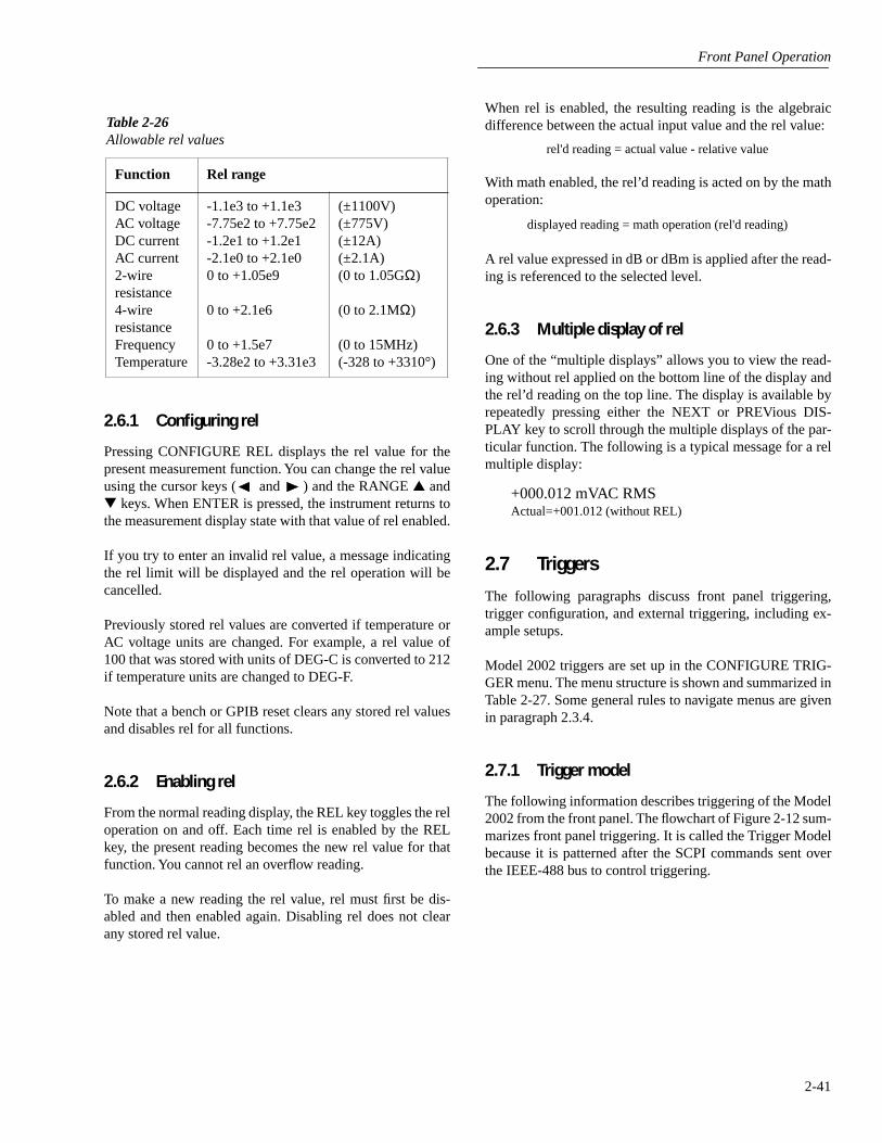
Front Panel Operation
2-41
2.6.1 Configuring rel
Pressing CONFIGURE REL displays the rel value for thepresent measurement function. You can change the rel valueusing the cursor keys ( and ) and the RANGE and keys. When ENTER is pressed, the instrument returns tothe measurement display state with that value of rel enabled.
If you try to enter an invalid rel value, a message indicatingthe rel limit will be displayed and the rel operation will becancelled.
Previously stored rel values are converted if temperature orAC voltage units are changed. For example, a rel value of100 that was stored with units of DEG-C is converted to 212if temperature units are changed to DEG-F.
Note that a bench or GPIB reset clears any stored rel valuesand disables rel for all functions.
2.6.2 Enabling rel
From the normal reading display, the REL key toggles the reloperation on and off. Each time rel is enabled by the RELkey, the present reading becomes the new rel value for thatfunction. You cannot rel an overflow reading.
To make a new reading the rel value, rel must first be dis-abled and then enabled again. Disabling rel does not clearany stored rel value.
When rel is enabled, the resulting reading is the algebraicdifference between the actual input value and the rel value:
With math enabled, the rel’d reading is acted on by the mathoperation:
A rel value expressed in dB or dBm is applied after the read-ing is referenced to the selected level.
2.6.3 Multiple display of rel
One of the “multiple displays” allows you to view the read-ing without rel applied on the bottom line of the display andthe rel’d reading on the top line. The display is available byrepeatedly pressing either the NEXT or PREVious DIS-PLAY key to scroll through the multiple displays of the par-ticular function. The following is a typical message for a relmultiple display:
+000.012 mVAC RMSActual=+001.012 (without REL)
2.7 Triggers
The following paragraphs discuss front panel triggering,trigger configuration, and external triggering, including ex-ample setups.
Model 2002 triggers are set up in the CONFIGURE TRIG-GER menu. The menu structure is shown and summarized inTable 2-27. Some general rules to navigate menus are givenin paragraph 2.3.4.
2.7.1 Trigger model
The following information describes triggering of the Model2002 from the front panel. The flowchart of Figure 2-12 sum-marizes front panel triggering. It is called the Trigger Modelbecause it is patterned after the SCPI commands sent overthe IEEE-488 bus to control triggering.
Table 2-26Allowable rel values
Function Rel range
DC voltageAC voltage DC currentAC current2-wireresistance4-wireresistanceFrequencyTemperature
-1.1e3 to +1.1e3-7.75e2 to +7.75e2-1.2e1 to +1.2e1-2.1e0 to +2.1e00 to +1.05e9
0 to +2.1e6
0 to +1.5e7-3.28e2 to +3.31e3
(±1100V)(±775V)(±12A)(±2.1A)(0 to 1.05GΩ)
(0 to 2.1MΩ)
(0 to 15MHz)(-328 to +3310°)
rel'd reading = actual value - relative value
displayed reading = math operation (rel'd reading)
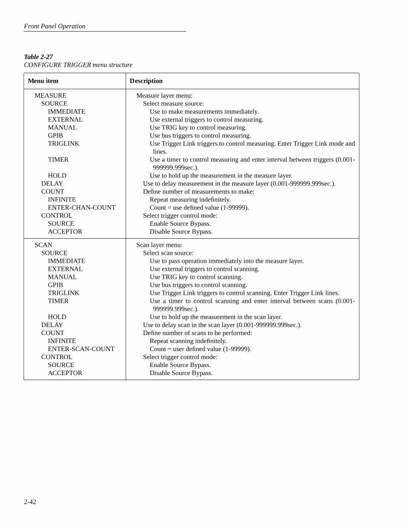
Front Panel Operation
2-42
Table 2-27
CONFIGURE TRIGGER menu structure
Menu item Description
MEASURE
SOURCEIMMEDIATEEXTERNALMANUALGPIBTRIGLINK
TIMER
HOLDDELAYCOUNT
INFINITEENTER-CHAN-COUNT
CONTROLSOURCEACCEPTOR
Measure layer menu:Select measure source:
Use to make measurements immediately.Use external triggers to control measuring.Use TRIG key to control measuring.Use bus triggers to control measuring.Use Trigger Link triggers to control measuring. Enter Trigger Link mode andlines.
Use a timer to control measuring and enter interval between triggers (0.001-999999.999sec.).
Use to hold up the measurement in the measure layer.Use to delay measurement in the measure layer (0.001-999999.999sec.).Define number of measurements to make:
Repeat measuring indefinitely.Count = use defined value (1-99999).
Select trigger control mode:Enable Source Bypass.Disable Source Bypass.
SCANSOURCE
IMMEDIATEEXTERNALMANUALGPIBTRIGLINKTIMER
HOLDDELAYCOUNT
INFINITEENTER-SCAN-COUNT
CONTROLSOURCEACCEPTOR
Scan layer menu:Select scan source:
Use to pass operation immediately into the measure layer.Use external triggers to control scanning.Use TRIG key to control scanning.Use bus triggers to control scanning.Use Trigger Link triggers to control scanning. Enter Trigger Link lines.Use a timer to control scanning and enter interval between scans (0.001-999999.999sec.).
Use to hold up the measurement in the scan layer.Use to delay scan in the scan layer (0.001-999999.999sec.).Define number of scans to be performed:
Repeat scanning indefinitely.Count = user defined value (1-99999).
Select trigger control mode:Enable Source Bypass.Disable Source Bypass.
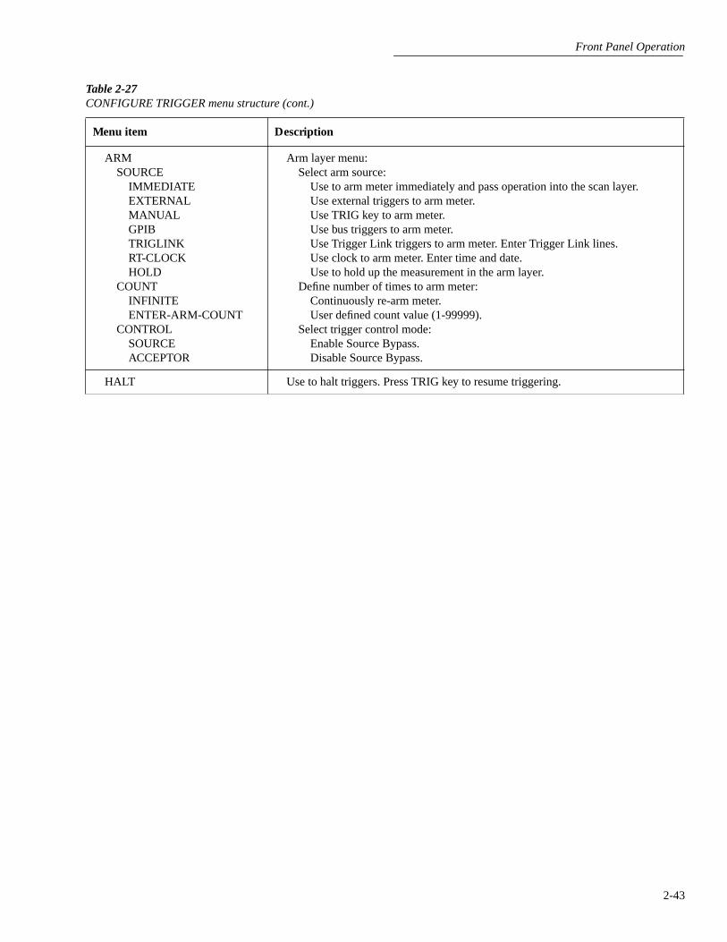
Front Panel Operation
2-43
ARMSOURCE
IMMEDIATEEXTERNALMANUALGPIBTRIGLINKRT-CLOCKHOLD
COUNTINFINITEENTER-ARM-COUNT
CONTROLSOURCEACCEPTOR
Arm layer menu:Select arm source:
Use to arm meter immediately and pass operation into the scan layer.Use external triggers to arm meter.Use TRIG key to arm meter.Use bus triggers to arm meter.Use Trigger Link triggers to arm meter. Enter Trigger Link lines.Use clock to arm meter. Enter time and date.Use to hold up the measurement in the arm layer.
Define number of times to arm meter:Continuously re-arm meter.User defined count value (1-99999).
Select trigger control mode:Enable Source Bypass.Disable Source Bypass.
HALT Use to halt triggers. Press TRIG key to resume triggering.
Table 2-27
CONFIGURE TRIGGER menu structure (cont.)
Menu item Description
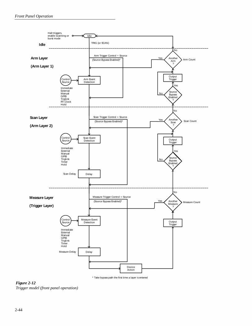
Front Panel Operation
2-44
Idle
Arm Layer
(Arm Layer 1)
Arm EventDetection
ControlSource
IdleNo
Yes
ImmediateExternalManualGPIBTriglinkRT-ClockHold
TRIG (or SCAN)
Arm Trigger Control = Source
(Source Bypass Enabled)*Another
Arm?
OutputTrigger
Arm Count
No
Yes
Scan Layer
(Arm Layer 2)
Scan EventDetection
No
YesScan Trigger Control = Source
(Source Bypass Enabled)*Another
Scan?
Scan Count
No
Yes
DelayScan Delay
Measure EventDetection
No
Yes
Measure Trigger Control = Source
(Source Bypass Enabled)* Measure Count
Measure Delay
DeviceAction
OutputTrigger
ControlSource
OutputTrigger
Delay
ControlSource
Measure Layer
(Trigger Layer)
SourceBypassEnabled
?
SourceBypassEnabled
?
AnotherMeasure
?
Halt triggers,enable scanning orburst mode
ImmediateExternalManualGPIBTriglinkTimerHold
ImmediateExternalManualGPIBTriglinkTimerHold
* Take bypass path the first time a layer is entered
Figure 2-12Trigger model (front panel operation)

Front Panel Operation
2-45
Idle
The instrument is considered to be in the idle state wheneverit is not operating within one of the three layers of the TriggerModel. The front panel ARM indicator is off when the instru-ment is in the idle state. While in the idle state, the instrumentcannot perform any measurement or scanning functions.
From the front panel there are four ways to put the instru-ment into idle:
• Select RESET GPIB from the SAVESETUP option ofthe main menu. Press the TRIG key to take a reading.After each reading, the instrument returns to the idlestate.
• Select HALT from the CONFIGURE TRIGGER menu.Press the TRIG key to resume triggering.
• Enable BURST-MODE from the CONFIGURE DATASTORE menu. This places the instrument in idle untilthe TRIG key is pressed. After each burst acquisitionthe instrument returns to idle.
• Configure an internal or external scan with the SCANkey. Disabling the scan resumes triggering.
Trigger Model Layers
As can be seen in Figure 2-12, the trigger model uses threelayers: the Arm Layer, Scan Layer and Measure Layer. ForIEEE-488 bus operation, these layers are known as Arm Lay-er 1, Arm Layer 2 and the Trigger Layer.
Once the Model 2002 is taken out of the idle state, operationproceeds through the layers of the trigger model down to thedevice action where a measurement occurs.
Control Sources —
In general, each layer contains a controlsource which holds up operation until the programmed eventoccurs. The control sources are described as follows:
• Immediate — With this control source selected, eventdetection is immediately satisfied allowing operation tocontinue.
• Manual — Event detection is satisfied by pressing theTRIG key. Note that the Model 2002 must be taken outof remote before it will respond to the TRIG key. Press-ing LOCAL or sending LOCAL 716 over the bus takesthe instrument out of remote.
• GPIB — Event detection is satisfied when a bus trigger(GET or *TRG) is received by the Model 2002.
• RT-Clock — Event detection in the Arm Layer is satis-fied when the programmed time and date occurs. Thereal-time clock control source is not available in theScan Layer and Measure Layer.
• Timer — Event detection is immediately satisfied onthe initial pass through the layer. Each subsequentdetection is satisfied when the programmed timer inter-val (1 to 999999.999 seconds) elapses. A timer resets toits initial state when operation loops back to a higherlayer (or idle). Note that a timer is not available in theArm Layer.
• External — Event detection is satisfied when an inputtrigger via the EXTERNAL TRIGGER connector isreceived by the Model 2002.
• Triglink — Event detection is satisfied when an inputtrigger via the TRIGGER LINK is received by theModel 2002.
• Hold — With this selection, event detection is not satis-fied by any of the above control source events and oper-ation is held up.
Source Bypasses —
As can be seen in the flowchart, eachlayer has a path that allows operation to loop around the con-trol source. Each path is called a source bypass.
When a source bypass is enabled, and the external or triggerlink (triglink) control source is selected, operation loopsaround the control source on the initial pass through the lay-er. If programmed for another event detection in the layer,the bypass loop will not be in effect though it is still enabled.The bypass loop resets (be in effect) if operation loops backto a higher layer (or idle).
In the Arm Layer and Scan Layer, enabling a source bypassalso enables the respective output trigger. In the Trigger Lay-er, its output trigger is always enabled and occurs after everydevice action. See Output Triggers for more information.
Delays —
The Scan Layer and the Measure Layer have aprogrammable delay (0 to 999999.999 seconds) that is en-forced after an event detection.
Device Action —
The primary device action is a measure-ment. However, the device action could include a functionchange and a channel scan (if scanner is enabled). A channelis scanned (closed) before a measurement is made. Whenscanning internal channels, the previous channel opens andthe next channel closes (break-before-make). Also includedin the device action is the internal settling time delay for therelay.
Output Triggers — In the Arm Layer and Scan Layer theoutput triggers are enabled only if their respective source by-passes are also enabled. If a trigger link (triglink) controlsource is selected, the output trigger pulse is available on theselected TRIGGER LINK output line. For all other control

Front Panel Operation
2-46
source selections, the trigger pulse is available at theMETER COMPLETE connector.
In the Measure Layer, the output trigger is always enabledand occurs after every device action. If the control source isset for external, immediate, manual, GPIB or timer, the out-put trigger pulse is available at the METER COMPLETEconnector. If the trigger link (triglink) control source isselected, output trigger action occurs on the selected TRIG-GER LINK output line as follows:
• If the asynchronous Trigger Link mode is selected, theoutput trigger pulse is available on the programmedoutput line.
• If the semi-synchronous Trigger Link mode is selectedand the source bypass is disabled, the Trigger Link lineis released (goes high).
• If the semi-synchronous Trigger Link mode is selectedand the source bypass is enabled, the Trigger Link lineis pulled down low and then released.
Counters — All three layers use programmable counterswhich allow operation to return to or stay in the respectivelayer. For example, programming the Measure Layer counterfor infinity keeps operation in the Measure Layer. After eachdevice action and subsequent output trigger, operation loopsback to the Trigger Layer control source. A counter resetswhen operation loops back to a higher layer (or idle).
2.7.2 Configuring the measure layer
The measure layer is used for the following operations:
• To select the measuring event (SOURCE) for the instru-ment.
• To delay operation in the measure layer.
• To designate the number of measurements the instru-ment will make (COUNT).
• To enable or disable the Source Bypass.
The measure layer is configured from the MEASURE itemof the CONFIGURE TRIGGER menu, which is displayedby pressing the CONFIG key and then the TRIG key. Gener-al rules for navigating through the menu structure one con-tained in paragraph 2.3.4.
SOURCE
This menu item selects the event that controls the measuresource.
IMMEDIATE: With this selection, events (such as TIMERand EXTERNAL triggers) do not control the measurementinterval. Once the Model 2002 starts measuring, it will takereadings as fast as its measurement configuration allows.
EXTERNAL: With this selection, external triggers are usedto control the measure source. Each trigger stimulus appliedto the Model 2002 performs a device action, as defined bythe trigger model. In addition to a measurement, this mayinclude range changing, filtering, calculations, data storing,scanning, and other operations.
The external trigger is applied to the rear panel “EXTER-NAL TRIGGER” BNC connector. See paragraph 2.7.6 fordetailed information on external triggering.
NOTE
The front panel TRIG key (see MANU-AL) is active with external triggering se-lected. Pressing the TRIG key performs adevice action.
MANUAL: With this selection, the front panel TRIG keycontrols the measure source. A device action is performedwhen the TRIG key is pressed.
NOTE
The front panel TRIG key is active whenEXTERNAL, GPIB, TRIGLINK, or TIM-ER is selected.
GPIB: With this selection, bus triggers control the measuresource. When the Model 2002 receives a bus trigger (GET or*TRG), it performs a device action, as defined by the triggermodel. In addition to a measurement, this may include rangechanging, filtering, calculations, data storing, scanning, andother operations. See Section 3 for detailed information onbus triggers.
NOTE
The front panel TRIG key (see MANU-AL) is active with bus triggering selected.Pressing the TRIG key performs a deviceaction.
TRIGLINK: With this selection, the measure source is con-trolled by the Trigger Link of the Model 2002. Trigger Linkis an enhanced trigger system that uses up to six lines todirect trigger pulses to and from other instruments.
Front Panel Operation
2-47
When the Model 2002 receives a trigger over the TriggerLink, it performs a device action, as defined by the triggermodel. In addition to a measurement, this may include rangechanging, filtering, calculations, data storing, scanning, andother operations.
See paragraph 2.7.7 for details on using the Trigger Link.
NOTE
The front panel TRIG key (see MAN-UAL) is active with the Trigger Linkselected. Pressing the TRIG key performsa device action.
After selecting TRIGLINK as the measurement event, selectone of the following trigger link modes:
• ASYNCHRONOUS — The ascynchronous trigger linkmode is used for trigger configurations that requireinput and output triggers to be routed on separate lines.After selecting this trigger link mode, you will beprompted to select an input line and then an output line.Note that you cannot use the same trigger line for bothinput and output.
• SEMI-SYNCHRONOUS — In this mode, the input andoutput triggers for the Model 2002 are assigned to thesame line. After selecting this trigger link mode, youwill be prompted to select the trigger line.
TIMER: Use the timer to control the time interval betweenmeasurements.
The timer can be set for an interval from 0.001 seconds(1msec) to 999999.999 seconds with 1msec resolution.
After a measurement is triggered to start, the next measure-ment starts at the end of the programmed timer interval. Ifhowever, the programmed timer interval is shorter than thetime it takes to complete a single measurement, the nextmeasurement does not start until the previous one is done.
NOTE
The front panel TRIG key (see MAN-UAL) is active with the timer selected.Pressing the TRIG key after the comple-tion of a measurement starts the next mea-surement (assuming the Model 2002 isprogrammed for another measurement;see COUNT).
HOLD: When HOLD is selected, the measure source is sup-pressed. As a result, measuring is stopped and does not con-tinue until HOLD is cancelled by selecting one of the othermeasure source selections. Select HOLD from the SELECTMEASURE SRC menu by placing the cursor on HOLD andpressing ENTER. The instrument returns to the SETUP mea-sure layer menu.
DELAY
This delay is used to hold up operation in the measure layer.After the measure event occurs, the instrument waits until thedelay period times out (0 - 999999.999sec) before perform-ing a device action.
COUNT
With this selection, you determine the number (count) ofmeasurements per scan sequence. The user programmedcount can be smaller, equal to, or larger than the number ofchannels in the scan list. For example, if the scan list is madeup of four channels, you can program a count of 12. With thiscount value, the instrument repeats the scan three times. Anadvantage of repeating channels (rather than scans) is thatdelays in the scan layer of operation are avoided. The mea-sure delays among all 12 channels are the same.
INFINITE: Use this selection to continuously repeat mea-surements (and looping in the measure layer).
ENTER-CHAN-COUNT: With this selection, the userdetermines the number of readings per scan. You can pro-gram the Model 2002 to measure up to 99999 times.
CONTROL
Use this menu item to enable or disable the source bypass.The source bypass is used to bypass the measure event on thefirst pass through the measure layer.
SOURCE: With this selection, the source bypass is enabled.The measure event will be bypassed on the first pass throughthe scan layer. This allows operation to proceed to the Delayand Device Action without having to wait for the pro-grammed event.
ACCEPTOR: With this selection, the source bypass isdisabled.
Front Panel Operation
2-48
2.7.3 Configuring the scan layer
The scan layer is used for the following operations:
• To select the scanning event (SOURCE) for the instru-ment.
• To delay operation in the scan layer.
• To designate the number of scan sequences the instru-ment will perform (COUNT).
• To enable or disable the Source Bypass.
The scan layer is configured from the SCAN item of theCONFIGURE TRIGGER menu, which is displayed bypressing the CONFIG key and then the TRIG key. Generalrules for navigating through the menu structure is containedin paragraph 2.3.4.
SOURCE
This menu item selects the event that controls the scansource.
IMMEDIATE: With this selection, operation passes imme-diately into the measure layer.
EXTERNAL: With this selection, external triggers are usedto control the scan source. A trigger stimulus applied to theModel 2002 passes operation into the measure layer. Theexternal trigger is applied to the rear panel “EXTERNALTRIGGER” BNC connector. See paragraph 2.7.6 fordetailed information on external triggering.
NOTE
The front panel TRIG key (see MAN-UAL) is active with external triggeringselected. Pressing the TRIG key passesoperation into the measure layer.
MANUAL: With this selection, the front panel TRIG keycontrols the scan source. Operation passes into the measurelayer when the TRIG key is pressed.
NOTE
The front panel TRIG key is active whenEXTERNAL, GPIB, TRIGLINK, orTIMER is selected.
GPIB: With this selection, bus triggers control the scansource. Operation passes immediately into the measure layerwhen a bus trigger (GET or *TRG) is received by the Model2002. See Section 3 for detailed information on bus triggers.
NOTE
The front panel TRIG key (see MAN-UAL) is active with bus triggeringselected. Pressing the TRIG key passesoperation into the measure layer.
TRIGLINK: With this selection, the scan source is con-trolled by the Trigger Link of the Model 2002. Trigger Linkis an enhanced trigger system that uses up to six lines todirect trigger pulses to and from other instruments. Opera-tion passes into the measure layer when the Model 2002receives a trigger over the Trigger Link. See paragraph 2.7.7for details on using the Trigger Link.
NOTE
The front panel TRIG key (see MAN-UAL) is active with the Trigger Linkselected. Pressing the TRIG key passesoperation into the measure layer.
After selecting TRIGLINK, you will be prompted to selectan input line and then an output line. Note that you cannotuse the same trigger line for both input and output.
TIMER: Use the timer feature to control the time intervalbetween scan sequences when scanning. The timer can be setfor an interval from 0.001 seconds (1msec) to 999999.999seconds with 1msec resolution.
After a scan sequence is triggered to start, the next scansequence starts at the end of the programmed timer interval.If however, the programmed timer interval is shorter than thetime it takes to complete a single scan sequence, the nextscan sequence does not start until the previous one is done.
NOTE
The front panel TRIG key (see MAN-UAL) is active with the timer selected.Pressing the TRIG key after the comple-tion of a scan sequence starts the next scansequence (assuming the Model 2002 isprogrammed for another scan sequence;see COUNT).
HOLD: When HOLD is selected, the scan source is sup-pressed. As a result, operation does not pass into the measurelayer until HOLD is cancelled by selecting one of the otherscan source selections. Select HOLD from the SELECTSCAN SOURCE menu by placing the cursor on HOLD andpressing ENTER. The instrument returns to the SETUPSCAN LAYER menu.

Front Panel Operation
2-49
DELAY
This delay is used to hold up operation in the scan layer.After the scan event occurs, the instrument waits until thedelay period times out (0 to 999999.999sec) before proceed-ing to the measure layer.
COUNT
This menu item defines the number of times operationreturns to the scan layer.
INFINITE: Use this selection to continuously return opera-tion to the scan layer.
ENTER-SCAN-COUNT: With this selection, the userdetermines the number of times operation returns to the scanlayer. You can program the Model 2002 to scan up to 99999times.
CONTROL
Use this menu item to enable or disable the source bypass.The source bypass is used to bypass the scan event on thefirst pass through the scan layer.
SOURCE: With this selection, the source bypass is enabled.The scan event will be bypassed on the first pass through thescan layer. This allows operation to proceed into the measurelayer without having to wait for the programmed event.
ACCEPTOR: With this selection, the source bypass isdisabled.
2.7.4 Configuring the arm layer
The arm layer is used for the following operations:
• To select the arming event (SOURCE) for the instru-ment.
• To designate the number of times the instrument is to bearmed (COUNT).
• To enable or disable the Source Bypass.
The arm layer is configured from the ARM item of the CON-FIGURE TRIGGER menu, which is displayed by pressingthe CONFIG key and then the TRIG key. General rules fornavigating through the menu structure is contained in para-graph 2.3.4.
SOURCE
This menu item selects the event that controls the armsource.
IMMEDIATE: With this selection, operation passes imme-diately into the scan layer.
EXTERNAL: With this selection, external triggers are usedto control the arm source. A trigger stimulus applied to theModel 2002 passes operation into the scan layer. The exter-nal trigger is applied to the rear panel “EXTERNAL TRIG-GER” BNC connector. See paragraph 2.7.6 for detailedinformation on external triggering.
NOTE
The front panel TRIG key (see MAN-UAL) is active with external triggeringselected. Pressing the TRIG key passesoperation into the scan layer.
MANUAL: With this selection, the front panel TRIG keycontrols the arm source. Operation passes into the scan layerwhen the TRIG key is pressed.
NOTE
The front panel TRIG key is active whenEXTERNAL, GPIB, or TRIGLINK isselected.
GPIB: With this selection, bus triggers control the armsource. Operation passes immediately into the scan layerwhen a bus trigger (GET or *TRG) is received by the Model2002. See Section 3 for detailed information on bus triggers.
NOTE
The front panel TRIG key (see MAN-UAL) is active with bus triggeringselected. Pressing the TRIG key passesoperation into the scan layer.
TRIGLINK: With this selection, the arm source is con-trolled by the Trigger Link of the Model 2002. Trigger Linkis an enhanced trigger system that uses up to six lines todirect trigger pulses to and from other instruments. Opera-tion passes into the scan layer when the Model 2002 receivesa trigger over the Trigger Link. See paragraph 2.7.7 fordetails on using the Trigger Link.
NOTE
The front panel TRIG key (see MAN-UAL) is active with the Trigger Linkselected. Pressing the TRIG key passesoperation into the scan layer.
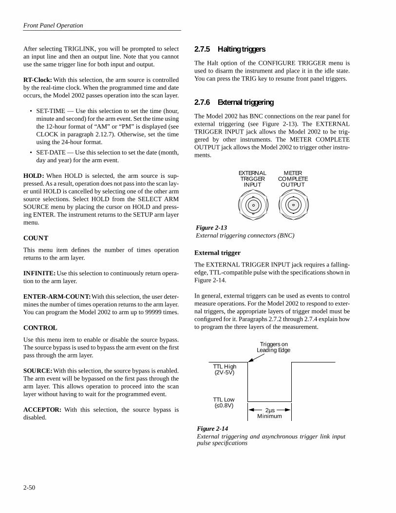
Front Panel Operation
2-50
After selecting TRIGLINK, you will be prompted to selectan input line and then an output line. Note that you cannotuse the same trigger line for both input and output.
RT-Clock: With this selection, the arm source is controlledby the real-time clock. When the programmed time and dateoccurs, the Model 2002 passes operation into the scan layer.
• SET-TIME — Use this selection to set the time (hour,minute and second) for the arm event. Set the time usingthe 12-hour format of “AM” or “PM” is displayed (seeCLOCK in paragraph 2.12.7). Otherwise, set the timeusing the 24-hour format.
• SET-DATE — Use this selection to set the date (month,day and year) for the arm event.
HOLD: When HOLD is selected, the arm source is sup-pressed. As a result, operation does not pass into the scan lay-er until HOLD is cancelled by selecting one of the other armsource selections. Select HOLD from the SELECT ARMSOURCE menu by placing the cursor on HOLD and press-ing ENTER. The instrument returns to the SETUP arm layermenu.
COUNT
This menu item defines the number of times operationreturns to the arm layer.
INFINITE: Use this selection to continuously return opera-tion to the arm layer.
ENTER-ARM-COUNT: With this selection, the user deter-mines the number of times operation returns to the arm layer.You can program the Model 2002 to arm up to 99999 times.
CONTROL
Use this menu item to enable or disable the source bypass.The source bypass is used to bypass the arm event on the firstpass through the arm layer.
SOURCE: With this selection, the source bypass is enabled.The arm event will be bypassed on the first pass through thearm layer. This allows operation to proceed into the scanlayer without having to wait for the programmed event.
ACCEPTOR: With this selection, the source bypass isdisabled.
2.7.5 Halting triggers
The Halt option of the CONFIGURE TRIGGER menu isused to disarm the instrument and place it in the idle state.You can press the TRIG key to resume front panel triggers.
2.7.6 External triggering
The Model 2002 has BNC connections on the rear panel forexternal triggering (see Figure 2-13). The EXTERNALTRIGGER INPUT jack allows the Model 2002 to be trig-gered by other instruments. The METER COMPLETEOUTPUT jack allows the Model 2002 to trigger other instru-ments.
External trigger
The EXTERNAL TRIGGER INPUT jack requires a falling-edge, TTL-compatible pulse with the specifications shown inFigure 2-14.
In general, external triggers can be used as events to controlmeasure operations. For the Model 2002 to respond to exter-nal triggers, the appropriate layers of trigger model must beconfigured for it. Paragraphs 2.7.2 through 2.7.4 explain howto program the three layers of the measurement.
Figure 2-13External triggering connectors (BNC)
EXTERNALTRIGGER
INPUT
METERCOMPLETEOUTPUT
Figure 2-14External triggering and asynchronous trigger link inputpulse specifications
Triggers onLeading Edge
TTL High (2V-5V)
TTL Low (≤0.8V)
2µsMinimum

Front Panel Operation
2-51
Meter complete
The METER COMPLETE OUTPUT jack provides a TTL-compatible output pulse that can be used to trigger otherinstruments. The specifications for this trigger pulse areshown in Figure 2-15.
Typically, you would want the Model 2002 to output a trig-ger after the settling time of each measurement. (Settlingtime includes the internally set measurement settling timeand the user programmed DELAY period.) An output com-pletion pulse occurs after each measurement as long as themeasure source is set to external, timer, manual, or immedi-
Figure 2-15Meter complete and asynchronous trigger link output pulsespecifications
MeterComplete
TTL High (3.4V Typical)
TTL Low (0.25V Typical)
10µsMinimum
ate. See paragraph 2.7.2 for details on programming the mea-sure layer.
The Model 2002 can also output a completion pulse while inthe scan and/or arm layers of operation. Figure 2-12 showswhere these triggers occur in the trigger model. If the scanlayer Source Bypass is enabled (Control = Source) and theScan Source is programmed for External, an output triggeroccurs on each return path through the scan layer. If the armlayer Source Bypass is enabled (Control = Source) and theArm Source is programmed for External, an output triggeroccurs on each return path through the arm layer. See para-graphs 2.7.3 and 2.7.4 for programming the Scan and armlayers.
External triggering example #1
In a typical test system, you may want to close a channel andthen measure the DUT connected to that channel with a mul-timeter. Such a test system is shown in Figure 2-16, whichuses a Model 2002 Multimeter to measure ten DUTsswitched by a Model 7011 multiplexer card in a Model 7001or 7002 Switch System.
The external trigger connections for this test are shown inFigure 2-17. Channel Ready (output) of the Model 7001 or7002 is connected to External Trigger Input of the Model2002. Meter Complete Output of the Model 2002 is con-nected to External Trigger (input) of the Model 7001 or7002.
Figure 2-16DUT test system
NEXT
DISPLAY
PREV
POWER
2002 MULTIMETER
SENSEΩ 4 WIRE
HI
INPUT
LO
INPUTS
CAL
500VPEAK
FR
FRONT/REAR 2A 250V
AMPS
350VPEAK
1100VPEAK
2002 Multimeter
1DUT#1
2DUT#2
10DUT#10
OUTPUT
Card 1
7011 MUX Card
Input HI
Input LO

Front Panel Operation
2-52
.
For this example, the Models 2002 and 7001/7002 are con-figured as follows:
Model 2002:
Idle State:Bench reset = :INIT:CONT ON*
Arm layer:Arm source = Immediate*Arm count = 1*Arm trigger control = Acceptor*
Scan layer:Scan source = Immediate*Scan count = Infinite*Scan trigger control = Acceptor*
Measure layer:Measure source = ExternalMeasure count = Infinite*Measure trigger control = Acceptor*
* Indicates that the setting is the BENCH RESET (and factory) default con-dition.
Model 7001 or 7002:
Idle State:Reset = :INIT:CONT OFF*
Scan List = 1!1-1!10,
Arm layer:Arm spacing = Immediate*Arm count = 1*Arm trigger control = Acceptor*
Scan layer:Scan spacing = Immediate*Number of scans = 1Scan trigger control = Acceptor*
Channel Layer:Channel spacing = ExternalNumber of channels = Use Scanlist length*Channel trigger control = Source*
* Indicates that the setting is the RESET (and factory) default condition.
Notice that the Model 2002 is reset to BENCH defaults. Withthis selection, the multimeter stays armed. Since the armsource and scan source are set to Immediate, the Model 2002waits in the measure layer for a trigger.
With the Channel Trigger Control of the switch system setfor Source, scan operation initially bypasses the need for anexternal trigger to close the first channel. Since arm spacingand scan spacing are set to Immediate, the scan starts as soonas the scanner is taken out of the idle state by pressing theSTEP key. When the front panel STEP key is pressed:
• The scanner arms and closes the first channel.
• After Channel 1!1 settles, a trigger is sent from ChannelReady of the Model 7001/7002 to External TriggerInput of the Model 2002 to trigger a measurement ofDUT #1.
• After the Model 2002 completes the measurement, itoutputs a trigger from Meter Complete Output to Exter-nal Trigger of the Model 7001/7002, which closes thenext channel.
• After Channel 1!2 settles, a trigger is sent to the Model2002 to trigger a measurement of DUT #2.
This process continues until all ten channels are scanned andmeasured.
The data store capability of the Model 2002 could be used tostore the measurements as they occur. Just press the STORE
Figure 2-17External trigger connectors
ChannelReady
ExternalTrigger
7001 or 7002 Switch System
7051-2BNC to BNC
Cables (2)
ExternalTriggerInput
MeterComplete
Output
2002 Multimeter
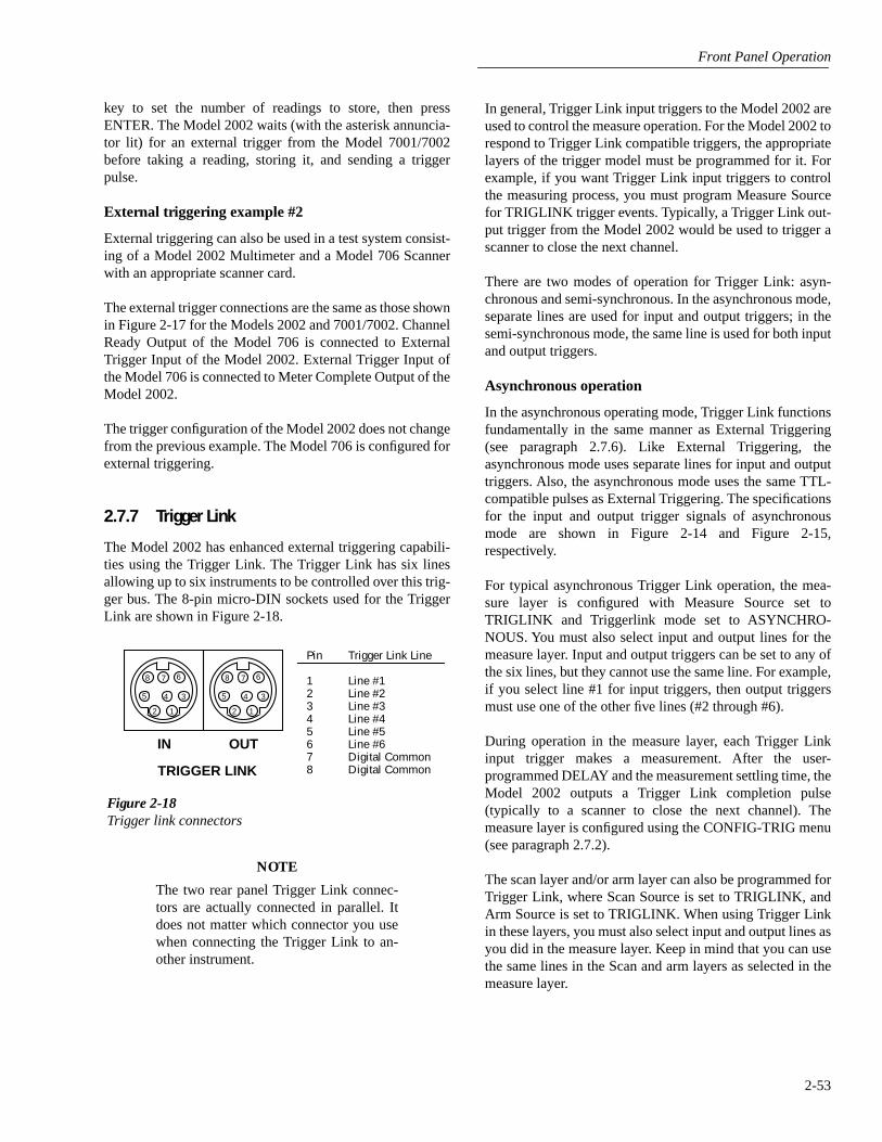
Front Panel Operation
2-53
In general, Trigger Link input triggers to the Model 2002 areused to control the measure operation. For the Model 2002 torespond to Trigger Link compatible triggers, the appropriatelayers of the trigger model must be programmed for it. Forexample, if you want Trigger Link input triggers to controlthe measuring process, you must program Measure Sourcefor TRIGLINK trigger events. Typically, a Trigger Link out-put trigger from the Model 2002 would be used to trigger ascanner to close the next channel.
There are two modes of operation for Trigger Link: asyn-chronous and semi-synchronous. In the asynchronous mode,separate lines are used for input and output triggers; in thesemi-synchronous mode, the same line is used for both inputand output triggers.
Asynchronous operation
In the asynchronous operating mode, Trigger Link functionsfundamentally in the same manner as External Triggering(see paragraph 2.7.6). Like External Triggering, theasynchronous mode uses separate lines for input and outputtriggers. Also, the asynchronous mode uses the same TTL-compatible pulses as External Triggering. The specificationsfor the input and output trigger signals of asynchronousmode are shown in Figure 2-14 and Figure 2-15,respectively.
For typical asynchronous Trigger Link operation, the mea-sure layer is configured with Measure Source set toTRIGLINK and Triggerlink mode set to ASYNCHRO-NOUS. You must also select input and output lines for themeasure layer. Input and output triggers can be set to any ofthe six lines, but they cannot use the same line. For example,if you select line #1 for input triggers, then output triggersmust use one of the other five lines (#2 through #6).
During operation in the measure layer, each Trigger Linkinput trigger makes a measurement. After the user-programmed DELAY and the measurement settling time, theModel 2002 outputs a Trigger Link completion pulse(typically to a scanner to close the next channel). Themeasure layer is configured using the CONFIG-TRIG menu(see paragraph 2.7.2).
The scan layer and/or arm layer can also be programmed forTrigger Link, where Scan Source is set to TRIGLINK, andArm Source is set to TRIGLINK. When using Trigger Linkin these layers, you must also select input and output lines asyou did in the measure layer. Keep in mind that you can usethe same lines in the Scan and arm layers as selected in themeasure layer.
key to set the number of readings to store, then pressENTER. The Model 2002 waits (with the asterisk annuncia-tor lit) for an external trigger from the Model 7001/7002before taking a reading, storing it, and sending a triggerpulse.
External triggering example #2
External triggering can also be used in a test system consist-ing of a Model 2002 Multimeter and a Model 706 Scannerwith an appropriate scanner card.
The external trigger connections are the same as those shownin Figure 2-17 for the Models 2002 and 7001/7002. ChannelReady Output of the Model 706 is connected to ExternalTrigger Input of the Model 2002. External Trigger Input ofthe Model 706 is connected to Meter Complete Output of theModel 2002.
The trigger configuration of the Model 2002 does not changefrom the previous example. The Model 706 is configured forexternal triggering.
2.7.7 Trigger Link
The Model 2002 has enhanced external triggering capabili-ties using the Trigger Link. The Trigger Link has six linesallowing up to six instruments to be controlled over this trig-ger bus. The 8-pin micro-DIN sockets used for the TriggerLink are shown in Figure 2-18.
NOTE
The two rear panel Trigger Link connec-tors are actually connected in parallel. Itdoes not matter which connector you usewhen connecting the Trigger Link to an-other instrument.
TRIGGER LINK
IN OUT
2 1
5 4 3
8 7 6
2 1
5 4 3
8 7 6
Pin Trigger Link Line
1 Line #12 Line #23 Line #34 Line #45 Line #56 Line #67 Digital Common8 Digital Common
Figure 2-18Trigger link connectors

Front Panel Operation
2-54
Asynchronous Trigger Link example #1
In a typical test system, you may want to close a channel andthen measure the DUT connected to the channel with a mul-timeter. Such a test system is shown in Figure 2-19, whichuses a Model 2002 Multimeter to measure ten DUTsswitched by a Model 7011 multiplexer card in a Model 7001/7002 Switch System.
The Trigger Link connections for this test system are shownin Figure 2-20. Trigger Link of the Model 2002 is connectedto Trigger Link of the Model 7001/7002 Switch System.Notice that only one Trigger Link cable is needed.
Figure 2-19DUT test system
2002 Multimeter
1DUT#1
2DUT#2
10DUT#10
OUTPUT
Card 1
7011 MUX Card
Input HI
Input LONEXT
DISPLAY
PREV
POWER
2002 MULTIMETER
SENSEΩ 4 WIRE
HI
INPUT
LO
INPUTS
CAL
500VPEAK
FR
FRONT/REAR 2A 250V
AMPS
350VPEAK
1100VPEAK
Figure 2-20Trigger Link connections (asynchronous example #1)
TriggerLink
7001 or 7002 Switch System
TriggerLink Cable
(8501) 2002 Multimeter
INOUT
TriggerLink
IN OUT
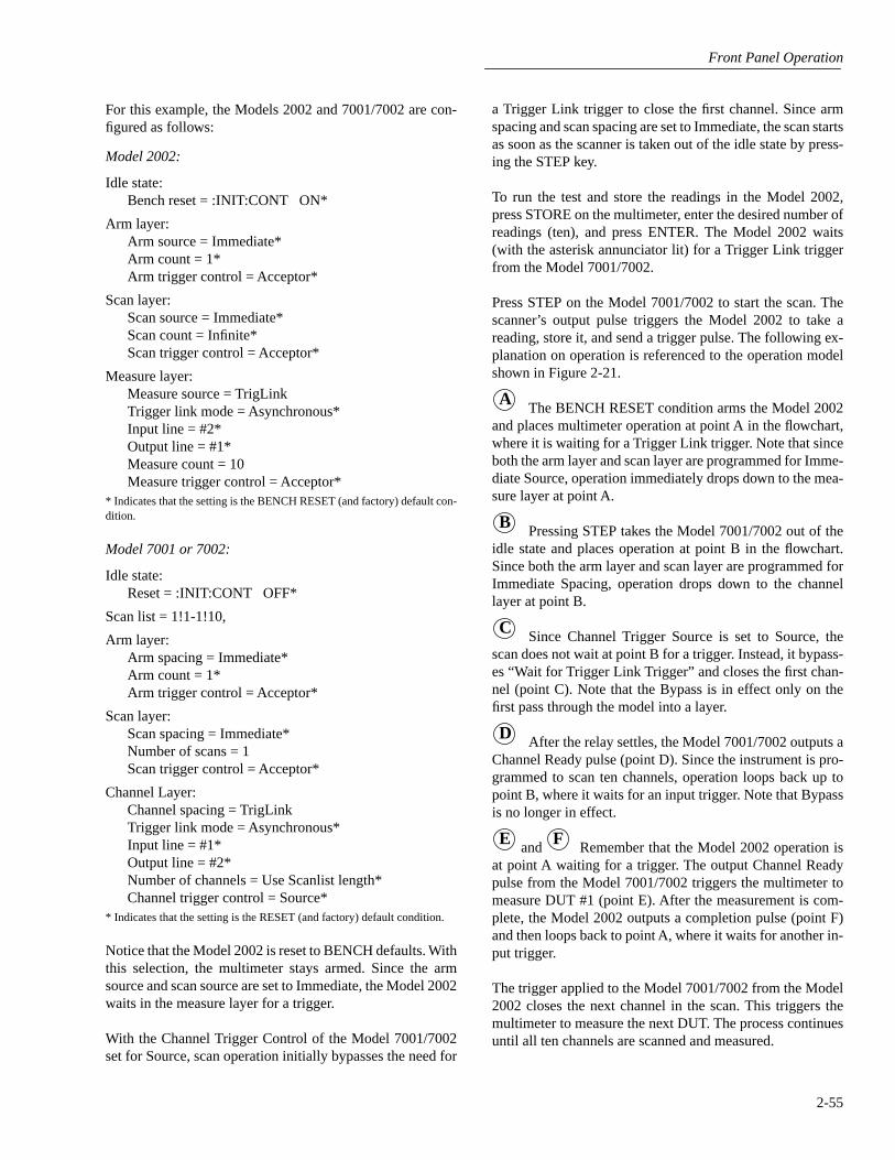
Front Panel Operation
2-55
For this example, the Models 2002 and 7001/7002 are con-figured as follows:
Model 2002:
Idle state:Bench reset = :INIT:CONT ON*
Arm layer:Arm source = Immediate*Arm count = 1*Arm trigger control = Acceptor*
Scan layer:Scan source = Immediate*Scan count = Infinite*Scan trigger control = Acceptor*
Measure layer:Measure source = TrigLinkTrigger link mode = Asynchronous*Input line = #2*Output line = #1*Measure count = 10Measure trigger control = Acceptor*
* Indicates that the setting is the BENCH RESET (and factory) default con-dition.
Model 7001 or 7002:
Idle state:Reset = :INIT:CONT OFF*
Scan list = 1!1-1!10,
Arm layer:Arm spacing = Immediate*Arm count = 1*Arm trigger control = Acceptor*
Scan layer:Scan spacing = Immediate*Number of scans = 1Scan trigger control = Acceptor*
Channel Layer:Channel spacing = TrigLinkTrigger link mode = Asynchronous*Input line = #1*Output line = #2*Number of channels = Use Scanlist length*Channel trigger control = Source*
* Indicates that the setting is the RESET (and factory) default condition.
Notice that the Model 2002 is reset to BENCH defaults. Withthis selection, the multimeter stays armed. Since the armsource and scan source are set to Immediate, the Model 2002waits in the measure layer for a trigger.
With the Channel Trigger Control of the Model 7001/7002set for Source, scan operation initially bypasses the need for
a Trigger Link trigger to close the first channel. Since armspacing and scan spacing are set to Immediate, the scan startsas soon as the scanner is taken out of the idle state by press-ing the STEP key.
To run the test and store the readings in the Model 2002,press STORE on the multimeter, enter the desired number ofreadings (ten), and press ENTER. The Model 2002 waits(with the asterisk annunciator lit) for a Trigger Link triggerfrom the Model 7001/7002.
Press STEP on the Model 7001/7002 to start the scan. Thescanner’s output pulse triggers the Model 2002 to take areading, store it, and send a trigger pulse. The following ex-planation on operation is referenced to the operation modelshown in Figure 2-21.
The BENCH RESET condition arms the Model 2002and places multimeter operation at point A in the flowchart,where it is waiting for a Trigger Link trigger. Note that sinceboth the arm layer and scan layer are programmed for Imme-diate Source, operation immediately drops down to the mea-sure layer at point A.
Pressing STEP takes the Model 7001/7002 out of theidle state and places operation at point B in the flowchart.Since both the arm layer and scan layer are programmed forImmediate Spacing, operation drops down to the channellayer at point B.
Since Channel Trigger Source is set to Source, thescan does not wait at point B for a trigger. Instead, it bypass-es “Wait for Trigger Link Trigger” and closes the first chan-nel (point C). Note that the Bypass is in effect only on thefirst pass through the model into a layer.
After the relay settles, the Model 7001/7002 outputs aChannel Ready pulse (point D). Since the instrument is pro-grammed to scan ten channels, operation loops back up topoint B, where it waits for an input trigger. Note that Bypassis no longer in effect.
and Remember that the Model 2002 operation isat point A waiting for a trigger. The output Channel Readypulse from the Model 7001/7002 triggers the multimeter tomeasure DUT #1 (point E). After the measurement is com-plete, the Model 2002 outputs a completion pulse (point F)and then loops back to point A, where it waits for another in-put trigger.
The trigger applied to the Model 7001/7002 from the Model2002 closes the next channel in the scan. This triggers themultimeter to measure the next DUT. The process continuesuntil all ten channels are scanned and measured.
A
B
C
D
E F
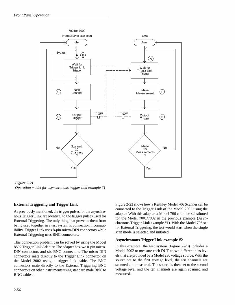
Front Panel Operation
2-56
External Triggering and Trigger Link
As previously mentioned, the trigger pulses for the asynchro-nous Trigger Link are identical to the trigger pulses used forExternal Triggering. The only thing that prevents them frombeing used together in a test system is connection incompat-ibility. Trigger Link uses 8-pin micro-DIN connectors whileExternal Triggering uses BNC connectors.
This connection problem can be solved by using the Model8502 Trigger Link Adapter. The adapter has two 8-pin micro-DIN connectors and six BNC connectors. The micro-DINconnectors mate directly to the Trigger Link connector onthe Model 2002 using a trigger link cable. The BNCconnectors mate directly to the External Triggering BNCconnectors on other instruments using standard male BNC toBNC cables.
Figure 2-22 shows how a Keithley Model 706 Scanner can beconnected to the Trigger Link of the Model 2002 using theadapter. With this adapter, a Model 706 could be substitutedfor the Model 7001/7002 in the previous example (Asyn-chronous Trigger Link example #1). With the Model 706 setfor External Triggering, the test would start when the singlescan mode is selected and initiated.
Asynchronous Trigger Link example #2
In this example, the test system (Figure 2-23) includes aModel 2002 to measure each DUT at two different bias lev-els that are provided by a Model 230 voltage source. With thesource set to the first voltage level, the ten channels arescanned and measured. The source is then set to the secondvoltage level and the ten channels are again scanned andmeasured.
Figure 2-21Operation model for asynchronous trigger link example #1
Idle
BypassB
Wait forTrigger Link
Trigger
ScanChannelC
OutputTrigger
TriggerD
No Scanned10
Channels?
Yes
7001or 7002
MakeMeasurement
Made10
Measurements?
2002Press STEP to start scan
Arm
A
Wait forTrigger Link
Trigger
E
OutputTrigger
TriggerF
No
Yes
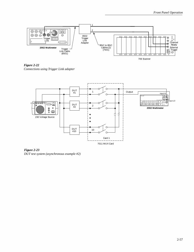
Front Panel Operation
2-57
Figure 2-22Connections using Trigger Link adapter
TriggerLink
2002 Multimeter TriggerLink Cable
(8501)
706 Scanner
IN OUT
BNC to BNCCables (2)
(7501)
1
2
8502Trigger
LinkAdapter Channel
ReadyExternalTrigger
Figure 2-23DUT test system (asynchronous example #2)
NEXT
DISPLAY
PREV
POWER
2002 MULTIMETER
SENSEΩ 4 WIRE
HI
INPUT
LO
INPUTS
CAL
500VPEAK
F R
FRONT/REAR
2A 250V
AMPS
350VPEAK
1100VPEAK
1DUT#1
2DUT#2
10DUT#10
2002 Multimeter
Input HI
Input LO
Output
Card 1
7011 MUX Card
COM OUT
230 Voltage Source
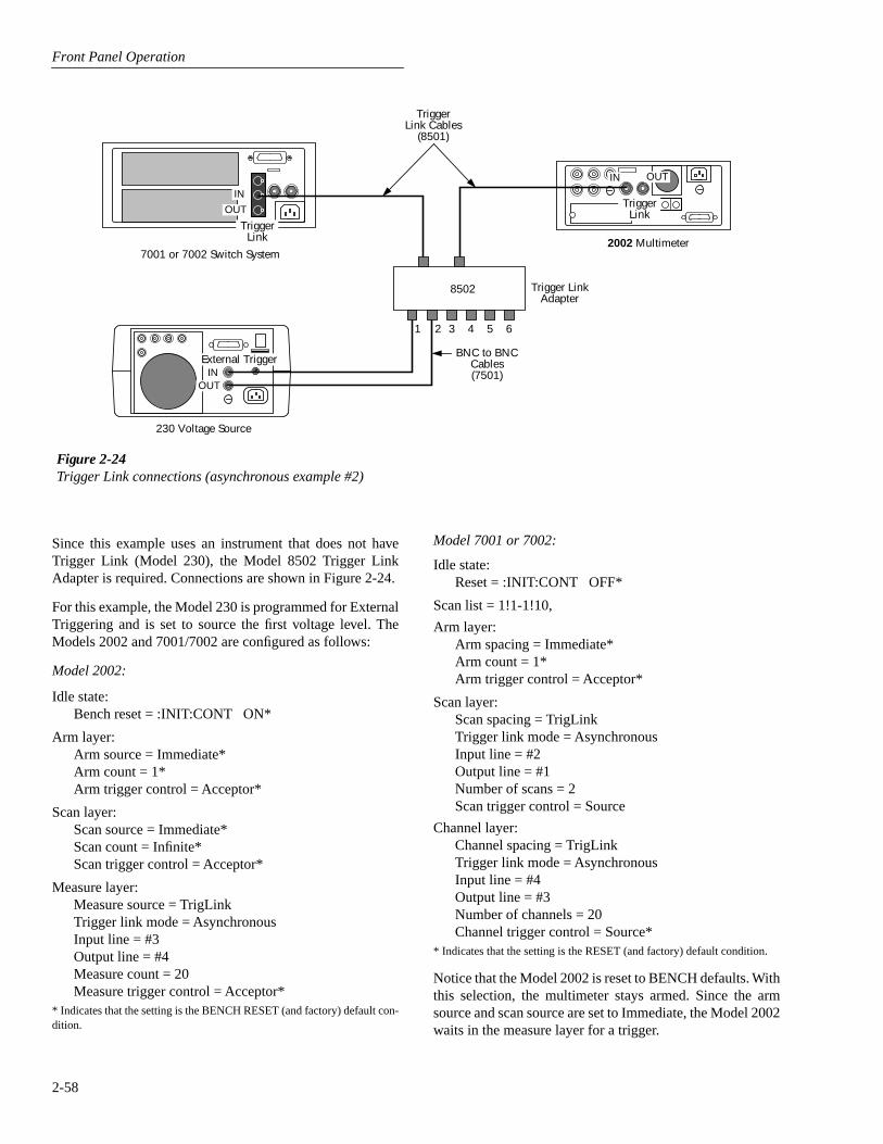
Front Panel Operation
2-58
Since this example uses an instrument that does not haveTrigger Link (Model 230), the Model 8502 Trigger LinkAdapter is required. Connections are shown in Figure 2-24.
For this example, the Model 230 is programmed for ExternalTriggering and is set to source the first voltage level. TheModels 2002 and 7001/7002 are configured as follows:
Model 2002:
Idle state:Bench reset = :INIT:CONT ON*
Arm layer:Arm source = Immediate*Arm count = 1*Arm trigger control = Acceptor*
Scan layer:Scan source = Immediate*Scan count = Infinite*Scan trigger control = Acceptor*
Measure layer:Measure source = TrigLinkTrigger link mode = AsynchronousInput line = #3Output line = #4Measure count = 20Measure trigger control = Acceptor*
* Indicates that the setting is the BENCH RESET (and factory) default con-dition.
Figure 2-24Trigger Link connections (asynchronous example #2)
TriggerLink
7001 or 7002 Switch System
TriggerLink Cables
(8501)
IN
OUT
External TriggerIN
OUT
230 Voltage Source
8502 Trigger LinkAdapter
BNC to BNCCables(7501)
2 3 4
2002 Multimeter
TriggerLink
IN OUT
5 61
Model 7001 or 7002:
Idle state:Reset = :INIT:CONT OFF*
Scan list = 1!1-1!10,
Arm layer:Arm spacing = Immediate*Arm count = 1*Arm trigger control = Acceptor*
Scan layer:Scan spacing = TrigLinkTrigger link mode = AsynchronousInput line = #2Output line = #1Number of scans = 2Scan trigger control = Source
Channel layer:Channel spacing = TrigLinkTrigger link mode = AsynchronousInput line = #4Output line = #3Number of channels = 20Channel trigger control = Source*
* Indicates that the setting is the RESET (and factory) default condition.
Notice that the Model 2002 is reset to BENCH defaults. Withthis selection, the multimeter stays armed. Since the armsource and scan source are set to Immediate, the Model 2002waits in the measure layer for a trigger.
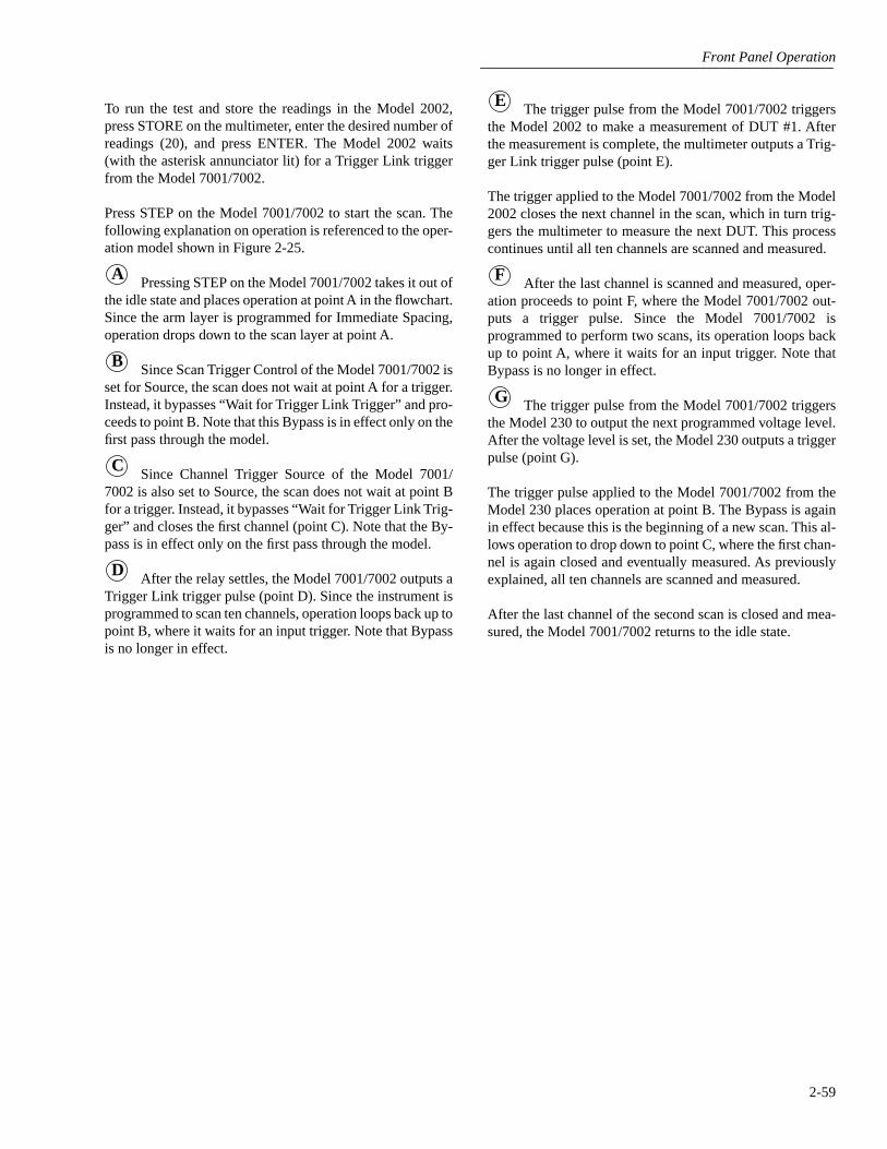
Front Panel Operation
2-59
To run the test and store the readings in the Model 2002,press STORE on the multimeter, enter the desired number ofreadings (20), and press ENTER. The Model 2002 waits(with the asterisk annunciator lit) for a Trigger Link triggerfrom the Model 7001/7002.
Press STEP on the Model 7001/7002 to start the scan. Thefollowing explanation on operation is referenced to the oper-ation model shown in Figure 2-25.
Pressing STEP on the Model 7001/7002 takes it out ofthe idle state and places operation at point A in the flowchart.Since the arm layer is programmed for Immediate Spacing,operation drops down to the scan layer at point A.
Since Scan Trigger Control of the Model 7001/7002 isset for Source, the scan does not wait at point A for a trigger.Instead, it bypasses “Wait for Trigger Link Trigger” and pro-ceeds to point B. Note that this Bypass is in effect only on thefirst pass through the model.
Since Channel Trigger Source of the Model 7001/7002 is also set to Source, the scan does not wait at point Bfor a trigger. Instead, it bypasses “Wait for Trigger Link Trig-ger” and closes the first channel (point C). Note that the By-pass is in effect only on the first pass through the model.
After the relay settles, the Model 7001/7002 outputs aTrigger Link trigger pulse (point D). Since the instrument isprogrammed to scan ten channels, operation loops back up topoint B, where it waits for an input trigger. Note that Bypassis no longer in effect.
A
B
C
D
The trigger pulse from the Model 7001/7002 triggersthe Model 2002 to make a measurement of DUT #1. Afterthe measurement is complete, the multimeter outputs a Trig-ger Link trigger pulse (point E).
The trigger applied to the Model 7001/7002 from the Model2002 closes the next channel in the scan, which in turn trig-gers the multimeter to measure the next DUT. This processcontinues until all ten channels are scanned and measured.
After the last channel is scanned and measured, oper-ation proceeds to point F, where the Model 7001/7002 out-puts a trigger pulse. Since the Model 7001/7002 isprogrammed to perform two scans, its operation loops backup to point A, where it waits for an input trigger. Note thatBypass is no longer in effect.
The trigger pulse from the Model 7001/7002 triggersthe Model 230 to output the next programmed voltage level.After the voltage level is set, the Model 230 outputs a triggerpulse (point G).
The trigger pulse applied to the Model 7001/7002 from theModel 230 places operation at point B. The Bypass is againin effect because this is the beginning of a new scan. This al-lows operation to drop down to point C, where the first chan-nel is again closed and eventually measured. As previouslyexplained, all ten channels are scanned and measured.
After the last channel of the second scan is closed and mea-sured, the Model 7001/7002 returns to the idle state.
E
F
G
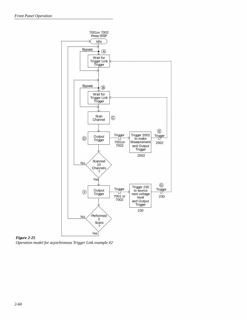
Front Panel Operation
2-60
Figure 2-25Operation model for asynchronous Trigger Link example #2
Idle
Bypass A
Wait forTrigger Link
Trigger
Trigger
C
No Scanned10
Channels?
Yes
ScanChannel
Performed2
Scans?
Wait forTrigger Link
Trigger
D OutputTrigger
Trigger
B
No
Yes
Bypass
F OutputTrigger
Trigger 2002to make
Measurementand Output
Trigger
E
Trigger TriggerTrigger 230to source
next voltagelevel
and OutputTrigger
G
7001or7002
2002
7001 or7002
230
7001or 7002Press STEP
2002
230
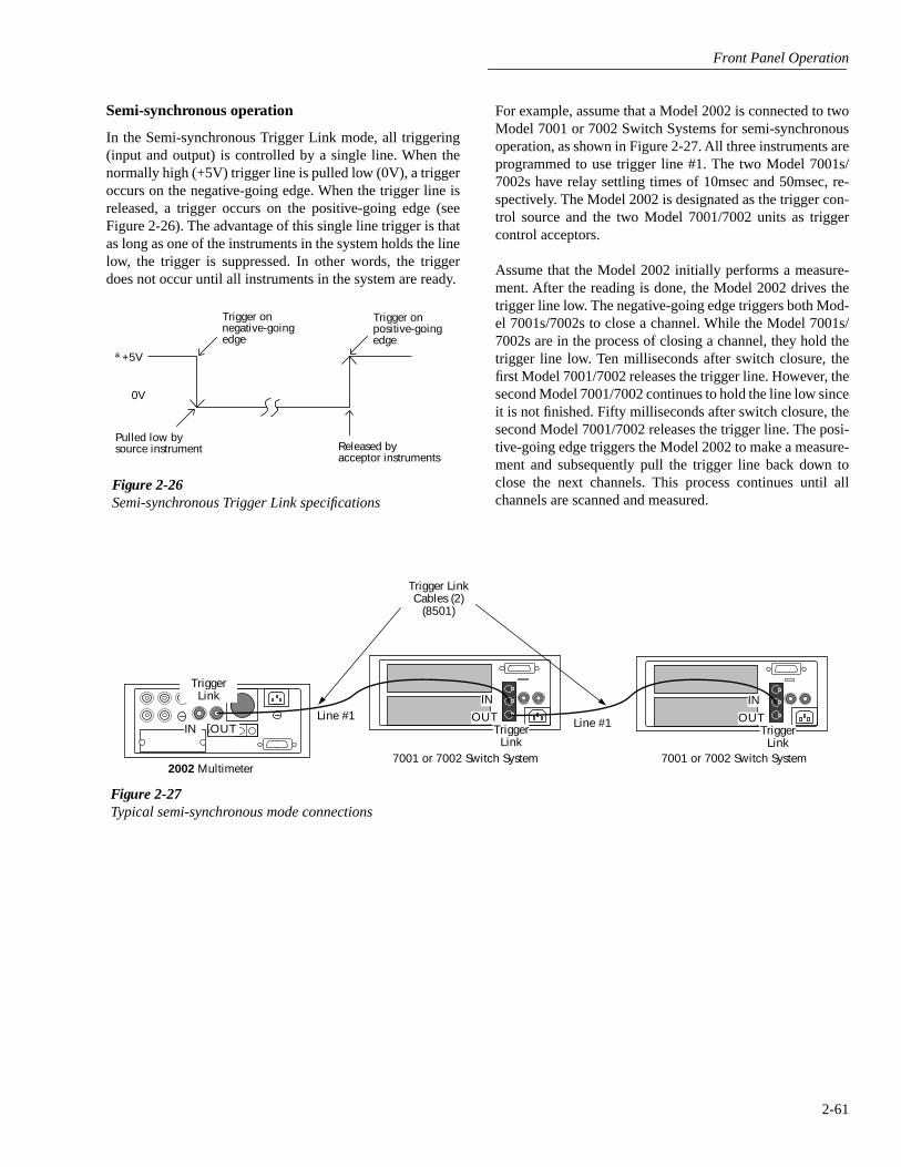
Front Panel Operation
2-61
Semi-synchronous operation
In the Semi-synchronous Trigger Link mode, all triggering(input and output) is controlled by a single line. When thenormally high (+5V) trigger line is pulled low (0V), a triggeroccurs on the negative-going edge. When the trigger line isreleased, a trigger occurs on the positive-going edge (seeFigure 2-26). The advantage of this single line trigger is thatas long as one of the instruments in the system holds the linelow, the trigger is suppressed. In other words, the triggerdoes not occur until all instruments in the system are ready.
Figure 2-26Semi-synchronous Trigger Link specifications
ª +5V
Trigger onnegative-goingedge
Trigger onpositive-goingedge
Pulled low bysource instrument Released by
acceptor instruments
0V
For example, assume that a Model 2002 is connected to twoModel 7001 or 7002 Switch Systems for semi-synchronousoperation, as shown in Figure 2-27. All three instruments areprogrammed to use trigger line #1. The two Model 7001s/7002s have relay settling times of 10msec and 50msec, re-spectively. The Model 2002 is designated as the trigger con-trol source and the two Model 7001/7002 units as triggercontrol acceptors.
Assume that the Model 2002 initially performs a measure-ment. After the reading is done, the Model 2002 drives thetrigger line low. The negative-going edge triggers both Mod-el 7001s/7002s to close a channel. While the Model 7001s/7002s are in the process of closing a channel, they hold thetrigger line low. Ten milliseconds after switch closure, thefirst Model 7001/7002 releases the trigger line. However, thesecond Model 7001/7002 continues to hold the line low sinceit is not finished. Fifty milliseconds after switch closure, thesecond Model 7001/7002 releases the trigger line. The posi-tive-going edge triggers the Model 2002 to make a measure-ment and subsequently pull the trigger line back down toclose the next channels. This process continues until allchannels are scanned and measured.
Figure 2-27Typical semi-synchronous mode connections
TriggerLink
IN
OUTTrigger
Link7001 or 7002 Switch System
Trigger LinkCables (2)
(8501)
2002 Multimeter
IN
OUT
TriggerLink
IN OUT Line #1Line #1
7001 or 7002 Switch System

Front Panel Operation
2-62
Semi-synchronous Trigger Link example
This example uses the same test system (Figure 2-19) thatwas used for the Asynchronous Trigger Link example #1.However, triggering is done using the Semi-synchronousmode. Trigger Link connections are shown in Figure 2-28.
The two instruments are configured as follows:
Model 2002:
Idle state:Bench reset = :INIT:CONT ON*
Arm layer:Arm source = Immediate*Arm count = 1*Arm trigger control = Acceptor*
Scan layer:Scan source = Immediate*Scan count = Infinite*Scan trigger control = Acceptor*
Measure layer:Measure source = TrigLinkTrigger link mode = Semi-synchronousSemi-sync line = #1*Measure count = 10Measure trigger control = Acceptor*
* Indicates that the setting is the BENCH RESET (and factory) defaultcondition.
Model 7001 or 7002:
Idle state:Reset = :INIT:CONT OFF*
Scan list = 1!1-1!10,
Arm layer:Arm spacing = Immediate*Arm count = 1*Arm trigger control = Acceptor*
Scan layer:Scan spacing = Immediate*Number of scans = 1Scan trigger control = Acceptor*
Channel layer:Channel spacing = TrigLinkTrigger link mode = Semi-synchronousSemi-sync line = #1Number of channels = Use Scanlist length*Channel trigger control = Source*
* Indicates that the setting is the RESET (and factory) default condition.
To run the test and store the readings in the Model 2002,press STORE on the multimeter, enter the desired number ofreadings (ten), and press ENTER. The Model 2002 waits(with the asterisk annunciator lit) for a Trigger Link triggerfrom the Model 7001/7002. Press STEP on the Model 7001/7002 to start the scan.
The following explanation on operation is referenced to theoperation model shown in Figure 2-29.
Figure 2-28Trigger Link connections (semi-synchronous example)
2002 Multimeter
TriggerLink
IN OUT
TriggerLink
7001 or 7002 Switch System Trigger LinkCable (8501)
INOUT
Line #1
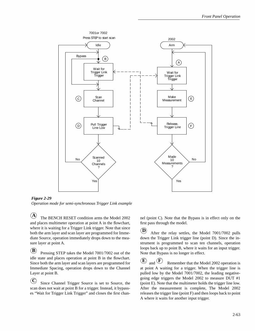
Front Panel Operation
2-63
The BENCH RESET condition arms the Model 2002and places multimeter operation at point A in the flowchart,where it is waiting for a Trigger Link trigger. Note that sinceboth the arm layer and scan layer are programmed for Imme-diate Source, operation immediately drops down to the mea-sure layer at point A.
Pressing STEP takes the Model 7001/7002 out of theidle state and places operation at point B in the flowchart.Since both the arm layer and scan layers are programmed forImmediate Spacing, operation drops down to the ChannelLayer at point B.
Since Channel Trigger Source is set to Source, thescan does not wait at point B for a trigger. Instead, it bypass-es “Wait for Trigger Link Trigger” and closes the first chan-
Figure 2-29Operation mode for semi-synchronous Trigger Link example
Idle
BypassB
Wait forTrigger Link
Trigger
ScanChannelC
Pull TriggerLine LowD
No Scanned10
Channels?
Yes
7001or 7002
MakeMeasurement
Made10
Measurements?
2002Press STEP to start scan
Arm
A
Wait forTrigger Link
Trigger
E
Release,Trigger Line F
No
Yes
A
B
C
nel (point C). Note that the Bypass is in effect only on thefirst pass through the model.
After the relay settles, the Model 7001/7002 pullsdown the Trigger Link trigger line (point D). Since the in-strument is programmed to scan ten channels, operationloops back up to point B, where it waits for an input trigger.Note that Bypass is no longer in effect.
and Remember that the Model 2002 operation isat point A waiting for a trigger. When the trigger line ispulled low by the Model 7001/7002, the leading negative-going edge triggers the Model 2002 to measure DUT #1(point E). Note that the multimeter holds the trigger line low.After the measurement is complete, The Model 2002releases the trigger line (point F) and then loops back to pointA where it waits for another input trigger.
D
E F
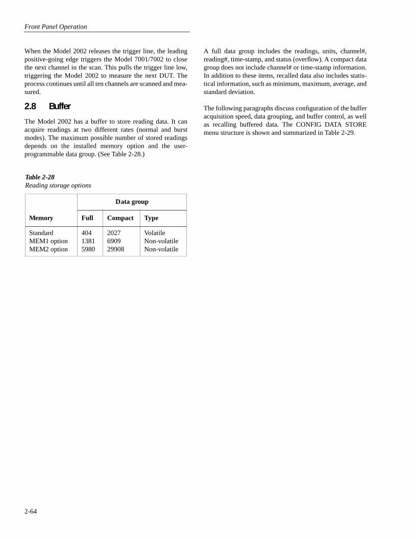
Front Panel Operation
2-64
A full data group includes the readings, units, channel#,reading#, time-stamp, and status (overflow). A compact datagroup does not include channel# or time-stamp information.In addition to these items, recalled data also includes statis-tical information, such as minimum, maximum, average, andstandard deviation.
The following paragraphs discuss configuration of the bufferacquisition speed, data grouping, and buffer control, as wellas recalling buffered data. The CONFIG DATA STOREmenu structure is shown and summarized in Table 2-29.
When the Model 2002 releases the trigger line, the leadingpositive-going edge triggers the Model 7001/7002 to closethe next channel in the scan. This pulls the trigger line low,triggering the Model 2002 to measure the next DUT. Theprocess continues until all ten channels are scanned and mea-sured.
2.8 Buffer
The Model 2002 has a buffer to store reading data. It canacquire readings at two different rates (normal and burstmodes). The maximum possible number of stored readingsdepends on the installed memory option and the user-programmable data group. (See Table 2-28.)
Table 2-28Reading storage options
Data group
Memory Full Compact Type
Standard MEM1 optionMEM2 option
40413815980
2027690929908
VolatileNon-volatileNon-volatile

Front Panel Operation
2-65
2.8.1 Burst mode
The burst data acquisition mode maximizes the reading rateof the Model 2002. Burst mode consists of two distinct phas-es:
• Acquiring raw readings (A/D counts).
• Post-processing the raw readings by applying calibra-tion constants and storing the resulting readings in thebuffer.
In burst mode, the Model 2002 acquires 4.5-digit readings at2000 readings/second. The post-processing takes about2msec/reading. If any filter or math operations are enabled,the post-processing time is longer. To make this reading ratepossible, certain tradeoffs are made with the unit’s function-ality, as described in the following paragraph.
Configuring the unit for burst mode
Before burst mode can be enabled, the following changesmust be made to the present instrument configuration:
• Select a valid measurement function for the burst mode,as listed in Table 2-30.
• Select a fixed range for the expected signal, or chooseautorange to let the instrument select a fixed range whenburst mode starts.
• Set the trigger event source in the measure layer toimmediate, external, trigger link, or timer.
• Disable any “multiple displays”.
• Disable scanning.
Table 2-29CONFIGURE DATA STORE menu structure
Menu item Description
Burst-modeData-group
FullCompact
ControlFill-and-stopPretrigger
PercentageReading-countEvent
ContinuousNever
TimestampType
Relative-TimeReal-Time
FormatAbsoluteDelta
Clear-allCount
Enter-countUse-trigger-model
FeedAfter-calcBefore-calcNone
Acquire 4.5-digit readings at 2000 readings/sec and store in buffer.Select data types to store in buffer.
Store reading, units, channel#, reading#, time-stamp, and status (overflow).Store reading, units, reading#, and status (overflow).
Select type of buffer control.Fill buffer with readings and stop.Wait for pretrigger event; store before and after readings.
Enter percentage of stored readings before trigger.Enter count of stored readings before trigger.Select source for pretrigger event.
Store readings in buffer continuously.Readings are not stored.
Configure timestamp:Check or change type:
Reference timestamp to relative time.Reference timestamp to real-time.
Select timestamp format:Reference each timestamp to the first buffer reading (relative), or to the time and date (real).Reference each timestamp to the previous buffer reading.
Clear all stored readings and buffer statistics.Select buffer size.
Enter number of readings to store.Use (finite) measure count from trigger model.
Select type of reading to store.Store readings after math calculation.Store readings before math calculation.No readings are placed in the buffer.
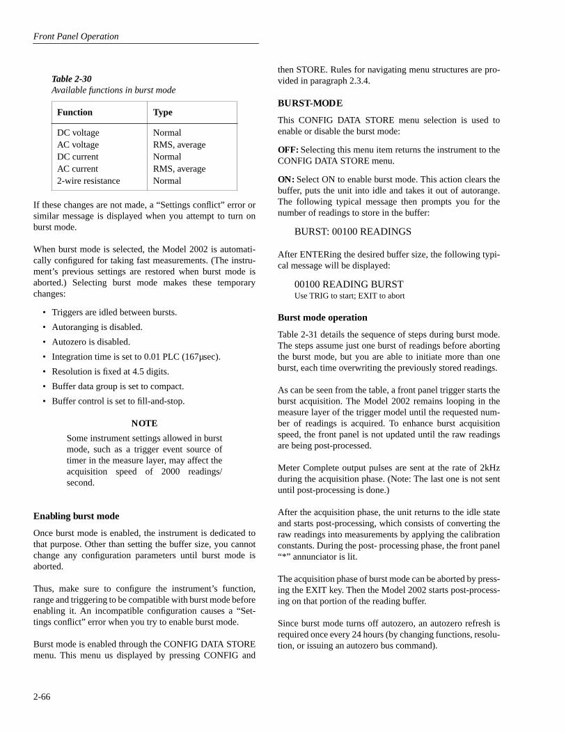
Front Panel Operation
2-66
If these changes are not made, a “Settings conflict” error orsimilar message is displayed when you attempt to turn onburst mode.
When burst mode is selected, the Model 2002 is automati-cally configured for taking fast measurements. (The instru-ment’s previous settings are restored when burst mode isaborted.) Selecting burst mode makes these temporarychanges:
• Triggers are idled between bursts.
• Autoranging is disabled.
• Autozero is disabled.
• Integration time is set to 0.01 PLC (167µsec).
• Resolution is fixed at 4.5 digits.
• Buffer data group is set to compact.
• Buffer control is set to fill-and-stop.
NOTE
Some instrument settings allowed in burstmode, such as a trigger event source oftimer in the measure layer, may affect theacquisition speed of 2000 readings/second.
Enabling burst mode
Once burst mode is enabled, the instrument is dedicated tothat purpose. Other than setting the buffer size, you cannotchange any configuration parameters until burst mode isaborted.
Thus, make sure to configure the instrument’s function,range and triggering to be compatible with burst mode beforeenabling it. An incompatible configuration causes a “Set-tings conflict” error when you try to enable burst mode.
Burst mode is enabled through the CONFIG DATA STOREmenu. This menu us displayed by pressing CONFIG and
Table 2-30Available functions in burst mode
Function Type
DC voltage AC voltage DC current AC current 2-wire resistance
NormalRMS, averageNormalRMS, averageNormal
then STORE. Rules for navigating menu structures are pro-vided in paragraph 2.3.4.
BURST-MODE
This CONFIG DATA STORE menu selection is used toenable or disable the burst mode:
OFF: Selecting this menu item returns the instrument to theCONFIG DATA STORE menu.
ON: Select ON to enable burst mode. This action clears thebuffer, puts the unit into idle and takes it out of autorange.The following typical message then prompts you for thenumber of readings to store in the buffer:
BURST: 00100 READINGS
After ENTERing the desired buffer size, the following typi-cal message will be displayed:
00100 READING BURSTUse TRIG to start; EXIT to abort
Burst mode operation
Table 2-31 details the sequence of steps during burst mode.The steps assume just one burst of readings before abortingthe burst mode, but you are able to initiate more than oneburst, each time overwriting the previously stored readings.
As can be seen from the table, a front panel trigger starts theburst acquisition. The Model 2002 remains looping in themeasure layer of the trigger model until the requested num-ber of readings is acquired. To enhance burst acquisitionspeed, the front panel is not updated until the raw readingsare being post-processed.
Meter Complete output pulses are sent at the rate of 2kHzduring the acquisition phase. (Note: The last one is not sentuntil post-processing is done.)
After the acquisition phase, the unit returns to the idle stateand starts post-processing, which consists of converting theraw readings into measurements by applying the calibrationconstants. During the post- processing phase, the front panel“*” annunciator is lit.
The acquisition phase of burst mode can be aborted by press-ing the EXIT key. Then the Model 2002 starts post-process-ing on that portion of the reading buffer.
Since burst mode turns off autozero, an autozero refresh isrequired once every 24 hours (by changing functions, resolu-tion, or issuing an autozero bus command).

Front Panel Operation
2-67
2.8.2 Configuring data storage
The data storage configuration menu is used for the follow-ing operations:
• To acquire a burst of readings at high speed.
• To select the data types stored in the buffer.
• To select the buffer control.
• To clear the buffer of readings and statistics.
• To specify the number of readings to store.
• To specify the source of readings to be stored.
The buffer is configured from the CONFIG DATA STOREmenu (see Table 2-29). This menu is displayed by pressing
Table 2-31Burst mode sequence
Action Result Annunciators
BURST MODE ON ENTER
ENTER
TRIG
RECALL
EXIT
EXIT
BURST:00100 READINGSUse , , , , ENTER, EXIT, or INFO00100 READING BURSTUse TRIG to start; EXIT to abort(burst readings acquired)
(post-processing of readings)BURST:00100 READINGSProcessing rdg #xx of 1000
BURST:00100 READINGSStorage complete; press RECALL
BURST:00100 READINGSUse , , , , ENTER, EXIT, or INFORdg#+00000...Rdg#+00099BURST:00100 READINGSUse , , , , ENTER, EXIT, or INFO
(press ENTER to loop back to start)BURST MODE ABORTEDUse CONFIG → STORE to resume
(normal reading display)
ARM and AUTO off
ARM on
* on
ARM and * off
ARM and AUTO on
Notes:1. This table assumes the unit was set for autorange before enabling burst.2. Multiple displays of buffered readings are available when burst data is recalled. (See paragraph 2.5.4.)
CONFIG and then STORE. Rules for navigating menu struc-tures are provided in paragraph 2.3.4.
BURST-MODE
The burst mode is discussed in paragraph 2.8.1.
DATA-GROUP
This menu selection chooses the data items that are stored inthe buffer. Note that changing the data grouping clears thebuffer.
FULL: With this selection, for each reading, the followinginformation is stored: units, channel number (if applicable),reading number, time-stamp, and status (overflow).
Front Panel Operation
2-68
CLEAR-ALL
This action can be used at any time to clear the data buffer ofall stored readings and buffer statistics. Since the MEM1 andMEM2 memory options are non-volatile, clear-all is the onlyway for the operator to clear the reading buffer.
TIMESTAMP
When using FULL data grouping (see DATA-GROUP), atimestamp is included with each buffer reading. This menuselection is used to check and/or change the timestamp typeand format.
TYPE: This menu item is used to check and/or change thetimestamp type. Note that changing the timestamp typeclears the buffer.
• RELATIVE-TIME — With this selection, timestampsare oriented to a timer with the first buffer readingtimestamped at 0.000000 seconds. Each followingtimestamp is then based on the currently selected for-mat (see FORMAT). With the ABSOLUTE formatselected, the timestamp for each reading is referenced(in seconds) to the first buffer reading. With the DELTAformat selected, each timestamp is referenced (in sec-onds) to the previous timestamp.
• REAL-TIME — With this selection, timestamps areoriented to the real-time clock and are based on the cur-rently selected format (see FORMAT). With the ABSO-LUTE format selected, each reading is simplytimestamped with the actual time and date. Time can beexpressed in the 12-hour (AM, PM) format or the 24-hour format (see CLOCK in paragraph 2.12.7).
With the DELTA format selected, the first buffer read-ing is timestamped at 00000d 00h 00m 00.00s (zerodays, hours, minutes and seconds). Each subsequenttimestamp is referenced (in days, hours, minutes andseconds) to the previous timestamp.
Timestamp type for buffer readings is coupled to timestamptype for bus readings. Thus, if you change timestamp typefrom this menu structure, it also changes in the MAINMENU structure (see TIMESTAMP in paragraph 2.12.7).
FORMAT: This menu item is used to check and/or changethe timestamp format. Note that if format is changed afterreadings are stored in the buffer, the timestamps will changeto reflect the alternate format.
• ABSOLUTE — With this selection, each timestampprovides the time and date that the reading was taken(see REAL-TIME timestamp type), or the number ofseconds from the first buffer reading that the readingwas taken (see RELATIVE-TIME timestamp type).
The “full” data group should be used for 6.5 digits or greaterresolution. It also allows you to change function, range, orchannel while storing.
COMPACT: With this selection, readings, units, readingnumbers, and status (overflow) are stored. This allows morereadings to be stored in the buffer.
“Compact” is only accurate and displayed to 5.5 digits. Itdoes not allow changes of function, range, or channel whilestoring.
CONTROL
This menu item controls the type of data storage.
FILL-AND-STOP: This control selection fills the bufferwith the requested number of readings and stops. You canthen recall the readings.
PRETRIGGER: This selection continuously stores read-ings until a user-programmed trigger event occurs. It thenstores post-trigger readings. For example, with a buffer sizeof 100 readings, there will be 50 readings stored before thetrigger event and 50 readings stored after the trigger.
The first reading after the trigger is reading zero. Pretriggerreadings have reading numbers and relative time-stampswith a minus sign; post-trigger readings have reading num-bers and relative time-stamps with a plus sign.
After selecting PRETRIGGER, configure pretrigger controlfurther as follows:
• PERCENTAGE or READING-COUNT — Specify thenumber of readings to store before the trigger event as apercentage of the total number of stored readings, or asa number of pretrigger readings. You will be promptedto enter the percentage or count value.
• EVENT — Selects the source of the pretrigger or“mark-point” event. This can be a Manual, GPIB, Trig-ger Link or External trigger.
CONTINUOUS: With this control selection, readings arealways stored in the buffer. The process continues, with theoldest readings being overwritten in a circular manner, untilstorage is interrupted with the EXIT key.
NEVER: Gets set to this if data storage has been interrupted.Pressing the STORE key changes NEVER to FILL-AND-STOP.

Front Panel Operation
2-69
• DELTA — With this selection, each timestamp is refer-enced to the timestamp for the previous reading. Thisprovides the time between buffer readings. Timestampsare provided in days, hours, minutes and seconds (seeREAL-TIME timestamp type) or in seconds (see REL-ATIVE-TIME timestamp type).
COUNT
With this menu selection, you specify the number of read-ings to store.
ENTER-COUNT: This item allows you to specify the buff-er size in number of readings.
USE-TRIGGER-MODEL: This selection lets you defaultto the measure count in the present trigger configuration, aslong as the measure count is a finite value.
FEED
This selection allows you to select the source of readings tobe placed in the buffer.
AFTER-CALC: With this item, readings are stored in thebuffer after any enabled math operations are performed.
BEFORE-CALC: With this item selected, readings areplaced in the buffer before any math is performed.
NONE: With NONE selected, no readings are placed in thebuffer when storage is performed. Pressing the STORE keychanges NONE to the AFTER-CALC selection.
2.8.3 Storing and recalling readings
Tables 2-32 through 2-34 detail the sequence of steps for thevarious modes of buffer control. The tables assume the bufferis configured as explained in paragraph 2.8.2.
Note that during data storage, the reading number on the bot-tom line of the display is one ahead of the reading on the topline.
There are “multiple displays” available when recalling buff-ered readings. These are explained in paragraph 2.8.4.
Table 2-32Fill-and-stop sequence
Action Result Annunciator
STOREENTER
RECALL
EXIT
STORE 00100 READINGSStoring reading #xx of 100Storage complete; press RECALLRdg#+00000 @Time=+000.000000 sec...Rdg#+00099 @Time=+002.700473 sec(normal reading display)
(* on)(* off)

Front Panel Operation
2-70
2.8.4 Buffer multiple displays
Math operations performed on buffered readings are avail-able when readings are recalled. Just press NEXT DISPLAYto view the math operation on the bottom line of front paneldisplay, in the following order:
1. MAX maximum reading in buffer, for example:
MAX=+1.635968e+00 at RDG# +00090
Notes:
A. Display response may be slow due to calculation ofstatistics for large buffers.
Table 2-33Continuous sequence
Action Result Annunciator
STOREENTER
RECALL
EXITRECALL
EXITEXIT
STORE 00100 READINGSStoring reading #xx of 100100 rdgs stored; continuous ONRdg#+00000 @Time=+003.903546 sec...100 rdgs stored; continuous ONRdg#+00000 @Time=+067.709331 sec...100 rdgs stored; continuous ONSTORAGE INTERRUPTEDAcquired 100 of 100 readings
(normal reading display)
(* on)
(* off)
Table 2-34Pretrigger sequence
Action Result Annunciator
STOREENTERTRIG
RECALL
EXIT
STORE 00100 READINGSWaiting for pretrigger event Storing reading #xx of 50Storage complete; press RECALL Rdg#-00050 @Time=-004.999990 sec...Rdg#+00000 @Time=+000.000000 sec...Rdg#+00049 @Time=+004.899996 sec(normal reading display)
(* on)
(* off)
Note: A manual trigger is used as an example. Other pretrigger events include GPIB, trigger link, and external.
B. Exponents are in terms of primary units of functionon top line (i.e., volts, not millivolts).
2. MIN minimum reading in buffer, for example:
MIN=+1.627611e+00 at RDG# +00012
3. AVG This math operation displays the mean value ofthe buffered readings, for example:
AVG=+1.6345e+00

Front Panel Operation
2-71
The equation used to calculate the mean is:
where: xi is a stored reading, and
n is the number of stored readings.
Note: If n = 0, the result is NAN (not a number).
4. SDEV This operation displays the standard deviationof the stored readings, for example:
SDEV=1.4944e-03
The equation used to calculate the standard deviation is:
where: xi is a stored reading, and
n is the number of stored readings.
Note: If n ≤ 1, the result is NAN (not a number).
NOTE
These statistics are invalid if the measure-ment function changed during data store(e.g., when scanning different functions).
The Model 2002 uses IEEE-754 floatingpoint format for math calculations.
The last display in this series allows you to dump the buff-ered readings to a printer. See paragraph 2.12.2 for details onconfiguring printers.
2.9 Filter
Filtering stabilizes noisy measurements. The Model 2002uses a digital filter, which is based on reading conversions.The displayed, stored, or transmitted reading is simply an av-erage of a number of reading conversions.
When a filter is enabled, the selected filter configuration forthat measurement function is in effect. Filtering is enabled
by pressing the FILTER key (FILT annunciator turns on).Pressing FILTER a second time disables the filter.
Filtering is performed only on primary display measure-ments; it has no effect on multiple displays.
2.9.1 Filter types
The Model 2002 has two types of digital filters: averagingand advanced. Both types are a simple average of one to 100reading conversions. The difference between them is theuser-programmable noise “window” of the advanced filter.
The noise window, which is expressed as a percentage ofrange (0-100%), allows a faster response time to large signalstep changes (e.g., scanned readings). A reading conversionoutside the plus or minus noise window fills the filter “stack”immediately.
If the noise does not exceed the selected percentage of range,the reading is based on an average of reading conversions. Inthis case, the advanced filter works the same as the averagingfilter. If the noise does exceed the selected percentage, thereading is a single reading conversion, and new averagingstarts from this point. The two filter types are compared inFigure 2-30.
2.9.2 Filter modes
An additional filter parameter is the mode, either moving orrepeating. A moving filter is a first-in, first-out stack, wherethe newest reading conversion replaces the oldest. An aver-age of the stacked reading conversions yields a reading.Therefore, after a selected number of conversions, a movingfilter gives a new reading for every new conversion.
A repeating filter takes a selected number of reading conver-sions, averages them, and yields a reading. It then flushes itsstack and starts over. This characteristic is useful when scan-ning channels.
If burst mode is enabled with filtering, the post-processingtime increases. A filter mode setting of repeating is ignoredin burst mode.
Filter modes are compared in Figure 2-31.
y
Xii 1=
n
∑n
---------------=
Xi2-
1n--- Xi
i=1
n
∑
2
i=1
n
∑n-1
-----------------------------------------------y =
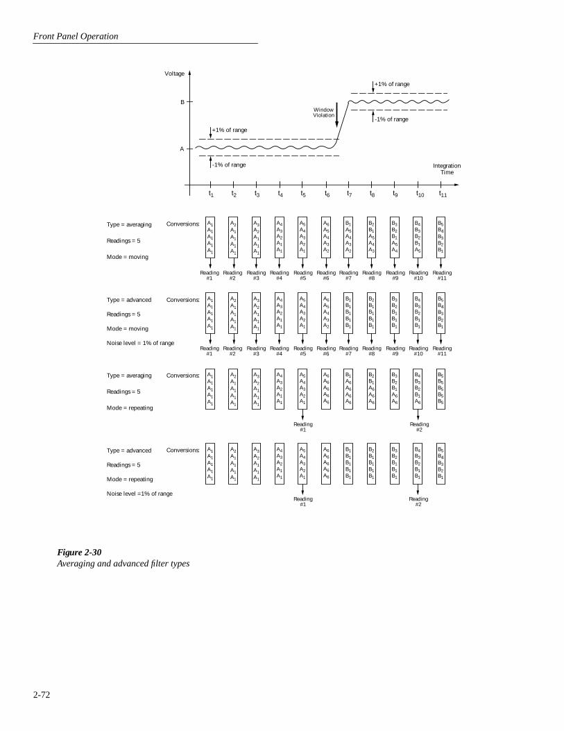
Front Panel Operation
2-72
Figure 2-30
Averaging and advanced filter types
A
B
t1 t2 t3 t4 t5 t6 t7 t8 t9 t10
+1% of range
-1% of range IntegrationTime
+1% of range
-1% of range
A1A1A1A1A1
A2A1A1A1A1
A3A2A1A1A1
A4A3A2A1A1
A5A4A3A2A1
B1A5A4A3A2
B2B1A5A4A3
B3B2B1A5A4
B4B3B2B1A5
B5B4B3B2B1
Conversions:
Reading#6
Type = averaging
Readings = 5
Mode = moving
Reading#5
Reading#4
Reading#3
Reading#2
Reading#1
A5A4A3A2A1
B1A6A6A6A6
B2B1A6A6A6
B3B2B1A6A6
B4B3B2B1A6
B5B5B5B5B5
Conversions:Type = averaging
Readings = 5
Mode = repeating
Reading#2
Reading#1
A1A1A1A1A1
A2A1A1A1A1
A3A2A1A1A1
A4A3A2A1A1
A6A6A6A6A6
Conversions:Type = advanced
Readings = 5
Mode = moving
Noise level = 1% of range
A1A1A1A1A1
A2A1A1A1A1
A3A2A1A1A1
A4A3A2A1A1
A5A4A3A2A1
B1B1B1B1B1
B2B1B1B1B1
B3B2B1B1B1
B4B3B2B1B1
B5B4B3B2B1
Reading#6
Reading#5
Reading#4
Reading#3
Reading#2
Reading#1
A6A5A4A3A2
Reading#11
Reading#10
Reading#9
Reading#8
Reading#7
Conversions:
Reading#2
Reading#1
Type = advanced
Readings = 5
Mode = repeating
Noise level =1% of range
Voltage
A6A5A4A3A2
t11
Reading#11
Reading#10
Reading#9
Reading#8
Reading#7
WindowViolation
A5A4A3A2A1
A1A1A1A1A1
A2A1A1A1A1
A3A2A1A1A1
A4A3A2A1A1
A6A6A6A6A6
B1B1B1B1B1
B2B1B1B1B1
B3B2B1B1B1
B4B3B2B1B1
B5B4B3B2B1

Front Panel Operation
2-73
2.9.3 Response time
The various filter parameters have the following effects onthe time needed to display, store, or output a filtered reading:
• Filter type: The time to the first reading is the same forboth types, but thereafter averaging mode yields a fasterreading than repeating mode. Also, advanced has afaster response to changes in the input signal thanaveraging.
• Number of reading conversions: Speed and accuracyare tradeoffs.
Conversion #10 #9
#8#7#6#5#4#3#2
Conversion #1
Reading#1
A. Type - Average, Readings = 10, Mode - Moving
Conversion #11 #10
#9#8#7#6#5#4#3
Conversion #2
Reading#2
Conversion #12 #11
#10#9
#8#7#6#5#4
Conversion #3
Reading#3
Conversion #10 #9
#8#7#6#5#4#3#2
Conversion #1
Reading#1
B. Type - Average, Readings = 10, Mode - Repeating
Conversion #20 #19
#18#17#16#15#14#13#12
Conversion #11
Reading#2
Conversion #30 #29
#28#27
#26#25#24#23#22
Conversion #21
Reading#3
Figure 2-31
Moving and repeating filter modes
• Noise window: For the advanced type, a tradeoff ofspeed, accuracy, and response to input signal changes.
2.9.4 Auto filtering
For those measurement functions with a filter, one of the pos-sible selections is automatic filtering. Depending on the mea-surement function and type, the AUTO selection may disablefiltering. Auto filtering is summarized in Table 2-35.
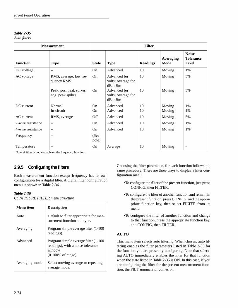
Front Panel Operation
2-74
2.9.5 Configuring the filters
Each measurement function except frequency has its ownconfiguration for a digital filter. A digital filter configurationmenu is shown in Table 2-36.
Table 2-35
Auto filters
Measurement Filter
Function Type State Type ReadingsAveraging Mode
Noise ToleranceLevel
DC voltage -- On Advanced 10 Moving 1%
AC voltage RMS, average, low fre-quency RMS
Peak, pos. peak spikes, neg. peak spikes
Off
On
Advanced for volts; Average for dB, dBmAdvanced for volts; Average for dB, dBm
10
10
Moving
Moving
5%
5%
DC current Normal In-circuit
OnOn
AdvancedAdvanced
10 10
MovingMoving
1%1%
AC current RMS, average Off Advanced 10 Moving 5%
2-wire resistance -- On Advanced 10 Moving 1%
4-wire resistance -- On Advanced 10 Moving 1%
Frequency -- (See note)
Temperature -- On Average 10 Moving -
Note: A filter is not available on the frequency function.
Table 2-36
CONFIGURE FILTER menu structure
Menu item Description
Auto Default to filter appropriate for mea-surement function and type.
Averaging Program simple average filter (1-100 readings).
Advanced Program simple average filter (1-100 readings), with a noise tolerance window(0-100% of range).
Averaging-mode Select moving average or repeating average mode.
Choosing the filter parameters for each function follows thesame procedure. There are three ways to display a filter con-figuration menu:
•To configure the filter of the present function, just pressCONFIG, then FILTER.
•To configure the filter of another function and remain inthe present function, press CONFIG, and the appro-priate function key, then select FILTER from itsmenu.
•To configure the filter of another function and changeto that function, press the appropriate function key,and CONFIG, then FILTER.
AUTO
This menu item selects auto filtering. When chosen, auto fil-tering enables the filter parameters listed in Table 2-35 forthe function you are presently configuring. Note that select-ing AUTO immediately enables the filter for that functionwhen the state listed in Table 2-35 is ON. In this case, if youare configuring the filter for the present measurement func-tion, the FILT annunciator comes on.

Front Panel Operation
2-75
• Math performed on buffered readings (maximum andminimum values, average, and standard deviation).
• Math performed on single readings as a part of a pass/fail limits test.
• Math performed on scanned readings (ratio and delta).
The first category is configured from the CONFIGUREMATH menu and is described in this paragraph. Math oper-ations on buffered readings are available in multiple displaysof recalled data and are discussed in paragraph 2.8. Limittests are described in paragraph 2.12, under main menu op-erations. Ratio and delta calculations on scanned channelsare available from the CONFIGURE SCAN menu, as dis-cussed in paragraph 2.11.
Note that once enabled for a function, the polynomial and thepercentage calculations are in effect across function changes.
NOTE
The Model 2002 uses IEEE-754 floatingpoint format for math calculations.
2.10.1 Polynomial
This math operation allows you to mathematically manipu-late normal display readings (X) according to the followingpolynomial calculation:
Y = (a2)X
2
+ (a1)X + (a0)
where: X is the normal display reading
a2, a1 and a0 are user entered constants
Y is the displayed result
The value of the “a2”, “a1” and “a0” constants can bechanged through the CONFIGURE MATH menu (see para-graph 2.10.4). The before and after calculation can be viewedwith one of the multiple displays, as described in paragraph2.10.5. When necessary, the resulting Y value is displayed inscientific notation.
The polynomial can be used in place of the more familiarmX+b slope calculation. Simply let a2=0, a1=m and a0=b.Over the bus, the mX+b calculation still exists and is coupledto the polynomial calculation. Thus, changing a1 and/or a0changes m and/or b respectively. See paragraph 3.11 fordetails.
AVERAGING
Use this selection for a non-windowed averaging filter. Amessage indicating the presently set number of reading con-versions to average (the “stack” size) is displayed. If youchange the filter value, be sure to press ENTER.
Note that the number of reading conversions selected for theaveraging filter type is also coupled to that for the advancedfilter type.
ADVANCED
This selection is for an averaging filter with a noise window.(It is not available with dB or dBm units, ratio or delta, tem-perature or frequency.) A message indicating the presentlyset number of reading conversions to average (the “stack”size) is displayed.
You can retain the present filter value or you can key in an-other value. In either case, press ENTER to display the max-imum noise window.
The displayed level is the plus or minus percentage of rangewindow around the first reading conversion in the stack. Besure to press ENTER if you key in a different percentage.
Note that the number of reading conversions (filter value) se-lected for the advanced filter is also coupled to that for theaveraging filter.
AVERAGING-MODE
This selection determines the mode of a digital filter for ameasurement function, either a moving or repeating average.
MOVING:
This item selects a moving filter, where a newreading conversion is shifted into a stack as the oldest con-version is shifted out (FIFO). When the stack is full, a simpleaverage is taken to yield a reading.
REPEAT:
This menu item selects a repeating filter, where anaverage of a selected number of reading conversions is takenfor each reading.
2.10 Math
Model 2002 math operations are divided into four catego-ries:
• Math performed on single readings (polynomial per-cent, and percent deviation).

Front Panel Operation
2-76
2.10.2 Percent
This operation lets you specify a target reading value. Thedisplayed reading will be expressed as a percentage of thetarget value, often in scientific notation. The percentage cal-culation is performed as follows:
As an example, consider the default target value for percent-age calculations, where:
Therefore, on the 200µA range, a 100µA input would be0.01% of the target value and a typical reading would be dis-played as follows:
+1.0000e+04µAAC%
Range: 200 µAAC Coupling: AC
Note that the value is not 10000%, but 10000µ%, whichequals 0.01%. With the calculate multiple display selected,as described in paragraph 3.10.5, the display would be:
+1.0000e+04µAAC%
Reading = +100.000
where the bottom line shows the reading (in the units andmultiplier prefix of the top line) before the percentage calcu-lation is performed.
2.10.3 Percent deviation
The following math calculation provides the percent devia-tion between the normal display reading and the currentlystored REL value for the selected function:
where: X is the normal display reading
Y is the REL value for the selected function
PD is the displayed result (percent deviation)
Percent Deviation is enabled through the CONFIGUREMATH menu (see paragraph 2.10.4).
Note that Percent Deviation does not scale based on the m, k,or M range factor. For example, 10% deviation on the 20k
Ω
range will be displayed as 10.00000. If the number is toolarge for the allowed number of leading zeroes (for example10 on the 2k
Ω
range), the display will switch to 7-1/2 digitscientific notation.
2.10.4 Selecting and configuring math
The polynomial, percent or percent deviation calculation isselected and configured from the CONFIGURE MATHmenu (see Table 2-37). The selected calculation is enabledby pressing the MATH key. The Model 2002 then displaysthe result of the calculation, using scientific notation wherenecessary. Pressing MATH a second time disables thecalculation.
NONE
With this menu item, no math operation goes into effectwhen the MATH key is pressed. The MATH annunciatorlights, but NONE is displayed on the top line.
POLYNOMIAL
This menu item selects the polynomial calculation andallows you to program the polynomial constants. The “a2”constant is displayed first. You can retain the displayed valueor key in a new value. In either case, press ENTER to displaythe “a1” constant. Retain or change this constant and pressENTER to display the “a0” constant. If you change the “a0”constant, be sure to again press ENTER.
PERCENT
This menu item selects the percent calculation and lets youspecify the target value. If you key in a new target value, besure to press ENTER.
PERCENT DEVIATION
This menu item selects the percent deviation calculation andreturns the display to the normal measurement state.
PercentInput ReadingTarget Value----------------------------------x 100=
100% = +1.000000e+00
PDX-Y( )Y
---------------x 100%=
Table 2-37
CONFIGURE MATH menu structure
Menu item Description
None Select no calculation when MATH key is pressed.
Polynomial Select polynomial calculation and enter constants.
Percent Select percent calculation and enter target (reference) value.
Percent deviation Select percent deviation calculation.

Front Panel Operation
2-77
When using these cards, the Model 2002 can:
• Close and open individual channels.
• Scan through channels using a separate measurementfunction for each channel, if desired.
• Perform ratio and delta measurements using two user-defined channels.
Using external scanner cards
When using external scanning, you can define separate mea-surement functions for a maximum of 80 channels. Notehowever, that you cannot close or open external channelsusing Model 2002 controls. Use the switching mainframecontrols to open and close individual channels.
In order to synchronize Model 2002 measurements withexternal channel closure, connect the Model 2002 externaltrigger inputs or the trigger link to the external switchingmainframe trigger inputs and outputs. Refer to paragraphs2.7.6 and 2.7.7 for examples on using external triggering andthe trigger link.
2.11.2 Front panel scanner controls
Controls that affect scanner card operation include:
• CHAN: Allows you to open and close internal scannercard channels.
• CONFIGURE CHAN: Defines the measurement func-tions for each internal and external scanner card chan-nel, selects the number of external channels, defineschannels assigned to the internal scan list, and saves/restores an alternate measurement function.
• CONFIGURE SCAN: Selects internal or external scan-ning and controls ratio/delta operation when using theinternal scanner.
• SCAN: Starts/stops scanning using the selected scanlist. Configures scan count, scan interval, and enablesbuffer storage and recall if internal or external list isselected.
• EXIT: Disables scanning and returns to normaloperation. (Trigger model is restored to pre-scanningconfiguration.)
• and : Allows you to manually scan through chan-nels.
• PREV/NEXT DISPLAY: Allows you to display the twoadjacent channels (manual scanning only).
2.10.5 Calculate multiple display
One of the multiple displays lets you view the reading on thebottom line of the display and the result of the calculation onthe top line. This display is available by repeatedly pressingeither the NEXT or PREVious DISPLAY key to scrollthrough the multiple displays for the particular function. Thefollowing is a typical message for a percentage calculation:
-7.0431e+01 VDC %
Reading = -0.704311
The display resolution on the bottom line follows that chosenfor the top line. If scientific notation is required on the topline, it is fixed at 4.5 digits. The value on the bottom linetracks the units and prefix of the top line. (For example, if thetop line displays µA, then the units on the bottom line areµA.)
Note that this multiple display is not available on the fre-quency function.
2.11 Scanning
The Model 2002 can be used with an internal scanner card(Model 2001-SCAN or 2001-TCSCAN) or with externalscanner cards installed in switching mainframes such as theModels 706, 7001 and 7002. The following paragraphs dis-cuss various aspects of using scanning with the Model 2002.
2.11.1 Scanning overview
A scanner allows you to switch among a number of input sig-nals to the Model 2002 for measurement. The channel con-trol and scanning capabilities depend on whether an internalor external scanner card is being used, as well as on the capa-bilities of the scanner card in question. Refer to the docu-mentation supplied with the scanner card for specificconnection information.
Using an internal scanner card
The optional Model 2001-SCAN scanner card allows you toswitch or scan up to ten 2-pole channels, or five 4-pole chan-nels. Two of the channels use solid-state switching for high-speed multiplexing, ratio, or delta applications.
The optional Model 2001-TCSCAN Thermocouple/GeneralPurpose Scanner Card allows you to multiplex one of nine 2-pole, or one of four 4-pole analog signals into the Model2002, and/or any combination of 2- or 4-pole analog signals.Refer to the instruction manual for the Model 2001-TCS-CAN for complete operation information.

Front Panel Operation
2-78
2.11.3 Using CHAN key to close and open internal channels
The CHAN key controls channels on the internal scannercard only. The CHAN key allows you to directly:
• Close a specific channel (or channel pair for 4-wirefunctions).
• Immediately open any internal closed channel (or chan-nel pair for 4-wire functions).
Channel selection menu
Table 2-38 summarizes the channel selection menu structurealong with a brief description of each item. More detaileddescriptions of these menu items are presented in the follow-ing paragraphs. See paragraph 2.3.4 for general rules on nav-igating menus.
With a scanner card installed in the option slot of the Model2002, the following options are available when CHAN ispressed:
CLOSE-CHANNEL:
This menu item prompts you to enterthe channel (from 1 to 10) that you wish to close. Use thecursor keys ( and ) and the RANGE
and
keys todisplay the channel and press ENTER. The number of theclosed channel will be displayed on the front panel alongwith normal readings.
Selecting a different channel from the one that is presentlyclosed will cause the closed channel to open and allow a set-tling time before closing the selected channel.
Channel relays will be closed according to the presentlyselected function. If a 2-wire function is used, only the relayfor that one channel will be closed. If a 4-wire function isselected, both the selected channel relay and the matchingrelay pair will close. For example, closing channel 2 will alsoclose the channel 7 relay. Fixed 4-pole relay pairs are:
• 1 and 6 (not available for Model 2001-TCSCAN)
• 2 and 7
• 3 and 8
• 4 and 8
• 5 and 10.
OPEN-ALL-CHANNELS:
Selecting OPEN-ALL-CHAN-NELS will immediately open any closed scanner card chan-nels or channel pair for 4-wire functions.
Table 2-38
CHANNEL SELECTION menu structure
Menu item Description
CLOSE-CHANNELENTER CHAN#01 (1-10)
OPEN-ALL-CHANNELS
Close channel menu:Use cursor, range, and ENTER keys.
Press ENTER to open closed channel(s).
Note: This menu is only available with a scanner card installed.
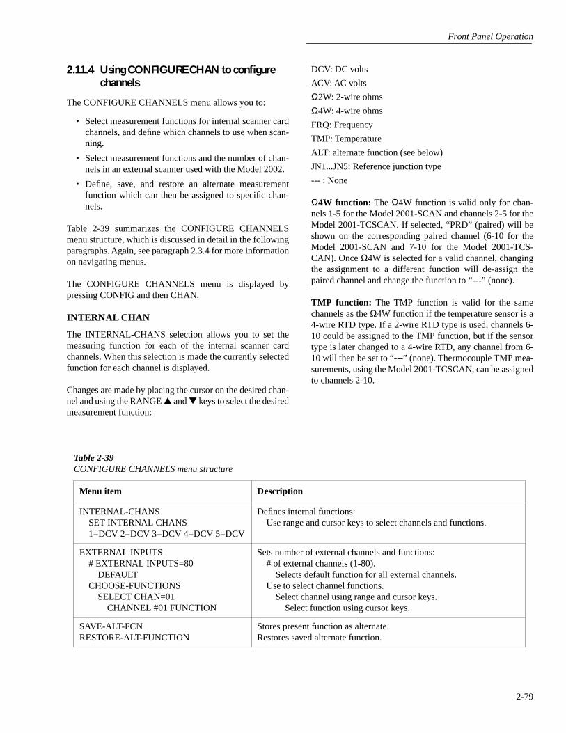
Front Panel Operation
2-79
2.11.4 Using CONFIGURE CHAN to configure channels
The CONFIGURE CHANNELS menu allows you to:
• Select measurement functions for internal scanner cardchannels, and define which channels to use when scan-ning.
• Select measurement functions and the number of chan-nels in an external scanner used with the Model 2002.
• Define, save, and restore an alternate measurementfunction which can then be assigned to specific chan-nels.
Table 2-39 summarizes the CONFIGURE CHANNELSmenu structure, which is discussed in detail in the followingparagraphs. Again, see paragraph 2.3.4 for more informationon navigating menus.
The CONFIGURE CHANNELS menu is displayed bypressing CONFIG and then CHAN.
INTERNAL CHAN
The INTERNAL-CHANS selection allows you to set themeasuring function for each of the internal scanner cardchannels. When this selection is made the currently selectedfunction for each channel is displayed.
Changes are made by placing the cursor on the desired chan-nel and using the RANGE
and
keys to select the desiredmeasurement function:
DCV: DC volts
ACV: AC volts
Ω
2W: 2-wire ohms
Ω
4W: 4-wire ohms
FRQ: Frequency
TMP: Temperature
ALT: alternate function (see below)
JN1...JN5: Reference junction type
--- : None
Ω
4W function:
The
Ω
4W function is valid only for chan-nels 1-5 for the Model 2001-SCAN and channels 2-5 for theModel 2001-TCSCAN. If selected, “PRD” (paired) will beshown on the corresponding paired channel (6-10 for theModel 2001-SCAN and 7-10 for the Model 2001-TCS-CAN). Once
Ω
4W is selected for a valid channel, changingthe assignment to a different function will de-assign thepaired channel and change the function to “---” (none).
TMP function:
The TMP function is valid for the samechannels as the
Ω
4W function if the temperature sensor is a4-wire RTD type. If a 2-wire RTD type is used, channels 6-10 could be assigned to the TMP function, but if the sensortype is later changed to a 4-wire RTD, any channel from 6-10 will then be set to “---” (none). Thermocouple TMP mea-surements, using the Model 2001-TCSCAN, can be assignedto channels 2-10.
Table 2-39
CONFIGURE CHANNELS menu structure
Menu item Description
INTERNAL-CHANSSET INTERNAL CHANS1=DCV 2=DCV 3=DCV 4=DCV 5=DCV
Defines internal functions:Use range and cursor keys to select channels and functions.
EXTERNAL INPUTS# EXTERNAL INPUTS=80
DEFAULTCHOOSE-FUNCTIONS
SELECT CHAN=01CHANNEL #01 FUNCTION
Sets number of external channels and functions:# of external channels (1-80).
Selects default function for all external channels.Use to select channel functions.
Select channel using range and cursor keys.Select function using cursor keys.
SAVE-ALT-FCNRESTORE-ALT-FUNCTION
Stores present function as alternate.Restores saved alternate function.
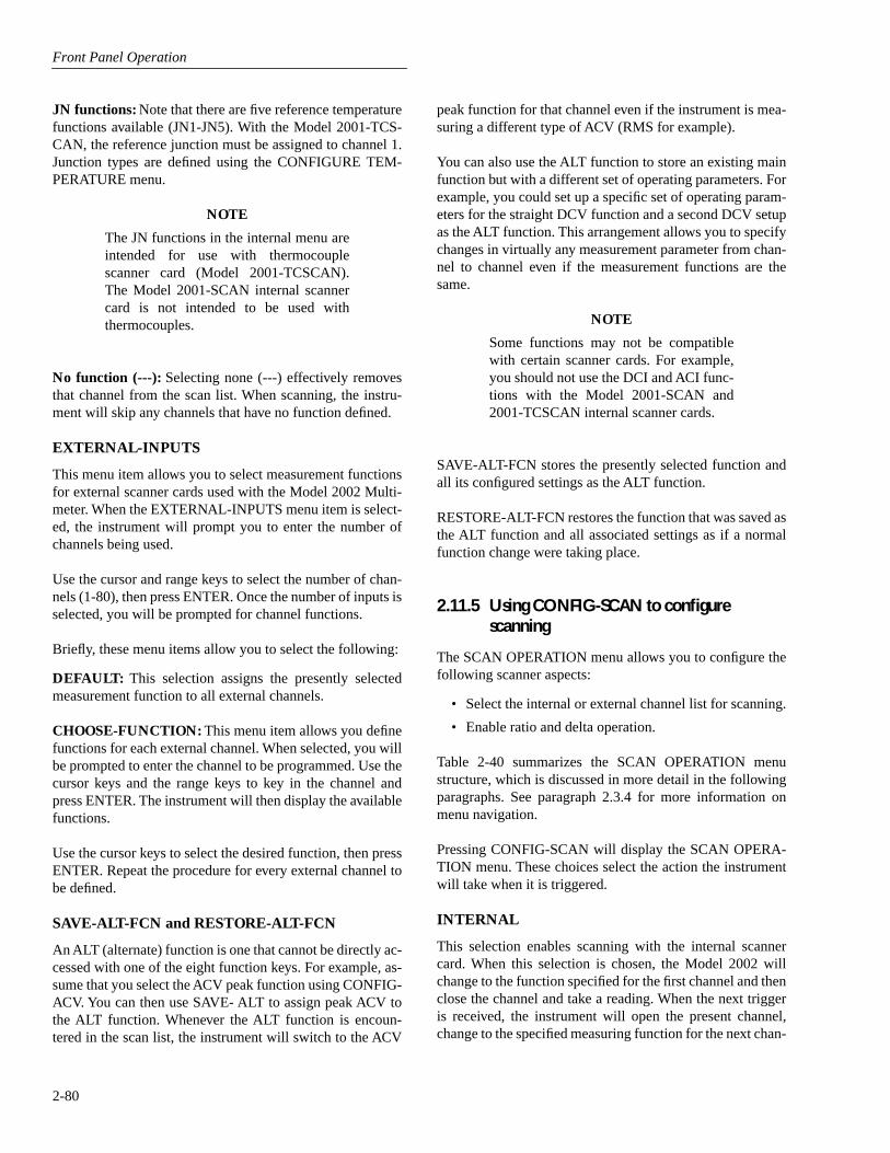
Front Panel Operation
2-80
JN functions:
Note that there are five reference temperaturefunctions available (JN1-JN5). With the Model 2001-TCS-CAN, the reference junction must be assigned to channel 1.Junction types are defined using the CONFIGURE TEM-PERATURE menu.
NOTE
The JN functions in the internal menu areintended for use with thermocouplescanner card (Model 2001-TCSCAN).The Model 2001-SCAN internal scannercard is not intended to be used withthermocouples.
No function (---):
Selecting none (---) effectively removesthat channel from the scan list. When scanning, the instru-ment will skip any channels that have no function defined.
EXTERNAL-INPUTS
This menu item allows you to select measurement functionsfor external scanner cards used with the Model 2002 Multi-meter. When the EXTERNAL-INPUTS menu item is select-ed, the instrument will prompt you to enter the number ofchannels being used.
Use the cursor and range keys to select the number of chan-nels (1-80), then press ENTER. Once the number of inputs isselected, you will be prompted for channel functions.
Briefly, these menu items allow you to select the following:
DEFAULT:
This selection assigns the presently selectedmeasurement function to all external channels.
CHOOSE-FUNCTION:
This menu item allows you definefunctions for each external channel. When selected, you willbe prompted to enter the channel to be programmed. Use thecursor keys and the range keys to key in the channel andpress ENTER. The instrument will then display the availablefunctions.
Use the cursor keys to select the desired function, then pressENTER. Repeat the procedure for every external channel tobe defined.
SAVE-ALT-FCN and RESTORE-ALT-FCN
An ALT (alternate) function is one that cannot be directly ac-cessed with one of the eight function keys. For example, as-sume that you select the ACV peak function using CONFIG-ACV. You can then use SAVE- ALT to assign peak ACV tothe ALT function. Whenever the ALT function is encoun-tered in the scan list, the instrument will switch to the ACV
peak function for that channel even if the instrument is mea-suring a different type of ACV (RMS for example).
You can also use the ALT function to store an existing mainfunction but with a different set of operating parameters. Forexample, you could set up a specific set of operating param-eters for the straight DCV function and a second DCV setupas the ALT function. This arrangement allows you to specifychanges in virtually any measurement parameter from chan-nel to channel even if the measurement functions are thesame.
NOTE
Some functions may not be compatiblewith certain scanner cards. For example,you should not use the DCI and ACI func-tions with the Model 2001-SCAN and2001-TCSCAN internal scanner cards.
SAVE-ALT-FCN stores the presently selected function andall its configured settings as the ALT function.
RESTORE-ALT-FCN restores the function that was saved asthe ALT function and all associated settings as if a normalfunction change were taking place.
2.11.5 Using CONFIG-SCAN to configure scanning
The SCAN OPERATION menu allows you to configure thefollowing scanner aspects:
• Select the internal or external channel list for scanning.
• Enable ratio and delta operation.
Table 2-40 summarizes the SCAN OPERATION menustructure, which is discussed in more detail in the followingparagraphs. See paragraph 2.3.4 for more information onmenu navigation.
Pressing CONFIG-SCAN will display the SCAN OPERA-TION menu. These choices select the action the instrumentwill take when it is triggered.
INTERNAL
This selection enables scanning with the internal scannercard. When this selection is chosen, the Model 2002 willchange to the function specified for the first channel and thenclose the channel and take a reading. When the next triggeris received, the instrument will open the present channel,change to the specified measuring function for the next chan-

Front Panel Operation
2-81
nel, and then close the channel and take a reading. The pro-cess repeats until all channels in the list are scanned.
The instrument defaults to this selection if it detects a scan-ner card on power-up.
EXTERNAL
This menu selection enables scanning with an external scan-ner card located in a switching mainframe. This selectionoperates in a manner similar to INTERNAL except that theinternal scanner is not used. When this menu item is selected,the instrument will immediately change to the selected mea-suring function for the first channel. When the multimeter istriggered, it will take a measurement and then change to themeasurement function for the next channel. This processrepeats until all channels in the scan list are scanned.
The instrument defaults to this selection if it does not detecta scanner card on power-up.
RATIO and DELTA
Either of these two selections configures the Model 2002 tomeasure the two specified internal scanner channels and thencompute the ratio or difference (delta) between them. When
Table 2-40
SCAN OPERATION menu structure
Menu item Description
INTERNAL Enables internal scanning.
EXTERNAL Enables external scanning.
RATIOMEASUREREFERENCEFUNCTION
Enables ratio mode (internal).Selects measure channel.Selects reference channel.Selects ratio function.
DELTAMEASUREREFERENCEFUNCTION
Enables delta mode (inter-nal).
Selects measure channel.Selects reference channel.Selects delta function.
RATIO or DELTA is selected, the instrument will close thescanner reference channel and then wait for a trigger. Whenthe reading is triggered, the unit will make a measurement onthe reference channel, switch to the measurement channel,and then take a second measurement. After measuring themeasurement channel, the unit will compute and display theratio or delta value, and switch back to the reference channelto wait for the next trigger. Note that the ratio mode uses 7-1/2 digits of display resolution, but the channel number willnot be displayed.
The following options are available for RATIO and DELTA:
MEASURE:
This option is used to select the measure chan-nel. After selecting MEASURE, place the cursor on thedesired channel and press ENTER.
REFERENCE:
This option is used to select the measurechannel. After selecting REFERENCE, place the cursor onthe desired channel and press ENTER.
FUNCTION:
This option is used to select the function.After selecting FUNCTION, place the cursor on the desiredfunction (DCV,
Ω
2 or
Ω
4) and press ENTER.
Ratio and Delta computation:
During configuration, onechannel is defined as the reference channel, and a secondchannel is defined as the measurement channel. Ratio anddelta are computed from signals measured on these channelsas follows:
2.11.6 Using SCAN to configure scan parameters
Once an internal or external scan list is enabled, you use theSCAN key to configure internal or external scanning. Themenu structure of Figure 2-32 shows the procedure.
The procedure changes scan layer parameters in the triggermodel. When scanning is disabled by the EXIT key, the trig-ger model is restored to its pre-scanning configuration.
Ratio MeasureReference------------------------=
Delta = Measure - Reference
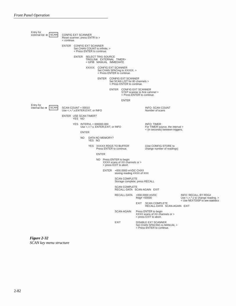
Front Panel Operation
2-82
SCAN CONFIG EXT SCANNERReset scanner; press ENTR to >< continue.
ENTER CONFIG EXT SCANNERSet CHAN COUNT to infinite; >< Press ENTER to continue.
ENTER SELECT TRIG SOURCETRIGLINK EXTERNAL TIMER>< GPIB MANUAL IMMEDIATE
XXXXX CONFIG EXT SCANNERSet CHAN SPACing to XXXXX. >< Press ENTER to continue.
ENTER CONFIG EXT SCANNERSet SCAN LIST for 80 channels >< Press ENTER to continue.
ENTER CONFIG EXT SCANNERSTEP scanner to first cahnnel >< Press ENTER to continue.
ENTER
Entry forexternal list
SCAN SCAN COUNT = 00010 INFO: SCAN COUNTUse <,>,^,v,ENTER,EXIT, or INFO Number of scans
ENTER USE SCAN TIMER?YES NO
YES INTERVL = 000000.000 INFO: TIMERUse <,>,^,v, ENTER,EXIT, or INFO For TIMER source, the interval >
< (in seconds) between triggers.ENTER
NO DATA NO MEMORY?YES NO
YES XXXXX RDGS TO BUFFER (Use CONFIG-STORE toPress ENTER to continue. change number of readings)
ENTER
NO Press ENTER to beginXXXX scans of XX channels or >< press EXIT to abort.
ENTER +000.0000 mVDC CHXXstoring reading #XXX of XXX
SCAN COMPLETEStorage complete; press RECALL
SCAN COMPLETERECALL-DATA SCAN-AGAIN EXIT
RECALL-DATA +000.0000 mVDC INFO: RECALL BY RDG#Rdg# +00000 Use <,>,^,v to change reading. >
< Use NEXTDISP to see statisticsEXIT SCAN COMPLETE
RECALL-DATA SCAN-AGAIN EXIT
SCAN-AGAIN Press ENTER to beginXXXX scans of XX channels or >< press EXIT to abort.
EXIT DISABLE EXT SCANNERSet CHAN SPACING to MANUAL >< Press ENTER to continue.
Entry forinternal list
Figure 2-32
SCAN key menu structure
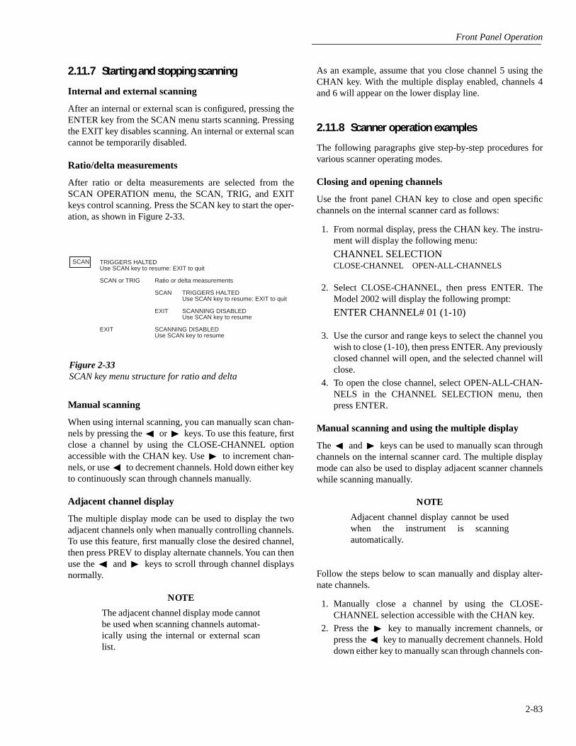
Front Panel Operation
2-83
2.11.7 Starting and stopping scanning
Internal and external scanning
After an internal or external scan is configured, pressing theENTER key from the SCAN menu starts scanning. Pressingthe EXIT key disables scanning. An internal or external scancannot be temporarily disabled.
Ratio/delta measurements
After ratio or delta measurements are selected from theSCAN OPERATION menu, the SCAN, TRIG, and EXITkeys control scanning. Press the SCAN key to start the oper-ation, as shown in Figure 2-33.
Manual scanning
When using internal scanning, you can manually scan chan-nels by pressing the or keys. To use this feature, firstclose a channel by using the CLOSE-CHANNEL optionaccessible with the CHAN key. Use to increment chan-nels, or use to decrement channels. Hold down either keyto continuously scan through channels manually.
Adjacent channel display
The multiple display mode can be used to display the twoadjacent channels only when manually controlling channels.To use this feature, first manually close the desired channel,then press PREV to display alternate channels. You can thenuse the and keys to scroll through channel displaysnormally.
NOTE
The adjacent channel display mode cannotbe used when scanning channels automat-ically using the internal or external scanlist.
As an example, assume that you close channel 5 using theCHAN key. With the multiple display enabled, channels 4and 6 will appear on the lower display line.
2.11.8 Scanner operation examples
The following paragraphs give step-by-step procedures forvarious scanner operating modes.
Closing and opening channels
Use the front panel CHAN key to close and open specificchannels on the internal scanner card as follows:
1. From normal display, press the CHAN key. The instru-ment will display the following menu:
CHANNEL SELECTION
CLOSE-CHANNEL OPEN-ALL-CHANNELS
2. Select CLOSE-CHANNEL, then press ENTER. TheModel 2002 will display the following prompt:
ENTER CHANNEL# 01 (1-10)
3. Use the cursor and range keys to select the channel youwish to close (1-10), then press ENTER. Any previouslyclosed channel will open, and the selected channel willclose.
4. To open the close channel, select OPEN-ALL-CHAN-NELS in the CHANNEL SELECTION menu, thenpress ENTER.
Manual scanning and using the multiple display
The and keys can be used to manually scan throughchannels on the internal scanner card. The multiple displaymode can also be used to display adjacent scanner channelswhile scanning manually.
NOTE
Adjacent channel display cannot be usedwhen the instrument is scanningautomatically.
Follow the steps below to scan manually and display alter-nate channels.
1. Manually close a channel by using the CLOSE-CHANNEL selection accessible with the CHAN key.
2. Press the key to manually increment channels, orpress the key to manually decrement channels. Holddown either key to manually scan through channels con-
SCAN TRIGGERS HALTEDUse SCAN key to resume: EXIT to quit
SCAN or TRIG Ratio or delta measurements
SCAN TRIGGERS HALTEDUse SCAN key to resume: EXIT to quit
EXIT SCANNING DISABLEDUse SCAN key to resume
EXIT SCANNING DISABLEDUse SCAN key to resume
Figure 2-33SCAN key menu structure for ratio and delta

Front Panel Operation
2-84
tinuously. Auto-repeat of cursor keys is disabled whenadjacent channel next display is shown.
3. With the unit in the normal display mode, press thePREV key to enable adjacent channel display. Note thatthe lower and upper adjacent channel readings will ap-pear on the lower display section.
4. Manually scan through channels with the or key.Note that the adjacent display channel numbers track thechannel on the main display.
5. Press the NEXT key to cancel the alternate channel dis-play mode, then use the CHAN key to open channelswhen done scanning.
Scanning internal channels
Internal channels are scanned by configuring scan channelsand programming the Model 2002 to perform a scan. Thefollowing steps demonstrate the basic procedures for per-forming basic scanning using the Model 2001-SCAN scan-ner card.
NOTE
Depending on selected trigger modes, itmay be necessary to trigger the instrumentto perform scanning. Refer to paragraph2.7 for detailed information on triggering.
Step 1: Configure channels
Use CONFIG-CHAN to select the measurement functionsfor each of the scanner channels as follows:
1. Press CONFIG-CHAN. The instrument will display thefollowing menu: CONFIGURE CHANNELS
INTERNAL-CHANS EXTERNAL-INPUTS SAVE-ALT-FCN RESTORE-ALT-FCN
2. Select INTERNAL-CHANS, then press ENTER. Themultimeter will display the following menu:
SET INTERNAL CHANS
1=DCV 2=DCV 3=DCV 4=DCV 5=DCV 6=DCV 7=DCV 8=DCV 9=DCV 10=DCV
3. Using the cursor keys, select the desired channel (pressthe right cursor key to display channels 6 through 10).
4. Using the range keys, select the desired measurementfunction: DCV, ACV,
Ω
2W,
Ω
4W, FRQ, TMP, ALT,JN1, JN2, JN3, JN4, JN5, --- (None).
5. Repeat steps 3 and 4 for each of the channels you wishto scan. Note: Select --- (none) to omit a channel fromthe scan list.
6. Examine all ten channels to verify omitted channels andpaired (PRD) channels.
7. After selecting all measurement functions, press EN-TER to return to normal display.
Step 2: Select internal scan list
Use the SCAN OPERATION menu to select the internalscan list as follows:
1. Press CONFIG-SCAN. The Model 2002 will displaythe following:
SCAN OPERATION
INTERNAL EXTERNAL RATIO DELTA
2. Select INTERNAL, then press ENTER.
Step 3: Start scan
After configuring channels and scan list, simply press theSCAN key to begin scanning. The instrument will promptyou to configure the scan count and scan timer, and to enabledata storage. Pressing the ENTER key will scan throughselected channels and make a measurement on each channelusing the previously selected measurement function for eachchannel. When the scan has completed, you can recall storeddata and/or scan again. To disable scanning, press the EXITkey.
Using ratio and delta
The Model 2002 can display the difference (DELTA) or quo-tient (RATIO) between the signal on any two internal scan-ner channels. The following paragraphs discuss ratio anddelta calculations and also give step-by-step procedures forusing ratio and delta.
When the instrument is first placed in the ratio or delta mode,it will close the scanner reference channel and then wait fora trigger. When the reading is triggered, the unit will make ameasurement on the reference channel, switch to the mea-surement channel, and then take a second measurement.After measuring the measurement channel, the unit willcompute and display the ratio or delta value, and switch backto the reference channel to wait for the next trigger.
The steps below outline the basic procedure for making ratiomeasurements. The procedure for delta measurements isessentially the same, except that you would select DELTA inthe appropriate menu.
Step 1: Connect inputs
Input signals must be connected to the two channels youintend to define as measurement and reference channels.

Front Panel Operation
2-85
Step 2: Define measurement channel
1. From normal display, press CONFIG-SCAN. The in-strument will display the following:
SCAN OPERATIONINTERNAL EXTERNAL RATIO DELTA
2. Select RATIO, then press ENTER. The Model 2002 willdisplay the following:
CONFIGURE RATIOMEASURE REFERENCE FUNCTION
3. Select MEASURE, then press ENTER. The instrumentwill display the following:
RATIO MEASURE CHANCH1 2 3 4 5 6 7 8 9 10
4. Using the cursor keys, select the channel you wish todefine as the measure channel, then press ENTER.
Step 3: Define reference channel
1. From the CONFIGURE RATIO menu, select REFER-ENCE, then press ENTER. The Model 2001 will displaythe following message:
RATIO REFERENCE CHANCH1 2 3 4 5 6 7 8 9 10
2. Using the cursor keys, select the channel to be definedas the reference channel, then press ENTER.
Step 4: Select measurement function
1. From the CONFIGURE RATIO menu, select FUNC-TION, then press ENTER. The instrument will displaythe following:
SET RATIO FUNCTIONDCV Ω2 Ω4
Note that only DC volts, and 2- and 4-wire ohms func-tions are available for ratio and delta modes.
2. Use the cursor keys to select the desired function, thenpress ENTER.
3. Press EXIT as necessary to return to normal display.
Step 5: Display ratio readings
Once the reference channel, measurement channel, and ratiofunction have been defined, press SCAN to halt triggers, thenpress TRIG or SCAN to display ratio readings. The instru-ment will automatically display ratio readings computedfrom signals applied to the reference and measurement chan-nels. If you have selected a trigger mode that requires a sep-arate trigger for each reading, you will, of course, have to
trigger the instrument to obtain each ratio reading (refer toparagraph 2.7 for details on triggering).
Step 6: Disabling and cancelling the ratio mode
You can disable the ratio mode by pressing EXIT while ratioreadings are being displayed. To cancel the ratio mode, pressCONFIG-SCAN, then select another option under theSCAN-OPERATION menu.
RTD temperature measurements
The following paragraphs outline the basic procedures formaking RTD temperature measurements using the internalscanner. For more detailed information on temperature mea-surements in general, refer to paragraph 2.4.5.
Step 1: Connect RTD probes
Connect RTD probes to the scanner using the basic resis-tance connections outlined in the scanner card manual. For4-wire probes, pair the connections as follows:
• Channels 1 and 6: probe #1
• Channels 2 and 7: probe #2
• Channels 3 and 8: probe #3
• Channels 4 and 9: probe #4
• Channels 5 and 10: probe #5
Step 2: Select sensor type and units
Use the CONFIGURE CHANNELS menu to select the RTDsensor type and the units you wish to display. See paragraph2.4.5 for details.
Step 3: Configure channels
1. Press CONFIG-CHAN. The instrument will display thefollowing:
CONFIGURE CHANNELSINTERNAL-CHANS EXTERNAL-INPUTS
SAVE-ALT-FCN RESTORE-ALT-FCN
2. Select INTERNAL-CHANS. The Model 2002 will dis-play the following:
SET INTERNAL CHANNELS1=DCV 2=DCV 3=DCV 4=DCV 5=DCV
6=DCV 7=DCV 8=DCV 9=DCV 10=DCV
3. Use the cursor and range keys to select channels andfunctions. Set the function type to TMP for all channelsconnected to RTD probes. Select --- (none) for channelswithout probes connected.
4. Press ENTER to return to normal display.
Front Panel Operation
2-86
Step 4: Configure scan
1. From normal display, press CONFIG-SCAN. Theinstrument will display the following:
SCAN OPERATIONINTERNAL EXTERNAL RATIO DELTA
2. Select INTERNAL, then press ENTER.
Step 5: Scan channels
To start scanning, press the SCAN key and program the scancount, scan timer, and data storage. Then press ENTER.When the scan has completed, you can recall stored data and/or scan again. Press EXIT while scanning to interrupt datastorage and disable scanning.
Using the scanner with the data storage buffer
The Model 2002 internal data storage buffer can be used tostore readings taken while using the scanner. The followingparagraphs outline the basic steps necessary for data storageof scanner readings. Refer to paragraph 2.8 for additionalinformation on using the data storage buffer.
Step 1: Configure channels
1. Press CONFIG-CHAN. The instrument will display thefollowing:
CONFIGURE CHANNELSINTERNAL-CHANS EXTERNAL-INPUTS
SAVE-ALT-FCN RESTORE-ALT-FCN
2. Select INTERNAL-CHANS. The Model 2002 will dis-play the following:
SET INTERNAL CHANNELS1=DCV 2=DCV 3=DCV 4=DCV 5=DCV
6=DCV 7=DCV 8=DCV 9=DCV 10=DCV
3. Use the cursor and range keys to select channels andfunctions, then press ENTER when you have set allfunctions and channels.
Step 2: Configure scan
1. From normal display, press CONFIG-SCAN. Theinstrument will display the following:
SCAN OPERATIONINTERNAL EXTERNAL RATIO DELTA
2. Select INTERNAL, then press ENTER.
Step 3: Trigger scan
Press SCAN to program the scan count, scan timer, data stor-age and select YES to the “Data to memory?” prompt. Thenpress ENTER. The unit will cycle through the channels,stopping to take and store a reading on each channel.
Step 4: Recall readings
From the SCAN COMPLETE menu, select the RECALL-DATA option to display readings stored in the buffer. Use thecursor and range keys to select the reading number to dis-play. Note that the instrument will display the channel num-ber for each buffer reading in addition to other pertinentbuffer information. Press EXIT to return to the SCAN COM-PLETE menu.
External scanning
Follow the general steps below to set Model 2002 modes forexternal scanning.
Step 1: Make scanner card connections
Be sure to connect your scanner signal lines and triggercables as appropriate. See the scanner card documentationfor details on signal connections. Paragraphs 2.7.6 and 2.7.7provide information on external triggering and using the trig-ger link.
Step 2: Configure trigger parameters
Using CONFIG-TRIG, select the required trigger layer pa-rameters based on the desired scanner and multimeter oper-ation. See paragraph 2.7 for Model 2002 trigger parameterdetails.
Step 3: Configure external channels and functions
1. From normal display, press CONFIG-CHAN. The in-strument will display the following:
CONFIGURE CHANNELSINTERNAL-CHANS EXTERNAL-INPUTS
SAVE-ALT-FCN RESTORE-ALT-FCN
2. Select EXTERNAL-INPUTS, then press ENTER. TheModel 2002 will prompt you to enter the number ofchannels:
# EXTERNAL INPUTS=80
3. Use the range and cursor keys to set the number of exter-nal channels you will be using, then press ENTER. Theinstrument will prompt you to set functions:
SET CHAN FUNCTIONSDEFAULT CHOOSE-FUNCTIONS

Front Panel Operation
2-87
4. If you wish to use the current default function for allchannels, select DEFAULT, then press ENTER.
5. If you intend to program a separate function for eachchannel, choose CHOOSE-FUNCTIONS, then pressENTER. The instrument will prompt you for a channelnumber, as in the following typical display:
SELECT CHAN=01 (DCV)
6. Use the cursor and range keys to select a channel, thenpress ENTER. Select the desired function, then pressENTER. Repeat the procedure for all channels to bedefined.
7. Press EXIT as necessary to return to normal display.
Step 4: Enable external scanning
1. From normal display, press CONFIG-SCAN. The in-strument will display the following:
SCAN OPERATIONINTERNAL EXTERNAL RATIO DELTA
2. Select EXTERNAL, then press ENTER.
Step 5: Start scan
Press SCAN for instructions to set up the external scanner,program the scan count, scan timer, and data storage. Thenpress ENTER to start scanning. When the scan has complet-ed you can recall stored data and/or scan again. Press EXITto interrupt data storage and disable scanning.
2.12 Menu
The main menu accesses the various instrument operationsfor which there are no dedicated keys, such as setup storage,IEEE-488 setup, calibration, self-test, and limits. The mainmenu structure is summarized in Table 2-41.
The top level of the main menu is displayed by placing theinstrument in the reading display state, and then pressing theMENU key.
Some general rules to navigate the menu levels are given inparagraph 2.3.4.

Front Panel Operation
2-88
Table 2-41Main menu structure
Menu item Description
SAVESETUPSAVERESTOREPOWERON
BENCHGPIBUSER-SETUP-NUMBER
RESETBENCHGPIB
Setup menu:Save setup at a memory location (up to 1, 5, or 10).Return 2002 to setup stored at a memory location (up to 1, 5, or 10).Power-on Menu:
Power on to bench default setup conditions.Power on to GPIB default setup conditions.Power on to setup stored at a memory location (up to 1, 5, or 10).
Reset Menu:Return 2002 to bench default setup.Return 2002 to GPIB default setup.
GPIBADDRESSABLETALK-ONLY
FEEDAFTER-CALCBEFORE-CALCNONE
INTERFACEIEEE-488CENTRONICS
INTERVALFORMFEED
CONTROLSET-PAGE-SETUP
ELEMENTS
STATUS
GPIB/Printer Setup menu:Check/change IEEE-488 bus address (0-30).GPIB/Printer Talk-only mode menu:
GPIB Output Feed menu:Specify reading after math operation.Specify reading before math operation.Specify no readings.
Select printer interface.Specify IEEE-488 printer.Specify Centronics parallel printer.
Specify printing interval (every reading to 1 out of 9999).Formfeeds menu:
Enable/disable page breaks.Set number line between form feeds (1-255).
Select GPIB data elements (reading, units, reading number, channel number, timestamp, status).
Display IEEE-488 bus status byte.
CALIBRATIONCOMPREHENSIVEPOINT CALCALIBRATION-DATES
Calibration menu:Perform DC and AC calibration.Perform point calibrations.Check/change calibration date.
TESTBUILT-IN-TEST
AUTOMATICMANUAL
DIAGNOSTICSFRONT-PANEL-TESTS
KEYSDISPLAY-PATTERNS
Self-test menu:Test analog and digital boards.
Run all tests automatically.Select tests to run.
Factory diagnostic tests.Test display board.
Verify operation of front panel keys.Verify operation of display.

Front Panel Operation
2-89
LIMITSLIMIT-SET-1
CONTROLLOLIM1HILIM1
LIMIT-SET-2CONTROLLOLIM2HILIM2
STROBE-CONTROLPASS-PATTERN
Limits menu:Limit-Set-1 menu:
Enable/disable limit set #1.Set value of low limit #1.Set value of high limit #1.
Limit-Set-2 menu:Enable/disable limit set #2.Set value of low limit #2.Set value of high limit #2.
Enable/disable limit strobe signal of digital output #4 when trigger occurs.Specify patterns on digital outputs to signify limits pass.
STATUS-MSG Enable/disable status message mode.
GENERALDIGITAL-I/O
OUTPUT-STATEOUTPUT-SENSEINPUT
SERIAL#A/D CONTROLS
LINE-SYNC
AUTO-ZEROTIMESTAMP
TYPERELATIVE-TIMEREAL-TIME
RESET-TIMERESET-RDG#
DECIMALCLOCK
TIMEDATEFORMAT
12-HOUR24-HOUR
General menu:Digital I/O menu:
Check/change states of digital output lines.Check/change sense of digital output lines.Read digital input line.
Display serial number, memory option SCPI version, and firmware revisions.A/D menu:
Enable/disable line synchronization of measurements. Also, displays the power line frequency.Disable or enable normal or synchronous autozero mode.
Configure timestamp:Check or change type.
Reference timestamp to relative time.Reference timestamp to real time.
Reset relative timestamp to zero.Reset reading number to zero.
Select period or comma for display of decimal point.Clock menu:
Check or set time of day.Check or set date.Select clock format:
12-hour format (AM, PM).24-hour format.
Table 2-41Main menu structure (cont.)
Menu item Description

Front Panel Operation
2-90
2.12.1 SAVESETUP
The SAVESETUP option of the main menu is used for thefollowing operations:
• To save the present instrument configuration in non-volatile memory.
• To restore the instrument to a previously saved instru-ment configuration.
• To set the instrument’s power-on configuration.
• To reset the instrument to a factory defaultconfiguration.
SAVE
Use this menu item to save the present instrument setup in aspecific memory location. Depending on the memory option,you can store up to one (STD), five (MEM1), or ten (MEM2)setups in non-volatile memory. The installed memory optionis displayed on power-up, and in the SERIAL# option of theGeneral Menu (see paragraph 2.12.7).
After selecting SAVE, you will be prompted to save thepresent setup in a memory location. Note that the numberingof setup locations starts with setup #0. You can save the setupat memory location #0 or you can use the RANGE and keys to enter a different value. With the desired memorylocation displayed, press ENTER.
RESTORE
Use this menu item to return the instrument to a setup thatwas previously stored (see SAVE) in memory.
After selecting RESTORE you will be prompted to enter thememory location number of the setup that you wish torestore. Note that #0 is a valid memory location. Use therange keys ( and ) to key in the desired location and pressENTER. The instrument will immediately restore that setupconfiguration.
POWERON
Use this menu item to select the instrument setup that goesinto effect on power-on.
The instrument can be set to power on to the factory benchdefaults, the factory GPIB defaults, or to a user setup stored(see SAVE) at a specific memory location. These POW-ERON options are explained as follows:
BENCH: Use this option to return the instrument to thebench default conditions (see Table 2-42) the next time it isturned on.
GPIB: With this option, the unit returns to the GPIB defaultconditions (see Table 2-42) the next time it is turned on.
USER-SETUP-NUMBER: Using this option, the instru-ment powers on to a user setup saved at a specific memorylocation (see SAVE).
After selecting USER-SETUP-NUMBER, you will beprompted to enter the memory location number of the setupthat you wish the instrument to power up to. Note that #0 isa valid memory location. Use the range keys ( and ) tokey in the desired memory location and press ENTER.
RESET
Use this menu option to reset the instrument to the bench orGPIB default conditions (see Table 2-42).
The RESET options are explained as follows:
BENCH: With this option, the instrument returns to thebench default conditions (see Table 2-42). After selectingBENCH, the instrument returns to the normal display ofreadings after requesting an ENTER to confirm yourselection.
GPIB: With this option, the unit returns to the GPIB defaultconditions (see Table 2-42). After selecting GPIB, the instru-ment returns to the normal display of readings after request-ing an ENTER to confirm your selection. Note that theinstrument goes to the Idle state.
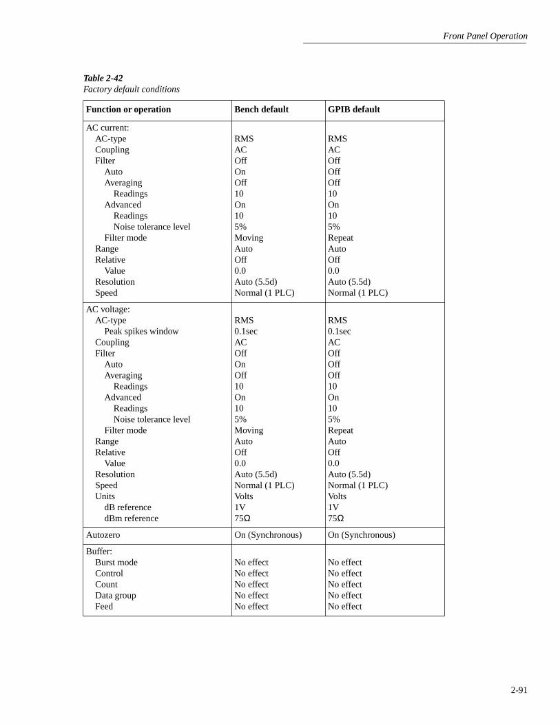
Front Panel Operation
2-91
Table 2-42Factory default conditions
Function or operation Bench default GPIB default
AC current:AC-type Coupling Filter
Auto Averaging
Readings Advanced
Readings Noise tolerance level
Filter mode Range Relative
Value Resolution Speed
RMS AC OffOnOff10 On10 5%Moving Auto Off 0.0 Auto (5.5d) Normal (1 PLC)
RMSACOffOffOff10On105%RepeatAutoOff0.0Auto (5.5d)Normal (1 PLC)
AC voltage:AC-type
Peak spikes window Coupling Filter
Auto Averaging
Readings Advanced
Readings Noise tolerance level
Filter mode Range Relative
Value Resolution Speed Units
dB reference dBm reference
RMS 0.1secAC Off OnOff10 On10 5%Moving Auto Off 0.0 Auto (5.5d) Normal (1 PLC) Volts 1V 75Ω
RMS0.1secACOffOffOff10On105%RepeatAutoOff0.0Auto (5.5d)Normal (1 PLC)Volts1V75Ω
Autozero On (Synchronous) On (Synchronous)
Buffer:Burst modeControlCountData groupFeed
No effectNo effectNo effectNo effectNo effect
No effectNo effectNo effectNo effectNo effect

Front Panel Operation
2-92
DC current:Filter
Auto Averaging
Readings Advanced
Readings Noise tolerance level
Filter mode Measurement mode Range Relative
Value Resolution Speed
OnOnOff10 On10 1%Moving Normal Auto Off 0.0 Auto (6.5d)Normal (1 PLC)
OffOffOff10On101%RepeatNormalAutoOff0.0Auto (6.5d)Normal (1 PLC)
DC voltage:Filter
Auto Averaging
Readings Advanced
Readings Noise tolerance level
Filter mode Range Relative
Value Resolution Speed
OnOnOff10 On10 1%Moving Auto Off 0.0 Auto (7.5d) Normal (1 PLC)
OffOffOff10On101%RepeatAutoOff0.0Auto (7.5d)Normal (1 PLC)
Digital I/O:Output states Output sense
No effectNo effect
No effectNo effect
Frequency:Coupling Maximum signal level:
Function Voltage level Current level
Relative Value
Resolution Terminals Trigger level
AC
Voltage 10V 1mA Off 0.0 Auto (5d) Voltage 0.0
AC
Voltage10V1mAOff0.0Auto (5d)Voltage0.0
Function DCV DCV
Table 2-42Factory default conditions (cont.)
Function or operation Bench default GPIB default

Front Panel Operation
2-93
Limits:Limit set #1
Low limit #1 Low limit #1 action High limit #1 High limit #1 action
Limit set #2 Low limit #2 Low limit #2 action High limit #2 High limit #2 action
Strobe control Pass pattern
Off -1.0 0 1.0 0 Off -1.0 0 1.0 0 Off 0
Off-1.001.00Off-1.001.00Off0
Line synchronization Off Off
Math Function Reference for percent “a0” factor for polynomial“a1” factor for polynomial“a2” factor for polynomial
Off Percent 1.0 01 0
OffPercent1.0010
Resistance (2-wire):Filter
Auto Averaging
Readings Advanced
Readings Noise tolerance level
Filter mode Offset compensation Range
Maximum autorange Relative
Value Resolution Speed
OnOnOff10 On10 1%Moving Off Auto 1GΩ Off 0.0 Auto (7.5d) Normal (1 PLC)
OffOffOff10On101%RepeatOffAuto1GΩOff0.0Auto (7.5d)Normal (1 PLC)
Table 2-42Factory default conditions (cont.)
Function or operation Bench default GPIB default

Front Panel Operation
2-94
Resistance (4-wire):Filter
Auto Averaging
Readings Advanced
Readings Noise tolerance level
Filter mode Offset compensationRange
Maximum autorange Relative
Value Resolution Speed
OnOnOff10 On10 1%Moving Off Auto 2MΩ Off 0.0 Auto (7.5d) Normal (1 PLC)
OffOffOff10On101%RepeatOffAuto2MΩOff0.0Auto (7.5d)Normal (1 PLC)
Scanning:Channels Scan list:
Internal list External list Function
Scan operation Ratio:
Reference channel Measure channel Function
Delta:Reference channel Measure channel Function
No effect
No channels No channels DC voltage None
5 10 DC voltage
5 10 DC voltage
No effect
No channelsNo channelsDC voltageNone
510DC voltage
510DC voltage
Table 2-42Factory default conditions (cont.)
Function or operation Bench default GPIB default

Front Panel Operation
2-95
Temperature:Filter
Auto Averaging
Readings Filter mode
Relative Value
Resolution RTDs:
Type Resistance at 0°C Alpha Beta Delta
Sensor Speed Thermocouples:
Type Reference junction
Default temperature Real junction temp.
coefficient Offset
Units
OnOnOn10 Moving Off 0.0 Auto (0.01°C)
PT100100Ω 0.00385 0.108631.499904-wire RTD Normal (1 PLC)
J Simulated 23°C 10mV/°C
0mV @ 0°C°C
OffOffOn10RepeatOff0.0Auto (0.01°C)
PT100100Ω0.003850.108631.499904-wire RTDNormal (1 PLC)
JSimulated23°C10mV/°C
0mV @ 0°C°C
Triggers: arm layer:
Source Triglink input Triglink output
Count Control
scan layer:Source
Triglink input Triglink output
Delay Count Control
measure layer:Source
Triglink mode Triglink input Triglink output Timer
Delay Count Control
Armed
Immediate Line 2 Line 1 1 Acceptor
Immediate Line 2 Line 1 0 Infinite Acceptor
Immediate Asynchronous Line 2 Line 1 0.1sec0 InfiniteAcceptor
Idled
ImmediateLine 2Line 11Acceptor
ImmediateLine 2Line 101Acceptor
ImmediateAsynchronousLine 2Line 10.1sec01Acceptor
Table 2-42Factory default conditions (cont.)
Function or operation Bench default GPIB default

Front Panel Operation
2-96
2.12.2 GPIB
The GPIB menu is used for the following operations:
• To view or change the IEEE-488 address.
• To select the talk-only mode and its parameters.
• To select the data elements to send.
• To view the status byte of the instrument.
Changing between “Addressable” and “Talk-only” causestriggers to be halted.
ADDRESSABLE
With the instrument set for “Addressable”, it can listen andtalk to a bus controller. This menu item lets you check and/or change the IEEE-488 address of the instrument. At thefactory the address is set to 16, but it can be changed to anyvalue from 0 to 30.
After selecting ADDRESSABLE, the present IEEE-488address will be displayed. If you wish to change the address,use the RANGE and keys to display the desired numberand press ENTER.
TALK-ONLY
In the talk-only mode, the Model 2002 ignores commandsfrom the bus and merely outputs data, as requested by theprinter. When the instrument is in the talk-only mode, theTALK annunciator turns on.
The options for TALK-ONLY are explained as follows:
FEED: This item has options that select the type of readingsprinted: readings after a math operation is performed(AFTER-MATH), readings before a math operation(BEFORE-MATH), or no readings (NONE).
INTERFACE: With the IEEE-488 option of this item, dataelements are sent to an IEEE-488 bus printer set for listenalways. With the CENTRONICS option, data elements aresent to a printer with a Centronics (parallel) interface. Theprinter must be connected with a Model 8530 IEEE-488 toCentronics Printer Adapter Cable.
INTERVAL: The INTERVAL option controls how oftenreadings are printed (expressed as 1 out of nnnn readings).
FORMFEED: Use the FORMFEED option of the menu toenable or disable the sending of a formfeed character to theprinter after printing a user-selectable number of lines perpage (1-255 lines).
ELEMENTS
This menu item lets you select the data elements sent:
• Reading The numeric value of the reading.
• Units The units of the reading.
• Reading# The buffer location of the reading. Thereading number can be reset to zero from the GEN-ERAL MENU (see paragraph 2.12.7).
• Chan# The channel number on which the readingwas taken.
• Timestamp The real-time or relative timestamp foreach reading. Timestamp type is selected from theGENERAL MENU (see paragraph 2.12.7).
• Status The reading status information (normal read-ing, measurement overflow, relative reading).
STATUS
Use this menu item to view the IEEE-488 status byte. Referto Section 3 (IEEE- 488 Reference) for information on thestatus byte.
The bits in the status byte are refreshed by exiting and re-entering its menu.
2.12.3 CALIBRATION
The CALIBRATION menu is used for the followingoperations:
• To perform comprehensive calibration.
• To perform point calibration.
• To view or change the calibration date.
Some of the menu items are locked to prevent unintendedchanging of calibration constants.
COMPREHENSIVE
The procedure for comprehensive calibration is locked; toenable it requires the CAL switch to be pressed. The proce-dure uses accurate calibration equipment to supply preciseDC voltages, DC currents and resistance values. Refer to theModel 2002 Calibration Manual for instructions.
POINT-CALS
This menu item is used to perform calibration for selectedfunctions. AC calibration requires no external equipment andcan be performed by the operator at any time to ensure theaccuracy of ACV and ACI measurements.
Front Panel Operation
2-97
DCV, ohms, and DCI calibration requires the use of accuratecalibration equipment and is only intended to be performedby qualified service personnel. Refer to the Model 2002 Cal-ibration Manual to calibrate these functions.
AC-CAL: Use this menu item to perform the AC self-calibration procedure.
NOTE
The AC calibration constants generated bythis procedure are not permanently stored.They are in effect only until the power isturned off. To permanently store AC cali-bration constants, refer to the Model 2002Calibration Manual.
To perform an AC-only calibration, follow these steps:
1. The Model 2002 must be allowed to warm up for at leastone hour before calibration.
2. Disconnect all test leads or cables from the front andrear INPUT and SENSE jacks.
3. Select POINT-CALS from the PERFORM CALIBRA-TION menu.
4. Press ENTER to begin AC calibration, which takesabout six minutes to complete.
NOTE
All keypresses are locked out when a cali-bration step is in progress.
5. Once the process has successfully completed, the “ACCAL COMPLETE” message is displayed, and you canpress ENTER or EXIT to return to a normal display.
DCV, OHMS and DCI: These menu items are used to cali-brate DCV, ohms and DCI. The calibration procedures arelocked out to prevent accidental changing of calibration con-stants. These calibration procedures should only be per-formed by qualified service personnel. Refer to the Model2002 Calibration Manual for details on performing point cal-ibration for these functions.
CALIBRATION-DATES
Use this menu item to view or change the calibration dates.
Use the VIEW option of the menu to display the lastcalibration date and the next calibration date. The DISPLAY-AT-POWERUP option controls whether the next calibrationdate is displayed during the power-up sequence.
The CHANGE option is locked; to enable it requires theCAL switch to be pressed. The option allows you to changethe calibration date and next calibration date. Refer to theModel 2002 Calibration Manual for instructions.
2.12.4 TEST
The SELF-TEST MENU is used as a diagnostic tool to iso-late problems with the Model 2002. Information on usingthese test procedures is included in the optional Model 2002Repair Manual.
2.12.5 LIMITS
The LIMITS menu is used for the following operations:
• To set and control the limit values that determine thePASS/FAIL and HI/LO status of subsequent measure-ments.
• To set the digital output patterns that signify passing orfailing limit checks.
• To enable/disable a binning strobe signal on digital out-put #4 for triggering a user-supplied device handler.
NOTE
Since the logic sense of the digital outputlines is programmable (high-true or low-true), this discussion of limits uses the log-ical terms TRUE/FALSE and ON/OFF,rather than HIGH and LOW.
There are two sets of limits, each with high and low limit val-ues. You can program and enable one or both limit sets. Withboth sets enabled, the values can overlap or one set can beincluded in the other. The only restriction is that, within thesame set, the high limit must be greater than the low limit fora valid test.
The limit test is performed after polynomial and percentmath operations. Unit prefixes are applied before the limittest, for example:
• Low limit = -1.0, High limit = 1.0.A 150mV reading equals 0.15V (PASS).
• Low limit = -1.0, High limit = 1.0.A 0.6kΩ reading equals 600Ω (FAIL).
Limit set #1 is available as a multiple display, which showsa bar graph and a pass/fail indication for the measurements.(Note: The PASS/FAIL indication is not available for ACV,
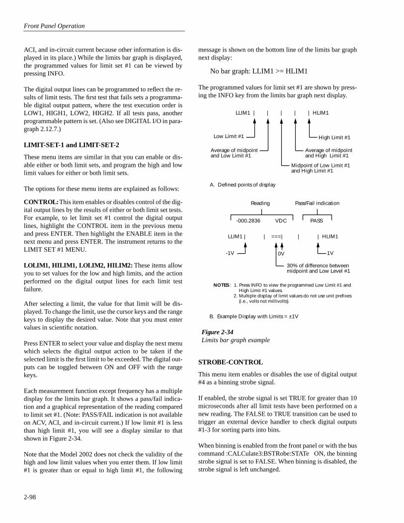
Front Panel Operation
2-98
ACI, and in-circuit current because other information is dis-played in its place.) While the limits bar graph is displayed,the programmed values for limit set #1 can be viewed bypressing INFO.
The digital output lines can be programmed to reflect the re-sults of limit tests. The first test that fails sets a programma-ble digital output pattern, where the test execution order isLOW1, HIGH1, LOW2, HIGH2. If all tests pass, anotherprogrammable pattern is set. (Also see DIGITAL I/O in para-graph 2.12.7.)
LIMIT-SET-1 and LIMIT-SET-2
These menu items are similar in that you can enable or dis-able either or both limit sets, and program the high and lowlimit values for either or both limit sets.
The options for these menu items are explained as follows:
CONTROL: This item enables or disables control of the dig-ital output lines by the results of either or both limit set tests.For example, to let limit set #1 control the digital outputlines, highlight the CONTROL item in the previous menuand press ENTER. Then highlight the ENABLE item in thenext menu and press ENTER. The instrument returns to theLIMIT SET #1 MENU.
LOLIM1, HILIM1, LOLIM2, HILIM2: These items allowyou to set values for the low and high limits, and the actionperformed on the digital output lines for each limit testfailure.
After selecting a limit, the value for that limit will be dis-played. To change the limit, use the cursor keys and the rangekeys to display the desired value. Note that you must entervalues in scientific notation.
Press ENTER to select your value and display the next menuwhich selects the digital output action to be taken if theselected limit is the first limit to be exceeded. The digital out-puts can be toggled between ON and OFF with the rangekeys.
Each measurement function except frequency has a multipledisplay for the limits bar graph. It shows a pass/fail indica-tion and a graphical representation of the reading comparedto limit set #1. (Note: PASS/FAIL indication is not availableon ACV, ACI, and in-circuit current.) If low limit #1 is lessthan high limit #1, you will see a display similar to thatshown in Figure 2-34.
Note that the Model 2002 does not check the validity of thehigh and low limit values when you enter them. If low limit#1 is greater than or equal to high limit #1, the following
message is shown on the bottom line of the limits bar graphnext display:
No bar graph: LLIM1 >= HLIM1
The programmed values for limit set #1 are shown by press-ing the INFO key from the limits bar graph next display.
STROBE-CONTROL
This menu item enables or disables the use of digital output#4 as a binning strobe signal.
If enabled, the strobe signal is set TRUE for greater than 10microseconds after all limit tests have been performed on anew reading. The FALSE to TRUE transition can be used totrigger an external device handler to check digital outputs#1-3 for sorting parts into bins.
When binning is enabled from the front panel or with the buscommand :CALCulate3:BSTRobe:STATe ON, the binningstrobe signal is set to FALSE. When binning is disabled, thestrobe signal is left unchanged.
Figure 2-34Limits bar graph example
LLIM1 | | | | | HLIM1
Low Limit #1
Average of midpointand Low Limit #1
High Limit #1
Average of midpointand High Limit #1
Midpoint of Low Limit #1and High Limit #1
A. Defined points of display
Reading Pass/Fail indication
-000.2836 VDC PASS
NOTES : 1. Press INFO to view the programmed Low Limit #1 and High Limit #1 values.
2. Multiple display of limit values do not use unit prefixes (i.e., volts not millivolts).
B. Example Display with Limits = ±1V
-1V
LLIM1 | | ===| | | HLIM1
1V0V
30% of difference betweenmidpoint and Low Level #1

Front Panel Operation
2-99
DISABLED: Use this selection to disable strobe control.
ENABLED: Use this selection to enable strobe control.
PASS-PATTERN
This item allows you to program the on/off states of the dig-ital output lines for when all limit tests pass. Note that whenthe binning strobe is enabled, digital output line #4 cannot beused.
Selecting PAS-PATTERN displays the digital output patternthat occurs when all limit tests pass. To change the pattern,use the cursor keys and the range keys. The range keys togglethe parameter values between OFF and ON.
Limits example
This example sorts a quantity of 100Ω resistors into five bins,according to the following tolerances:
• Values less than 90Ω (outside -10% tolerance).
• Values greater than 110Ω (outside +10% tolerance).
• Values between 90Ω and 99Ω (meets -10% tolerance).
• Values between 101Ω and 110Ω (meets +10% toler-ance).
• Values between 99Ω and 101Ω (meets ±1% tolerance).
The desired test is shown in Figure 2-35. Use the followingprocedure to program the limits:
1. From the LIMITS menu, set the limit values and actionsaccording to the following table:
2. Enable the binning strobe signal from the STROBE-CONTROL item of the LIMITS menu.
3. Set a pass pattern of all lines off from the PASS PAT-TERN item of the LIMITS menu.
4. Enable the control of the digital output lines by limit set#1 and limit set #2 from the LIMIT SET #1 and LIMITSET #2 menus. This sets the digital output lines to the“pass pattern” (all OFF in this example). Since binningis enabled, digital output #4 is also OFF.
Note that the actual state (high or low) of the digital outputlines depends on the polarity (ACTIVE-HIGH or ACTIVE-LOW). This is programmed from the DIGITAL I/O selectionof the GENERAL menu.
2.12.6 STATUS-MSG
This selection is used to enable or disable the status messag-es mode. When enabled, status messages are displayed toidentify specific operations that are performed.
ON: Enable the status message mode.
OFF: Disable the status message mode.
The instrument may become so busy displaying status mes-sages, that keypresses are no longer acknowledged. You mayhave to clear status message display by pressing the EXITkey or sending a bus command (:DISPlay:SMESsage OFF)to get out of this mode.
2.12.7 GENERAL
The GENERAL menu is used for the following operations:
• To control the state and sense of the digital outputs; toview the state of the digital input.
• To view the serial number, memory option, SCPI ver-sion, and firmware revision levels of the Model 2002.
• To control the frequency of autozero readings and to setline synchronization of readings.
• To configure timestamp.
• To choose the character displayed for a decimal.
• To set the real-time clock.
Limit Value Action
LOLIM1 90Ω DIGOUT1=ON, others OFF
HILIM1 110Ω DIGOUT2=ON, others OFF
LOLIM2 99Ω DIGOUT1=ON, DIGOUT2= ON, others OFF
HILIM2 101Ω DIGOUT3=ON, others OFF
Figure 2-35Using limit test to sort 100Ω resistors
ToleranceBands ±10%
±1%
Resistance
BitPatternsandLimits
90Ω 99Ω 101Ω 110Ω
001 011 000 100 010
LOLIM1 LOLIM2 HILIM2 HILIM1

Front Panel Operation
2-100
DIGITAL I/O
Overview
The Model 2002’s Digital I/O port is a 9-pin “D” sub-miniature connector located on the rear panel. The port’slocation and pin designations are shown in Figure 2-36.
The Model 2002’s Digital I/O port can be used to controlexternal circuitry. The port provides four output lines andone input line. Each open-collector output can be set high(+5V) or low (0V) and will sink up to 100mA. A TTL highon the Model 2002’s digital input is read as “ON”. The fouroutput lines can also operate external supplies from +5V to+30V.
Use the DIGITAL I/O Menu to select the following options:
• OUTPUT-STATE
ON or OFF selectable for each output line (1 through4). Use to check or change the output state.
• OUTPUT-SENSE
ACTIVE-HIGH or ACTIVE-LOW selectable for eachoutput line (TTL1 through TTL4). Use to check orchange the output sense.
• INPUT
ON or OFF. Use to check or change the status of thedigital input line. Sense is fixed at active-high(ON=5V).
Controlling digital circuitry
Each of the four digital, open-collector outputs (connectorJ1031, pins 6 through 9) includes a built-in pull up resistor to+5V. The output transistor is capable of sinking up to 100mAfrom voltages up to +30V. The outputs can be controlledindependently or tied to one of four limit values (two high,two low). Paragraph 2.12.5 contains information about con-trolling digital outputs from the limits menu.
Early versions of the Model 2002 have an additional 10kΩresistor connected between the collector and the internalbuilt-in test circuitry. Under certain combinations of outputstates, this resistor limits the output high to 2.5V.
For example:
Output #1 set high (+5V)
Outputs #2, #3, and #4 set low (0V)
Output #1 is restricted to +2.5V
If using the digital output to sink current from externaldevices, a Model 2002 containing the additional 10kΩ resis-tor will function correctly. The transistor switch is openrestricting current flow through the external device in thehigh state (+5V). However, if the output is directly used as aninput to a typical logic input, the 2.5V high state may not bereliably detected as a high. To correct this condition (if a2.5V high is unacceptable), add external 1kΩ pull up resis-tors to the logic circuit inputs, remove the built-in test resis-tors (R734, R737, R739, and R741), or use an externalvoltage supply.
External voltage supply
Each output can be operated from external voltage supplies(voltage range from +5V to +30V applied through the devicebeing driven). Refer to Figure 2-37 for a simplified schemat-ic of the digital I/O port. The high current sink capacity of theoutput driver allows direct control of relays, solenoids, andlamps, with no additional circuitry needed. Each outputchannel contains a fly-back diode for protection whenswitching inductive loads (such as a low power solenoid orrelay coils). To use these fly-back diodes, connect the exter-nal supply voltage to pin 4 of J1031 (the digital I/O port).Make sure the external supply voltage is between +5V and+30V and the current required by the device does not exceed100mA.
Figure 2-36Digital I/O port
1 = Digital Input2 = N/C3 = N/C4 = Vext fly-back connection (+5V to 30V)5 = Digital Ground6 = Digital Output #17 = Digital Output #28 = Digital Output #49 = Digital Output #3
Digital I/O Receptacle
5 19 6
(Connector J1031)
Pin Designations

Front Panel Operation
2-101
CAUTION
Do not apply more than 100mA maxi-mum current or exceed +30V maximumvoltage on pin 4 of J1031 (the digital I/Oport). Applying current or voltage ex-ceeding these limits may damage the in-strument.
An externally powered relay connected to the digital outputport is shown in Figure 2-38. Other externally powered de-vices can be similarly connected by replacing the relay withthe device. When using the Model 2002’s collector outputs
to turn on externally powered devices, set the correspondingdigital output line parameters as follows (through the GEN-ERAL/DIGITAL I/O menus):
OUTPUT-STATE=ONOUTPUT-SENSE=ACTIVE-LOW
In the low state (0V), the output transistor sinks currentthrough the external device. In the high state, the output tran-sistor is off (transistor switch is open). This interrupts currentflow through the external device. Most applications use ac-tive-low (ON=0V) OUTPUT-SENSE. Use the OUTPUT-SENSE menu to check or change the sense of the digital out-put line.
Pin 7 - Digital Output #2
+5V
10Ω
Digital OutputFlyback Diodes
10kΩ
Pin 8 - Digital Output #4
Pin 9 - Digital Output #3
Digital I/O Receptacle
5 19 6
(Connector J1031)
Pin 4 - External Voltage Flybackconnection (+5V to +30V)
Pin 6 - Digital Output #1Pin 7 - Digital Output #2Pin 8 - Digital Output #4Pin 9 - Digital Output #3
Pin 5 - Digital Ground
Figure 2-37Digital I/O port simplified schematic

Front Panel Operation
2-102
Outputs used as logic inputs
To use the digital outputs as logic inputs to active TTL, Low-power TTL, or CMOS inputs:
1. Connect the Model 2002 digital outputs to the logicinputs.
2. Connect the digital grounds.
3. Using the STATE menu, check the output state setting ofthe Model 2002 output lines. The STATE value for eachoutput used should be ON.
4. Using the LOGIC-SENSE menu, check the logic-sensesetting of the Model 2002 output lines (TTL1 throughTTL4). Make sure the correct LOGIC-SENSE value isselected for each output line. The LOGIC-SENSE valuevaries according to the type of TTL, Low-power TTL, orCMOS inputs used (ACTIVE-HIGH or ACTIVE-LOW).
To other threedigital outputs
+5V
10Ω
Digital Output #1Flyback Diode
Digital I/O Receptacle
5 19 6
(Connector J1031)
Pin 4 - External Voltage Flyback connection (+5V to +30V)
Pin 6 - Digital Output #1
Pin 5 - Digital Ground
Relay Coil (+)
(-)
External Power(+5V to +30V)
10kΩPull Up Resistor
Relay Coil(+)
(-)
External Power(+5V to +30V)
Flyback Diode
Equivalent Circuit
Model 2002
Transistor Switch
Figure 2-38Sample externally powered relay sample
NOTE
If any LIMITS control is enabled(LOLIM1 or 2, HILIM1 or 2—High, Low,or Pass), the OUTPUT-STATE menu doesnot check or change the output status. Re-fer to paragraph 2.12.5 for information onlimits.
Input
The single digital input is located on the digital I/O port (con-nector J1031, pin 1). The input sense is fixed at active-high(ON=5V). Use the INPUT menu to change the status of theinput to ON or OFF.

Front Panel Operation
2-103
Digital I/O menu
Access the DIGITAL I/O menu as follows:
1. Display the GENERAL MENU.
2. Use the and keys to highlight DIGITAL I/O, andpress Enter. The following will be displayed:
DIGITAL I/O MENUOUTPUT-STATE OUTPUT-SENSE INPUT
The DIGITAL I/O menu is used to configure the followingoperations:
• Check or change the OUTPUT-STATE (ON or OFF) ofthe four digital output lines.
• Check or change the OUTPUT-SENSE of the digitaloutput lines. The logic sense can be active-high (ON =+5V) or active-low (ON = 0V).
• Check the status (ON or OFF) of the single digital inputline.
OUTPUT-STATE: Use this menu item to check or changethe state (on or off) of the four digital output lines. The actuallevel of an “on” line is determined by the sense, which iscontrolled by the next menu item (OUTPUT-SENSE).
The state (on or off) of a digital output line is changed byplacing the cursor on the desired line and pressing theRANGE or key. These keys simply toggle the state.With the lines configured as desired, press ENTER.
OUTPUT-SENSE: Use this menu item to check or changethe sense of the digital output lines. The sense of each linecan be active-high (ON = +5V) or active- low (ON = 0V).
When OUTPUT-SENSE is selected, you will be prompted toselect the desired output line:
• TTL1, TTL2, TTL3 OR TTL4 — Selects the digitaloutput line and displays the following options:
ACTIVE-HIGH — Use this option to set the sense ofthe selected output line to active-high.
ACTIVE-LOW — Use this option to set the sense of theselected output line to active-low.
To check or change output sense, place the cursor on theappropriate line and press ENTER. Cursor position indicatesthe present logic sense for the selected line (ACTIVE-HIGHor ACTIVE-LOW). To change the sense, place the cursor onthe alternate selection and press ENTER.
INPUT: Use this menu item to read (ON or OFF) the digitalinput line. Its sense is fixed at active-high (ON = 5V). Thestatus is updated when INPUT is selected.
SERIAL #
This item displays the serial number, memory option, SCPIversion, and firmware revision levels of the instrument. Thefollowing information is displayed:
Serial #XXXXXX MEM1SCPI version 1991.0
software rev AXX/AYY
where: #XXXXXX is the serial number of the instrument.
MEM1 is the memory option present (also could beSTD or MEM2)
AXX is the firmware level for the mainmicrocontroller.
AYY is the firmware level for the displaymicrocontroller.
A/D CONTROLS
With this GENERAL MENU item, you can control auto zeroand line synchronization.
LINE-SYNC: Synchronizing A/D conversion with the pow-er line frequency increases common mode and normal modenoise rejection. When line cycle synchronization is enabled,the measurement is initiated at the first positive-going zero-crossing of the power line cycle after the trigger (See Figure2-39).
When LINE-SYNC is selected, the power line frequency isdisplayed and the options for line synchronization aredisplayed:
• ENABLED — Enables line synchronization.
• DISABLED — Disables line synchronization.
Changing the state of line synchronization halts triggers andputs the instrument into idle. Press TRIG to return to re-armtriggers.

Front Panel Operation
2-104
AUTOZERO: In order to maintain stability and accuracyover time and temperature, the Model 2002 intermittentlymeasures internal voltages corresponding to offsets andgains of amplifiers. This process is known as autozeroing.There are three types of autozero: synchronous, normal, andoff. The characteristics of each are described below.
• Synchronous (the default mode) is the most accurate,but slowest mode. In this mode, each trigger causesthree A/D conversions: one for input signal, one for aninternal zero, and one for an internal gain. This modealso yields a constant reading rate.
• Normal is slightly less stable than synchronous, butsignificantly faster. In this mode, internal measurementsare only taken often enough to maintain specified accu-racy. Because internal readings are not consistently tak-en, the reading rate is higher, but not constant.
• Off disables the autozeroing mechanism. This modeyields the fastest reading rate at the expense ofdecreased reading stability.
With this selection, the type of autozero is chosen. Changingautozero halts triggers and puts the instrument into the idlestate. Use the TRIG key to re-arm triggers. In addition, enter-ing the burst data acquisition mode disables autozero.
NOTE
With autozero disabled, calibration accu-racy will drift with time and temperature.It is recommended that an autozero refreshbe performed every 24 hours to ensuremeasurement integrity. This can be per-formed by enabling and then disablingautozero, by changing speed or function,or by issuing an autozero bus command.
The burst data acquisition mode disables autozero. This typeof measurement requires an autozero refresh once every 24hours by performing one of the following:
• Change the display resolution.
• Change the measurement function.
The options for AUTOZERO are as follows:
• DISABLE — Disables autozero.
• NORMAL — Enables normal autozero.
• SYNCHRONOUS — Enables synchronous autozero.
Changing autozero halts triggers and puts the instrument intothe idle state. Use the TRIG key to re-arm triggers.
TIMESTAMP
A timestamp is available for readings sent over the bus andfor readings stored in the buffer. This GENERAL menuselection is used to configure the timestamp for readings sentover the IEEE-488 bus. From the front panel, readings aresent over the bus via the GPIB selection of the MAIN MENU(see paragraph 2.12.2). See paragraph 2.8.2 to configure thetimestamp for buffer readings.
Specifically, this selection is used to perform the followingoperations:
• Select the type of timestamp; relative or real-time.
• Reset the relative timestamp to zero.
• Reset the reading number to zero.
Timestamp and the reading number are only included witheach reading if they are selected as GPIB data elements (seeparagraph 2.12.2). Figure 3-18 shows how the timestampand reading number is included with each reading.
The menu items for TIMESTAMP are explained as follows:
TYPE: This item is used to check or change timestamp type.Note that changing the timestamp type clears the buffer. Thetwo timestamp types are described as follows:
• RELATIVE TIME — With this selection, timestampsare oriented to a timer and references each reading to apoint in time. The timer starts at 0.000000 secondswhen the instrument is turned on or when the relativetimestamp is reset (see RESET-TIME). After99,999.999999 seconds, the timer resets to zero secondsand starts over.
• REAL-TIME — With this selection, timestamps areoriented to the real-time clock and provide the currenttime (24-hour format) and date for each reading.
Power LineFrequency
01
2 3 PLC
A/DConversion
#1 starts
A/DConversion
#2 starts
A/DConversion
#3 starts
Note: A/D conversions assume an integration time of ≤ 1 PLC (Power Line Cycle)
Trigger #1occurs in
this region
Trigger #2occurs in
this region
Trigger #3occurs in
this region
1
Figure 2-39Line cycle synchronization

Front Panel Operation
2-105
Timestamp type for bus readings is coupled to timestamptype for buffer readings. Thus, if you change timestamp typefrom this menu structure, it also changes in the CONFIGDATA STORE menu structure (see paragraph 2.8).
RESET-TIME: This item is used to reset the relative time-stamp to 0.000000 seconds. The timestamp also resets tozero seconds when the instrument is turned on. It has noeffect on the real-time clock.
RESET-RDG#: This menu item is used to reset the readingnumber to zero. The reading number also resets to zero whenthe instrument is turned on.
DECIMAL
This menu item lets you select between periods and commasto signify decimal points on the front panel display.
The following options are available for DECIMAL:
PERIOD: This option selects the period (.) as the decimalpoint for readings.
COMMA: This option selects the comma (,) as the decimalpoint for readings.
CLOCK
The Model 2002 has a real-time clock that is used for time-stamping bus and buffer readings (real-time timestamp), andas a control source for the Arm Layer (Arm Layer 1). ThisGENERAL MENU selection is used to set the time date andformat (12-hour or 24-hour) for the real time clock.
The menu items for CLOCK are explained as follows:
TIME: This item is used to set the time for the clock. If the12-hour format is selected, “AM” or “PM” will be displayed.The absence of “AM” or “PM” denotes the 24-hour format.The format for time can be changed with the FORMAT menuitem. Use the cursor keys and the range keys to set the time(hours:minutes:seconds).
DATE: This item is used to set the date for the clock. Use thecursor keys and the range keys to set the date. Note that theday of the week (Sun, Mon, etc.) is automatically calculatedand displayed for the date.
FORMAT: This item is used to select the time format for theclock:
• 12-HOUR — With this selection, real-time timestampsfor buffer readings are provided in the 12-hour format(AM or PM). Also, the real-time clock control sourcefor the Arm Layer must be set using the 12-hour format.
• 24-HOUR — With this selection, real-time timestampsfor buffer readings are provided in the 24-hour format.Also, the real-time clock control source for the ArmLayer must be set using the 24-hour format.
Note that real-time timestamps for bus readings are alwaysprovided in the 24-hour format, regardless of the FORMATselection.

Front Panel Operation
2-106

3
IEEE-488 Reference
3-1
3.1 Introduction
This section contains reference information on programmingthe Model 2002 over the IEEE-488 bus and is organized asfollows:
3.2 IEEE-488 bus connections:
Explains instrument con-nections to the IEEE-488 bus.
3.3 Primary address selection:
Explains how to set theprimary address from the front panel.
3.4 QuickBASIC 4.5 programming:
Summarizes pro-gramming using QuickBASIC 4.5 with the KPC-488.2 interface and Universal Language Driver(CECHP).
3.5 General bus commands:
Covers the general IEEE-488 commands required for basic operations, such asplacing the unit in remote.
3.6 Front panel aspects of IEEE-488 operation:
Coversstatus indicators, messages that pertain to bus opera-tion, and the use of the LOCAL key.
3.7 Status structure:
Explains the various registers andqueues that make up the status structure of the Model2002.
3.8 Trigger model:
Explains the operation process (Trig-ger Model) over the IEEE-488 bus.
3.9 Program message syntax:
Covers the syntax rules forcommon commands and SCPI commands.
3.10 Common commands:
Covers the IEEE-488.2 com-mon commands used by the Model 2002.
3.11 SCPI Signal Oriented Measurement Commands:
Covers the signal oriented commands used by theModel 2002.
3.12–3.24 SCPI command subsystems:
Covers the SCPIcommands used by the Model 2002.
The IEEE-488 is an instrumentation data bus with hardwareand programming standards originally adopted by the IEEE(Institute of Electrical and Electronic Engineers) in 1975 andgiven the IEEE-488 designation. In 1978 and 1987, thestandards were upgraded to IEEE-488-1978 and IEEE-488.1-1987, respectively. The Model 2002 conforms to thesestandards.
The Model 2002 also conforms to the IEEE-488.2-1987standard and the SCPI 1991 (Standard Commands for Pro-grammable Instruments) standard. IEEE-488.2 defines asyntax for sending data to and from instruments, how aninstrument interprets this data, what registers should exist torecord the state of the instrument, and a group of commoncommands. The SCPI standard defines a command languageprotocol. It goes one step farther than IEEE-488.2 anddefines a standard set of commands to control every pro-grammable aspect of an instrument.
3.2 IEEE-488 bus connections
The Model 2002 can be connected to the IEEE-488 busthrough a cable equipped with standard IEEE-488 connec-tors, an example is shown in Figure 3-1. The connector canbe stacked to allow a number of parallel connections to oneinstrument. Two screws are located on each connector toensure that connections remain secure. Current standardscall for metric threads, which are identified with dark coloredscrews. Earlier versions had different screws, which were sil-ver colored. Do not attempt to use these type of connectorson the instrument, which is designed for metric threads.
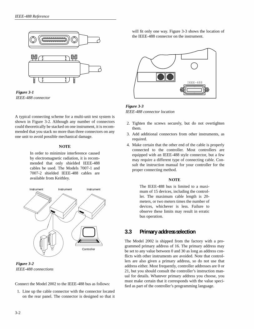
IEEE-488 Reference
3-2
A typical connecting scheme for a multi-unit test system isshown in Figure 3-2. Although any number of connectorscould theoretically be stacked on one instrument, it is recom-mended that you stack no more than three connectors on anyone unit to avoid possible mechanical damage.
NOTE
In order to minimize interference causedby electromagnetic radiation, it is recom-mended that only shielded IEEE-488cables be used. The Models 7007-1 and7007-2 shielded IEEE-488 cables areavailable from Keithley.
Connect the Model 2002 to the IEEE-488 bus as follows:
1. Line up the cable connector with the connector locatedon the rear panel. The connector is designed so that it
will fit only one way. Figure 3-3 shows the location ofthe IEEE-488 connector on the instrument.
2. Tighten the screws securely, but do not overtightenthem.
3. Add additional connectors from other instruments, asrequired.
4. Make certain that the other end of the cable is properlyconnected to the controller. Most controllers areequipped with an IEEE-488 style connector, but a fewmay require a different type of connecting cable. Con-sult the instruction manual for your controller for theproper connecting method.
NOTE
The IEEE-488 bus is limited to a maxi-mum of 15 devices, including the control-ler. The maximum cable length is 20-meters, or two meters times the number ofdevices, whichever is less. Failure toobserve these limits may result in erraticbus operation.
3.3 Primary address selection
The Model 2002 is shipped from the factory with a pro-grammed primary address of 16. The primary address maybe set to any value between 0 and 30 as long as address con-flicts with other instruments are avoided. Note that control-lers are also given a primary address, so do not use thataddress either. Most frequently, controller addresses are 0 or21, but you should consult the controller’s instruction man-ual for details. Whatever primary address you choose, youmust make certain that it corresponds with the value speci-fied as part of the controller’s programming language.
Figure 3-1IEEE-488 connector
Figure 3-2IEEE-488 connections
Instrument
Controller
Instrument Instrument
Figure 3-3IEEE-488 connector location
IEEE-488
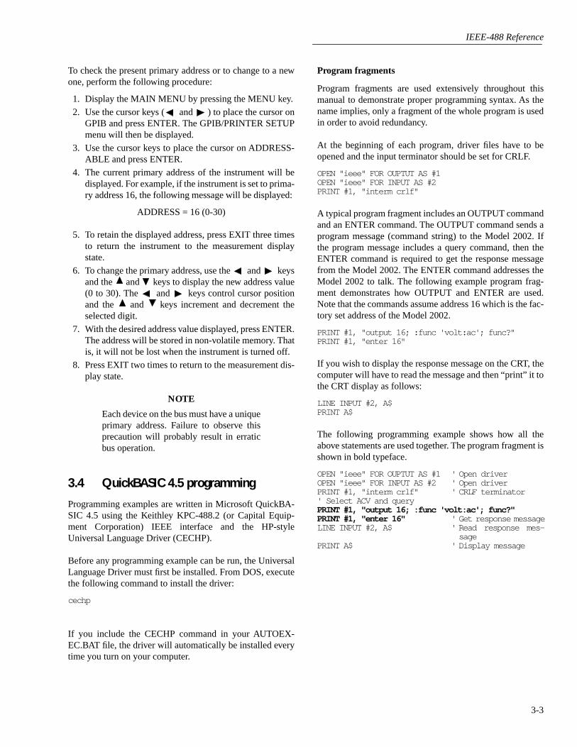
IEEE-488 Reference
3-3
To check the present primary address or to change to a newone, perform the following procedure:
1. Display the MAIN MENU by pressing the MENU key.
2. Use the cursor keys ( and ) to place the cursor onGPIB and press ENTER. The GPIB/PRINTER SETUPmenu will then be displayed.
3. Use the cursor keys to place the cursor on ADDRESS-ABLE and press ENTER.
4. The current primary address of the instrument will bedisplayed. For example, if the instrument is set to prima-ry address 16, the following message will be displayed:
ADDRESS = 16 (0-30)
5. To retain the displayed address, press EXIT three timesto return the instrument to the measurement displaystate.
6. To change the primary address, use the and keysand the and keys to display the new address value(0 to 30). The and keys control cursor positionand the and keys increment and decrement theselected digit.
7. With the desired address value displayed, press ENTER.The address will be stored in non-volatile memory. Thatis, it will not be lost when the instrument is turned off.
8. Press EXIT two times to return to the measurement dis-play state.
NOTE
Each device on the bus must have a uniqueprimary address. Failure to observe thisprecaution will probably result in erraticbus operation.
3.4 QuickBASIC 4.5 programming
Programming examples are written in Microsoft QuickBA-SIC 4.5 using the Keithley KPC-488.2 (or Capital Equip-ment Corporation) IEEE interface and the HP-styleUniversal Language Driver (CECHP).
Before any programming example can be run, the UniversalLanguage Driver must first be installed. From DOS, executethe following command to install the driver:
cechp
If you include the CECHP command in your AUTOEX-EC.BAT file, the driver will automatically be installed everytime you turn on your computer.
Program fragments
Program fragments are used extensively throughout thismanual to demonstrate proper programming syntax. As thename implies, only a fragment of the whole program is usedin order to avoid redundancy.
At the beginning of each program, driver files have to beopened and the input terminator should be set for CRLF.
OPEN "ieee" FOR OUPTUT AS #1OPEN "ieee" FOR INPUT AS #2PRINT #1, "interm crlf"
A typical program fragment includes an OUTPUT commandand an ENTER command. The OUTPUT command sends aprogram message (command string) to the Model 2002. Ifthe program message includes a query command, then theENTER command is required to get the response messagefrom the Model 2002. The ENTER command addresses theModel 2002 to talk. The following example program frag-ment demonstrates how OUTPUT and ENTER are used.Note that the commands assume address 16 which is the fac-tory set address of the Model 2002.
PRINT #1, "output 16; :func 'volt:ac'; func?"PRINT #1, "enter 16"
If you wish to display the response message on the CRT, thecomputer will have to read the message and then “print” it tothe CRT display as follows:
LINE INPUT #2, A$PRINT A$
The following programming example shows how all theabove statements are used together. The program fragment isshown in bold typeface.
OPEN "ieee" FOR OUPTUT AS #1 ' Open driverOPEN "ieee" FOR INPUT AS #2 ' Open driverPRINT #1, "interm crlf" ' CRLF terminator' Select ACV and query
PRINT #1, "output 16; :func 'volt:ac'; func?"PRINT #1, "enter 16"
' Get response messageLINE INPUT #2, A$ ' Read response mes-
sagePRINT A$ ' Display message

IEEE-488 Reference
3-4
3.5 General bus commands
General bus commands are those commands such as DCLthat have the same general meaning regardless of the instru-ment. Table 3-1 lists the general bus commands. Alsoincluded is the programming statement for each commandusing the Keithley KPC-488.2 IEEE interface and the HP-style Universal Language Driver (CECHP). Note that thecommands requiring that a primary address be specifiedassume that the address is set to 16. This is the address thatis set at the factory.
3.5.1 REN (remote enable)
The remote enable command is sent to the Model 2002 bythe controller to set up the instrument for remote operation.Generally, the instrument should be placed in the remotemode before you attempt to program it over the bus. Simplysetting REN true does not actually place the instrument in theremote state. Instead the instrument must be addressed to lis-ten after setting REN true before it goes into remote.
Note that the instrument need not be in remote to be a talker.
Program fragment
PRINT #1, "remote 16" ' Place 2002 in remote;turn on REM annunciator
Note that all front panel controls except for LOCAL (andPOWER) are inoperative while the instrument is in remote.You can restore normal front panel operation by pressing theLOCAL key.
3.5.2 IFC (interface clear)
The IFC command is sent by the controller to place theModel 2002 in the local, talker, and listener idle states. Theunit responds to the IFC command by cancelling front panelTALK or LISTEN lights, if the instrument was previouslyplaced in one of those states.
Note that this command does not affect the status of theinstrument; settings, data, and event registers are notchanged.
To send the IFC command, the controller need only set theIFC line true for a minimum of 100µsec.
Program fragment
PRINT #1, "output 16; *idn?" ' Send query commandPRINT #1, "enter 16" ' Read data; turn on
TALK annunciatorSLEEP 3 ' Wait 3 secondsPRINT #1, "abort" ' Talker idle state;
turn off TALK annun-ciator
3.5.3 LLO (local lockout)
The LLO command is used to prevent local operation of theinstrument. After the unit receives LLO, all its front panelcontrols except POWER are inoperative. In this state, press-ing LOCAL will not restore control to the front panel. TheGTL command restores control to the front panel.
Program fragment
PRINT #1, "remote 16" ' Place 2002 in remoteRINT #1, "local lockout" ' Lock out front panel
(including LOCAL key)SLEEP 6 ' Wait 6 secondsPRINT #1, "local 16" ' Restore front panel op-
eration
Table 3-1General bus commands and associated statements
Command Programming statement Effect on Model 2002
RENIFCLLOGTL
DCLSDCGETSPE, SPD
REMOTE 16ABORTLOCAL LOCKOUTLOCAL 16LOCALCLEARCLEAR 16TRIGGER 16SPOLL 16
Goes into effect when next addressed to listen.Goes into talker and listener idle states.LOCAL key locked out.Cancel remote, restore front panel operation for 2002.Cancel remote, restore front panel operation for all devices.Returns all devices to known conditions.Returns Model 2002 to known conditions.Initiates a trigger.Serial Polls the Model 2002.

IEEE-488 Reference
3-5
3.5.4 GTL (go to local)
The GTL command is used to take the instrument out of theremote state. Operation of the front panel keys will also berestored by GTL.
Program fragment
PRINT #1, "remote 16" ' Place 2002 in remoteSLEEP 3 ' Wait 3 secondsPRINT #1, "local 16" ' Take 2002 out of remote
3.5.5 DCL (device clear)
The DCL command may be used to clear the IEEE GPIBinterface and return it to a known state. Note that the DCLcommand is not an addressed command, so all instrumentsequipped to implement DCL will do so simultaneously.
When the Model 2002 receives a DCL command, it clearsthe Input Buffer and Output Queue, cancels deferred com-mands, and clears any command that prevents the processingof any other device command. A DCL does not affect instru-ment settings and stored data.
Program fragment
PRINT #1, "clear" ' Clear all devices
3.5.6 SDC (selective device clear)
The SDC command is an addressed command that performsessentially the same function as the DCL command. How-ever, since each device must be individually addressed, theSDC command provides a method to clear only selectedinstruments instead of clearing all instruments simulta-neously, as is the case with DCL.
Program fragment
PRINT #1, "clear 16" ' Clear 2002
3.5.7 GET (group execute trigger)
GET is a GPIB trigger that is used as an arm, scan and/ormeasure event to control operation. The Model 2002 will re-act to this trigger if it is the programmed control source. GETcan also be used as the pre-trigger for the reading buffer. Thecontrol source is programmed from the SCPI :TRIGger sub-system.
With the instrument programmed and waiting for a GPIBtrigger, the following program fragment will provide theGET.
Program fragment
PRINT #1, "trigger 16" ' Trigger 2002 from overthe bus
This sends IEEE-488 commands UNT UNL LISTEN 16GET. When the command is executed, the trigger event oc-curs. (The command TRIGGER just sends GET. Any otherlisteners are triggered when the command is executed.)
3.5.8 SPE, SPD (serial polling)
The serial polling sequence is used to obtain the Model 2002serial poll byte. The serial poll byte contains important infor-mation about internal functions, as described in paragraph3.7.6. Generally, the serial polling sequence is used by thecontroller to determine which of several instruments hasrequested service with the SRQ line. However, the serialpolling sequence may be performed at any time to obtain thestatus byte from the Model 2002.
Program fragment
PRINT #1, "spoll 16" ' Serial poll the 2002INPUT #2, S ' Read the serial poll bytePRINT S ' Display the decimal value of
the serial poll byte
3.6 Front panel aspects of IEEE-488 operation
The following paragraphs discuss aspects of the front panelthat are part of IEEE-488 operation, including messages, sta-tus indicators, and the LOCAL key.
3.6.1 Error and status messages
Table 2-4 summarizes the error and status messages associ-ated with IEEE-488 programming. Note that the instrumentmay be programmed to generate an SRQ, and command que-ries can be performed to check for specific error conditions.
3.6.2 IEEE-488 status indicators
The REM (remote), TALK (talk), LSTN (listen), and SRQ(service request) annunciators show the present IEEE-488status of the instrument. Each of these indicators is brieflydescribed below.
REM —
This indicator shows when the instrument is in theremote state. Note that REM does not necessarily indicatethe state of the REN line, as the instrument must beaddressed to listen with REN true before the REM indicator
IEEE-488 Reference
3-6
turns on. When the instrument is in remote, all front panelkeys except for the LOCAL key are locked out. When REMis turned off, the instrument is in the local state, and frontpanel operation is restored.
TALK —
This indicator is on when the instrument is in thetalker active state. The unit is placed in this state by address-ing it to talk with the correct MTA (My Talk Address) com-mand. TALK is off when the unit is in the talker idle state.The instrument is placed in the talker idle state by sending itan UNT (Untalk) command, addressing it to listen, or withthe IFC (Interface Clear) command.
LSTN —
This indicator is on when the Model 2002 is in thelistener active state, which is activated by addressing the in-strument to listen with the correct MLA (My Listen Address)command. Listen is off when the unit is in the listener idlestate. The unit can be placed in the listener idle state by send-ing UNL (Unlisten), addressing it to talk, or by sending IFC(Interface Clear) over the bus.
SRQ —
The instrument can be programmed to generate aservice request (SRQ) when one or more errors or conditionsoccur. When this indicator is on, a service request has beengenerated. This indicator will stay on until the serial poll byte
is read or all the conditions which caused SRQ have ceasedto exist. See paragraph 3.7.6 for details.
3.6.3 LOCAL key
The LOCAL key cancels the remote state and restores localoperation of the instrument.
Pressing LOCAL also turns off the REM indicator andreturns the display to normal if a user defined message wasdisplayed.
Note that the LOCAL key is also inoperative if the LLO(Local Lockout) command is in effect.
3.7 Status structure
The status structure for the Model 2002 is summarized inFigure 3-4. Instrument events, such as errors, are monitoredand manipulated by seven status register sets. Notice thatthese seven status register sets feed directly or indirectly intothe Status Byte Register. More detailed illustrations of theseregister sets are provided by Figures 3-5 through 3-11.

IEEE-488 Reference
3-7
Figure 3-4Model 2002 status register structure
0Se
q 1
2 3 4 5 6 7 8 9 10 11 12 13 14 15
Trig
ger
Con
ditio
nR
egis
ter
In T
rigg
er L
ayer
1
(Alw
ays
Zer
o)
0Se
q 1
2 3 4 5 6 7 8 9 10 11 12 13 14 15
Trig
ger
Tran
sitio
nFi
lter
0Se
q 1
2 3 4 5 6 7 8 9 10 11 12 13 14 15
Trig
ger
Even
tR
egis
ter
0Se
q 1
2 3 4 5 6 7 8 9 10 11 12 13 14 15
Trig
ger
Even
t E
nabl
eR
egis
ter
& & & & & & & & & & & & & & & &
Logi
cal
OR
0 2 3 5 6 Cal7 9 10 11 12 13
14
15
Que
stio
nabl
eC
ondi
tion
Reg
iste
r
(Alw
ays
Zer
o)
0 2 3 5 6 7 9 10 11 12 13
14
15
Que
stio
nabl
eTr
ansi
tion
Filte
r
0 2 3 5 6 7 9 10 11 12 13
14
15
Que
stio
nabl
eEv
ent
Reg
iste
r
01
11
1 2 3 5 6 7 9 10 11 12 13
14
15
Que
stio
nabl
eEv
ent
Enab
leR
egis
ter
& & & & & & & & & & & & & & & &
Logi
cal
OR
Set 3
Trig
Arm 7 8 Idle
11 12 13 15
Ope
ratio
nC
ondi
tion
Reg
iste
r
(Alw
ays
Zer
o)
Set 3 7 8 Idle
11 12 13 15
Ope
ratio
nTr
ansi
tion
Filte
r
Set 3 7 8 Idle
11 12 13 15
Ope
ratio
nEv
ent
Reg
iste
r
Set 3 7 8 Idle
11 12 13 15
Ope
ratio
nEv
ent
Ena
ble
Reg
iste
r& & & & & & & & & & & & & & & &
Logi
cal
OR
Settl
ing
Wai
ting
in T
rigg
er L
ayer
Wai
ting
in a
n A
rm L
ayer Id
le
0Se
q 1
2 3 4 5 6 7 8 9 10 11 12 13 14 15Arm
Con
ditio
nR
egis
ter
In a
n A
rm L
ayer
(Alw
ays
Zer
o)
0Se
q 1
2 3 4 5 6 7 8 9 10 11 12 13 14 15Arm
Tran
sitio
nFi
lter
0Se
q 1
2 3 4 5 6 7 8 9 10 11 12 13 14 15Arm
Even
tR
egis
ter
0Se
q 1
2 3 4 5 6 7 8 9 10 11 12 13 14 15Arm
Even
t E
nabl
eR
egis
ter
& & & & & & & & & & & & & & & &
Logi
cal
OR
EAV
QSB
MA
VES
BR
QS/
MSS
OSB
Stat
usB
yte
Reg
iste
r
1EA
VQ
SBM
AV
ESB 6
OSB
Serv
ice
Req
uest
Enab
leR
egis
ter
& & & & & & &
Logi
cal
OR
*STB
?*S
RE
*SR
E?
Mas
ter
Sum
mar
y St
atus
(MSS
)
MSB
= M
easu
rem
ent S
umm
ary
Bit
EAV
= E
rror
Ava
ilabl
eQ
SB =
Que
stio
nabl
e Su
mm
ary
Bit
MA
V =
Mes
sage
Ava
ilabl
eES
B =
Eve
nt S
umm
ary
Bit
RQ
S/M
SS =
Req
uest
for
Serv
ice/
Mas
ter
Sum
mar
y St
aus
OSB
= O
pera
tion
Sum
mar
y B
it
0La
y 1
Lay
23 4 5 6 7 8 9 10 11 12 13 15
Sequ
ence
Con
ditio
nR
egis
ter
(Alw
ays
Zer
o)
0 3 4 5 6 7 8 9 10 11 12 13 15
Sequ
ence
Tran
sitio
nFi
lter
0 3 4 5 6 7 8 9 10 11 12 13 15
Sequ
ence
Even
tR
egis
ter
0 3 4 5 6 7 8 9 10 11 12 13 15
Sequ
ence
Even
t E
nabl
eR
egis
ter
& & & & & & & & & & & & & & & &
Logi
cal
OR
14
In A
rm L
ayer
1La
y 1
Lay
2La
y 1
Lay
2La
y 1
Lay
2
1414
14
In A
rm L
ayer
2
Erro
r Q
ueue
Out
put Q
ueue
Trig
Trig
Trig
Arm
Arm
Arm
Not
e :
RQ
S bi
t is
in s
eria
l pol
l byt
e,
M
SS b
it is
in *
STB
? re
spon
se.
1
1414
OPC
QY
ED
DE
EXE
CM
EU
RQ
PON
8 9 8 11 12 13 15
Stan
dard
Even
tSt
atus
Reg
iste
r
8 9 8 11 12 13 15
Stan
dard
Even
tSt
atus
Ena
ble
Reg
iste
r& & & & & & & & & & & & & & & &
Logi
cal
OR
(Alw
ays
Zer
o)
Ope
ratio
n C
ompl
ete
Que
ry E
rror
Dev
ice
Spec
ific
Erro
rEx
ecut
ion
Erro
rC
omm
and
Erro
rU
ser
Req
uest
Pow
er O
n
OPC
QY
ED
DE
EXE
CM
EU
RQ
PON
*ESR
?*E
SE*E
SE?
MSB
MSB
Cal
ibra
ting
Cal
Cal
Cal
Cal
BPT 12 13 14 15
(Alw
ays
Zer
o)
12 13 14 15
Mea
sure
men
tTr
ansi
tion
Filte
r
12 13 14 15
Mea
sure
men
tEv
ent
Reg
iste
r
12 13 14 15
Mea
sure
men
tEv
ent
Enab
leR
egis
ter
& & & & & & & & & & & & & & & &
Logi
cal
OR
Mea
sure
men
tC
ondi
tion
Reg
iste
r
RO
FLL
1H
L1LL
2H
L2R
AV
BA
VB
HF
BFL
RO
FLL
1H
L1LL
2H
L2R
AV
BA
VB
HF
BFL
RO
FLL
1H
L1LL
2H
L2R
AV
BA
VB
HF
BFL
RO
FLL
1H
L1LL
2H
L2R
AV
BA
VB
HF
BFL
Rea
ding
Ove
rfol
wLo
w L
imit
1
Low
Lim
it 2
Hig
h Li
mit
1
Hig
h Li
mit
2R
eadi
ng A
vaila
ble
Buf
fer
Ava
ilabl
eB
uffe
r H
alf F
ull
Buf
fer
Full
Buf
fer
Pret
rigg
ered
BPT
BPT
BPT
11
Cal
Cal
Cal
Cal
ibra
tion
Sum
mar
y
Com
man
d W
arni
ngW
arn
War
nW
arn
War
n
2 4
22
2
44
4
Tem
pera
ture
Sum
mar
yTe
mp
Tem
pTe
mp
Tem
p
6 10
66
6
1010
10
99
99

IEEE-488 Reference
3-8
3.7.1 Condition registers
As shown in the illustrations, all status register sets, exceptthe standard event status register set, have a condition regis-ter. A condition register is a real-time read-only register thatconstantly updates to reflect the current operating conditionsof the instrument. For example, while a calculation is beingperformed, bit B9 (Calc) of the Operation Condition Regis-ter is set. When the calculation is completed, bit B9 clears.
The :CONDition? query commands in the STATus Sub-system are used to read the condition registers. See para-graph 3.20 for details.
3.7.2 Transition filters
As shown in the illustrations, all status register sets, exceptthe standard event status register set, have a transition filter.A transition filter is made up of two registers that are pro-grammed by the user. It is used to specify which transition (0to 1, or 1 to 0) in the corresponding condition register will setthe corresponding bit in the event register.
A filter can be programmed for positive transitions (PTR),negative transitions (NTR) or both. When an event is pro-grammed for a positive transition, the corresponding bit inthe event register sets when the corresponding bit in the con-dition register changes for 0 to 1. Conversely, when pro-grammed for a negative transition, the bit in the event registersets when the corresponding bit in the condition registerchanges from 1 to 0.
The :PTR and :NTR commands in the Status Subsystem areused to set or clear the individual bits of the transition filterregisters, while the :PTR? and :NTR? query commands areused to read the registers (see paragraph 3.20 for details).Reading a transition filter register does not affect its bitpattern.
The following operations set (1) all bits of all PTR registersand clear (0) all bits of all NTR registers:
• Cycling power
• Sending :STATus:PRESet
3.7.3 Event registers
As shown in the illustrations, each status register set has anevent register. An event register is a latched, read-only regis-ter whose bits are set by the corresponding condition registerand transition filter. Once a bit in an event register is set, itremains set (latched) until the register is cleared by a specific
clearing operation. The bits of an event register are logicallyANDed with the bits of the corresponding enable registerand applied to an OR gate. The output of the OR gate isapplied to another register set or to the Status Byte Register.
The *ESR? Common Command is used to read the StandardEvent Register (see paragraph 3.10.3). All other event regis-ters are read using the [:EVENT]? query commands in theSTATus Subsystem (see paragraph 3.20).
An event register is cleared when it is read. The followingoperations clear all event registers:
• Cycling power
• Sending *CLS
3.7.4 Enable registers
As shown in the illustrations, each status register set has anenable register. An enable register is programmed by the userand serves as a mask for the corresponding event register. Anevent bit is masked when the corresponding bit in the enableregister is cleared (0). When masked, a set bit in an event reg-ister cannot set a bit in a following register set or in the StatusByte Register (1 AND 0 = 0).
To use the Status Byte Register to detect events (i.e. serialpoll), you must unmask the events by setting (1) the appro-priate bits of the enable registers.
The Standard Event Status Enable Register is programmedand queried using the *ESE and *ESE? Common Com-mands respectively (see paragraph 3.10.2). All other enableregisters are programmed and queried using the :ENABleand :ENABle? commands in the STATus Subsystem (seeparagraph 3.20).
An enable register is not cleared when it is read. The Enableregisters are affected by the following operations:
• Cycling power – Clears all enable registers
• :STATus:PRESet clears the following enable registers:
Operation Event Enable Register
Questionable Event Enable Register
Measurement Event Enable Register
• :STATus:PRESet sets all bits of the following enableregisters:
Trigger Event Enable Register
Arm Event Enable Register
Sequence Event Enable Register
• *ESE 0 – Clears the Standard Event Status EnableRegister.

IEEE-488 Reference
3-9
Figure 3-5Standard event status
* ESR ? PON(B7)
URQ(B6)
CME(B5)
EXE(B4)
DDE(B3)
QYE(B2) (B1) (B0)
OR
Standard EventStatus Register
Standard EventStatus EnableRegister
PON = Power OnURQ = User RequestCME = Command ErrorEXE = Execution ErrorDDE = Device-Dependent ErrorQYE = Query ErrorOPC = Operation Complete
& = Logical ANDOR = Logical OR
&
&
&
&
&
OPC
&
&
PON(B7)
URQ(B6)
CME(B5)
EXE(B4)
DDE(B3)
QYE(B2) (B1) (B0)
OPC* ESE* ESE ?
To Event SummaryBit (ESB) ofStatus ByteRegister (SeeFigure 3-12).
(B15 - B8)
(B15 - B8)

IEEE-488 Reference
3-10
Figure 3-6Operation event status
(B15 - B11)
Idle
(B10) (B9) (B8) (B7)
Arm
(B6)
Trig
(B5)
Meas
(B4) (B3)
OR
Idle = IdleArm = Waiting in an ArmLayerTrig = Waiting in Trigger LayerSet = SettlingCal = Calibrating
& = Logical ANDOR = Logical OR
(B2) (B1) (B0)
(B15 - B11)Idle
(B10) (B9) (B8) (B7) Arm(B6)
Trig(B5)
Meas(B4) (B3) (B2) (B1) (B0)
Operation EventRegister
(B15 - B11)Idle
(B10) (B9) (B8) (B7)Arm(B6)
Trig(B5)
Meas (B4) (B3) (B2) (B1) (B0)
Operation EventEnable Register
&
To OperationSummary Bit(OSB) of StatusByte Register.(See Figure 3-12).
&
&
&
PTR = Positive Transition FilterNTR = Negative Transition Filter
PTR TransitionNTR Filter
(B15 - B11)Idle
(B10) (B9) (B8) (B7)Arm(B6)
Trig(B5)
Meas(B4) (B3) (B2) (B1) (B0)
Operation ConditionRegister
From OR'ed summaryof Trigger Event Status(see Figure 3-9)
From OR'ed summary ofArm Event Status (seeFigure 3-7).
Cal
Cal
Cal
&
Cal
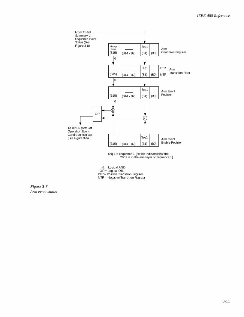
IEEE-488 Reference
3-11
Figure 3-7Arm event status
(B14 - B2)(B15) (B1) (B0)
OR
ArmCondition Register
Arm EventEnable Register
Seq 1 = Sequence 1 (Set bit indicates that the 2001 is in the arm layer of Sequence 1)
& = Logical AND OR = Logical ORPTR = Positive Transition RegisterNTR = Negative Transition Register
&
&
0
Seq1
(B14 - B2)(B15) (B1) (B0)
0
Seq1
(B14 - B2)(B15) (B1) (B0)
0
AlwaysZero
Seq1
PTR
NTR
ArmTransition Filter
Arm EventRegister
(B14 - B2)(B15) (B1) (B0)
Seq1
To Bit B6 (Arm) ofOperation EventCondition Register(See Figure 3-6).
From ORedSummary ofSequence EventStatus (SeeFigure 3-8).

IEEE-488 Reference
3-12
Figure 3-8Sequence event status
(B14 - B3)(B15) (B2) (B1) (B0)
OR
SequenceCondition Register
Sequence EventEnable Register
Lay1 = Layer 1 (Set bit indicates that 2002 is in arm layer 1).Lay2 = Layer 2 (Set bit indicates that 2002 is in arm layer 2).
& = Logical AND OR = Logical ORPTR = Positive Transition RegisterNTR = Negative Transition Register
&
&
&
0
Lay2 Lay1
(B14 - B3)(B15) (B2) (B1) (B0)
0
Lay2 Lay1
(B14 - B3)(B15) (B2) (B1) (B0)
0
AlwaysZero
Lay2 Lay1
PTR
NTR
SequenceTransition Filter
Sequence EventRegister
(B14 - B3)(B15) (B2) (B1) (B0)
Lay2 Lay1
To Sequence 1 Bit(Seq 1) of ArmEvent ConditionRegister (SeeFigure 3-7).
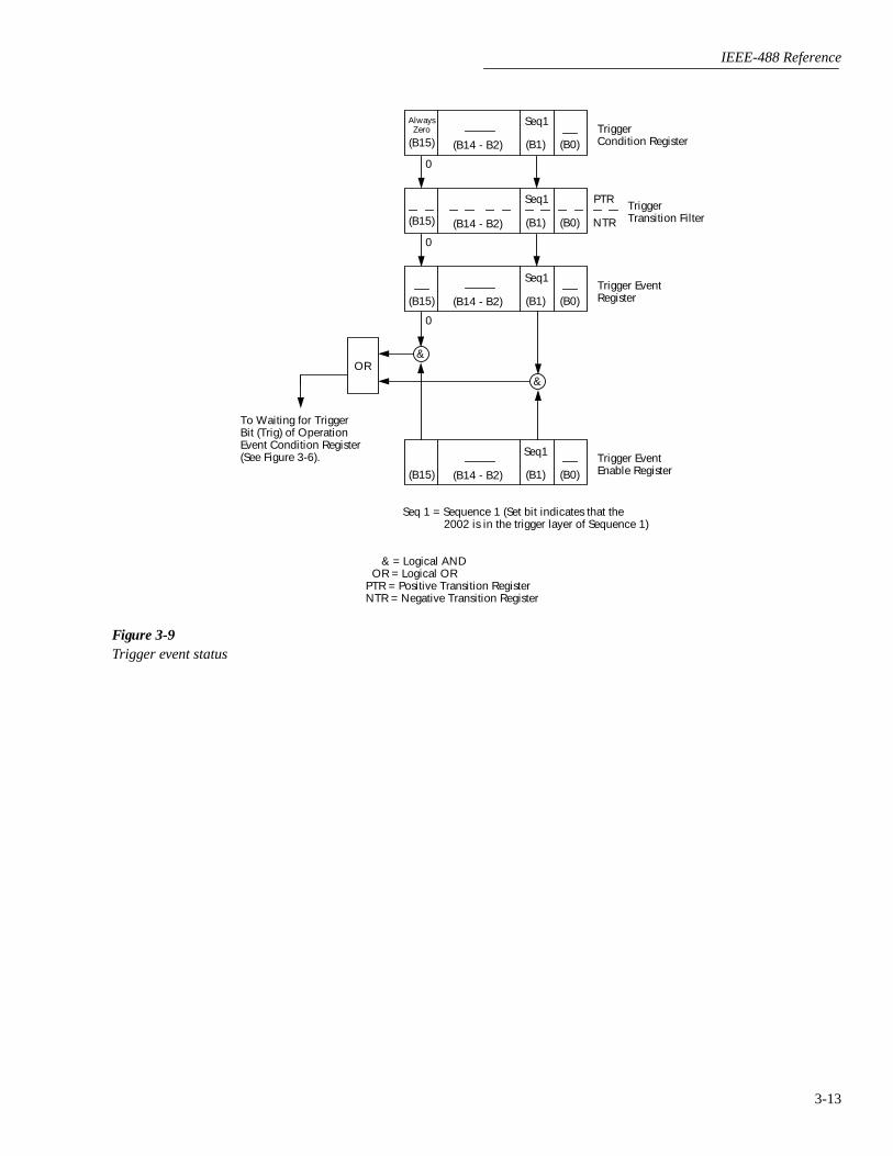
IEEE-488 Reference
3-13
Figure 3-9Trigger event status
(B14 - B2)(B15) (B1) (B0)
OR
TriggerCondition Register
Trigger EventEnable Register
Seq 1 = Sequence 1 (Set bit indicates that the 2002 is in the trigger layer of Sequence 1)
& = Logical AND OR = Logical ORPTR = Positive Transition RegisterNTR = Negative Transition Register
&
&
0
Seq1
(B14 - B2)(B15) (B1) (B0)
0
Seq1
(B14 - B2)(B15) (B1) (B0)
0
AlwaysZero
Seq1
PTR
NTR
TriggerTransition Filter
Trigger EventRegister
(B14 - B2)(B15) (B1) (B0)
Seq1
To Waiting for TriggerBit (Trig) of OperationEvent Condition Register(See Figure 3-6).

IEEE-488 Reference
3-14
Figure 3-10Measurement event status
(B15 - B12) (B10) (B9) (B8) (B7) (B6)
RAV
(B5) (B4) (B3)
OR
BFL = Buffer Full BHF = Buffer Half Full BAV = Buffer Available
& = Logical ANDOR = Logical OR
(B2)
LL1
(B1) (B0)
(B15 - B12) (B10) (B9)BHF(B8)
BAV(B7) (B6)
RAV(B5) (B4) (B3) (B2)
LL1(B1) (B0)
Measurement EventRegister
(B15 - B12)
Measurement EventEnableRegister
To MeasurementSummary Bit(MSB) of StatusByte Register.(See Figure 3-12)
&
&
PTR = Positive Transition FilterNTR = Negative Transition Filter
PTR Measurement
NTR Transition Filter
(B15 - B12) (B10) (B9) (B8) (B7) (B6)RAV(B5) (B4) (B3) (B2)
LL1(B1) (B0)
MeasurementCondition Register
BFL HL2 HL1 ROF
BFL HL2 HL1 ROF
BFL HL2 ROF
&
&
&
&
BHF BAV LL2
BHF BAV LL2
LL2 HL1
&
&
&
(B10) (B9)BHF(B8)
BAV(B7) (B6)
RAV(B5) (B4) (B3) (B2)
LL1(B1) (B0)
BFL HL2 ROFLL2 HL1
RAV = Reading Available HL2 = High Limit 2 LL2 = Low Limit 2
HL1 = High Limit 1LL1 = Low Limit 1ROF = Reading Overflow
BPT(B11)
BPT
(B11)
BPT(B11)
&
BPT(B11)
BPT = Buffer Pretriggered

IEEE-488 Reference
3-15
Figure 3-11Questionable event status
(B13 - B9)(B14) (B8)(B15)
OR
QuestionableCondition Register
Questionable EventEnable Register
Warn = Command Warning Cal = Calibration SummaryTemp = Temperature Summary
& = Logical AND OR = Logical OR PTR = Positive Transition Register NTR = Negative Transition Register
&
&
&
0
(B13 - B9)(B14) (B8)(B15)
0
Cal
(B13 - B9)(B14) (B8)(B15)
0
Warn Cal
PTR
NTR
QuestionableTransition Filter
Questionable EventRegister
(B13 - B9)(B14) (B8)(B15)
To QuestionableSummary Bit(QSB) of StatusByte Register.
(B7 - B5)
(B7 - B5)
(B7 - B5)
(B7 - B5)
Warn Cal
0
Warn Cal
&
(B4)
Temp
(B4)
Temp
(B4)
Temp
(B3 - B0)
(B3 - B0)
(B3 - B0)
(B3 - B0)(B4)
Temp
&

IEEE-488 Reference
3-16
3.7.5 Queues
The Model 2002 uses two queues; the Output Queue and theError Queue. The queues are first-in first-out (FIFO) regis-ters. The Output Queue is used to hold readings and responsemessages, and the Error Queue is used to hold error mes-sages and status messages. The Model 2002 status model(Figure 3-4) shows how the two queues are structured withthe other registers.
Output Queue —
The Output Queue is used to hold data thatpertains to the normal operation of the instrument. For exam-ple, when a query command is sent, the response message isplaced in the Output Queue.
When data is placed in the Output Queue, the MessageAvailable (MAV) bit in the Status Byte Register sets. A datamessage is cleared from the Output Queue when it is read.The Output Queue is considered cleared when it is empty. Anempty Output Queue clears the MAV bit in the Status ByteRegister.
A message from the Output Queue is read by addressing theModel 2002 to talk after the appropriate query is sent.
Error Queue —
The Error Queue is used to hold error mes-sages and status messages. When an error or status eventoccurs, a message that defines the error/status is placed in theError Queue. This queue will hold up to 10 messages.
When a message is placed in the Error Queue, the ErrorAvailable (EAV) bit in the Status Byte Register is set. Anerror message is cleared from the Error/Status Queue whenit is read. The Error Queue is considered cleared when it isempty. An empty Error Queue clears the EAV bit in the Sta-tus Byte Register. An error message from the Error Queue isread by sending either of the following SCPI query com-mands and then addressing the Model 2002 to talk:
:SYSTem:ERRor?:STATus:QUEue?
Refer to paragraphs 3.20.7 (:STATus:QUEue?) and 3.21.5(:SYSTem:ERRor?) for complete information on readingerror messages.
3.7.6 Status byte and service request (SRQ)
Service request is controlled by two 8-bit registers; the StatusByte Register and the Service Request Enable Register. Thestructure of these registers is shown in Figure 3-12.
Status Byte Register —
The summary messages from thestatus registers and queues are used to set or clear the appro-priate bits (B0, B2, B3, B4, B5 and B7) of the Status ByteRegister. These bits do not latch and their states (0 or 1) aresolely dependent on the summary messages (0 or 1). Forexample, if the Standard Event Status Register is read, itsregister will clear. As a result, its summary message willreset to 0, which in turn will clear the ESB bit in the StatusByte Register.
Bit B6 in the Status Byte Register is either:
• The Master Summary Status (MSS) bit, sent inresponse to the *STB? command, indicates the status ofany set bits with corresponding enable bits set.
• The Request for Service (RQS) bit, sent in response toa serial poll, indicates which device was requesting ser-vice by pulling on the SRQ line.
For description of the other bits in the Status Byte Register,refer to paragraph 3.10.12.
The IEEE-488.2 standard uses the following common querycommand to read the Status Byte Register:
*STB?
When reading the Status Byte Register using the *STB?command, bit B6 is called the MSS bit. None of the bits inthe Status Byte Register are cleared when using the *STB?command to read it.
The IEEE-488.1 standard has a serial poll sequence that alsoreads the Status Byte Register and is better suited to detect aservice request (SRQ). When using the serial poll, bit B6 iscalled the RQS bit. Serial polling causes bit B6 (RQS) toreset. Serial polling is discussed in more detail later in thisparagraph (see “Serial Poll and SRQ”).
Any of the following operations clear all bits of the StatusByte Register:
• Cycling power.
• Sending the *CLS common command.
NOTE
The MAV bit may or may not be cleared.
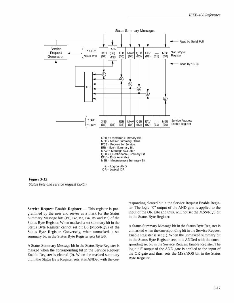
IEEE-488 Reference
3-17
Service Request Enable Register — This register is pro-grammed by the user and serves as a mask for the StatusSummary Message bits (B0, B2, B3, B4, B5 and B7) of theStatus Byte Register. When masked, a set summary bit in theStatus Byte Register cannot set bit B6 (MSS/RQS) of theStatus Byte Register. Conversely, when unmasked, a setsummary bit in the Status Byte Register sets bit B6.
A Status Summary Message bit in the Status Byte Register ismasked when the corresponding bit in the Service RequestEnable Register is cleared (0). When the masked summarybit in the Status Byte Register sets, it is ANDed with the cor-
Figure 3-12Status byte and service request (SRQ)
Status Summary Messages
* STB?
Serial PollOSB(B7)
RQS(B6)MSS
ESB(B5)
MAV(B4)
QSB(B3)
EAV(B2) (B1) (B0)
OR
* SRE
* SRE?
Status ByteRegister
Service RequestEnable Register
OSB = Operation Summary BitMSS = Master Summary StatusRQS = Request for ServiceESB = Event Summary BitMAV = Message AvailableQSB = Questionable Summary BitEAV = Error AvailableMSB = Measurement Summary Bit
& = Logical ANDOR = Logical OR
OSB(B7) (B6)
ESB(B5)
MAV(B4)
QSB(B3)
EAV(B2) (B1) (B0)
&
&
&
&
&
MSB
MSB
&
ServiceRequest
Generation
Read by Serial Poll
Read by *STB?
responding cleared bit in the Service Request Enable Regis-ter. The logic “0” output of the AND gate is applied to theinput of the OR gate and thus, will not set the MSS/RQS bitin the Status Byte Register.
A Status Summary Message bit in the Status Byte Register isunmasked when the corresponding bit in the Service RequestEnable Register is set (1). When the unmasked summary bitin the Status Byte Register sets, it is ANDed with the corre-sponding set bit in the Service Request Enable Register. Thelogic “1” output of the AND gate is applied to the input ofthe OR gate and thus, sets the MSS/RQS bit in the StatusByte Register.

IEEE-488 Reference
3-18
The individual bits of the Service Request Enable Registercan be set or cleared by using the following common com-mand (see paragraph 3.10.11 for details):
*SRE <NRf>
The Service Request Enable Register can be read using thefollowing common query command (see paragraph 3.10.11for details):
*SRE?
The Service Request Enable Register is not cleared when itis read using the *SRE? query command. The ServiceRequest Enable Register clears when power is cycled or aparameter (n) value of zero is sent with the *SRE command(*SRE 0).
Serial poll and SRQ
Any enabled event summary bit that goes from 0 to 1 will setRQS and generate a service request (SRQ). The user’s testprogram can periodically read the Status Byte Register tocheck to see if a service request (SRQ) has occurred andwhat caused it. In the event of an SRQ, the program can, forexample, branch to an appropriate subroutine that will ser-vice the request. Typically, service requests (SRQs) are man-aged by the serial poll sequence of the Model 2002. If anSRQ does not occur, bit B6 (RQS) of the Status Byte Regis-ter will remain cleared and the program will simply proceednormally after the serial poll is performed. If an SRQ doesoccur, bit B6 of the Status Byte Register will set and the pro-gram can branch to a service subroutine when the SRQ is de-tected by the serial poll.
The serial poll automatically resets RQS of the Status ByteRegister. This will allow subsequent serial polls to monitorBit 6 for an SRQ occurrence generated by other event types.After a serial poll, the same event can cause another SRQ,even if the event register which caused the first SRQ has notbeen cleared.
A serial poll clears RQS but does not clear MSS. The MSSbit will stay set until all Status Byte event summary bits arecleared.
The following QuickBASIC 4.5 program (using the KPC-488.2 interface and the CECHP driver) demonstrates howserial poll can be used to detect an SRQ.
CLSOPEN "ieee" FOR OUTPUT AS #1OPEN "ieee" FOR INPUT AS #2PRINT #1, "output 16; *cls" ' Clear Status Byte
RegisterPRINT #1, "output 16; *ese 32" ' Unmask command
errorsPRINT #1, "output 16; *sre 32" ' Unmask event sum-
mary messagePRINT #1, "output 16; *ese" ' Error - missing
parameterSLEEP 1PRINT #1, "SPOLL 16" ' Serial poll 2002INPUT #2, S ' Read Status Byte
RegisterS = S OR 191 ' OR register with a
maskIF S = 255 THENGOSUB srq ' Go to subroutine
to acknowledgeSRQ
END IFPRINTEND
srq:PRINT "SRQ Has Occurred – RQS (bit B6) is set (1)"RETURN
3.8 Trigger model (IEEE-488 operation)
The following information describes the operation process ofthe Model 2002 over the IEEE-488 bus. The flowchart inFigure 3-13, which summarizes operation over the bus, iscalled the Trigger model. It is called the trigger modelbecause operation is controlled by SCPI commands from theTrigger subsystem (see paragraph 3.23. Notice that key SCPIcommands are included in the trigger model.
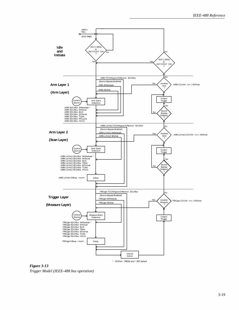
IEEE-488 Reference
3-19
Figure 3-13Trigger Model (IEEE-488 bus operation)
Arm Layer 1
(Arm Layer)
Arm EventDetection
ControlSource
No
Idleand
Initiate
No
Yes
:ARM:SOURce IMMediate *:ARM:SOURce MANual:ARM:SOURce BUS:ARM:SOURce EXTernal:ARM:SOURce TLINk:ARM:SOURce RTCLock:ARM:SOURce HOLD
:ARM:TCONfigure:DIRection SOURce
(Source Bypass Enabled)
:ARM:IMMediate
:ARM:SIGNal
AnotherArm
?
OutputTrigger
:ARM:COUNt <n> | INFinite
No
Yes
Arm Layer 2
(Scan Layer)
Scan EventDetection
No
Yes
:ARM:LAYer2:SOURce IMMediate *:ARM:LAYer2:SOURce MANual:ARM:LAYer2:SOURce BUS:ARM:LAYer2:SOURce TIMer:ARM:LAYer2:SOURce EXTernal:ARM:LAYer2:SOURce TLINk:ARM:LAYer2:SOURce HOLD
:ARM:LAYer2:TCONfigure:DIRection SOURce
(Source Bypass Enabled)
:ARM:LAYer2:IMMediate
:ARM:LAYer2:SIGNalAnother
Scan?
:ARM:LAYer2:COUNt <n> | INFinite
No
Yes
Delay:ARM:LAYer2:DELay <num>
Measure EventDetection
No
Yes
:TRIGger:SOURce IMMediate *:TRIGger:SOURce MANual:TRIGger:SOURce BUS:TRIGger:SOURce TIMer:TRIGger:SOURce EXTernal:TRIGger:SOURce TLINk:TRIGger:SOURce HOLD
:TRIGger:TCONfigure:DIRection SOURce
(Source Bypass Enabled)
:TRIGger:IMMediate
:TRIGger:SIGNal:TRIGger:COUNt <n> | INFinite
:TRIGger:DELay <num>
DeviceAction
OutputTrigger
ControlSource
OutputTrigger
Delay
ControlSource
Trigger Layer
(Measure Layer)
SourceBypassEnabled
?
SourceBypassEnabled
?
AnotherMeasure
?
Yes
:INIT [:IMM]or
:INIT:CONT ON?
Yes
NoYes
:INIT [:IMM]or
:INIT:CONT ON?
Yes
:ABOrt*RCL
:SYST:PRES
* : SYSTem : PRESet and * RST default
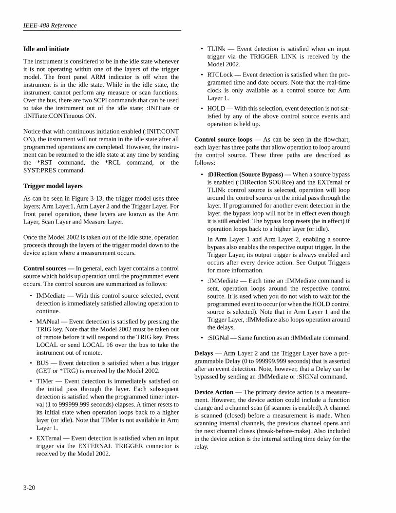
IEEE-488 Reference
3-20
Idle and initiate
The instrument is considered to be in the idle state wheneverit is not operating within one of the layers of the triggermodel. The front panel ARM indicator is off when theinstrument is in the idle state. While in the idle state, theinstrument cannot perform any measure or scan functions.Over the bus, there are two SCPI commands that can be usedto take the instrument out of the idle state; :INITiate or:INITiate:CONTinuous ON.
Notice that with continuous initiation enabled (:INIT:CONTON), the instrument will not remain in the idle state after allprogrammed operations are completed. However, the instru-ment can be returned to the idle state at any time by sendingthe *RST command, the *RCL command, or theSYST:PRES command.
Trigger model layers
As can be seen in Figure 3-13, the trigger model uses threelayers; Arm Layer1, Arm Layer 2 and the Trigger Layer. Forfront panel operation, these layers are known as the ArmLayer, Scan Layer and Measure Layer.
Once the Model 2002 is taken out of the idle state, operationproceeds through the layers of the trigger model down to thedevice action where a measurement occurs.
Control sources — In general, each layer contains a controlsource which holds up operation until the programmed eventoccurs. The control sources are summarized as follows:
• IMMediate — With this control source selected, eventdetection is immediately satisfied allowing operation tocontinue.
• MANual — Event detection is satisfied by pressing theTRIG key. Note that the Model 2002 must be taken outof remote before it will respond to the TRIG key. PressLOCAL or send LOCAL 16 over the bus to take theinstrument out of remote.
• BUS — Event detection is satisfied when a bus trigger(GET or *TRG) is received by the Model 2002.
• TIMer — Event detection is immediately satisfied onthe initial pass through the layer. Each subsequentdetection is satisfied when the programmed timer inter-val (1 to 999999.999 seconds) elapses. A timer resets toits initial state when operation loops back to a higherlayer (or idle). Note that TIMer is not available in ArmLayer 1.
• EXTernal — Event detection is satisfied when an inputtrigger via the EXTERNAL TRIGGER connector isreceived by the Model 2002.
• TLINk — Event detection is satisfied when an inputtrigger via the TRIGGER LINK is received by theModel 2002.
• RTCLock — Event detection is satisfied when the pro-grammed time and date occurs. Note that the real-timeclock is only available as a control source for ArmLayer 1.
• HOLD — With this selection, event detection is not sat-isfied by any of the above control source events andoperation is held up.
Control source loops — As can be seen in the flowchart,each layer has three paths that allow operation to loop aroundthe control source. These three paths are described asfollows:
• :DIRection (Source Bypass) — When a source bypassis enabled (:DIRection SOURce) and the EXTernal orTLINk control source is selected, operation will looparound the control source on the initial pass through thelayer. If programmed for another event detection in thelayer, the bypass loop will not be in effect even thoughit is still enabled. The bypass loop resets (be in effect) ifoperation loops back to a higher layer (or idle).
In Arm Layer 1 and Arm Layer 2, enabling a sourcebypass also enables the respective output trigger. In theTrigger Layer, its output trigger is always enabled andoccurs after every device action. See Output Triggersfor more information.
• :IMMediate — Each time an :IMMediate command issent, operation loops around the respective controlsource. It is used when you do not wish to wait for theprogrammed event to occur (or when the HOLD controlsource is selected). Note that in Arm Layer 1 and theTrigger Layer, :IMMediate also loops operation aroundthe delays.
• :SIGNal — Same function as an :IMMediate command.
Delays — Arm Layer 2 and the Trigger Layer have a pro-grammable Delay (0 to 999999.999 seconds) that is assertedafter an event detection. Note, however, that a Delay can bebypassed by sending an :IMMediate or :SIGNal command.
Device Action — The primary device action is a measure-ment. However, the device action could include a functionchange and a channel scan (if scanner is enabled). A channelis scanned (closed) before a measurement is made. Whenscanning internal channels, the previous channel opens andthe next channel closes (break-before-make). Also includedin the device action is the internal settling time delay for therelay.
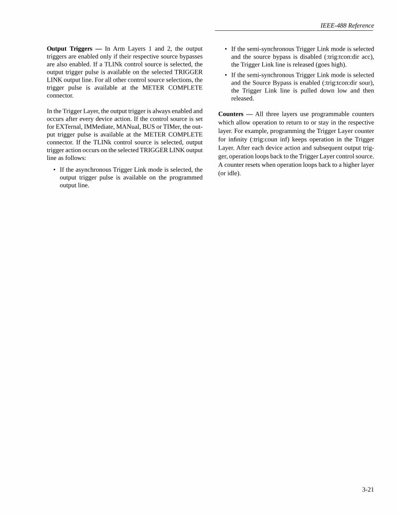
IEEE-488 Reference
3-21
Output Triggers — In Arm Layers 1 and 2, the outputtriggers are enabled only if their respective source bypassesare also enabled. If a TLINk control source is selected, theoutput trigger pulse is available on the selected TRIGGERLINK output line. For all other control source selections, thetrigger pulse is available at the METER COMPLETEconnector.
In the Trigger Layer, the output trigger is always enabled andoccurs after every device action. If the control source is setfor EXTernal, IMMediate, MANual, BUS or TIMer, the out-put trigger pulse is available at the METER COMPLETEconnector. If the TLINk control source is selected, outputtrigger action occurs on the selected TRIGGER LINK outputline as follows:
• If the asynchronous Trigger Link mode is selected, theoutput trigger pulse is available on the programmedoutput line.
• If the semi-synchronous Trigger Link mode is selectedand the source bypass is disabled (:trig:tcon:dir acc),the Trigger Link line is released (goes high).
• If the semi-synchronous Trigger Link mode is selectedand the Source Bypass is enabled (:trig:tcon:dir sour),the Trigger Link line is pulled down low and thenreleased.
Counters — All three layers use programmable counterswhich allow operation to return to or stay in the respectivelayer. For example, programming the Trigger Layer counterfor infinity (:trig:coun inf) keeps operation in the TriggerLayer. After each device action and subsequent output trig-ger, operation loops back to the Trigger Layer control source.A counter resets when operation loops back to a higher layer(or idle).

IEEE-488 Reference
3-22

IEEE-488 Reference
3-23
3.9 Programming syntax
The following information covers syntax for both common commands and SCPI commands.For information not covered here, refer to the IEEE-488.2 and SCPI standards.
Command words
Program messages are made up of one or more command words.
1.
Commands and command parameters:
Common commands and SCPI commands mayor may not use a parameter. Examples:
*SAV <NRf> Parameter (NRf) required.*RST No parameter used.:INITiate:CONTinuous <b> Parameter (<b>) required.:SYSTem:PRESet No parameter used.
Note that there must be at least one space between the command word and the parameter.
Brackets [ ]:
There are command words that are enclosed in brackets ([]). These bracketsare used to denote an optional command word that does not need to be included in the pro-gram message. For example:
:INITiate[:IMMediate]
The brackets indicate that :IMMediate is implied (optional) and does not have to be used.Thus, the above command can be sent in one of two ways:
:INITiate or :INITiate:IMMediate
Notice that the optional command is used without the brackets.
Do not include the brack-ets when using an optional command word.
Parameter types:
Some of the more common parameter types are explained as follows:
<b> Boolean: Used to enable or disable an instrument operation. 0 or OFF dis-ables the operation, and 1 or ON enables the operation. Example:
:CURRent:AC:RANGe:AUTO ON Enable auto-ranging.
AC|DC Explicit: This is an example of two explicit parameters to choose from; ACor DC. Example:
:CURRent:AC:COUPling AC Select AC coupling
<name> Name parameter: Select a parameter name from a listed group. Example:
<name> = NEVer= NEXt= ALWays= PRETrigger
:TRACe:FEED:CONTrol PRETrigger
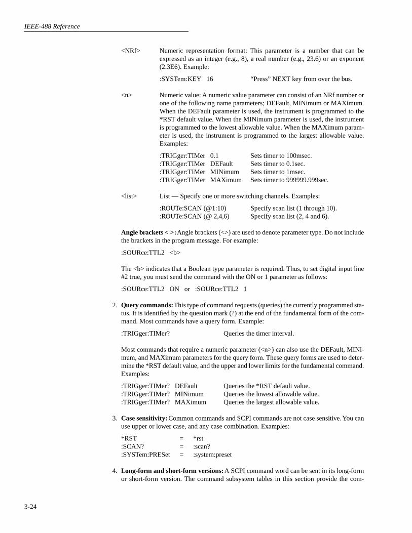
IEEE-488 Reference
3-24
<NRf> Numeric representation format: This parameter is a number that can beexpressed as an integer (e.g., 8), a real number (e.g., 23.6) or an exponent(2.3E6). Example:
:SYSTem:KEY 16 “Press” NEXT key from over the bus.
<n> Numeric value: A numeric value parameter can consist of an NRf number orone of the following name parameters; DEFault, MINimum or MAXimum.When the DEFault parameter is used, the instrument is programmed to the*RST default value. When the MINimum parameter is used, the instrumentis programmed to the lowest allowable value. When the MAXimum param-eter is used, the instrument is programmed to the largest allowable value.Examples:
:TRIGger:TIMer 0.1 Sets timer to 100msec.:TRIGger:TIMer DEFault Sets timer to 0.1sec.:TRIGger:TIMer MINimum Sets timer to 1msec.:TRIGger:TIMer MAXimum Sets timer to 999999.999sec.
<list> List — Specify one or more switching channels. Examples:
:ROUTe:SCAN (@1:10) Specify scan list (1 through 10).:ROUTe:SCAN (@ 2,4,6) Specify scan list (2, 4 and 6).
Angle brackets < >:
Angle brackets (<>) are used to denote parameter type. Do not includethe brackets in the program message. For example:
:SOURce:TTL2 <b>
The <b> indicates that a Boolean type parameter is required. Thus, to set digital input line#2 true, you must send the command with the ON or 1 parameter as follows:
:SOURce:TTL2 ON or :SOURce:TTL2 1
2.
Query commands:
This type of command requests (queries) the currently programmed sta-tus. It is identified by the question mark (?) at the end of the fundamental form of the com-mand. Most commands have a query form. Example:
:TRIGger:TIMer? Queries the timer interval.
Most commands that require a numeric parameter (<n>) can also use the DEFault, MINi-mum, and MAXimum parameters for the query form. These query forms are used to deter-mine the *RST default value, and the upper and lower limits for the fundamental command.Examples:
:TRIGger:TIMer? DEFault Queries the *RST default value.:TRIGger:TIMer? MINimum Queries the lowest allowable value.:TRIGger:TIMer? MAXimum Queries the largest allowable value.
3.
Case sensitivity:
Common commands and SCPI commands are not case sensitive. You canuse upper or lower case, and any case combination. Examples:
*RST = *rst:SCAN? = :scan?:SYSTem:PRESet = :system:preset
4.
Long-form and short-form versions:
A SCPI command word can be sent in its long-formor short-form version. The command subsystem tables in this section provide the com-

IEEE-488 Reference
3-25
mands in the long-form version. However, the short-form version is indicated by upper casecharacters. Examples:
:SYSTem:PRESet Long-form:SYST:PRES Short-form:SYSTem:PRES Long and short-form combination
Note that each command word must be in long-form or short-form, and not something inbetween. For example, :SYSTe:PRESe is illegal and will generate an error. The commandwill not be executed.
Short-form rules:
The following rules can be used to determine the short-form version ofany SCPI command:
A. If the length of the command word is four letters or less, there is no short-form version.Example:
:auto = :auto
B. The following rules apply to command words that exceed four letters:
a. If the fourth letter of the command word is a vowel, delete it and all the letters afterit. Example:
:immediate = :imm
Rule exception – The short-form version of the following command uses only thefirst two letters of the word:
:TCouple = :tc
b. If the fourth letter of the command word is a consonant, retain it but drop all theletters after it. Example:
:output = :outp
C. If there is a question mark (?; query) or a non-optional number included in the com-mand word, it must be included in the short-form version. Examples:
:delay? = :del?:layer2 = :lay2
D. As previously explained, command words or characters that are enclosed in brackets([]) are optional and need not be included in the program message.

IEEE-488 Reference
3-26
Program messages
A program message is made up of one or more command words sent by the computer to theinstrument. Each common command is simply a three letter acronym preceded by an asterisk(*). SCPI commands are categorized into subsystems and are structured as command paths. Thefollowing command paths are contained in the :STATus subsystem and are used to help explainhow command words are structured to formulate program messages.
:STATus Path (Root):OPERation Path
:PTRansition <NRf> Command and parameter:NTRansition <NRf> Command and parameter:ENABle <NRf> Command and parameter
:PRESet Command
1.
Single command messages:
There are three levels to the above command structure. Thefirst level is made up of the root command (:STATus) and serves as a path. The second levelis made up of another path (:OPERation) and a command (:PRESet). The third path is madeup of three commands for the :OPERation path. The four commands in this structure canbe executed by sending four separate program messages as follows:
:stat:oper:ptr <NRf>:stat:oper:ntr <NRf>:stat:oper:enab <NRf>:stat:pres
In each of the above program messages, the path pointer starts at the root command (:stat)and moves down the command levels until the command is executed.
2.
Multiple command messages:
Multiple commands can be sent in the same program mes-sage as long as they are separated by semicolons (;). Example showing two commands inone program message:
:stat:pres; :stat:oper:enab <NRf>
When the above message is sent, the first command word is recognized as the root com-mand (:stat). When the next colon is detected, the path pointer moves down to the next com-mand level and executes the command. When the path pointer sees the colon after thesemicolon (;), it resets back to the root level and starts over.
Commands that are on the same command level can be executed without having to retypethe entire command path. Example:
:stat:oper:enab <NRf>; ptr <NRf>; ntr <NRf>
After the first command (:enab) is executed, the path pointer is at the third command levelin the structure. Since :ptr and :ntr are also on the third level, they can be typed in withoutrepeating the entire path name. Notice that the leading colon for :ptr and :ntr are notincluded in the program message. If a colon were included, the path pointer would reset tothe root level and expect a root command. Since neither :ptr nor :ntr are root commands, anerror would occur.

IEEE-488 Reference
3-27
3. Command path rules:
A. Each new program message must begin with the root command, unless it is optional(e.g., [:SENSe]). If the root is optional, simply treat a command word on the next levelas the root.
B. The colon (:) at the beginning of a program message is optional and need not be used.Example:
:stat:pres = stat:pres
C. When the path pointer detects a colon (:) it will move down to the next command level.An exception is when the path pointer detects a semicolon (;), which is used to separatecommands within the program message (see next rule).
D. When the path pointer detects a colon (:) that immediately follows a semicolon (;), itresets back to the root level.
E. The path pointer can only move down. It cannot be moved up a level. Executing a com-mand at a higher level requires that you start over at the root command.
4.
Using common commands and SCPI commands in same message:
Both common com-mands and SCPI commands can be used in the same message as long as they are separatedby semicolons (;). A common command can be executed at any command level and will notaffect the path pointer. Example:
:stat:oper:enab <NRf>; ptr <NRf>; *ESE <NRf>; ntr <NRf>
5.
Program Message Terminator (PMT):
Each program message must be terminated withan LF (line feed), EOI (end or identify) or an LF + EOI. The bus will hang if your computerdoes not provide this termination. The following example shows how a multiple commandprogram message must be terminated:
:rout:open all; scan (@1:5) <PMT>
6. Command execution rules:
A. Commands are executed in the order that they are presented in the program message.
B. An invalid command will generate an error and, of course, not be executed.
C. Valid commands that precede an invalid command in a multiple command programmessage will be executed.
D. Valid commands that follow an invalid command in a multiple command program mes-sage will be ignored.
Response messages
A response message is the message sent by the instrument to the computer in response to a querycommand program message.
1. Sending a response message: After sending a query command, the response message isplaced in the Output Queue. When the Model 2002 is then addressed to talk, the responsemessage is sent from the Output Queue to the computer.
2. Multiple response messages: If you send more than one query command in the sameprogram message (see Multiple command messages), the multiple response message for allthe queries is sent to the computer when the Model 2002 is addressed to talk. The responsesare sent in the order that the query commands were sent and are separated by semicolons(;). Items within the same query are separated by commas (,). The following example shows

IEEE-488 Reference
3-28
the response message for a program message that contains four single item querycommands:
0; 1; 1; 0
3.
Response Message Terminator (RMT):
Each response message is terminated with an LF(line feed) and EOI (end or identify). The following example shows how a multipleresponse message is terminated:
0; 1; 1; 0 <RMT>
Message exchange protocol
The message exchange protocol can be summarized by the two following rules:
Rule 1. You must always tell the Model 2002 what to send to the computer.
The following two steps must always be performed, in this order, to send information from theinstrument to the computer:
1. Send the appropriate query command(s) in a program message.
2. Address the Model 2002 to talk.
Rule 2. The complete response message must be received by the computer before anotherprogram message can be sent to the Model 2002.
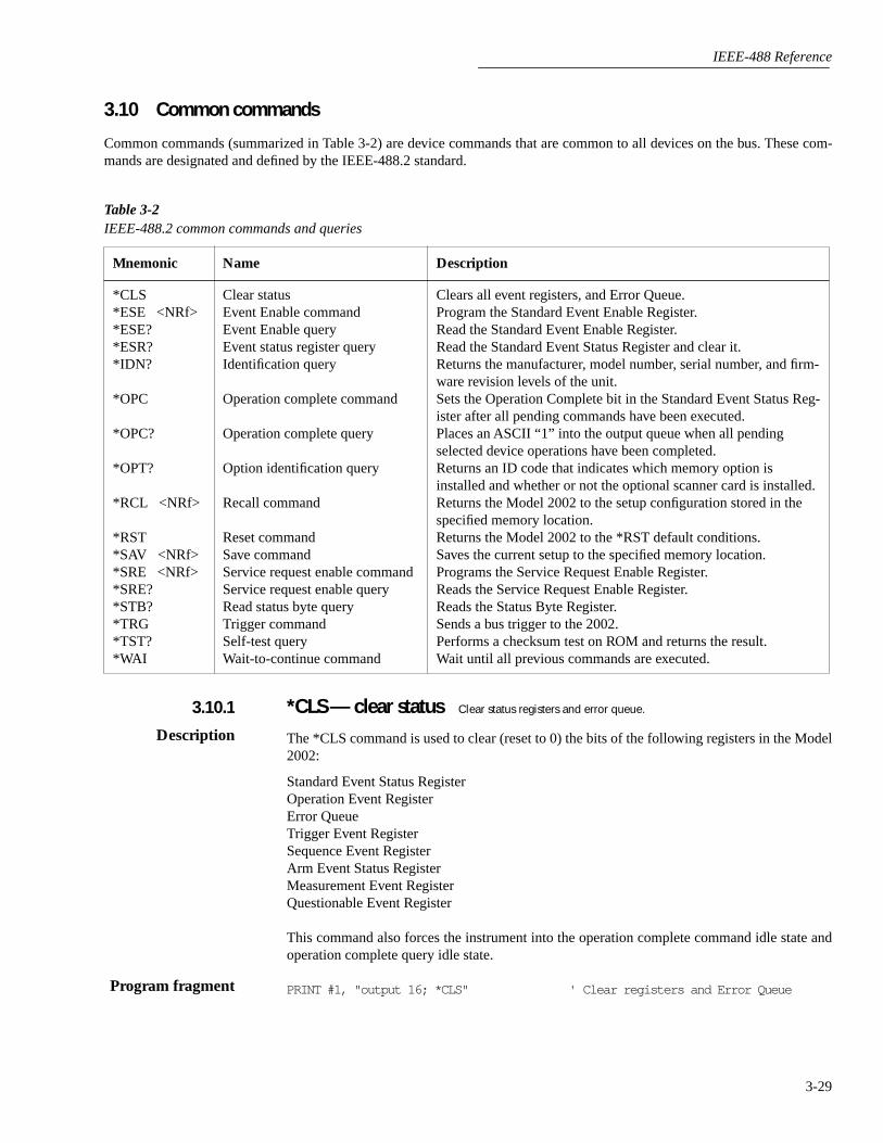
IEEE-488 Reference
3-29
3.10 Common commands
Common commands (summarized in Table 3-2) are device commands that are common to all devices on the bus. These com-mands are designated and defined by the IEEE-488.2 standard.
Table 3-2
IEEE-488.2 common commands and queries
Mnemonic Name Description
*CLS*ESE <NRf>*ESE?*ESR?*IDN?
*OPC
*OPC?
*OPT?
*RCL <NRf>
*RST*SAV <NRf>*SRE <NRf>*SRE?*STB?*TRG*TST?*WAI
Clear statusEvent Enable commandEvent Enable queryEvent status register queryIdentification query
Operation complete command
Operation complete query
Option identification query
Recall command
Reset commandSave commandService request enable commandService request enable queryRead status byte queryTrigger commandSelf-test queryWait-to-continue command
Clears all event registers, and Error Queue.Program the Standard Event Enable Register.Read the Standard Event Enable Register.Read the Standard Event Status Register and clear it.Returns the manufacturer, model number, serial number, and firm-ware revision levels of the unit.Sets the Operation Complete bit in the Standard Event Status Reg-ister after all pending commands have been executed.Places an ASCII “1” into the output queue when all pending selected device operations have been completed.Returns an ID code that indicates which memory option is installed and whether or not the optional scanner card is installed.Returns the Model 2002 to the setup configuration stored in the specified memory location.Returns the Model 2002 to the *RST default conditions.Saves the current setup to the specified memory location.Programs the Service Request Enable Register.Reads the Service Request Enable Register.Reads the Status Byte Register.Sends a bus trigger to the 2002.Performs a checksum test on ROM and returns the result.Wait until all previous commands are executed.
*CLS — clear status
Clear status registers and error queue.
The *CLS command is used to clear (reset to 0) the bits of the following registers in the Model2002:
Standard Event Status RegisterOperation Event RegisterError QueueTrigger Event RegisterSequence Event RegisterArm Event Status RegisterMeasurement Event RegisterQuestionable Event Register
This command also forces the instrument into the operation complete command idle state andoperation complete query idle state.
PRINT #1, "output 16; *CLS" ' Clear registers and Error Queue
3.10.1
Description
Program fragment
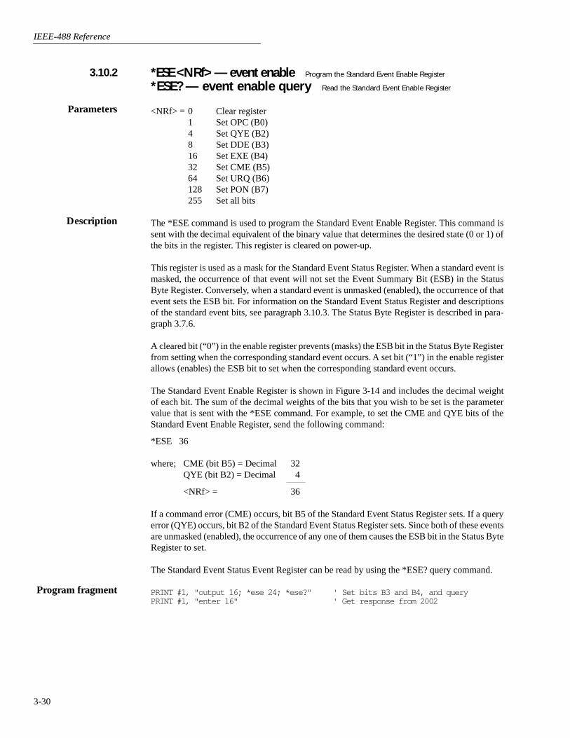
IEEE-488 Reference
3-30
*ESE <NRf> — event enable
Program the Standard Event Enable Register
*ESE? — event enable query
Read the Standard Event Enable Register
<NRf> = 0 Clear register1 Set OPC (B0)4 Set QYE (B2)8 Set DDE (B3)16 Set EXE (B4)32 Set CME (B5)64 Set URQ (B6)128 Set PON (B7)255 Set all bits
The *ESE command is used to program the Standard Event Enable Register. This command issent with the decimal equivalent of the binary value that determines the desired state (0 or 1) ofthe bits in the register. This register is cleared on power-up.
This register is used as a mask for the Standard Event Status Register. When a standard event ismasked, the occurrence of that event will not set the Event Summary Bit (ESB) in the StatusByte Register. Conversely, when a standard event is unmasked (enabled), the occurrence of thatevent sets the ESB bit. For information on the Standard Event Status Register and descriptionsof the standard event bits, see paragraph 3.10.3. The Status Byte Register is described in para-graph 3.7.6.
A cleared bit (“0”) in the enable register prevents (masks) the ESB bit in the Status Byte Registerfrom setting when the corresponding standard event occurs. A set bit (“1”) in the enable registerallows (enables) the ESB bit to set when the corresponding standard event occurs.
The Standard Event Enable Register is shown in Figure 3-14 and includes the decimal weightof each bit. The sum of the decimal weights of the bits that you wish to be set is the parametervalue that is sent with the *ESE command. For example, to set the CME and QYE bits of theStandard Event Enable Register, send the following command:
*ESE 36
where; CME (bit B5) = Decimal 32QYE (bit B2) = Decimal 4
<NRf> = 36
If a command error (CME) occurs, bit B5 of the Standard Event Status Register sets. If a queryerror (QYE) occurs, bit B2 of the Standard Event Status Register sets. Since both of these eventsare unmasked (enabled), the occurrence of any one of them causes the ESB bit in the Status ByteRegister to set.
The Standard Event Status Event Register can be read by using the *ESE? query command.
PRINT #1, "output 16; *ese 24; *ese?" ' Set bits B3 and B4, and queryPRINT #1, "enter 16" ' Get response from 2002
3.10.2
Parameters
Description
Program fragment

IEEE-488 Reference
3-31
*ESR? — event status register query
Read the Standard Event Status Register and clear it.
This command is used to acquire the value (in decimal) of the Standard Event Status Register(see Figure 3-15). The binary equivalent of the returned decimal value determines which bits inthe register are set. This register is cleared on power-up or when *CLS is sent.
A set bit in this register indicates that a particular event has occurred. For example, for anacquired decimal value of 48, the binary equivalent is 00110000. For this binary value, bits B4and B5 of the Standard Event Status Register are set. These set bits indicate that a device-dependent error and command error have occurred.
The bits of the Standard Event Status Register are described as follows:
Bit B0, Operation Complete (OPC) —
Set bit indicates that all pending selected device oper-ations are completed and the Model 2002 is ready to accept new commands. This bit only setsin response to the *OPC? query command (see paragraph 3.10.6).
Bit B1 —
Not Used.
Bit B2, Query Error (QYE) —
Set bit indicates that you attempted to read data from an emptyOutput Queue.
Bit B3, Device-dependent Error (DDE) —
Set bit indicates that an instrument operation didnot execute properly due to some internal condition.
Bit B4, Execution Error (EXE) —
Set bit indicates that the Model 2002 detected an error whiletrying to execute a command.
Bit B5, Command Error (CME) —
Set bit indicates that a command error has occurred. Com-mand errors include:
Figure 3-14Standard Event Enable Register
B7 B6 B5 B4 B3 B2 B1 B0
0/1 0/1 0/1
Bit Position
Event
Decimal Weighting
Value
Value : 1 = Enable Standard Event 0 = Disable (Mask) Standard Event
PON URQ CME DDEEXE QYE OPC
0/1 0/1 0/1 0/1
(2 )7 (2 )6 (2 )5 (2 )4 (2 )3 (2 )2 (2 )0
64 32 1128 16 8 4
Note : Bits B8 through B15 are not shown since they are not used.
Events : PON = Power On URQ = User Request CME = Command Error EXE = Execution Error DDE = Device-dependent Error QYE = Query Error OPC = Operation Complete
3.10.3
Description

IEEE-488 Reference
3-32
1. IEEE-488.2 syntax error: Model 2002 received a message that does not follow the definedsyntax of the IEEE-488.2 standard.
2. Semantic error: Model 2002 received a command that was misspelled, or received anoptional IEEE-488.2 command that is not implemented.
3. The instrument received a Group Execute Trigger (GET) inside a program message.
Bit B6, User Request (URQ) —
Set bit indicates that the LOCAL key on the Model 2002 frontpanel was pressed.
Bit B7, Power On (PON) —
Set bit indicates that the Model 2002 has been turned off andturned back on since the last time this register has been read.
PRINT #1, "output 16; *esr?" ' Query registerPRINT #1, "enter 16" ' Get response message from 2002
*IDN? — identification query
Read the identification code
The identification code includes the manufacturer, model number, serial number, and firmwarerevision levels, and is sent in the following format:
KEITHLEY INSTRUMENTS INC., MODEL 2002, xxxxxxx, yyyyy/zzzzz
where; xxxxxxx is the serial numberyyyyy/zzzzz is the firmware revision levels of thedigital board ROM and display board ROM.
PRINT #1, "output 16; *idn?" ' Query ID codePRINT #1, "enter 16" ' Get response message from 2002
Program fragment
Figure 3-15Standard Event Status Register
B7 B6 B5 B4 B3 B2 B1 B0
0/1 0/1 0/1
Bit Position
Event
Decimal Weighting
Value
Value : 1 = Event Bit Set 0 = Event Bit Cleared
Events : PON = Power On URQ = User Request CME = Command Error EXE = Execution Error DDE = Device-dependent Error QYE = Query Error OPC = Operation Complete
PON URQ CME EXE DDE QYE OPC
0/1 0/1 0/1 0/1
(2 )7 (2 )6 (2 )5 (2 )4 (2 )3 (2 )2 (2 )0
64 32 1128 16 8 4
Note : Bits B8 through B15 are not shown since they are not used.
3.10.4
Description
Program fragment

IEEE-488 Reference
3-33
*OPC — operation complete
Set the Operation Complete bit in the Standard Event StatusRegister after all pending commands are complete.
On power-up, or when *CLS or *RST is executed, the Model 2002 goes into the OperationComplete Command Idle State (OCIS). In this state there are no pending overlapped com-mands. There are three overlapped commands used by the Model 2002:
:INITiate:INITiate:CONTinuous ON*TRG
When the *OPC command is sent, the Model 2002 exits from OCIS and enters the OperationComplete Command Active State (OCAS). In OCAS, the instrument continuously monitors theNo-Operation-Pending flag. After the last pending overlapped command is complete (No-Operation-Pending flag set to true), the Operation Complete (OPC) bit in the Standard EventStatus Register sets, and the instrument goes back into OCIS.
Note that the instrument always goes into OCAS when *OPC is executed. If there are no pend-ing command operations (e.g. trigger model in idle state), the Model 2002 immediately sets theOPC bit and returns to OCIS.
When used with the :INITiate or :INITiate:CONTinuous ON command, the OPC bit of the Stan-dard Event Status Register will not set until the Model 2002 goes back into the idle state. Theinitiate operations are not considered finished until the instrument goes into the idle state.
When used with the *TRG command, the OPC bit will not set until the operations associatedwith the *TRG command (and the initiate command) are finished. The *TRG command is con-sidered to be finished when the Device Action completes or when operation stops at a controlsource to wait for an event (see Trigger Model in paragraph 3.8).
In order to use *OPC exclusively with the *TRG command, you will have to first force the com-pletion of the initiate command so that only the *TRG command is pending. To do this, sendthe :ABORt command to place the instrument in idle, which (by definition) completes the ini-tiate command. Since continuous initiation is on, operation continues on into the Trigger Model.After sending the *TRG command, the OPC bit sets when the *TRG command is finished.
GOSUB ReadRegister ' Clear register by reading itPRINT #1, "output 16; :init:cont off; :abort" ' Place 2002 in idlePRINT #1, "output 16; :init; *opc" ' Start measurements and send *OPCSLEEP 2 ' Wait two secondsGOSUB ReadRegister ' Read register to show that OPC is not setPRINT #1, "output 16; :abort" ' Place 2002 back in idleGOSUB ReadRegister ' Read register to show that OPC is now setEND
ReadRegister:PRINT #1, "output 16; *esr?" ' Query Standard Event Status RegisterPRINT #1, "enter 16" ' Get response message from 2002LINE INPUT #2, a$ ' Read decimal value of registerPRINT a$ ' Display decimal value of registerRETURN
3.10.5
Description
Program fragment

IEEE-488 Reference
3-34
*OPC? — operation complete query
Place a “1” in the Output Queue after all pendingoperations are completed
On power-up, or when *CLS or *RST is executed, the Model 2002 goes into the OperationComplete Command Query Idle State (OQIS). In this state there are no pending overlappedcommands. There are three overlapped commands used by the Model 2002:
:INITiate:INITiate:CONTinuous ON*TRG
When the *OPC? command is sent, the Model 2002 exits from OQIS and enters the OperationComplete Command Active State (OQAS). In OQAS, the instrument continuously monitors theNo-Operation-Pending flag. After the last pending overlapped command is completed (No-Operation-Pending flag set to true), an ASCII character “1” is placed into the Output Queue, theMessage Available (MAV) bit in the Status Byte sets, and the instrument goes back into OQIS.Addressing the Model 2002 to talk sends the ASCII “1” to the computer.
Note that the instrument always goes into OQAS when *OPC? is executed. If there are no pend-ing command operations (e.g. trigger model in idle state), the Model 2002 immediately placesan ASCII “1” in the Output Queue, sets the MAV bit and returns to OQIS.
When used with the :INITiate or :INITiate:CONTinuous ON command, an ASCII “1” will notbe sent to the Output Queue and the MAV bit will not set until the Model 2002 goes back intothe idle state. The initiate operations are not considered finished until the instrument goes intothe idle state.
When used with the *TRG command, an ASCII “1” will not be placed into the Output Queueand the MAV bit will not set until the operations associated with the *TRG command (and theinitiate command) are finished. The *TRG command is considered to be finished when theDevice Action completes or when operation stops at a control source to wait for an event (seeTrigger Model in paragraph 3.8).
In order to use *OPC? exclusively with the *TRG command you will have to first force the com-pletion of the initiate command so that only the *TRG command is pending. To do this, send the:ABORt command to place the instrument in idle, which (by definition) completes the initiatecommand. Since continuous initiation is on, operation continues on into the Trigger Model.After sending the *TRG command, an ASCII “1” is placed in the Output Queue and the MAVbit sets when the *TRG command is finished.
After *OPC? is executed, additional commands cannot be sent to the Model 2002 until the pend-ing overlapped commands have finished. For example, :INITiate:CONTinuous ON followed by*OPC? locks up the instrument and requires a device clear (DCL or SDC) before it will acceptany more commands.
NOTE
See *OPC, *TRG and *WAI for more information.
PRINT #1, "output 16; :syst:pres" ' Select defaultsPRINT #1, "output 16; :init:cont off; :abort" ' Place 2002 in idlePRINT #1, "output 16; :arm:coun 1" ' Program for 5 measurements and
stop (idle)PRINT #1, "output 16; :arm:lay2: coun 1"PRINT #1, "output 16; :trig: coun 5; sour tim"PRINT #1, "outut 16; :init; *opc?" ' Start measurements and send *opc?PRINT #1, "enter 16" ' Get response when 2002 goes into idleLINE INPUT #2, a$ ' Read contents of Output QueuePRINT a$ ' Display the ASCII "1"
3.10.6
Description
Program fragment

IEEE-488 Reference
3-35
*OPT? — option identification query
Determine which options are installed in theModel 2002.
The response message is made up of two comma separated fields. The first field indicates thepresence or absence of extra memory.
0 No extra memory (8k bytes volatile)MEM1 Memory Option 1 (32k bytes non-volatile)MEM2 Memory Option 2 (128k bytes non-volatile)
The second field indicates the presence or absence of the Model 2001-SCAN scanner card.
0 No scanner card installed2001-SCAN Model 2001-SCAN installed
Example: The following response message indicates that Memory Option 2 and the scannercard are installed:
MEM2, 2001-SCAN
PRINT #1, "output 16; *opt?" ' Query installed optionsPRINT #1, "enter 16" ' Send response message to 2002
*RCL —recall
Return to a setup stored in memory.
No extended Model 2002-MEM1 Model 2002-MEM2memory installed installed
<NRf> = 0 <NRf> = 0 to 4 <NRf> = 0 to 9
This command is used to return the Model 2002 to a setup configuration stored at a memorylocation. The *SAV command is used to store a setup configuration at a memory location (seeparagraph 3.10.10).
If the Model 2002 does not have any extended memory installed, only one setup configurationcan be saved and recalled. In this situation, memory location “0” is the only valid parameter forthe *RCL command. If the Model 2002-MEM1 memory element is installed, up to five setupconfigurations can be saved and recalled. In this situation, memory locations “0” through “4”are valid parameters. If the Model 2002-MEM2 memory element is installed, up to 10 setupconfigurations can be saved and recalled. Memory locations “0” through “9” are then validparameters.
The Model 2002 is shipped from the factory with :SYSTem:PRESet defaults loaded into theavailable setup memories. If a recall error occurs, the setup memories default to the:SYSTem:PRESet values.
PRINT #1, "output 16; *rcl 0" ' Recall setup stored at memory location 0
3.10.7
Description
Program fragment
3.10.8
Parameters
Description
Program fragment

IEEE-488 Reference
3-36
*RST — reset
Reset the Model 2002
When the *RST command is sent, the Model 2002 performs the following operations:
1. Returns the Model 2002 to the *RST default conditions (see SCPI tables).
2. Cancels all pending commands.
3. Cancels response to any previously received *OPC and *OPC? commands.
PRINT #1, "output 16; *rst" ' Return 2002 to *rst defaults
*SAV — save
Save the current setup in memory
No extended Model 2002-MEM1 Model 2002-MEM2memory installed installed
<NRf> = 0 <NRf> = 0 to 4 <NRf> = 0 to 9
The *SAV command is used to save the current instrument setup configuration in memory forlater recall. Any control affected by *RST can be saved by the *SAV command. The *RCL com-mand is used to restore the instrument to a saved setup configuration.
If the Model 2002 does not have any extended memory installed, only one setup configurationcan be saved and recalled. In this situation, memory location “0” is the only valid parameter forthe *SAV command. If the Model 2002-MEM1 memory element is installed, up to five setupconfigurations can be saved and recalled. In this situation, memory locations “0” through “4”are valid parameters. If the Model 2002-MEM2 memory element is installed, up to 10 setupconfigurations can be saved and recalled. Memory locations “0” through “9” are then validparameters.
PRINT #1, "output 16; *SAV 0" ' Store setup at memory location 0.
*SRE <NRf> — service request enable
Program the Service Request Enable Register
*SRE? — service request enable query
Read the Service Request Enable Register
<NRf> = 0 Clears enable register= 1 Set MSB bit (Bit 0)= 4 Set EAV bit (Bit 2)= 8 Set QSB bit (Bit 3)= 16 Set MAV bit (Bit 4)= 32 Set ESB bit (Bit 5)= 128 Set OSB bit (Bit 7)= 255 Sets all bits
The *SRE command is used to program the Service Request Enable Register. This command issent with the decimal equivalent of the binary value that determines the desired state (0 or 1) ofeach bit in the register. This register is cleared on power-up.
This enable register is used along with the Status Byte Register to generate service requests(SRQ). With a bit in the Service Request Enable Register set, an SRQ occurs when the corre-sponding bit in the Status Byte Register is set by an appropriate event. For details on registerstructure, refer to paragraph 3.7.
3.10.9
Description
Program fragment
3.10.10
Parameters
Description
Program fragment
3.10.11
Parameters
Description

IEEE-488 Reference
3-37
The Service Request Enable Register is shown in Figure 3-16. Notice that the decimal weightof each bit is included in the illustration. The sum of the decimal weights of the bits that youwish to set is the value that is sent with the *SRE command. For example, to set the ESB andMAV bits of the Service Request Enable Register, send the following command:
*SSE 34
where; ESB (bit B5) = Decimal 32MAV (bit B4) = Decimal 16
<NRf> = 48
The contents of the Service Request Enable Register can be read using the *SRE? query com-mand.
PRINT #1, "output 16; *sre 32; *sre?" ' Unmask ESB bit and query registerPRINT #1, "enter 16" ' Send response message to 2002
Program fragment
Figure 3-16Service Request Enable Register
B7 B6 B5 B4 B3 B2 B1 B0
(2 )7 (2 )5 (2 )4 (2 )3 (2 )2 (2 )0
32
0/1
Bit Position
Event
Decimal Weighting
Value
Value : 1 = Enable Service Request Event 0 = Disable (Mask) Service
Request Event
Events : OSB = Operation Summary Bit ESB = Event Summary Bit MAV = Message Available QSB = Questionable Summary Bit EAV = Error Available MSB = Measurement Summary Bit
OSB ESB MAV QSB EAV
0/1 0/1 0/1 0/1
128 16 8 4
MSB
1
0/1
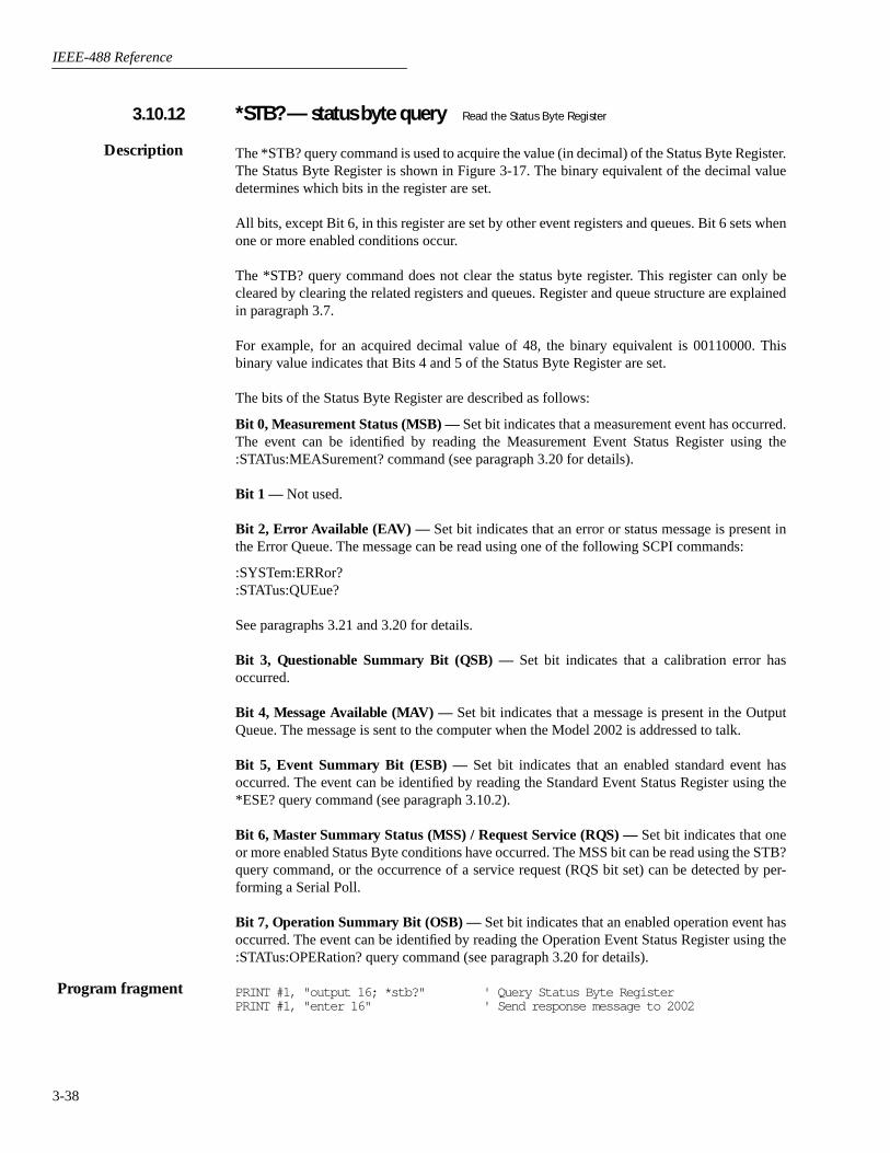
IEEE-488 Reference
3-38
*STB? — status byte query
Read the Status Byte Register
The *STB? query command is used to acquire the value (in decimal) of the Status Byte Register.The Status Byte Register is shown in Figure 3-17. The binary equivalent of the decimal valuedetermines which bits in the register are set.
All bits, except Bit 6, in this register are set by other event registers and queues. Bit 6 sets whenone or more enabled conditions occur.
The *STB? query command does not clear the status byte register. This register can only becleared by clearing the related registers and queues. Register and queue structure are explainedin paragraph 3.7.
For example, for an acquired decimal value of 48, the binary equivalent is 00110000. Thisbinary value indicates that Bits 4 and 5 of the Status Byte Register are set.
The bits of the Status Byte Register are described as follows:
Bit 0, Measurement Status (MSB) —
Set bit indicates that a measurement event has occurred.The event can be identified by reading the Measurement Event Status Register using the:STATus:MEASurement? command (see paragraph 3.20 for details).
Bit 1 —
Not used.
Bit 2, Error Available (EAV) —
Set bit indicates that an error or status message is present inthe Error Queue. The message can be read using one of the following SCPI commands:
:SYSTem:ERRor?:STATus:QUEue?
See paragraphs 3.21 and 3.20 for details.
Bit 3, Questionable Summary Bit (QSB) —
Set bit indicates that a calibration error hasoccurred.
Bit 4, Message Available (MAV) —
Set bit indicates that a message is present in the OutputQueue. The message is sent to the computer when the Model 2002 is addressed to talk.
Bit 5, Event Summary Bit (ESB) —
Set bit indicates that an enabled standard event hasoccurred. The event can be identified by reading the Standard Event Status Register using the*ESE? query command (see paragraph 3.10.2).
Bit 6, Master Summary Status (MSS) / Request Service (RQS) —
Set bit indicates that oneor more enabled Status Byte conditions have occurred. The MSS bit can be read using the STB?query command, or the occurrence of a service request (RQS bit set) can be detected by per-forming a Serial Poll.
Bit 7, Operation Summary Bit (OSB) —
Set bit indicates that an enabled operation event hasoccurred. The event can be identified by reading the Operation Event Status Register using the:STATus:OPERation? query command (see paragraph 3.20 for details).
PRINT #1, "output 16; *stb?" ' Query Status Byte RegisterPRINT #1, "enter 16" ' Send response message to 2002
3.10.12
Description
Program fragment

IEEE-488 Reference
3-39
*TRG — trigger
Send a GPIB trigger to the Model 2002.
The *TRG command is used to issue a GPIB trigger to the Model 2002. It has the same effectas a group execute trigger (GET).
The *TRG command is used as an arm, scan and/or measure event to control operation. TheModel 2002 reacts to this trigger if GPIB is the programmed control source. The control sourceis programmed from the :TRIGger subsystem (see paragraph 3.22).
*TRG can also be used as the pre-trigger for buffer operation.
PRINT #1, "output 16; *trg" ' Trigger 2002
*TST? — self-test query
Run the self-test and acquire the result.
This query command is used to perform a checksum test on ROM and places the coded result(0 or 1) in the Output Queue. When the Model 2002 is addressed to talk, the coded result is sentfrom the Output Queue to the computer.
A returned value of zero (0) indicates that the test passed, and a value of one (1) indicates thatthe test has failed.
PRINT #1, "output 16; *tst?" ' Run test and query resultPRINT #1, "enter 16" ' Send response message to 2002
Figure 3-17Status Byte Register
B7 B6 B5 B4 B3 B2 B1 B0
(2 ) (2 )6 (2 )5 (2 )4 (2 )3 (2 )2 (2 )0
32
0/1
Bit Position
Event
Decimal Weighting
Value
Value : 1 = Event Bit Set 0 = Event Bit Cleared
Events : OSB = Operation Summary Bit MSS = Master Summary Status RQS = Request Service ESB = Event Summary Bit MAV = Message Available QSB = Questionable Summary Bit EAV = Error Available MSB = Measurement Summary Bit
OSB ESB MAV QSB EAV
0/1 0/1 0/1 0/1
128 16 8 4
MSS,RQS
64
0/1
MSB
1
0/1
7
3.10.13
Description
Program fragment
3.10.14
Description
Program fragment

IEEE-488 Reference
3-40
*WAI — wait-to-continue
Prevent the execution of commands until all previous commands
are completed.
There are two types of device commands; Sequential commands and Overlapped commands. ASequential command is a command whose operations are allowed to finish before the next com-mand is executed. An Overlapped command is a command that allows the execution of subse-quent commands while device operations of the Overlapped command are still in progress. The*WAI command is used to hold off the execution of subsequent commands until the device oper-ations of all previous Overlapped commands are finished. The *WAI command is not neededfor Sequential commands.
There are three Overlapped commands in the Model 2002; :INITiate, :INITiate:CONTinuousON and *TRG.
NOTE
See *OPC, *OPC? and *TRG for more information.
The :INITiate commands take the Model 2002 out of the idle state. The device operations of:INITiate are not considered complete until the Model 2002 goes back into idle. By sending the*WAI command after the :INITiate command, all subsequent commands will not execute untilthe Model 2002 goes back into idle.
The *TRG command issues a bus trigger which could be used to provide the arm, scan and mea-sure events for the Trigger Model. By sending the *WAI command after the *TRG command,subsequent commands will not be executed until the pointer for the Trigger Model has finishedmoving in response to *TRG and has settled at its next state.
PRINT #1, "output 16; :syst:pres" ' Select defaultsPRINT #1, "output 16; :init:cont off; :abort" ' Place 2002 in idlePRINT #1, "output 16; :arm:coun 1" ' Program for 30 measurements and
then stop (idle)PRINT #1, "output 16; :arm:lay2:coun 1"PRINT #1, "output 16; :trig:coun 30; sour tim"PRINT #1, "output 16; :init; *wai" ' Start measurements and send
*waiPRINT #1, "output 16; :data?" ' Query a readingPRINT #1, "enter 16" ' Get reading after 2002 goes
into idleLINE INPUT #2, a$ ' Read the readingPRINT a$ ' Display the reading
3.10.15
Description
Program fragment

IEEE-488 Reference
3-41
3.11 Signal oriented measurement commands
The signal oriented command group is used to acquire readings using a set of high-level instructions to control the measurementprocess. These commands are summarized in Table 3-3.
Table 3-3Signal oriented measurement command summary
Command Description
:FETCh?:CONFigure:<function>:READ?:MEASure[:<function>]?
Requests the latest reading.Places the 2002 in a “one-shot” measurement mode for the specified function.Performs an :ABORt, :INITiate, and a :FETCh?.Performs an :ABORt, :CONFigure:<function>, and a :READ?.
:FETCh?
This query command is used to request the latest post-processed reading. After sending thiscommand and addressing the Model 2002 to talk, the reading will be sent to the computer. Thiscommand does not affect the instrument setup.
This command does not trigger a measurement. It simply requests the last available reading.Note that this command can repeatedly return the same reading. In the absence of a new reading,this command will simply return the old reading. If your application requires “fresh” readings,use the :DATA:FRESh? command (see SENSe Subsystem).
This command is automatically asserted when the :READ? or :MEASure? command is sent.
PRINT #1, "output 16; :syst:pres" ' Select system preset defaultsPRINT #1, "output 16; :fetch?" ' Request the latest readingPRINT #1, "enter 16" ' Get response message from 2002
:CONFigure:<function>
where: <function> = VOLTage:DC DCV function= CURRent:DC DCI function= VOLTage:AC ACV function= CURRent:AC ACI function= RESistance Ω2 function= FRESistance Ω4 function= FREQuency FREQ function= TEMPerature TEMP function
:CONFigure? Query the selected function
Short-form format: :conf?
Response message: CURR:DC, VOLT:AC, CURR:AC, VOLT:DC, RES, FRES, FREQ orTEMP
Description
Program fragment
Query

IEEE-488 Reference
3-42
This command is used to configure the instrument for subsequent measurements on the specifiedfunction. Basically, this command places the instrument in a “one-shot” measurement mode.The :READ? command can then be used to trigger a measurement and acquire a reading (see:READ?).
When this command is sent, the Model 2002 will be configured as follows:
• The function specified by this command is selected.
• All controls related to the selected function are defaulted to the *RST values.
• Continuous initiation is disabled (:INITiate:CONTinuous OFF).
• The control sources in all three layers of the Trigger Model are set to Immediate.
• The count values in all three layers of the Trigger Model are set to one (1).
• The delay in all three layers of the Trigger Model are set to zero (0).
• The Model 2002 is placed in the idle state.
• All math calculations are disabled.
• Buffer operation is disabled. A storage operation currently in process will be aborted.
• Autozero controls are set to the *RST default values.
• The acquisition method is set to normal.
• All operations associated with switching cards (scanning) are disabled.
This command is automatically asserted when the :MEASure? command is sent.
PRINT #1, "output 16; :conf:volt:dc" ' Perform :CONFigure operations.
:READ?
This command is typically used to acquire a post-processed reading after the instrument hasbeen configured by the :CONFigure command. The :CONFigure command places the instru-ment in a “one-shot” measurement mode. Every time the :READ? command is then sent, a mea-surement conversion will occur and the reading will be acquired.
When this command is sent, the following commands will be executed in the order that they arepresented:
:ABORt
:INITiate
:FETCh?
When :ABORt is executed, the instrument will go into the idle state if continuous initiation isdisabled. Otherwise, operation will re-start at the beginning of the Trigger Model.
If the instrument is in the idle state, :INITiate will take the instrument out of the idle state. Ifcontinuous initiation is enabled, (:INITiate:CONTinuous ON), then the :INITiate command willgenerate an error and ignore the command.
The :FETCh? for details. Note that an “Init ignored” error will not cancel the execution of the:FETCh? command.
PRINT #1, "output 16; :conf:volt:dc" ' Select “one-shot” DCV functionPRINT #1, "output 16; :read?" ' Perform :READ? operationsPRINT #1, "enter 16" ' Get response message from 2002
Description
Program fragment
Description
Program fragment

IEEE-488 Reference
3-43
:MEASure[:<function>]?
where: <function> = VOLTage:DC DCV function= CURRent:DC DCI function= VOLTage:AC ACV function= CURRent:AC ACI function= RESistance Ω2 function= FRESistance Ω4 function= FREQuency FREQ function= TEMPerature TEMP function
This command combines all of the other signal oriented measurement commands to perform a“one-shot” measurement and acquire the reading.
When this command is sent, the following commands are executed in the order that they arepresented.
:ABORt:CONFigure:<function>:READ?
When :ABORt is executed, the instrument will go into the idle state if continuous initiation isdisabled. Otherwise, operation will re-start at the beginning of the Trigger Model.
When :CONFigure is executed, the instrument will go into a “one-shot” measurement mode.See :CONFigure for details.
When :READ? is executed, its operations will then be performed. In general, another :ABORtwill be performed, than an :INITiate and finally a FETCh? to acquire the reading. See :READ?for details.
PRINT #1, "output 16; :meas?" ' Perform :MEASure? operationsPRINT #1, "enter 16" ' Get response message from 2002
Description
Program fragment

IEEE-488 Reference
3-44
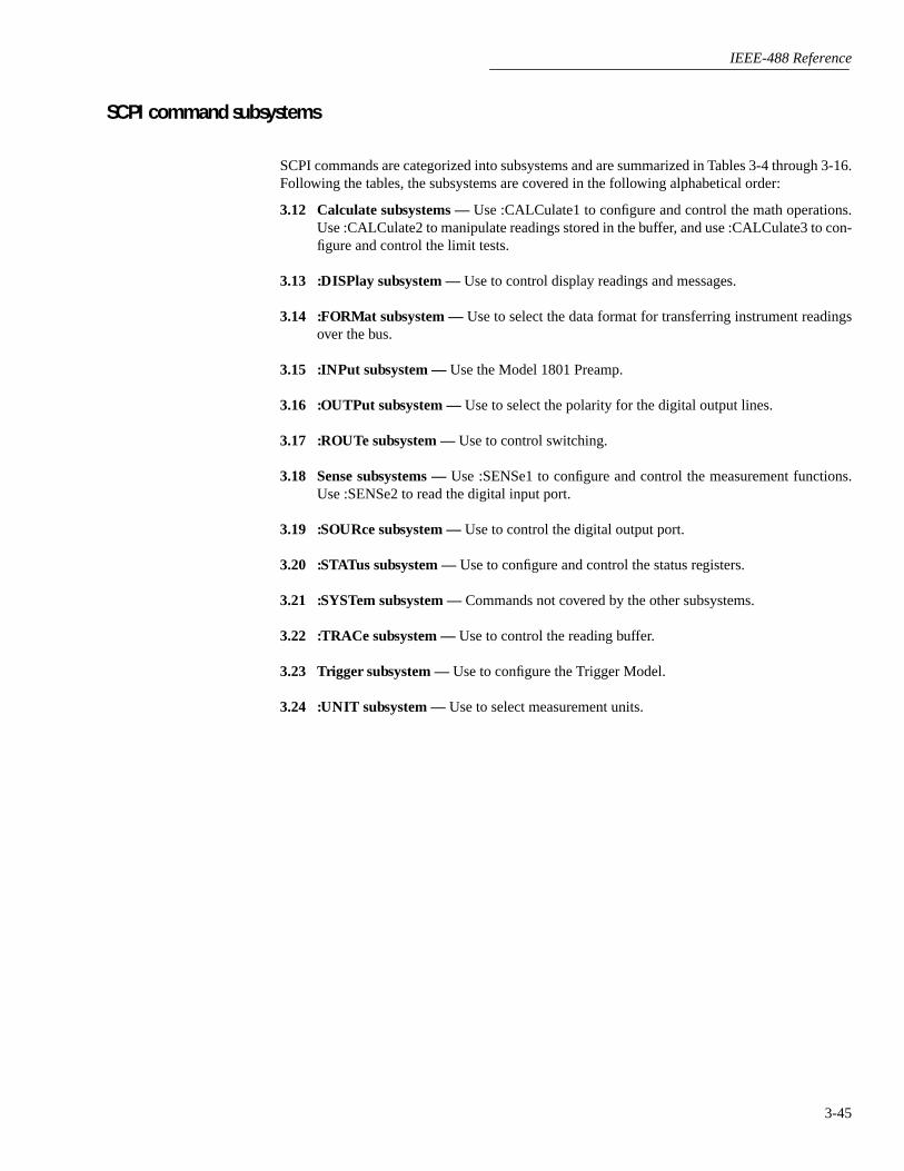
IEEE-488 Reference
3-45
SCPI command subsystems
SCPI commands are categorized into subsystems and are summarized in Tables 3-4 through 3-16.Following the tables, the subsystems are covered in the following alphabetical order:
3.12 Calculate subsystems —
Use :CALCulate1 to configure and control the math operations.Use :CALCulate2 to manipulate readings stored in the buffer, and use :CALCulate3 to con-figure and control the limit tests.
3.13 :DISPlay subsystem —
Use to control display readings and messages.
3.14 :FORMat subsystem —
Use to select the data format for transferring instrument readingsover the bus.
3.15 :INPut subsystem —
Use the Model 1801 Preamp.
3.16 :OUTPut subsystem —
Use to select the polarity for the digital output lines.
3.17 :ROUTe subsystem —
Use to control switching.
3.18 Sense subsystems —
Use :SENSe1 to configure and control the measurement functions.Use :SENSe2 to read the digital input port.
3.19 :SOURce subsystem —
Use to control the digital output port.
3.20 :STATus subsystem —
Use to configure and control the status registers.
3.21 :SYSTem subsystem —
Commands not covered by the other subsystems.
3.22 :TRACe subsystem —
Use to control the reading buffer.
3.23 Trigger subsystem —
Use to configure the Trigger Model.
3.24 :UNIT subsystem —
Use to select measurement units.

IEEE-488 Reference
3-46
SCPI Command Summary
Tables 3-4 through 3-16 summarize the commands for each SCPI subsystem.
General notes:
• Brackets ([ ]) are used to denote optional character sets. These optional characters do not have to be included in the pro-gram message. Do not use brackets in the program message.
• Angle brackets (< >) are used to indicate parameter type. Do not use angle brackets in the program message.
• The Boolean parameter (<b>) is used to enable or disable an instrument operation. 1 or ON enables the operation and 0 orOFF disables the operation.
• Upper case characters indicate the short-form version for each command word.
• Default Parameter — Listed parameters are both the *RST and :SYSTem:PRESet defaults, unless noted otherwise. Param-eter notes are located at the end of each table.
• SCPI — A checkmark (
√
) indicates that the command and its parameters are SCPI confirmed. An unmarked commandindicates that it is non-SCPI. SCPI confirmed commands that use one or more non-SCPI parameters are explained by notes.
Table 3-4
CALCulate command summary
Command DescriptionDefault parameter SCPI Ref.
:CALCulate[1]:FORMat <name>
:FORMat?:KMATh
:MA0Factor <NRf>:MA0Factor:MA1Factor <NRf>:MA1Factor:MA2Factor <NRf>:MA2Factor:PERCent <NRf>:PERCent?
:STATe <b>:STATe?:DATA
[:LATest]?:FRESh?
:IMMediate
Subsystem to control CALC 1:Select math format (NONE, POLynomial, PERCent,
PDEViation).Query math format.Path to configure math calculations:
Set “a0” for POLynomial (-9.999999e20 to +9.999999e20).Query “a0” factor.Set “a1” for POLynomial (-9.999999e20 to +9.999999e20).Query “a1” factor.Set “a2” for POLynomial (-9.999e20 to +9.999e20).Query “a2” factor.Set PERCENT (-9.999999e35 to +9.999999e35).Query PERCENT.
Enable or disable calculation.Query state of math function.Path to read math result of CALC1.
Return the last math of CALC1.Return a new (fresh) math result of CALC1.
Recalculate input data.
PERCent
0
1
0
1
0
√
√
√
√
√
√
√
√
√
√
3.12.1
:CALCulate2:FORMat <name>
:FORMat?:STATe <b>:STATe?:IMMediate:DATA?
Subsystem to control CALC 2:Select math format: (MEAN, SDEViation, MAXimum,
MINimum, PKPK, or NONE).Query math format.Enable or disable calculation.Query state of math function.Recalculate raw input data in buffer.Read math result of CALC 2.
NONE
0
√
√
√
√
√
√
√
3.12.2

IEEE-488 Reference
3-47
:CALCulate3:LIMit[1]
:UPPer[:DATA] <n>[:DATA]?:SOURce <NRf>:SOURce?
:LOWer[:DATA] <n>[:DATA]?:SOURce <NRf>:SOURce?
:STATe <b>:STATe?:FAIL?:CLEAR
[:IMMediate]:AUTO <b>:AUTO?
:LIMit2:UPPer
[:DATA] <n>[:DATA]?:SOURce <NRf>:SOURce?
:LOWer[:DATA] <n>[:DATA]?:SOURce <NRf>:SOURce?
:STATe <b>:STATe?:FAIL?:CLEAR
[:IMMediate]:AUTO <b>:AUTO?
:PASS:SOURce <NRf>
:CLIMits:FAIL?
:BSTRobe:STATe <b>:STATe?
:IMMediate
Subsystem to control CALC 3 (limit tests):Path to control LIMIT 1 test:
Path to configure upper limit:Set upper limit (-9.999999e35 to +9.999999e35).Query upper limit.Specify digital output (0 to 15).Query source.
Path to configure lower limit:Set lower limit (-9.999999e35 to +9.999999e35).Query lower limit.Specify digital output (0 to 15).Query source.
Enable or disable limit test.Query state of limit test.Query test result (1 = pass, 0 = fail).Path to clear failed test:
Clear failed test indication.Enable or disable auto clear.Query auto clear.
Path to control LIMIT 2 test:Path to configure upper limit:
Set upper limit (-9.999999e35 to +9.999999e35).Query upper limit.Set digital output (0 to 15).Query source (digital output value).
Path to configure lower limit:Specify lower limit (-9.999999e35 to +9.999999e35).Query lower limit.Specify digital output (0 to 15).Query source (digital output value).
Enable or disable limit test.Query state of limit test.Query test result (1 = pass, 0 = fail).Path to clear failed test:
Clear failed test indication.Enable or disable auto clear.Query auto clear.
Path to define “pass” digital output pattern.Specify digital output (0 to 15).
Command path for composite limits:Query composite result of LIMIT 1 and LIMIT 2 tests
(1 = pass, 0 = fail).Path to control limit binning strobe:
Enable or disable strobe.Query state of binning strobe.
Re-perform limit tests.
1
0
-1
0
OFF
ON
1
0
-1
0
OFF
ON
0
OFF
√
√
√
√
√
√
√
√
√
√
√
√
√
√
√
√
√
√
√
√
√
√
√
√
√
√
√
√
√
√
√
√
√
√
√
√
√
√
√
√
3.12.3
Table 3-4 (Continued)
CALCulate command summary
Command DescriptionDefault parameter SCPI Ref.
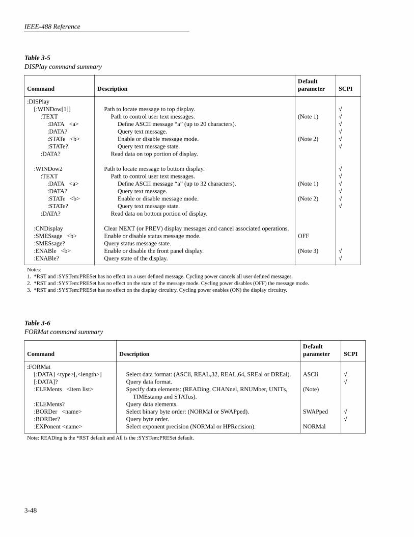
IEEE-488 Reference
3-48
Table 3-5
DISPlay command summary
Command DescriptionDefault parameter SCPI
:DISPlay[:WINDow[1]]
:TEXT:DATA <a>:DATA?:STATe <b>:STATe?
:DATA?
:WINDow2:TEXT
:DATA <a>:DATA?:STATe <b>:STATe?
:DATA?
:CNDisplay:SMESsage <b>:SMESsage?:ENABle <b>:ENABle?
Path to locate message to top display.Path to control user text messages.
Define ASCII message “a” (up to 20 characters).Query text message.Enable or disable message mode.Query text message state.
Read data on top portion of display.
Path to locate message to bottom display.Path to control user text messages.
Define ASCII message “a” (up to 32 characters).Query text message.Enable or disable message mode.Query text message state.
Read data on bottom portion of display.
Clear NEXT (or PREV) display messages and cancel associated operations.Enable or disable status message mode.Query status message state. Enable or disable the front panel display.Query state of the display.
(Note 1)
(Note 2)
(Note 1)
(Note 2)
OFF
(Note 3)
√
√
√
√
√
√
√
√
√
√
√
√
√
√
Notes:1. *RST and :SYSTem:PRESet has no effect on a user defined message. Cycling power cancels all user defined messages.2. *RST and :SYSTem:PRESet has no effect on the state of the message mode. Cycling power disables (OFF) the message mode.3. *RST and :SYSTem:PRESet has no effect on the display circuitry. Cycling power enables (ON) the display circuitry.
Table 3-6
FORMat command summary
Command DescriptionDefault parameter SCPI
:FORMat[:DATA] <type>[,<length>][:DATA]?:ELEMents <item list>
:ELEMents?:BORDer <name>:BORDer?:EXPonent <name>
Select data format: (ASCii, REAL,32, REAL,64, SREal or DREal).Query data format.Specify data elements: (READing, CHANnel, RNUMber, UNITs,
TIMEstamp and STATus).Query data elements.Select binary byte order: (NORMal or SWAPped).Query byte order.Select exponent precision (NORMal or HPRecision).
ASCii
(Note)
SWAPped
NORMal
√
√
√
√
Note: READing is the *RST default and All is the :SYSTem:PRESet default.
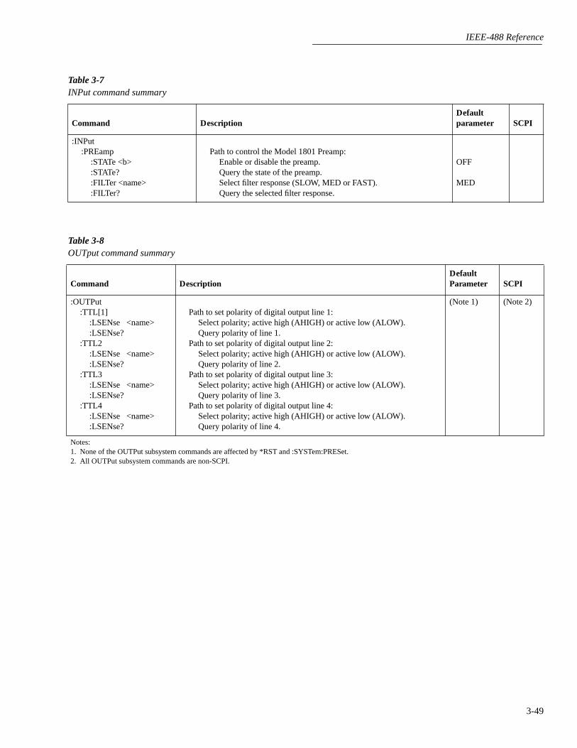
IEEE-488 Reference
3-49
Table 3-7
INPut command summary
Command DescriptionDefault parameter SCPI
:INPut:PREamp
:STATe <b>:STATe?:FILTer <name>:FILTer?
Path to control the Model 1801 Preamp:Enable or disable the preamp.Query the state of the preamp.Select filter response (SLOW, MED or FAST).Query the selected filter response.
OFF
MED
Table 3-8
OUTput command summary
Command DescriptionDefault Parameter SCPI
:OUTPut:TTL[1]
:LSENse <name>:LSENse?
:TTL2:LSENse <name>:LSENse?
:TTL3:LSENse <name>:LSENse?
:TTL4:LSENse <name>:LSENse?
Path to set polarity of digital output line 1:Select polarity; active high (AHIGH) or active low (ALOW).Query polarity of line 1.
Path to set polarity of digital output line 2:Select polarity; active high (AHIGH) or active low (ALOW).Query polarity of line 2.
Path to set polarity of digital output line 3:Select polarity; active high (AHIGH) or active low (ALOW).Query polarity of line 3.
Path to set polarity of digital output line 4:Select polarity; active high (AHIGH) or active low (ALOW).Query polarity of line 4.
(Note 1) (Note 2)
Notes:1. None of the OUTPut subsystem commands are affected by *RST and :SYSTem:PRESet.2. All OUTPut subsystem commands are non-SCPI.
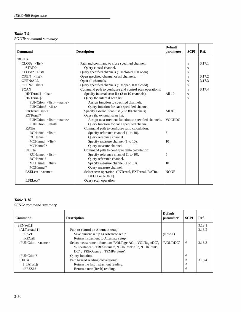
IEEE-488 Reference
3-50
Table 3-9
ROUTe command summary
Command DescriptionDefault parameter SCPI Ref.
:ROUTe:CLOSe <list>
:STATe?:CLOSe? <list>:OPEN <list>:OPEN:ALL:OPEN? <list>:SCAN
[:INTernal] <list>[:INTernal]?
:FUNCtion <list>, <name>:FUNCtion? <list>
:EXTernal <list>:EXTernal?
:FUNCtion <list>, <name>:FUNCtion? <list>
:RATio:RCHannel <list>:RCHannel?:MCHannel <list>:MCHannel?
:DELTa:RCHannel <list>:RCHannel?:MCHannel <list>:MCHannel?
:LSELect <name>
:LSELect?
Path and command to close specified channel:Query closed channel.
Query specified channels (1 = closed, 0 = open).Open specified channel or all channels.Open all channels.Query specified channels (1 = open, 0 = closed).Command path to configure and control scan operations:
Specify internal scan list (2 to 10 channels).Query the internal scan list.
Assign function to specified channels.Query function for each specified channel.
Specify external scan list (2 to 80 channels).Query the external scan list.
Assign measurement function to specified channels.Query function for each specified channel.
Command path to configure ratio calculation:Specify reference channel (1 to 10).Query reference channel.Specify measure channel (1 to 10).Query measure channel.
Command path to configure delta calculation:Specify reference channel (1 to 10).Query reference channel.Specify measure channel (1 to 10).Query measure channel.
Select scan operation: (INTernal, EXTernal, RATio,DELTa or NONE).
Query scan operation.
All 10
All 80
VOLT:DC
5
10
5
10
NONE
√
√
√
√
√
√
√
√
√
3.17.1
3.17.23.17.3
3.17.4
Table 3-10
SENSe command summary
Command DescriptionDefault parameter SCPI Ref.
[:SENSe[1]]:ALTernate[1]
:SAVE:RECall
:FUNCtion <name>
:FUNCtion?:DATA
[:LATest]?:FRESh?
Path to control an Alternate setup.Save current setup as Alternate setup.Return instrument to Alternate setup.
Select measurement function: ‘VOLTage:AC’, ‘VOLTage:DC’, ‘RESistance’, ‘FRESistance’, ‘CURRent:AC’, ‘CURRent:DC’ , ‘FREQuency’,‘TEMPerature’
Query function.Path to read reading conversions:
Return the last instrument reading.Return a new (fresh) reading.
(Note 1)
‘VOLT:DC’
√
√
√
√
√
3.18.13.18.2
3.18.3
3.18.4
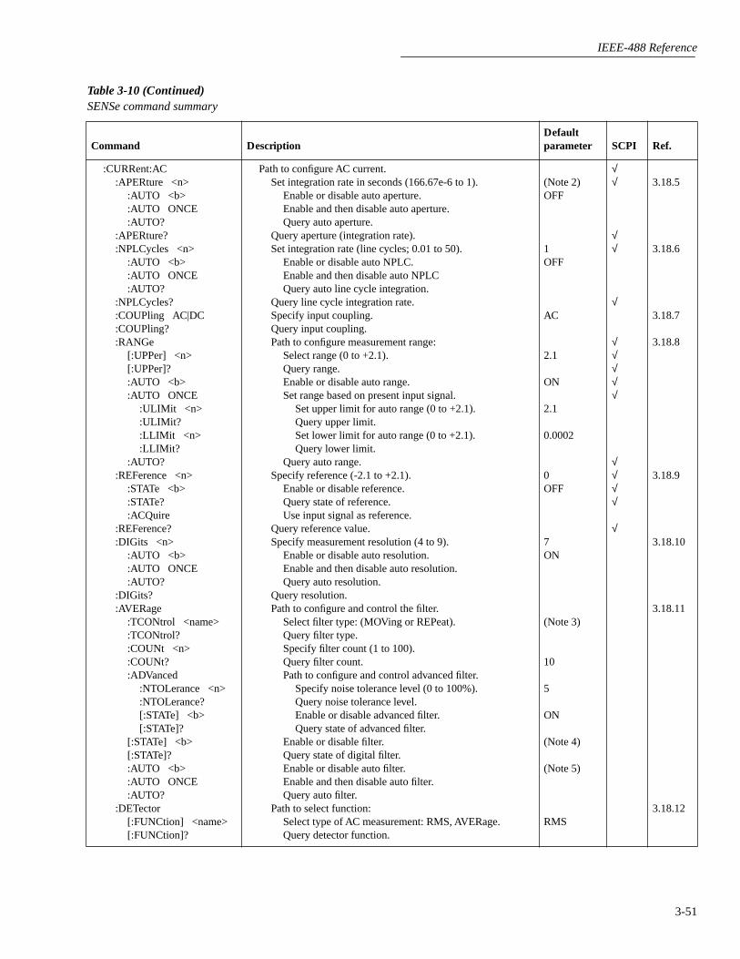
IEEE-488 Reference
3-51
:CURRent:AC:APERture <n>
:AUTO <b>:AUTO ONCE:AUTO?
:APERture?:NPLCycles <n>
:AUTO <b>:AUTO ONCE:AUTO?
:NPLCycles?:COUPling AC|DC:COUPling?:RANGe
[:UPPer] <n>[:UPPer]?:AUTO <b>:AUTO ONCE
:ULIMit <n>:ULIMit?:LLIMit <n>:LLIMit?
:AUTO?:REFerence <n>
:STATe <b>:STATe?:ACQuire
:REFerence?:DIGits <n>
:AUTO <b>:AUTO ONCE:AUTO?
:DIGits?:AVERage
:TCONtrol <name>:TCONtrol?:COUNt <n>:COUNt?:ADVanced
:NTOLerance <n>:NTOLerance?[:STATe] <b>[:STATe]?
[:STATe] <b>[:STATe]?:AUTO <b>:AUTO ONCE:AUTO?
:DETector[:FUNCtion] <name>[:FUNCtion]?
Path to configure AC current.Set integration rate in seconds (166.67e-6 to 1).
Enable or disable auto aperture.Enable and then disable auto aperture.Query auto aperture.
Query aperture (integration rate).Set integration rate (line cycles; 0.01 to 50).
Enable or disable auto NPLC.Enable and then disable auto NPLCQuery auto line cycle integration.
Query line cycle integration rate.Specify input coupling.Query input coupling.Path to configure measurement range:
Select range (0 to +2.1).Query range.Enable or disable auto range.Set range based on present input signal.
Set upper limit for auto range (0 to +2.1).Query upper limit.Set lower limit for auto range (0 to +2.1).Query lower limit.
Query auto range.Specify reference (-2.1 to +2.1).
Enable or disable reference.Query state of reference.Use input signal as reference.
Query reference value.Specify measurement resolution (4 to 9).
Enable or disable auto resolution.Enable and then disable auto resolution.Query auto resolution.
Query resolution.Path to configure and control the filter.
Select filter type: (MOVing or REPeat).Query filter type.Specify filter count (1 to 100).Query filter count.Path to configure and control advanced filter.
Specify noise tolerance level (0 to 100%).Query noise tolerance level.Enable or disable advanced filter.Query state of advanced filter.
Enable or disable filter.Query state of digital filter.Enable or disable auto filter.Enable and then disable auto filter.Query auto filter.
Path to select function:Select type of AC measurement: RMS, AVERage.Query detector function.
(Note 2)OFF
1OFF
AC
2.1
ON
2.1
0.0002
0OFF
7ON
(Note 3)
10
5
ON
(Note 4)
(Note 5)
RMS
√
√
√
√
√
√
√
√
√
√
√
√
√
√
√
3.18.5
3.18.6
3.18.7
3.18.8
3.18.9
3.18.10
3.18.11
3.18.12
Table 3-10 (Continued)
SENSe command summary
Command DescriptionDefault parameter SCPI Ref.

IEEE-488 Reference
3-52
:CURRent:DC:APERture <n>
:AUTO <b>:AUTO ONCE:AUTO?
:APERture?:NPLCycles <n>
:AUTO <b>:AUTO ONCE:AUTO?
:NPLCycles?:RANGe
[:UPPer] <n>[:UPPer]?:AUTO <b>:AUTO ONCE
:ULIMit <n>:ULIMit?:LLIMit <n>:LLIMit?
:AUTO?:REFerence <n>
:STATe <b>:STATe?:ACQuire
:REFerence?:DIGits <n>
:AUTO <b>:AUTO ONCE:AUTO?
:DIGits?:AVERage
:TCONtrol <name>:TCONtrol?:COUNt <n>:COUNt?:ADVanced
:NTOLerance <n>:NTOLerance?[:STATe] <b>[:STATe]?
[:STATe] <b>[:STATe]?:AUTO <b>:AUTO ONCE:AUTO?
:METHod <name>:METHod?
Path to configure DC current.Set integration rate in seconds (166.67e-6 to 1).
Enable or disable auto aperture.Enable and then disable auto aperture.Query auto aperture.
Query aperture (integration rate).Set integration rate (line cycles; 0.01 to 50).
Enable or disable auto NPLC.Enable and then disable auto NPLC.Query auto line cycle integration.
Query line cycle integration rate.Path to configure measurement range:
Select range (0 to 2.1).Query range.Enable or disable auto range.Set range based on present input signal.
Set upper limit for auto range (0 to 2.1).Query upper limit.Set lower limit for auto range (0 to 2.1).Query lower limit.
Query auto range.Specify reference (-2.1 to +2.1).
Enable or disable reference.Query state of reference.Use input signal as reference.
Query reference value.Specify measurement resolution (4 to 9).
Enable or disable auto resolution.Enable and then disable auto resolution.Query auto resolution (0 or 1).
Query resolution.Path to configure and control the filter.
Select filter type: (MOVing or REPeat).Query filter type.Specify filter count (1 to 100).Query filter count.Path to configure and control advanced filter.
Specify noise tolerance level (0 to 100%).Query noise tolerance level.Enable or disable advanced filter.Query state of advanced filter.
Enable or disable filter.Query state of digital filter.Enable or disable auto filter.Enable and then disable auto filter.Query auto filter.
Select measure technique: (NORMal or ICIRcuit).Query method.
(Note 2)OFF
1OFF
2.1
ON
2.1
0.0002
0OFF
7ON
(Note 3)
10
1
ON
(Note 4)
(Note 5)
NORMal
√
√
√
√
√
√
√
√
√
√
√
√
√
√
√
3.18.5
3.18.6
3.18.8
3.18.9
3.18.10
3.18.11
3.18.14
Table 3-10 (Continued)
SENSe command summary
Command DescriptionDefault parameter SCPI Ref.

IEEE-488 Reference
3-53
:VOLTage:AC:APERture <n>
:AUTO <b>:AUTO ONCE:AUTO?
:APERture?:NPLCycles <n>
:AUTO <b>:AUTO ONCE:AUTO?
:NPLCycles?:COUPling AC|DC:COUPling?:RANGe
[:UPPer] <n>[:UPPer]?:AUTO <b>:AUTO ONCE
:ULIMit <n>:ULIMit?:LLIMit <n>:LLIMit?
:AUTO?:REFerence <n>
:STATe <b>:STATe?:ACQuire
:REFerence?:DIGits <n>
:AUTO <b>:AUTO ONCE:AUTO?
:DIGits?:AVERage
:TCONtrol <name>:TCONtrol?:COUNt <n>:COUNt?:ADVanced
:NTOLerance <n>:NTOLerance?[:STATe] <b>[:STATe]?
[:STATe] <b>[:STATe]?:AUTO <b>:AUTO ONCE:AUTO?
Path to configure AC voltage.Set integration rate in seconds (166.67e-6 to 1).
Enable or disable auto aperture.Enable and then disable auto aperture.Query auto aperture.
Query aperture (integration rate).Set integration rate (line cycles; 0.01 to 50).
Enable or disable auto NPLC.Enable and then disable auto NPLC.Query auto line cycle integration.
Query line cycle integration rate.Specify input coupling.Query input coupling.Path to configure measurement range:
Select range (0 to +775).Query range.Enable or disable auto range.Set range based on present input signal.
Set upper limit for auto range (0 to +775).Query upper limit.Set lower limit for auto range (0 to +775).Query lower limit.
Query auto range.Specify reference (-1100 to 1100).
Enable or disable reference.Query state of reference.Use input signal as reference.
Query reference value.Specify measurement resolution (4 to 9).
Enable or disable auto resolution.Enable and then disable auto resolution.Query auto resolution.
Query resolution.Path to configure and control the filter.
Select filter type: (MOVing or REPeat).Query filter type.Specify filter count (1 to 100).Query filter count.Path to configure and control advanced filter.
Specify noise tolerance level (0 to 100%).Query noise tolerance level.Enable or disable advanced filter.Query state of advanced filter.
Enable or disable filter.Query state of digital filter.Enable or disable auto filter.Enable and then disable auto filter.Query auto filter.
(Note 2)OFF
1OFF
AC
775
ON
775
0.2
0OFF
6ON
(Note 3)
10
5
ON
(Note 4)
(Note 5)
√
√
√
√
√
√
√
√
√
√
√
√
√
√
√
3.18.5
3.18.6
3.18.7
3.18.8
3.18.9
3.18.10
3.18.11
Table 3-10 (Continued)
SENSe command summary
Command DescriptionDefault parameter SCPI Ref.

IEEE-488 Reference
3-54
:VOLTage:AC
:DETector[:FUNCtion] <name>
[:FUNCtion]?:PWINdow <n>:PWINdow?
Path to select AC type:Select type of AC measurement: RMS, AVERage,
PEAK, LFRMs, NPEak, PPEak.Query detector function.Specify window in seconds (0.1 to 9.9).Query peak spike detection window.
RMS
0.1
3.18.12
3.18.13
:VOLTage:DC:APERture <n>
:AUTO <b>:AUTO ONCE:AUTO?
:APERture?:NPLCycles <n>
:AUTO <b>:AUTO ONCE:AUTO?
:NPLCycles?:RANGe
[:UPPer] <n>[:UPPer]?:AUTO <b>:AUTO ONCE
:ULIMit <n>:ULIMit?:LLIMit <n>:LLIMit?
:AUTO?:REFerence <n>
:STATe <b>:STATe?:ACQuire
:REFerence?:DIGits <n>
:AUTO <b>:AUTO ONCE:AUTO?
:DIGits?:AVERage
:TCONtrol <name>:TCONtrol?:COUNt <n>:COUNt?:ADVanced
:NTOLerance <n>:NTOLerance?[:STATe] <b>[:STATe]?
[:STATe] <b>[:STATe]?:AUTO <b>:AUTO ONCE:AUTO?
Path to configure DC voltage:Set integration rate in seconds (166.67e-6 to 1).
Enable or disable auto aperture.Enable and then disable auto aperture.Query auto aperture.
Query aperture (integration rate).Set integration rate (line cycles; (0.01 to 50).
Enable or disable auto NPLC.Enable and then disable auto NPLC.Query auto line cycle integration.
Query line cycle integration rate.Path to configure measurement range:
Select range (0 to 1100).Query range.Enable or disable auto range.Set range based on present input signal.
Set upper limit for auto range (0 to 1100).Query upper limit.Set lower limit for auto range (0 to 1100).Query lower limit.
Query auto range.Specify reference (-1100 to +1100).
Enable or disable reference.Query state of reference (0 or 1).Use input signal as reference.
Query reference value.Specify measurement resolution (4 to 9).
Enable or disable auto resolution.Enable and then disable auto resolution.Query auto resolution.
Query resolution.Path to configure and control the filter.
Select filter type: (MOVing or REPeat).Query filter type.Specify filter count (1 to 100).Query filter count.Path to configure and control advanced filter.
Specify noise tolerance level (0 to 100%).Query noise tolerance level.Enable or disable advanced filter.Query state of advanced filter.
Enable or disable filter.Query state of digital filter.Enable or disable auto filter.Enable and then disable auto filter.Query auto filter.
(Note 2)OFF
1OFF
1100
ON
1100
0.2
0OFF
8ON
(Note 3)
10
1
ON
(Note 4)
(Note 5)
√
√
√
√
√
√
√
√
√√
√√√√
√
3.18.5
3.18.6
3.18.8
3.18.9
3.18.10
3.18.11
Table 3-10 (Continued)SENSe command summary
Command DescriptionDefault parameter SCPI Ref.
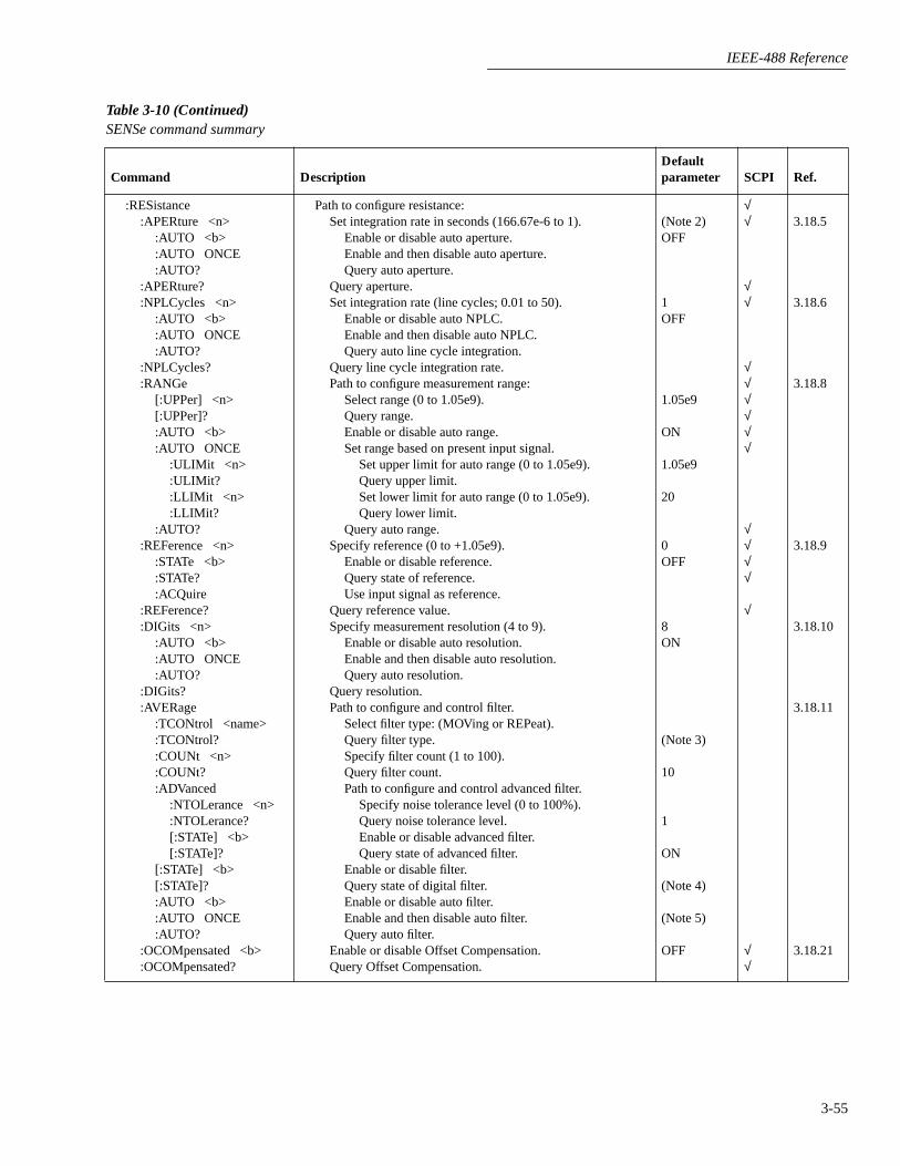
IEEE-488 Reference
3-55
:RESistance:APERture <n>
:AUTO <b>:AUTO ONCE:AUTO?
:APERture?:NPLCycles <n>
:AUTO <b>:AUTO ONCE:AUTO?
:NPLCycles?:RANGe
[:UPPer] <n>[:UPPer]?:AUTO <b>:AUTO ONCE
:ULIMit <n>:ULIMit?:LLIMit <n>:LLIMit?
:AUTO?:REFerence <n>
:STATe <b>:STATe?:ACQuire
:REFerence?:DIGits <n>
:AUTO <b>:AUTO ONCE:AUTO?
:DIGits?:AVERage
:TCONtrol <name>:TCONtrol?:COUNt <n>:COUNt?:ADVanced
:NTOLerance <n>:NTOLerance?[:STATe] <b>[:STATe]?
[:STATe] <b>[:STATe]?:AUTO <b>:AUTO ONCE:AUTO?
:OCOMpensated <b>:OCOMpensated?
Path to configure resistance:Set integration rate in seconds (166.67e-6 to 1).
Enable or disable auto aperture.Enable and then disable auto aperture.Query auto aperture.
Query aperture.Set integration rate (line cycles; 0.01 to 50).
Enable or disable auto NPLC.Enable and then disable auto NPLC.Query auto line cycle integration.
Query line cycle integration rate.Path to configure measurement range:
Select range (0 to 1.05e9).Query range.Enable or disable auto range.Set range based on present input signal.
Set upper limit for auto range (0 to 1.05e9).Query upper limit.Set lower limit for auto range (0 to 1.05e9).Query lower limit.
Query auto range.Specify reference (0 to +1.05e9).
Enable or disable reference.Query state of reference.Use input signal as reference.
Query reference value.Specify measurement resolution (4 to 9).
Enable or disable auto resolution.Enable and then disable auto resolution.Query auto resolution.
Query resolution.Path to configure and control filter.
Select filter type: (MOVing or REPeat).Query filter type.Specify filter count (1 to 100).Query filter count.Path to configure and control advanced filter.
Specify noise tolerance level (0 to 100%).Query noise tolerance level.Enable or disable advanced filter.Query state of advanced filter.
Enable or disable filter.Query state of digital filter.Enable or disable auto filter.Enable and then disable auto filter.Query auto filter.
Enable or disable Offset Compensation.Query Offset Compensation.
(Note 2)OFF
1OFF
1.05e9
ON
1.05e9
20
0OFF
8ON
(Note 3)
10
1
ON
(Note 4)
(Note 5)
OFF
√√
√√
√√√√√√
√√√√
√
√√
3.18.5
3.18.6
3.18.8
3.18.9
3.18.10
3.18.11
3.18.21
Table 3-10 (Continued)SENSe command summary
Command DescriptionDefault parameter SCPI Ref.
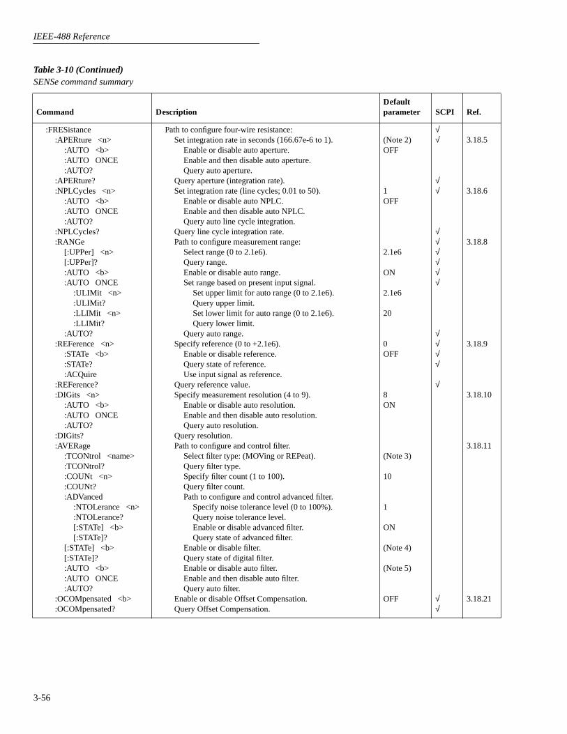
IEEE-488 Reference
3-56
:FRESistance:APERture <n>
:AUTO <b>:AUTO ONCE:AUTO?
:APERture?:NPLCycles <n>
:AUTO <b>:AUTO ONCE:AUTO?
:NPLCycles?:RANGe
[:UPPer] <n>[:UPPer]?:AUTO <b>:AUTO ONCE
:ULIMit <n>:ULIMit?:LLIMit <n>:LLIMit?
:AUTO?:REFerence <n>
:STATe <b>:STATe?:ACQuire
:REFerence?:DIGits <n>
:AUTO <b>:AUTO ONCE:AUTO?
:DIGits?:AVERage
:TCONtrol <name>:TCONtrol?:COUNt <n>:COUNt?:ADVanced
:NTOLerance <n>:NTOLerance?[:STATe] <b>[:STATe]?
[:STATe] <b>[:STATe]?:AUTO <b>:AUTO ONCE:AUTO?
:OCOMpensated <b>:OCOMpensated?
Path to configure four-wire resistance:Set integration rate in seconds (166.67e-6 to 1).
Enable or disable auto aperture.Enable and then disable auto aperture.Query auto aperture.
Query aperture (integration rate).Set integration rate (line cycles; 0.01 to 50).
Enable or disable auto NPLC.Enable and then disable auto NPLC.Query auto line cycle integration.
Query line cycle integration rate.Path to configure measurement range:
Select range (0 to 2.1e6).Query range.Enable or disable auto range.Set range based on present input signal.
Set upper limit for auto range (0 to 2.1e6).Query upper limit.Set lower limit for auto range (0 to 2.1e6).Query lower limit.
Query auto range.Specify reference (0 to +2.1e6).
Enable or disable reference.Query state of reference.Use input signal as reference.
Query reference value.Specify measurement resolution (4 to 9).
Enable or disable auto resolution.Enable and then disable auto resolution.Query auto resolution.
Query resolution.Path to configure and control filter.
Select filter type: (MOVing or REPeat).Query filter type.Specify filter count (1 to 100).Query filter count.Path to configure and control advanced filter.
Specify noise tolerance level (0 to 100%).Query noise tolerance level.Enable or disable advanced filter.Query state of advanced filter.
Enable or disable filter.Query state of digital filter.Enable or disable auto filter.Enable and then disable auto filter.Query auto filter.
Enable or disable Offset Compensation.Query Offset Compensation.
(Note 2)OFF
1OFF
2.1e6
ON
2.1e6
20
0OFF
8ON
(Note 3)
10
1
ON
(Note 4)
(Note 5)
OFF
√√
√√
√√√√√√
√√√√
√
√√
3.18.5
3.18.6
3.18.8
3.18.9
3.18.10
3.18.11
3.18.21
Table 3-10 (Continued)SENSe command summary
Command DescriptionDefault parameter SCPI Ref.

IEEE-488 Reference
3-57
:FREQuency:COUPling AC|DC:COUPling?:REFerence <n>
:STATe <b>:STATe?:ACQuire
:REFerence?:DIGits <n>:DIGits?:SOURce <name>:SOURce?:THReshold
:CURRent:RANGe <n>:RANGe?:LEVel <n>:LEVel?
:VOLTage:RANGe <n>:RANGe?:LEVel <n>:LEVel?:TTL
Path to configure frequency:Specify input coupling.Query input coupling.Specify reference (0 to 15e6).
Enable or disable reference.Query state of reference.Use input signal as reference.
Query reference value.Specify measurement resolution (4 or 5).Query resolution.Select source: (CURRent or VOLTage).Query source.Path to configure threshold:
Path to set current threshold:Specify range (0 to 1).Query range.Specify threshold level.Query threshold level.
Path to set voltage threshold:Specify range (0 to 1000).Query range.Specify threshold level.Query threshold level.Set threshold to TTL level.
AC
0OFF
5
VOLTage
0.001
0
10
0
3.18.7
3.18.9
3.18.10
3.18.15
3.18.16
:TEMPerature:APERture <n>
:AUTO <b>:AUTO ONCE:AUTO?
:APERture?:NPLCycles <n>
:AUTO <b>:AUTO ONCE:AUTO?
:NPLCycles?:REFerence <n>
:STATe <b>:STATe?:ACQuire
:REFerence?:DIGits <n>
:AUTO <b>:AUTO ONCE:AUTO?
:DIGits?
Path to configure four-wire resistance:Set integration rate in seconds (166.67e-6 to 1).
Enable or disable auto aperture.Enable and then disable auto aperture.Query auto aperture.
Query aperture (integration rate).Set integration rate (line cycles; 0.01 to 50).
Enable or disable auto NPLC.Enable and then disable auto NPLC.Query auto line cycle integration.
Query line cycle integration rate.Specify reference; -200 to +1821 (°C)
Enable or disable reference.Query state of reference.Use input signal as reference.
Query reference value.Specify measurement resolution (4 to 7).
Enable or disable auto resolution.Enable and then disable auto resolution.Query auto resolution.
Query resolution.
(Note 2)OFF
1OFF
0OFF
6ON
3.18.5
3.18.6
3.18.9
3.18.10
Table 3-10 (Continued)SENSe command summary
Command DescriptionDefault parameter SCPI Ref.
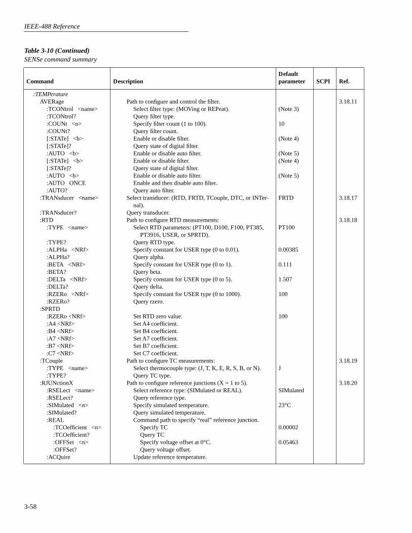
IEEE-488 Reference
3-58
:TEMPeratureAVERage
:TCONtrol <name>:TCONtrol?:COUNt <n>:COUNt?[:STATe] <b>[:STATe]?:AUTO <b>[:STATe] <b>[:STATe]?:AUTO <b>:AUTO ONCE:AUTO?
:TRANsducer <name>
:TRANsducer?:RTD
:TYPE <name>
:TYPE?:ALPHa <NRf>:ALPHa?:BETA <NRf>:BETA?:DELTa <NRf>:DELTa?:RZERo <NRf>:RZERo?
:SPRTD:RZERo <NRf>:A4 <NRf>:B4 <NRf>:A7 <NRf>:B7 <NRf>:C7 <NRf>
:TCouple:TYPE <name>:TYPE?
:RJUNctionX:RSELect <name>:RSELect?:SIMulated <n>:SIMulated?:REAL
:TCOefficient <n>:TCOefficient?:OFFSet <n>:OFFSet?
:ACQuire
Path to configure and control the filter.Select filter type: (MOVing or REPeat).Query filter type.Specify filter count (1 to 100).Query filter count.Enable or disable filter.Query state of digital filter.Enable or disable auto filter.Enable or disable filter.Query state of digital filter.Enable or disable auto filter.Enable and then disable auto filter.Query auto filter.
Select transducer: (RTD, FRTD, TCouple, DTC, or INTer-nal).
Query transducer.Path to configure RTD measurements:
Select RTD parameters: (PT100, D100, F100, PT385, PT3916, USER, or SPRTD).
Query RTD type.Specify constant for USER type (0 to 0.01).Query alpha.Specify constant for USER type (0 to 1).Query beta.Specify constant for USER type (0 to 5).Query delta.Specify constant for USER type (0 to 1000).Query rzero.
Set RTD zero value.Set A4 coefficient.Set B4 coefficient.Set A7 coefficient.Set B7 coefficient.Set C7 coefficient.
Path to configure TC measurements:Select thermocouple type: (J, T, K, E, R, S, B, or N).Query TC type.
Path to configure reference junctions (X = 1 to 5).Select reference type: (SIMulated or REAL).Query reference type.Specify simulated temperature.Query simulated temperature.Command path to specify “real” reference junction.
Specify TCQuery TCSpecify voltage offset at 0°C.Query voltage offset.
Update reference temperature.
(Note 3)
10
(Note 4)
(Note 5)(Note 4)
(Note 5)
FRTD
PT100
0.00385
0.111
1.507
100
100
J
SIMulated
23°C
0.00002
0.05463
3.18.11
3.18.17
3.18.18
3.18.19
3.18.20
Table 3-10 (Continued)SENSe command summary
Command DescriptionDefault parameter SCPI Ref.

IEEE-488 Reference
3-59
:TEMPerature:DTCouple
:TYPE <type>
:TYPE:USLope <n>
:USLope?
:RTEMperature <n>
:RTEMperature?
Differential path.Select thermocouple type (<type> = J|K|T\E\R\S\B\N
USER).Return thermocouple type (J\K\T\R\R\S\B\N\ USER).Select thermocouple slope (<n> = slope in V/°C, 0 is
invalid).Return thermocouple slope (V/°C min = -0.099999; max
= 0.099999; default = 20E-6).Select reference thermocouple temperature (<n> = refer-
ence temperature in degrees)Return thermocouple reference temperature in degrees;
min = -273°C; max = 2000°C; default = 0°C).
3.18.22
:SENSe2:TTL[1]
:DATA?Path to read digital input port:
Query (read) the digital input port.
3.18.23
Notes:1. The saved alternate setup is lost when power is cycled, or if *RST or :SYSTem:PRESet is sent over the bus.2. The default parameter is power line cycle integration; 16.67msec for 60Hz power line and 20msec for 50Hz or 400Hz power line.3. REPeat is the *RST default parameter and MOVing is the :SYSTem:PRESet default parameter.4. The *RST default parameter is OFF for all functions. The :SYSTem:PRESet default is OFF for ACI, ACV and TEMP, and ON for DCI, DCV, Ω2 and
Ω4.5. The *RST default parameter is OFF for all functions. The :SYSTem:PRESet default parameter is ON for ACI, DCI, ACV, DCV, Ω2 and Ω4, and OFF for
TEMP.
Table 3-11 SOURce command summary
Command DescriptionDefault parameter SCPI
:SOURce:TTL[1][:LEVel] <b>:TTL[1][:LEVel]?:TTL2[:LEVel] <b>:TTL2[:LEVel]?:TTL3[:LEVel] <b>:TTL3[:LEVel]?:TTL4[:LEVel] <b>:TTL4[:LEVel]?
Set digital output line #1 true (1 or ON) or false (0 or OFF).Query digital output line 1.Set digital output line #2 true (1 or ON) or false (0 or OFF).Query digital output line 2.Set digital output line #3 true (1 or ON) or false (0 or OFF).Query digital output line 3.Set digital output line #4 true (1 or ON) or false (0 or OFF).Query digital output line 4.
(Note 1) (Note 2)
Notes:1. *RST and :SYSTem:PRESet have no affect on the state of the output lines. However, cycling power sets all output lines false (OFF).2. All :SOURce subsystem commands are non-SCPI.
Table 3-10 (Continued)SENSe command summary
Command DescriptionDefault parameter SCPI Ref.
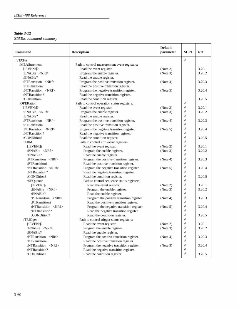
IEEE-488 Reference
3-60
Table 3-12 STATus command summary
Command DescriptionDefault parameter SCPI Ref.
:STATus:MEASurement
[:EVENt]?:ENABle <NRf>:ENABle?:PTRansition <NRf>:PTRansition?:NTRansition <NRf>:NTRansition?:CONDition?
:OPERation[:EVENt]?:ENABle <NRf>:ENABle?:PTRansition <NRf>:PTRansition?:NTRansition <NRf>:NTRansition?:CONDition?:ARM
[:EVENt]?:ENABle <NRf>:ENABle?:PTRansition <NRf>:PTRansition?:NTRansition <NRf>:NTRansition?:CONDition?:SEQuence
[:EVENt]?:ENABle <NRf>:ENABle?:PTRansition <NRf>:PTRansition?:NTRansition <NRf>:NTRansition?:CONDition?
:TRIGger[:EVENt]?:ENABle <NRf>:ENABle?:PTRansition <NRf>:PTRansition?:NTRansition <NRf>:NTRansition?:CONDition?
Path to control measurement event registers:Read the event register.Program the enable register.Read the enable register.Program the positive transition register. Read the positive transition register.Program the negative transition register.Read the negative transition register.Read the condition register.
Path to control operation status registers:Read the event register.Program the enable register.Read the enable register.Program the positive transition register.Read the positive transition register.Program the negative transition register.Read the negative transition register.Read the condition register.Path to control arm event registers:
Read the event register.Program the enable register.Read the enable register.Program the positive transition register.Read the positive transition register.Program the negative transition register.Read the negative transition register.Read the condition register.Path to control sequence status registers:
Read the event register.Program the enable register.Read the enable register.Program the positive transition register.Read the positive transition register.Program the negative transition register.Read the negative transition register.Read the condition register.
Path to control trigger status registers:Read the event register.Program the enable register.Read the enable register.Program the positive transition register.Read the positive transition register.Program the negative transition register.Read the negative transition register.Read the condition register.
(Note 2)(Note 3)
(Note 4)
(Note 5)
(Note 2)(Note 3)
(Note 4)
(Note 5)
(Note 2)(Note 3)
(Note 4)
(Note 5)
(Note 2)(Note 3)
(Note 4)
(Note 5)
(Note 2)(Note 3)
(Note 4)
(Note 5)
√
√√√√√√√√√√√√√√√√√√√√√√√√√√√√√√√√√√√√
3.20.13.20.2
3.20.3
3.20.4
3.20.5
3.20.13.20.2
3.20.3
3.20.4
3.20.5
3.20.13.20.2
3.20.3
3.20.4
3.20.5
3.20.13.20.2
3.20.3
3.20.4
3.20.5
3.20.13.20.2
3.20.3
3.20.4
3.20.5

IEEE-488 Reference
3-61
:STATus:QUEStionable
[:EVENt]?:ENABle <NRf>:ENABle?:PTRansition <NRf>:PTRansition?:NTRansition <NRf>:NTRansition?:CONDition?
:PRESet:QUEue
[:NEXT]?:ENABle <list>:ENABle?:DISable <list>:DISable?:CLEar
Path to control questionable status registers:Read the event register.Program the enable register.Read the enable register.Program the positive transition register.Read the positive transition register.Program the negative transition register.Read the negative transition register.Read the condition register.
Return status registers to default states.Path to access error queue:
Read the most recent error message.Specify error and status messages for queue.Read the enabled messages.Specify messages not to be placed in queue.Read the disabled messages.Clears all messages from Error Queue.
(Note 2)(Note 3)
(Note 4)
(Note 5)
(Note 6)(Note 7)
(Note 7)
√√√√√√√√√√√√√√
3.20.13.20.2
3.20.3
3.20.4
3.20.53.20.63.20.7
Notes:1. Commands in this subsystem are not affected by *RST and :SYSTem:PRESet. The effects of cycling power, *CLS and :STATus:PRESet are explained
by the following notes.2. Event Registers: Power-up and *CLS – Clears all bits of the registers
:STATus:PRESet – No effect.3. Enable Registers: Power-up and :STATus:PRESet – Clears all bits of the registers
*CLS – No effect4. PTR Registers: Power-up and :STATus:PRESet sets all bits of the registers
*CLS – No effect5. NTR Registers: Power-up and :STATus:PRESet clears all bits of the registers
*CLS – No effect6. Error Queue: Power-up and *CLS – Clears the Error Queue
:STATus:PRESet – No effect7. Enable/Disable Error Queue Messages: Power-up – Clears list of messages
*CLS and :STATus:PRESet – No effect
Table 3-12 (Continued)STATus command summary
Command DescriptionDefault parameter SCPI Ref.

IEEE-488 Reference
3-62
Table 3-13 SYSTem command summary
Command DescriptionDefault parameter SCPI Ref
:SYSTem:PRESet:POSetup <name>:POSetup?:FRSWitch?:VERSion?:ERRor?:AZERo
:TYPE <name>:TYPE?:STATe <b>:STATe?
:AMEThod <name>
:AMEThod?:LSYNc
:STATe <b>:STATe?
:KEY <NRf>:KEY?:CLEar:LFRequency?:DATE <yr>, <mo>, <day>:DATE?:TIME <hr>, <min>, <sec>:TIME?:TSTamp
:TYPE <name>:TYPE?
:RELative:RESet
:RNUMber:RESet
Return to :SYST:PRES defaults.Select power-on setup: (RST, PRESet or SAV0-SAV9).Query power-on setup.Query INPUTS switch (0 = rear, 1 = front).Query rev level of SCPI standard.Query (read) Error Queue. Path to set up autozero.
Select autozero mode: (NORMal or SYNChronous).Query autozero mode.Enable or disable autozero.Query autozero.
Select reading acquisition method: (BURSt, NORMal, ASTReam or SSTReam).
Query acquisition method.Path to control line synchronization of measurements.
Enable or disable line sync.Query line sync.
Simulate key-press (1 to 31; see Figure 3-39).Query the last “pressed” key.Clears messages from the Error Queue.Query frequency of line power.Set date.Query date.Set time (24-hour format).Query time.Path to configure and control timestamp.
Select timestamp type (RELative or RTClock).Query timestamp type.
Path to reset timestamp.Reset relative timestamp to 0 sec.
Path to reset reading number.Reset reading number ot zero.
(Note)
SYNC
ON
NORMal
OFF
√
√√
√√
3.21.13.21.2
3.21.33.21.43.21.53.21.6
3.21.7
3.21.8
3.21.9
3.21.103.21.113.21.12
3.21.13
3.21.14
3.21.15
Note: Clearing the Error Queue: Power-up and *CLS – Clears the Error Queue*RST, :SYSTem:PRESet and :STATus:PRESet – No effect

IEEE-488 Reference
3-63
Table 3-14 TRACe command summary
Command DescriptionPower-up defaults* SCPI Ref.
:TRACe|:DATA:CLEar:FREE?:EGRoup <name>:EGRoup?:POINts <n>
:AUTO <b>:AUTO?
:POINts?:FEED <name>
:PRETrigger:AMOunt
[:PERCent] <n>[:PERCent]?:READings <n>:READings?
:SOURce <name>
:SOURce?:CONTrol <name>
:CONTrol?:FEED?:DATA?:TSTamp
:FORMat <name>:FORMat?
Use :TRACe or :DATA as root command.Clear readings from buffer.Query bytes available and bytes in use.Select element group (FULL or COMPact).Query element group.Specify size of buffer.
Enable or disable auto buffer sizing.Query state of auto buffer sizing.
Query buffer size.Select source of readings (SENSe[1], CALCulate[1], NONE.
Path to configure pre-trigger storage.Path to specify number of pre-trigger readings.
Specify % (0 to 100) of buffer.Query percentage.Specify as a number.Query number of readings.
Select pre-trigger source event (EXTernal, TLINk, BUSor MANual).
Query pre-trigger source event.Select buffer control mode (NEVer, NEXT,
ALWays or PRETrigger).Query buffer control mode.
Query source of readings for buffer.Read all readings in the buffer.Path to select timestamp format for buffer readings.
Select timestamp format (ABSolute or DELTa).Query timestamp format.
√
√√√√√
√
√√√
3.22.13.22.23.22.3
3.22.4
3.22.5
3.22.63.22.7
*:SYSTem:PRESet and *RST have no effect on the commands in this subsystem.
Table 3-15 Trigger command summary
Command DescriptionDefault parameter SCPI Ref.
:INITiate[:IMMediate]:CONTinuous <b>:CONTinuous?
:ABORt
Subsystem command path:Initiate one trigger cycle.Enable or disable continuous initiation.Query continuous initiation.
Reset trigger system.
(Note 1)
√√√√
√
3.23.1
3.23.2
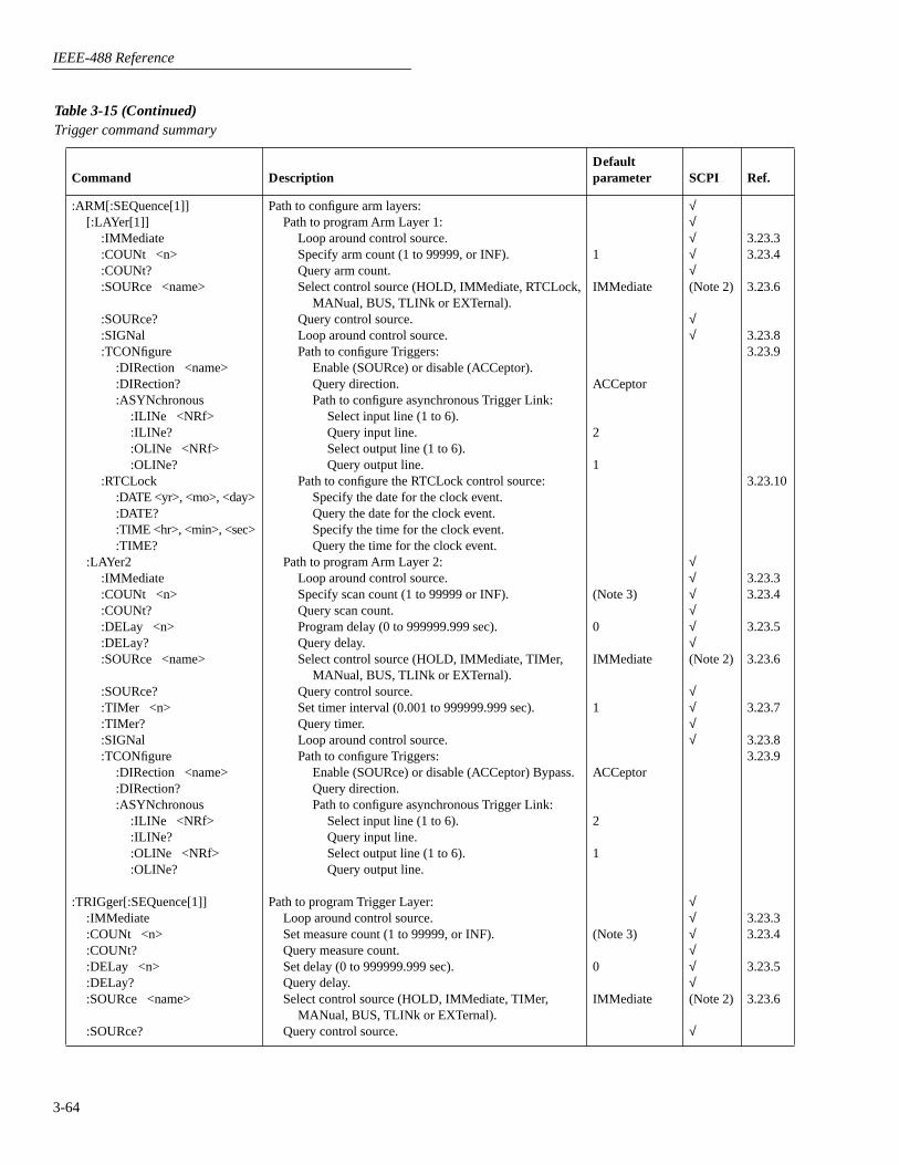
IEEE-488 Reference
3-64
:ARM[:SEQuence[1]][:LAYer[1]]
:IMMediate:COUNt <n>:COUNt?:SOURce <name>
:SOURce?:SIGNal:TCONfigure
:DIRection <name>:DIRection?:ASYNchronous
:ILINe <NRf>:ILINe?:OLINe <NRf>:OLINe?
:RTCLock:DATE <yr>, <mo>, <day>:DATE?:TIME <hr>, <min>, <sec>:TIME?
:LAYer2:IMMediate:COUNt <n>:COUNt?:DELay <n>:DELay?:SOURce <name>
:SOURce?:TIMer <n>:TIMer?:SIGNal:TCONfigure
:DIRection <name>:DIRection?:ASYNchronous
:ILINe <NRf>:ILINe?:OLINe <NRf>:OLINe?
:TRIGger[:SEQuence[1]]:IMMediate:COUNt <n>:COUNt?:DELay <n>:DELay?:SOURce <name>
:SOURce?
Path to configure arm layers:Path to program Arm Layer 1:
Loop around control source.Specify arm count (1 to 99999, or INF).Query arm count.Select control source (HOLD, IMMediate, RTCLock,
MANual, BUS, TLINk or EXTernal).Query control source.Loop around control source.Path to configure Triggers:
Enable (SOURce) or disable (ACCeptor).Query direction.Path to configure asynchronous Trigger Link:
Select input line (1 to 6).Query input line.Select output line (1 to 6).Query output line.
Path to configure the RTCLock control source:Specify the date for the clock event.Query the date for the clock event.Specify the time for the clock event.Query the time for the clock event.
Path to program Arm Layer 2:Loop around control source.Specify scan count (1 to 99999 or INF).Query scan count.Program delay (0 to 999999.999 sec).Query delay.Select control source (HOLD, IMMediate, TIMer,
MANual, BUS, TLINk or EXTernal).Query control source.Set timer interval (0.001 to 999999.999 sec).Query timer.Loop around control source.Path to configure Triggers:
Enable (SOURce) or disable (ACCeptor) Bypass.Query direction.Path to configure asynchronous Trigger Link:
Select input line (1 to 6).Query input line.Select output line (1 to 6).Query output line.
Path to program Trigger Layer:Loop around control source.Set measure count (1 to 99999, or INF).Query measure count.Set delay (0 to 999999.999 sec).Query delay.Select control source (HOLD, IMMediate, TIMer,
MANual, BUS, TLINk or EXTernal).Query control source.
1
IMMediate
ACCeptor
2
1
(Note 3)
0
IMMediate
1
ACCeptor
2
1
(Note 3)
0
IMMediate
√√√√√(Note 2)
√√
√√√√√√(Note 2)
√√√√
√√√√√√(Note 2)
√
3.23.33.23.4
3.23.6
3.23.83.23.9
3.23.10
3.23.33.23.4
3.23.5
3.23.6
3.23.7
3.23.83.23.9
3.23.33.23.4
3.23.5
3.23.6
Table 3-15 (Continued)Trigger command summary
Command DescriptionDefault parameter SCPI Ref.

IEEE-488 Reference
3-65
:TRIGger[:SEQuence[1]]:TIMer <n>:TIMer?:SIGNal:TCONfigure
:PROTocol <name>:PROTocol?:DIRection <name>:DIRection?:ASYNchronous
:ILINe <NRf>:ILINe?:OLINe <NRf>:OLINe?
:SSYNchronous:LINE <NRf>:LINE?
Set timer interval (0.001 to 999999.999 sec).Request the programmed timer interval.Loop around control source.Path to configure Triggers:
Select protocol (ASYNchronous or SSYNchronous).Query protocol.Enable (SOURce) or disable (ACCeptor) Bypass.Query direction.Path to configure asynchronous Trigger Link:
Select input line (1 to 6).Query input line.Select output line (1 to 6).Query output line.
Path to configure semi-synchronous Trigger Link:Select trigger line (1 to 6).Query trigger line.
0.1
ASYNchronous
ACCeptor
2
1
1
√√√
3.23.7
3.23.83.23.9
Notes:1. Defaults for continuous initiation:
:SYSTem:PRESet enables continuous initiation*RST disables continuous initiation
2. TLINK and RTCLock (Arm Layer 1) are non-SCPI parameters for the :SOURce command. The command (:SOURce), and all the other parameters are SCPI confirmed.
3. Defaults for count (Arm Layer 2 and Trigger Layer)::SYSTem:PRESet sets the count to INF (infinite).*RST sets the count to 1.
Table 3-15 (Continued)Trigger command summary
Command DescriptionDefault parameter SCPI Ref.

IEEE-488 Reference
3-66
Table 3-16UNIT command summary
Command DescriptionDefault parameter SCPI
:UNIT:TEMPerature <name>:TEMPerature?:VOLTage
:AC <name>:DB
:REFerence <n>:REFerence?
:DBM:IMPedance <n>:IMPedance?
:AC?
Select temperature measurement units (C, CEL, F, FAR or K).Query temperature units.Path to configure ACV units.
Select ACV measurement units (V, DB or DBM).Path to set DB reference voltage.
Specify reference in volts.Query DB reference.
Path to set DBM reference impedance.Specify reference impedance (1-9999).Query DBM reference impedance.
Query ACV units.
C
V
1
75
√√

IEEE-488 Reference
3-67
3.12
Calculate subsystems
The commands in this subsystem are used to configure and control the three Calculate sub-systems and are summarized in Table 3-4.
:CALCulate[1]
This subsystem is used to configure and control the Polynomial and Percent math calculations.Detailed information on math calculations is provided in paragraph 2.10.
:FORMat <name>
:CALCulate[1]:FORMat <name> Specify CALC 1 format
<name> = NONE No calculationPOLynomial Polynomial math calculationPERCent Percent math calculationPDEViation Percent deviation math calculation
:FORMat? Query programmed math format
This command is used to specify the format for the CALC 1 math calculation. With NONEselected, no CALC 1 calculation is performed. With one of the other formats selected andCALC 1 enabled (see :STATe), the result of the calculation is displayed. The calculated readingis refreshed every time the instrument takes a reading.
PRINT #1, "output 16; :calc:form perc; form?" ' Select percent and query format
PRINT #1, "enter 16" ' Get response message from 2002
:KMATh commands
:MA0Factor <NRf>
:CALCulate[1]:KMATh:MA0Factor <NRf> Specify “a0” factor
<NRf> = -9.999999e30 to +9.999999e30
:MA0Factor Query “a0” factor
This command is used to define the “a0” factor for the polynomial calculation.
PRINT #1, "output 16; :calc:kmat:ma0f 6; ma0f?" ' Set "a0" and query.PRINT #1, "enter 16" ' Get response from 2002
:MA1Factor <NRf>
:CALCulate[1]:KMATh:MA1Factor <NRf> Specify “a1” factor
<NRf> = -9.999999e20 to +9.999999e20
:MA1Factor Query “a1” factor
3.12.1
Parameters
Query
Description
Program fragment
Parameters
Query
Description
Program fragment
Parameters
Query

IEEE-488 Reference
3-68
This command is used to specify the “a1” factor for the polynomial calculation.
PRINT #1, "output 16; :calc:kmat:ma1f 4; ma1f?" ' Set "a1" and query.PRINT #1, "enter 16" ' Get response from 2002
:MA2Factor <NRf>
:CALCulate[1]:KMATh:MA2Factor <NRf> Specify “a2” factor
<NRf> = -9.999e20 to +9.999e20
:MA2Factor Query “a2” factor
This command is used to specify the “a2” factor for the polynomial calculation.
PRINT #1, "output 16; :calc:kmat:ma2f 6; ma0f?" ' Set "a2" and query.PRINT #1, "enter 16" ' Get response from 2002
:PERCent <NRf>
:CALCulate[1]:KMATh:PERCent <NRf> Specify Percent target value
<NRf> = -9.999999e35 to +9.999999e35 Specify target value for Percent calculation.
:PERCent? Query Percent target value
This command is used to specify the target value for the Percent calculation.
PRINT #1, "output 16; :calc:kmat:perc 10; perc?" ' Set target to 10% and query
PRINT #1, "enter 16" ' Get response message from 2002
:STATe <b>
:CALCulate[1]:STATe <b> Control CALC 1
<b> = 0 or OFF Disable CALC 1 calculation1 or ON Enable CALC 1 calculation
:STATe? Query state (on or off) of CALC 1
This command is used to enable or disable the CALC 1 calculation. When enabled, each instru-ment reading will reflect the selected calculation (see :FORMat).
PRINT #1, "output 16; :calc:stat on;stat?" ' Enable CALC1 and queryPRINT #1, "enter 16" ' Get response message from 2002
:DATA commands[:LATest]?
:CALCulate[1]:DATA[:LATest]? Read CALC 1 result
This query command is used to read the result of the CALC 1 calculation. If CALC 1 is disabledor NONE is selected, the “raw” reading will instead be read.
Description
Program fragment
Parameters
Query
Description
Program fragment
Parameters
Query
Description
Program fragment
Parameters
Query
Description
Program fragment
Description
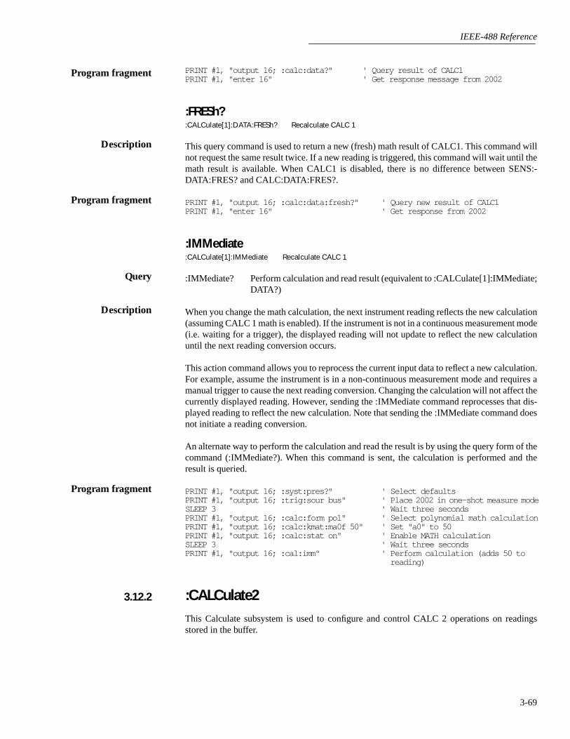
IEEE-488 Reference
3-69
PRINT #1, "output 16; :calc:data?" ' Query result of CALC1PRINT #1, "enter 16" ' Get response message from 2002
:FRESh?
:CALCulate[1]:DATA:FRESh? Recalculate CALC 1
This query command is used to return a new (fresh) math result of CALC1. This command willnot request the same result twice. If a new reading is triggered, this command will wait until themath result is available. When CALC1 is disabled, there is no difference between SENS:-DATA:FRES? and CALC:DATA:FRES?.
PRINT #1, "output 16; :calc:data:fresh?" ' Query new result of CALC1PRINT #1, "enter 16" ' Get response from 2002
:IMMediate
:CALCulate[1]:IMMediate Recalculate CALC 1
:IMMediate? Perform calculation and read result (equivalent to :CALCulate[1]:IMMediate;DATA?)
When you change the math calculation, the next instrument reading reflects the new calculation(assuming CALC 1 math is enabled). If the instrument is not in a continuous measurement mode(i.e. waiting for a trigger), the displayed reading will not update to reflect the new calculationuntil the next reading conversion occurs.
This action command allows you to reprocess the current input data to reflect a new calculation.For example, assume the instrument is in a non-continuous measurement mode and requires amanual trigger to cause the next reading conversion. Changing the calculation will not affect thecurrently displayed reading. However, sending the :IMMediate command reprocesses that dis-played reading to reflect the new calculation. Note that sending the :IMMediate command doesnot initiate a reading conversion.
An alternate way to perform the calculation and read the result is by using the query form of thecommand (:IMMediate?). When this command is sent, the calculation is performed and theresult is queried.
PRINT #1, "output 16; :syst:pres?" ' Select defaultsPRINT #1, "output 16; :trig:sour bus" ' Place 2002 in one-shot measure modeSLEEP 3 ' Wait three secondsPRINT #1, "output 16; :calc:form pol" ' Select polynomial math calculationPRINT #1, "output 16; :calc:kmat:ma0f 50" ' Set "a0" to 50PRINT #1, "output 16; :calc:stat on" ' Enable MATH calculationSLEEP 3 ' Wait three secondsPRINT #1, "output 16; :cal:imm" ' Perform calculation (adds 50 to
reading)
:CALCulate2
This Calculate subsystem is used to configure and control CALC 2 operations on readingsstored in the buffer.
Program fragment
Description
Program fragment
Query
Description
Program fragment
3.12.2

IEEE-488 Reference
3-70
:FORMat <name>
:CALCulate2:FORMat <name> Specify CALC 2 format
<name> = MEAN Mean value of readings in bufferSDEV Standard deviation of readings in bufferMAX Largest reading in bufferMIN Lowest reading in bufferPKPK Peak-to-peak value of readings in bufferNONE No calculation
:FORMat? Query programmed math format
This command is used to specify the format for the CALC 2 math calculation. The calculationoperations for CALC 2 use data stored in the buffer.
With NONE selected, no CALC 2 calculation will be performed. With one of the other formatsselected and CALC 2 enabled (see :STATe), the calculation is performed every time the :IMMe-diate or :IMMediate? command is executed.
Details on MEAN, SDEV, MAX and MIN are provided in paragraph 2.8.4.
PKPK = MAX - MIN
where: MAX is the largest reading in the bufferMIN is the lowest reading in the buffer
PRINT #1, "output 16; :calc2:form max; form?" ' Select MAX format and queryPRINT #1, "enter 16" ' Get response message from 2002
:STATe <b>
:CALCulate2:STATe <b> Control CALC 2
<b> = 0 or OFF Disable CALC 2 calculation1 or ON Enable CALC 2 calculation
:STATe? Query state (on or off) of CALC 2
This command is used to enable or disable the CALC 2 calculation. When enabled, the selectedCALC 2 format will be calculated when the :IMMediate or :IMMediate? command is executed.
PRINT #1, "output 16; :calc2:stat on; stat?" ' Enable CALC 2 and queryPRINT #1, "enter 16" ' Get response message from 2002
:IMMediate
:CALCulate2:IMMediate Perform CALC 2
:IMMediate? Perform calculation and read result (equivalent to :CALCulate2:IMMediate;DATA?)
The :IMMediate command is used to perform the selected CALC 2 operation on the readings inthe buffer (assuming CALC 2 is enabled; see :STATe). After performing the calculation, the re-sult can be read by using the :CALCulate2:DATA? query command.
Parameters
Query
Description
Program fragment
Parameters
Query
Description
Program fragment
Query
Description

IEEE-488 Reference
3-71
An alternate way to perform the calculation and read the result is by using the query form of thecommand (:IMMediate?). When this command is sent, the calculation is performed and theresult is queried.
This example assumes that there are readings stored in the buffer and CALC 2 is enabled:
PRINT #1, "output 16; :calc2:form max" ' Select MAX formatPRINT #1, "output 16; :calc2:imm?" ' Perform math and query resultPRINT #1, "enter 16" ' Get response message from 2002
:DATA?
:CALCulate2:DATA? Read CALC 2 result
This query command is used to read the result of the CALC 2 operation. If CALC 2 is disabledor NONE is selected, the “raw” reading will instead be read.
Note that this command does not initiate a calculation. This command is used to simply read theresult of the last calculation.
PRINT #1, "output 16; :calc2:data?" ' Query CALC2 readingPRINT #1, "enter 16" ' Get response message from 2002
:CALCulate3
This Calculate subsystem is used to configure and control the limit tests (LIMIT 1 test and LIM-IT 2 test). See paragraph 2.12.5 for details on limit tests.
[:DATA] <n>
:CALCulate3:LIMit[1]:UPPer[:DATA] <n> Specify upper LIMIT 1:CALCulate3:LIMit[1]:LOWer[:DATA] <n> Specify lower LIMIT 1:CALCulate3:LIMit2:UPPer[:DATA] <n> Specify upper LIMIT 2:CALCulate3:LIMit2:LOWer[:DATA] <n> Specify lower LIMIT 2
<n> = -9.999999e35 to +9.999999e35 Specify limit valueDEFault Set specified upper limit to 1
Set specified lower limit to -1MINimum Set specified limit to -9.999999e35MAXimum Set specified limit to +9.999999e35
:UPPer? Query specified upper limit:UPPer? DEFault Query *RST default upper limit:UPPer? MINimum Query lowest allowable upper limit:UPPer? MAXimum Query largest allowable upper limit
:LOWer? Query specified lower limit:LOWer? DEFault Query *RST default lower limit:LOWer? MINimum Query lowest allowable lower limit:LOWer? MAXimum Query largest allowable lower limit
These commands are used to set the upper and lower limits for LIMIT 1 and LIMIT 2. Theactual limit depends on which measurement function is currently selected. For example, a limitvalue of 1 is 1V for the volts functions (DCV or ACV), 1A for the current functions (DCI or
Program fragment
Description
Program fragment
3.12.3
Parameters
Query
Description

IEEE-488 Reference
3-72
ACI), 1
Ω
on the ohms functions (
Ω
2 or
Ω
4), and 1° (C, F or K) for the temperature function(TEMP). A limit value is not range sensitive. A limit of 2 for DCV is 2V on all measurementranges. Note that limit tests cannot be performed on frequency (FREQ) measurements.
PRINT #1, "output 16; :calc3:lim:upp 10; upp?" ' Set upper LIMIT 1 and queryPRINT #1, "enter 16" ' Get response message from
2002
:SOURce <NRf>
:CALCulate3:LIMit[1]:UPPer:SOURce <NRf> Specify pattern; upper LIMIT 1 failure:CALCulate3:LIMit[1]:LOWer:SOURce <NRf> Specify pattern; lower LIMIT 1 failure:CALCulate3:LIMit2:UPPer:SOURce <NRf> Specify pattern; upper LIMIT 2 failure:CALCulate3:LIMit2:LOWer:SOURce <NRf> Specify pattern; lower LIMIT 2 failure
<NRf> = 0 to 15 Specify digital pattern for output port
:SOURce? Query source value for specified limit
These commands are used to specify which line(s) of the Digital Output Port will go true whena limit test failure occurs. The first failure in the test sequence determines the digital output pat-tern. Subsequent failures in the test sequence will not change the digital output pattern on theoutput port.
Each output line is assigned a decimal weight as follows:
Digital Output Decimal Weight
Line #1 1Line #2 2Line #3 4Line #4 8
The parameter value for the digital pattern is determined by adding the decimal weights of thedesired output lines. For example, if you want output lines #2 and #3 to go true when the upperlimit of LIMIT 1 is the first failure in the test sequence, use a parameter value of 6 (2+4).
The actual true state (high or low) of each Digital Output line depends on its programmed po-larity. Polarity is programmed from the OUTPut subsystem (see paragraph 3.16).
Note that when the binning strobe is enabled (see :BSTRobe command path), output line #4 isnot considered to be part of the digital output pattern. The binning strobe uses line #4. With thebinning strobe enabled, parameters 8 through 15 are treated the same as parameters 0 through 7.
PRINT #1, "output 16; :calc3:lim:upp:sour 4; sour?" ' Select line #4 and queryPRINT #1, "enter 16" ' Get response message
from 2002
:STATe <b>
:CALCulate3:LIMit[1]:STATe <b> Control LIMIT 1 test:CALCulate3:LIMit2:STATe <b> Control LIMIT 2 test
<b> = 1 or ON Enable specified limit test0 or OFF Disable specified limit test
:STATe? Query state of specified limit test
Program fragment
Parameters
Query
Description
Program fragment
Parameters
Query

IEEE-488 Reference
3-73
These commands are used to enable or disable LIMIT 1 and LIMIT 2 tests. When enabled, thetest sequence for limits will be performed every time the instrument performs a measurement.Testing is performed in the following sequence: Low Limit 1, High Limit 1, Low Limit 2 andHigh Limit 2. Any limit test (LIMIT 1 or LIMIT 2) not enabled is simply not performed.
Note that when a limit test (LIMIT 1 or LIMIT 2) is enabled, the digital output port cannot becontrolled from the Source Subsystem.
A fail indication (see :FAIL?) for LIMIT 1 or LIMIT 2 is cleared when the respective limit testis disabled.
PRINT #1, "output 16; :calc3:lim:stat on; stat?" ' Enable LIMIT 1 test and query
PRINT #1, "enter 16" ' Get response message from 2002
:FAIL?
:CALCulate3:LIMit[1]:FAIL? Read LIMIT 1 test results:CALCulate3:LIMit2:FAIL? Read LIMIT 2 test results
These commands are used to read the results of LIMIT 1 and LIMIT 2 tests:
0 = Limit test passed1 = Limit test failed
The response message (0 or 1) only tells you if a limit test has passed or failed. It does not tellyou which limit (upper or lower) has failed. To determine which limit has failed, you will haveto read the Measurement Event Register (see paragraph 3.20.1).
Reading the results of a limit test does not clear the fail indication of the test. A failure can becleared by using a :CLEar command, or by disabling the test (:STATe OFF).
PRINT #1, "output 16; :calc3:lim:fail?" ' Query result of LIMIT 1 testPRINT #1, "enter 16" ' Get response message from 2002
:CLEar commands
[:IMMediate]
:CALCulate3:LIMit[1]:CLEar[:IMMediate] Clear LIMIT 1 test failure:CALCulate3:LIMit2:CLEar[:IMMediate] Clear LIMIT 2 test failure
These action commands are used to clear the fail indication of LIMIT 1 and LIMIT 2 tests. Notethat a failure is also cleared when the limit test is disabled (:STATe OFF).
PRINT #1, "output 16; :calc3:lim:cle" ! Clear fail condition of LIMIT 1 test.
:AUTO <b>
:CALCulate3:LIMit[1]:CLEar:AUTO <b> Control auto-clear; LIMIT 1:CALCulate3:LIMit2:CLEar:AUTO <b> Control auto-clear; LIMIT 2
<b> = 1 or ON Enable auto-clear for limit failure0 or OFF Disable auto-clear for limit failure
:AUTO? Query state of auto clear
Description
Program fragment
Description
Program fragment
Description
Program fragment
Parameters
Query

IEEE-488 Reference
3-74
With auto-clear enabled, the fail indication of a limit test clears when instrument operation en-ters the idle state. With auto-clear disabled, the fail indication will remain until it is cleared bythe :CLEar[:IMMediate] command.
PRINT #1, "output 16; :calc3:lim:cle:auto on; auto?" ' Enable auto-clear and query
PRINT #1, "enter 16" ' Get response message from 2002
:PASS:SOURce <NRf>
:CALCulate3:PASS:SOURce <NRf> Specify “pass” pattern
<NRf> = 0 to 15 Specify digital pattern for output port
:SOURce Query programmed source value
This command is used to specify which line(s) of the Digital Output Port will go true when thereare no failures in the limit tests.
Each output line is assigned a decimal weight as follows:
Digital Output Decimal Weight
Line #1 1Line #2 2Line #3 4Line #4 8
The parameter value for the digital pattern is determined by adding the decimal weights of thedesired output lines. For example, if you want output lines #2 and #3 to go true when all enabledlimit tests pass, use a parameter value of 6 (2+4).
The actual true state (high or low) of each digital output line depends on its programmed polar-ity. Polarity is programmed from the OUTPut Subsystem (see paragraph 3.16).
Note that when the binning strobe is enabled (see :BSTRobe command path), output line #4 isnot considered to be part of the digital output pattern. The binning strobe uses line #4. With thestrobe enabled, parameter values 8 through 15 are treated the same as parameters 0 through 7.
PRINT #1, "output 16; :calc3:pass:sour 3; sour?" ' Select line #3PRINT #1, "enter 16" ' Get response message from
2002
:CLIMits:FAIL?
:CALCulate3:CLIMits:FAIL? Read composite result of limit tests
This query command is used to obtain the composite result of the LIMIT 1 and LIMIT 2 tests.The composite result is the logical OR’ed summary of LIMIT 1 and LIMIT 2:
1 = One or both tests have failed.0 = Both tests have passed.
In the event of a failure (1), you can determine which test(s) has failed by using the fail com-mand of each limit (:LIMit1:FAIL? and :LIMit2:FAIL?).
Description
Program fragment
Parameters
Query
Description
Program fragment
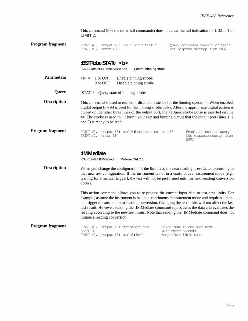
IEEE-488 Reference
3-75
This command (like the other fail commands) does not clear the fail indication for LIMIT 1 orLIMIT 2.
PRINT #1, "output 16; :calc3:clim:fail?" ' Query composite results of testsPRINT #1, "enter 16" ' Get response message from 2002
:BSTRobe:STATe <b>:CALCulate3:BSTRobe:STATe <b> Control binning strobe
<b> = 1 or ON Enable binning strobe0 or OFF Disable binning strobe
:STATe? Query state of binning strobe
This command is used to enable or disable the strobe for the binning operation. When enabled,digital output line #4 is used for the binning strobe pulse. After the appropriate digital pattern isplaced on the other three lines of the output port, the >10µsec strobe pulse is asserted on line#4. The strobe is used to “inform” your external binning circuit that the output port (lines 1, 2and 3) is ready to be read.
PRINT #1, "output 16; :calc3:bstr:stat on; stat?" ' Enable strobe and queryPRINT #1, "enter 16" ' Get response message from
2002
:IMMediate:CALCulate3:IMMediate Perform CALC 3
When you change the configuration of the limit test, the next reading is evaluated according tothat new test configuration. If the instrument is not in a continuous measurement mode (e.g.,waiting for a manual trigger), the test will not be performed until the next reading conversionoccurs.
This action command allows you to re-process the current input data to test new limits. Forexample, assume the instrument is in a non-continuous measurement mode and requires a man-ual trigger to cause the next reading conversion. Changing the test limits will not affect the lasttest result. However, sending the :IMMediate command reprocesses the data and evaluates thereading according to the new test limits. Note that sending the :IMMediate command does notinitiate a reading conversion.
PRINT #1, "output 16; :trig:sour bus" ' Place 2002 in one-shot modeSLEEP 3 ' Wait three secondsPRINT #1, "output 16; :calc3:imm" ' Re-perform limit test
Program fragment
Parameters
Query
Description
Program fragment
Description
Program fragment

IEEE-488 Reference
3-76
3.13 :DISPlay subsystem
The display subsystem controls the display of the Model 2002 and is summarized in Table 3-5.
:TEXT commands
:DATA <a>:DISPlay[:WINDow[1]]:TEXT:DATA <a> Define message for top display:DISPlay:WINDow2:TEXT:DATA <a> Define message for bottom display
<a> = ASCII characters for message
Types: String ‘aa...a’ or “aa...a”Indefinite Block #0aa...aDefinite Block #XYaa...a
where; Y = number of characters in message:Up to 20 for top displayUp to 32 for bottom display
X = number of digits that make up Y (1 or 2)
:DATA? Query the defined text message
These commands define text messages for display. A message can be as long as 20 charactersfor the top display, and up to 32 characters for the bottom display. A space is counted as a char-acter. Excess message characters results in an error.
An indefinite block message must be the only command in the program message or the last com-mand in the program message. If you include a command after an indefinite block message (onthe same line), it will be treated as part of the message and is displayed instead of executed.
PRINT #1, "output 16; :disp:text:data ' Model 2002';data?" ' Define and query message
PRINT #1, "enter 16" ' Get response mes-sage from 2002
:STATe <b>:DISPlay[:WINDow[1]]:TEXT:STATe <b> Control (on/off) message; top display:DISPlay:WINDow2:TEXT:STATe <b> Control (on/off) message; bottom display
<b> = 0 or OFF Disable text message for specified display= 1 or ON Enable text message for specified display
:STATe? Query state of message mode for specified display
These commands enable and disable the text message modes. When enabled, a defined messageis displayed. When disabled, the message is removed from the display.
A user defined text message remains displayed only as long as the instrument is in remote. Tak-ing the instrument out of remote (by pressing the LOCAL key or sending LOCAL 16), cancelsthe message and disables the text message mode.
Parameters
Query
Description
Program fragment
Parameters
Query
Description

IEEE-488 Reference
3-77
PRINT #1, "output 16; :disp:text:stat on; stat?" ' Enable and query message mode
PRINT #1, "enter 16" ' Get response message from 2002
:DATA?:DISPlay[:WINDow[1]]:DATA? Read top display:DISPlay:WINDow2:DATA? Read bottom display
These query commands are used to read what is currently being displayed on the top and bottomdisplays. After sending one of these commands and addressing the Model 2002 to talk, the dis-played data (message or reading) will be sent to the computer.
PRINT #1, "output 16; :disp:data?" ' Query displayed dataPRINT #1, "enter 16" ' Get response message from 2002
:CNDisplay:DISPlay:CNDisplay Clear (cancel) NEXT display
This action command is used to clear the bottom display of NEXT (or PREV) messages andcancel the operations associated with them. This command has no effect on any other messagetypes.
This example assumes that a NEXT operation is currently being displayed.
PRINT #1, "output 16; :cnd" ' Clear NEXT display
:SMESsage <b>:DISPlay:SMESsage <b> Control status message
<b> = 0 or OFF Disable status messages= 1 or ON Enable status messages
:SMESsage? Query state of status message mode
This command is used to enable/disable the status message mode. The status message mode isa diagnostic tool that provides real-time messages that relate to the current operating state of theinstrument. Table 2-4 lists the status messages.
PRINT #1, "output 16; :disp:smes on; smes?" ' Enable and query status message mode
PRINT #1, "enter 16" ' Get response message from 2002
:ENABle <b>:DISPlay:ENABle <b> Control display circuitry
<b> = 0 or OFF Disable display circuitry= 1 or ON Enable display circuitry
:ENABle? Query state of display
Program fragment
Description
Program fragment
Description
Program fragment
Parameters
Query
Description
Program fragment
Parameters
Query

IEEE-488 Reference
3-78
This command is used to enable and disable the front panel display circuitry. When disabled,the instrument operates at a higher speed. While disabled, the display is frozen with the follow-ing message:
FRONT PANEL DISABLEDPress LOCAL to resume.
As reported by the message, all front panel controls (except LOCAL) are disabled. Normal dis-play operation can be resumed by using the :ENABle command to enable the display or by put-ting the Model 2002 into local.
PRINT #1, "output 16; :disp:enab off; enab?" ' Disable and query displaycircuitry
PRINT #1, "enter 16" ' Get response message from 2002
Description
Program fragment

IEEE-488 Reference
3-79
3.14 :FORMat subsystem
The commands for this subsystem are used to select the data format for transferring instrumentreadings over the bus. The BORDer command and DATA command affect readings transferredfrom the buffer ONLY. (i.e. SENSE: DATA? or CALC:DATA? is always be sent in ASCII.)These commands are summarized in Table 3-6.
[:DATA] <type>[,length]:FORMat[:DATA] <type>[,<length>] Specify data format
<type>[,<length>] = ASCii ASCII formatREAL,32 IEEE754 single precision formatREAL,64 IEEE754 double precision formatSREal IEEE754 single precision formatDREal IEEE754 double precision format
NOTES:
1. When using the ASCii, SREal or DREal parameter, a <length> parameter is not required.
2. If you do not use a <length> parameter with the REAL parameter, the <length> defaults to32 (single precision format).
[:DATA]? Query data format
This command is used to select the data format for transferring readings over the bus. For everyreading conversion, the data string sent over the bus contains the elements specified by the:ELEMents command. The specified elements are sent in a particular order.
The ASCII data format is in a direct readable form for the operator. Most BASIC languages eas-ily convert ASCII mantissa and exponent to other formats. However, some speed is compro-mised to accommodate the conversion. Figure 3-18 shows the ASCII format that includes all thedata elements.
Parameters
Query
Description
Figure 3-18ASCII data format
Reading Time Stamp *ReadingNumber
ChannelNumber
±1.2345678E±00NVDC,13:45:23.65 03-SEP-1993, ±123456RDNG#, 01intchan
Mantissa Exponent Units(readingnumber)Units:
VDC = DC VoltsVAC = AC VoltsADC = DC CurrentAAC = AC CurrentOHM = 2-wire ResistanceOHM4W = 4-wire ResistanceHZ = Frequency
Status:N = NormalO = OverflowR = Reference (Rel)
C = Temperature in °CF = Temperature in °FK = Temperature in K
00 = No channel01 to 80 = Channel Number
Units:intchan = Internal channelextchan = External channel
Time Date
* Real time clock timestamp shown

IEEE-488 Reference
3-80
REAL,32 or SREal will select the binary IEEE754 single precision data format. Figure 3-19shows the normal byte order format for each data element. For example, if three valid elementsare specified, the data string for each reading conversion is made up of three 32-bit data blocks.Note that the data string for each reading conversion is preceded by a 2-byte header that is thebinary equivalent of an ASCII # sign and 0.
REAL,64 or DREal selects the binary IEEE754 double precision data format and is shown inFigure 3-20 (normal byte order shown). This format is similar to the single precision formatexcept that it is 64 bits long.
Figure 3-19IEEE754 single precision data format (32 data bits)
Byte 1
7 0
Header
# 0
Byte 2
7 0
Byte 3
7 0
Byte 4
7 0
s e f
s = sign bit (0 = positive, 1 = negative)e = exponent bits (8)f = fraction bits (23)
Normal byte order shown. For swapped byte order,bytes sent in reverse order: Header, Byte 4, Byte 3,Byte 2, Byte 1.
The Header is only sent once for each measurement conversion.

IEEE-488 Reference
3-81
PRINT #1, "output 16; :form sre; form?" ' Select SREal format and queryPRINT #1, "enter 16" ' Get response message from 2002
:ELEMents <item list>:FORMat:ELEMents <item list> Specify data elements for data string
<item list>: READing Includes reading in data stringCHANnel Includes channel numberRNUMber Includes reading numberUNITs Includes unitsTIMEstamp Includes time stampSTATus Includes status of reading
NOTE: Each item in the list must be separated by a comma (,).
:ELEMents? Query elements in data string
This command is used to specify the elements to be included in the data string for each mea-surement conversion. You can specify from one to all six elements. Each element in the list mustbe separated by a comma (,). These elements, shown in Figure 3-18, are explained as follows:
READing: Instrument reading. The resolution of this reading tracks the display resolution of theinstrument. An overflow reading reads as +9.9E37.
CHANnel: Corresponds the instrument reading to the channel number of a switching card. Ifnot scanning, the channel number is 00.
Figure 3-20IEEE754 double precision data format (64 data bits)
Byte 1
7 0
Header Byte 2
7 0
Byte 7
7 0
Byte 8
7 0
s e f
s = sign bit (0 = positive, 1 = negative)e = exponent bits (11)f = fraction bits (52)
Normal byte order shown. For swapped byte order,bytes sent in reverse order: Header, Byte 8,Byte 7 .... Byte 1.
The Header is only sent once for each measurement conversion.
Bytes 3, 4, 5, and 6 not shown.
# 0
Program fragment
Parameters
Query
Description

IEEE-488 Reference
3-82
RNUMber: The instrument keeps track of the number of readings it has performed. This readingcounter starts at zero when the instrument is turned on or when :SYStem:RNUMber:RESet issent over the bus. When a reading is sent over the bus (i.e. :FETCh?), the RNUMber elementindicates the reading number. The instrument also keeps track of the number of readings it hasstored in the buffer. When buffer readings are sent over the bus (:TRACe:DATA?), each readingnumber is referenced to the first reading, which is #0, stored in the buffer. If using Pre-trigger tostore readings, the pre-trigger readings are assigned negative numbers.
UNITs: This element attaches the function unit to the reading, the time unit (sec) to the times-tamp, and the channel unit (internal or external) to the channel number. An internal channelrefers to an internally installed switching card (such as the Model 2001-SCAN) channel, whilean external channel refers to the channel for an external switch system. This element is not avail-able for the binary formats.
TIMEstamp: A timestamp is available to reference each reading to a point in time. There are twobasic types of timestamps; real-time timestamp and relative time timestamp. The real-timetimestamp provides the time (24-hour clock format) and date for each reading sent over the bus.The relative timestamp operates as a timer that starts at zero seconds when the instrument isturned on or when the relative timestamp is reset (:SYSTem:TSTamp:RELative:RESet). Thetimestamp for each reading sent over the bus is referenced, in seconds, to the start time. After99,999.999999 seconds, the timer resets back to zero and starts over.
Timestamp is also available for buffer readings. Timestamp can be referenced to the first readingstored in the buffer (absolute format) which is timestamped at 0 seconds, or can provide the timebetween each reading (delta format). The :TRACe:TSTamp:FORMat command is used to selectthe absolute or delta format. For the delta format, real-time timestamp is expressed as the days,hours, minutes and seconds between each reading, while the relative timestamp is expressed asseconds between each reading. When using the absolute format for the relative timestamp, anypre-trigger readings will have a negative timestamp.
STATus: This element indicates if the reading is normal (N), overflowed (O) or referenced (R)to another value. This element is not available for the binary formats.
The ASCII format shown in Figure 3-18 shows the byte order of the data string. Keep in mindthat the byte order can only be reversed for the binary formats.
When using this command to add an element, you must include all elements that you want inthe format. For example, if the reading is already specified and you want to add the time-stamp,you must include the READing parameter.
:form:elem time, read
Data elements for the item list can be listed in any order, but are always sent in the order shownin Figure 3-18.
PRINT #1, "output 16; :form:elem read, stat, unit; elem?" ' Specify elementsPRINT #1, "enter 16" ' Get response mes-
sage from 2002
:BORDer <name>:FORMat:BORDer <name> Specify binary byte order
<name> = NORMal Normal byte order for binary formatsSWAPped Reverse byte order for binary formats
Program fragment
Parameters
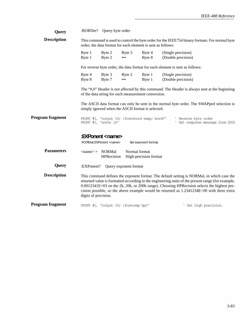
IEEE-488 Reference
3-83
:BORDer? Query byte order
This command is used to control the byte order for the IEEE754 binary formats. For normal byteorder, the data format for each element is sent as follows:
Byte 1 Byte 2 Byte 3 Byte 4 (Single precision)Byte 1 Byte 2 ••• Byte 8 (Double precision)
For reverse byte order, the data format for each element is sent as follows:
Byte 4 Byte 3 Byte 2 Byte 1 (Single precision)Byte 8 Byte 7 ••• Byte 1 (Double precision)
The “#,0” Header is not affected by this command. The Header is always sent at the beginningof the data string for each measurement conversion.
The ASCII data format can only be sent in the normal byte order. The SWAPped selection issimply ignored when the ASCII format is selected.
PRINT #1, "output 16; :form:bord swap; bord?" ' Reverse byte orderPRINT #1, "enter 16" ' Get response message from 2002
:EXPonent <name>:FORMat:EXPonent <name> Set exponent format.
<name> = NORMal Normal formatHPRecision High-precision format
:EXPonent? Query exponent format
This command defines the exponent format. The default setting is NORMal, in which case thereturned value is formatted according to the engineering units of the present range (for example,0.0012341E+03 on the 2k, 20k, or 200k range). Choosing HPRecision selects the highest pre-cision possible, so the above example would be returned as 1.2341234E+00 with three extradigits of precision.
PRINT #1, "output 16; :form:exp hpr" ' Set high precision.
Query
Description
Program fragment
Parameters
Query
Description
Program fragment

IEEE-488 Reference
3-84
3.15 :INPut subsystem
The :INPut subsystem is used for the Model 1801 Nanovolt Preamp. These commands are sum-marized in Table 3-7.
:PREamp CommandsThe :PREamp commands are used to control the Model 1801 Nanovolt Preamp card. Refer tothe Model 1801 instruction manual for detailed operating information.
:STATe <b>:INPut:PREamp:STATe <b> Enable or disable preamp
<b> = 1 or ON Enable preamp0 or OFF Disable preamp
:STATe? Query state of preamp
With the Model 1801 installed in the option slot, this command is used to enable or disablepreamp.
PRINT #1, "output 16; :inp:pre:stat on" ' Enable preampPRINT #1, "enter 16" ' Get response from 2002
:FILTer <name>:INPut:PREamp:FILTer <name> Select filter response
<name> = SLOW Select slow filter responseMED Select medium filter responseFAST Select fast filter response
:FILTer? Query selected filter response
This command is used to select the filter response for the preamp. Note that only the FASTresponse is available for the ACV and FREQ functions.
PRINT #1, "output 16; :inp:pre:filt fast" ' Select FAST filter responsePRINT #1, "enter 16" ' Get response from 2002
Parameters
Query
Description
Program fragment
Parameters
Query
Description
Program fragment

IEEE-488 Reference
3-85
3.16 :OUTPut subsystem
The OUTPut subsystem is used to set polarities for the digital output port. Commands in thissubsystem are summarized in Table 3-8.
:LSENse <name>:OUTPut:TTL[1]:LSENse <name> Set polarity of line #1:OUTPut:TTL2:LSENse <name> Set polarity of line #2:OUTPut:TTL3:LSENse <name> Set polarity of line #3:OUTPut:TTL4:LSENse <name> Set polarity of line #4
<name> = AHIGh Set polarity of specified line to active high.ALOW Set polarity of specified line to active low.
:LSENse? Query polarity of specified line
These commands are used to set the polarity of the digital output lines. When set for active high(AHIGh) polarity, the specified output line is true (ON) when the output level is high. The out-put line is false (OFF) when the output level is low. When set for active low (ALOW) polarity,the output line is true (ON) when the output level is low. The output line is false (OFF) whenthe output level is high.
The logic levels (true or false) of the digital output lines are set from the SOURce Subsystem(see paragraph 3.19).
PRINT #1, "output 16; :outp:ttl:lsen alow; lsen?" ' Set line #1 to ALOWPRINT #1, "enter 16" ' Get response message from
2002
Parameters
Query
Description
Program fragment
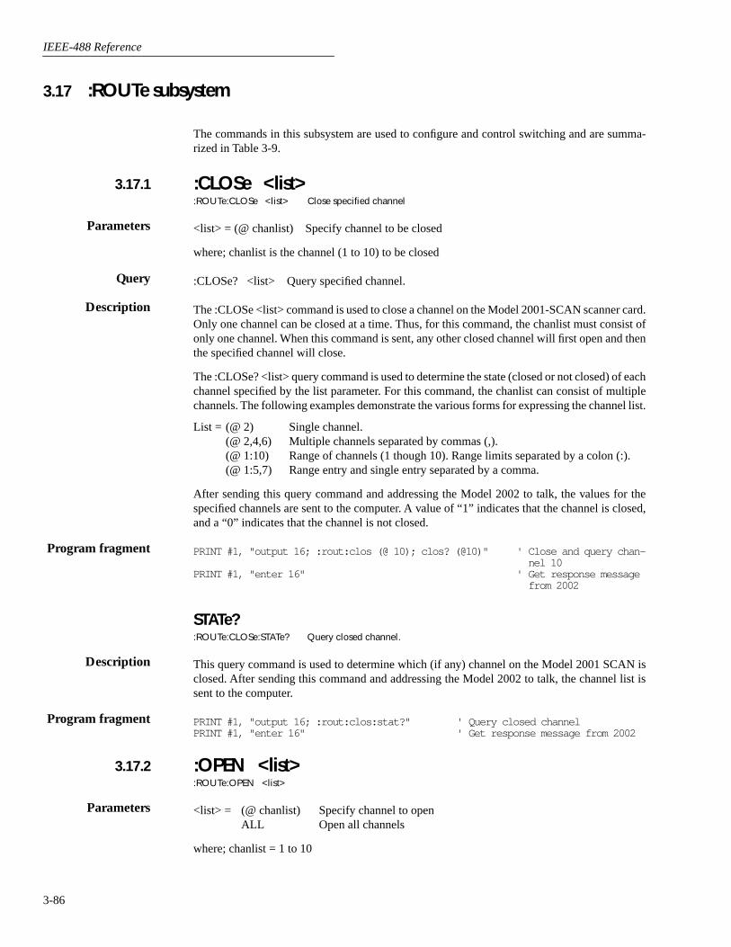
IEEE-488 Reference
3-86
3.17 :ROUTe subsystem
The commands in this subsystem are used to configure and control switching and are summa-rized in Table 3-9.
:CLOSe <list>:ROUTe:CLOSe <list> Close specified channel
<list> = (@ chanlist) Specify channel to be closed
where; chanlist is the channel (1 to 10) to be closed
:CLOSe? <list> Query specified channel.
The :CLOSe <list> command is used to close a channel on the Model 2001-SCAN scanner card.Only one channel can be closed at a time. Thus, for this command, the chanlist must consist ofonly one channel. When this command is sent, any other closed channel will first open and thenthe specified channel will close.
The :CLOSe? <list> query command is used to determine the state (closed or not closed) of eachchannel specified by the list parameter. For this command, the chanlist can consist of multiplechannels. The following examples demonstrate the various forms for expressing the channel list.
List = (@ 2) Single channel.(@ 2,4,6) Multiple channels separated by commas (,).(@ 1:10) Range of channels (1 though 10). Range limits separated by a colon (:).(@ 1:5,7) Range entry and single entry separated by a comma.
After sending this query command and addressing the Model 2002 to talk, the values for thespecified channels are sent to the computer. A value of “1” indicates that the channel is closed,and a “0” indicates that the channel is not closed.
PRINT #1, "output 16; :rout:clos (@ 10); clos? (@10)" ' Close and query chan-nel 10
PRINT #1, "enter 16" ' Get response message from 2002
STATe?:ROUTe:CLOSe:STATe? Query closed channel.
This query command is used to determine which (if any) channel on the Model 2001 SCAN isclosed. After sending this command and addressing the Model 2002 to talk, the channel list issent to the computer.
PRINT #1, "output 16; :rout:clos:stat?" ' Query closed channelPRINT #1, "enter 16" ' Get response message from 2002
:OPEN <list>:ROUTe:OPEN <list>
<list> = (@ chanlist) Specify channel to openALL Open all channels
where; chanlist = 1 to 10
3.17.1
Parameters
Query
Description
Program fragment
Description
Program fragment
3.17.2
Parameters
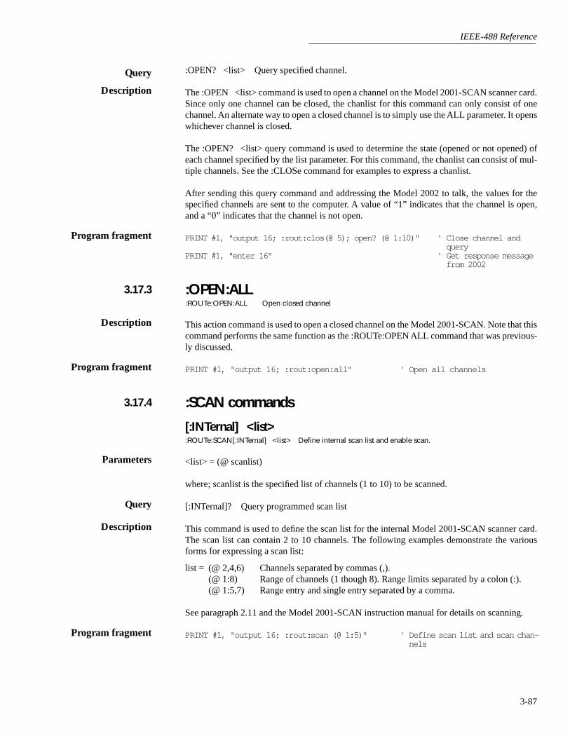
IEEE-488 Reference
3-87
:OPEN? <list> Query specified channel.
The :OPEN <list> command is used to open a channel on the Model 2001-SCAN scanner card.Since only one channel can be closed, the chanlist for this command can only consist of onechannel. An alternate way to open a closed channel is to simply use the ALL parameter. It openswhichever channel is closed.
The :OPEN? <list> query command is used to determine the state (opened or not opened) ofeach channel specified by the list parameter. For this command, the chanlist can consist of mul-tiple channels. See the :CLOSe command for examples to express a chanlist.
After sending this query command and addressing the Model 2002 to talk, the values for thespecified channels are sent to the computer. A value of “1” indicates that the channel is open,and a “0” indicates that the channel is not open.
PRINT #1, "output 16; :rout:clos(@ 5); open? (@ 1:10)" ' Close channel and query
PRINT #1, "enter 16" ' Get response message from 2002
:OPEN:ALL:ROUTe:OPEN:ALL Open closed channel
This action command is used to open a closed channel on the Model 2001-SCAN. Note that thiscommand performs the same function as the :ROUTe:OPEN ALL command that was previous-ly discussed.
PRINT #1, "output 16; :rout:open:all" ' Open all channels
:SCAN commands
[:INTernal] <list>:ROUTe:SCAN[:INTernal] <list> Define internal scan list and enable scan.
<list> = (@ scanlist)
where; scanlist is the specified list of channels (1 to 10) to be scanned.
[:INTernal]? Query programmed scan list
This command is used to define the scan list for the internal Model 2001-SCAN scanner card.The scan list can contain 2 to 10 channels. The following examples demonstrate the variousforms for expressing a scan list:
list = (@ 2,4,6) Channels separated by commas (,).(@ 1:8) Range of channels (1 though 8). Range limits separated by a colon (:).(@ 1:5,7) Range entry and single entry separated by a comma.
See paragraph 2.11 and the Model 2001-SCAN instruction manual for details on scanning.
PRINT #1, "output 16; :rout: scan (@ 1:5)" ' Define scan list and scan chan-nels
Query
Description
Program fragment
3.17.3
Description
Program fragment
3.17.4
Parameters
Query
Description
Program fragment

IEEE-488 Reference
3-88
:EXTernal <list>:ROUTe:SCAN:EXTernal <list> Define external scan list
<list> = (@ scanlist)
where; scanlist is the specified list of external channels (1 to 80) to be scanned.
:EXTernal? Query programmed scan list
The Model 2002 can operate with an external switch system, such as the Keithley Model 7001or 7002. The Model 2002 can measure up to 80 channels that are switched by the externalswitching system. This command is used to define the external scan list for the Model 2002. Seeparagraph 2.11 for details on scanning.
The scan list can contain 2 to 80 channels. See :SCAN[:INTernal] for examples to express a scanlist. The external scan by the Model 2002 is enabled by the ROUTe:SCAN:LSELect EXTernalcommand.
PRINT #1, "output 16; :rout: scan:ext (@ 1:40)" ' Define external scan list
:FUNCtion <list>, <name>:ROUTe:SCAN[:INTernal]:FUNCtion <list>, <name> Assign functions to channels; Internal:ROUTe:SCAN:EXTernal:FUNCtion <list>, <name> Assign functions to channels; External
<list> = (@ chanlist)
where; chanlist is the specified list of channels:
1 to 10 for Internal1 to 80 for External
<name> = ‘NONE’‘VOLTage:DC’‘VOLTage:AC’‘TEMPerature’‘FREQuency’‘RESistance’‘FRESistance’‘RJUNctionX’ where; X = 1 to 5‘ALTernate[1]’‘CURRent:DC’ (External only)‘CURRent:AC’ (External only)
:FUNCtion? <list> Query functions for specified channels
These commands are used to assign measurement functions for internal channels (e.g. Model2001 SCAN) or external channels. You can assign a unique measurement function to each chan-nel. The function parameter specifies the measurement function for the channels specified bythe channel list (chanlist). See :CLOSe for examples to express a chanlist.
Parameters
Query
Description
Program fragment
Parameters
Query
Description
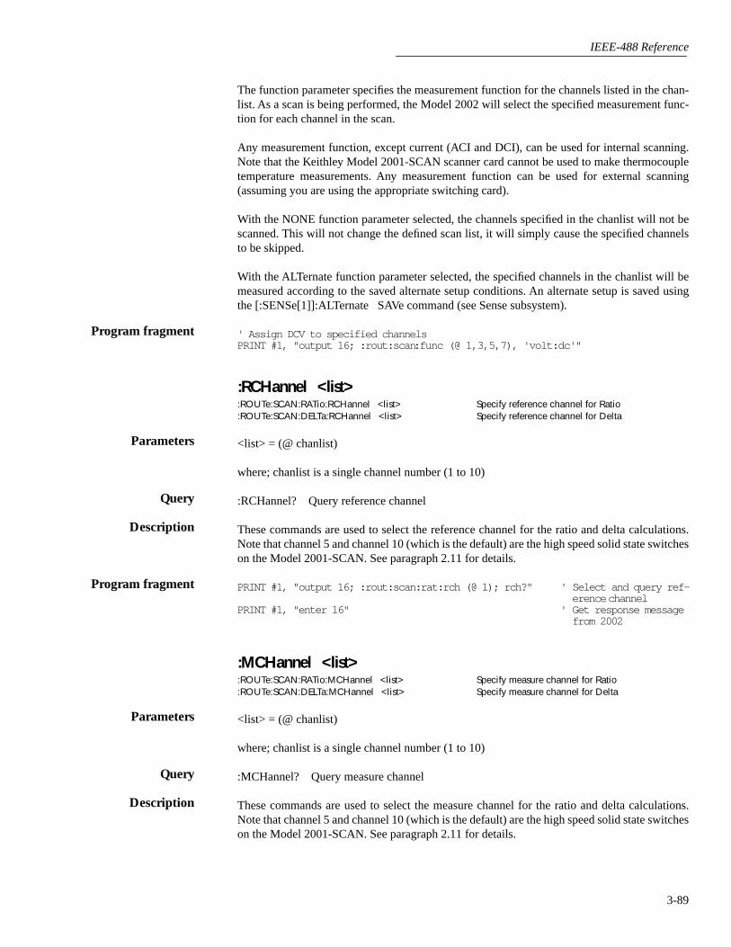
IEEE-488 Reference
3-89
The function parameter specifies the measurement function for the channels listed in the chan-list. As a scan is being performed, the Model 2002 will select the specified measurement func-tion for each channel in the scan.
Any measurement function, except current (ACI and DCI), can be used for internal scanning.Note that the Keithley Model 2001-SCAN scanner card cannot be used to make thermocoupletemperature measurements. Any measurement function can be used for external scanning(assuming you are using the appropriate switching card).
With the NONE function parameter selected, the channels specified in the chanlist will not bescanned. This will not change the defined scan list, it will simply cause the specified channelsto be skipped.
With the ALTernate function parameter selected, the specified channels in the chanlist will bemeasured according to the saved alternate setup conditions. An alternate setup is saved usingthe [:SENSe[1]]:ALTernate SAVe command (see Sense subsystem).
' Assign DCV to specified channelsPRINT #1, "output 16; :rout:scan :func (@ 1,3,5,7), 'volt:dc'"
:RCHannel <list>:ROUTe:SCAN:RATio:RCHannel <list> Specify reference channel for Ratio:ROUTe:SCAN:DELTa:RCHannel <list> Specify reference channel for Delta
<list> = (@ chanlist)
where; chanlist is a single channel number (1 to 10)
:RCHannel? Query reference channel
These commands are used to select the reference channel for the ratio and delta calculations.Note that channel 5 and channel 10 (which is the default) are the high speed solid state switcheson the Model 2001-SCAN. See paragraph 2.11 for details.
PRINT #1, "output 16; :rout:scan:rat:rch (@ 1); rch?" ' Select and query ref-erence channel
PRINT #1, "enter 16" ' Get response message from 2002
:MCHannel <list>:ROUTe:SCAN:RATio:MCHannel <list> Specify measure channel for Ratio:ROUTe:SCAN:DELTa:MCHannel <list> Specify measure channel for Delta
<list> = (@ chanlist)
where; chanlist is a single channel number (1 to 10)
:MCHannel? Query measure channel
These commands are used to select the measure channel for the ratio and delta calculations.Note that channel 5 and channel 10 (which is the default) are the high speed solid state switcheson the Model 2001-SCAN. See paragraph 2.11 for details.
Program fragment
Parameters
Query
Description
Program fragment
Parameters
Query
Description
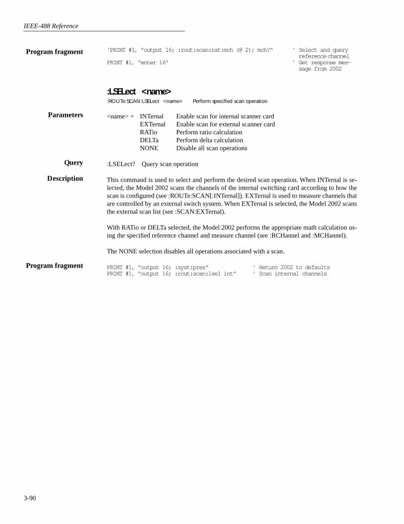
IEEE-488 Reference
3-90
'PRINT #1, "output 16; :rout:scan:rat:mch (@ 2); mch?" ' Select and query reference channel
PRINT #1, "enter 16" ' Get response mes-sage from 2002
:LSELect <name>:ROUTe:SCAN:LSELect <name> Perform specified scan operation
<name> = INTernal Enable scan for internal scanner cardEXTernal Enable scan for external scanner cardRATio Perform ratio calculationDELTa Perform delta calculationNONE Disable all scan operations
:LSELect? Query scan operation
This command is used to select and perform the desired scan operation. When INTernal is se-lected, the Model 2002 scans the channels of the internal switching card according to how thescan is configured (see :ROUTe:SCAN[:INTernal]). EXTernal is used to measure channels thatare controlled by an external switch system. When EXTernal is selected, the Model 2002 scansthe external scan list (see :SCAN:EXTernal).
With RATio or DELTa selected, the Model 2002 performs the appropriate math calculation us-ing the specified reference channel and measure channel (see :RCHannel and :MCHannel).
The NONE selection disables all operations associated with a scan.
PRINT #1, "output 16; :syst:pres" ' Return 2002 to defaultsPRINT #1, "output 16; :rout:scan:lse1 int" ' Scan internal channels
Program fragment
Parameters
Query
Description
Program fragment

IEEE-488 Reference
3-91
3.18 Sense subsystems
The Sense subsystems are used to configure and control the measurement functions (Sense 1)and to read the digital input port (Sense 2). The commands for the Sense subsystems are sum-marized in Table 3-10.
[:SENSe[1]] subsystem
This Sense 1 Subsystem is used to configure and control the measurement functions of theModel 2002. Keep in mind that a function does not have to be selected in order to program itsvarious configurations. When the function is later selected, it assumes the programmed states.
:ALTernate[1] commands
:SAVE[:SENSe[1]]:ALTernate[1]:SAVE Save Alternate setup.
This command is used to save the current instrument setup as the Alternate setup. The instru-ment can be returned to the Alternate setup by using the :ALTernate[1]:RECall command.
An Alternate setup can be used as the function parameter for a scan (see :ROUTe :SCAN).
PRINT #1, "output 16; :alt:save" ' Save present setup as alternate setup
:RECall[:SENSe[1]]:ALTernate[1]:RECall Return to Alternate setup.
This command is used to return the instrument to an Alternate setup (see :ALTernate[1]:SAVE).If there is no Alternate setup currently saved, this command is a No-Op (no operation).
PRINT #1, "output 16; :alt:rec" ' Recall alternate setup
:FUNCtion <name>[:SENSe[1]]:FUNCtion <name> Select measurement function.
<name> = ‘VOLTage:AC’ Select ACV‘VOLTage:DC’ Select DCV‘RESistance’ Select Ω2‘FRESistance’ Select Ω4‘CURRent:AC’ Select ACI‘CURRent:DC’ Select DCI‘FREQuency’ Select FREQ‘TEMPerature’ Select TEMP
:FUNCtion? Query currently programmed function.
3.18.1
3.18.2
Description
Program fragment
Description
Program fragment
3.18.3
Parameters
Query

IEEE-488 Reference
3-92
The :FUNCtion command is used to select the measurement function of the instrument. Notethat parameter names are enclosed in single quotes (‘). However, double quotes (“) can insteadbe used. For example:
:func ‘volt:dc’ = :func “volt:dc”
Each measurement function “remembers” its own unique setup configuration, such as range,speed, resolution, filter and rel. This eliminates the need to re-program setup conditions everytime you switch from one function to another.
PRINT #1, "output 16; :func 'volt:ac'; func?" ' Select ACV functionPRINT #1, "enter 16" ' Get response from 2002
:DATA commands[:LATest]?[:SENSe[1]]:DATA[:LATest]? Return latest reading.
This query command is used to read the latest instrument reading. This command returns the“raw” reading or a reading that is the result of the Reference (REL from the front panel) opera-tion. For example, if a reference value of 1.0 is established, the reading returned by this com-mand is the “raw” reading minus 1.0. Calculated (MATH) readings cannot be read with thiscommand (see the CALCulate subsystem to read math calculations).
The reading is returned in exponent form. For example, a 10V DC reading will be displayed onthe CRT as follows:
+1.000000E+01
Notice that the measurement function is not included in the response message. Thus, you maywant to perform a function query (see previous command) after a reading query.
PRINT #1, "output 16; :data?; func?" ' Query a reading and query functionPRINT #1, "enter 16" ' Get response from 2002
:FRESh?[:SENSe[1]]:DATA:FRESh? Return new reading.
This query command is used to return a new (fresh) reading. This command will not request thesame reading twice. If a new reading is triggered, this command will wait until the reading isavailable, rather than request the old reading.
PRINT #1, "output 16; :data:fresh?" ' Query new readingPRINT #1, "enter 16" ' Get response from 2002
Description
Program fragment
3.18.4
Description
Program fragment
Description
Program fragment

IEEE-488 Reference
3-93
:APERture <n>
[:SENSe[1]]:CURRent:AC:APERture <n> Set aperture for ACI[:SENSe[1]]:CURRent:DC:APERture <n> Set aperture for DCI[:SENSe[1]]:VOLTage:AC:APERture <n> Set aperture for ACV[:SENSe[1]]:VOLTage:DC:APERture <n> Set aperture for DCV[:SENSe[1]]:RESistance:APERture <n> Set aperture for Ω2[:SENSe[1]]:FRESistance:APERture <n> Set aperture for Ω4[:SENSe[1]]:TEMPerature:APERture <n> Set aperture for TEMP
<n> = 166.6666666667e-6 to 1 Integration period in secondsDEFault Power line cycle integration:
16.67msec for 60Hz power line20msec for 50Hz and 400Hz power line
MINimum 166.6666666667e-6secMAXimum 1sec
:APERture? Query programmed aperture value.:APERture? DEFault Query *RST default aperture value.:APERture? MINimum Query minimum aperture value.:APERture? MAXimum Query maximum aperture value.
The integration period (measurement speed) for the Model 2002 can be set using either of twocommands; NPLCycle (paragraph 3.18.6) or :APERture. The NPLC method specifies the inte-gration period as the number of power line cycles per integration, while aperture specifies thetime (in seconds) per integration. Refer to paragraph 2.4 for details on integration (SPEED). Therelationship between NPLC and aperture is expressed as follows:
where; Aperture is the integration rate in seconds per integration.NPLC is the number of power line cycles per integration.f is the power line frequency. (Note: For 400Hz line power, use 50Hz to calculateaperture).
When the integration period is set using the :APERture command, the value for the :NPLCyclecommand changes accordingly to reflect the new integration period. Conversely, if the integra-tion period is set using the :NPLCycle command, the value for the :APERture commandchanges accordingly.
On power-up, the instrument uses the NPLC value to determine the integration period. Thus, ifusing a different power line frequency, NPLC will remain the same, but aperture may change.
Note: If line synchronization is enabled (see:LSYNc command in SYSTem subsystem), theintegration period will not start until the beginning of the next power line cycle. For example, ifa reading is triggered at the positive peak of a power line cycle, the integration period will notstart until that power line cycle is completed. The integration period starts when the positive-going sine wave crosses zero volts. See paragraph 2.12.7 for more details.
PRINT #1, "output 16; :curr:ac:aper 16.67e-3; aper?" ' Select aperture for ACIPRINT #1, "enter 16" ' Get response from 2002
3.18.5
Parameters
Query
Description
Aperture NPLCf
---------------=
Program fragment

IEEE-488 Reference
3-94
:AUTO <b>|ONCE[:SENSe[1]]:CURRent:AC:APERture:AUTO <b>|ONCE Control auto aperture for ACI[:SENSe[1]]:CURRent:DC:APERture:AUTO <b>|ONCE Control auto aperture for DCI[:SENSe[1]]:VOLTage:AC:APERture:AUTO <b>|ONCE Control auto aperture for ACV[:SENSe[1]]:VOLTage:DC:APERture:AUTO <b>|ONCE Control auto aperture for DCV[:SENSe[1]]:RESistance:APERture:AUTO <b>|ONCE Control auto aperture for Ω2[:SENSe[1]]:FRESistance:APERture:AUTO <b>|ONCE Control auto aperture for Ω4[:SENSe[1]]:TEMPerature:APERture:AUTO <b>|ONCE Control auto aperture for TEMP
<b> = 1 or ON Enable auto aperture0 or OFF Disable auto aperture
ONCE Enable and then disable auto aperture
:AUTO? Query state of auto aperture.
These commands are used to enable or disable auto aperture for the specified measurement func-tion. With auto aperture enabled, the instrument automatically optimizes the aperture value forthe present resolution setting. This is the same as selecting SET-BY-RSLN from the front panel(see paragraph 2.4).
Tables 2-8, 2-13, 2-18 and 2-24 provide the integration times for SET-BY-RSLN (AUTO). Notethat the times are provided as NPLC values. To convert to aperture times, use the formula inparagraph 3.18.5.
The ONCE parameter is analogous to a momentary toggle switch. When :AUTO ONCE is sent,auto aperture turns on momentarily and then disables. While enabled, it automatically selectsthe appropriate value as summarized in the tables. When auto aperture disables, the apertureremains at the selected value.
:APERture:AUTO is coupled to the command that manually sets the aperture value (:APERture<n>). When auto aperture is enabled, the parameter value for :APERture <n> changes to theautomatically selected aperture value. Thus, when auto aperture is disabled, the apertureremains at the automatically selected value. Also, a valid aperture value sent using the:APERture <n> command disables auto aperture.
Auto aperture is also coupled to auto NPLC. Enabling or disabling auto aperture also enables ordisables auto NPLC. Also, a valid NPLC value sent using the :NPLC command disables autoaperture.
PRINT #1, "output 16; :curr:ac:aper:auto on; auto?" ' Enable auto APER for ACIPRINT #1, "enter 16" ' Get response from 2002
:NPLCycles <n>[:SENSe[1]:CURRent:AC:NPLCycles <n> Set NPLC for ACI[:SENSe[1]]:CURRent:DC:NPLCycles <n> Set NPLC for DCI[:SENSe[1]]:VOLTage:AC:NPLCycles <n> Set NPLC for ACV[:SENSe[1]]:VOLTage:DC:NPLCycles <n> Set NPLC for DCV[:SENSe[1]]:RESistance:NPLCycles <n> Set NPLC for Ω2[:SENSe[1]]:FRESistance:NPLCycles <n> Set NPLC for Ω4[:SENSe[1]]:TEMPerature:NPLCycles <n> Set NPLC for TEMP
<n> = 0.01 to 50 Power line cycles per integrationDEFault 1MINimum 0.01MAXimum 50
Parameters
Query
Description
Program fragment
3.18.6
Parameters

IEEE-488 Reference
3-95
:NPLCycles? Query programmed NPLC value:NPLCycles? DEFault Query *RST default value:NPLCycles? MINimum Query minimum NPLC value:NPLCycles? MAXimum Query maximum NPLC value
The integration period (measurement speed) for the Model 2002 can be set using either of twocommands; :APERture (paragraph 3.18.5) or :NPLCycle. Aperture specifies time (in seconds)per integration, while NPLC expresses the integration period by basing it on the power line fre-quency. See paragraph 2.4 for details on integration (SPEED).
When the integration period is set using the :NPLCycles command, the time value for the:APERture command changes accordingly to reflect the new integration rate. Conversely, if theintegration period is set using the :APERture command, the value for the :NPLCycle commandchanges accordingly.
On power-up, the instrument uses the NPLC value to determine the integration period.
Note: If line synchronization is enabled (see:LSYNc command in SYSTem subsystem), theintegration period will not start until the beginning of the next power line cycle. For example, ifa reading is triggered at the positive peak of a power line cycle, the integration period will notstart until that power line cycle is completed. The integration period starts when the positive-going sine wave crosses zero volts. See paragraph 2.12.7 for more details.
PRINT #1, "output 16; :curr:ac:nplc 2; nplc?" ' Set NPLC for ACIPRINT #1, "enter 16" ' Get response from 2002
:AUTO <b>|ONCE[:SENSe[1]]:CURRent:AC:NPLCycles:AUTO <b>|ONCE Control auto NPLC for ACI[:SENSe[1]]:CURRent:DC:NPLCycles:AUTO <b>|ONCE Control auto NPLC for DCI[:SENSe[1]]:VOLTage:AC:NPLCycles:AUTO <b>|ONCE Control auto NPLC for ACV[:SENSe[1]]:VOLTage:DC:NPLCycles:AUTO <b>|ONCE Control auto NPLC for DCV[:SENSe[1]]:RESistance:NPLCycles:AUTO <b>|ONCE Control auto NPLC for Ω2[:SENSe[1]]:FRESistance:NPLCycles:AUTO <b>|ONCE Control auto NPLC for Ω4[:SENSe[1]]:TEMPerature:NPLCycles:AUTO <b>|ONCE Control auto NPLC for TEMP
<b> = 1 or ON Enable auto NPLC0 or OFF Disable auto NPLC
ONCE Enable and then disable auto NPLC
:AUTO? Query state of auto NPLC
These commands are used to enable or disable auto NPLC for the specified measurement func-tion. With auto NPLC enabled, the instrument automatically optimizes the NPLC value for thepresent resolution setting. Tables 2-8, 2-13, 2-18 and 2-24 provide the integration times for SET-BY-RSLN (AUTO).
The ONCE parameter is analogous to a momentary toggle switch. When :AUTO ONCE is sent,auto NPLC turns on momentarily and then disables. While enabled, it automatically selects theappropriate value as summarized in the tables. When auto NPLC disables, NPLC remains at theselected value.
:NPLC:AUTO is coupled to the command that manually sets the NPLC value (:NPLC <n>).When auto NPLC is enabled, the parameter value for :NPLC <n> changes to the automaticallyselected NPLC value. Thus, when auto NPLC is disabled, NPLC remains at the automatically
Query
Description
Program fragment
Parameters
Query
Description
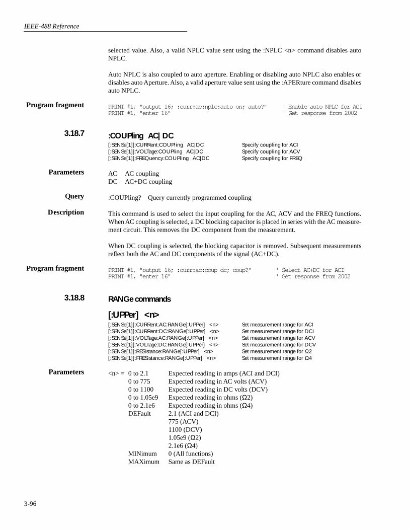
IEEE-488 Reference
3-96
selected value. Also, a valid NPLC value sent using the :NPLC <n> command disables autoNPLC.
Auto NPLC is also coupled to auto aperture. Enabling or disabling auto NPLC also enables ordisables auto Aperture. Also, a valid aperture value sent using the :APERture command disablesauto NPLC.
PRINT #1, "output 16; :curr:ac:nplc:auto on; auto?" ' Enable auto NPLC for ACIPRINT #1, "enter 16" ' Get response from 2002
:COUPling AC|DC[:SENSe[1]]:CURRent:COUPling AC|DC Specify coupling for ACI[:SENSe[1]]:VOLTage:COUPling AC|DC Specify coupling for ACV[:SENSe[1]]:FREQuency:COUPling AC|DC Specify coupling for FREQ
AC AC couplingDC AC+DC coupling
:COUPling? Query currently programmed coupling
This command is used to select the input coupling for the AC, ACV and the FREQ functions.When AC coupling is selected, a DC blocking capacitor is placed in series with the AC measure-ment circuit. This removes the DC component from the measurement.
When DC coupling is selected, the blocking capacitor is removed. Subsequent measurementsreflect both the AC and DC components of the signal (AC+DC).
PRINT #1, "output 16; :curr:ac:coup dc; coup?" ' Select AC+DC for ACIPRINT #1, "enter 16" ' Get response from 2002
RANGe commands
[:UPPer] <n>[:SENSe[1]]:CURRent:AC:RANGe[:UPPer] <n> Set measurement range for ACI[:SENSe[1]]:CURRent:DC:RANGe[:UPPer] <n> Set measurement range for DCI[:SENSe[1]]:VOLTage:AC:RANGe[:UPPer] <n> Set measurement range for ACV[:SENSe[1]]:VOLTage:DC:RANGe[:UPPer] <n> Set measurement range for DCV[:SENSe[1]]:RESistance:RANGe[:UPPer] <n> Set measurement range for Ω2[:SENSe[1]]:FRESistance:RANGe[:UPPer] <n> Set measurement range for Ω4
<n> = 0 to 2.1 Expected reading in amps (ACI and DCI)0 to 775 Expected reading in AC volts (ACV)0 to 1100 Expected reading in DC volts (DCV)0 to 1.05e9 Expected reading in ohms (Ω2)0 to 2.1e6 Expected reading in ohms (Ω4)DEFault 2.1 (ACI and DCI)
775 (ACV)1100 (DCV)1.05e9 (Ω2)2.1e6 (Ω4)
MINimum 0 (All functions)MAXimum Same as DEFault
Program fragment
3.18.7
Parameters
Query
Description
Program fragment
3.18.8
Parameters
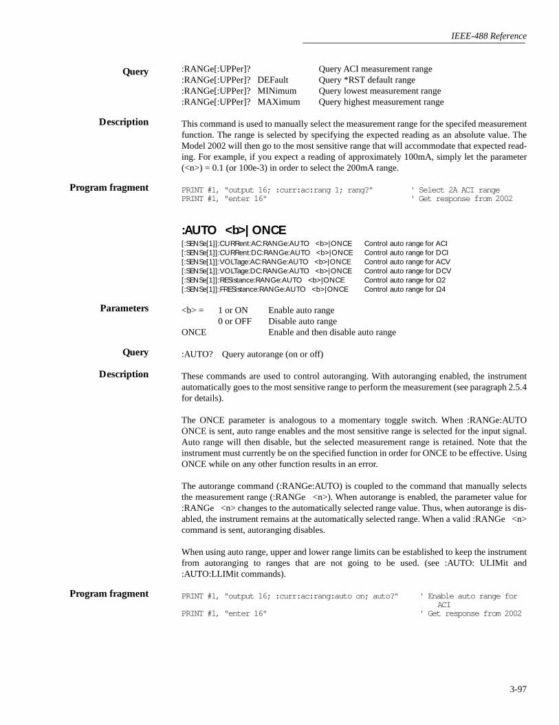
IEEE-488 Reference
3-97
:RANGe[:UPPer]? Query ACI measurement range:RANGe[:UPPer]? DEFault Query *RST default range:RANGe[:UPPer]? MINimum Query lowest measurement range:RANGe[:UPPer]? MAXimum Query highest measurement range
This command is used to manually select the measurement range for the specifed measurementfunction. The range is selected by specifying the expected reading as an absolute value. TheModel 2002 will then go to the most sensitive range that will accommodate that expected read-ing. For example, if you expect a reading of approximately 100mA, simply let the parameter(<n>) = 0.1 (or 100e-3) in order to select the 200mA range.
PRINT #1, "output 16; :curr:ac:rang 1; rang?" ' Select 2A ACI rangePRINT #1, "enter 16" ' Get response from 2002
:AUTO <b>|ONCE[:SENSe[1]]:CURRent:AC:RANGe:AUTO <b>|ONCE Control auto range for ACI[:SENSe[1]]:CURRent:DC:RANGe:AUTO <b>|ONCE Control auto range for DCI[:SENSe[1]]:VOLTage:AC:RANGe:AUTO <b>|ONCE Control auto range for ACV[:SENSe[1]]:VOLTage:DC:RANGe:AUTO <b>|ONCE Control auto range for DCV[:SENSe[1]]:RESistance:RANGe:AUTO <b>|ONCE Control auto range for Ω2[:SENSe[1]]:FRESistance:RANGe:AUTO <b>|ONCE Control auto range for Ω4
<b> = 1 or ON Enable auto range0 or OFF Disable auto range
ONCE Enable and then disable auto range
:AUTO? Query autorange (on or off)
These commands are used to control autoranging. With autoranging enabled, the instrumentautomatically goes to the most sensitive range to perform the measurement (see paragraph 2.5.4for details).
The ONCE parameter is analogous to a momentary toggle switch. When :RANGe:AUTOONCE is sent, auto range enables and the most sensitive range is selected for the input signal.Auto range will then disable, but the selected measurement range is retained. Note that theinstrument must currently be on the specified function in order for ONCE to be effective. UsingONCE while on any other function results in an error.
The autorange command (:RANGe:AUTO) is coupled to the command that manually selectsthe measurement range (:RANGe <n>). When autorange is enabled, the parameter value for:RANGe <n> changes to the automatically selected range value. Thus, when autorange is dis-abled, the instrument remains at the automatically selected range. When a valid :RANGe <n>command is sent, autoranging disables.
When using auto range, upper and lower range limits can be established to keep the instrumentfrom autoranging to ranges that are not going to be used. (see :AUTO: ULIMit and:AUTO:LLIMit commands).
PRINT #1, "output 16; :curr:ac:rang:auto on; auto?" ' Enable auto range for ACI
PRINT #1, "enter 16" ' Get response from 2002
Query
Description
Program fragment
Parameters
Query
Description
Program fragment

IEEE-488 Reference
3-98
:ULIMit <n>[:SENSe[1]]:CURRent:AC:RANGe:AUTO:ULIMit <n> Set upper limit for ACI[:SENSe[1]]:CURRent:DC:RANGe:AUTO:ULIMit <n> Set upper limit for DCI[:SENSe[1]]:VOLTage:AC:RANGe:AUTO:ULIMit <n> Set upper limit for ACV[:SENSe[1]]:VOLTage:DC:RANGe:AUTO:ULIMit <n> Set upper limit for DCV[:SENSe[1]]:RESistance:RANGe:AUTO:ULIMit <n> Set upper limit for Ω2[:SENSe[1]]:FRESistance:RANGe:AUTO:ULIMit <n> Set upper limit for Ω4
:LLIMit <n>[:SENSe[1]]:CURRent:AC:RANGe:AUTO:LLIMit <n> Set lower limit for ACI[:SENSe[1]]:CURRent:DC:RANGe:AUTO:LLIMit <n> Set lower limit for DCI[:SENSe[1]]:VOLTage:AC:RANGe:AUTO:LLIMit <n> Set lower limit for ACV[:SENSe[1]]:VOLTage:DC:RANGe:AUTO:LLIMit <n> Set lower limit for DCV[:SENSe[1]]:RESistance:RANGe:AUTO:LLIMit <n> Set lower limit for Ω2[:SENSe[1]:FRESistance:RANGe:AUTO:LLIMit <n> Set lower limit for Ω4
<n> = 0 to 2.1 Range limit for ACI and DCI0 to 775 Range limit for ACV0 to 1100 Range limit for DCV0 to 1.05e9 Range limit for Ω20 to 2.1e6 Range limit for Ω4DEFault 2.1 (ACI and DCI)
775 (ACV)1100 (DCV)1.05e9 (Ω2)2.1e6 (Ω4)
MINimum 0 (All functions)MAXimum Same as DEFault
:ULIMit? Query upper range limit:ULIMit? DEFault Query *RST default upper limit:ULIMit? MINimum Query lowest allowable upper limit:ULIMit? MAXimum Query largest allowable upper limit:LLIMit? Query lower range limit:LLIMit? DEFault Query *RST default lower limit:LLIMit? MINimum Query lowest allowable lower limit:LLIMit? MAXimum Query largest allowable lower limit
Automatic range changes slow down the reading rate. By setting upper and lower measurementrange limits, you can prevent inadvertent range changes to ranges that you are not going to use.
The upper range limit is selected by specifying the maximum expected reading that you expectto measure. For example, if the maximum expected reading is approximately 100mA, let theparameter (<n>) = 0.1 (or 100e-3). The lowest (most sensitive) range that can measure 100mAis the 200mA range. Thus, the 200mA range is selected as the upper range limit. With this upperlimit, the instrument cannot uprange to the 2A measurement range.
The lower range limit is selected by specifying the lowest expected reading that you expect tomeasure.
PRINT #1, "output 16; :curr:ac:rang:auto:ulim 1" ' Set upper limit for ACI' Set lower limit and query
limitsPRINT #1, "output 16; :curr:ac:rang:auto:llim 10e-3; ulim?; llim?"PRINT #1, "enter 16" ' Get response from 2002
Parameters
Query
Description
Program fragment
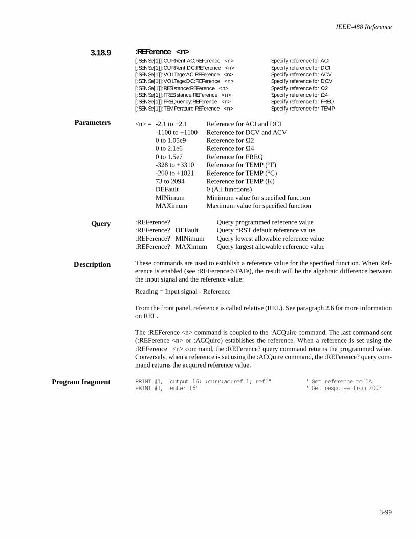
IEEE-488 Reference
3-99
:REFerence <n>[:SENSe[1]]:CURRent:AC:REFerence <n> Specify reference for ACI[:SENSe[1]]:CURRent:DC:REFerence <n> Specify reference for DCI[:SENSe[1]]:VOLTage:AC:REFerence <n> Specify reference for ACV[:SENSe[1]]:VOLTage:DC:REFerence <n> Specify reference for DCV[:SENSe[1]]:RESistance:REFerence <n> Specify reference for Ω2[:SENSe[1]]:FRESistance:REFerence <n> Specify reference for Ω4[:SENSe[1]]:FREQuency:REFerence <n> Specify reference for FREQ[:SENSe[1]]:TEMPerature:REFerence <n> Specify reference for TEMP
<n> = -2.1 to +2.1 Reference for ACI and DCI-1100 to +1100 Reference for DCV and ACV0 to 1.05e9 Reference for Ω20 to 2.1e6 Reference for Ω40 to 1.5e7 Reference for FREQ-328 to +3310 Reference for TEMP (°F)-200 to +1821 Reference for TEMP (°C)73 to 2094 Reference for TEMP (K)DEFault 0 (All functions)MINimum Minimum value for specified functionMAXimum Maximum value for specified function
:REFerence? Query programmed reference value:REFerence? DEFault Query *RST default reference value:REFerence? MINimum Query lowest allowable reference value:REFerence? MAXimum Query largest allowable reference value
These commands are used to establish a reference value for the specified function. When Ref-erence is enabled (see :REFerence:STATe), the result will be the algebraic difference betweenthe input signal and the reference value:
Reading = Input signal - Reference
From the front panel, reference is called relative (REL). See paragraph 2.6 for more informationon REL.
The :REFerence <n> command is coupled to the :ACQuire command. The last command sent(:REFerence <n> or :ACQuire) establishes the reference. When a reference is set using the:REFerence <n> command, the :REFerence? query command returns the programmed value.Conversely, when a reference is set using the :ACQuire command, the :REFerence? query com-mand returns the acquired reference value.
PRINT #1, "output 16; :curr:ac:ref 1; ref?" ' Set reference to 1APRINT #1, "enter 16" ' Get response from 2002
3.18.9
Parameters
Query
Description
Program fragment
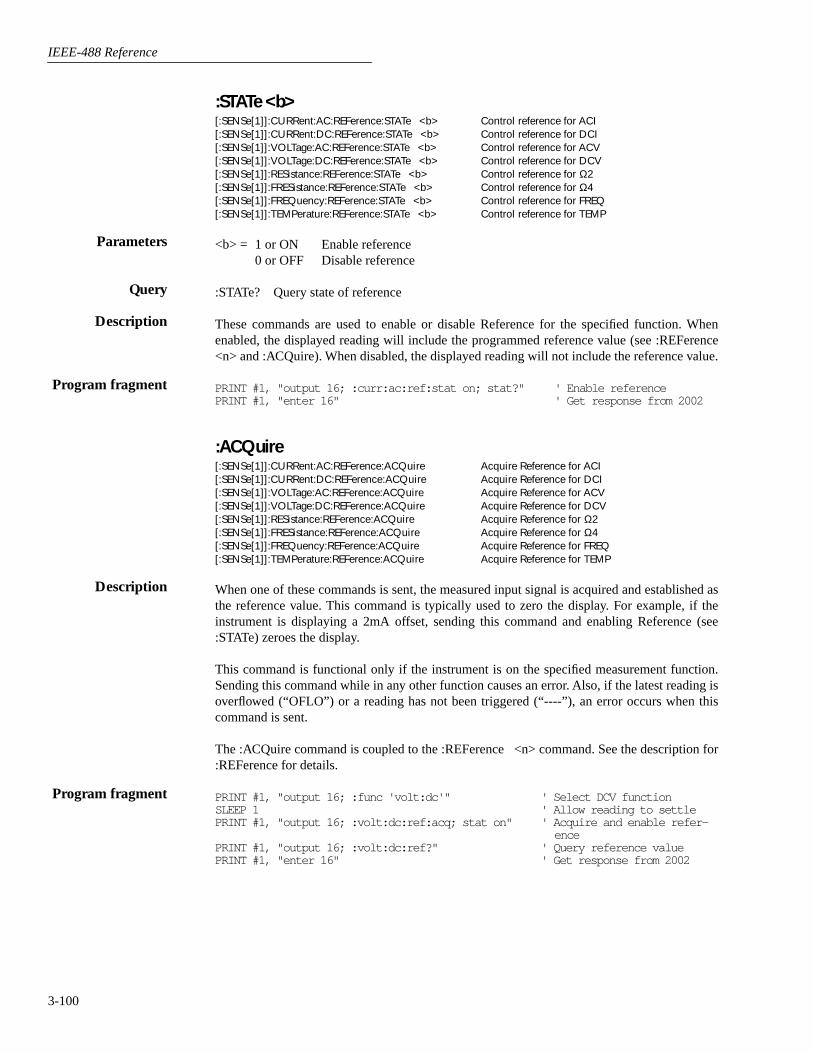
IEEE-488 Reference
3-100
:STATe <b>[:SENSe[1]]:CURRent:AC:REFerence:STATe <b> Control reference for ACI[:SENSe[1]]:CURRent:DC:REFerence:STATe <b> Control reference for DCI[:SENSe[1]]:VOLTage:AC:REFerence:STATe <b> Control reference for ACV[:SENSe[1]]:VOLTage:DC:REFerence:STATe <b> Control reference for DCV[:SENSe[1]]:RESistance:REFerence:STATe <b> Control reference for Ω2[:SENSe[1]]:FRESistance:REFerence:STATe <b> Control reference for Ω4[:SENSe[1]]:FREQuency:REFerence:STATe <b> Control reference for FREQ[:SENSe[1]]:TEMPerature:REFerence:STATe <b> Control reference for TEMP
<b> = 1 or ON Enable reference0 or OFF Disable reference
:STATe? Query state of reference
These commands are used to enable or disable Reference for the specified function. Whenenabled, the displayed reading will include the programmed reference value (see :REFerence<n> and :ACQuire). When disabled, the displayed reading will not include the reference value.
PRINT #1, "output 16; :curr:ac:ref:stat on; stat?" ' Enable referencePRINT #1, "enter 16" ' Get response from 2002
:ACQuire[:SENSe[1]]:CURRent:AC:REFerence:ACQuire Acquire Reference for ACI[:SENSe[1]]:CURRent:DC:REFerence:ACQuire Acquire Reference for DCI[:SENSe[1]]:VOLTage:AC:REFerence:ACQuire Acquire Reference for ACV[:SENSe[1]]:VOLTage:DC:REFerence:ACQuire Acquire Reference for DCV[:SENSe[1]]:RESistance:REFerence:ACQuire Acquire Reference for Ω2[:SENSe[1]]:FRESistance:REFerence:ACQuire Acquire Reference for Ω4[:SENSe[1]]:FREQuency:REFerence:ACQuire Acquire Reference for FREQ[:SENSe[1]]:TEMPerature:REFerence:ACQuire Acquire Reference for TEMP
When one of these commands is sent, the measured input signal is acquired and established asthe reference value. This command is typically used to zero the display. For example, if theinstrument is displaying a 2mA offset, sending this command and enabling Reference (see:STATe) zeroes the display.
This command is functional only if the instrument is on the specified measurement function.Sending this command while in any other function causes an error. Also, if the latest reading isoverflowed (“OFLO”) or a reading has not been triggered (“----”), an error occurs when thiscommand is sent.
The :ACQuire command is coupled to the :REFerence <n> command. See the description for:REFerence for details.
PRINT #1, "output 16; :func 'volt:dc'" ' Select DCV functionSLEEP 1 ' Allow reading to settlePRINT #1, "output 16; :volt:dc:ref:acq; stat on" ' Acquire and enable refer-
encePRINT #1, "output 16; :volt:dc:ref?" ' Query reference valuePRINT #1, "enter 16" ' Get response from 2002
Parameters
Query
Description
Program fragment
Description
Program fragment
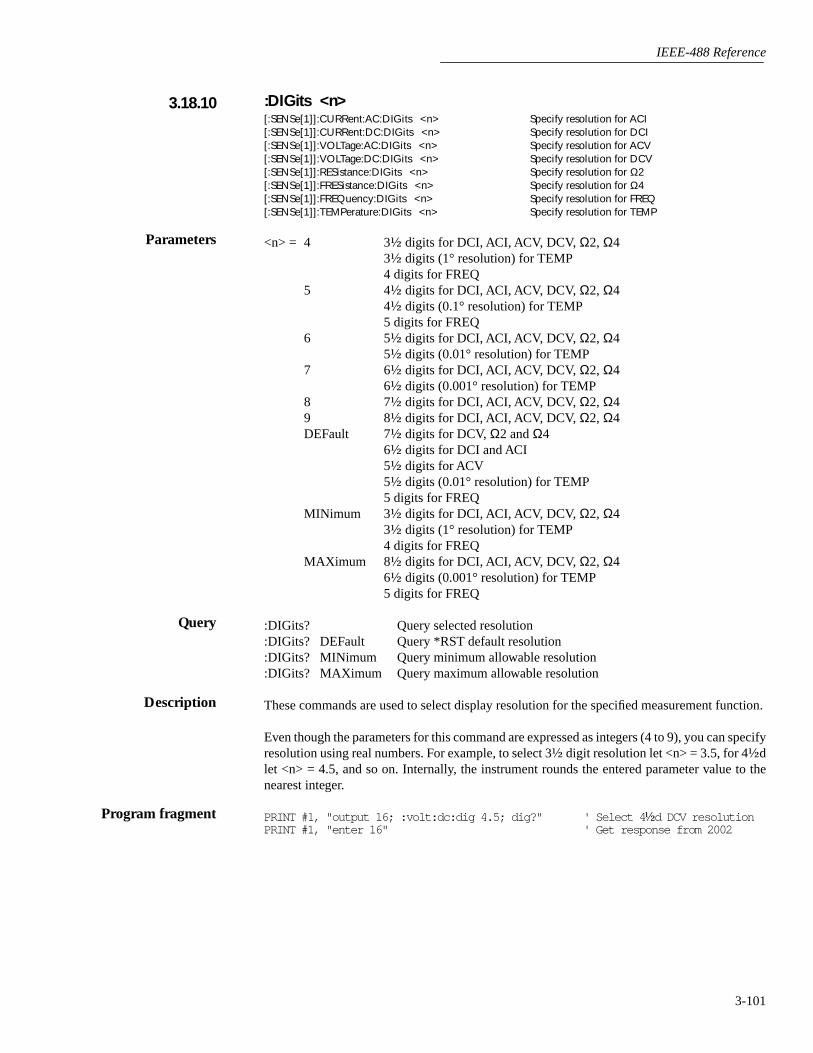
IEEE-488 Reference
3-101
:DIGits <n>[:SENSe[1]]:CURRent:AC:DIGits <n> Specify resolution for ACI[:SENSe[1]]:CURRent:DC:DIGits <n> Specify resolution for DCI[:SENSe[1]]:VOLTage:AC:DIGits <n> Specify resolution for ACV[:SENSe[1]]:VOLTage:DC:DIGits <n> Specify resolution for DCV[:SENSe[1]]:RESistance:DIGits <n> Specify resolution for Ω2[:SENSe[1]]:FRESistance:DIGits <n> Specify resolution for Ω4[:SENSe[1]]:FREQuency:DIGits <n> Specify resolution for FREQ[:SENSe[1]]:TEMPerature:DIGits <n> Specify resolution for TEMP
<n> = 4 3½ digits for DCI, ACI, ACV, DCV, Ω2, Ω43½ digits (1° resolution) for TEMP4 digits for FREQ
5 4½ digits for DCI, ACI, ACV, DCV, Ω2, Ω44½ digits (0.1° resolution) for TEMP5 digits for FREQ
6 5½ digits for DCI, ACI, ACV, DCV, Ω2, Ω45½ digits (0.01° resolution) for TEMP
7 6½ digits for DCI, ACI, ACV, DCV, Ω2, Ω46½ digits (0.001° resolution) for TEMP
8 7½ digits for DCI, ACI, ACV, DCV, Ω2, Ω49 8½ digits for DCI, ACI, ACV, DCV, Ω2, Ω4DEFault 7½ digits for DCV, Ω2 and Ω4
6½ digits for DCI and ACI5½ digits for ACV5½ digits (0.01° resolution) for TEMP5 digits for FREQ
MINimum 3½ digits for DCI, ACI, ACV, DCV, Ω2, Ω43½ digits (1° resolution) for TEMP4 digits for FREQ
MAXimum 8½ digits for DCI, ACI, ACV, DCV, Ω2, Ω46½ digits (0.001° resolution) for TEMP5 digits for FREQ
:DIGits? Query selected resolution:DIGits? DEFault Query *RST default resolution:DIGits? MINimum Query minimum allowable resolution:DIGits? MAXimum Query maximum allowable resolution
These commands are used to select display resolution for the specified measurement function.
Even though the parameters for this command are expressed as integers (4 to 9), you can specifyresolution using real numbers. For example, to select 3½ digit resolution let <n> = 3.5, for 4½dlet <n> = 4.5, and so on. Internally, the instrument rounds the entered parameter value to thenearest integer.
PRINT #1, "output 16; :volt:dc:dig 4.5; dig?" ' Select 4 ½d DCV resolutionPRINT #1, "enter 16" ' Get response from 2002
3.18.10
Parameters
Query
Description
Program fragment

IEEE-488 Reference
3-102
:AUTO <b>|ONCE[:SENSe[1]]:CURRent:AC:DIGits:AUTO <b>|ONCE Control auto resolution for ACI[:SENSe[1]]:CURRent:DC:DIGits:AUTO <b>|ONCE Control auto resolution for DCI[:SENSe[1]]:VOLTage:AC:DIGits:AUTO <b>|ONCE Control auto resolution for ACV[:SENSe[1]]:VOLTage:DC:DIGits:AUTO <b>|ONCE Control auto resolution for DCV[:SENSe[1]]:RESistance:DIGits:AUTO <b>|ONCE Control auto resolution for Ω2[:SENSe[1]]:FRESistance:DIGits:AUTO <b>|ONCE Control auto resolution for Ω4[:SENSe[1]]:TEMPerature:DIGits:AUTO <b>|ONCE Control auto resolution for TEMP
<b> = 1 or ON Enable auto resolution0 or OFF Disable auto resolution
ONCE Enable and then disable auto resolution
:AUTO? Query state of auto resolution
These commands are used to enable or disable auto resolution for the specified function. Withauto resolution selected, the instrument automatically selects the optimum resolution for thepresent integration time setting (see Tables 2-10, 2-15, 2-20 and 2-25).
The ONCE parameter is analogous to a momentary toggle switch. When :AUTO ONCE is sent,auto resolution turns on momentarily and then disables. While enabled, resolution is selectedautomatically. Auto resolution then disables but the selected value is retained.
The auto resolution command (:DIGits:AUTO) is coupled to the command that manually selectsresolution (:DIGits <n>). When auto resolution is enabled, the parameter value for :DIGits<n> changes to the automatically selected resolution value. Thus, when auto resolution is dis-abled, the instrument remains at the automatically selected resolution.
PRINT #1, "output 16; :volt:dc:dig:auto on; auto?" ' Enable auto resolutionPRINT #1, "enter 16" ' Get response from 2002
:AVERage commands
The :AVERage commands are used to configure and control the filter. See paragraph 2.9 fordetails.
:TCONtrol <name>[:SENSe[1]]:CURRent:AC:AVERage:TCONtrol <name> Select filter type for ACI[:SENSe[1]]:CURRent:DC:AVERage:TCONtrol <name> Select filter type for DCI[:SENSe[1]]:VOLTage:AC:AVERage:TCONtrol <name> Select filter type for ACV[:SENSe[1]]:VOLTage:DC:AVERage:TCONtrol <name> Select filter type for DCV[:SENSe[1]]:RESistance:AVERage:TCONtrol <name> Select filter type for Ω2[:SENSe[1]]:FRESistance:AVERage:TCONtrol <name> Select filter type for Ω4[:SENSe[1]]:TEMPerature:AVERage:TCONtrol <name> Select filter type for TEMP
<name> = REPeat Select repeating filterMOVing Select moving filter
:TCONtrol? Query filter type
These commands are used to select the type of averaging filter (REPeat or MOVing) for thespecified function.
Parameters
Query
Description
Program fragment
3.18.11
Parameters
Query
Description
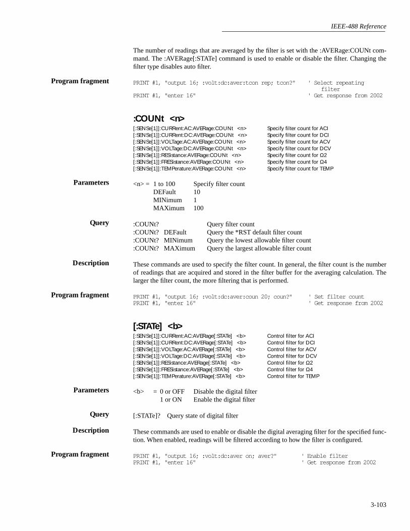
IEEE-488 Reference
3-103
The number of readings that are averaged by the filter is set with the :AVERage:COUNt com-mand. The :AVERage[:STATe] command is used to enable or disable the filter. Changing thefilter type disables auto filter.
PRINT #1, "output 16; :volt:dc:aver:tcon rep; tcon?" ' Select repeating filter
PRINT #1, "enter 16" ' Get response from 2002
:COUNt <n>[:SENSe[1]]:CURRent:AC:AVERage:COUNt <n> Specify filter count for ACI[:SENSe[1]]:CURRent:DC:AVERage:COUNt <n> Specify filter count for DCI[:SENSe[1]]:VOLTage:AC:AVERage:COUNt <n> Specify filter count for ACV[:SENSe[1]]:VOLTage:DC:AVERage:COUNt <n> Specify filter count for DCV[:SENSe[1]]:RESistance:AVERage:COUNt <n> Specify filter count for Ω2[:SENSe[1]]:FRESistance:AVERage:COUNt <n> Specify filter count for Ω4[:SENSe[1]]:TEMPerature:AVERage:COUNt <n> Specify filter count for TEMP
<n> = 1 to 100 Specify filter countDEFault 10MINimum 1MAXimum 100
:COUNt? Query filter count:COUNt? DEFault Query the *RST default filter count:COUNt? MINimum Query the lowest allowable filter count:COUNt? MAXimum Query the largest allowable filter count
These commands are used to specify the filter count. In general, the filter count is the numberof readings that are acquired and stored in the filter buffer for the averaging calculation. Thelarger the filter count, the more filtering that is performed.
PRINT #1, "output 16; :volt:dc:aver:coun 20; coun?" ' Set filter countPRINT #1, "enter 16" ' Get response from 2002
[:STATe] <b>[:SENSe[1]]:CURRent:AC:AVERage[:STATe] <b> Control filter for ACI[:SENSe[1]]:CURRent:DC:AVERage[:STATe] <b> Control filter for DCI[:SENSe[1]]:VOLTage:AC:AVERage[:STATe] <b> Control filter for ACV[:SENSe[1]]:VOLTage:DC:AVERage[:STATe] <b> Control filter for DCV[:SENSe[1]]:RESistance:AVERage[:STATe] <b> Control filter for Ω2[:SENSe[1]]:FRESistance:AVERage[:STATe] <b> Control filter for Ω4[:SENSe[1]]:TEMPerature:AVERage[:STATe] <b> Control filter for TEMP
<b> = 0 or OFF Disable the digital filter1 or ON Enable the digital filter
[:STATe]? Query state of digital filter
These commands are used to enable or disable the digital averaging filter for the specified func-tion. When enabled, readings will be filtered according to how the filter is configured.
PRINT #1, "output 16; :volt:dc:aver on; aver?" ' Enable filterPRINT #1, "enter 16" ' Get response from 2002
Program fragment
Parameters
Query
Description
Program fragment
Parameters
Query
Description
Program fragment
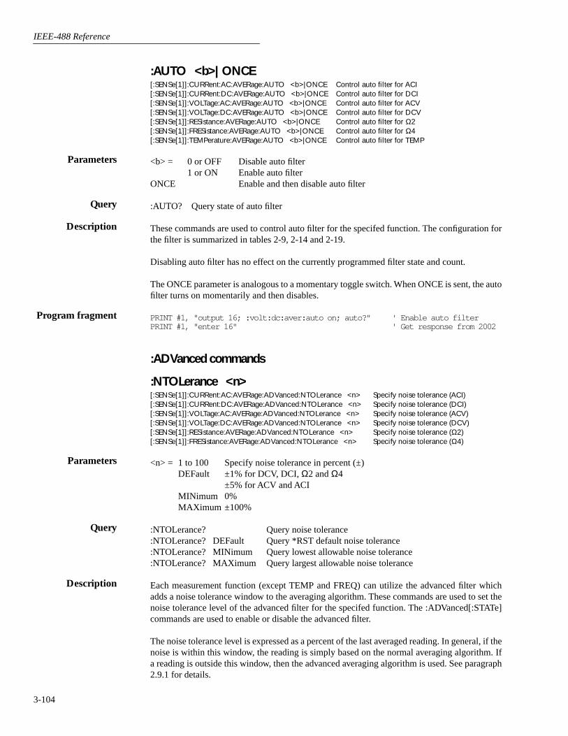
IEEE-488 Reference
3-104
:AUTO <b>|ONCE[:SENSe[1]]:CURRent:AC:AVERage:AUTO <b>|ONCE Control auto filter for ACI[:SENSe[1]]:CURRent:DC:AVERage:AUTO <b>|ONCE Control auto filter for DCI[:SENSe[1]]:VOLTage:AC:AVERage:AUTO <b>|ONCE Control auto filter for ACV[:SENSe[1]]:VOLTage:DC:AVERage:AUTO <b>|ONCE Control auto filter for DCV[:SENSe[1]]:RESistance:AVERage:AUTO <b>|ONCE Control auto filter for Ω2[:SENSe[1]]:FRESistance:AVERage:AUTO <b>|ONCE Control auto filter for Ω4[:SENSe[1]]:TEMPerature:AVERage:AUTO <b>|ONCE Control auto filter for TEMP
<b> = 0 or OFF Disable auto filter1 or ON Enable auto filter
ONCE Enable and then disable auto filter
:AUTO? Query state of auto filter
These commands are used to control auto filter for the specifed function. The configuration forthe filter is summarized in tables 2-9, 2-14 and 2-19.
Disabling auto filter has no effect on the currently programmed filter state and count.
The ONCE parameter is analogous to a momentary toggle switch. When ONCE is sent, the autofilter turns on momentarily and then disables.
PRINT #1, "output 16; :volt:dc:aver:auto on; auto?" ' Enable auto filterPRINT #1, "enter 16" ' Get response from 2002
:ADVanced commands
:NTOLerance <n>[:SENSe[1]]:CURRent:AC:AVERage:ADVanced:NTOLerance <n> Specify noise tolerance (ACI)[:SENSe[1]]:CURRent:DC:AVERage:ADVanced:NTOLerance <n> Specify noise tolerance (DCI)[:SENSe[1]]:VOLTage:AC:AVERage:ADVanced:NTOLerance <n> Specify noise tolerance (ACV)[:SENSe[1]]:VOLTage:DC:AVERage:ADVanced:NTOLerance <n> Specify noise tolerance (DCV)[:SENSe[1]]:RESistance:AVERage:ADVanced:NTOLerance <n> Specify noise tolerance (Ω2)[:SENSe[1]]:FRESistance:AVERage:ADVanced:NTOLerance <n> Specify noise tolerance (Ω4)
<n> = 1 to 100 Specify noise tolerance in percent (±)DEFault ±1% for DCV, DCI, Ω2 and Ω4
±5% for ACV and ACIMINimum 0%MAXimum ±100%
:NTOLerance? Query noise tolerance:NTOLerance? DEFault Query *RST default noise tolerance:NTOLerance? MINimum Query lowest allowable noise tolerance:NTOLerance? MAXimum Query largest allowable noise tolerance
Each measurement function (except TEMP and FREQ) can utilize the advanced filter whichadds a noise tolerance window to the averaging algorithm. These commands are used to set thenoise tolerance level of the advanced filter for the specifed function. The :ADVanced[:STATe]commands are used to enable or disable the advanced filter.
The noise tolerance level is expressed as a percent of the last averaged reading. In general, if thenoise is within this window, the reading is simply based on the normal averaging algorithm. Ifa reading is outside this window, then the advanced averaging algorithm is used. See paragraph2.9.1 for details.
Parameters
Query
Description
Program fragment
Parameters
Query
Description

IEEE-488 Reference
3-105
PRINT #1, "output 16; :volt:dc:aver:adv:ntol 20; ntol?" ' Get noise tolerance
PRINT #1, "enter 16" ' Get response from 2002
[:STATe] <b>[:SENSe[1]]:CURRent:AC:AVERage:ADVanced[:STATe] <b> Control advanced filter for ACI[:SENSe[1]]:CURRent:DC:AVERage:ADVanced[:STATe] <b> Control advanced filter for DCI[:SENSe[1]]:VOLTage:AC:AVERage:ADVanced[:STATe] <b> Control advanced filter for ACV[:SENSe[1]]:VOLTage:DC:AVERage:ADVanced[:STATe] <b> Control advanced filter for DCV[:SENSe[1]]:RESistance:AVERage:ADVanced[:STATe] <b> Control advanced filter for Ω2[:SENSe[1]]:FRESistance:AVERage:ADVanced[:STATe] <b> Control advanced filter for Ω4
<b> = 0 or OFF Disable advanced filter1 or ON Enable advanced filter
[:STATe]? Query state of advanced filter
These commands are used to enable or disable the advanced filter for the specified function. The:ADVanced:NTOLerance commands are used to set tolerance levels.
PRINT #1, "output 16; :volt:dc:aver:adv on; adv?" ' Enable advanced filterPRINT #1, "enter 16" ' Get response from 2002
:DETector commands
[:FUNCTION] <name>[:SENSe[1]]:CURRent:AC:DETector[:FUNCTION] <name> Specify detector for ACI[:SENSe[1]]:VOLTage:AC:DETector[:FUNCTION] <name> Specify detector for ACV
ACI:
<name> = RMS AC RMS amps measurementsAVERage AC average amps measurements
ACV:
<name> = RMS AC RMS volts measurementsAVERage AC average volts measurementsLFRMs Low frequency AC volts measurementsPEAK AC peak volts measurementsNPEak AC negative peak spike volts measurementsPPEak AC positive peak spike volts measurements
[:FUNCtion]? Query selected measurement type
These commands are used to select the measurement type for the ACI and ACV functions. Referto paragraphs 2.4.1 (ACV) and 2.4.2 (ACI) for details on AC-TYPE.
PRINT #1, "output 16; :curr:ac:det aver; det?" ' Select average detectorPRINT #1, "enter 16" ' Get response from 2002
Program fragment
Parameters
Query
Description
Program fragment
3.18.12
Parameters
Query
Description
Program fragment
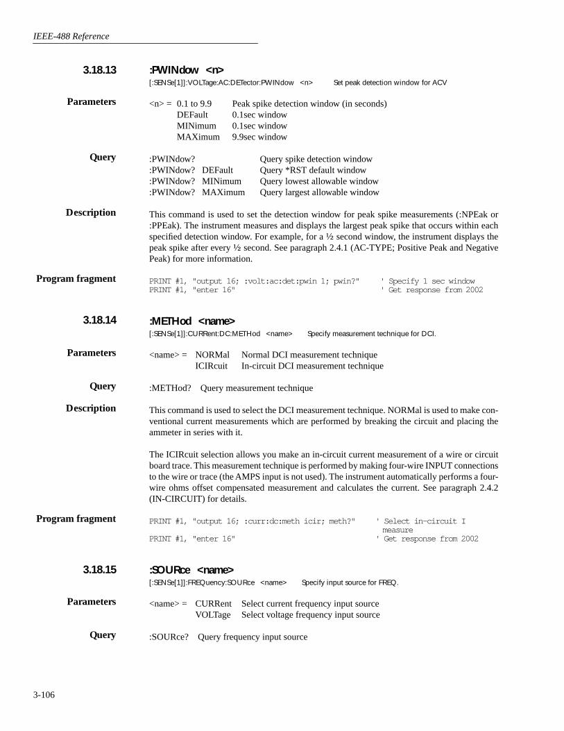
IEEE-488 Reference
3-106
:PWINdow <n>[:SENSe[1]]:VOLTage:AC:DETector:PWINdow <n> Set peak detection window for ACV
<n> = 0.1 to 9.9 Peak spike detection window (in seconds)DEFault 0.1sec windowMINimum 0.1sec windowMAXimum 9.9sec window
:PWINdow? Query spike detection window:PWINdow? DEFault Query *RST default window:PWINdow? MINimum Query lowest allowable window:PWINdow? MAXimum Query largest allowable window
This command is used to set the detection window for peak spike measurements (:NPEak or:PPEak). The instrument measures and displays the largest peak spike that occurs within eachspecified detection window. For example, for a ½ second window, the instrument displays thepeak spike after every ½ second. See paragraph 2.4.1 (AC-TYPE; Positive Peak and NegativePeak) for more information.
PRINT #1, "output 16; :volt:ac:det:pwin 1; pwin?" ' Specify 1 sec windowPRINT #1, "enter 16" ' Get response from 2002
:METHod <name>[:SENSe[1]]:CURRent:DC:METHod <name> Specify measurement technique for DCI.
<name> = NORMal Normal DCI measurement techniqueICIRcuit In-circuit DCI measurement technique
:METHod? Query measurement technique
This command is used to select the DCI measurement technique. NORMal is used to make con-ventional current measurements which are performed by breaking the circuit and placing theammeter in series with it.
The ICIRcuit selection allows you make an in-circuit current measurement of a wire or circuitboard trace. This measurement technique is performed by making four-wire INPUT connectionsto the wire or trace (the AMPS input is not used). The instrument automatically performs a four-wire ohms offset compensated measurement and calculates the current. See paragraph 2.4.2(IN-CIRCUIT) for details.
PRINT #1, "output 16; :curr:dc:meth icir; meth?" ' Select in-circuit I measure
PRINT #1, "enter 16" ' Get response from 2002
:SOURce <name>[:SENSe[1]]:FREQuency:SOURce <name> Specify input source for FREQ.
<name> = CURRent Select current frequency input sourceVOLTage Select voltage frequency input source
:SOURce? Query frequency input source
3.18.13
Parameters
Query
Description
Program fragment
3.18.14
Parameters
Query
Description
Program fragment
3.18.15
Parameters
Query
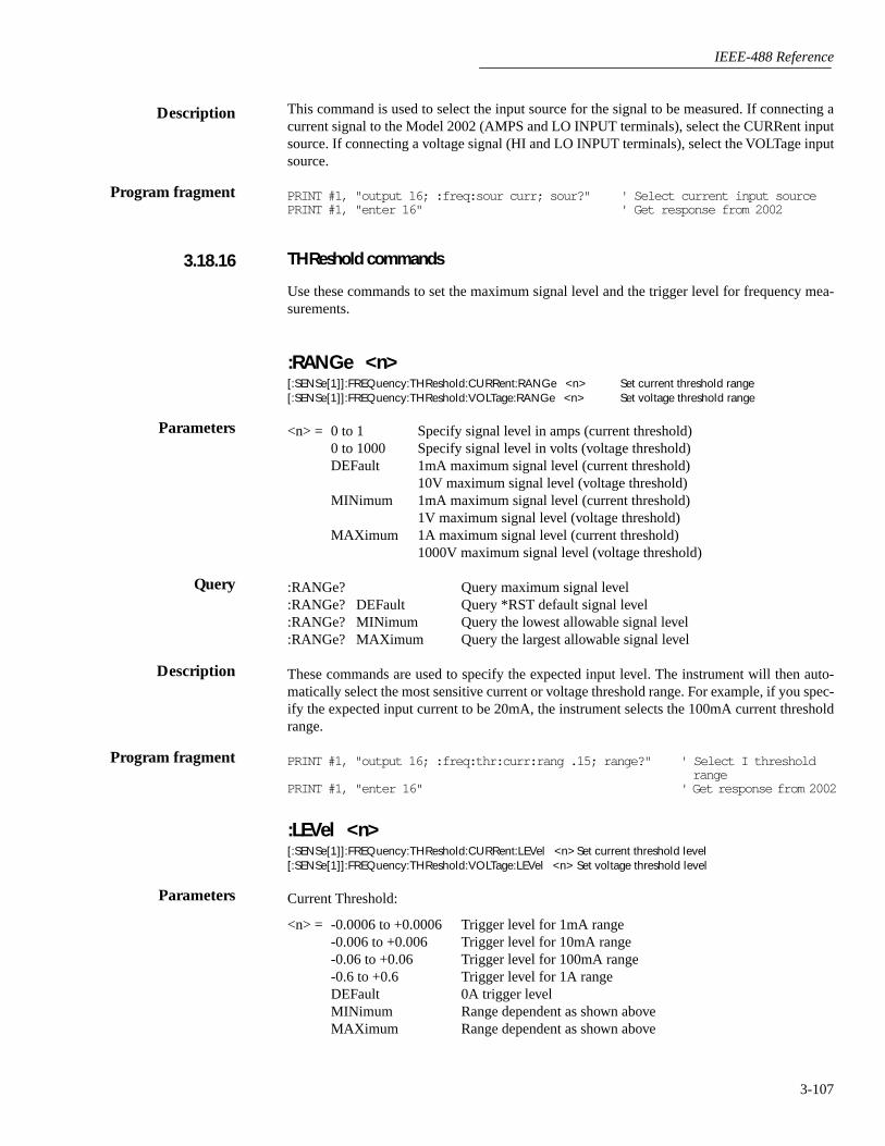
IEEE-488 Reference
3-107
This command is used to select the input source for the signal to be measured. If connecting acurrent signal to the Model 2002 (AMPS and LO INPUT terminals), select the CURRent inputsource. If connecting a voltage signal (HI and LO INPUT terminals), select the VOLTage inputsource.
PRINT #1, "output 16; :freq:sour curr; sour?" ' Select current input sourcePRINT #1, "enter 16" ' Get response from 2002
THReshold commands
Use these commands to set the maximum signal level and the trigger level for frequency mea-surements.
:RANGe <n>[:SENSe[1]]:FREQuency:THReshold:CURRent:RANGe <n> Set current threshold range[:SENSe[1]]:FREQuency:THReshold:VOLTage:RANGe <n> Set voltage threshold range
<n> = 0 to 1 Specify signal level in amps (current threshold)0 to 1000 Specify signal level in volts (voltage threshold)DEFault 1mA maximum signal level (current threshold)
10V maximum signal level (voltage threshold)MINimum 1mA maximum signal level (current threshold)
1V maximum signal level (voltage threshold)MAXimum 1A maximum signal level (current threshold)
1000V maximum signal level (voltage threshold)
:RANGe? Query maximum signal level:RANGe? DEFault Query *RST default signal level:RANGe? MINimum Query the lowest allowable signal level:RANGe? MAXimum Query the largest allowable signal level
These commands are used to specify the expected input level. The instrument will then auto-matically select the most sensitive current or voltage threshold range. For example, if you spec-ify the expected input current to be 20mA, the instrument selects the 100mA current thresholdrange.
PRINT #1, "output 16; :freq:thr:curr:rang .15; range?" ' Select I threshold range
PRINT #1, "enter 16" ' Get response from 2002
:LEVel <n>[:SENSe[1]]:FREQuency:THReshold:CURRent:LEVel <n> Set current threshold level[:SENSe[1]]:FREQuency:THReshold:VOLTage:LEVel <n> Set voltage threshold level
Current Threshold:
<n> = -0.0006 to +0.0006 Trigger level for 1mA range-0.006 to +0.006 Trigger level for 10mA range-0.06 to +0.06 Trigger level for 100mA range-0.6 to +0.6 Trigger level for 1A rangeDEFault 0A trigger levelMINimum Range dependent as shown aboveMAXimum Range dependent as shown above
Description
Program fragment
3.18.16
Parameters
Query
Description
Program fragment
Parameters

IEEE-488 Reference
3-108
Voltage Threshold:
<n> = -0.6 to +0.6 Trigger level for 1V range-6 to +6 Trigger level for 10V range-60 to +60 Trigger level for 100V range-600 to +600 Trigger level for 1000V rangeDEFault 0V trigger levelMINimum Range dependent as shown aboveMAXimum Range dependent as shown above
:LEVel? Query trigger level:LEVel? DEFault Query *RST default trigger level:LEVel? MINimum Query lowest allowable trigger level:LEVel? MAXimum Query largest allowable trigger level
These commands are used to specify trigger levels for the specified (current or voltage) inputsignal. An appropriate trigger level is necessary in order for the frequency counter to operateproperly. The instrument only counts cycles whose peak signal amplitude reaches the pro-grammed trigger level. See paragraph 2.4.4 (Trigger Level) for more information.
PRINT #1, "output 16; freq:thr:curr:rang .01" ' Select threshold rangePRINT #1, "output 16; freq:thr:curr:lev .005; lev?" ' Set trigger levelPRINT #1, "enter 16" ' Get response from 2002
:TTL[:SENSe[1]]:FREQuency:THReshold:VOLTage:TTL Select TTL trigger level
This action command is used to configure the voltage trigger level for a TTL input signal. Afterthis command is sent, the 10V threshold voltage range is selected and a threshold trigger levelof 0.8V is established.
PRINT #1, "output 16; freq:thr:curr:volt:ttl" ' Select TTL thresholdPRINT #1, "output 16; freq:thr:volt:rang?; lev?" ' Query threshold range and
trigger levelPRINT #1, "enter 16" ' Get response from 2002
:TRANsducer <name>[:SENSe[1]]:TEMPerature:TRANsducer <name> Specify transducer type
<name> = RTD Two-wire RTD transducerFRTD Four-wire (and three-wire) RTD transducerTCouple Thermocouple transducerDTC Differential thermocouple transducerINTernal Internal transducer
:TRANsducer? Query transducer type
This command is used to program the instrument for the transducer type that you are using. Ifusing a two-wire RTD transducer, select RTD. If using a three-wire or four-wire RTD, selectFRTD. If using a thermocouple, select TCouple. Select DTC if performing differential TC tem-perature measurements using the Model 1801 Nanovolt Preamp.
Use the INTernal transducer to measure the internal temperature difference from the calibrationtemperature of the Model 2002.
Query
Description
Program fragment
Description
Program fragment
3.18.17
Parameters
Query
Description
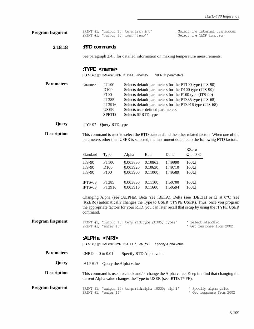
IEEE-488 Reference
3-109
PRINT #1, "output 16; temp:tran int" ' Select the internal transducerPRINT #1, "output 16; func 'temp'" ' Select the TEMP function
:RTD commands
See paragraph 2.4.5 for detailed information on making temperature measurements.
:TYPE <name>[:SENSe[1]]:TEMPerature:RTD:TYPE <name> Set RTD parameters
<name> = PT100 Selects default parameters for the PT100 type (ITS-90)D100 Selects default parameters for the D100 type (ITS-90)F100 Selects default parameters for the F100 type (ITS-90)PT385 Selects default parameters for the PT385 type (ITS-68)PT3916 Selects default parameters for the PT3916 type (ITS-68)USER Selects user-defined parameters SPRTD Selects SPRTD type
:TYPE? Query RTD type
This command is used to select the RTD standard and the other related factors. When one of theparameters other than USER is selected, the instrument defaults to the following RTD factors:
RZeroStandard Type Alpha Beta Delta Ω at 0°C
ITS-90 PT100 0.003850 0.10863 1.49990 100ΩITS-90 D100 0.003920 0.10630 1.49710 100ΩITS-90 F100 0.003900 0.11000 1.49589 100Ω
IPTS-68 PT385 0.003850 0.11100 1.50700 100ΩIPTS-68 PT3916 0.003916 0.11600 1.50594 100Ω
Changing Alpha (see :ALPHa), Beta (see :BETA), Delta (see :DELTa) or Ω at 0°C (see:RZERo) automatically changes the Type to USER (:TYPE USER). Thus, once you programthe appropriate factors for your RTD, you can later recall that setup by using the :TYPE USERcommand.
PRINT #1, "output 16; temp:rtd:type pt385; type?" ' Select standardPRINT #1, "enter 16" ' Get response from 2002
:ALPHa <NRf>[:SENSe[1]]:TEMPerature:RTD:ALPHa <NRf> Specify Alpha value
<NRf> = 0 to 0.01 Specify RTD Alpha value
:ALPHa? Query the Alpha value
This command is used to check and/or change the Alpha value. Keep in mind that changing thecurrent Alpha value changes the Type to USER (see :RTD:TYPE).
PRINT #1, "output 16; temp:rtd:alpha .0035; alph?" ' Specify alpha valuePRINT #1, "enter 16" ' Get response from 2002
Program fragment
3.18.18
Parameters
Query
Description
Program fragment
Parameters
Query
Description
Program fragment
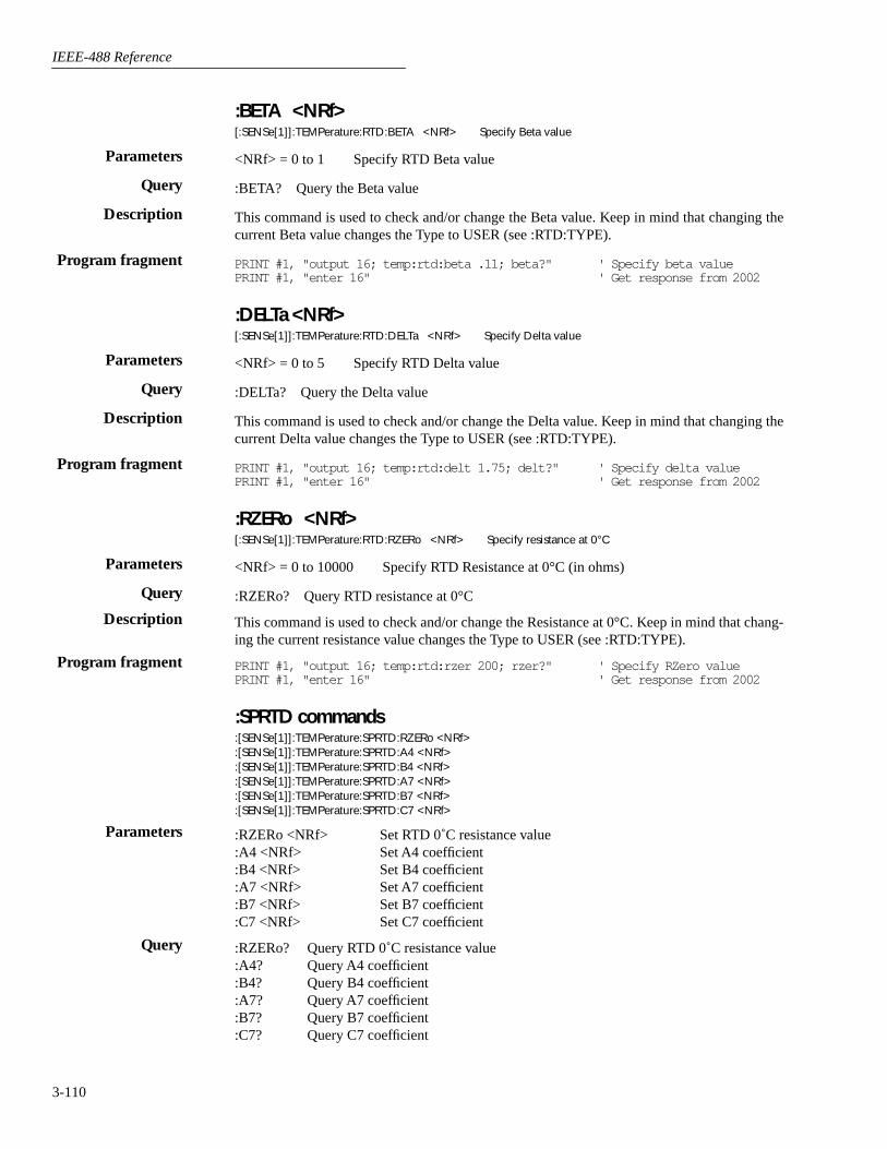
IEEE-488 Reference
3-110
:BETA <NRf>[:SENSe[1]]:TEMPerature:RTD:BETA <NRf> Specify Beta value
<NRf> = 0 to 1 Specify RTD Beta value
:BETA? Query the Beta value
This command is used to check and/or change the Beta value. Keep in mind that changing thecurrent Beta value changes the Type to USER (see :RTD:TYPE).
PRINT #1, "output 16; temp:rtd:beta .11; beta?" ' Specify beta valuePRINT #1, "enter 16" ' Get response from 2002
:DELTa <NRf>[:SENSe[1]]:TEMPerature:RTD:DELTa <NRf> Specify Delta value
<NRf> = 0 to 5 Specify RTD Delta value
:DELTa? Query the Delta value
This command is used to check and/or change the Delta value. Keep in mind that changing thecurrent Delta value changes the Type to USER (see :RTD:TYPE).
PRINT #1, "output 16; temp:rtd:delt 1.75; delt?" ' Specify delta valuePRINT #1, "enter 16" ' Get response from 2002
:RZERo <NRf>[:SENSe[1]]:TEMPerature:RTD:RZERo <NRf> Specify resistance at 0°C
<NRf> = 0 to 10000 Specify RTD Resistance at 0°C (in ohms)
:RZERo? Query RTD resistance at 0°C
This command is used to check and/or change the Resistance at 0°C. Keep in mind that chang-ing the current resistance value changes the Type to USER (see :RTD:TYPE).
PRINT #1, "output 16; temp:rtd:rzer 200; rzer?" ' Specify RZero valuePRINT #1, "enter 16" ' Get response from 2002
:SPRTD commands:[SENSe[1]]:TEMPerature:SPRTD:RZERo <NRf>:[SENSe[1]]:TEMPerature:SPRTD:A4 <NRf>:[SENSe[1]]:TEMPerature:SPRTD:B4 <NRf>:[SENSe[1]]:TEMPerature:SPRTD:A7 <NRf>:[SENSe[1]]:TEMPerature:SPRTD:B7 <NRf>:[SENSe[1]]:TEMPerature:SPRTD:C7 <NRf>
:RZERo <NRf> Set RTD 0˚C resistance value:A4 <NRf> Set A4 coefficient:B4 <NRf> Set B4 coefficient:A7 <NRf> Set A7 coefficient:B7 <NRf> Set B7 coefficient:C7 <NRf> Set C7 coefficient
:RZERo? Query RTD 0˚C resistance value:A4? Query A4 coefficient:B4? Query B4 coefficient:A7? Query A7 coefficient:B7? Query B7 coefficient:C7? Query C7 coefficient
Parameters
Query
Description
Program fragment
Parameters
Query
Description
Program fragment
Parameters
Query
Description
Program fragment
Parameters
Query
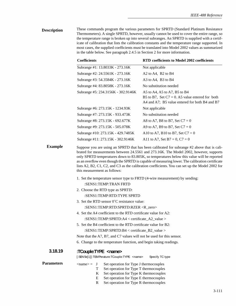
IEEE-488 Reference
3-111
These commands program the various parameters for SPRTD (Standard Platinum ResistanceThermometers). A single SPRTD, however, usually cannot be used to cover the entire range, sothe temperature range is broken up into several subranges. An SPRTD is supplied with a certif-icate of calibration that lists the calibration constants and the temperature range supported. Inmost cases, the supplied coefficients must be translated into Model 2002 values as summarizedin the table below. See paragraph 2.4.5 in Section 2 for more information.
Suppose you are using an SPRTD that has been calibrated for subrange #2 above that is cali-brated for measurements between 24.5561 and 273.16K. The Model 2002, however, supportsonly SPRTD temperatures down to 83.805K, so temperatures below this value will be reportedas an overflow even though the SPRTD is capable of measuring lower. The calibration certificatelists A2, B2, C1, C2, and C3 as the calibration coefficients. You can set up the Model 2002 forthis measurement as follows:
1. Set the temperature sensor type to FRTD (4-wire measurement) by sending:
:SENS1:TEMP:TRAN FRTD
2. Choose the RTD type as SPRTD:
:SENS1:TEMP:RTD:TYPE SPRTD
3. Set the RTD sensor 0˚C resistance value:
:SENS1:TEMP:RTD:SPRTD:RZER <R_zero>
4. Set the A4 coefficient to the RTD certificate value for A2:
:SENS1:TEMP:SPRTD:A4 < certificate_A2_value >
5. Set the B4 coefficient to the RTD certificate value for B2:
:SENS1:TEMP:SPRTD:B4 < certificate_B2_value >
Note that the A7, B7, and C7 values will not be used for this sensor.
6. Change to the temperature function, and begin taking readings.
:TCouple:TYPE <name>[:SENSe[1]]:TEMPerature:TCouple:TYPE <name> Specify TC type
<name> = J Set operation for Type J thermocouplesT Set operation for Type T thermocouplesK Set operation for Type K thermocouplesE Set operation for Type E thermocouplesR Set operation for Type R thermocouples
Coefficients RTD coefficients to Model 2002 coefficients
Subrange #1: 13.8033K - 273.16K Not applicable
Subrange #2: 24.5561K - 273.16K A2 to A4, B2 to B4
Subrange #3: 54.3584K - 273.16K A3 to A4, B3 to B4
Subrange #4: 83.8058K - 273.16K No substitution needed
Subrange #5: 234.3156K - 302.9146K A5 to A4, A5 to A7, B5 to B4B5 to B7, Set C7 = 0. A5 value entered for both A4 and A7; B5 value entered for both B4 and B7
Subrange #6: 273.15K - 1234.93K Not applicable
Subrange #7: 273.15K - 933.473K No substitution needed
Subrange #8: 273.15K - 692.677K A8 to A7, B8 to B7, Set C7 = 0
Subrange #9: 273.15K - 505.078K A9 to A7, B9 to B7, Set C7 = 0
Subrange #10: 273.15K - 429.7485K A10 to A7, B10 to B7, Set C7 = 0
Subrange #11: 273.15K - 302.9146K A11 to A7, Set B7 = 0, C7 = 0
Description
Example
3.18.19
Parameters
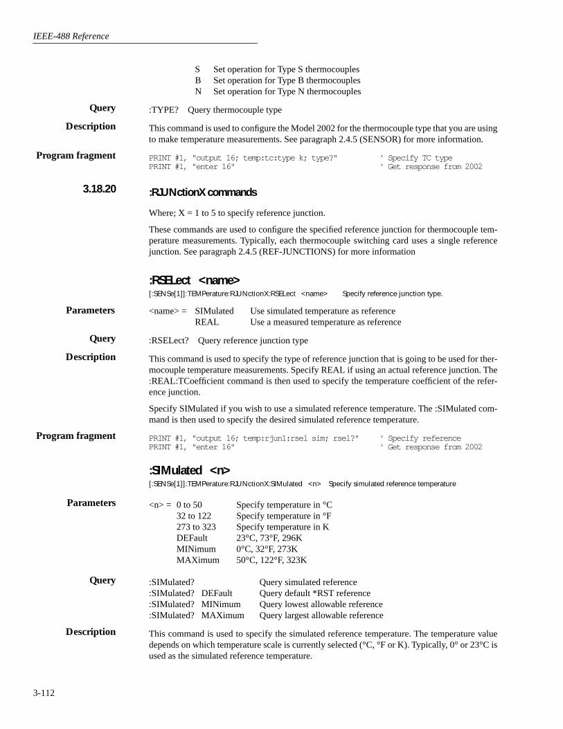
IEEE-488 Reference
3-112
S Set operation for Type S thermocouplesB Set operation for Type B thermocouplesN Set operation for Type N thermocouples
:TYPE? Query thermocouple type
This command is used to configure the Model 2002 for the thermocouple type that you are usingto make temperature measurements. See paragraph 2.4.5 (SENSOR) for more information.
PRINT #1, "output 16; temp:tc:type k; type?" ' Specify TC typePRINT #1, "enter 16" ' Get response from 2002
:RJUNctionX commands
Where; X = 1 to 5 to specify reference junction.
These commands are used to configure the specified reference junction for thermocouple tem-perature measurements. Typically, each thermocouple switching card uses a single referencejunction. See paragraph 2.4.5 (REF-JUNCTIONS) for more information
:RSELect <name>[:SENSe[1]]:TEMPerature:RJUNctionX:RSELect <name> Specify reference junction type.
<name> = SIMulated Use simulated temperature as referenceREAL Use a measured temperature as reference
:RSELect? Query reference junction type
This command is used to specify the type of reference junction that is going to be used for ther-mocouple temperature measurements. Specify REAL if using an actual reference junction. The:REAL:TCoefficient command is then used to specify the temperature coefficient of the refer-ence junction.
Specify SIMulated if you wish to use a simulated reference temperature. The :SIMulated com-mand is then used to specify the desired simulated reference temperature.
PRINT #1, "output 16; temp:rjun1:rsel sim; rsel?" ' Specify referencePRINT #1, "enter 16" ' Get response from 2002
:SIMulated <n>[:SENSe[1]]:TEMPerature:RJUNctionX:SIMulated <n> Specify simulated reference temperature
<n> = 0 to 50 Specify temperature in °C32 to 122 Specify temperature in °F273 to 323 Specify temperature in KDEFault 23°C, 73°F, 296KMINimum 0°C, 32°F, 273KMAXimum 50°C, 122°F, 323K
:SIMulated? Query simulated reference:SIMulated? DEFault Query default *RST reference:SIMulated? MINimum Query lowest allowable reference:SIMulated? MAXimum Query largest allowable reference
This command is used to specify the simulated reference temperature. The temperature valuedepends on which temperature scale is currently selected (°C, °F or K). Typically, 0° or 23°C isused as the simulated reference temperature.
Query
Description
Program fragment
3.18.20
Parameters
Query
Description
Program fragment
Parameters
Query
Description
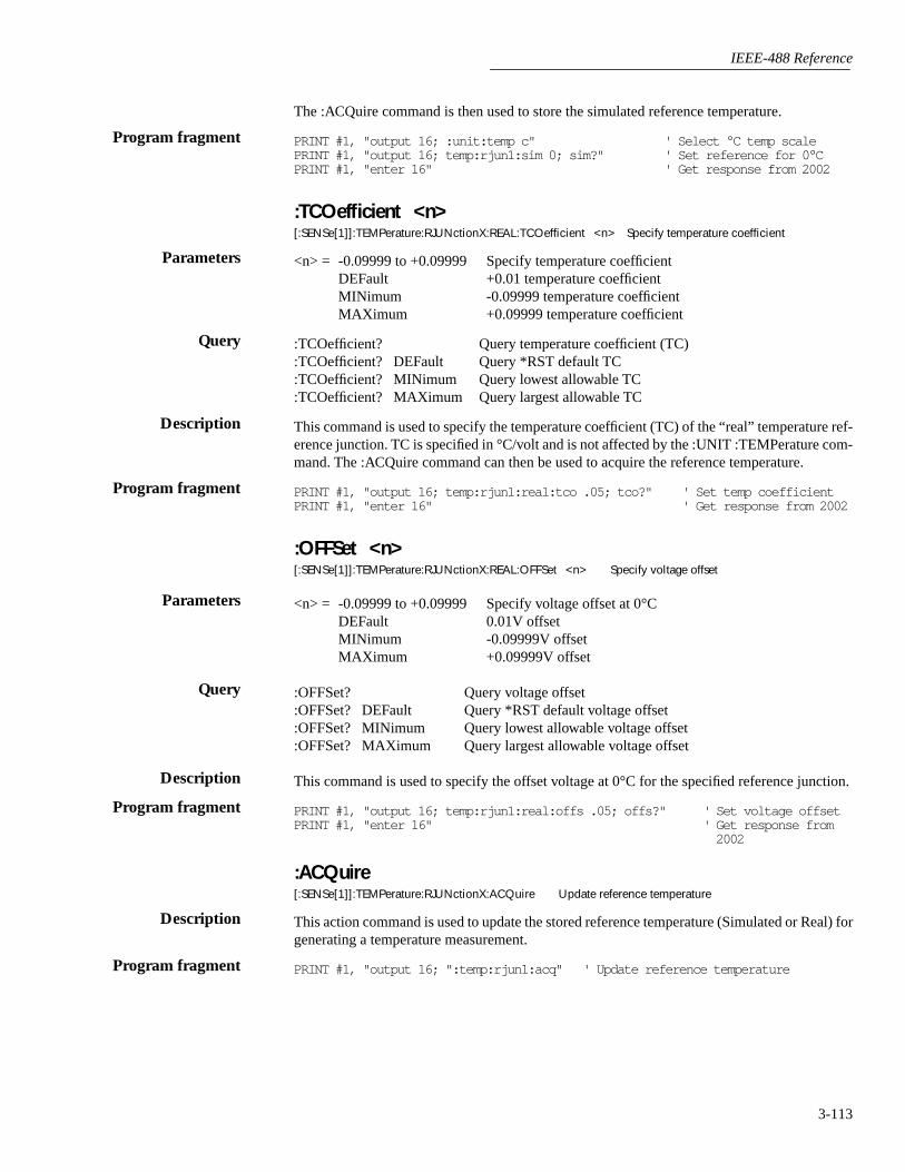
IEEE-488 Reference
3-113
The :ACQuire command is then used to store the simulated reference temperature.
PRINT #1, "output 16; :unit:temp c" ' Select °C temp scalePRINT #1, "output 16; temp:rjun1:sim 0; sim?" ' Set reference for 0°CPRINT #1, "enter 16" ' Get response from 2002
:TCOefficient <n>[:SENSe[1]]:TEMPerature:RJUNctionX:REAL:TCOefficient <n> Specify temperature coefficient
<n> = -0.09999 to +0.09999 Specify temperature coefficientDEFault +0.01 temperature coefficientMINimum -0.09999 temperature coefficientMAXimum +0.09999 temperature coefficient
:TCOefficient? Query temperature coefficient (TC):TCOefficient? DEFault Query *RST default TC:TCOefficient? MINimum Query lowest allowable TC:TCOefficient? MAXimum Query largest allowable TC
This command is used to specify the temperature coefficient (TC) of the “real” temperature ref-erence junction. TC is specified in °C/volt and is not affected by the :UNIT :TEMPerature com-mand. The :ACQuire command can then be used to acquire the reference temperature.
PRINT #1, "output 16; temp:rjun1:real:tco .05; tco?" ' Set temp coefficientPRINT #1, "enter 16" ' Get response from 2002
:OFFSet <n>[:SENSe[1]]:TEMPerature:RJUNctionX:REAL:OFFSet <n> Specify voltage offset
<n> = -0.09999 to +0.09999 Specify voltage offset at 0°CDEFault 0.01V offsetMINimum -0.09999V offsetMAXimum +0.09999V offset
:OFFSet? Query voltage offset:OFFSet? DEFault Query *RST default voltage offset:OFFSet? MINimum Query lowest allowable voltage offset:OFFSet? MAXimum Query largest allowable voltage offset
This command is used to specify the offset voltage at 0°C for the specified reference junction.
PRINT #1, "output 16; temp:rjun1:real:offs .05; offs?" ' Set voltage offsetPRINT #1, "enter 16" ' Get response from
2002
:ACQuire[:SENSe[1]]:TEMPerature:RJUNctionX:ACQuire Update reference temperature
This action command is used to update the stored reference temperature (Simulated or Real) forgenerating a temperature measurement.
PRINT #1, "output 16; ":temp:rjun1:acq" ' Update reference temperature
Program fragment
Parameters
Query
Description
Program fragment
Parameters
Query
Description
Program fragment
Description
Program fragment

IEEE-488 Reference
3-114
:OCOMpensated <b>[:SENSe[1]]:RESistance:OCOMpensated <b> Control offset compensation for Ω2[:SENSe[1]]:FRESistance:OCOMpensated <b> Control offset compensation for Ω4
<b> = 0 or OFF Disable offset compensated ohms 1 or ON Enable offset compensated ohms
:OCOMpensated? Query state of offset compensated ohms
This command is used to enable or disable the offset compensated ohms feature. Offset com-pensation is used to cancel the effects of offset voltages (such as thermal EMFs) when makingresistance measurements. Offset compensation is explained in detail in paragraph 2.4.3 (OFF-SETCOMP).
PRINT #1, "output 16; :res:ocom on; ocom?" ' Enable offset compensationPRINT #1, "enter 16" ' Get response from 2002
:DTCouple commands
The following commands are used to make differential thermocouple temperature measure-ments using the Model 1801 Nanovolt Preamp. Refer to the instruction manual for the Model1801 for details.
:TYPe <type>[:SENSe[1]]:TEMPerature:DTCouple:TYPE <type> Set thermocouple type
<type> = J Set operation for Type J thermocoupleK Set operation for Type K thermocoupleT Set operation for Type T thermocoupleE Set operation for Type E thermocoupleR Set operation for Type R thermocoupleS Set operation for Type S thermocoupleB Set operation for Type B thermocoupleN Set operation for Type N thermocoupleUSER Select user-defined slope for other type of thermocouples
:TYPe? Query DTC type
This command is used to set thermocouple type for differential thermocouple measurementsusing the Model 1801 Nanovolt Preamp. Selecting one of the seven standard thermocouples (J,K, T, E, R, S, B, or N) requires that you specify the reference temperature for the reference ther-mocouple using the :RTEMperature command.
When using other thermocouple types (USER selected), you must specify the thermocoupleslope (coefficient) using the :USLope command.
Refer to the Model 1801 Nanovolt Preamp Instruction manual for details on making differentialthermocouple temperature measurements.
PRINT #1, "output 16; :temp:dtc:type K; type?" ' Select type K TCPRINT #1, "enter 16" ' Get response from 2002
3.18.21
Parameters
Query
Description
Program fragment
3.18.22
Parameters
Query
Description
Program fragment
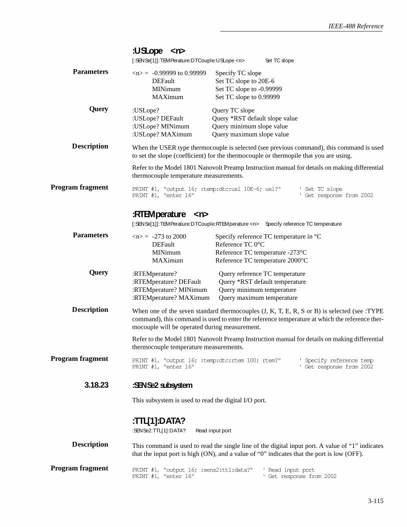
IEEE-488 Reference
3-115
:USLope <n>[:SENSe[1]]:TEMPerature:DTCouple:USLope <n> Set TC slope
<n> = -0.99999 to 0.99999 Specify TC slopeDEFault Set TC slope to 20E-6MINimum Set TC slope to -0.99999MAXimum Set TC slope to 0.99999
:USLope? Query TC slope:USLope? DEFault Query *RST default slope value:USLope? MINimum Query minimum slope value:USLope? MAXimum Query maximum slope value
When the USER type thermocouple is selected (see previous command), this command is usedto set the slope (coefficient) for the thermocouple or thermopile that you are using.
Refer to the Model 1801 Nanovolt Preamp Instruction manual for details on making differentialthermocouple temperature measurements.
PRINT #1, "output 16; :temp:dtc:usl 10E-6; usl?" ' Set TC slopePRINT #1, "enter 16" ' Get response from 2002
:RTEMperature <n>[:SENSe[1]]:TEMPerature:DTCouple:RTEMperature <n> Specify reference TC temperature
<n> = -273 to 2000 Specify reference TC temperature in °CDEFault Reference TC 0°CMINimum Reference TC temperature -273°CMAXimum Reference TC temperature 2000°C
:RTEMperature? Query reference TC temperature:RTEMperature? DEFault Query *RST default temperature:RTEMperature? MINimum Query minimum temperature:RTEMperature? MAXimum Query maximum temperature
When one of the seven standard thermocouples (J, K, T, E, R, S or B) is selected (see :TYPEcommand), this command is used to enter the reference temperature at which the reference ther-mocouple will be operated during measurement.
Refer to the Model 1801 Nanovolt Preamp Instruction manual for details on making differentialthermocouple temperature measurements.
PRINT #1, "output 16; :temp:dtc:rtem 100; rtem?" ' Specify reference tempPRINT #1, "enter 16" ' Get response from 2002
:SENSe2 subsystem
This subsystem is used to read the digital I/O port.
:TTL[1]:DATA?:SENSe2:TTL[1]:DATA? Read input port
This command is used to read the single line of the digital input port. A value of “1” indicatesthat the input port is high (ON), and a value of “0” indicates that the port is low (OFF).
PRINT #1, "output 16; :sens2:ttl:data?" ' Read input portPRINT #1, "enter 16" ' Get response from 2002
Parameters
Query
Description
Program fragment
Parameters
Query
Description
Program fragment
3.18.23
Description
Program fragment
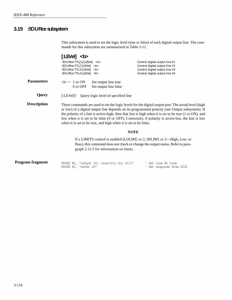
IEEE-488 Reference
3-116
3.19 :SOURce subsystem
This subsystem is used to set the logic level (true or false) of each digital output line. The com-mands for this subsystem are summarized in Table 3-11.
[:LEVel] <b>:SOURce:TTL[1]:[LEVel] <b> Control digital output line #1:SOURce:TTL2:[LEVel] <b> Control digital output line #2:SOURce:TTL3:[LEVel] <b> Control digital output line #3:SOURce:TTL4:[LEVel] <b> Control digital output line #4
<b> = 1 or ON Set output line true0 or OFF Set output line false
[:LEVel]? Query logic level of specified line
These commands are used to set the logic levels for the digital output port. The actual level (highor low) of a digital output line depends on its programmed polarity (see Output subsystem). Ifthe polarity of a line is active-high, then that line is high when it is set to be true (1 or ON), andlow when it is set to be false (0 or OFF). Conversely, if polarity is active-low, the line is lowwhen it is set to be true, and high when it is set to be false.
NOTE
If a LIMITS control is enabled (LOLIM1 or 2, HILIM1 or 2—High, Low, orPass), this command does not check or change the output status. Refer to para-graph 2.12.5 for information on limits.
PRINT #1, "output 16; :sour:ttl on; ttl?" ' Set line #1 truePRINT #1, "enter 16" ' Get response from 2002
Parameters
Query
Description
Program fragment
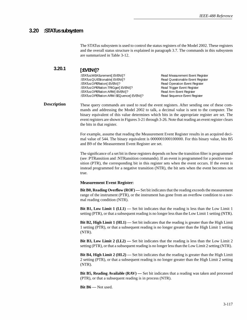
IEEE-488 Reference
3-117
3.20 :STATus subsystem
The STATus subsystem is used to control the status registers of the Model 2002. These registersand the overall status structure is explained in paragraph 3.7. The commands in this subsystemare summarized in Table 3-12.
[:EVENt]?
:STATus:MEASurement[:EVENt]? Read Measurement Event Register:STATus:QUEStionable[:EVENt]? Read Questionable Event Register:STATus:OPERation[:EVENt]? Read Operation Event Register:STATus:OPERation:TRIGger[:EVENt]? Read Trigger Event Register:STATus:OPERation:ARM[:EVENt]? Read Arm Event Register:STATus:OPERation:ARM:SEQuence[:EVENt]? Read Sequence Event Register
These query commands are used to read the event registers. After sending one of these com-mands and addressing the Model 2002 to talk, a decimal value is sent to the computer. Thebinary equivalent of this value determines which bits in the appropriate register are set. Theevent registers are shown in Figures 3-21 through 3-26. Note that reading an event register clearsthe bits in that register.
For example, assume that reading the Measurement Event Register results in an acquired deci-mal value of 544. The binary equivalent is 0000001000100000. For this binary value, bits B5and B9 of the Measurement Event Register are set.
The significance of a set bit in these registers depends on how the transition filter is programmed(see :PTRansition and :NTRansition commands). If an event is programmed for a positive tran-sition (PTR), the corresponding bit in this register sets when the event occurs. If the event isinstead programmed for a negative transition (NTR), the bit sets when the event becomes nottrue.
Measurement Event Register:
Bit B0, Reading Overflow (ROF) —
Set bit indicates that the reading exceeds the measurementrange of the instrument (PTR), or the instrument has gone from an overflow condition to a nor-mal reading condition (NTR).
Bit B1, Low Limit 1 (LL1) —
Set bit indicates that the reading is less than the Low Limit 1setting (PTR), or that a subsequent reading is no longer less than the Low Limit 1 setting (NTR).
Bit B2, High Limit 1 (HL1) —
Set bit indicates that the reading is greater than the High Limit1 setting (PTR), or that a subsequent reading is no longer greater than the High Limit 1 setting(NTR).
Bit B3, Low Limit 2 (LL2) —
Set bit indicates that the reading is less than the Low Limit 2setting (PTR), or that a subsequent reading is no longer less than the Low Limit 2 setting (NTR).
Bit B4, High Limit 2 (HL2) —
Set bit indicates that the reading is greater than the High Limit2 setting (PTR), or that a subsequent reading is no longer greater than the High Limit 2 setting(NTR).
Bit B5, Reading Available (RAV) —
Set bit indicates that a reading was taken and processed(PTR), or that a subsequent reading is in process (NTR).
Bit B6 —
Not used.
3.20.1
Description

IEEE-488 Reference
3-118
Bit B7, Buffer Available (BAV) —
Set bit indicates that there are at least two readings in thetrace buffer (PTR), or the buffer has become empty (NTR).
Bit B8, Buffer Half Full (BHF) —
Set bit indicates that the trace buffer is half full (PTR), orthat the buffer is no longer half full (NTR).
Bit B9, Buffer Full (BFL) —
Set bit indicates that the trace buffer is full (PTR), or that thebuffer is no longer full (NTR).
Bit B10 —
Not used.
Bit B11, Buffer Pretriggered (BPT) —
Set bit indicates that the trace buffer pretrigger eventhas occurred (PTR), or the operations associated with the pretrigger have been completed(NTR).
Bits B12 through B15 —
Not used.
Questionable Event Register:
Bits B0 through B3 —
Not used.
Bit B4, Temperature Summary (Temp) —
Set bit indicates that an invalid reference junctionmeasurement has occurred for thermocouple temperature measurements (PTR), or a subsequentvalid reference junction measurement has occurred (NTR).
Bits B5, B6 and B7 —
Not used.
Bit B8, Calibration Summary (Cal) —
Set bit indicates that an invalid calibration constant wasdetected during the power-up sequence (PTR). The instrument will instead use a default calibra-tion constant. This error will clear after successful calibration of the instrument.
Bits B9 through B13 —
Not used.
Figure 3-21Measurement Event Register
RAV
B15 - B12 B10 B9 B8 B7 B6 B5 B4 B3 B2 B1 B0
(2 )9 (2 )8 (2 )7 (2 )5 (2 )4 (2 )3 (2 )2 (2 )1 (2 )0
32
0/1
Bit Position
Event
Decimal Weighting
Value
Value : 1 = Measurement Event Set 0 = Measurement Event Cleared
LL1
2
0/1
Events : BPT = Buffer Pretriggered BFL = Buffer Full BHF = Buffer Half Full BAV = Buffer Available RAV = Reading Available HL2 = High Limit 2 LL2 = Low Limit 2 HL1 = High Limit 1 LL1 = Low Limit 1 ROF = Reading Overflow
BFL HL2 HL1 ROF
512 16 4 1
0/1 0/1 0/1 0/1
BHF BAV LL2
256 128 8
0/1 0/1 0/1
BPT
B11
(2 )11
2048
0/1
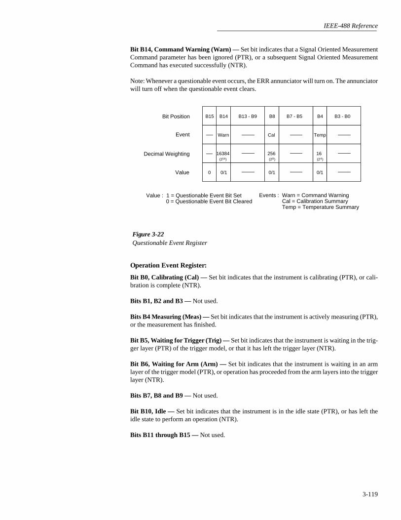
IEEE-488 Reference
3-119
Bit B14, Command Warning (Warn) —
Set bit indicates that a Signal Oriented MeasurementCommand parameter has been ignored (PTR), or a subsequent Signal Oriented MeasurementCommand has executed successfully (NTR).
Note: Whenever a questionable event occurs, the ERR annunciator will turn on. The annunciatorwill turn off when the questionable event clears.
Operation Event Register:
Bit B0, Calibrating (Cal) —
Set bit indicates that the instrument is calibrating (PTR), or cali-bration is complete (NTR).
Bits B1, B2 and B3 —
Not used.
Bits B4 Measuring (Meas) —
Set bit indicates that the instrument is actively measuring (PTR),or the measurement has finished.
Bit B5, Waiting for Trigger (Trig) —
Set bit indicates that the instrument is waiting in the trig-ger layer (PTR) of the trigger model, or that it has left the trigger layer (NTR).
Bit B6, Waiting for Arm (Arm) —
Set bit indicates that the instrument is waiting in an armlayer of the trigger model (PTR), or operation has proceeded from the arm layers into the triggerlayer (NTR).
Bits B7, B8 and B9 —
Not used.
Bit B10, Idle —
Set bit indicates that the instrument is in the idle state (PTR), or has left theidle state to perform an operation (NTR).
Bits B11 through B15 —
Not used.
Cal
B13 - B9 B8B15 B14
(2 )8
256(2 )14
16384
0/10/1
Warn
B7 - B5
0
Temp
B4
(2 )4
16
0/1
B3 - B0Bit Position
Event
Decimal Weighting
Value
Events : Warn = Command Warning Cal = Calibration Summary Temp = Temperature Summary
Value : 1 = Questionable Event Bit Set 0 = Questionable Event Bit Cleared
Figure 3-22Questionable Event Register

IEEE-488 Reference
3-120
Trigger Event Register:
Bit B0 —
Not used.
Bit B1, Sequence 1 (Seq1) —
Set bit indicates that the instrument is in the trigger layer (PTR),or that the instrument has exited from the trigger layer (NTR).
Bits B2 through B15 —
Not used.
Arm Event Register:
Bit B0 —
Not used.
Figure 3-23Operation Event Register
Idle Arm Trig
B15 - B11 B10 B9 B8 B7 B6 B5 B4 B3 B2 B1 B0
(2 )10
1024(2 )6 (2 )5 (2 )0
64 32
0/1 0/1 0/1
Bit Position
Event
Decimal Weighting
Value
Value : 1 = Operation Event Set 0 = Operation Event Cleared
Events : Idle = Idle state of the 2002 Arm = Waiting for Arm Trig = Waiting for Trigger Meas = Measuring Cal = Calibrating
Cal
1
0/1
Meas
(2 )4
16
0/1
Figure 3-24Trigger Event Register
B15 - B2 B1 B0
(2 )12
0/1
Bit Position
Event
Decimal Weighting
Value
Value : 1 = Event Bit Set 0 = Event Bit Cleared
Event : Seq1 = Sequence 1
Seq1

IEEE-488 Reference
3-121
Bit B1, Sequence 1 (Seq1) —
Set bit indicates that the instrument is in an arm layer (PTR), orthat the instrument has exited from the arm layers (NTR).
Bits B2 through B15 —
Not used.
Sequence Event Register:
Bit B0 —
Not used.
Bit B1, Layer 1 (Lay1) —
Set bit indicates that instrument operation is in arm layer 1 (PTR),or that operation has exited from arm layer 1 NTR).
Bit B2, Layer 2 (Lay2) —
Set bit indicates that instrument operation is in arm layer 2 (PTR),or that operation has exited from arm layer 2 NTR).
Bits B3 through B15 —
Not used.
PRINT #1, "output 16; :stat:meas?" ' Query Measure Event RegisterPRINT #1, "enter 16" ' Get response from 2002
Figure 3-25Arm Event Register
B15 - B2 B1 B0
(2 )12
0/1
Bit Position
Event
Decimal Weighting
Value
Value : 1 = Event Bit Set 0 = Event Bit Cleared
Seq1
Event : Seq1 = Sequence 1
Program fragment
Figure 3-26Sequence Event Register
Lay2
B15 - B3 B2 B1 B0
(2 )2
4(2 )1
2
0/1 0/1
Bit Position
Event
Decimal Weighting
Value
Value : 1 = Event Bit Set 0 = Event Bit Cleared
Event : Lay1 = Layer 1 Lay2 = Layer 2
Lay1

IEEE-488 Reference
3-122
:ENABle <NRf>
:STATus:MEASurement:ENABle <NRf> Program Measurement Event Enable Register:STATus:QUEStionable:ENABle <NRf> Program Questionable Event Enable Register:STATus:OPERation:ENABle <NRf> Program Operation Event Enable Register:STATus:OPERation:TRIGger:ENABle <NRf> Program Trigger Event Enable Register:STATus:OPERation:ARM:ENABle <NRf> Program Arm Event Enable Register:STATus:OPERation:ARM:SEQuence:ENABle <NRf> Program Sequence Event Enable Register
<NRf> = 0 Clear register <NRf> = 128 Set bit B71 Set bit B0 256 Set bit B82 Set bit B1 512 Set bit B94 Set bit B2 1024 Set bit B108 Set bit B3 2048 Set bit B1116 Set bit B4 16384 Set bit B1432 Set bit B5 65535 Set all bits64 Set bit B6
:ENABle? Query enable register
These commands are used to set the contents of the event enable registers (see Figures 3-27through 3-32). An :ENABle command is sent with the decimal equivalent of the binary valuethat determines the desired state (0 or 1) of each bit in the appropriate register.
Each event enable register is used as a mask for events (see [:EVENt] for descriptions of events).When a bit in an event enable register is cleared (0), the corresponding bit in the event registeris masked and thus, cannot set the corresponding summary bit of the next register set in the sta-tus structure. Conversely, when a bit in an event enable register is set (1), the corresponding bitin the event register is unmasked. When the unmasked bit in the event register sets, the summarybit of the next register set in the status structure will set.
The decimal weighting of the bits for each event enable register are included in Figures 3-27through 3-32. The sum of the decimal weights of the bits that you wish to set is sent as theparameter (<NRf>) for the appropriate :ENABle command. For example, to set the BFL andRAV bits of the Measurement Event Enable Register, send the following command:
:stat:meas:enab 544
where; BFL (bit B9) = Decimal = 512RAV (bit B5) = Decimal = 32
<NRf> = = 544
PRINT #1, "output 16; :stat:oper:enab 514; enab?" ' Set B1 and B9 of Op EnableRegister and query
PRINT #1, "enter 16" ' Get response message from2002
3.20.2
Parameters
Query
Description
Program fragment

IEEE-488 Reference
3-123
Figure 3-27Measurement Event Enable Register
RAV
B15 - B12 B10 B9 B8 B7 B6 B5 B4 B3 B2 B1 B0
(2 )9 (2 )8 (2 )7 (2 )5 (2 )4 (2 )3 (2 )2 (2 )1 (2 )0
32
0/1
Bit Position
Event
Decimal Weighting
Value
Value : 1 = Enable Measurement Event 0 = Disable (Mask) Measurement Event
LL1
2
0/1
Events : BPT = Buffer Pretriggered BFL = Buffer Full BHF = Buffer Half Full BAV = Buffer Available RAV = Reading Available HL2 = High Limit 2 LL2 = Low Limit 2 HL1 = High Limit 1 LL1 = Low Limit 1 ROF = Reading Overflow
BFL HL2 HL1 ROF
512 16 4 1
0/1 0/1 0/1 0/1
BHF BAV LL2
256 128 8
0/1 0/1 0/1
BPT
B11
(2 )11
2048
0/1
Figure 3-28Questionable Event Enable Register
Bit Position
Event
Decimal Weighting
Value
Value : 1 = Enable Questionable Event 0 = Disable (Mask) Questionable Event
Events : Warn = Command Warning Cal = Calibration Summary Temp = Temperature Summary
Cal
B13 - B9 B8B15 B14
(2 )8
256(2 )14
16384
0/10/1
Warn
B7 - B5
0
Temp
B4
(2 )4
16
0/1
B3 - B0
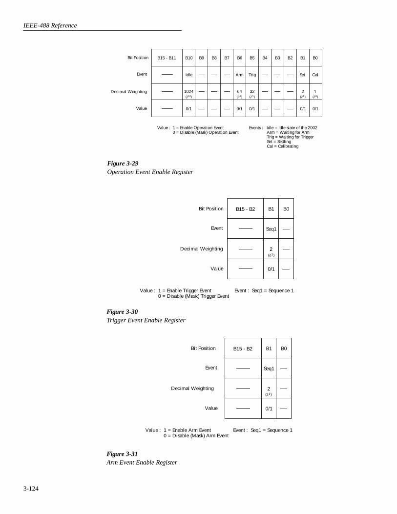
IEEE-488 Reference
3-124
Figure 3-29Operation Event Enable Register
Idle Arm Trig
B15 - B11 B10 B9 B8 B7 B6 B5 B4 B3 B2 B1 B0
(2 )10
1024(2 )6 (2 )5 (2 )1 (2 )0
64 32
0/1 0/1 0/1
Bit Position
Event
Decimal Weighting
Value
Value : 1 = Enable Operation Event 0 = Disable (Mask) Operation Event
Set
2
0/1
Events : Idle = Idle state of the 2002 Arm = Waiting for Arm Trig = Waiting for Trigger Set = Settling Cal = Calibrating
Cal
1
0/1
Figure 3-30Trigger Event Enable Register
B15 - B2 B1 B0
(2 )1
2
0/1
Bit Position
Event
Decimal Weighting
Value
Value : 1 = Enable Trigger Event 0 = Disable (Mask) Trigger Event
Event : Seq1 = Sequence 1
Seq1
Figure 3-31Arm Event Enable Register
B15 - B2 B1 B0
(2 )12
0/1
Bit Position
Event
Decimal Weighting
Value
Value : 1 = Enable Arm Event 0 = Disable (Mask) Arm Event
Seq1
Event : Seq1 = Sequence 1
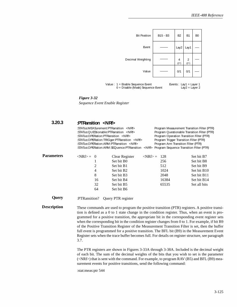
IEEE-488 Reference
3-125
:PTRansition <NRf>
:STATus:MEASurement:PTRansition <NRf> Program Measurement Transition Filter (PTR):STATus:QUEStionable:PTRansition <NRf> Program Questionable Transition Filter (PTR):STATus:OPERation:PTRansition <NRf> Program Operation Transition Filter (PTR):STATus:OPERation:TRIGger:PTRansition <NRf> Program Trigger Transition Filter (PTR):STATus:OPERation:ARM:PTRansition <NRf> Program Arm Transition Filter (PTR):STATus:OPERation:ARM:SEQuence:PTRansition <NRf> Program Sequence Transition Filter (PTR)
<NRf> = 0 Clear Register <NRf> = 128 Set bit B71 Set bit B0 256 Set bit B82 Set bit B1 512 Set bit B94 Set bit B2 1024 Set bit B108 Set bit B3 2048 Set bit B1116 Set bit B4 16384 Set bit B1432 Set bit B5 65535 Set all bits64 Set bit B6
:PTRansition? Query PTR register
These commands are used to program the positive transition (PTR) registers. A positive transi-tion is defined as a 0 to 1 state change in the condition register. Thus, when an event is pro-grammed for a positive transition, the appropriate bit in the corresponding event register setswhen the corresponding bit in the condition register changes from 0 to 1. For example, if bit B9of the Positive Transition Register of the Measurement Transition Filter is set, then the bufferfull event is programmed for a positive transition. The BFL bit (B9) in the Measurement EventRegister sets when the trace buffer becomes full. For details on register structure, see paragraph3.7.
The PTR registers are shown in Figures 3-33A through 3-38A. Included is the decimal weightof each bit. The sum of the decimal weights of the bits that you wish to set is the parameter(<NRf>) that is sent with the command. For example, to program RAV (B5) and BFL (B9) mea-surement events for positive transitions, send the following command:
:stat:meas:ptr 544
Figure 3-32Sequence Event Enable Register
Lay2
B15 - B3 B2 B1 B0
(2 )2
4(2 )1
2
0/1 0/1
Bit Position
Event
Decimal Weighting
Value
Value : 1 = Enable Sequence Event 0 = Disable (Mask) Sequence Event
Events : Lay1 = Layer 1 Lay2 = Layer 2
Lay1
3.20.3
Parameters
Query
Description

IEEE-488 Reference
3-126
where; BFL (bit B9) = 512RAV (bit B5) = 32
<NRf> = 544
Effects of positive transitions on the Measurement Event Register:
Positive transition effect onMeasurement event Measurement Event Register
Reading overflow Sets B0 when reading exceeds range limits.Low limit 1 Sets B1 when reading is less than the low limit 1 setting.High limit 1 Sets B2 when reading is greater than the low limit 1 setting.Low limit 2 Sets B3 when reading is less than the low limit 2 setting.High limit 2 Sets B4 when reading is greater than the high limit 2 setting.Reading available Sets B5 after a reading is taken and processed.Buffer available Sets B7 when the trace buffer has at least two readings.Buffer half full Sets B8 when the trace buffer becomes half full.Buffer full Sets B9 when the trace buffer becomes full.Buffer pretriggered Sets B11 when the trace buffer pretrigger event occurs.
Figure 3-33Measurement Transition Filter
RAV
B15 - B12 B10 B9 B8 B7 B6 B5 B4 B3 B2 B1 B0
(2 )9 (2 )8 (2 )7 (2 )5 (2 )4 (2 )3 (2 )2 (2 )1 (2 )0
32
0/1
Bit Position
Event
Decimal Weighting
Value
Value : 1 = Enable Positive Transition 0 = Disable Positive Transition
LL1
2
0/1
BFL HL2 HL1 ROF
512 16 4 1
0/1 0/1 0/1 0/1
BHF BAV LL2
256 128 8
0/1 0/1 0/1
A) Positive Transition (PTR) Register
RAV
B15 - B12 B10 B9 B8 B7 B6 B5 B4 B3 B2 B1 B0
(2 )9 (2 )8 (2 )7 (2 )5 (2 )4 (2 )3 (2 )2 (2 )1 (2 )0
32
0/1
Bit Position
Event
Decimal Weighting
Value
Value : 1 = Enable Negative Transition 0 = Disable Negative Transition
LL1
2
0/1
BFL HL2 HL1 ROF
512 16 4 1
0/1 0/1 0/1 0/1
BHF BAV LL2
256 128 8
0/1 0/1 0/1
B) Negative Transition (NTR) Register
BPT
B11
(2 )11
2048
0/1
BPT
B11
(2 )11
2048
0/1
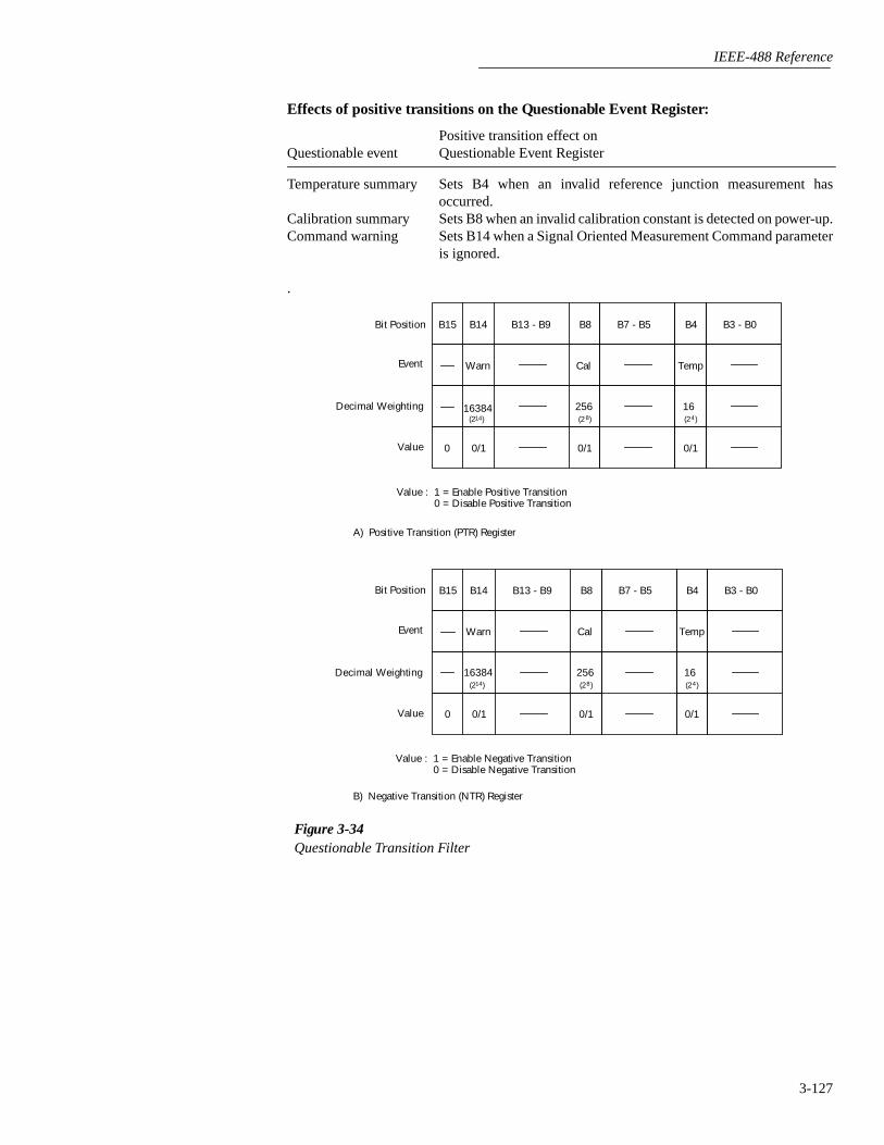
IEEE-488 Reference
3-127
Effects of positive transitions on the Questionable Event Register:
Positive transition effect onQuestionable event Questionable Event Register
Temperature summary Sets B4 when an invalid reference junction measurement hasoccurred.
Calibration summary Sets B8 when an invalid calibration constant is detected on power-up.Command warning Sets B14 when a Signal Oriented Measurement Command parameter
is ignored.
.
Figure 3-34Questionable Transition Filter
Bit Position
Event
Decimal Weighting
Value
Value : 1 = Enable Positive Transition 0 = Disable Positive Transition
A) Positive Transition (PTR) Register
Bit Position
Event
Decimal Weighting
Value
Value : 1 = Enable Negative Transition 0 = Disable Negative Transition
B) Negative Transition (NTR) Register
Cal
B13 - B9 B8B15 B14
(2 )8
256(2 )14
16384
0/10/1
Warn
B7 - B5
0
Temp
B4
(2 )4
16
0/1
B3 - B0
Cal
B13 - B9 B8B15 B14
(2 )8
256(2 )14
16384
0/10/1
Warn
B7 - B5
0
Temp
B4
(2 )4
16
0/1
B3 - B0

IEEE-488 Reference
3-128
Effects of positive transitions on the Operation Event Register:
Positive transition effect onOperation event Operation Event Register
Calibrating Sets B0 at the start of calibration.Measuring Sets B4 at the start of a measurement.Trigger layer Sets B5 when waiting in the Trigger Layer.Arm layer Sets B6 when waiting in an arm layer.Idle Sets B10 when entering the idle state.
.
Figure 3-35Operation Transition Filter
Idle Arm Trig
B15 - B11 B10 B9 B8 B7 B6 B5 B4 B3 B2 B1 B0
(2 )10
1024(2 )6 (2 )5 (2 )1 (2 )0
64 32
0/1 0/1 0/1
Bit Position
Event
Decimal Weighting
Value
Value : 1 = Enable Positive Transition 0 = Disable Positive Transition
A) Positive Transition (PTR) Register
Idle Arm Trig
B15 - B11 B10 B9 B8 B7 B6 B5 B4 B3 B2 B1 B0
(2 )10
1024(2 )6 (2 )5 (2 )1 (2 )0
64 32
0/1 0/1 0/1
Bit Position
Event
Decimal Weighting
Value
Value : 1 = Enable Negative Transition 0 = Disable Negative Transition
B) Negative Transition (NTR) Register
Set
2
0/1
Set
2
0/1
Cal
1
0/1
Cal
1
0/1

IEEE-488 Reference
3-129
Effects of positive transitions on the Trigger Event Register:
Positive transition effect onTrigger event Trigger Event Register
Sequence 1 Sets B1 when waiting in Trigger Layer.
.
Figure 3-36Trigger Transition Filter
B15 - B2 B1 B0
(2 )1
2
0/1
Bit Position
Event
Decimal Weighting
Value
Value : 1 = Enable Positive Transition 0 = Disable Positive Transition
A) Positive Transition (PTR) Register
Seq1
B15 - B2 B1 B0
0/1
Bit Position
Event
Decimal Weighting
Value
Value : 1 = Enable Negative Transition 0 = Disable Negative Transition
B) Negative Transition (NTR) Register
Seq1
(2 )1
2
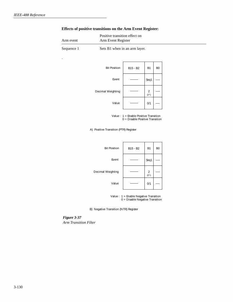
IEEE-488 Reference
3-130
Effects of positive transitions on the Arm Event Register:
Positive transition effect onArm event Arm Event Register
Sequence 1 Sets B1 when in an arm layer.
.
Figure 3-37Arm Transition Filter
B15 - B2 B1 B0
(2 )1
2
0/1
Bit Position
Event
Decimal Weighting
Value
Value : 1 = Enable Positive Transition 0 = Disable Positive Transition
Seq1
A) Positive Transition (PTR) Register
B15 - B2 B1 B0
(2 )1
2
0/1
Bit Position
Event
Decimal Weighting
Value
Value : 1 = Enable Negative Transition 0 = Disable Negative Transition
Seq1
B) Negative Transition (NTR) Register

IEEE-488 Reference
3-131
Effects of positive transitions on the Sequence Event Register:
Positive transition effect onSequence event Sequence Event Register
Layer 1 Sets B1 when in Arm Layer 1.Layer 2 Sets B2 when in Arm Layer 2.
.
PRINT #1, "output 16; :stat:oper:ptr 1026; ptr?" ' Set B1 and B10 of OperationPTR
PRINT #1, "enter 16" ' Get response message from2002
Figure 3-38Sequence Transition Filter
Lay2
B15 - B3 B2 B1 B0
(2 )2
4(2 )1
2
0/1 0/1
Bit Position
Event
Decimal Weighting
Value
Value : 1 = Enable Positive Transition 0 = Disable Positive Transition
Lay1
A) Positive Transition (PTR) Register
Lay2
B15 - B3 B2 B1 B0
(2 )2
4(2 )1
2
0/1 0/1
Bit Position
Event
Decimal Weighting
Value
Value : 1 = Enable Negative Transition 0 = Disable Negative Transition
Lay1
B) Negative Transition (NTR) Register
Program fragment

IEEE-488 Reference
3-132
:NTRansition <NRf>
:STATus:MEASurement:NTRansition <NRf> Program Measurement Transition Filter (NTR).:STATus:QUEStionable:NTRansition <NRf> Program Questionable Transition Filter (NTR).:STATus:OPERation:NTRansition <NRf> Program Operation Transition Filter (NTR).:STATus:OPERation:TRIGger:NTRansition <NRf> Program Trigger Transition Filter (NTR).:STATus:OPERation:ARM:NTRansition <NRf> Program Arm Transition Filter (NTR).:STATus:OPERation:ARM:SEQuence:NTRansition <NRf> Program Sequence Transition Filter (NTR).
<NRf> = 0 Clear NTR register <NRf> = 128 Set bit B7 of NTR register1 Set bit B0 of NTR register 256 Set bit B8 of NTR register2 Set bit B1 of NTR register 512 Set bit B9 of NTR register4 Set bit B2 of NTR register 1024 Set bit B10 of NTR register8 Set bit B3 of NTR register 2048 Set bit B11 of NTR register16 Set bit B4 of NTR register 16384 Set bit B14 of NTR register32 Set bit B5 of NTR register 65535 Set all bits64 Set bit B6 of NTR register
:NTRansition? Query NTR register
These commands are used to program the negative transition (NTR) registers. A negative tran-sition is defined as a 1 to 0 state change in the condition register. Thus, when an event is pro-grammed for a negative transition, the appropriate bit in the corresponding event register setswhen the corresponding bit in the condition register changes from 1 to 0. For example, if bit B9of the Negative Transition Register of the Measurement Transition Filter is set, then the bufferfull event is programmed for a negative transition. The BFL bit (B9) in the Measurement EventRegister sets when the trace buffer is no longer full. For details on register structure, see para-graph 3.7.
The NTR registers are shown in Figures 3-33B through 3-38B. Included is the decimal weightof each bit. The sum of the decimal weights of the bits that you wish to set is the parameter(<NRf>) that is sent with the command. For example, to program RAV (B5) and BFL (B9) mea-surement events for negative transitions, send the following command:
:stat:meas:ntr 544
where; BFL (bit B9) = Decimal = 512RAV (bit B5) = Decimal = 32
<NRf> = = 544
Effects of negative transitions on the Measurement Event Register:
Negative transition effect onMeasurement event Measurement Event Register
Reading overflow Sets B0 when a reading has gone from overflow to normal.Low limit 1 Sets B1 when the reading is no longer less than the low limit 1 setting.High limit 1 Sets B2 when the reading is no longer greater than the low limit 1
setting.Low limit 2 Sets B3 when the reading is no longer less than the low limit 2 setting.High limit 2 Sets B4 when the reading is no longer greater than the high limit 2
setting.Reading available Sets B5 when the next reading is being taken.Buffer available Sets B7 when the trace buffer has become empty.Buffer half full Sets B8 when the trace buffer is no longer half full.Buffer full Sets B9 when the trace buffer is no longer full.Buffer pretriggered Sets when the trace buffer pretrigger operations are completed.
3.20.4
Parameters
Query
Description
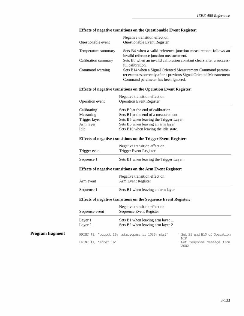
IEEE-488 Reference
3-133
Effects of negative transitions on the Questionable Event Register:
Negative transition effect onQuestionable event Questionable Event Register
Temperature summary Sets B4 when a valid reference junction measurement follows aninvalid reference junction measurement.
Calibration summary Sets B8 when an invalid calibration constant clears after a success-ful calibration.
Command warning Sets B14 when a Signal Oriented Measurement Command parame-ter executes correctly after a previous Signal Oriented MeasurementCommand parameter has been ignored.
Effects of negative transitions on the Operation Event Register:
Negative transition effect onOperation event Operation Event Register
Calibrating Sets B0 at the end of calibration.Measuring Sets B1 at the end of a measurement.Trigger layer Sets B5 when leaving the Trigger Layer.Arm layer Sets B6 when leaving an arm layer.Idle Sets B10 when leaving the idle state.
Effects of negative transitions on the Trigger Event Register:
Negative transition effect onTrigger event Trigger Event Register
Sequence 1 Sets B1 when leaving the Trigger Layer.
Effects of negative transitions on the Arm Event Register:
Negative transition effect onArm event Arm Event Register
Sequence 1 Sets B1 when leaving an arm layer.
Effects of negative transitions on the Sequence Event Register:
Negative transition effect onSequence event Sequence Event Register
Layer 1 Sets B1 when leaving arm layer 1.Layer 2 Sets B2 when leaving arm layer 2.
PRINT #1, "output 16; :stat:oper:ntr 1026; ntr?" ' Set B1 and B10 of OperationNTR
PRINT #1, "enter 16" ' Get response message from2002
Program fragment
IEEE-488 Reference
3-134
:CONDition?:STATus:MEASurement:CONDition? Read Measurement Condition Register:STATus:QUEStionable:CONDition? Read Questionable Condition Register:STATus:OPERation:CONDition? Read Operation Condition Register:STATus:OPERation:TRIGger:CONDition? Read Trigger Condition Register:STATus:OPERation:ARM:CONDition? Read Arm Condition Register:STATus:OPERation:ARM:SEQuence:CONDition? Read Sequence Condition Register
These query commands are used to read the contents of the condition registers. Each set of eventregisters (except the Standard Event register set) has a condition register. A condition register issimilar to its corresponding event register, except that it is a real-time register that constantlyupdates to reflect the current operating status of the instrument.
See [:EVENt] for register bit descriptions. Note from the status structure (paragraph 3.7) thatthe condition registers precede the transition filters. Thus, only the PTR descriptions apply tothe condition registers.
After sending one of these commands and addressing the Model 2002 to talk, a decimal valueis sent to the computer. The binary equivalent of this decimal value indicates which bits in theregister are set.
For example, if sending :stat:meas:cond? returns a decimal value of 512 (binary0000001000000000), bit B9 of the Measurement Condition Register is set indicating that thetrace buffer is full.
PRINT #1, "output 16; :stat:oper:cond?" ' Query Op Condition RegisterPRINT #1, "enter 16" ' Get response message from 2002
:PRESET:STATUS:PRESET Return registers to default conditions
When this command is sent, the SCPI event registers are affected as follows:
1. All bits of the positive transition filter registers are set to one (1).
2. All bits of the negative transition filter registers are cleared to zero (0).
3. All bits of the following registers are cleared to zero (0):
A. Operation Event Enable Register.
B. Questionable Event Enable Register.
C. Measurement Event Enable Register.
4. All bits of the following registers are set to one (1):
A. Trigger Event Enable Register.
B. Arm Event Enable Register.
C. Sequence Event Enable Register.
Note: Registers not included in the above list are not affected by this command.
PRINT #1, "output 16; :stat:pres" ' Return registers to defaults
3.20.5
Description
Program fragment
3.20.6
Description
Program fragment

IEEE-488 Reference
3-135
:QUEue commands
[:NEXT]?:STATus:QUEue[:NEXT]? Read Error Queue
As error and status messages occur, they are placed into the Error Queue. This query commandis used to read those messages.
The Error Queue is a first-in, first-out (FIFO) register. Every time you read the queue, the “old-est” message is read and that message is then removed from the queue. The queue will hold upto 10 messages. If the queue becomes full, the message “350, ‘Queue Overflow’” will occupythe last memory location in the register. On power-up, the Error Queue is empty. When the ErrorQueue is empty, the message “0, ‘No error’” is placed in the Error Queue.
The messages in the queue are preceded by a number. Negative (-) numbers are used for SCPIdefined messages, and positive (+) numbers are used for Keithley defined messages. The mes-sages are listed in Table 2-4.
After this command is sent and the Model 2002 is addressed to talk, the “oldest” message in thequeue is sent to the computer.
Note: The :STATus:QUEue[:NEXT]? query command performs the same function as the:SYSTem:ERRor? query command (see System subsystem).
PRINT #1, "output 16; :stat:que?" ' Query "oldest" message in queuePRINT #1, "enter 16" ' Get response message from 2002
ENABle <list>:STATus:QUEue:ENABle <list> Enable messages for Error Queue
<list> = (numlist)
where; numlist is a specified list of messages that you wish to enable for the Error Queue.
:ENABle? Query list of enabled messages
On power-up, all error messages are enabled and will go into the Error Queue as they occur.Status messages are not enabled and will not go into the queue. This command is used to specifywhich messages you want enabled. Messages not specified will be disabled and prevented fromentering the queue.
When this command is sent, all messages will first be disabled, then the messages specified inthe list will be enabled. Thus, the returned list (:ENABle?) will contain all the enabledmessages.
Messages are specified by numbers (see Table 2-4). The following examples show various formsfor expressing a message numlist:
Numlist = -110 Single message.-110, -140, -222 Messages separated by commas.-110:-222 Range of messages (-100 through -222).-110:-222, -230 Range entry and single entry separated by a comma.
3.20.7
Description
Program fragment
Parameters
Query
Description
IEEE-488 Reference
3-136
Note: To disable all messages from entering the Error Queue, send the following command:
:stat:que:enab ()
PRINT #1, "output 16; :stat:que:enab (0:999); enab?" ' Enable all messagesand query
PRINT #1, "enter 16" ' Get response messagefrom 2002
DISable <list>:STATus:QUEue:DISable <list> Disable messages for Error Queue
<list> = (numlist)
where; numlist is a specified list of messages that you wish to disable for the Error Queue.
:DISable? Query list of disabled messages
On power-up, all error messages are enabled and will go into the Error Queue as they occur. Sta-tus messages are not enabled and will not go into the queue. This command is used to specifywhich messages you want disabled. Disabled messages are prevented from going into the ErrorQueue.
Messages are specified by numbers (see Table 2-4). See :QUEue:ENABle for examples to ex-press a numlist.
PRINT #1, "output 16; :stat:que:dis (-140:-150); dis?" ' Disable messagesand query
PRINT #1, "enter 16" ' Get response mes-sage from 2002
:CLEar:STATus:QUEue:CLEar Clear Error Queue
This action command is used to clear the Error Queue of messages.
PRINT #1, "output 16; :stat:que:cle" ' Clear Error Queue
Program fragment
Parameters
Query
Description
Program fragment
Description
Program fragment
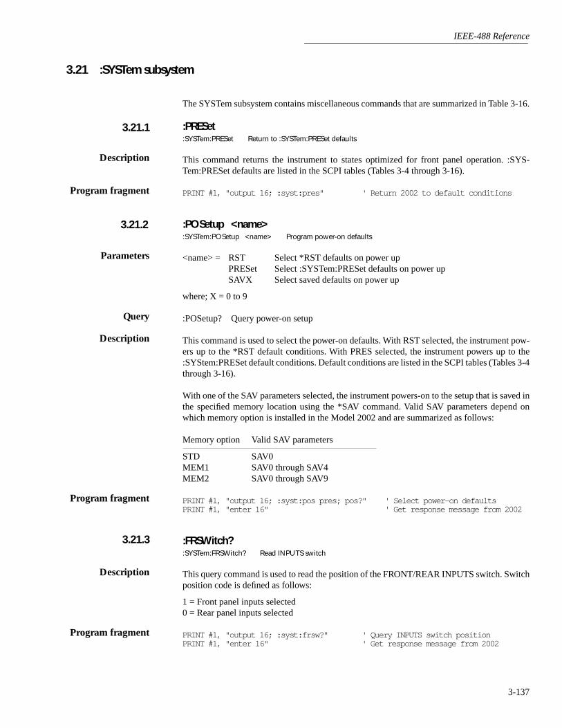
IEEE-488 Reference
3-137
3.21 :SYSTem subsystem
The SYSTem subsystem contains miscellaneous commands that are summarized in Table 3-16.
:PRESet:SYSTem:PRESet Return to :SYSTem:PRESet defaults
This command returns the instrument to states optimized for front panel operation. :SYS-Tem:PRESet defaults are listed in the SCPI tables (Tables 3-4 through 3-16).
PRINT #1, "output 16; :syst:pres" ' Return 2002 to default conditions
:POSetup <name>:SYSTem:POSetup <name> Program power-on defaults
<name> = RST Select *RST defaults on power upPRESet Select :SYSTem:PRESet defaults on power upSAVX Select saved defaults on power up
where; X = 0 to 9
:POSetup? Query power-on setup
This command is used to select the power-on defaults. With RST selected, the instrument pow-ers up to the *RST default conditions. With PRES selected, the instrument powers up to the:SYStem:PRESet default conditions. Default conditions are listed in the SCPI tables (Tables 3-4through 3-16).
With one of the SAV parameters selected, the instrument powers-on to the setup that is saved inthe specified memory location using the *SAV command. Valid SAV parameters depend onwhich memory option is installed in the Model 2002 and are summarized as follows:
Memory option Valid SAV parameters
STD SAV0MEM1 SAV0 through SAV4MEM2 SAV0 through SAV9
PRINT #1, "output 16; :syst:pos pres; pos?" ' Select power-on defaultsPRINT #1, "enter 16" ' Get response message from 2002
:FRSWitch?:SYSTem:FRSWitch? Read INPUTS switch
This query command is used to read the position of the FRONT/REAR INPUTS switch. Switchposition code is defined as follows:
1 = Front panel inputs selected0 = Rear panel inputs selected
PRINT #1, "output 16; :syst:frsw?" ' Query INPUTS switch positionPRINT #1, "enter 16" ' Get response message from 2002
3.21.1
Description
Program fragment
3.21.2
Parameters
Query
Description
Program fragment
3.21.3
Description
Program fragment
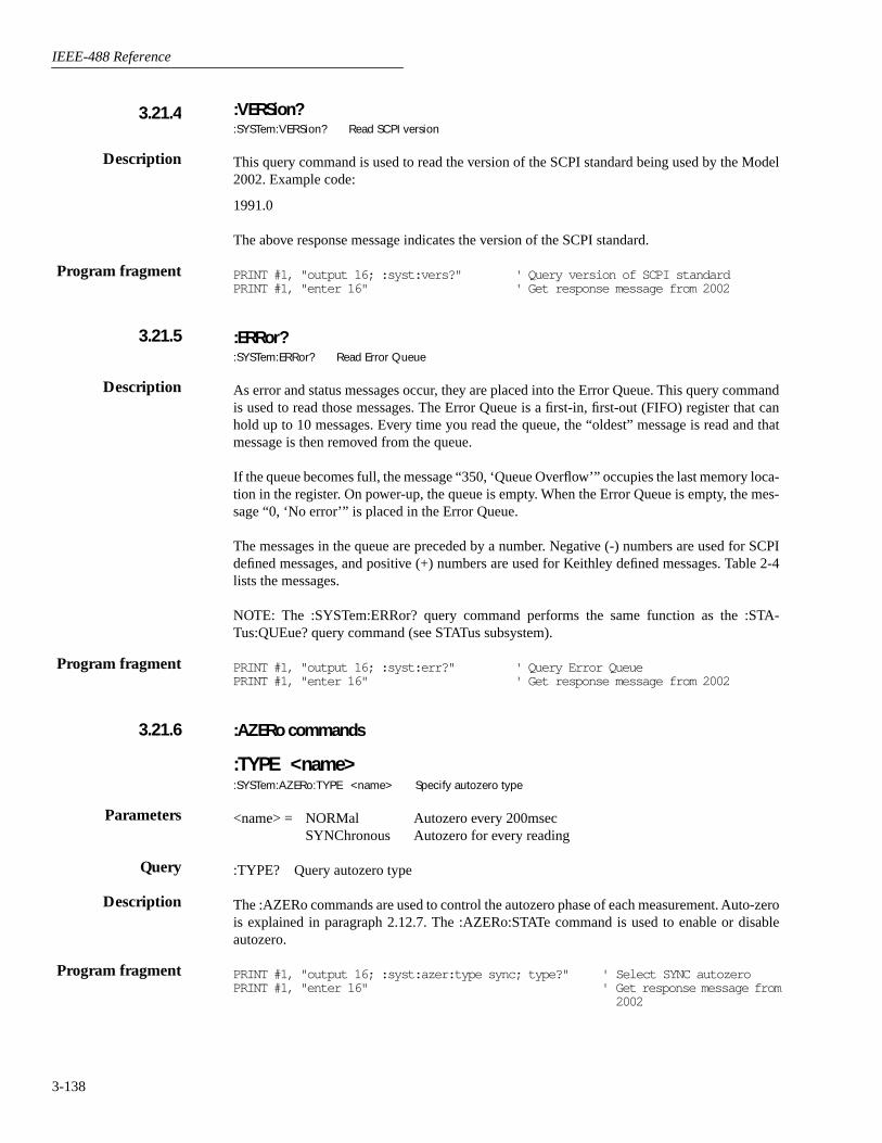
IEEE-488 Reference
3-138
:VERSion?:SYSTem:VERSion? Read SCPI version
This query command is used to read the version of the SCPI standard being used by the Model2002. Example code:
1991.0
The above response message indicates the version of the SCPI standard.
PRINT #1, "output 16; :syst:vers?" ' Query version of SCPI standardPRINT #1, "enter 16" ' Get response message from 2002
:ERRor?:SYSTem:ERRor? Read Error Queue
As error and status messages occur, they are placed into the Error Queue. This query commandis used to read those messages. The Error Queue is a first-in, first-out (FIFO) register that canhold up to 10 messages. Every time you read the queue, the “oldest” message is read and thatmessage is then removed from the queue.
If the queue becomes full, the message “350, ‘Queue Overflow’” occupies the last memory loca-tion in the register. On power-up, the queue is empty. When the Error Queue is empty, the mes-sage “0, ‘No error’” is placed in the Error Queue.
The messages in the queue are preceded by a number. Negative (-) numbers are used for SCPIdefined messages, and positive (+) numbers are used for Keithley defined messages. Table 2-4lists the messages.
NOTE: The :SYSTem:ERRor? query command performs the same function as the :STA-Tus:QUEue? query command (see STATus subsystem).
PRINT #1, "output 16; :syst:err?" ' Query Error QueuePRINT #1, "enter 16" ' Get response message from 2002
:AZERo commands
:TYPE <name>:SYSTem:AZERo:TYPE <name> Specify autozero type
<name> = NORMal Autozero every 200msecSYNChronous Autozero for every reading
:TYPE? Query autozero type
The :AZERo commands are used to control the autozero phase of each measurement. Auto-zerois explained in paragraph 2.12.7. The :AZERo:STATe command is used to enable or disableautozero.
PRINT #1, "output 16; :syst:azer:type sync; type?" ' Select SYNC autozeroPRINT #1, "enter 16" ' Get response message from
2002
3.21.4
Description
Program fragment
3.21.5
Description
Program fragment
3.21.6
Parameters
Query
Description
Program fragment

IEEE-488 Reference
3-139
:STATe <b>:SYSTem:AZERo:STATe <b> Control autozero
<b> = 1 or ON Enable autozero0 or OFF Disable autozero
:STATe? Query state of autozero
This command is used to disable or enable autozero.
Important Note: Before you can enable or disable auto-zero, the Model 2002 must first be in theidle state. The Model 2002 can be placed in the idle state by first disabling continuous initiation(:INITiate:CONTinuous OFF), and then sending the :ABORt command. After sending the:STATe command, readings can be re-started by sending :INITiate:CONTinuous ON or:INITiate.
PRINT #1, "output 16; :init:cont off; :abor" ' Place 2002 in idlePRINT #1, "output 16; :syst:azer:stat off; stat?" ' Disable autozeroPRINT #1, "enter 16" ' Get response from 2002LINE INPUT #2, a$ ' Read responsePRINT a$ ' Display responsePRINT #1, "output 16; :init:cont on" ' Take 2002 out of idle
NOTE: When finished, be sure to re-enable autozero.
:AMEThod <name>:SYSTem:AMEThod <name> Specify acquisition method
<name> = NORMal Normal acquisition method for bufferBURSt Burst acquisition method for bufferASTReam ASCII stream modeSSTReam Single integer stream mode
:AMEThod? Query acquisition method
BURST and NORMal
These parameters are used to specify the acquisition method for storing readings in the buffer.With the NORMAL method, readings are stored at a rate that is determined by how the instru-ment is configured (i.e. integration period, resolution and filter).
When BURSt acquisition is selected, the Model 2002 is automatically configured for optimumspeed (The instrument’s previous configuration is restored when normal acquisition is againselected). The burst mode configures the buffer for compact grouping (see :TRACe:EGRoup).Thus, the time-stamp is not available for burst acquisition. See paragraph 2.8 for complete infor-mation on burst mode.
Before selecting the burst acquisition mode, configure the Model 2002 for the desired measure-ments (such as a valid function, a manual measurement range, and a math calculation(:CALCulate1) if desired). Also, configure the buffer for the number of readings to be stored(see Trace subsystem).
After burst acquisition is selected, the instrument goes into the idle state (ARM indicator off).After taking the instrument out of idle (:INITiate or :INITiate:CONTinuous ON), the pro-grammed scan event (:see :ARM:LAYer2 SOURce) will start the storage process.
Parameters
Query
Description
Program fragment
3.21.7
Parameters
Query
Description

IEEE-488 Reference
3-140
When storage starts, the ARM indicator turns on to denote that raw input readings are beingstored in the buffer. After the storage process is finished, the * indicator turns on to denote thatpost processing (i.e. math calculations) is being performed on the readings. When post process-ing is finished, the * indicator turns off and the instrument returns to the idle state. The Tracesubsystem is used to read the buffer.
Sending a bus command to the Model 2002 while raw readings are being acquired aborts theacquisition and post processes the readings already stored in the buffer.
ASTReam and SSTReam
These two “stream” parameters are used to send “fresh” A/D readings over the IEEE-488 bus atmaximum speed. The ASTReam parameter is used to send readings in the ASCII format, andthe SSTReam parameter is used to send readings in the Single Integer (counts) format. Thestream modes can be used for the following functions: DCV, ACV (average and RMS), DCI,ACI (average and RMS) and Ω2. TEMP, FREQ, Ω4, in-circuit current, and peak measurementscannot be used with stream mode.
With ASTReam, up to 1000 readings per second can be sent over the bus, and with SSTReam,up to 2000 readings per second can be sent. Once the Model 2002 is placed in a stream mode,one A/D reading is sent over the bus every time the instrument is addressed to talk.
ASCII stream mode:
With ASTReam, only the reading is sent. All other data elements (units, reading number, timestamp, etc.) are not included.
A line feed (LF) with EOI is used as a terminator for each reading. An overflowed reading isreturned as a +/-30,000 count reading. For example, a 10kΩ resistor being measured on the 2kΩrange will return the following overranged reading:
+3.0000E+03 (Overranged ASTReam reading)
Single integer stream mode:
The SSTReam mode sends single precision integer readings. Each reading is 2-bytes in size andis not terminated by a line feed (LF). EOI is asserted with the second byte of each reading.
With SSTReam, only the number of A/D counts are sent. For example, a 1.5V reading on the2V range will be sent as follows:
15000
The same reading (1.5V) on the 20V range is sent as follows:
1500
An overrange reading is expressed as +/-30,000 counts. For example, if a 50kΩ resistor is mea-sured on the 20kΩ range, the overranged reading will be expressed as follows:
30000 (Overranged SSTReam reading)
Operating considerations:
Before going into a stream mode, make sure the instrument is on the desired function and range.Once in a stream mode, all front panel controls are disabled, and all SCPI and Common com-mands are ignored.

IEEE-488 Reference
3-141
Before going into the SSTReam mode, make sure the data format byte order is correct for yourcomputer. IBM and IBM compatibles require the swapped byte order and HP requires normalbyte order (see :FORMat:BORDer).
Important Note: Before going into a stream mode, the instrument must be in continuous initia-tion. If continuous initiation is disabled (or you are not sure), send the following command toenable it:
:INITiate:CONTinuous ON
When the :AMEThod command is sent with one of the stream parameters, the instrument willgo into the stream mode and lock out all front panel controls, and ignore all SCPI and Commoncommands. When a stream mode is entered, you must wait before addressing the Model 2002to talk. The minimum delay period is dependent on function and range (see Table 3-17). In astream mode, the instrument configures itself as follows:
Auto zero disabled (:SYSTem:AZERo:STATe OFF)CALC 1 disabled (:CALCulate[1]:STATe OFF) Line synchronization disabled (:SYSTem:LSYNc:STATe OFF)
For each valid function:
<function> = :VOLTage:AC:VOLTage:DC:CURRent:AC:CURRent:DC:RESistance
Auto range disabled (<function>:RANGe:AUTO OFF)NPLC = 0.01 (<function>:NPLCycles 0.01)Auto NPLC disabled (<function>:NPLCycles:AUTO OFF)Resolution = 4½ digits (<function>:DIGits 5)Auto resolution disabled (<function>:DIGits:AUTO OFF)Filter disabled (<function>:AVERage:STATe OFF)Auto filter disabled (<function>:AVERage:AUTO OFF)Reference disabled (<function>:REFerence:STATe OFF)
The stream mode is cancelled when a device clear (DCL or SDC) is sent to the Model 2002.Keep in mind that the instrument remains at the settings that it assumed for the stream mode.After cancelling the stream mode, again wait before sending any more commands. (See Table3-17.)
The delay times in Table 3-17 only account for processing the stream command and the deviceclear command. Commands that precede the stream command must be allowed to finish execut-ing before the stream command is sent. The *OPC? command is recommended for this purpose.When *OPC? is sent, subsequent commands will not execute until the operations of all previouscommands are completed. The use of *OPC? is demonstrated in Program Fragment #2.
Triggering — In stream, the trigger model functions normally except that the Manual and Holdcontrol sources cannot be used. The Group Execute Trigger (GET) is functional when the Buscontrol source is selected. For optimum speed, set up the measure layer for Immediate controlsource, infinite count and zero delay.
Reading Rates — The maximum possible reading rate for the SSTReam mode is 2000 per sec-ond and is only achievable for controllers that can pull each reading out of the Model 2002 inless than 100µsec. The maximum possible reading rate for the ASTReam mode is 1000 per sec-

IEEE-488 Reference
3-142
ond. Maximum reading rates require that the measure layer of the trigger model be configuredfor the Immediate control source, infinite count and zero delay. When externally triggered (EXT,TLINK, TIMER or GET), the maximum reading rate for either stream mode is 680 per second.
Burst acquisition
PRINT #1, "output 16; :syst:amet burs" ' Select burst modePRINT #1, "output 16; :init" ' Start acquisition process
ASTReam mode
PRINT #1, "output 16; *opc?" ' Send *opc?PRINT #1, "enter 16" ' Wait for operation completePRINT #1, "output 16; :syst:amet astr" ' Go into ASTReam modeSLEEP 1 ' Wait for 1 secondFOR I = 1 TO 200 ' Set counter to loop 200 timesPRINT #1, "enter 16" ' Get reading from 2002
Table 3-17 Minimum delay times for stream mode
Function Range Delay (msec)
DCV 200mV2V20V200V1000V
150160150220210
ACV (RMS and average) 200mV2V20V200V750V
270260210200210
DCI 200µA2mA20mA200mA2A
130140170140190
ACI (RMS and average) 200µA2mA20mA200mA2A
230180230220160
Ω2 20Ω200Ω2kΩ20kΩ200kΩ2MΩ20MΩ200MΩ1GΩ
190180140170270880184019201920
Program fragment #1
Program fragment #2

IEEE-488 Reference
3-143
NEXT I ' Repeat loop until 200 rdgs acquiredPRINT #1, "clear 16" ' Cancel stream modeSLEEP 1 ' Wait 1 second
:LSYNc:STATe <b>:SYSTem:LSYNc:STATe <b> Control line synchronization
<b> = 0 or OFF Disable line synchronization1 or ON Enable line synchronization
:STATe? Query state of line synchronization
This command is used to enable or disable line synchronization. When enabled, the integrationperiod will not start until the beginning of the next power line cycle. For example, if a readingis triggered at the positive peak of a power line cycle, the integration period will not start untilthat power line cycle is completed. The integration period starts when the positive-going sinewave crosses zero volts.
With line synchronization disabled, the integration period starts when the reading is triggered.See paragraph 2.12.7 for details.
IMPORTANT NOTE: The Model 2002 must first be in idle before you can enable linesynchronization.
PRINT #1, "output 16; :init:cont off; :abor" ' Place 2002 in idlePRINT #1, "output 16; :syst:lsyn:stat on; stat?" ' Enable line syncPRINT #1, "enter 16" ' Get response from 2002PRINT #1, "output 16; :init"" ' Take 2002 out of idle
:KEY <NRf>:SYSTem:KEY <NRf> Simulate key-press
<NRf> = 1 Up Arrow <NRf> = 16 NEXT2 TEMP 17 Down Arrow3 Left Arrow 18 ENTER4 MENU 19 Ω45 ACI 20 FILTER6 STORE 21 SCAN7 LOCAL 22 ACV8 PREV 23 REL9 AUTO 26 FREQ10 Right Arrow 27 MAT11 EXIT 28 CONFIG12 Ω2 29 DCI13 RECALL 30 TRIG14 CHAN 31 INFO15 DCV
:KEY? Query last “pressed” key.
This command is used to simulate front panel key presses. For example, to select DCV you cansend the following command to simulate pressing the DCV key:
3.21.8
Parameters
Query
Description
Program fragment
3.21.9
Parameters
Query
Description

IEEE-488 Reference
3-144
:syst:key 15
The parameter listing provides the key-press code in numeric order. Figure 3-39 also providesthe key-press code.
The :KEY command allows you to select the NEXT displays over the bus. Sending :SYS-Tem:KEY 16 over the bus is the same as a single press of the NEXT key. Sending :SYS-Tem:KEY 8 is the same as a single press of the PREV key. The NEXT display that is selecteddepends on which function is currently selected and how many times the NEXT key is “pressed”using the :KEY command. The instrument can always be returned to the normal display by“pressing” the PREV key a similar number of times, or by sending the :DISPlay:CNDisplaycommand.
For example, on the FREQ function, you can display the trigger level by “pressing” the NEXTkey twice as follows:
:syst:key 16; key 16
To return to the normal display, “press” the PREV key twice as follows:
:syst:key 8; key 8
The queue for the :KEY? query command can only hold one key-press. When :KEY? is sentover the bus, and the Model 2002 is addressed to talk, the key-press code number for the last keypressed (either physically or with :KEY) is sent to the computer.
PRINT #1, "output 16; :syst:key 29" ' Select DCI functionSLEEP 3 ' Wait 3 secondsPRINT #1, "output 16; :sys:key 16; key 16" ' Select Zero Center Bar GraphSLEEP 3 ' Wait 3 secondsPRINT #1, "output 16; :syst:key 8; key 8" ' Return to normal display
Figure 3-39Key-press codes
NEXT
DISPLAY
PREV
POWER
DCV ACV DCI ACI Ω2 Ω4 FREQ TEMP
REL TRIG STORE RECALL
INFO LOCAL CHAN SCAN CONFIG MENU EXIT ENTER
RANGE
AUTOFILTER MATH
RANGE
SENSEΩ 4 WIRE
HI
INPUT
LO
INPUTS
CAL
500VPEAK
F R
FRONT/REAR
2A 250V
AMPS
350VPEAK
1100VPEAK!
16
23
31
7
30
6
14
21
13
20
28
4
27
3
11
18
10
17
9
8 15 22 29 5 12 19 26 2 1
2002 MULTIMETER
Program fragment

IEEE-488 Reference
3-145
:CLEar:SYSTem:CLEar Clear Error Queue
This action command is used to clear the Error Queue of messages.
PRINT #1, "output 16; :syst:cle" ' Clear Error Queue
:LFRequency:SYSTem:LFRequency Query power line frequency
This query command is used to read the frequency of the power line that powers the Model2002.
PRINT #1, "output 16; :syst:lfr?" ' Query the power linePRINT #1, "enter 16" ' Get response from 2002
:DATE <yr>, <mo>, <day>:SYSTem:DATE <yr>, <mo>, <day> Set date for clock
<yr> = 1993 to 2092 Specify year<mo> = 1 to 12 Specify month<day>= 1 to 31 Specify day
:DATE? Query the date
This command is used to set the date for the real-time clock. Setting an invalid date (i.e. Febru-ary 29, 1994) result in an error and the previous date is retained.
PRINT #1, "output 16; :syst:date <1993>, <12>, <1>; date?" ' Set date to December 1, 1993and query
PRINT #1, "enter 16" ' Get responsemessage from2002
:TIME <hr>, <min>, <sec>:SYSTem:TIME <hr>, <min>, <sec> Set time for clock
<hr> = 0 to 23 Specify hour (24 hr format)<min> = 0 to 59 Specify minute<sec>= 0.00 to 59.99 Specify second (rounded to 1/100 sec.)
:TIME? Query the time
This command is used to set the time for the real-time clock. Note that the time must be set usingthe 24-hour format (i.e. hour 13 is 1PM). Setting an invalid time results in an error and the pre-vious time is retained.
:TIME? returns the time to nearest hundreth of a second.
PRINT #1, "output 16; :syst:time <14>, <36>, <0>; time?" ' Set time to 2:36pm and query
PRINT #1, "enter 16" ' Get response mes-sage from 2002
3.21.10
Description
Program fragment
3.21.11
Description
Program fragment
3.21.12
Parameters
Query
Description
Program fragment
3.21.13
Parameters
Query
Description
Program fragment

IEEE-488 Reference
3-146
:TSTamp commands
The following commands are used to configure and control the timestamp. For more informa-tion on timestamp, see paragraphs 3.14 (:FORMat:ELEMents) and 3.22.7 (:TRACe:TSTamp:FORMat).
:TYPE <name>:SYSTem:TSTamp:TYPE <name> Select timestamp type
<name> = RELative Select relative-time timestamp1
RTClock Select real-time timestamp2
1 RELative is a 55 day (max.) clock at a 1µs resolution.2 RTCLock is a 100 year (max.) calendar at a 10ms resolution.
:TYPE? Query timestamp type
This command is used to select the timestamp type. RTClock selects the real-time clock time-stamp. Readings are reference to the date and time. RELative selects the relative-time time-stamp. Readings are referenced (in seconds) to a timer. The timer starts at zero seconds whenthe instrument is turned on or when the timestamp is reset (see next command).
PRINT #1, "output 16; :syst:tst:type rtc; type?" ' Select RTClock and queryPRINT #1, "enter 16" ' Get response message from
2002
:RELative:RESet:SYSTem:TSTamp:RELative:RESet Reset relative timestamp to 0.
This action command is used to reset the relative-time timestamp to zero seconds.
PRINT #1, "output 16; :syst:tst:rel:res" ' Reset relative timestamp
:RNUMber:RESet:SYSTem:RNUMber:RESet Reset reading number to zero
When the reading number is included as a GPIB data element (see paragraph 3.14; :FOR-MAT:ELEMents), each reading sent over the bus is assigned a number starting at #0. The read-ing number resets to zero when the instrument is turned on or when this action command isasserted.
PRINT #1, "output 16; "syst:rnum:res" ' Reset reading number
3.21.14
Parameters
Query
Description
Program fragment
Description
Program fragment
3.21.15
Program fragment

IEEE-488 Reference
3-147
3.22 :TRACe subsystem
The commands in this subsystem are used to configure and control data storage into the buffer.The commands are summarized in Table 3-14. See paragraph 2.8 for more information aboutthe buffer.
:TRACe|:DATA
The bar (|) indicates that :TRACe or :DATA can be used as the root command for this subsystem.From this point on, the documentation in this manual uses :TRACe. If you prefer to use :DATA,simply replace all the :TRACe command words with :DATA.
:CLEar:TRACe:CLEar Clear buffer
This action command is used to clear the buffer of readings. If you do not clear the buffer, asubsequent store will overwrite the old readings. If the subsequent store is aborted before thebuffer becomes full, you could end up with some “old” readings still in the buffer.
PRINT #1, "output 16; :trac:clear" ' Clear buffer
:FREE?:TRACe:FREE? Read status of memory
This command is used to read the status of storage memory. After sending this command andaddressing the Model 2002 to talk, two values separated by commas are sent to the computer.The first value indicates how many bytes of memory are available, and the second value indi-cates how many bytes are reserved to store readings.
PRINT #1, "output 16; :trac:free?" ' Query status of memoryPRINT #1, "enter 16" ' Get response from 2002
:EGRoup <name>:TRACe:EGRoup <name> Specify element group
<name> = FULL Time stamp included with each stored readingCOMPact Time stamp not included
:EGRoup? Query element group
This command is used to select the element group that is sent with each reading. Common toboth element groups are function, channel (if applicable) and buffer location. The FULL ele-ment group includes the time stamp. The first reading in the buffer has a time stamp of 0 sec-onds. The time stamp for all subsequent readings are then referenced to the first reading.
The COMpact element group excludes the time stamp. This allows more readings to be storedin the buffer (see :POINts).
PRINT #1, "output 16; :trac:egr comp; egr?" ' Select compact element groupPRINT #1, "enter 16" ' Get response from 2002
3.22.1
Description
Program fragment
3.22.2
Description
Program fragment
3.22.3
Parameters
Query
Description
Program fragment

IEEE-488 Reference
3-148
:POINts <n>:TRACe:POINts <n> Specify buffer size
No memoryoption MEM 1 MEM 2
<n> = 2 to 404 2 to 1381 2 to 5980 (Full)2 to 2027 2 to 6909 2 to 29908 (Compact)
MAXimum 404 1381 5980 (Full)2027 6909 29908 (Compact)
DEFault 100 (all cases)MINimum 2 (all cases)
:POINts?
This command is used to specify the size of the buffer. Notice that the valid parameter rangedepends on which memory option is installed, and which element group (full or compact) isbeing used (see :EGRoup).
PRINT #1, "output 16; :trac:poin 50; poin?" ' Set size of bufferPRINT #1, "enter 16" ' Get response from 2002
:AUTO <b>:TRACe:POINts:AUTO <b> Control auto buffer sizing
<b> = 0 or OFF Disable auto buffer sizing1 or ON Enable auto buffer sizing
:AUTO?
This command is used to enable or disable auto buffer sizing. When enabled, the buffer sizedefaults to the measure count value in the Trigger Model (see :TRIGger:COUNt in Trigger sub-system). With auto buffer enabled, changing the Trigger Model’s measure count value changesthe buffer size to that value.
Disabling auto buffer sizing does not affect the size of the buffer. It simply means that you mustthen use the :POINts command to change the buffer size.
If you use the :POINts command to change the buffer size while auto is enabled, the buffer sizechanges to that value and auto buffer sizing disables.
If you try to enable auto buffer sizing while the measure count is programmed for infinite, anerror will occur and the command will be ignored. You cannot have an infinite buffer size.
PRINT #1, "output 16; :trig:coun 200" ' Set measure countPRINT #1, "output 16; :trac:poin:auto on; auto?" ' Enable auto buffer sizingPRINT #1, "enter 16" ' Get response from 2002
:FEED <name>:TRACe:FEED <name> Specify readings source
<name> = SENSe[1] Put raw readings in bufferCALCulate[1] Put calculated readings in bufferNONE Put no readings in buffer
3.22.4
Parameters
Query
Description
Program fragment
Parameters
Query
Description
Program fragment
3.22.5
Parameters

IEEE-488 Reference
3-149
:FEED? Query buffer feed
This command is used to select the source of readings to be placed in the buffer. With SENSe[1]selected, raw readings are placed in the buffer when storage is performed. With CALCulate[1]selected, calculated math readings (POLYnomial or PERCent or NONE) are placed in thebuffer.
With NONE selected, no readings are placed in the buffer when storage is performed over thebus.
PRINT #1, "output 16; :trac:feed calc; feed?" ' CALC1 buffer readingsPRINT #1, "enter 16" ' Get response from 2002
:[PERCent] <n>:TRACe:FEED:PRETrigger:AMOunt:[PERCent] <n> Specify percentof pre-trigger readings
<n> = 0 to 100 % of buffer for pre-trigger readingsDEFault 50% of buffer for pre-trigger readingsMINimum 0% of buffer for pre-trigger readingsMAXimum 100% of buffer for pre-trigger readings
:[PERCent]?
This command is used to specify how much of the defined buffer (:POINts) will be used to storepre-triggered readings. When a pre-trigger store is started (see :FEED:CONTrol), readings arecontinuously stored in the buffer. When the pre-trigger event occurs (see :PRETrig-ger:SOURce), post-trigger readings will then fill the part of the buffer that is not reserved forpre-trigger readings.
For example, assume 25% of a 100 point buffer is reserved for pre-trigger readings. When thepre-trigger store is started, readings continuously fill the buffer. When the pre-trigger eventoccurs, subsequent readings will then be stored starting at buffer location 26 and continue untilbuffer location 100 is filled. Storage stops after buffer location 100 is filled. The result is 25 pre-trigger readings and 75 post-trigger readings. See paragraph 2.8.2 for more information aboutpre-trigger.
PRINT #1, "output 16; :trac:feed:pret:amo 25; amo?" ' 25% for pre-triggerrdgs
PRINT #1, "enter 16" ' Get response from 2002
:READings <n>:TRACe:FEED:PRETrigger:AMOunt:READings <n> Specify number of pre-trigger readings
No memoryoption MEM 1 MEM 2
<n> = 0 to 404 0 to 1381 0 to 5980 (Full)0 to 2027 0 to 6909 0 to 29908 (Compact)
MAXimum Present buffer size (which is set by TRACe:POINts)DEFault Half present buffer size (which is set by TRACe:POINts)MINimum 0 (all cases)
Query
Description
Program fragment
Parameters
Query
Description
Program fragment
Parameters

IEEE-488 Reference
3-150
:READ?
This command is used to specify how much of the defined buffer (:POINts) will be used to storepre-triggered readings. This command is essentially the same as the :PERCent command exceptthe amount is expressed as an exact value instead of a percent.
Sending a value that exceeds the defined size of the buffer (see :POINts) generates an error. Thecommand is ignored.
PRINT #1, "output 16; :trac:poin; 75" ' Set buffer sizePRINT #1, "output 16; :trac:feed:pret:amo:read 30; read?" ' 30 pre-trugger
rdgs for bufferPRINT #1, "enter 16" ' Get response from
2002
:SOURce <name>:TRACe:FEED:PRETrigger:SOURce <name> Specify pre-trigger event
<name> = EXTernal Use External Trigger as pre-trigger eventTLINk Use Trigger Link as pre-trigger eventBUS Use bus trigger as pre-trigger eventMANual Use TRIG key as pre-trigger event
:SOURce? Query buffer source.
This command is used to specify the event for the pre-trigger storage mode. With the pre-triggermode selected (:CONTrol, PRETrigger), readings are continuously stored in the buffer whilewaiting for the pre-trigger source event.
With EXTernal source selected, an external trigger via the rear panel EXTERNAL TRIGGERInput provides the pre-trigger event.
With TLINk selected, an input trigger via the Trigger Link provides the pre-trigger event. TheTrigger Link line used for the input trigger is programmed from the Trigger subsystem (see:TRIGger:TCONfigure command path).
With BUS selected, a GPIB bus trigger (GET or *TRG) provides the pre-trigger event.
With MANual selected, pressing the front panel TRIG key provides the pre-trigger event.
PRINT #1, "output 16; :trac:feed:pret:sour bus; sour?" ' Select bus pre-trig-ger
PRINT #1, "enter 16" ' Get response from2002
:CONTrol <name>:TRACe:FEED:CONTrol <name> Specify buffer control
<name> = NEVer Disables buffer storageNEXT Fills buffer and stopsALWays Continuously stores readings in bufferPRETrigger Use Pretrigger mode to store readings
:CONTrol? Query buffer control
Query
Description
Program fragment
Parameters
Query
Description
Program fragment
Parameters
Query

IEEE-488 Reference
3-151
This command is used to select the buffer control. With NEVer selected, storage into the bufferis disabled. After cycling power, NEVer is selected. With any of the other selections, storage isperformed as long as buffer feed is not set for NONE (see :TRACe:FEED NONE). WhenNEXT is selected, the storage process starts, fills the buffer and then stops. The buffer size isspecified by the :POINts command.
When ALWays is selected, the storage process starts and continues to store readings even afterthe buffer fills. After the buffer fills, readings overwrite the previously stored readings.
When PRETrigger is selected, the buffer stores readings continuously (like ALWays) until theprogrammed pre-trigger event occurs. When the pre-trigger event occurs, the section of thebuffer specified for post-trigger readings fill with new readings. The storage process stops whenthe post trigger portion of the buffer becomes full with new readings (see:TRACe:FEED:PRETrigger).
PRINT #1, "output 16; :trac:feed:cont next; cont?" ' Fill buffer and stopPRINT #1, "enter 16" ' Get response from 2002
:DATA?:TRACe:DATA? Send buffer readings
When this command is sent and the Model 2002 is addressed to talk, all the readings stored inthe buffer are sent to the computer. The format that readings are sent over the bus is controlledby the :FORMat subsystem.
PRINT #1, "output 16; :trac:data?" ' Read entire bufferPRINT #1, "enter 16" ' Get readings from 2002
:TSTamp:FORMat <name>:TRACe:TSTamp:FORMat <name> Select timestamp format
<name> = ABSolute Reference to first buffer readingDELTa Time between buffer readings
:FORMat? Query timestamp format
This command is used to select the timestamp format for buffer readings. With ABSoluteselected, each timestamp is referenced to the first reading stored in the buffer. With DELTaselected, timestamps provide the time between each buffer reading. See paragraphs 3.14(:FORMat: ELEMents) and 3.21.14 (:SYSTem:TSTamp) for more information.
PRINT #1, "output 16; :trac:tst:form delt; form?" ' Select DELTa timestamp andquery
PRINT #1, "enter 16" ' Get response from 2002
Description
Program fragment
3.22.6
Description
Program fragment
3.22.7
Parameters
Query
Description
Program fragment

IEEE-488 Reference
3-152
3.23 Trigger subsystem
The Trigger subsystem is made up of a series of commands and subsystems to configure thethree layers of the Trigger Model (see paragraph 2.7 and 3.8 for details). These commands andsubsystems are summarized in Table 3-15.
:INITiate commands
[:IMMediate]:INITiate[:IMMediate] Take 2002 out of idle
This command takes the Model 2002 out of the idle state. After all programmed operations arecompleted, the instrument leaves the trigger layers and returns to the idle state if continuous ini-tiation is disabled; (see next command).
PRINT #1, "output 16; :init" ' Take 2002 out of idle
:CONTinuous <b>:INITiate:CONTinuous <b> Control continuous initiation
<b> = 0 or OFF Disable continuous initiation1 or ON Enable continuous initiation
:CONTinuous? Query continuous initiation
When continuous initiation is selected (ON), the instrument is taken out of the idle state. At theconclusion of all programmed operations, the instrument returns to Arm Layer 1.
PRINT #1, "output 16; :init:cont on; cont?" ' Enable continuous initiationPRINT #1, "enter 16" ' Get response from 2002
:ABORt:ABORt Abort operation
When this action command is sent, the Model 2002 aborts operation and returns to the top ofthe Trigger Model. If continuous initiation is disabled, the instrument goes the idle state. If con-tinuous initiation is enabled, operation continues on into Arm Layer 1.
The abort command resets the source bypasses of the Trigger Model. If scanning, the scanpointer resets back to the first channel in the scan list.
PRINT #1, "output 16; abor" ' Abort operation
:IMMediate:ARM[:SEQuence[1]][:LAYer[1]]:IMMediate Bypass arm control source:ARM[:SEQuence[1]]:LAYer2:IMMediate Bypass scan control source and delay:TRIGger:[:SEQuence[1]]:IMMediate Bypass measure control source and delay
3.23.1
Description
Program fragment
Parameters
Query
Description
Program fragment
3.23.2
Description
Program fragment
3.23.3
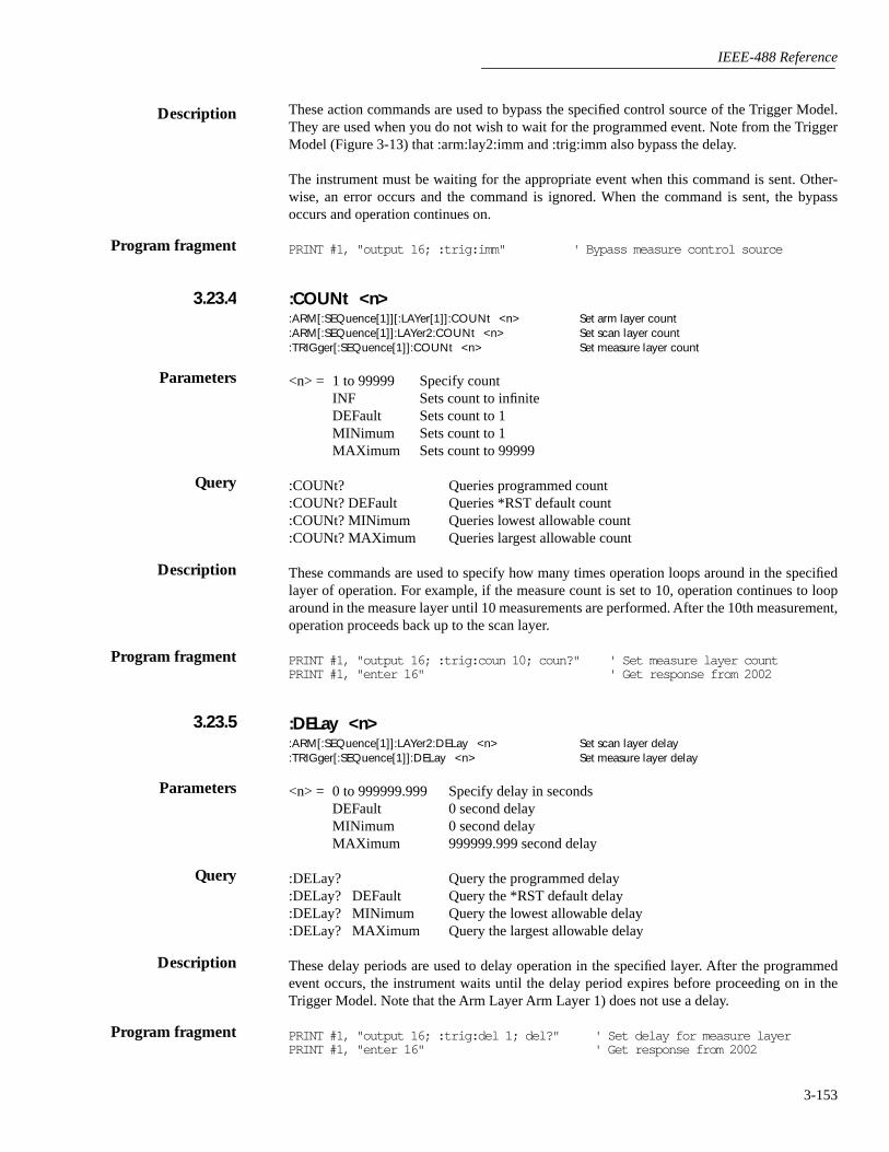
IEEE-488 Reference
3-153
These action commands are used to bypass the specified control source of the Trigger Model.They are used when you do not wish to wait for the programmed event. Note from the TriggerModel (Figure 3-13) that :arm:lay2:imm and :trig:imm also bypass the delay.
The instrument must be waiting for the appropriate event when this command is sent. Other-wise, an error occurs and the command is ignored. When the command is sent, the bypassoccurs and operation continues on.
PRINT #1, "output 16; :trig:imm" ' Bypass measure control source
:COUNt <n>:ARM[:SEQuence[1]][:LAYer[1]]:COUNt <n> Set arm layer count:ARM[:SEQuence[1]]:LAYer2:COUNt <n> Set scan layer count:TRIGger[:SEQuence[1]]:COUNt <n> Set measure layer count
<n> = 1 to 99999 Specify countINF Sets count to infiniteDEFault Sets count to 1MINimum Sets count to 1MAXimum Sets count to 99999
:COUNt? Queries programmed count:COUNt? DEFault Queries *RST default count:COUNt? MINimum Queries lowest allowable count:COUNt? MAXimum Queries largest allowable count
These commands are used to specify how many times operation loops around in the specifiedlayer of operation. For example, if the measure count is set to 10, operation continues to looparound in the measure layer until 10 measurements are performed. After the 10th measurement,operation proceeds back up to the scan layer.
PRINT #1, "output 16; :trig:coun 10; coun?" ' Set measure layer countPRINT #1, "enter 16" ' Get response from 2002
:DELay <n>:ARM[:SEQuence[1]]:LAYer2:DELay <n> Set scan layer delay:TRIGger[:SEQuence[1]]:DELay <n> Set measure layer delay
<n> = 0 to 999999.999 Specify delay in secondsDEFault 0 second delayMINimum 0 second delayMAXimum 999999.999 second delay
:DELay? Query the programmed delay:DELay? DEFault Query the *RST default delay:DELay? MINimum Query the lowest allowable delay:DELay? MAXimum Query the largest allowable delay
These delay periods are used to delay operation in the specified layer. After the programmedevent occurs, the instrument waits until the delay period expires before proceeding on in theTrigger Model. Note that the Arm Layer Arm Layer 1) does not use a delay.
PRINT #1, "output 16; :trig:del 1; del?" ' Set delay for measure layerPRINT #1, "enter 16" ' Get response from 2002
Description
Program fragment
3.23.4
Parameters
Query
Description
Program fragment
3.23.5
Parameters
Query
Description
Program fragment
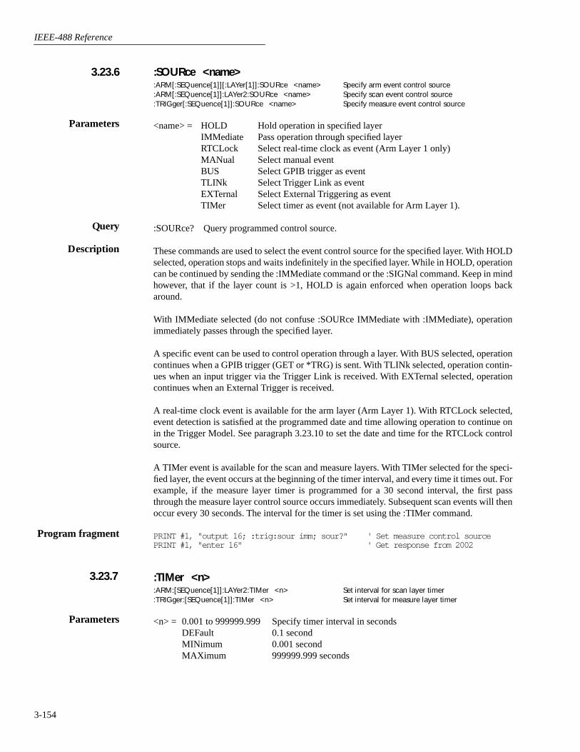
IEEE-488 Reference
3-154
:SOURce <name>:ARM[:SEQuence[1]][:LAYer[1]]:SOURce <name> Specify arm event control source:ARM[:SEQuence[1]]:LAYer2:SOURce <name> Specify scan event control source:TRIGger[:SEQuence[1]]:SOURce <name> Specify measure event control source
<name> = HOLD Hold operation in specified layerIMMediate Pass operation through specified layerRTCLock Select real-time clock as event (Arm Layer 1 only)MANual Select manual eventBUS Select GPIB trigger as eventTLINk Select Trigger Link as eventEXTernal Select External Triggering as eventTIMer Select timer as event (not available for Arm Layer 1).
:SOURce? Query programmed control source.
These commands are used to select the event control source for the specified layer. With HOLDselected, operation stops and waits indefinitely in the specified layer. While in HOLD, operationcan be continued by sending the :IMMediate command or the :SIGNal command. Keep in mindhowever, that if the layer count is >1, HOLD is again enforced when operation loops backaround.
With IMMediate selected (do not confuse :SOURce IMMediate with :IMMediate), operationimmediately passes through the specified layer.
A specific event can be used to control operation through a layer. With BUS selected, operationcontinues when a GPIB trigger (GET or *TRG) is sent. With TLINk selected, operation contin-ues when an input trigger via the Trigger Link is received. With EXTernal selected, operationcontinues when an External Trigger is received.
A real-time clock event is available for the arm layer (Arm Layer 1). With RTCLock selected,event detection is satisfied at the programmed date and time allowing operation to continue onin the Trigger Model. See paragraph 3.23.10 to set the date and time for the RTCLock controlsource.
A TIMer event is available for the scan and measure layers. With TIMer selected for the speci-fied layer, the event occurs at the beginning of the timer interval, and every time it times out. Forexample, if the measure layer timer is programmed for a 30 second interval, the first passthrough the measure layer control source occurs immediately. Subsequent scan events will thenoccur every 30 seconds. The interval for the timer is set using the :TIMer command.
PRINT #1, "output 16; :trig:sour imm; sour?" ' Set measure control sourcePRINT #1, "enter 16" ' Get response from 2002
:TIMer <n>:ARM:[SEQuence[1]]:LAYer2:TIMer <n> Set interval for scan layer timer:TRIGger:[SEQuence[1]]:TIMer <n> Set interval for measure layer timer
<n> = 0.001 to 999999.999 Specify timer interval in secondsDEFault 0.1 secondMINimum 0.001 secondMAXimum 999999.999 seconds
3.23.6
Parameters
Query
Description
Program fragment
3.23.7
Parameters

IEEE-488 Reference
3-155
:TIMer? Query programmed timer interval:TIMer? DEFault Query *RST default timer interval:TIMer? MINimum Query lowest allowable timer interval:TIMer? MAXimum Query largest allowable timer interval
These commands are used to set the interval for the scan layer and measure layer timers. Notethat the timer is in effect only if the timer is the selected control source. Also, note that the armlayer (Arm Layer 1) does not use a timer.
PRINT #1, "output 16; :trig:tim .25; tim?" ' Set timer for Measure LayerPRINT #1, "enter 16" ' Get response from 2002
:SIGNal:ARM[:SEQuence[1]][:LAYer[1]]:SIGNal Bypass arm control source:ARM[:SEQuence[1]]:LAYer2:SIGNal Bypass scan control source:TRIGger[:SEQuence[1]]:SIGNal Bypass measure control source
These action commands are used to bypass the specified control source and also when you donot wish to wait for the programmed event. Keep in mind that the instrument must be waitingfor the appropriate event when the command is sent. Otherwise, an error occurs and this com-mand is ignored.
PRINT #1, "output 16; :trig:sign" ' Bypass measure control source
TCONfigure commands
:PROTocol <name>:TRIGger[:SEQuence[1]]:TCONfigure:PROTocol <name> Specify Trigger Link protocol
<name> = ASYNchronous Asynchronous Trigger Link modeSSYNchronous Semi-synchronous Trigger Link mode
:PROTocol? Query programmed Trigger Link protocol
This command is used to select the protocol for the measure layer Trigger Link. With ASYN-chronous selected, separate trigger lines are used for input and output triggers. With SSYNchro-nous selected, a single trigger line is used for both input and output triggers.
Note that the arm and scan layers only use the asynchronous Trigger Link mode and therefore,do not have to be selected.
PRINT #1, "output 16; :trig:tcon:prot ssyn; prot?" ' Select semi-sync proto-col
PRINT #1, "enter 16" ' Get response from 2002
:DIRection <name>:ARM[:SEQuence[1]][:LAYer[1]]:TCONfigure:DIRection <name>Control arm Source Bypass:ARM[:SEQuence[1]]:LAYer2:TCONfigure:DIRection <name>Control scan Source Bypass:TRIGger[:SEQuence[1]]:TCONfigure:DIRection <name>Control measure Source Bypass
<name> = SOURce Enable Source BypassACCeptor Disable Source Bypass
Query
Description
Program fragment
3.23.8
Description
Program fragment
3.23.9
Parameters
Query
Description
Program fragment
Parameters

IEEE-488 Reference
3-156
:DIRection? Query Source Bypass state
When a source bypass is enabled and the External or Trigger Link control source is selected,operation loops around the appropriate control source on the initial pass through that layer. Notethat the source bypass for the scan and measure layers also loops around the delay.
If programmed for another pass through the specified layer (count >1), the bypass loop is not ineffect even though it is still enabled. The bypass loop will be in effect if operation first goes backinto the previous layer (or idle).
Enabling the Source Bypass for the arm and scan layers also enables their output triggers. Whenoperation leaves the arm or scan layer, the appropriate output trigger pulse occurs. If the TriggerLink (TLINk) control source is selected, the output trigger is available on the programmed Trig-ger Link output line. For all other control source selections, the output trigger pulse is availableat the METER COMPLETE Output connector. The output trigger in these two layers is disabledwhen the source bypass is disabled.
The output trigger in the measure layer is always enabled and occurs after the device action.
With ACCeptor selected, the bypass is disabled, This simply means that operation will not pro-ceed through the specified layer until the appropriate event occurs.
PRINT #1, "output 16; :trig:tcon:dir sour; dir?" ' Enable measure source bypass
PRINT #1, "enter 16" ' Get response from 2002
:ASYNchronous commands
:ILINe <NRf>:ARM[:SEQuence[1]][:LAYer[1]]:TCONfigure:ASYNchronous:ILINe <NRf> Select input trigger line; arm
layer:ARM[:SEQuence[1]]:LAYer2:TCONfigure:ASYNchronous:ILINe <NRf> Select input trigger line; scan
layer:TRIGger[:SEQuence[1]]:TCONfigure:ASYNchronous:ILINe <NRf> Select input trigger line; mea-
sure layer
<NRf> = 1 Line #1 <NRf> = 4 Line #42 Line #2 5 Line #53 Line #3 6 Line #6
:ILINe? Query programmed input line #
These commands are used to select an input line for the asynchronous Trigger Link of the spec-ified layer. Keep in mind that asynchronous Trigger Link input and output (see :OLINe) cannotshare the same line. If you assign the input to a line that is already being used for the output, anerror occurs and the command is ignored.
PRINT #1, "output 16; :trig:tcon:asyn:ilin 3; inlin?" ' Select input linePRINT #1, "enter 16" ' Get response from 2002
Query
Description
Program fragment
Parameters
Query
Description
Program fragment
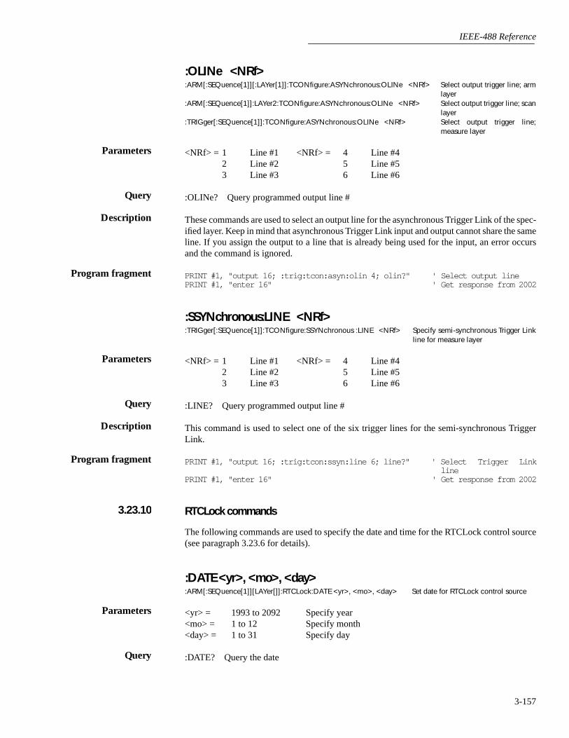
IEEE-488 Reference
3-157
:OLINe <NRf>:ARM[:SEQuence[1]][:LAYer[1]]:TCONfigure:ASYNchronous:OLINe <NRf> Select output trigger line; arm
layer:ARM[:SEQuence[1]]:LAYer2:TCONfigure:ASYNchronous:OLINe <NRf> Select output trigger line; scan
layer:TRIGger[:SEQuence[1]]:TCONfigure:ASYNchronous:OLINe <NRf> Select output trigger line;
measure layer
<NRf> = 1 Line #1 <NRf> = 4 Line #42 Line #2 5 Line #53 Line #3 6 Line #6
:OLINe? Query programmed output line #
These commands are used to select an output line for the asynchronous Trigger Link of the spec-ified layer. Keep in mind that asynchronous Trigger Link input and output cannot share the sameline. If you assign the output to a line that is already being used for the input, an error occursand the command is ignored.
PRINT #1, "output 16; :trig:tcon:asyn:olin 4; olin?" ' Select output linePRINT #1, "enter 16" ' Get response from 2002
:SSYNchronous:LINE <NRf>:TRIGger[:SEQuence[1]]:TCONfigure:SSYNchronous :LINE <NRf> Specify semi-synchronous Trigger Link
line for measure layer
<NRf> = 1 Line #1 <NRf> = 4 Line #42 Line #2 5 Line #53 Line #3 6 Line #6
:LINE? Query programmed output line #
This command is used to select one of the six trigger lines for the semi-synchronous TriggerLink.
PRINT #1, "output 16; :trig:tcon:ssyn:line 6; line?" ' Select Trigger Linkline
PRINT #1, "enter 16" ' Get response from 2002
RTCLock commands
The following commands are used to specify the date and time for the RTCLock control source(see paragraph 3.23.6 for details).
:DATE <yr>, <mo>, <day>:ARM[:SEQuence[1]][LAYer[]]:RTCLock:DATE <yr>, <mo>, <day> Set date for RTCLock control source
<yr> = 1993 to 2092 Specify year<mo> = 1 to 12 Specify month<day> = 1 to 31 Specify day
:DATE? Query the date
Parameters
Query
Description
Program fragment
Parameters
Query
Description
Program fragment
3.23.10
Parameters
Query

IEEE-488 Reference
3-158
This command is used to set the date for the RTCLock control source. Setting an invalid date(i.e. February 29, 1994) for the clock event results in an error and the previous date is retained.
PRINT #1, "output 16; :arm:rtcl:date <1993>, <12>, <1>; date?" ' Set date toDecember 1,1993 and query
PRINT #1, "enter 16" ' Get responsemessage from2002
:TIME <hr>, <min>, <sec>:ARM[:SEQuence[1]][LAYer[]]:RTCLock:TIME <hr>, <min>, <sec> Set time for RTCLock control source
<hr> = 0 to 23 Specify hour (24 hour format)<min> = 0 to 59 Specify minute<sec> = 0.00 to 59.99 Specify second (round to 1/100 sec.)
:DATE? Query the time
This command is used to set the time for the RTCLock control source. Note that the time mustbe set using the 24-hour format (i.e. hour 13 is 1pm). Setting an invalid time results in an errorand the previous time is retained.
:TIME? returns the time to nearest hundreth of a second.
PRINT #1, "output 16; :arm:rtcl:time <14>, <36>, <0>; time?" ' Set time to2:36 pm andquery
PRINT #1, "enter 16" ' Get responsemessage from2002
Description
Program fragment
Parameters
Query
Description
Program fragment

IEEE-488 Reference
3-159
3.24 :UNIT subsystem
The UNIT subsystem is used to configure and control the measurement units for TEMP andACV, and is summarized in Table 3-16.
:TEMPerature <name>:UNIT:TEMPerature <name> Specify TEMP units
<name> = C or CEL °C temperature unitsF or FAR °F temperature unitsK K temperature units
TEMPerature? Query temperature units
This command is used to specify the units for temperature measurements.
PRINT #1, "output 16; :unit:temp f; temp?" ' Select °F for TEMPPRINT #1, "enter 16" ' Get response message from 2002
:AC <name>:UNIT:VOLTage:AC <name> Specify ACV units
<name> = V AC voltage measurement unitsDB dB AC voltage measurement unitsDBM dBm AC voltage measurement units
:AC? Query AC voltage units
This command is used to select the units for ACV measurements. With volt (V) units selected,normal AC voltage measurements are made for the ACV function. With DB units selected, ACdB voltage measurements are performed. The DBM units selection is used to make decibel mea-surements referenced to 1mW. dB and dBm measurements are explained in paragraph 2.4.1(UNITS).
PRINT #1, "output 16; :unit:volt:ac db; ac?" ' Select dB units for ACVPRINT #1, "enter 16" ' Get response message from 2002
:DB:REFerence <n>:UNIT:VOLTage:AC:DB:REFerence <n> Specify dBm reference
<n> = 0.001 to 750 Specify reference in voltsDEFault 1V referenceMINimum 0.001V referenceMAXimum 750V reference
:REFerence?:REFerence? DEFault:REFerence? MINimum:REFerence? MAXimum
Parameters
Query
Description
Program fragment
Query
Description
Program fragment
Parameters
Query

IEEE-488 Reference
3-160
This command is used to specify the dB reference level. When DB units is selected (:VOLT-age:AC: DB), ACV db measurements are made using the specified dB reference level.
The reference level is specified in volts and is not range dependent. For example, a dB referencelevel of 1 is 1V on all ACV measurement ranges.
PRINT #1, "output 16; :unit:volt:ac:db:ref 2; ref?" ' Set dB referencePRINT #1, "enter 16" ' Get response message
from 2002
:DBM:IMPedance <n>:UNIT:VOLTage:AC:DBM:IMPedance <n> Specify dB reference
<n> = 1 to 9999 Specify reference impedance
:IMPedance?:IMPedance? DEFault:IMPedance? MINimum:IMPedance? MAXimum
This command is used to specify the dBm reference impedance level. When dBm units is select-ed ACV dBm measurements are made using the specified dBm reference impedance.
The reference impedance is specified in ohms and is not range dependent. For example, a dBmreference level of 600 is 600Ω on all ACV measurement ranges. A rational number is roundedto the nearest valid integer value.
PRINT #1, "output 16; :unit:volt:ac:dbm:imp 600; imp?" ' Select dBm impedancePRINT #1, "enter 16" ' Get response message
from 2002
Description
Program fragment
Parameters
Query
Description
Program fragment

A
Specifications
A-1
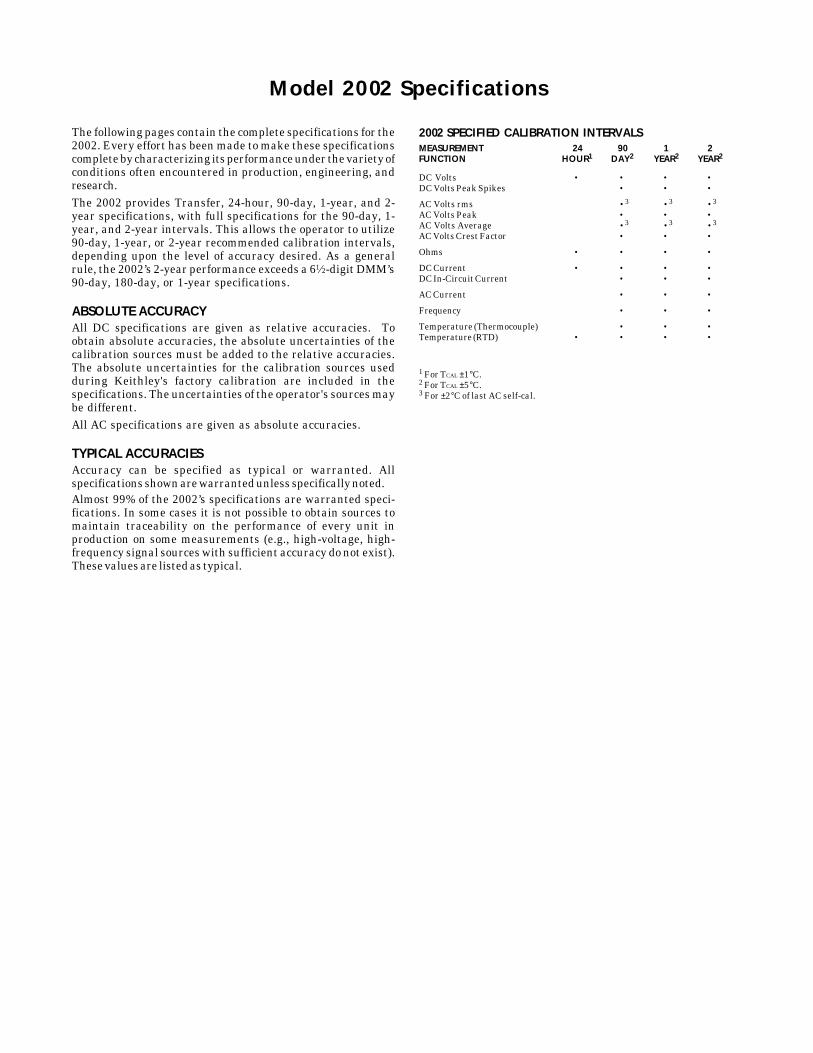
2002 SPECIFIED CALIBRATION INTERVALSMEASUREMENT 24 90 1 2FUNCTION HOUR1 DAY2 YEAR2 YEAR2
DC Volts • • • •DC Volts Peak Spikes • • •
AC Volts rms •3 •3 •3
AC Volts Peak • • •AC Volts Average •3 •3 •3
AC Volts Crest Factor • • •
Ohms • • • •
DC Current • • • •DC In-Circuit Current • • •
AC Current • • •
Frequency • • •
Temperature (Thermocouple) • • •Temperature (RTD) • • • •
1 For TCAL ±1°C.2 For TCAL ±5°C.3 For ±2°C of last AC self-cal.
The following pages contain the complete specifications for the2002. Every effort has been made to make these specificationscomplete by characterizing its performance under the variety ofconditions often encountered in production, engineering, andresearch.The 2002 provides Transfer, 24-hour, 90-day, 1-year, and 2-year specifications, with full specifications for the 90-day, 1-year, and 2-year intervals. This allows the operator to utilize90-day, 1-year, or 2-year recommended calibration intervals,depending upon the level of accuracy desired. As a generalrule, the 2002’s 2-year performance exceeds a 61⁄2-digit DMM’s90-day, 180-day, or 1-year specifications.
ABSOLUTE ACCURACYAll DC specifications are given as relative accuracies. Toobtain absolute accuracies, the absolute uncertainties of thecalibration sources must be added to the relative accuracies.The absolute uncertainties for the calibration sources usedduring Keithley's factory calibration are included in thespecifications. The uncertainties of the operator's sources maybe different.All AC specifications are given as absolute accuracies.
TYPICAL ACCURACIESAccuracy can be specified as typical or warranted. Allspecifications shown are warranted unless specifically noted.Almost 99% of the 2002’s specifications are warranted speci-fications. In some cases it is not possible to obtain sources tomaintain traceability on the performance of every unit inproduction on some measurements (e.g., high-voltage, high-frequency signal sources with sufficient accuracy do not exist).These values are listed as typical.
Model 2002 Specifications

DC VOLTS
DCV INPUT CHARACTERISTICS AND ACCURACY
ENHANCED ACCURACY1 - 10PLC, DFILT 10 TEMPERATURECOEFFICIENT
RELATIVE ACCURACY ± (ppm of readingFULL RESO- INPUT ±(ppm of reading + ppm of range) + ppm of range)/°C
RANGE SCALE LUTION RESISTANCE Transfer12 24 Hours2 90 Days3 1 Year3 2 Years3 Outside TCAL ±5°C200mV 4 ±210.000000 1 nV >100 GΩ 0.4 + 1.5 3.5 + 3 15 + 8 19 + 9 23 + 10 2 + 1.8
2 V 4 ±2.10000000 10 nV >100 GΩ 0.2 + 0.15 1.2 + 0.3 6 + 0.8 10 + 0.9 14 + 1 0.2 + 0.1820 V ±21.0000000 100 nV >100 GΩ 0.1 + 0.05 1.2 + 0.1 6 + 0.15 10 + 0.15 14 + 0.15 0.3 + 0.02
200 V ±210.000000 1 µV 10 MΩ ±1% 0.5 + 0.08 5 + 0.4 14 + 2 22 + 2 30 + 2 1.5 + 0.31000 V 13 ±1100.00000 10 µV 10 MΩ ±1% 1 + 0.05 5 + 0.08 14 + 0.4 22 + 0.4 30 + 0.4 1.5 + 0.06
DC VOLTAGE UNCERTAINTY = ± [ (ppm of reading) × (measured value) + (ppm of range) × (range used) ] / 1,000,000.% ACCURACY = (ppm accuracy) /10,000.1PPM OF RANGE = 20 counts for ranges up to 200V and 10 counts on 1000V range at 71⁄2 digits.
NORMAL ACCURACY14 - 1PLC, DFILT off TEMPERATURECOEFFICIENT
RELATIVE ACCURACY ± (ppm of readingFULL RESO- INPUT ±(ppm of reading + ppm of range) + ppm of range)/°C
RANGE SCALE LUTION RESISTANCE 24 Hours2 90 Days3 1 Year3 2 Years3 Outside TCAL ±5°C200 mV 4 ±210.00000 10 nV >100 GΩ 3.5 + 6 15 + 11 19 + 12 23 + 13 2 + 1.8
2 V 4 ±2.1000000 100 nV >100 GΩ 1.2 + 0.6 6 + 1.1 10 + 1.2 14 + 1.3 0.2 + 0.1820 V ±21.000000 1 µV >100 GΩ 3.2 + 0.35 8 + 0.4 12 + 0.4 16 + 0.4 0.3 + 0.02
200 V ±210.00000 10 µV 10 MΩ ±1% 5 + 1.2 14 + 2.8 22 + 2.8 30 + 2.8 1.5 + 0.31000 V 13 ±1100.0000 100 µV 10 MΩ ±1% 5 + 0.4 14 + 0.7 22 + 0.7 30 + 0.7 1.5 + 0.06
SPEED AND ACCURACY 90 DaysACCURACY1,5
±(ppm of reading+ppm of range+ppm of range rms noise10)
10PLC 1PLCDFILT On, 10PLC DFILT On, 1PLC 0.1PLC 0.01PLC11
RANGE 10 Readings DFILT Off 10 Readings DFILT Off DFILT Off DFILT Off
200 mV 4 15 + 8 + 0 15 + 8 + 0.5 15 + 8 + 0.7 15 + 8 + 1 25 + 10 + 13 100 + 200 + 152 V 4 6 + 0.8 + 0 6 + 0.8 + 0.05 6 + 0.8 + 0.07 6 + 0.8 + 0.1 7 + 1 + 1.3 130 + 200 + 3
20 V 6 + 0.15 + 0 6 + 0.15 + 0.03 7 + 0.15 + 0.05 8 + 0.15 + 0.08 15 + 0.5 + 0.7 130 + 200 + 3200 V 14 + 2 + 0 14 + 2 + 0.1 14 + 2 + 0.15 14 + 2 + 0.25 15 + 2 + 1 130 + 200 + 3
1000 V 13 14 + 0.4 + 0 14 + 0.4 + 0.05 14 + 0.4 + 0.05 14 + 0.4 + 0.1 15 + 0.5 + 0.5 90 + 200 + 2PLC = Power Line Cycles. DFILT = Digital Filter.
NOISE REJECTION (dB)8
SPEED AC and DC CMRR6 AC NMRR(Number of Line Sync On7 Line Sync InternalPower Line Line Sync Internal DFILT On, On7 Trigger
Cycles) On7 Trigger 25 Readings DFILT Off DFILT Off
PLC ≥ 1 140 120 90 80 60PLC < 1 90 60 60 50 0
Effective noise is reduced by a factor of 10 for every 20dB of noise rejection (140dBreduces effective noise by 10,000,000:1).
CMRR is rejection of undesirable AC or DC signal between LO and earth. NMRRis rejection of undesirable power line related AC signal between HI and LO.
KEITHLEY FACTORY CALIBRATION UNCERTAINTYRANGE ppm of reading200mV 3.2
2 V 3.220 V 2.6
200 V 2.61000 V 2.6
Factory calibration uncertainty represents traceability to NIST. This uncertaintyis added to relative accuracy specifications to obtain absolute accuracies. The200mV and 2V range uncertainties are equal to the uncertainty of the 2Vcalibration source. The 20V, 200V, and 1000V range uncertainties are equalto the uncertainty of the 20V calibration source.
DCV READING RATES9,10
READINGS/SECOND WITHMEASUREMENT DEFAULT READINGS/SECOND TO MEMORY READINGS/SECOND TO IEEE-48815 TIME STAMP TO IEEE-48815
PLC APERTURE BITS DIGITS Autozero Off Autozero On Autozero Off Autozero On Autozero Off Autozero On
10 167 ms (200 ms) 29 81⁄2 6 ( 5 ) 2 (1.7) 6 ( 5 ) 2 (1.6) 6 ( 5 ) 2 (1.6)2 33.4 ms (40 ms) 27 71⁄2 29 (25) 9 (7.6) 29 (24) 9 (7.4) 27 (22) 9 (7.4)1 16.7 ms (20 ms) 26 71⁄2 56 (48) 47 (40) 55 (45) 46 (38) 50 (41) 42 (34)0.2 3.34 ms (4 ms) 23 61⁄2 235 (209) 154 (137) 225 (200) 146 (130) 152 (135) 118 (105)0.1 1.67 ms (2 ms) 22 61⁄2 318 (305) 173 (166) 308 (295) 168 (161) 181 (174) 121 (116)0.02 334 µs (400 µs) 20 51⁄2 325 (325) 179 (179) 308 (308) 173 (173) 182 (182) 124 (124)0.01 167 µs (167 µs) 19 41⁄2 390 (390) 186 (186) 365 (365) 182 (182) 201 (201) 125 (125)0.0111 167 µs (167 µs) 19 41⁄2 2000 (2000) 2000 (2000)
LINEARITY: <0.1ppm of range typical, <0.2ppm maximum.ZERO STABILITY: Typical maximum variation in 1 hour, TREF ± 0.5°C, 71⁄2-digit
resolution, 10-reading digital filter, synchronous autozero.
RANGE 1PLC 10PLC
200mV 4 ± 60 counts ± 40 counts2 V 4 ± 6 counts ± 4 counts
20 V ± 4 counts ± 1 count200 V ± 5 counts ± 2 counts
1000 V ± 2 counts ± 1 count
POLARITY REVERSAL ERROR: This is the portion of the instrument error that isseen when HI and LO are reversed. This is not an additional error—it isincluded in the overall instrument accuracy specification. Reversal Error: <4counts at 10V input at 71⁄2 digits, 10 power line cycles, synchronous autozero,10-reading repeat digital filter.
INPUT BIAS CURRENT: <100pA at 25°C.SETTLING CHARACTERISTICS: <50µs to 10ppm of step size for the 200mV–20V
ranges. <1ms to 10ppm of step size for the 200V and 1000V ranges. Readingsettling times are affected by source impedance and cable dielectric absorptioncharacteristics.
AUTORANGING: Autoranges up at 105% of range, down at 10% of range.
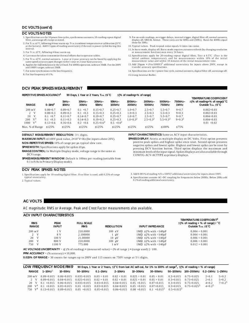
AC VOLTS
AC magnitude: RMS or Average. Peak and Crest Factor measurements also available.
ACV INPUT CHARACTERISTICSTEMPERATURE COEFFICIENT2
RMS PEAK FULL SCALE ±(% of reading + % of range) / °CRANGE INPUT RMS RESOLUTION INPUT IMPEDANCE Outside TCAL ±5°C
200 mV 1 V 210.0000 100 nV 1MΩ ±2% with <140pF 0.004 + 0.0012 V 8 V 2.100000 1 µV 1MΩ ±2% with <140pF 0.004 + 0.001
20 V 100 V 21.00000 10 µV 1MΩ ±2% with <140pF 0.006 + 0.001200 V 800 V 210.0000 100 µV 1MΩ ±2% with <140pF 0.006 + 0.001750 V 1100 V 775.000 1 mV 1MΩ ±2% with <140pF 0.012 + 0.001
AC VOLTAGE UNCERTAINTY = ±[ (% of reading) × (measured value) + (% of range ) × (range used) ] / 100.PPM ACCURACY = (% accuracy) × 10,000.0.015% OF RANGE = 30 counts for ranges up to 200V and 113 counts on 750V range at 51⁄2 digits.
LOW FREQUENCY MODE RMS1 90 Days, 1 Year or 2 Years, ±2°C from last AC self-cal, for 1% to 100% of range3, ±(% of reading + % of range)
RANGE 1–10Hz5 10–50Hz 50–100Hz 0.1–2kHz 2–10kHz 10–30kHz 30–50kHz 50–100kHz 100–200kHz 0.2–1MHz 1–2MHz
200 mV 0.09+0.015 0.06+0.015 0.035+0.015 0.03 + 0.01 0.02 + 0.01 0.025 + 0.01 0.05 + 0.01 0.3+0.015 0.75+0.025 2+0.1 5+0.22 V 0.09+0.015 0.04+0.015 0.025+0.015 0.02 + 0.01 0.02 + 0.01 0.025 + 0.01 0.05 + 0.01 0.3+0.015 0.75+0.025 2+0.1 5+0.2
20 V 0.1 +0.015 0.06+0.015 0.035+0.015 0.03+0.015 0.04+0.015 0.05 +0.015 0.07+0.015 0.3+0.015 0.75+0.025 4+0.2 7+0.25
200 V4 0.1 +0.015 0.05+0.015 0.03 +0.015 0.03+0.015 0.04+0.015 0.05 +0.015 0.07+0.015 0.3+0.015 0.75+0.0255 4+0.25
750 V4 0.13+0.015 0.09+0.015 0.05 +0.015 0.05+0.015 0.06+0.015 0.08 +0.015 0.1 +0.0155 0.5+0.0155
DC VOLTS (cont'd)
DC VOLTS NOTES1. Specifications are for 10 power line cycles, synchronous autozero, 10-reading repeat digital
filter, autorange off, except as noted.2. For TCAL ±1°C, following 4-hour warm-up. TCAL is ambient temperature at calibration (23°C
at the factory). Add 0.5 ppm of reading uncertainty if the unit is power cycled during thisinterval.
3. For TCAL ±5°C, following 4-hour warm-up.4. Care must be taken to minimize thermal offsets due to operator cables.5. For TCAL ±5°C, normal autozero. 1-year or 2-year accuracy can be found by applying the
same speed accuracy ppm changes to the 1-year or 2-year base accuracy.6. Applies for 1kΩ imbalance in the LO lead. For 400Hz operation, subtract 10dB. For the 200V
and 1000V ranges, subtract 20dB.7. For noise synchronous to the line frequency.8. For line frequency ± 0.1%.
9. For on-scale readings, no trigger delays, internal trigger, digital filter off, normal autozero,display off, SREAL format. These rates are for 60Hz and (50Hz). Rates for 400Hz equalthose for 50Hz.
10. Typical values. Peak-to-peak noise equals 6 times rms noise.11. In burst mode, display off. Burst mode requires autozero refresh (by changing resolution
or measurement function) once every 24 hours.12. Specifications apply for 20-reading repeat digital filter, TREF ± 0.5°C (TREF is the
initial ambient temperature), and for measurements within 10% of the initialmeasurement value and within 10 minutes of the initial measurement time.
13. Add 20ppm × (Vin/1000V)2 additional uncertainty for inputs above 200V, except intransfer accuracy specifications.
14. Specifications are for 1 power line cycle, normal autozero, digital filter off, autorange off.
15.Using Internal Buffer.
DCV PEAK SPIKES MEASUREMENT
REPETITIVE SPIKES ACCURACY1 90 Days, 1 Year or 2 Years, TCAL ±5°C ±(% of reading+% of range)TEMPERATURE COEFFICIENT
1kHz– 10kHz– 30kHz– 50kHz– 100kHz– 300kHz– 500kHz– 750kHz– ±(% of reading+% of range)/°CRANGE 0–1kHz4 10kHz 30kHz 50kHz 100kHz 300kHz 500kHz 750kHz 1MHz Outside TCAL ±5°C
200 mV 0.08+0.7 0.09+0.7 0.1 +0.7 0.15+0.7 0.25+0.7 1.0+0.7 2.5+0.7 5.5+0.7 9+0.7 0.002+0.032 V 0.08+0.3 0.09+0.3 0.1 +0.3 0.15+0.3 0.25+0.3 1.0+0.3 2.5+0.3 5.5+0.3 9+0.3 0.002+0.03
20 V 0.1 +0.7 0.11+0.7 0.14+0.7 0.19+0.7 0.25+0.7 1.0+0.7 2.5+0.7 5.5+0.7 9+0.7 0.004+0.03200 V3 0.1 +0.3 0.11+0.3 0.14+0.3 0.19+0.3 0.25+0.3 1.0+0.32 2.5+0.32 5.5+0.32 9+0.32 0.004+0.03
1000 V3 0.12+0.6 0.16+0.6 0.2 +0.6 0.25+0.62 0.5 +0.62 0.01 +0.02Max. % of Range ±125% ±125% ±125% ±125% ±125% ±125% ±125% ±100% ±75%
DEFAULT MEASUREMENT RESOLUTION: 31⁄2 digits.MAXIMUM INPUT: ±1100V peak value, 2×10⁷V•Hz (for inputs above 20V).NON-REPETITIVE SPIKES: 10% of range per µs typical slew rate.SPIKE WIDTH: Specifications apply for spikes ≥1µs.RANGE CONTROL: In Multiple Display mode, voltage range is the same as
DCV range.SPIKES MEASUREMENT WINDOW: Default is 100ms per reading (settable from
0.1 to 9.9s in Primary Display mode).
INPUT CHARACTERISTICS: Same as ACV input characteristics.SPIKES DISPLAY: Access as multiple display on DC Volts. First option presents
positive peak spikes and highest spike since reset. Second option presentsnegative spikes and lowest spike. Highest and lowest spike can be reset bypressing DCV function button. Third option displays the maximum andminimum levels of the input signal. Spikes displays are also available throughCONFIG-ACV-ACTYPE as primary displays.
DCV PEAK SPIKES NOTES1. Specifications apply for 10-reading digital filter. If no filter is used, add 0.25% of range
typical uncertainty.2. Typical values.
3. Add 0.001% of reading × (VIN/100V)2 additional uncertainty for inputs above 100V.4. Specifications assume AC+DC coupling for frequencies below 200Hz. Below 20Hz add
0.1% of reading additional uncertainty.

AC VOLTS (cont’d)
NORMAL MODE RMS1 90 Days, 1 Year or 2 Years, ±2°C from last AC self-cal for 1% to 100% of range3, ±(% of reading + % of range)
RANGE 20–50Hz 50–100Hz 0.1–2kHz 2–10kHz 10–30kHz 30–50kHz 50–100kHz 100–200kHz 0.2–1MHz 1–2MHz
200 mV 0.25+0.015 0.07+0.015 0.02 + 0.01 0.02 + 0.01 0.025 + 0.01 0.05 + 0.01 0.3+0.015 0.75+0.025 2+0.1 5+0.22 V 0.25+0.015 0.07+0.015 0.02 + 0.01 0.02 + 0.01 0.025 + 0.01 0.05 + 0.01 0.3+0.015 0.75+0.025 2+0.1 5+0.2
20 V 0.25+0.015 0.07+0.015 0.03+0.015 0.04+0.015 0.05 +0.015 0.07+0.015 0.3+0.015 0.75+0.025 4+0.2 7+0.25
200 V4 0.25+0.015 0.07+0.015 0.03+0.015 0.04+0.015 0.05 +0.015 0.07+0.015 0.3+0.015 0.75+0.0255 4+0.25
750 V4 0.25+0.015 0.1 +0.015 0.05+0.015 0.06+0.015 0.08 +0.015 0.1 +0.0155 0.5+0.0155
dB ACCURACY RMS ±dB, 90 Days, 1 Year or 2 Years, TCAL ±5°C, Reference=1V, Autoranging, Low Frequency Mode, AC+DC Coupling
INPUT 1–100Hz 0.1–30kHz 30–100kHz 100–200kHz 0.2–1MHz 1–2MHz
–54 to–40 dB (2 mV to 10 mV) 0.230 0.225 0.236 0.355–40 to–34 dB (10 mV to 20 mV) 0.036 0.031 0.041 0.088–34 to 6 dB (20 mV to 2 V) 0.023 0.018 0.028 0.066 0.265 0.630
6 to 26 dB (2 V to 20 V) 0.024 0.024 0.028 0.066 0.538 0.8205
26 to 46 dB (20 V to 200 V) 0.024 0.024 0.028 0.0665 0.5385
46 to 57.8 dB (200 V to 775 V) 0.018 0.021 0.0495
ACV READING RATES5,6
READINGS/SECOND WITHMEASUREMENT DEFAULT READINGS/SECOND TO MEMORY READINGS/SECOND TO IEEE-48812 TIME STAMP TO IEEE-48812
PLC APERTURE BITS DIGITS Autozero Off Autozero On Autozero Off Autozero On Autozero Off Autozero On
10 167 ms (200 ms) 29 61⁄2 6 ( 5 ) 2 (1.7) 6 ( 5 ) 2 (1.6) 6 ( 5 ) 2 (1.6)2 33.4 ms (40 ms) 27 51⁄2 29 (25) 9 (7.6) 28 (23) 9 (7.4) 26 (21) 9 (7.4)1 16.7 ms (20 ms) 26 51⁄2 56 (48) 47 (40) 52 (43) 44 (36) 48 (39) 40 (33)0.2 3.34 ms (4 ms) 23 51⁄2 145 (129) 110 (98) 131 (117) 100 (88) 102 (91) 79 (70)0.1 1.67 ms (2 ms) 22 51⁄2 150 (144) 112 (108) 132 (127) 101 (97) 102 (98) 80 (77)0.02 334 µs (400 µs) 20 51⁄2 150 (150) 115 (115) 132 (132) 103 (103) 102 (102) 80 (80)0.01 167 µs (167 µs) 19 41⁄2 382 (382) 116 (116) 251 (251) 103 (103) 163 (163) 80 (80)0.018 167 µs (167 µs) 19 41⁄2 2000 (2000) 2000 (2000)
ACV CREST FACTOR MEASUREMENT11
CREST FACTOR = Peak AC / rms AC.CREST FACTOR RESOLUTION: 3 digits.CREST FACTOR ACCURACY: Peak AC uncertainty + AC normal mode rms
uncertainty.MEASUREMENT TIME: 100ms plus rms measurement time.INPUT CHARACTERISTICS: Same as ACV input.CREST FACTOR FREQUENCY RANGE: 20Hz – 1MHz.CREST FACTOR DISPLAY: Access as multiple display on AC volts.
AC COUPLING: For AC only coupling, add the following % of reading:
1–10Hz 10–20Hz 20–50Hz 50–100Hz 100–200HzNormal Mode
(rms, average) — — 0.41 0.07 0.015
Low Frequency Mode(rms) 0.1 0.01 0 0 0
For low frequency mode below 200Hz, specifications apply for sine wave inputs only.
AC+DC COUPLING: For DC>20% of AC rms voltage, apply the followingadditional uncertainty, multiplied by the ratio (DC/total rms). Applies to rmsand average measurements.
RANGE % of Reading % of Range
200mV, 20V 0.05 0.12V, 200V, 750V 0.07 0.01
HIGH CREST FACTOR ADDITIONAL ERROR ±(% of reading)
Applies to rms measurements.
CREST FACTOR: 1 – 2 2 – 3 3 – 4 4 – 5ADDITIONAL ERROR: 0 0.1 0.2 0.4
AVERAGE ACV MEASUREMENTNormal mode rms specifications apply from 10% to 100% of range, for 20Hz–1MHz. Add 0.025% of range uncertainty for 50kHz–100kHz, 0.05% of rangeuncertainty for 100kHz–200kHz, and 0.5% of range uncertainty for 200kHz–1MHz.
ACV PEAK VALUE MEASUREMENT10 REPETITIVE PEAK ACCURACY, ±(% of reading+% of range), 90 Days, 1 Year or 2 Years, TCAL ±5°CTEMPERATURE COEFFICIENT
20Hz– 1kHz– 10kHz– 30kHz– 50kHz– 100kHz– 300kHz– 500kHz– 750kHz– ±(% of reading+% of range)/°CRANGE 1kHz9 10kHz 30kHz 50kHz 100kHz 300kHz 500kHz 750kHz 1MHz Outside TCAL ±5°C
200 mV 0.08+0.7 0.09+0.7 0 .1 +0.7 0.15+0.7 0.25+0.7 1.0+0.7 2.5+0.7 5.5+0.7 9+0.7 0.002 + 0.032 V 0.08+0.3 0.09+0.3 0 .1 +0.3 0.15+0.3 0.25+0.3 1.0+0.3 2.5+0.3 5.5+0.3 9+0.3 0.002 + 0.03
20 V 0.1 +0.7 0.11+0.7 0.14+0.7 0.19+0.7 0.25+0.7 1.0+0.7 2.5+0.7 5.5+0.7 9+0.7 0.004 + 0.03200 V 4 0.1 +0.3 0.11+0.3 0.14+0.3 0.19+0.3 0.25+0.3 1.0+0.35 2.5+0.35 5.5+0.35 9+0.35 0.004 + 0.03750 V 4 0.12+0.6 0.16+0.6 0.2 +0.6 0.25+0.65 0.5 +0.65 0.01 + 0.02
Valid % of Range7 10–400% 10–400% 10–400% 10–350% 10–350% 10–250% 10–150% 10–100% 7.5–75%
PEAK MEASUREMENT WINDOW: 100ms per reading.MAXIMUM INPUT: ±1100V peak, 2×10⁷V•Hz (for inputs above 20V).
DEFAULT MEASUREMENT RESOLUTION: 4 digits.NON-REPETITIVE PEAK: 10% of range per µs typical slew rate for single spikes.PEAK WIDTH: Specifications apply for all peaks ≥1µs.

AC VOLTS NOTES1. Specifications apply for sinewave input, AC + DC coupling, 1 power line cycle, autozero on,
digital filter off, following 55-minute warm-up.2. Temperature coefficient applies to rms and average readings. For frequencies above 100kHz,
add 0.01% of reading/°C to temperature coefficient.3. For 1% to 5% of range below 750V range, and for 1% to 7% of 750V range, add 0.01% of
range uncertainty. For inputs from 200kHz to 2MHz, specifications apply above 10% ofrange.
4. Add 0.001% of reading × (VIN/100V)2 additional uncertainty above 100V rms.5. Typical values.6. For on-scale readings, no trigger delays, internal trigger, digital filter off, normal autozero,
display off, SREAL format. These rates are for 60Hz and (50Hz). Rates for 400Hz equal
those for 50Hz. Applies for normal rms and average mode. Low frequency rms mode rateis typically 0.2 readings per second.
7. For overrange readings 200–300% of range, add 0.1% of reading uncertainty. For 300–400%of range, add 0.2% of reading uncertainty.
8. In burst mode, display off. Burst mode requires autozero refresh (by changing resolution ormeasurement function) once every 24 hours.
9. AC peak specifications assume AC + DC coupling for frequencies below 200Hz.10. Specifications apply for 10-reading digital filter. If no filter is used, add 0.25% of range
typical uncertainty.11. Subject to peak input voltage specification.
SPEED AND ACCURACY 90 DaysACCURACY9,15
±(ppm of reading+ppm of range+ppm of range rms noise12)10PLC 1PLC,
DFILT On, 10PLC DFILT On, 1PLC 0.1PLC11 0.01PLC 8,11
RANGE 10 Readings DFILT Off 10 Readings DFILT Off DFILT Off DFILT Off
20 Ω 15 + 11 + 0 15 + 11 + 0.5 15 + 13 + 0.5 15 + 13 + 1 15 + 16 + 25 110 + 200 + 35200 Ω 15 + 8 + 0 15 + 8 + 0.5 17 + 8 + 0.5 17 + 8 + 1 17 + 10 + 15 110 + 200 + 35
2 kΩ 7 + 0.8 + 0 7 + 0.8 + 0.05 8 + 0.8 + 0.07 8 + 0.8 + 0.2 8 + 1 + 2 130 + 230 + 520 kΩ 7 + 0.8 + 0 7 + 0.8 + 0.1 8 + 0.8 + 0.1 9 + 0.8 + 0.2 40 + 1 + 2 130 + 230 + 5
200 kΩ 29 + 0.8 + 0 29 + 0.8 + 0.1 31 + 0.8 + 0.1 34 + 0.8 + 0.2 250 + 1 + 22 MΩ 53 + 0.5 + 0 55 + 0.5 + 0.1 58 + 0.5 + 0.1 68 + 0.5 + 0.2 750 + 0.7 + 2
20 MΩ 4 175 + 0.6 + 0 175 + 0.6 + 0 175 + 0.6 + 0 200 + 0.6 + 0200 MΩ 4 500 + 3 + 0 510 + 3 + 0 510 + 3 + 0 550 + 3 + 0
1 GΩ 4 2000 + 15 + 0 2100 + 15 + 0 2100 + 15 + 0 2500 + 15 + 0
PLC = Power Line Cycles. DFILT = Digital Filter.
SETTLING CHARACTERISTICS:Normal Mode (rms, avg.) <300ms to 1% of step change
<450ms to 0.1% of step change<500ms to 0.01% of step change
Low Frequency Mode (rms) <5s to 0.1% of final value
COMMON MODE REJECTION: For 1kΩ imbalance in either lead: >60dB for linefrequency ±0.1%.
MAXIMUM VOLT•Hz PRODUCT: 2 × 10⁷V•Hz (for inputs above 20V).AUTORANGING: Autoranges up at 105% of range, down at 10% of range.
AC VOLTS (cont’d)
KEITHLEY FACTORY CALIBRATIONUNCERTAINTY
RANGE ppm of reading
20 Ω 29.5200 Ω 7.7
2 kΩ 6.420 kΩ 7.8
200 kΩ 7.32MΩ 14.9
20MΩ 14.9200MΩ 14.9
1 GΩ 14.9Factory calibration uncertainty represents traceabilityto NIST. This uncertainty is added to relative accuracyspecifications to obtain absolute accuracies. The20Ω - 2MΩ range uncertainties are equal to theuncertainty of the respective calibration sources. The20MΩ, 200MΩ, and 1GΩ range uncertainties are equalto the uncertainty of the 2MΩ calibration source.
MAXIMUM MAXIMUM MAXIMUMFULL CURRENT OPEN HI LEAD LO LEAD OFFSET
RANGE SCALE RESOLUTION SOURCE1 CIRCUIT12 RESISTANCE2 RESISTANCE2 COMPENSATION3
20 Ω 21.0000000 100 nΩ 7.2 mA 5 V 50 Ω 10 Ω ±0.2 V200 Ω 210.000000 1 µΩ 960 µA 5 V 200 Ω 100 Ω ±0.2 V
2 kΩ 2100.00000 10 µΩ 960 µA 5 V 200 Ω 150 Ω -0.2 V to +2 V20 kΩ 21.0000000 100 µΩ 96 µA 5 V 1.5 kΩ 1.5 kΩ -0.2 V to +2 V
200 kΩ 210.000000 1 mΩ 9.6 µA 5 V 1.5 kΩ 1.5 kΩ2 MΩ 2.10000000 10 mΩ 1.9 µA 6 V 1.5 kΩ 1.5 kΩ
20 MΩ 4 21.0000000 100 mΩ 1.4 µA 13 14 V200 MΩ 4 210.000000 1 Ω 1.4 µA 13 14 V
1 GΩ 4 1.05000000 10 Ω 1.4 µA 13 14 V
OHMS
TWO-WIRE AND FOUR-WIRE OHMS
ENHANCED ACCURACY5 - 10PLC, Offset comp. on, DFILT 10TEMPERATURECOEFFICIENT
RELATIVE ACCURACY ± (ppm of reading +± (ppm of reading + ppm of range) ppm of range) / °C
RANGE Transfer14 24 Hours6 90 Days7 1 Year7 2 Years7 Outside TCAL ±5°C20 Ω 2.5 + 3 5 + 4.5 15 + 6 17 + 6 20 + 6 2.5 + 0.7
200 Ω 2.5 + 2 5 + 3 15 + 4 17 + 4 20 + 4 2.5 + 0.52 kΩ 1.3 + 0.2 2.5 + 0.3 7 + 0.4 9 + 0.4 11 + 0.4 0.8 + 0.05
20 kΩ 1.3 + 0.2 2.5 + 0.3 7 + 0.4 9 + 0.4 11 + 0.4 0.8 + 0.05200 kΩ 2.5 + 0.4 5.5 + 0.5 29 + 0.8 35 + 0.9 40 + 1 3.5 + 0.18
2 MΩ 5 + 0.2 12 + 0.3 53 + 0.5 65 + 0.5 75 + 0.5 7 + 0.120 MΩ 4 15 + 0.1 50 + 0.2 175 + 0.6 250 + 0.6 300 + 0.6 20 + 0.1
200 MΩ 4 50 + 0.5 150 + 1 500 + 3 550 + 3 600 + 3 80 + 0.51 GΩ 4 250 + 2.5 750 + 5 2000 + 15 2050 + 15 2100 + 15 400 + 2.5
RESISTANCE UNCERTAINTY = ± [ (ppm of reading) × (measured value) + (ppm of range)× (range used) ] / 1,000,000.
% ACCURACY = (ppm accuracy) / 10,000.1PPM OF RANGE = 20 counts for ranges up to 200MΩ and 10 counts on 1GΩ range at 71⁄2 digits.
12.Using Internal Buffer.
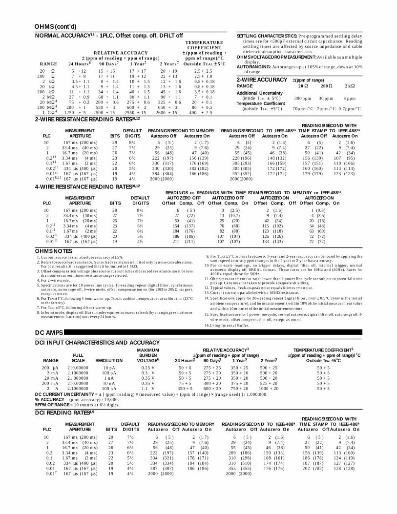
NORMAL ACCURACY15 - 1PLC, Offset comp. off, DFILT offTEMPERATURECOEFFICIENT
RELATIVE ACCURACY ± (ppm of reading +± (ppm of reading + ppm of range) ppm of range)/°C
RANGE 24 Hours6 90 Days7 1 Year7 2 Years7 Outside TCAL ± 5°C
20 Ω 5 +12 15 + 16 17 + 17 20 + 19 2.5 + 2.5200 Ω 7 + 8 17 + 11 19 + 12 22 + 13 2.5 + 1.8
2 kΩ 3.5 + 1.1 8 + 1.4 10 + 1.5 12 + 1.6 0.8 + 0.1820 kΩ 4.5 + 1.1 9 + 1.4 11 + 1.5 13 + 1.6 0.8 + 0.18
200 kΩ 11 + 1.1 34 + 1.4 40 + 1.5 45 + 1.6 3.5 + 0.182 MΩ 27 + 0.9 68 + 1.1 80 + 1.1 90 + 1.1 7 + 0.1
20 MΩ 4 75 + 0.2 200 + 0.6 275 + 0.6 325 + 0.6 20 + 0.1200 MΩ 4 200 + 1 550 + 3 600 + 3 650 + 3 80 + 0.5
1 GΩ 4 1250 + 5 2500 + 15 2550 + 15 2600 + 15 400 + 2.5
DC AMPS
DCI INPUT CHARACTERISTICS AND ACCURACYMAXIMUM RELATIVE ACCURACY1 TEMPERATURE COEFFICIENT1
FULL BURDEN ±(ppm of reading + ppm of range) ±(ppm of reading + ppm of range)/°CRANGE SCALE RESOLUTION VOLTAGE6 24 Hours2 90 Days3 1 Year3 2 Years3 Outside TCAL ±5°C
200 µA 210.00000 10 pA 0.25 V 50 + 6 275 + 25 350 + 25 500 + 25 50 + 52 mA 2.1000000 100 pA 0.3 V 50 + 5 275 + 20 350 + 20 500 + 20 50 + 5
20 mA 21.000000 1 nA 0.35 V 50 + 5 275 + 20 350 + 20 500 + 20 50 + 5200 mA 210.00000 10 nA 0.35 V 75 + 5 300 + 20 375 + 20 525 + 20 50 + 5
2 A 2.1000000 100 nA 1.1 V 350 + 5 600 + 20 750 + 20 1000 + 20 50 + 5DC CURRENT UNCERTAINTY = ± [ (ppm reading) × (measured value) + (ppm of range) × (range used) ] / 1,000,000.% ACCURACY = (ppm accuracy) / 10,000.5PPM OF RANGE = 10 counts at 61⁄2 digits.
DCI READING RATES4,5
READINGS/SECOND WITHMEASUREMENT DEFAULT READINGS/SECOND TO MEMORY READINGS/SECOND TO IEEE-4889 TIME STAMP TO IEEE-4889
PLC APERTURE B I T S DIGITS Autozero Off Autozero On Autozero Off Autozero On Autozero Off Autozero On
10 167 ms (200 ms) 29 71⁄2 6 ( 5 ) 2 (1.7) 6 ( 5 ) 2 (1.6) 6 ( 5 ) 2 (1.6)2 33.4 ms (40 ms) 27 71⁄2 29 (25) 9 (7.6) 29 (24) 9 (7.4) 27 (22) 9 (7.4)1 16.7 ms (20 ms) 26 61⁄2 56 (48) 47 (40) 55 (45) 46 (38) 50 (41) 42 (34)0.2 3.34 ms (4 ms) 23 61⁄2 222 (197) 157 (140) 209 (186) 150 (133) 156 (139) 113 (100)0.1 1.67 ms (2 ms) 22 51⁄2 334 (321) 178 (171) 310 (298) 168 (161) 186 (178) 124 (119)0.02 334 µs (400 µs) 20 51⁄2 334 (334) 184 (184) 310 (310) 174 (174) 187 (187) 127 (127)0.01 167 µs (167 µs) 19 41⁄2 387 (387) 186 (186) 355 (355) 176 (176) 202 (202) 128 (128)0.017 167 µs (167 µs) 19 41⁄2 2000 (2000) 2000 (2000)
2-WIRE RESISTANCE READING RATES10,12
READINGS/SECOND WITHMEASUREMENT DEFAULT READINGS/SECOND TO MEMORY READINGS/SECOND TO IEEE-48816 TIME STAMP TO IEEE-48816
PLC APERTURE BITS DIGITS Autozero Off Autozero On Autozero Off Autozero On Autozero Off Autozero On10 167 ms (200 ms) 29 81⁄2 6 ( 5 ) 2 (1.7) 6 (5) 2 (1.6) 6 (5) 2 (1.6)
2 33.4 ms (40 ms) 27 71⁄2 29 (25) 9 (7.6) 29 (24) 9 (7.4) 27 (22) 9 (7.4)1 16.7 ms (20 ms) 26 71⁄2 56 (48) 47 (40) 55 (45) 46 (38) 50 (41) 42 (34)0.211 3.34 ms (4 ms) 23 61⁄2 222 (197) 156 (139) 220 (196) 148 (132) 156 (139) 107 (95)0.111 1.67 ms (2 ms) 22 61⁄2 330 (317) 176 (169) 305 (293) 166 (159) 157 (151) 110 (106)0.0211 334 µs (400 µs) 20 51⁄2 330 (330) 182 (182) 305 (305) 172 (172) 160 (160) 113 (113)0.0111 167 µs (167 µs) 19 41⁄2 384 (384) 186 (186) 352 (352) 172 (172) 179 (179) 123 (123)0.018,11 167 µs (167 µs) 19 41⁄2 2000 (2000) 2000(2000)
4-WIRE RESISTANCE READING RATES10,12
READINGS or READINGS WITH TIME STAMP/SECOND TO MEMORY or IEEE-48816
MEASUREMENT DEFAULT AUTOZERO OFF AUTOZERO OFF AUTOZERO ON AUTOZERO ONPLC APERTURE B I T S DIGITS Offset Comp. Off Offset Comp. On Offset Comp. Off Offset Comp. On
10 167 ms (200 ms) 29 81⁄2 6 ( 5 ) 3 (2.5) 2 (1.6) 1 (0.8)2 33.4 ms (40 ms) 27 71⁄2 27 (22) 13 (10.7) 9 (7.4) 4 (3.5)1 16.7 ms (20 ms) 26 71⁄2 50 (41) 25 (20) 42 (34) 20 (16)0.211 3.34 ms (4 ms) 23 61⁄2 154 (137) 76 (68) 115 (102) 54 (48)0.111 1.67 ms (2 ms) 22 61⁄2 184 (176) 92 (88) 123 (118) 63 (60)0.0211 334 µs (400 µs) 20 51⁄2 186 (186) 107 (107) 126 (126) 72 (72)0.0111 167 µs (167 µs) 19 41⁄2 211 (211) 107 (107) 133 (133) 72 (72)
OHMS NOTES1. Current source has an absolute accuracy of ± 5%.2. Refers to source lead resistance. Sense lead resistance is limited only by noise considerations.
For best results, it is suggested that it be limited to 1.5kΩ.3. Offset compensation voltage plus source current times measured resistance must be less
than source current times resistance range selected.4. For 2-wire mode.5. Specifications are for 10 power line cycles, 10-reading repeat digital filter, synchronous
autozero, autorange off, 4-wire mode, offset compensation on (for 20Ω to 20kΩ ranges),except as noted.
6. For TCAL ±1°C, following 4-hour warm-up. TCAL is ambient temperature at calibration (23°Cat the factory).
7. For TCAL ±5°C, following 4-hour warm-up.8. In burst mode, display off. Burst mode requires autozero refresh (by changing resolution or
measurement function) once every 24 hours.
9. For TCAL ±5°C, normal autozero. 1-year and 2-year accuracy can be found by applying thesame speed accuracy ppm changes to the 1-year or 2-year base accuracy.
10. For on-scale readings, no trigger delays, digital filter off, internal trigger, normalautozero, display off, SREAL format. These rates are for 60Hz and (50Hz). Rates for400Hz equal those for 50Hz.
11. Ohms measurements at rates lower than 1 power line cycle are subject to potential noisepickup. Care must be taken to provide adequate shielding.
12. Typical values. Peak-to-peak noise equals 6 times rms noise.13. Current source is paralleled with a 10MΩ resistance.14. Specifications apply for 20-reading repeat digital filter, TREF ± 0.5°C (TREF is the initial
ambient temperature), and for measurements within 10% of the initial measurement valueand within 10 minutes of the initial measurement time.
15. Specifications are for 1 power line cycle, normal autozero, digital filter off, autorange off, 4-wire mode, offset compensation off, except as noted.
16.Using Internal Buffer.
OHMS (cont’d)
2-WIRE ACCURACY ±(ppm of range)RANGE 20 Ω 200 Ω 2 kΩAdditional Uncertainty
(inside TCAL ± 5°C) 300 ppm 30 ppm 3 ppmTemperature Coefficient
(outside TCAL ±5°C) 70ppm/°C 7ppm/°C 0.7ppm/°C
SETTLING CHARACTERISTICS: Pre-programmed settling delaytimes are for <500pF external circuit capacitance. Readingsettling times are affected by source impedance and cabledielectric absorption characteristics.
OHMS VOLTAGE DROP MEASUREMENT: Available as a multipledisplay.
AUTORANGING: Autoranges up at 105% of range, down at 10%of range.

KEITHLEY FACTORY CALIBRATION UNCERTAINTYRANGE ppm of reading
200 µA 432 mA 40
20 mA 55200 mA 162
2 A 129
Factory calibration uncertainty represents traceability to NIST. This uncertaintyis added to relative accuracy specifications to obtain absolute accuracies. Theuncertainties for each range are equal to the uncertainty of the respective calibrationsources.
SETTLING CHARACTERISTICS: <500µs to 50ppm of step size. Reading settlingtimes are affected by source impedance and cable dielectric absorptioncharacteristics.
MAXIMUM ALLOWABLE INPUT: 2.1A, 250V.
OVERLOAD PROTECTION: 2A fuse (250V), accessible from front (for front input)and rear (for rear input).
AUTORANGING: Autoranges up at 105% of range, down at 10% of range.
DC AMPS NOTES1. Specifications are for 1 power line cycle, autozero on, 10-reading repeat digital filter.2. For TCAL ± 1°C, following 55-minute warm-up. TCAL is ambient temperature at calibration
(23°C at the factory).3. For TCAL ± 5°C, following 55-minute warm-up.4. Typical values. Peak-to-peak noise equals 6 times rms noise.5. For on-scale readings, no trigger delays, internal trigger, digital filter off, normal autozero,
display off, SREAL format. These rates are for 60Hz and (50Hz). Rates for 400Hz equal thosefor 50Hz.
6. Actual maximum burden voltage = (maximum burden voltage) × (I MEASURED/I FULL SCALE).7. In burst mode, display off. Burst mode requires autozero refresh (by changing resolution
or measurement function) once every 24 hours.8. For TCAL ±5°C, normal autozero. 1-year and 2-year accuracy can be found by applying the
same speed accuracy ppm changes to the 1-year or 2-year base accuracy.9.Using Internal Buffer.
DC IN-CIRCUIT CURRENTThe DC in-circuit current measurement function allows a user to measure thecurrent through a wire or a circuit board trace without breaking the circuit.When the In-Circuit Current Measurement function is selected, the 2002 will firstperform a 4-wire resistance measurement, then a voltage measurement, and willdisplay the calculated current.TYPICAL RANGES:
Current: 100µA to 12A.Trace Resistance: 1mΩ to 10Ω.Voltage: ±200mV max. across trace.Speed: 4 measurements/second at 1 power line cycle.Accuracy: ±(5% + 500µA). For 1 power line cycle, autozero on, 10-
reading digital filter, TCAL±5°C, 90 days, 1 year or 2 years.
MEASUREMENT RANGE CHART
10Ω
1Ω
100mΩ
10mΩ
1mΩ
1mA 10mA 100mA 1A 10A 100A100µA
Measured Current
Trace Resistance
Specified Measurement
Range
SPEED AND ACCURACY 90 DaysACCURACY1,8
±(ppm of reading+ppm of range+ppm of range rms noise4)1PLC
DFILT On, 1PLC 0.1PLC 0.01PLC 7
RANGE 10 Readings DFILT Off DFILT Off DFILT Off200 µA 275+25+0 275+25+0.5 300+25+50 300+200+80
2 mA 275+20+0 275+20+0.5 300+20+50 300+200+8020 mA 275+20+0 275+20+0.5 300+20+50 300+200+80
200 mA 300+20+0 300+20+0.5 325+20+50 325+200+802 A 600+20+0 600+20+0.5 625+20+50 625+200+80
PLC = Power Line Cycles. DFILT = Digital Filter.
DC AMPS (cont’d)
AC AMPS
AC magnitude: RMS or Average.
ACI INPUT CHARACTERISTICSTEMPERATURE
MAXIMUM COEFFICIENTRMS PEAK FULL SCALE BURDEN ±(% of reading + % of range)/°C
RANGE INPUT RMS RESOLUTION VOLTAGE5 Outside TCAL ±5°C200 µA 1 mA 210.0000 100 pA 0.35 V 0.01 + 0.001
2 mA 10 mA 2.100000 1 nA 0.45 V 0.01 + 0.00120 mA 100 mA 21.00000 10 nA 0.5 V 0.01 + 0.001
200 mA 1 A 210.0000 100 nA 0.5 V 0.01 + 0.0012 A 2 A 2.100000 1 µA 1.5 V 0.01 + 0.001
ACI ACCURACY1,2 90 Days, 1 Year or 2 Years, TCAL ±5°C, for 5% to 100% of range, ±(% of reading + % of range)
RANGE 20Hz–50Hz 50Hz–200Hz 200Hz–1kHz 1kHz–10kHz 10kHz–30kHz3 30kHz–50kHz3 50kHz–100kHz3
200 µA 0.35 + 0.015 0.2 + 0.015 0.4 + 0.015 0.5 + 0.0152 mA 0.3 + 0.015 0.15 + 0.015 0.12 + 0.015 0.12 + 0.015 0.25 + 0.015 0.3 + 0.015 0.5 + 0.015
20 mA 0.3 + 0.015 0.15 + 0.015 0.12 + 0.015 0.12 + 0.015 0.25 + 0.015 0.3 + 0.015 0.5 + 0.015200 mA 0.3 + 0.015 0.15 + 0.015 0.12 + 0.015 0.15 + 0.015 0.5 + 0.015 1 + 0.015 3 + 0.015
2 A 0.35 + 0.015 0.2 + 0.015 0.3 + 0.015 0.45 + 0.015 1.5 + 0.015 4 + 0.015
AC CURRENT UNCERTAINTY = ±[ (% of reading) × (measured value) + (% of range) × (range used) ] / 100.PPM ACCURACY = (% accuracy) × 10,000.0.015% OF RANGE = 30 counts at 51⁄2 digits.
AC COUPLING: For AC only coupling, add the following % of reading:
20–50Hz 50–100Hz 100–200Hzrms, Average 0.55 0.09 0.015
AC+DC COUPLING: For DC>20% of AC rms voltage, apply the followingadditional uncertainty, multiplied by the ratio (DC/total rms).
% of Reading % of Rangerms, Average 0.05 0.1

TEMPERATURE (RTD)RESO- 4-WIRE ACCURACY5
RANGE LUTION 24 Hours2 90 Days3 1 Year3 2 Years3
–100° to +100°C 0.001°C ±0.016°C ±0.020°C ±0.021°C ±0.022°C–200° to +630°C 0.001°C ±0.061°C ±0.066°C ±0.068°C ±0.070°C–148° to +212°F 0.001°F ±0.029°F ±0.036°F ±0.038°F ±0.040°F–328° to +1166°F 0.001°F ±0.110°F ±0.119°F ±0.122°F ±0.126°F
RTD TYPE: 100Ω platinum, DIN 43760, 4-wire. ITS-90 (PT100, D100, F100) andIPTS-68 (PT385, PT3916).
SENSOR CURRENT: 960µA (pulsed).TEMPERATURE COEFFICIENT: ± 0.001°C/°C or ± 0.002°F/°C outside TCAL ±5°C.MAXIMUM SOURCE HI LEAD RESISTANCE: 200Ω..MAXIMUM SOURCE LO LEAD RESISTANCE: 100Ω.
RTD TEMPERATURE READING RATES1 (2- or 4-Wire)READINGS or READINGS WITH TIME STAMP/SECOND
TO MEMORY or IEEE-488PLC Autozero Off Autozero On
10 3 (2.5) 1 (0.8)2 12 (10) 4 (3.3)1 20 (16) 17 (13)0.1 51 (49) 41 (39)0.01 58 (58) 46 (46)
1. For on-scale readings, no trigger delays, digital filter off, display off, normal autozero,internal trigger, SREAL format. These rates are for 60Hz and (50Hz). Rates for 400Hz equalthose for 50Hz. Typical values.
2. For TCAL ± 1°C, following 4-hour warm-up.3. For TCAL ± 5°C, following 4-hour warm-up.
4. Relative to external 0°C reference junction; exclusive of thermocouple errors. Junctiontemperature may be external. Applies for 90 days, 1 year or 2 years, TCAL ±5°C.
5. Specifications are for 10 power line cycles, autozero on, 10 reading repeat digitalfilter, 4-wire mode. Exclusive of rtd probe errors.
6.Using Internal Buffer.
TEMPERATURE NOTES
AC AMPS (cont’d)ACI READING RATES3,4
READINGS/SECOND WITHMEASUREMENT DEFAULT READINGS/SECOND TO MEMORY READINGS/SECOND TO IEEE-4887 TIME STAMP TO IEEE-4887
PLC APERTURE BITS DIGITS Autozero Off Autozero On Autozero Off Autozero On Autozero Off Autozero On
10 167 ms (200 ms) 29 61⁄2 6 ( 5 ) 2 (1.7) 6 ( 5 ) 2 (1.6) 6 ( 5 ) 2 (1.6)2 33.4 ms (40 ms) 27 51⁄2 29 (25) 9 (7.6) 28 (23) 9 (7.4) 27 (22) 9 (7.4)1 16.7 ms (20 ms) 26 51⁄2 56 (48) 47 (40) 53 (43) 44 (36) 47 (38) 40 (33)0.2 3.34 ms (4 ms) 23 51⁄2 163 (145) 102 (91) 139 (124) 100 (89) 95 (84) 74 (66)0.1 1.67 ms (2 ms) 22 51⁄2 163 (156) 104 (100) 139 (133) 101 (97) 95 (91) 75 (72)0.02 334 µs (400 µs) 20 51⁄2 163 (163) 107 (107) 139 (139) 103 (103) 95 (95) 76 (76)0.01 167 µs (167 µs) 19 41⁄2 384 (384) 110 (110) 253 (253) 103 (103) 164 (164) 76 (76)0.016 167 µs (167 µs) 19 41⁄2 2000 (2000) 2000 (2000)
SETTLING CHARACTERISTICS: <300ms to 1% of step change<450ms to 0.1% of step change<500ms to 0.01% of step change
AUTORANGING: Autoranges up at 105% of range, down at 10% of range.
AVERAGE ACI MEASUREMENTRms specifications apply for 10% to 100% of range.
HIGH CREST FACTOR ADDITIONAL ERROR ±(% of reading)
Applies to rms measurements.
CREST FACTOR 1 – 2 2 – 3 3 – 4 4 – 5ADDITIONAL ERROR 0 0.1 0.2 0.4
AC AMPS NOTES1. Specifications apply for sinewave input, AC+DC coupling, 1 power line cycle, autozero on,
digital filter off, following 55-minute warm-up.2. Add 0.005% of range uncertainty for current above 0.5A rms for self-heating.3. Typical values.4. For on-scale readings, no trigger delays, digital filter off, normal autozero, display off,
internal trigger, SREAL format. These rates are for 60Hz and (50Hz). Rates for 400Hz equalthose for 50Hz.
5. Actual maximum burden voltage = (maximum burden voltage) × (IMEASURED/IFULL SCALE).6. In burst mode, display off. Burst mode requires autozero refresh (by changing resolution or
measurement function) once every 24 hours.
TIME BASE: 7.68MHz ± 0.01%, 0°C to 55°C.READING TIME: 420ms maximum.VOLTAGE INPUT IMPEDANCE: 1MΩ ±2% with <140pF.
TRIGGER LEVEL ADJUSTMENT: Trigger level is adjustable in 0.5% of range stepsto ±60% of range in real-time using the up and down range buttons.
FREQUENCY RANGING: Autoranging from Hz to MHz.FREQUENCY COUPLING: AC + DC or AC only.
FREQUENCY COUNTER
FREQUENCY/PERIOD INPUT CHARACTERISTICS AND ACCURACY 90 Days, 1 Year or 2 Years
FREQUENCY PERIOD MINIMUM SIGNAL LEVEL2 MAXIMUM TRIGGER ACCURACYRANGE1 RANGE RESOLUTION 1Hz–1MHz 1–5MHz 5–15MHz INPUT LEVEL ±(% of reading)
AC Voltage Input 1Hz–15 MHz 67 ns – 1 s 5 digits 60 mV 60 mV 350 mV 1100 V pk1 0–600V 0.03AC Current Input 1Hz– 1 MHz 1 µs – 1 s 5 digits 150 µA 1 A pk 0–600mA 0.03
FREQUENCY NOTES 1. Subject to 2 × 10⁷V•Hz product (for inputs above 20V). 2 Valid for the lowest range. For each range increase, multiply these numbers by 10.
7.Using Internal Buffer.
TEMPERATURE (Thermocouple)THERMO-COUPLE
TYPE RANGE RESOLUTION ACCURACY4
J –200° to + 760°C 0.001°C ±0.5°CK –200° to +1372°C 0.001°C ±0.5°CT –200° to + 400°C 0.001°C ±0.5°CE –200° to +1000°C 0.001°C ±0.6°CR 0° to +1768°C 0.001°C ±3 °CS 0° to +1768°C 0.001°C ±3 °CB +350° to +1820°C 0.001°C ±5 °C
TC TEMPERATURE READING RATES1
READINGS/SECONDREADINGS/SECOND READINGS/SECOND WITH TIME STAMP
TO MEMORY TO IEEE-4886 TO IEEE-4886
Autozero Autozero AutozeroPLC Off On Off On Off On
10 6 ( 5 ) 2 (1.7) 6 ( 5 ) 2 (1.6) 6 ( 5 ) 2 (1.6)2 29 (25) 9 (7.6) 29 (24) 9 (7.4) 27 (22) 9 (7.4)1 57 (48) 47 (40) 56 (46) 46 (38) 50 (41) 42 (34)0.1 131 (126) 107 (103) 100 (96) 84 (81) 83 (80) 72 (69)0.01 168 (168) 112 (112) 121 (121) 89 (89) 96 (96) 74 (74)
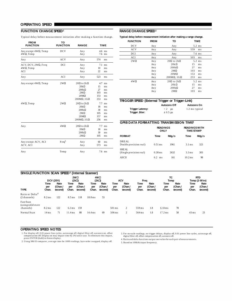
OPERATING SPEED
RANGE CHANGE SPEED1
Typical delay before measurement initiation after making a range change.
FUNCTION FROM TO TIME
DCV Any Any 5.2 msACV Any Any 559 ms
DCI Any Any 7.6 msACI Any Any 503 ms2WΩ Any 20Ω to 2kΩ 5.2 ms
Any 20kΩ 15 msAny 200kΩ 27 msAny 2MΩ 103 msAny 20MΩ 153 msAny 200MΩ, 1GΩ 253 ms
4WΩ Any 20Ω to 2kΩ 5.2 msAny 20kΩ 15 msAny 200kΩ 27 msAny 2MΩ 103 ms
SINGLE FUNCTION SCAN SPEED3 (Internal Scanner)2WΩ 4WΩ TC RTD
DCV (20V) (2kΩ) (2kΩ) ACV Freq Temp Temp (2-Wire)Time Rate Time Rate Time Rate Time Rate Time Rate Time Rate Time Rateper (Chan./ per (Chan./ per (Chan./ per (Chan./ per (Chan./ per (Chan./ per (Chan./
TYPE Chan. second) Chan. second) Chan. second) Chan. second) Chan. second) Chan. second) Chan. second)
Ratio or Delta4
(2 channels) 8.2 ms 122 8.5 ms 118 18.8 ms 53
Fast Scan(using solid state channels) 8.2 ms 122 6.3 ms 159 501 ms 2 559 ms 1.8 12.8 ms 78
Normal Scan 14 ms 71 11.4 ms 88 14.4 ms 69 506 ms 2 564 ms 1.8 17.2 ms 58 43 ms 23
FUNCTION CHANGE SPEED1
Typical delay before measurement initiation after making a function change.
FROM TOFUNCTION FUNCTION RANGE TIME
Any except 4WΩ, Temp DCV Any 4.6 ms4WΩ, Temp Any 7.6 ms
Any ACV Any 574 ms
ACV, DCV, 2WΩ, Freq DCI Any 7.1 ms4WΩ, Temp Any 10 msACI Any 22 ms
Any ACI Any 523 ms
Any except 4WΩ, Temp 2WΩ 20Ω to 2kΩ 4.7 ms20kΩ 15 ms200kΩ 27 ms2MΩ 103 ms20MΩ 153 ms
200MΩ, 1GΩ 253 ms
4WΩ, Temp 2WΩ 20Ω to 2kΩ 7.7 ms20kΩ 18 ms200kΩ 30 ms2MΩ 105 ms20MΩ 157 ms
200MΩ, 1GΩ 256 ms
Any 4WΩ 20Ω to 2kΩ 7.7 ms20kΩ 18 ms200kΩ 30 ms2MΩ 105 ms
Any except ACV, ACI Freq5 Any 60 msACV, ACI Any 573 ms
Any Temp Any 7.6 ms
TRIGGER SPEED (External Trigger or Trigger-Link)Autozero Off Autozero On
Trigger Latency: < 2 µs 1.2 ms typicalTrigger Jitter: ± 0.5 µs
OPERATING SPEED NOTES1. For display off, 0.01 power line cycles, autorange off, digital filter off, autozero on, offset
compensation off. Display on may impact time by 3% worst case. To eliminate this impact,press ENTER (hold) to freeze display.
2. Using 386/33 computer, average time for 1000 readings, byte order swapped, display off.
3. For on-scale readings, no trigger delays, display off, 0.01 power line cycles, autorange off,digital filter off, offset compensation off, autozero off.
4. Ratio and delta functions output one value for each pair of measurements.5. Based on 100kHz input frequency.
GPIB DATA FORMATTING TRANSMISSION TIME2
READINGS READINGS WITHONLY TIME STAMP
FORMAT Time Rdg./s Time Rdg./s
DREALDouble precision real) 0.51 ms 1961 3.1 ms 323
SREAL(Single precision real) 0.38 ms 2632 3.3 ms 303
ASCII 6.2 ms 161 10.2 ms 98

DELAY AND TIMER
TIME STAMPResolution: 1µs.Accuracy: ±0.01% of elapsed time ± 1µs.Maximum: 2,100,000.000000 seconds (24 days, 7 hours).
DELAY TIME (Trigger edge to reading initiation)Maximum: 999,999.999 seconds (11 days, 14 hours).Resolution: 1ms.Jitter: ±1ms.
TIMER (Reading initiation to reading initiation)Maximum: 999,999.999 seconds (11 days, 14 hours).Resolution: 1ms.Jitter: ±1ms.
MAXIMUM INPUT LEVELS
OVERLOADRATED RECOVERYINPUT1 TIME
HI to LO ±1100V < 900 msHI Sense to LO ± 350V pk 250V rms < 900 msLO Sense to LO ± 150V pk 100V rms < 900 msI Input to LO 2A, ± 250V (fused) —HI to Earth ±1600V < 900 msLO to Earth ± 500V
Note 1: For voltages between other terminals, these ratings can be added.
IEEE-488 BUS IMPLEMENTATION
IMPLEMENTATION: IEEE-488.2, SCPI-1991.0.MULTILINE COMMANDS: DCL, LLO, SDC, GET, GTL, UNT, UNL, SPE, SPD.UNILINE COMMANDS: IFC, REN, EOI, SRQ, ATN.INTERFACE COMMANDS: SH1, AH1, T5, TE0, L4, LE0, SR1, RL1, PP0, DC1,
DT1, C0, E1.
DIGITAL I/O
CONNECTOR TYPE: 8 pin “D” subminiature.INPUT: One pin, TTL compatible.OUTPUTS: Four pins. Open collector, 30V maximum pull-up voltage, 100mA
maximum sink current, 10Ω output impedance.CONTROL: Direct control by output or set real-time with limits.
POWERVoltage: 90–134V and 180–250V, universal self-selecting.Frequency: 50Hz, 60Hz, or 400Hz, self-identifying at power-up.Consumption: <55VA.
ENVIRONMENTALOperating Temperature: 0°C to 50°C.Storage Temperature: –40°C to 70°C.Humidity: 80% R.H., 0°C to 35°C, per MIL-T-28800E1 Para 4.5.5.1.2.
CALIBRATIONType: Software. No manual adjustments required.
Sources: 2 DC voltages, 6 resistances, and 5 DC currents. All other functionscalibrated (adjusted) from these sources and a short circuit. No AC calibratorrequired for adjustment.
Average Time to Perform: 40 minutes for comprehensive calibration, 6 minutesfor AC-only calibration.
PROCESS: MIL-STD 45662A.
PHYSICALCase Dimensions: 90mm high × 214mm wide × 369mm deep (31⁄2 in. × 81⁄2 in. × 141⁄2
in.).Working Dimensions: From front of case to rear including power cord and IEEE-
488 connector: 15.0 inches.Net Weight: <4.2kg (<9.2 lbs.).Shipping Weight: <9.1kg (<20lbs.).
STANDARDSEMI/RFI: Conforms to VDE 0871B (per Vfg 1046/1984), IEC 801-2. Meets FCC
part 15 Class B, CISPR-22 (EN55022).Safety: Conforms to IEC348, CAN/CSA-C22.2. No. 231, MIL-T-28800E1. Designed
to UL1244.ACCESSORIES SUPPLIEDThe unit is shipped with line cord, high performance modular test leads, operator'smanual, option slot cover, and full calibration data.
Note1: For MIL-T-28800E, applies to Type III, Class 5, Style E.
GENERAL SPECIFICATIONS AND STANDARDS COMPLIANCE
EXTENDED MEMORY / NON-VOLATILE MEMORY OPTIONS
DATA STORAGE
SIZE 61⁄2-Digit SETUP STORAGEMODEL (Bytes) 41⁄2-Digit w/Time Stamp Type Number Type
2002 8k 2,027 404 volatile 1 non-volatile2002/MEM1 32k 6,909 1,381 non-volatile 5 non-volatile2002/MEM2 128k 29,908 5,980 non-volatile 10 non-volatile
These are the minimum sizes to expect.
Specifications subject to change without notice.

B
Interface Function Codes
B-1
The interface function codes, which are part of the IEEE-488standards, define an instrument’s ability to support variousinterface functions and should not be confused withprogramming commands found elsewhere in this manual.The interface function codes for the Model 2002 are listed inTable B-1. The codes define Model 2002 capabilities asfollows:
SH (Source Handshake Function) —
SH1 defines the abil-ity of the instrument to initiate the transfer of message/dataover the data bus.
AH (Acceptor Handshake Function) —
AH1 defines theability of the instrument to guarantee proper reception ofmessage/data transmitted over the data bus.
Table B-1
Model 2002 interface function codes
Code Interface function
SH1AH1T5
L4
SR1RL1PP0DC1DT1C0E1TE0LE0
Source Handshake capabilityAcceptor Handshake capabilityTalker (basic talker, talk-only, serial poll, unaddressed to talk on LAG)Listener (basic listener, unaddressed to listen on TAG)Service Request capabilityRemote/Local capabilityNo Parallel Poll capabilityDevice Clear capabilityDevice Trigger capabilityNo Controller capabilityOpen collector bus driversNo Extended Talker capabilityNo Extended Listener capability
T (Talker Function) —
The ability of the instrument to senddata over the bus to other devices is provided by the T func-tion. Instrument talker capabilities (T5) exist only after theinstrument has been addressed to talk.
L (Listener Function) —
The ability for the instrument toreceive device-dependent data over the bus from otherdevices is provided by the L function. Listener capabilities(L4) of the instrument exist only after it has been addressedto listen.
SR (Service Request Function) —
SR1 defines the abilityof the instrument to request service from the controller.
RL (Remote-Local Function) —
RL1 defines the ability ofthe instrument to be placed in the remote or local modes.
PP (Parallel Poll Function) —
The instrument does nothave parallel polling capabilities (PP0).
DC (Device Clear Function) —
DC1 defines the ability ofthe instrument to be cleared (initialized).
DT (Device Trigger Function) —
DTI defines the ability ofthe Model 2002 to have readings triggered.
C (Controller Function) —
The instrument does not havecontroller capabilities (C0).
TE (Extended Talker Function) —
The instrument doesnot have extended talker capabilities (TE0).
LE (Extended Listener Function) —
The instrument doesnot have extended listener capabilities (LE0).
E (Bus Driver Type) —
The instrument has open-collectorbus drivers (E1).
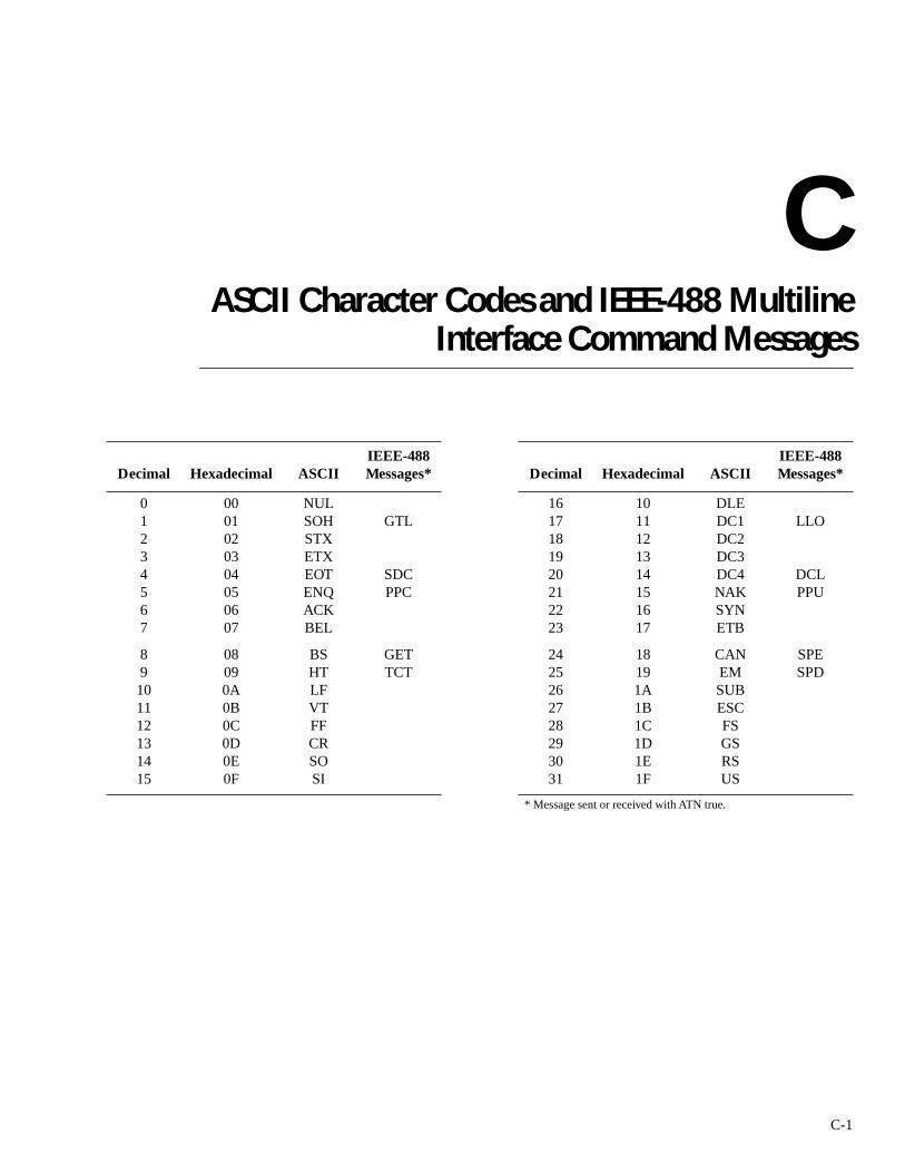
C
ASCII Character Codes and IEEE-488 MultilineInterface Command Messages
C-1
Decimal Hexadecimal ASCIIIEEE-488 Messages* Decimal Hexadecimal ASCII
IEEE-488 Messages*
01234567
0001020304050607
NULSOHSTXETXEOTENQACKBEL
GTL
SDCPPC
1617181920212223
1011121314151617
DLEDC1DC2DC3DC4NAKSYNETB
LLO
DCLPPU
89101112131415
08090A0B0C0D0E0F
BSHTLFVTFFCRSOSI
GETTCT
2425262728293031
18191A1B1C1D1E1F
CANEMSUBESCFSGSRSUS
SPESPD
* Message sent or received with ATN true.

ASCII Character Codes and IEEE-488 MultilineInterface Command Messages
C-2
Decimal Hexadecimal ASCIIIEEE-488 Messages* Decimal Hexadecimal ASCII
IEEE-488 Messages*
32333435363738
20212223242526
SP!”#$%&
MLA 0MLA 1MLA 2MLA 3MLA 4MLA 5MLA 6
64656667686970
40414243444546
@ABCDEF
MTA 0MTA 1MTA 2MTA 3MTA 4MTA 5MTA 6
394041424344454647
2728292A2B2C2D2E2F
’()*+’-./
MLA 7MLA 8MLA 9MLA 10MLA 11MLA 12MLA 13MLA 14MLA 15
717273747576777879
4748494A4B4C4D4E4F
GHIJKLMNO
MTA 7MTA 8MTA 9MTA 10MTA 11MTA 12MTA 13MTA 14MTA 15
4849505152535455
3031323334353637
01234567
MLA 16MLA 17MLA 18MLA 19MLA 20MLA 21MLA 22MLA 23
8081828384858687
5051525354555657
PQRSTUVW
MTA 16MTA 17MTA 18MTA 19MTA 20MTA 21MTA 22MTA 23
5657585960616263
38393A3B3C3D3E3F
89:;<=>?
MLA 24MLA 25MLA 26MLA 27MLA 28MLA 29MLA 30
UNL
8889909192939495
58595A5B5C5D5E5F
XYZ[\]«æ
MTA 24MTA 25MTA 26MTA 27MTA 28MTA 29MTA 30
UNL
* Message sent or received with ATN true. Numbers shown repre-sent primary address resulting in MLA (My Listen Address).
* Message sent or received with ATN true. Numbers shown are pri-mary address resulting in MTA (My Talk Address).

ASCII Character Codes and IEEE-488 MultilineInterface Command Messages
C-3
Decimal Hexadecimal ASCIIIEEE-488 Messages* Decimal Hexadecimal ASCII
IEEE-488 Messages*
96979899100101102103
6061626364656667
«abcdefg
MSA 0, PPEMSA 1, PPEMSA 2, PPEMSA 3, PPEMSA 4, PPEMSA 5, PPEMSA6, PPEMSA 7, PPE
112113114115116117118119
7071727374757677
pqrstuvw
MSA 16, PPDMSA 17, PPDMSA 18, PPDMSA 19, PPDMSA 20, PPDMSA 21, PPDMSA 22, PPDMSA 23, PPD
104105106107108109110111
68696A6B6C6D6E6F
hijklmno
MSA 8, PPEMSA 9, PPEMSA 10, PPEMSA 11, PPEMSA 12, PPEMSA 13, PPEMSA 14, PPEMSA 15, PPE
120121122123124125126127
78797A7B7C7D7E7F
xyz|~
DEL
MSA 24, PPDMSA 25, PPDMSA 26, PPDMSA 27, PPDMSA 28, PPDMSA 29, PPDMSA 30, PPD
* Message sent or received with ATN true. Numbers represent second-ary address resulting in MSA (My Secondary Address).

D
IEEE-488 Bus Overview
D-1
Introduction
Basically, the IEEE-488 bus is simply a communication sys-tem between two or more electronic devices. A device can beeither an instrument or a computer. When a computer is usedon the bus, it serves to supervise the communicationexchange between all the devices and is known as the con-troller. Supervision by the controller consists of determiningwhich device will talk and which device will listen. As atalker, a device will output information and as a listener, adevice will receive information. To simplify the task of keep-ing track of the devices, a unique address number is assignedto each one.
On the bus, only one device can talk at a time and isaddressed to talk by the controller. The device that is talkingis known as the active talker. The devices that need to listento the talker are addressed to listen by the controller. Eachlistener is then referred to as an active listener. Devices thatdo not need to listen are instructed to unlisten. The reason forthe unlisten instruction is to optimize the speed of bus infor-mation transfer since the task of listening takes up bus time.
Through the use of control lines, a handshake sequence takesplace in the transfer process of information from a talker to alistener. This handshake sequence helps ensure thecredibility of the information transfer. The basic handshakesequence between an active controller (talker) and a listeneris as follows:
1. The listener indicates that it is ready to listen.
2. The talker places the byte of data on the bus and indi-cates that the data is available to the listener.
3. The listener, aware that the data is available, accepts thedata and then indicates that the data has been accepted.
4. The talker, aware that the data has been accepted, stopssending data and indicates that data is not being sent.
5. The listener, aware that there is no data on the bus, indi-cates that it is ready for the next byte of data.
Bus description
The IEEE-488 bus, which is also frequently referred to as theGPIB (General Purpose Interface Bus), was designed as aparallel transfer medium to optimize data transfer withoutusing an excessive number of bus lines. In keeping with thisgoal, the bus has only eight data lines that are used for bothdata and with most commands. Five bus management linesand three handshake lines round out the complement of bussignal lines.
A typical set up for controlled operation is shown in FigureD-1. Generally, a system will contain one controller and anumber of other instruments to which the commands aregiven. Device operation is categorized into three operators:controller, talker and listener. The controller does what itsname implies; it controls the instruments on the bus. Thetalker sends data while a listener receives data. Depending onthe type of instrument, any particular device can be a talkeronly, a listener only or both a talker and listener.
There are two categories of controllers: system controller,and basic controller. Both are able to control other instru-ments, but only the system controller has the absoluteauthority in the system. In a system with more than one con-troller, only one controller may be active at any given time.Certain protocol is used to pass control from one controllerto another.

IEEE-488 Bus Overview
D-2
.
The IEEE-488 bus is limited to 15 devices, including thecontroller. Thus, any number of talkers and listeners up tothat limit may be present on the bus at one time. Althoughseveral devices may be commanded to listen simultaneously,the bus can have only one active talker, or communicationswould be scrambled.
A device is placed in the talk or listen state by sending anappropriate talk or listen command. These talk and listencommands are derived from an instrument’s primaryaddress. The primary address may have any value between 0and 31, and is generally set by rear panel DIP switches orprogrammed in from the front panel of the instrument. Theactual listen address value sent out over the bus is obtainedby ORing the primary address with $20. For example, if the
Figure D-1IEEE-488 bus configuration
DEVICE 1 ABLE TO TALK, LISTENAND CONTROL (COMPUTER)
DEVICE 3ONLY ABLE TO LISTEN (PRINTER)
DEVICE 4ONLY ABLE TO TALK
DAVNRFDNDAC
IFCATNSRQRENEOI
D IO1 ... 8 DATA (8 LINES)
HANDSHAKE
BUSMANAGEMENT
DATA BUS
DATA BYTETRANSFER CONTROL
GENERAL INTERFACEMANAGEMENT
DEVICE 2 ABLE TO TALK AND LISTEN 7001
TO OTHER DEVICES
primary address is $16, the actual listen address is $36 ($36= $16 + $20). In a similar manner, the talk address isobtained by ORing the primary address with $40. With thepresent example, the talk address derived from a primaryaddress of 16 decimal would be $56 ($56 = $16 + $40).
The IEEE-488 standards also include another addressingmode called secondary addressing. Secondary addresses liein the range of $60-$7F. Note, however, that many devices,including the Model 2002, do not use secondary addressing.
Once a device is addressed to talk or listen, the appropriatebus transactions take place. For example: if the instrument isaddressed to talk, it places its data string on the bus one byteat a time. The controller reads the information and the appro-priate software can be used to direct the information to thedesired location.
Bus lines
The signal lines on the IEEE-488 bus are grouped into threedifferent categories: data lines, management lines and hand-shake lines. The data lines handle bus data and commands,while the management and handshake lines ensure thatproper data transfer and operation takes place. Each bus lineis active low, with approximately zero volts representing alogic 1 (true). The following paragraphs describe the opera-tion of these lines.
Data lines
The IEEE-488 bus uses eight data lines that transfer data onebyte at a time. DIO1 (Data Input/Output) through DIO8(Data Input/Output) are the eight data lines used to transmitboth data and multiline commands and are bidirectional. Thedata lines operate with low true logic.
Bus management lines
The five bus management lines help to ensure proper inter-face control and management. These lines are used to sendthe uniline commands.
ATN (Attention) — The ATN line is one of the more impor-tant management lines in that the state of this line determineshow information on the data bus is to be interpreted.
IFC (Interface Clear) — As the name implies, the IFC linecontrols clearing of instruments from the bus.
REN (Remote Enable) —The REN line is used to place theinstrument on the bus in the remote mode.

IEEE-488 Bus Overview
D-3
EOI (End or Identify) — The EOI is usually used to mark theend of a multi-byte data transfer sequence.
SRQ (Service Request) — This line is used by devices whenthey require service from the controller.
Handshake lines
The bus handshake lines operate in an interlocked sequence.This method ensures reliable data transmission regardless ofthe transfer rate. Generally, data transfer will occur at a ratedetermined by the slowest active device on the bus.
One of the three handshake lines is controlled by the source(the talker sending information), while the remaining twolines are controlled by accepting devices (the listener or lis-teners receiving the information). The three handshake linesare:
DAV (DATA VALID) — The source controls the state of theDAV line to indicate to any listening devices whether or notdata bus information is valid.
NRFD (Not Ready For Data) — The acceptor controls thestate of NRFD. It is used to signal to the transmitting deviceto hold off the byte transfer sequence until the acceptingdevice is ready.
NDAC (Not Data Accepted) — NDAC is also controlled bythe accepting device. The state of NDAC tells the sourcewhether or not the device has accepted the data byte.
The complete handshake sequence for one data byte isshown in Figure D-2. Once data is placed on the data lines,the source checks to see that NRFD is high, indicating thatall active devices are ready. At the same time, NDAC shouldbe low from the previous byte transfer. If these conditions arenot met, the source must wait until NDAC and NRFD havethe correct status. If the source is a controller, NRFD andNDAC must be stable for at least 100nsec after ATN is settrue. Because of the possibility of a bus hang up, many con-trollers have time-out routines that display messages in casethe transfer sequence stops for any reason.
Once all NDAC and NRFD are properly set, the source setsDAV low, indicating to accepting devices that the byte on thedata lines is now valid. NRFD will then go low, and NDACwill go high once all devices have accepted the data. Each
device will release NDAC at its own rate, but NDAC will notbe released to go high until all devices have accepted the databyte.
The sequence just described is used to transfer both data, talkand listen addresses, as well as multiline commands. Thestate of the ATN line determines whether the data bus con-tains data, addresses or commands as described in the fol-lowing paragraph.
Bus commands
The instrument may be given a number of special bus com-mands through the IEEE-488 interface. This section brieflydescribes the purpose of the bus commands which aregrouped into the following three categories.
1. Uniline Commands — Sent by setting the associated buslines true. For example, to assert REN (Remote Enable),the REN line would be set low (true).
2. Multiline Commands — General bus commands whichare sent over the data lines with the ATN line true (low).
3. Common Commands — Commands that are common toall devices on the bus; sent with ATN high (false).
4. SCPI Commands — Commands that are particular toeach device on the bus; sent with ATN (false).
These bus commands and their general purpose are summa-rized in Table D-1.
Figure D-2IEEE-488 handshake sequence
DATA
DAV
SOURCE
SOURCE
VALID
NRFD
NDAC
ACCEPTOR
ACCEPTOR
ALL READY
ALL ACCEPTED

IEEE-488 Bus Overview
D-4
Uniline commands
ATN, IFC and REN are asserted only by the controller. SRQis asserted by an external device. EOI may be asserted eitherby the controller or other devices depending on the directionof data transfer. The following is a description of each com-mand. Each command is sent by setting the correspondingbus line true.
REN (Remote Enable) — REN is sent to set up instrumentson the bus for remote operation. When REN is true, deviceswill be removed from the local mode. Depending on deviceconfiguration, all front panel controls except the LOCALbutton (if the device is so equipped) may be locked out whenREN is true. Generally, REN should be sent before attempt-ing to program instruments over the bus.
EOI (End or Identify) — EOI is used to positively identifythe last byte in a multi-byte transfer sequence, thus allowingdata words of various lengths to be transmitted easily.
IFC (Interface Clear) — IFC is used to clear the interface andreturn all devices to the talker and listener idle states.
Table D-1IEEE-488 bus command summary
Command type CommandState of ATN line Comments
Uniline REN (Remote Enable)EOIIFC (Interface Clear)ATN (Attention)SRQ
XXXLowX
Set up devices for remote operation.Marks end of transmission.Clears interface.Defines data bus contents.Controlled by external device.
MultilineUniversal LLO (Local Lockout)
DCL (Device Clear)SPE (Serial Enable)SPD (Serial Poll Disable)
LowLowLowLow
Locks our local operation.Returns device to default conditions.Enables serial polling.Disables serial polling.
Addressed SDC (Selective Device Clear)GTL (Go To Local)
LowLow
Returns unit to default conditions.Returns device to local.
Unaddressed UNL (Unlisten)UNT (Untalk)
LowLow
Removes all listeners from the bus.Removes any talkers from the bus.
Common — High Programs IEEE-488.2 compatible instruments for common operations.
SCPI — High Programs SCPI compatible instruments for particular operations.
ATN (Attention) — The controller sends ATN while trans-mitting addresses or multiline commands.
SRQ (Service Request) — SRQ is asserted by a device whenit requires service from a controller.
Universal multiline commands
Universal commands are those multiline commands thatrequire no addressing. All devices equipped to implementsuch commands will do so simultaneously when the com-mands are transmitted. As with all multiline commands,these commands are transmitted with ATN true.
LLO (Local Lockout) — LLO is sent to the instrument tolock out the LOCAL key and thus all their front panelcontrols.
DCL (Device Clear) — DCL is used to return instruments tosome default state. Usually, instruments return to theirpower-up conditions.
IEEE-488 Bus Overview
D-5
SPE (Serial Poll Enable) — SPE is the first step in the serialpolling sequence which is used to determine which devicehas requested service.
SPD (Serial Poll Disable) — SPD is used by the controller toremove all devices on the bus from the serial poll mode andis generally the last command in the serial polling sequence.
Addressed multiline commands
Addressed commands are multiline commands that must bepreceded by the device listen address before that instrumentwill respond to the command in question. Note that only theaddressed device will respond to these commands. Both thecommands and the address preceding it are sent with ATNtrue.
SDC (Selective Device Clear) — The SDC command per-forms essentially the same function as the DCL commandexcept that only the addressed device responds. Generally,instruments return to their power-up default conditions whenresponding to the SDC command.
GTL (Go To Local) — The GTL command is used to removeinstruments from the remote mode. With some instruments,GTL also unlocks front panel controls if they were previ-ously locked out with the LLO command.
GET (Group Execute Trigger) — The GET command is usedto trigger devices to perform a specific action that dependson device configuration (for example, take a reading).Although GET is an addressed command, many devicesrespond to GET without addressing.
Address commands
Addressed commands include two primary command groupsand a secondary address group. ATN is true when these com-mands are asserted. The commands include:
LAG (Listen Address Group) — These listen commands arederived from an instrument’s primary address and are used toaddress devices to listen. The actual command byte isobtained by ORing the primary address with $20.
TAG (Talk Address Group) — The talk commands arederived from the primary address by ORing the address with$40. Talk commands are used to address devices to talk.
SCG (Secondary Command Group) — Commands in thisgroup provide additional addressing capabilities. Manydevices (including the Model 2002) do not use thesecommands.
Unaddress commands
The two unaddress commands are used by the controller toremove any talkers or listeners from the bus. ATN is truewhen these commands are asserted.
UNL (Unlisten) — Listeners are placed in the listener idlestate by the UNL command.
UNT (Untalk) — Any previously commanded talkers will beplaced in the talker idle state by the UNT command.
Common commands
Common commands are commands that are common to alldevices on the bus. These commands are designated anddefined by the IEEE-488.2 standard.
Generally, these commands are sent as one or more ASCIIcharacters that tell the device to perform a commonoperation, such as reset. The IEEE-488 bus treats thesecommands as data in that ATN is false when the commandsare transmitted.
SCPI commands
SCPI commands are commands that are particular to eachdevice on the bus. These commands are designated by theinstrument manufacturer, and are based on the instrumentmodel defined by the Standard Commands for Programma-ble Instruments (SCPI) Consortium’s SCPI standard.
Generally, these commands are sent as one or more ASCIIcharacters that tell the device to perform a particular opera-tion, such as setting a range or closing a relay. The IEEE-488bus treats these commands as data in that ATN is false whenthe commands are transmitted.
Command codes
Command codes for the various commands that use the datalines are summarized in Figure D-3. Hexadecimal and thedecimal values for the various commands are listed in TableD-2.
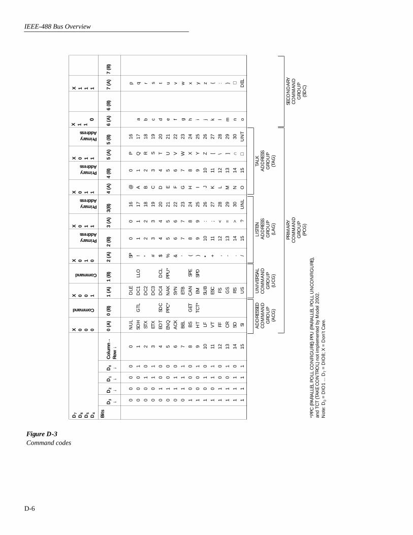
IEEE-488 Bus Overview
D-6
Figure D-3Command codes
D7
D6
D5
D4
X 0 0 0
Command
X 0 0 1
Command
X 0 1 0
PrimaryAddress
X 0 1 1
PrimaryAddress
X 0 1 1
PrimaryAddress
X 0 1 1
PrimaryAddress
X 1 10
X 1 1 1
Bit
sD
3
↓D
2
↓D
1
↓D
0
↓C
olum
n→R
ow ↓
0 (A
)0
(B)
1 (A
)1
(B)
2 (A
)2
(B)
3 (A
)3(
B)
4 (A
)4
(B)
5 (A
)5
(B)
6 (A
)6
(B)
7 (A
)7
(B)
0 0 0 0 0 0 0 0 1 1 1 1 1 1 1 1
0 0 0 0 1 1 1 1 0 0 0 0 1 1 1 1
0 0 1 1 0 0 1 1 0 0 1 1 0 0 1 1
0 1 0 1 0 0 0 1 0 1 0 1 0 1 0 1
0 1 2 3 4 5 6 7 8 9 10 11 12 13 14 15
NU
L
SOH
STX
ETX
EOT
ENQ
AC
K
BEL BS
HT
LF VT FF CR
SO SI
GTL
SDC
PPC
*
GET
TCT*
DLE
DC
1
DC
2
DC
3
DC
4
NA
K
SYN
ETB
CA
N
EM SUB
ESC
FS GS
RS
US
LLO
DC
L
PPU
*
SPE
SPD
SP ! “ # $ % & ‘ ( ) • + , - . /
0 1 2 3 4 5 6 7 8 9 10 11 12 13 14 15
0 1 2 3 4 5 6 7 8 9 : ; < = > ?
16 17 18 19 20 21 22 23 24 25 26 27 28 29 30 UN
L
@ A B C D E F G H I J K L M N O
0 1 2 3 4 5 6 7 8 9 10 11 12 13 14 15
P Q R S T U V W X Y Z [ \ ] ∩
16 17 18 19 20 21 22 23 24 25 26 27 28 29 30 UN
T
a b c d e f g h i j k l m n o
p q r s t u v w x y z : ≅D
EL
AD
DR
ESSE
DC
OM
MA
ND
GR
OU
P(A
CG
)
UN
IVER
SAL
CO
MM
AN
DG
RO
UP
(UC
G)
LIST
ENA
DD
RES
SG
RO
UP
(LA
G)
TALK
AD
DR
ESS
GR
OU
P(T
AG
)
PRIM
ARY
CO
MM
AN
DG
RO
UP
(PC
G)
SEC
ON
DA
RYC
OM
MA
ND
GR
OU
P(S
DC
)
*PPC
(PA
RA
LLEL
PO
LL C
ON
FIG
UR
E) P
PU (P
AR
ALL
EL P
OLL
UN
CO
NFI
GU
RE)
,an
d TC
T (T
AK
E C
ON
TRO
L) n
ot im
plem
ente
d by
Mod
el 2
002.
Not
e: D
0 =
DIO
1 ...
D7
= D
IO8;
X =
Don
’t C
are.

IEEE-488 Bus Overview
D-7
Table D-2
Hexadecimal and decimal command codes
Command Hex valueDecimal value
GTLSDCGETLLODCLSPESPDLAGTAGSCGUNLUNT
0104081114181920-3F40-5F60-7F3F5F
1481720242532-6364-9596-1276395
Table D-3Typical addressed command sequence
Step Command ATN state
Data bus
ASCII Hex Decimal
1234
UNLLAG*SDC
Set lowStays lowStays lowReturns high
?0
EOT
3F3004
63484
*Assumes primary address = 16.
Table D-4Typical common command sequence
Step Command ATN state
Data bus
ASCII Hex Decimal
123456
UNLLAG*DataDataDataData
Set lowStays lowSet highStays highStays highStays high
?0*RST
3F302A525354
634842828384
*Assumes primary address = 16.
Typical command sequences
For the various multiline commands, a specific bus sequencemust take place to properly send the command. In particular,the correct listen address must be sent to the instrumentbefore it will respond to addressed commands. Table D-3lists a typical bus sequence for sending the addressed multi-line commands. In this instance, the SDC command is beingsent to the instrument. UNL is generally sent as part of thesequence to ensure that no other active listeners are present.Note that ATN is true for both the listen command and theSDC command byte itself.
Table D-4 gives a typical common command sequence. Inthis instance, ATN is true while the instrument is beingaddressed, but it is set high while sending the common com-mand string.
IEEE command groups
Command groups supported by the Model 2002 are listed inTable D-5. Common commands and SCPI commands are notincluded in this list.
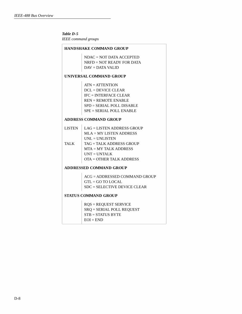
IEEE-488 Bus Overview
D-8
Table D-5
IEEE command groups
HANDSHAKE COMMAND GROUP
NDAC = NOT DATA ACCEPTEDNRFD = NOT READY FOR DATADAV = DATA VALID
UNIVERSAL COMMAND GROUP
ATN = ATTENTIONDCL = DEVICE CLEARIFC = INTERFACE CLEARREN = REMOTE ENABLESPD = SERIAL POLL DISABLESPE = SERIAL POLL ENABLE
ADDRESS COMMAND GROUP
LISTEN
TALK
LAG = LISTEN ADDRESS GROUPMLA = MY LISTEN ADDRESSUNL = UNLISTENTAG = TALK ADDRESS GROUPMTA = MY TALK ADDRESSUNT = UNTALKOTA = OTHER TALK ADDRESS
ADDRESSED COMMAND GROUP
ACG = ADDRESSED COMMAND GROUPGTL = GO TO LOCALSDC = SELECTIVE DEVICE CLEAR
STATUS COMMAND GROUP
RQS = REQUEST SERVICESRQ = SERIAL POLL REQUESTSTB = STATUS BYTEEOI = END
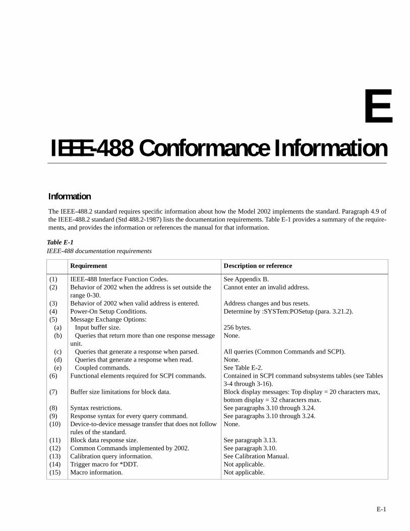
E
IEEE-488 Conformance Information
E-1
Information
The IEEE-488.2 standard requires specific information about how the Model 2002 implements the standard. Paragraph 4.9 ofthe IEEE-488.2 standard (Std 488.2-1987) lists the documentation requirements. Table E-1 provides a summary of the require-ments, and provides the information or references the manual for that information.
Table E-1
IEEE-488 documentation requirements
Requirement Description or reference
(1)(2)
(3)(4)(5)
(a)(b)
(c)(d)(e)
(6)
(7)
(8)(9)(10)
(11)(12)(13)(14)(15)
IEEE-488 Interface Function Codes.Behavior of 2002 when the address is set outside the range 0-30.Behavior of 2002 when valid address is entered.Power-On Setup Conditions. Message Exchange Options:
Input buffer size.Queries that return more than one response message
unit.Queries that generate a response when parsed.Queries that generate a response when read.Coupled commands.
Functional elements required for SCPI commands.
Buffer size limitations for block data.
Syntax restrictions.Response syntax for every query command.Device-to-device message transfer that does not follow rules of the standard.Block data response size. Common Commands implemented by 2002.Calibration query information.Trigger macro for *DDT.Macro information.
See Appendix B.Cannot enter an invalid address.
Address changes and bus resets.Determine by :SYSTem:POSetup (para. 3.21.2).
256 bytes.None.
All queries (Common Commands and SCPI).None. See Table E-2.Contained in SCPI command subsystems tables (see Tables 3-4 through 3-16).Block display messages: Top display = 20 characters max, bottom display = 32 characters max.See paragraphs 3.10 through 3.24.See paragraphs 3.10 through 3.24.None.
See paragraph 3.13.See paragraph 3.10.See Calibration Manual.Not applicable.Not applicable.

IEEE-488 Conformance Information
E-2
(16)(17)(18)(19)
(20)(21)(22)
(23)
Response to *IDN (identification).Storage area for *PUD and *PUD? Resource description for *RDT and *RDT?Effects of *RST, *RCL and *SAV.
*TST information.Status register structure.Sequential or overlapped commands.
Operation complete messages.
See paragraph 3.10.4.Not applicable.Not applicable.See paragraphs 3.10.9, 3.10.8, 3.10.10, and Tables 3-4 through 3-16.See paragraph 3.10.14.See paragraph 3.7.All are sequential except :INIT and :INIT:CONT ON, which are overlapped.*OPC; see paragraph 3.10.5,*OPC?; see paragraph 3.10.6,*WAI; see paragraph 3.10.15.
Table E-1 (cont.)
IEEE-488 documentation requirements
Requirement Description or reference
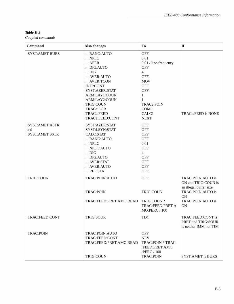
IEEE-488 Conformance Information
E-3
Table E-2
Coupled commands
Command Also changes To If
:SYST:AMET BURS ... :RANG:AUTO ... :NPLC ... :APER ... :DIG:AUTO ... :DIG ... :AVER:AUTO ... :AVER:TCON :INIT:CONT :SYST:AZER:STAT:ARM:LAY1:COUN:ARM:LAY2:COUN:TRIG:COUN :TRACe:EGR :TRACe:FEED :TRACe:FEED:CONT
OFF0.010.01 / line-frequencyOFF4OFFMOVOFFOFF11TRACe:POINCOMPCALC1NEXT
TRACe:FEED is NONE
:SYST:AMET:ASTRand:SYST:AMET:SSTR
:SYST:AZER:STAT:SYST:LSYN:STAT:CALC:STAT... :RANG:AUTO... :NPLC... :NPLC:AUTO... :DIG... :DIG:AUTO... :AVER:STAT... :AVER:AUTO... :REF:STAT
OFFOFFOFFOFF0.01OFF4OFFOFFOFFOFF
:TRIG:COUN :TRAC:POIN:AUTO
:TRAC:POIN
:TRAC:FEED:PRET:AMO:READ
OFF
TRIG:COUN
TRIG:COUN * TRAC:FEED:PRET:AMO:PERC / 100
TRAC:POIN:AUTO is ON and TRIG:COUN is an illegal buffer sizeTRAC:POIN:AUTO is ONTRAC:POIN:AUTO is ON
:TRAC:FEED:CONT :TRIG:SOUR TIM TRAC:FEED:CONT is PRET and TRIG:SOUR is neither IMM nor TIM
:TRAC:POIN :TRAC:POIN:AUTO :TRAC:FEED:CONT :TRAC:FEED:PRET:AMO:READ
:TRIG:COUN
OFFNEVTRAC:POIN * TRAC :FEED:PRET:AMO :PERC / 100TRAC:POIN SYST:AMET is BURS
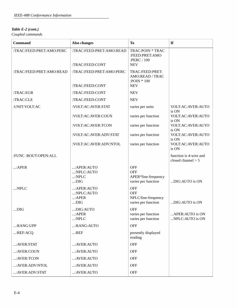
IEEE-488 Conformance Information
E-4
:TRAC:FEED:PRET:AMO:PERC :TRAC:FEED:PRET:AMO:READ
:TRAC:FEED:CONT
TRAC:POIN * TRAC :FEED:PRET:AMO :PERC / 100NEV
:TRAC:FEED:PRET:AMO:READ :TRAC:FEED:PRET:AMO:PERC
:TRAC:FEED:CONT
TRAC:FEED:PRET: AMO:READ / TRAC :POIN * 100NEV
:TRAC:EGR :TRAC:FEED:CONT NEV
:TRAC:CLE :TRAC:FEED:CONT NEV
:UNIT:VOLT:AC :VOLT:AC:AVER:STAT
:VOLT:AC:AVER:COUN
:VOLT:AC:AVER:TCON
:VOLT:AC:AVER:ADV:STAT
:VOLT:AC:AVER:ADV:NTOL
varies per units
varies per function
varies per function
varies per function
varies per function
VOLT:AC:AVER:AUTO is ONVOLT:AC:AVER:AUTO is ONVOLT:AC:AVER:AUTO is ONVOLT:AC:AVER:AUTO is ONVOLT:AC:AVER:AUTO is ON
:FUNC :ROUT:OPEN:ALL function is 4-wire and closed channel > 5
...:APER ...:APER:AUTO ...:NPLC:AUTO ...:NPLC ...:DIG
OFFOFFAPER*line-frequencyvaries per function ...DIG:AUTO is ON
...:NPLC ...:APER:AUTO ...:NPLC:AUTO ...:APER ...:DIG
OFFOFFNPLC/line-frequencyvaries per function ...DIG:AUTO is ON
...:DIG ...:DIG:AUTO ...:APER ...:NPLC
OFFvaries per functionvaries per function
...APER:AUTO is ON
...NPLC:AUTO is ON
...:RANG:UPP ...:RANG:AUTO OFF
...:REF:ACQ ...:REF presently displayed reading
...:AVER:STAT ...:AVER:AUTO OFF
...:AVER:COUN ...:AVER:AUTO OFF
...:AVER:TCON ...:AVER:AUTO OFF
...:AVER:ADV:NTOL ...:AVER:AUTO OFF
...:AVER:ADV:STAT ...:AVER:AUTO OFF
Table E-2 (cont.)
Coupled commands
Command Also changes To If

IEEE-488 Conformance Information
E-5
...:DET:FUNC ...:APER ...:DIG ...:AVER:STAT ...:AVER:COUN n ...:AVER:TCON n ...:AVER:ADV:STAT n ...:AVER:ADV:NTOL n
varies per functionvaries per functionvaries per functionvaries per functiovaries per functiovaries per functiovaries per functio
...APER:AUTO is ON
...DIG:AUTO is ON
...AVER:AUTO is ON
...AVER:AUTO is ON
...AVER:AUTO is ON
...AVER:AUTO is ON
...AVER:AUTO is ON
:RES:OCOM :RES:RANG:UPP
:RES:RANG:AUTO:ULIM
:RES:RANG:AUTO:LLIM
200k
200k
200k
RES:OCOM is ON and RES:RANG:UPP > 200kRES:OCOM is ON and RES:RANG:AUTO:ULIM > 200kRES:OCOM is ON and RES:RANG:AUTO:LLIM > 200k
:CURR:DC:METH :CURR:DC:RANG:UPP :CURR:DC:RANG:AUTO:CURR:DC:AVER:STAT
:CURR:DC:AVER:COUN
:CURR:DC:AVER:TCON
:CURR:DC:AVER:ADV:STAT
:CURR:DC:AVER:ADV:NTOL
12OFFvaries per function
varies per function
varies per function
varies per function
varies per function
CURR:DC:METH is ICIRCURR:DC:METH is ICIRCURR:DC:AVER:AUTO is ONCURR:DC:AVER:AUTO is ONCURR:DC:AVER:AUTO is ONCURR:DC:AVER:AUTO is ONCURR:DC:AVER:AUTO is ON
:FREQ:THR:VOLT:TTL :FREQ:THR:VOLT:RANG:FREQ:THR:VOLT:LEV
100.8
:TEMP:TRAN :ROUT:SCAN:INT
:ROUT:SCAN:INT:FUNC
:TEMP:DIG
very complicated algo-rithmvery complicated algo-rithmvaries per transducer TEMP:DIG:AUTO is ON
:TEMP:RTD:TYPE :TEMP:RTD:ALPH
:TEMP:RTD:BETA
:TEMP:RTD:DELT
:TEMP:RTD:RZER
varies per RTD type
varies per RTD type
varies per RTD type
varies per RTD type
TEMP:RTD:TYPE is not USERTEMP:RTD:TYPE is not USERTEMP:RTD:TYPE is not USERTEMP:RTD:TYPE is not USER
:TEMP:RTD:ALPH :TEMP:RTD:TYPE USER
Table E-2 (cont.)
Coupled commands
Command Also changes To If

IEEE-488 Conformance Information
E-6
:TEMP:RTD:BETA :TEMP:RTD:TYPE USER
:TEMP:RTD:DELT :TEMP:RTD:TYPE USER
:TEMP:RTD:RZER :TEMP:RTD:TYPE USER
:TEMP:TC:TYPE :TEMP:DIG varies per TC type TEMP:DIG:AUTO is ON
:ROUT:CLOS :ROUT:SCAN:LSEL NONE
:ROUT:OPEN :ROUT:SCAN:LSEL NONE the command actually opens a channel
:ROUT:OPEN:ALL :ROUT:SCAN:LSEL NONE
:ROUT:SCAN:INT :ROUT:SCAN:LSEL INT
:ROUT:SCAN:RAT:FUNC ...:AVER:STAT ...:AVER:COUN ...:AVER:TCON ...:AVER:ADV:STAT ...:AVER:ADV:NTOL n
varies per functionvaries per functionvaries per functionvaries per functionvaries per functio
...AVER:AUTO is ON
...AVER:AUTO is ON
...AVER:AUTO is ON
...AVER:AUTO is ON
...AVER:AUTO is ON
:ROUT:SCAN:LSEL ...:AVER:STAT varies per function ...:AVER:COUN...:AVER:TCON ...:AVER:ADV:STAT ...:AVER:ADV:NTOL:FUNC
:FUNC
:ROUT:CLOS
:ROUT:CLOS
varies per functionvaries per functionvaries per functionvaries per functionvaries per function :ROUT:SCAN:RAT:FUNC:ROUT:SCAN:DELT :FUNC:ROUT:SCAN:RAT :MCH:ROUT:SCAN:DELT :MCH
...AVER:AUTO is ON
...AVER:AUTO is ON
...AVER:AUTO is ON
...AVER:AUTO is ON
...AVER:AUTO is ONROUT:SCAN:LSEL is RATROUT:SCAN:LSEL is DELTROUT:SCAN:LSEL is RATROUT:SCAN:LSEL is DELT
... = Valid function command words (i.e. :VOLT:DC, :VOLT:AC, etc.)
Table E-2 (cont.)
Coupled commands
Command Also changes To If

F
SCPI Conformance Information
F-1
Introduction
The Model 2002 complies with SCPI version 1991.0. Tables3-4 through 3-16 list the SCPI confirmed commands, and thenon-SCPI commands implemented by the Model 2002.

G
Example Programs
G-1
The following programs demonstrate various aspects ofModel 2002 operation. Most programs use only the Model2002 while some include additional equipment, such as theModel 2001-SCAN Scanner Card or a Model 7001 (or 7002)Switch System.
The programs are written in Microsoft QuickBASIC 4.5 orMicrosoft QuickC 2.0. Most examples use the Keithley(CEC) IEEE-488 interface cards. Other interfaces usedinclude IOtech and National GPIB.

Example Programs
G-2
Measure and Display Reading;:MEASure? Command
Microsoft QuickBASIC 4.5Keithley KPC-488.2 Interface
©1992, Keithley Instruments, Inc.
Description
Every time this program is run, the Model 2002 goes to themost sensitive DCV range and makes a single measurementusing the :MEASure command. The reading is then dis-played on the computer CRT.
Required equipment
• Model 2002 Multimeter
• Microsoft QuickBASIC 4.5
• Any one of the following IEEE-488 interfaces:
Keithley Model KPC-488.2
Keithley Model KPC-488.2AT
Capital Equipment Corporation PC<>488
The program assumes that the Model 2002 is set to address16.
Loading user library
The user library for QuickBASIC 4.5 is provided with theIEEE-488 interface (ieeeqb.qlb). Assuming QuickBASICand the user library are in the same DOS directory, enter thefollowing command line from the DOS prompt:
QB /L ieeeqb.qlb
The above command line will load QuickBASIC and theuser library.
Program (2002tst.bas)
CALL initialize(21, 0) ' Init as system controller
'MODEL 2002 COMMANDS
CALL send(16, "*CLS", Gpib.status%)CALL send(16, ":meas:volt:dc?", Gpib.status%) ' Measure DCVdata$ = SPACE$(80)CALL enter(data$, Gpib.len%, 16, Gpib.status%)PRINT data$ ' Display reading
END

Example Programs
G-3
• Any one of the following IEEE-488 interfaces:
Keithley Model KPC-488.2
Keithley Model KPC-488.2AT
Capital Equipment Corporation PC<>488
The program assumes that the Model 2002 is set to address16.
Loading user library
The user library for QuickBASIC 4.5 is provided with theIEEE-488 interface (ieeeqb.qlb). Assuming QuickBASICand the user library are in the same DOS directory, enter thefollowing command line from the DOS prompt:
QB /L ieeeqb.qlb
The above command line will load QuickBASIC and theuser library.
Program (2002rdg.bas)
k2002data$ = SPACE$(35)CALL Initialize(21, 0) ' Init as system controller
'--- Setup 2002 measurement modeCLSCALL SETOUTPUTEOS(10, 0)CALL SETINPUTEOS(10)CALL SEND(16, ":init:cont off", gpib.status%) ' Disable continuous
' initiationCALL SEND(16, ":sens:func 'volt:dc' ", gpib.status%) ' Select DCVCALL SEND(16, ":sens:volt:dc:dig 8", gpib.status%) ' Select 7 1/2 digit
' resolution
k2001data$ = SPACE$(255)CALL SEND(16, ":read?", gpib.status%) ' Perform measurementCALL Enter(k2001data$, Gpib.len%, 16, gpib.status%)k2001data$ = LEFT$(k2001data$, Gpib.len%) ' Display readingPRINT k2001data$
END
Measure and Display Reading;:READ? Command
Microsoft QuickBASIC 4.5Keithley KPC-488.2 Interface
©1992, Keithley Instruments, Inc.
Description
Every time this program is run, the Model 2002 goes to theDCV range and makes a single measurement using the:READ? command. The reading is then displayed on thecomputer CRT.
Required equipment
• Model 2002 Multimeter
• Microsoft QuickBASIC 4.5

Example Programs
G-4
then sent to the computer and displayed. This process contin-ues until a keystroke occurs.
Required equipment
• Model 2002 Multimeter
• Microsoft QuickC 2.0
• National GPIB PC Interface (interface software must beinstalled and configured as explained in the instructionmanual).
The program assumes that the Model 2002 is set to address16.
Program (confnat.c)
#include <stc.h>#include <stdio.h>#include <stdlib.h>#include <decl.h>#include <math.h>#include <graph.h>#include <string.h>#include <time.h>
#define k2002 16
main()
int stat, l;
char status, keych;char cmd[255];char ki2002[10];
_clearscreen(_GWINDOW);SendIFC(0); /* Set Controller to Addr 0 */
Send(0,k2002,":form:elem read",24L,NLend); /* Include only reading in data string */
while( !kbhit() )Send(0,k2002,":conf:freq",20L,NLend); /* Configure for one-shot FREQ measure-
ments */Send(0,k2002,":read?",6L,NLend); /* Make measurement */Receive(0,k2002,ki2002,20L,STOPend);printf("%s",ki2002); /* Display reading */
:CONFigure and :READ? Commands
Microsoft QuickC 2.0National GPIB PC Interface
©1992, Keithley Instruments, Inc.
Description
This program demonstrates the use of the :CONFigure and:READ? commands. In general, :CONFigure is used toselect the FREQ function and then performs a *RST. The:READ? command is used to make a measurement, which is

Example Programs
G-5
Keithley Model KPC-488.2
Keithley Model KPC-488.2AT
Capital Equipment Corporation PC<>488
The program assumes that the Model 2002 is set to address16.
Loading user library
The user library for QuickBASIC 4.5 is provided with theIEEE-488 interface (ieeeqb.qlb). Assuming QuickBASICand the user library are in the same DOS directory, enter thefollowing command line from the DOS prompt:
QB /L ieeeqb.qlb
The above command line will load QuickBASIC and theuser library.
Program (2002disp.bas)
CALL Initialize(21, 0) ' Init as system controller'--- Setup 2002 commands
CLS
' Enable message mode
CALL Send(16, ":disp:text:stat on", Gpib.status%)
' Display first message
CALL Send(16, ":disp:text:data 'GOOD MORNING!' ", Gpib.status%)SLEEP 2
' Display second message
CALL Send(16, ":disp:text:data 'HOW ARE YOU TODAY?' ", Gpib.status%)
END
Display User Defined Message
Microsoft QuickBASIC 4.5Keithley KPC-488.2 Interface
©1992, Keithley Instruments, Inc.
Description
This program simply displays a user defined message on thedisplay of the Model 2002.
Required equipment
• Model 2002 Multimeter
• Microsoft QuickBASIC 4.5
• Any one of the following IEEE-488 interfaces:

Example Programs
G-6
This program configures the Model 2002 as follows:
Function:
Ω
4
Filter: Repeat averaging mode, 5 readings
Resolution: 7 1/2 digits
Required equipment
• Model 2002 Multimeter
• Microsoft QuickBASIC 4.5
• IOtech GP488B IEEE-488 Interface
• IOtech Driver488 Software (installed and configured asdescribed in the instruction manual for the interface).
The program assumes that the Model 2002 is set to address16.
Program (ohmsbufi.bas)
OPEN "\dev\ieeeout" FOR OUTPUT AS #1 ' Open GP488B for outputIOCTL #1, "break" ' Reset Personal488PRINT #1, "reset"OPEN "\dev\ieeein" FOR INPUT AS #2 ' Open GP488B for inputCLSPRINT #1, "TIME OUT 5"PRINT #1, "TERM OUT LF EOI"PRINT #1, "TERM IN LF EOI"
'--- Set up 2002 for 5 readings, 7.5 digits, 4-wire ohms, 10 NPLC, store'readings in buffer, return buffered readings to host computer and then'repeat the process.
PRINT #1, "Output 16; *RST" ' Perform reset
PRINT #1, "Output 16; :sens:func 'fres';" ' Set for 4-wire ohms
cmd$ = ":sens:fres:nplc 10; dig 7.5; aver:coun 5; tcon rep;"cmd$ = cmd$ + "Stat On"
' Set for 10 PLC,' 7.5 digits, average' 5 readings, repeat mode
PRINT #1, "Output 16;"; cmd$
PRINT #1, "Output 16; :form:elem read" ' Return readings onlycmd$ = ":init:cont off; :abor; :trac:cle" ' Turn off trigger model,
' Clear data bufferPRINT #1, "Output 16;"; cmd$
cmd$ = ":arm:seq1:lay1:sour bus; coun 1; :arm:seq1:lay2:sour imm;"cmd$ = cmd$ + ":trig:seq1:sour imm; coun 5; :stat:meas:PTR 512; NTR 0"
' Set the 2002 to start' taking readings on a' bus trigger. Set Measure' Event Register to flag' on buffer full.
PRINT #1, "Output 16;"; cmd$
Four-Wire Ohms Measurements
Microsoft QuickBASIC 4.5IOtech Interface and Driver-488 Software
©1992, Keithley Instruments, Inc.
Description
This program configures the Model 2002 to make four-wireohms measurements. The Model 2002 makes five measure-ments, stores them in its internal buffer and then sends themto the computer where the readings are displayed. This pro-cess continues until a keystroke occurs to stop the program.

Example Programs
G-7
Program (ohmsbufi.bas) (cont.)
PRINT #1, "Output 16; *CLS" ' Clear 2002
cmd$ = ":trac:feed sens; poin 5; feed:cont next;"cmd$ = cmd$ + ":init:cont on" ' Set up buffer to store
' 5 points after averaging,' arm 2002.
PRINT #1, "Output 16;"; cmd$
PRINT #1, "Output 16; *TRG" ' Trigger 2002 to start
PRINT "Data collection in progress......."
DOPRINT #1, "Output 16; :stat:meas:even?" ' Check to see if the buffer
' is full.PRINT #1, "Enter 16" ' Get status valueLINE INPUT #2, pollval$LOOP UNTIL (VAL(pollval$) AND 512) = 512
resistance$ = SPACE$(100)PRINT #1, "Output 16; :trac:data?" ' Get dataPRINT #1, "Enter 16"LINE INPUT #2, resistance$
FOR x = 0 TO 4reading$ = MID$(resistance$, x * 15 + 1, 13)PRINT reading$NEXT x
cmd$ = ":init:cont off; :abor; :trace:cle" ' Turn off trigger model,' Clear data buffer
PRINT #1, "Output 16;"; cmd$END

Example Programs
G-8
• Microsoft QuickBASIC 4.5
• Any one of the following IEEE-488 interfaces:
Keithley Model KPC-488.2
Keithley Model KPC-488.2AT
Capital Equipment Corporation PC<>488
The program assumes that the Model 2002 is set to address16.
Loading user library
The user library for QuickBASIC 4.5 is provided with theIEEE-488 interface (ieeeqb.qlb). Assuming QuickBASICand the user library are in the same DOS directory, enter thefollowing command line from the DOS prompt:
QB /L ieeeqb.qlb
The above command line will load QuickBASIC and theuser library.
Program (testdio2.bas)
'$INCLUDE: 'ieeeqb.bi'CLSCALL initialize(21, 0)CALL SETTIMEOUT(1000)CALL setoutputEOS(10, 0)CALL setinputEOS(10)CALL send(16, "*RST; *CLS; :syst:pres", status%)' Clear and reset 2002z = 0rdata$ = SPACE$(8)WHILE INKEY$ = "" ' Press any key to end program
z = z + 1CALL send(16, ":sens2:ttl1:data?", status%) ' Read input portGOSUB test.statust! = TIMER: WHILE TIMER - t! <= .5: WENDCALL enter(rdata$, 3, 16, status%)GOSUB test.status ' Check integrity of read operationPRINT "Test #"; z; " Status "; status%; " Databyte "; rdata$
WEND ' Display status and state of input' port END
test.status: ' Print error message and stop' program if the read operation is' corrupt (1)
IF status% <> 0 THENPRINT " Failure on IEEE-Bus !!! Status = "; status%SLEEP 3STOPEND IFRETURN
Test Digital Input Port
Microsoft QuickBASIC 4.5Keithley KPC-488.2 Interface
©1992, Keithley Instruments, Inc.
Description
This program continuously tests the digital input port of theModel 2002. Each test provides the status of the read opera-tion. If Status = 0, then the read operation was successful.Also displayed is the result of the read operation. If the dig-ital input port is high (on), then Databyte = 1. Conversely, ifthe input port is low (off), then Databyte = 0.
Pressing any key on the computer keyboard terminates theprogram.
Required equipment
• Model 2002 Multimeter

Example Programs
G-9
When the prompt (?) is displayed on the computer CRT,press Enter to display the 1000 readings.
Required equipment
• Model 2002 Multimeter
• Microsoft QuickBASIC 4.5
• Any one of the following IEEE-488 interfaces:
Keithley Model KPC-488.2
Keithley Model KPC-488.2AT
Capital Equipment Corporation PC<>488
The program assumes that the Model 2002 is set to address16.
Loading user library
The user library for QuickBASIC 4.5 is provided with theIEEE-488 interface (ieeeqb.qlb). Assuming QuickBASICand the user library are in the same DOS directory, enter thefollowing command line from the DOS prompt:
QB /L ieeeqb.qlb
The above command line will load QuickBASIC and theuser library.
Program (astream.bas)
'$INCLUDE: 'ieeeqb.bi'DIM rdg!(1000)CALL initialize(21, 0) ' PC controller at 21CALL setoutputEOS(10, 0) ' Set Input EOS to LFCALL setinputEOS(10) ' Set Output EOS to LFCALL settimeout(5000) ' Set timeout 5 secondscmd$ = ":syst:pres" ' Reset 2002GOSUB sendcmdcmd$ = ":init:cont off; :abor" ' Stop Trigger ModelGOSUB sendcmdcmd$ = ":syst:azer:stat off" ' Turn Autozero offGOSUB sendcmdcmd$ = ":init:cont on" ' Start Trigger ModelGOSUB sendcmdcmd$ = ":sens:func 'Volt:DC'" ' Set 2002 for DCVGOSUB sendcmd
cmd$ = ":sens:volt:dc:dig 4.5; rang:auto off" ' Set for 4.5 Digits' Autoranging off
GOSUB sendcmd
cmd$ = ":sens:volt:dc:rang:upp 20" ' Set for 20VDC RangeGOSUB sendcmd
High Speed Data Transfer Over Bus
Microsoft QuickBASIC 4.5Keithley KPC-488.2 Interface
©1992, Keithley Instruments, Inc.
Description
This program demonstrates how fast the Model 2002 canmake measurements and send them to the computer. Speedis optimized by configuring the Model 2002 as follows:
Function/Range: 20 VDC
Auto Zero: Off
Autorange: Off
Resolution: 4 1/2 digits
Acquisition Method: ASTREAM
Display: Disabled
This program will take 1000 measurements on the 20VDCrange and send them to the computer. The total elapsed time(in seconds) to take the readings and send them to the com-puter is displayed on the computer CRT. The rate (readingsper second) is also calculated and displayed.

Example Programs
G-10
Program (astream.bas) (cont.)
cmd$ = ":sens:volt:dc:aver:stat off; adv:stat off; :init:cont on"' Turn Filters off
GOSUB sendcmd
cmd$ = ":syst:amet astr" ' Set for ASCII streamGOSUB sendcmdSLEEP 1 ' 1 second delay for setupCLS ' Clear ScreanPRINT "Test in Progress....."r$ = SPACE$(16) ' Alocate string spacet1 = TIMER ' Get starting timeFOR x = 1 TO 1000 ' Take 1000 readingsCALL enter(r$, length%, 16, status%)rdg!(x) = VAL(r$) ' Get ReadingsNEXT xt2 = TIMER ' Get ending time
PRINT "Starting Time = "; t1 ' Print starting timePRINT "Ending Time = "; t2 ' Print ending timePRINT "Elapsed Time = "; t2 - t1 ' Print elapsed timePRINT "Readings Per Second = "; 1 / ((t2 - t1) / 1000)
' Print reading rateCALL transmit("listen 16 sdc", status%) ' Send device clear to 2002SLEEP 1 ' 1 second delayINPUT zz$FOR x = 1 TO 1000PRINT rdg!(x) ' Display readingIF rdg!(x) > 30 THEN BEEP: BEEP: BEEPNEXT xEND ' End test
sendcmd:CALL send(16, cmd$, status%) ' Send commandsIF status% <> 0 THEN ' check send statusPRINT status%STOP ' Stop on errorsEND IFRETURN

Example Programs
G-11
• Any one of the following IEEE-488 interfaces:
Keithley Model KPC-488.2
Keithley Model KPC-488.2AT
Capital Equipment Corporation PC<>488
The program assumes that the Model 2002 is set to address16.
Linking program with library
After writing and compiling the program, you will have tolink it with the library support files provided with the IEEE-488 interface. From the DOS prompt, enter the followingcommand line:
CL myprog.c /link ieee488
The above command line will link your program to thelibrary. The program can now be run using QuickC.
Program (bintran.c)
#include <stdio.h>#include <stdlib.h>#include <string.h>#include <ieee-c.h>#define K2002 16/* IEEE address of 2002 */main ()
int status, l;char r[80];float meas;float dummy;initialize (21,0); /* PC controller @ address 2 */setinputEOS (10); setoutputEOS (10,0); /* Set EOS for input & ouput */send (K2002,"*IDN?",&status); /* Query 2002 for ID string */enter (r,80,&l,K2002,&status); /* Get ID string */printf ("Data received=%s\n",r); /* Print response. */send (K2002,"syst:pres",&status); /* Power Up reset */send (K2002,"form:elem read",&status); /* Readings only */send (K2002,"form:data sre; bord swap",&status); /* Single precision reals, byte
order swapped. */while (1) /* Loop */send (K2002,"fetch?",&status); /* Fetch a reading */transmit ("MLA TALK 16",&status); /* Put 2002 in talk mode */
rarray(&meas,5,&l,&status); /* Get reading */printf ("Data received=%e\n",meas); /* Print reading */
Binary Data Transfer
Microsoft QuickC 2.0Keithley KPC-488.2 Interface
©1992, Keithley Instruments, Inc.
Description
This program demonstrates the binary data transfer capabil-ity of the Model 2002. The Model 2002 sends binary read-ings to the computer using the IEEE754 Single PrecisionData Format.
Required equipment
• Model 2002 Multimeter
• Microsoft QuickC 2.0
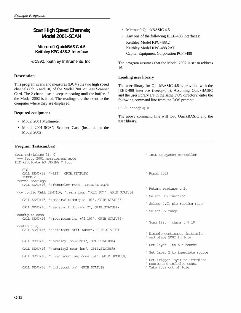
Example Programs
G-12
• Microsoft QuickBASIC 4.5
• Any one of the following IEEE-488 interfaces:
Keithley Model KPC-488.2
Keithley Model KPC-488.2AT
Capital Equipment Corporation PC<>488
The program assumes that the Model 2002 is set to address16.
Loading user library
The user library for QuickBASIC 4.5 is provided with theIEEE-488 interface (ieeeqb.qlb). Assuming QuickBASICand the user library are in the same DOS directory, enter thefollowing command line from the DOS prompt:
QB /L ieeeqb.qlb
The above command line will load QuickBASIC and theuser library.
Program (fastscan.bas)
CALL Initialize(21, 0) ' Init as system controller'--- Setup 2001 measurement modeDIM k2001data AS STRING * 1500
CLSCALL SEND(16, "*RST", GPIB.STATUS%) ' Reset 2002SLEEP 2
'format readingsCALL SEND(16, ":form:elem read", GPIB.STATUS%)
' Return readings only'dcv config CALL SEND(16, ":sens:func 'VOLT:DC'", GPIB.STATUS%)
' Select DCV functionCALL SEND(16, ":sens:volt:dc:nplc .01", GPIB.STATUS%)
' Select 0.01 plc reading rateCALL SEND(16, ":sens:volt:dc:rang 2", GPIB.STATUS%)
' Select 2V range'configure scan
CALL SEND(16, ":rout:scan:int (@5,10)", GPIB.STATUS%)' Scan list = chans 5 & 10
'config trigCALL SEND(16, ":init:cont off; :abor", GPIB.STATUS%)
' Disable continuous initiation' and place 2002 in idle
CALL SEND(16, ":arm:lay1:sour bus", GPIB.STATUS%)' Set layer 1 to bus source
CALL SEND(16, ":arm:lay2:sour imm", GPIB.STATUS%)' Set layer 2 to immediate source
CALL SEND(16, ":trig:sour imm; coun inf", GPIB.STATUS%)' Set trigger layer to immediate' source and infinite count
CALL SEND(16, ":init:cont on", GPIB.STATUS%) ' Take 2002 out of idle
Scan High Speed Channels;Model 2001-SCAN
Microsoft QuickBASIC 4.5Keithley KPC-488.2 Interface
©1992, Keithley Instruments, Inc.
Description
This program scans and measures (DCV) the two high speedchannels (ch 5 and 10) of the Model 2001-SCAN ScannerCard. The 2-channel scan keeps repeating until the buffer ofthe Model 2002 is filled. The readings are then sent to thecomputer where they are displayed.
Required equipment
• Model 2001 Multimeter
• Model 2001-SCAN Scanner Card (installed in theModel 2002)
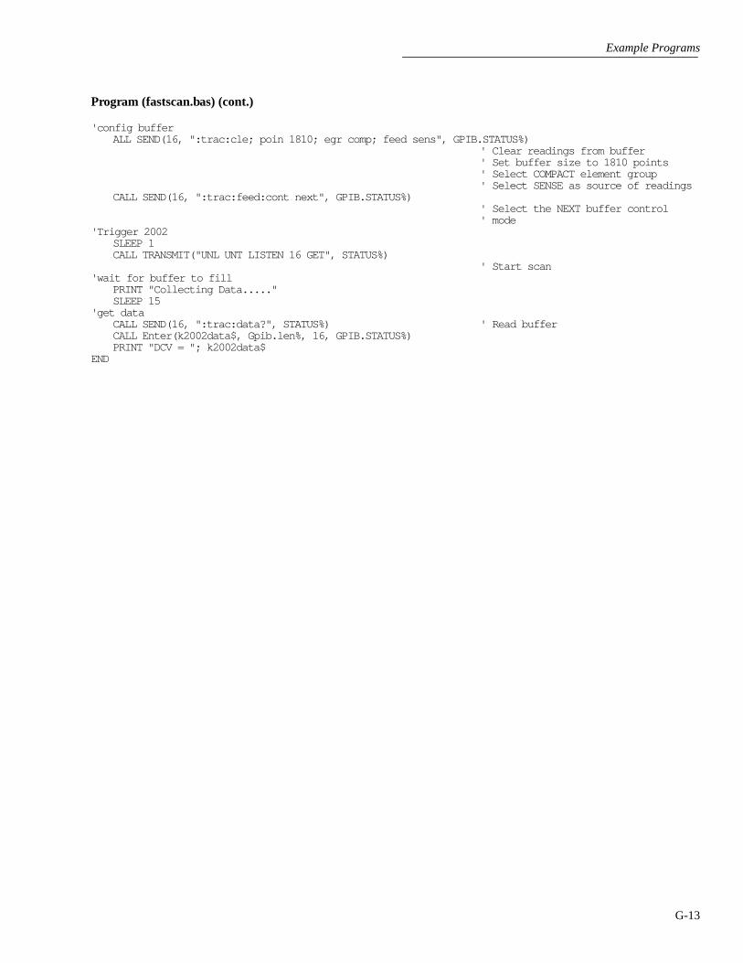
Example Programs
G-13
Program (fastscan.bas) (cont.)
'config buffer ALL SEND(16, ":trac:cle; poin 1810; egr comp; feed sens", GPIB.STATUS%)
' Clear readings from buffer' Set buffer size to 1810 points' Select COMPACT element group' Select SENSE as source of readings
CALL SEND(16, ":trac:feed:cont next", GPIB.STATUS%)' Select the NEXT buffer control' mode
'Trigger 2002SLEEP 1CALL TRANSMIT("UNL UNT LISTEN 16 GET", STATUS%)
' Start scan'wait for buffer to fill
PRINT "Collecting Data....."SLEEP 15
'get dataCALL SEND(16, ":trac:data?", STATUS%) ' Read bufferCALL Enter(k2002data$, Gpib.len%, 16, GPIB.STATUS%)PRINT "DCV = "; k2002data$
END
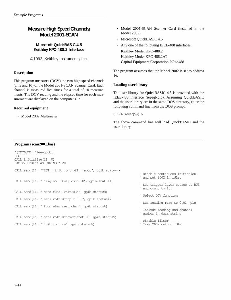
Example Programs
G-14
Measure High Speed Channels;Model 2001-SCAN
Microsoft QuickBASIC 4.5Keithley KPC-488.2 Interface
©1992, Keithley Instruments, Inc.
Description
This program measures (DCV) the two high speed channels(ch 5 and 10) of the Model 2001-SCAN Scanner Card. Eachchannel is measured five times for a total of 10 measure-ments. The DCV reading and the elapsed time for each mea-surement are displayed on the computer CRT.
Required equipment
• Model 2002 Multimeter
• Model 2001-SCAN Scanner Card (installed in theModel 2002)
• Microsoft QuickBASIC 4.5
• Any one of the following IEEE-488 interfaces:
Keithley Model KPC-488.2
Keithley Model KPC-488.2AT
Capital Equipment Corporation PC<>488
The program assumes that the Model 2002 is set to address16.
Loading user library
The user library for QuickBASIC 4.5 is provided with theIEEE-488 interface (ieeeqb.qlb). Assuming QuickBASICand the user library are in the same DOS directory, enter thefollowing command line from the DOS prompt:
QB /L ieeeqb.qlb
The above command line will load QuickBASIC and theuser library.
Program (scan2001.bas)
'$INCLUDE: 'ieeeqb.bi'CLSCALL initialize(21, 0)DIM k2002data AS STRING * 20
CALL send(16, "*RST; :init:cont off; :abor", gpib.status%)' Disable continuous initiation' and put 2002 in idle.
CALL send(16, ":trig:sour bus; coun 10", gpib.status%)' Set trigger layer source to BUS' and count to 10.
CALL send(16, ":sens:func 'Volt:DC'", gpib.status%)' Select DCV function
CALL send(16, ":sens:volt:dc:nplc .01", gpib.status%)' Set reading rate to 0.01 nplc
CALL send(16, ":form:elem read,chan", gpib.status%)' Include reading and channel' number in data string
CALL send(16, ":sens:volt:dc:aver:stat 0", gpib.status%)' Disable filter
CALL send(16, ":init:cont on", gpib.statsu%) ' Take 2002 out of idle

Example Programs
G-15
Program (scan2001.bas)
FOR x = 1 TO 5T1 = TIMERCALL send(16, ":rout:clos (@5)", gpib.status%) ' Close channel 5CALL transmit("UNL UNT LISTEN 16 GET", gpib.status%)
' Trigger a measurementCALL send(16, "fetch?", gpib.status%) ' Fetch readingCALL enter(k2002data$, gpib.len%, 16, gpib.status%)PRINT "DCV="; k2002data$ ' Display readingT2 = TIMERT3 = T2 - T1PRINT "It took "; T3; " seconds"
CALL send(16, ":rout:clos (@10)", gpib.status%)' Close channel 10
CALL transmit("UNL UNT LISTEN 16 GET", gpib.status%)' Trigger a measurement
CALL send(16, "fetch?", gpib.status%) ' Fetch readingCALL enter(k2002data$, gpib.len%, 16, gpib.status%)PRINT "DCV="; k2002data$= ' Display readingT2 = TIMERT3 = T2 - T1PRINT "It took "; T3; " seconds" ' Display time it took to take
' readingNEXT xEND

Example Programs
G-16
• RTD Temperature Sensor (connected to channel 4 ofthe scanner card)
• Microsoft QuickBASIC 4.5
• Any one of the following IEEE-488 interfaces:
Keithley Model KPC-488.2
Keithley Model KPC-488.2AT
Capital Equipment Corporation PC<>488
The program assumes that the Model 2002 is set to address16.
Loading user library
The user library for QuickBASIC 4.5 is provided with theIEEE-488 interface (ieeeqb.qlb). Assuming QuickBASICand the user library are in the same DOS directory, enter thefollowing command line from the DOS prompt:
QB /L ieeeqb.qlb
The above command line will load QuickBASIC and theuser library.
Program (2001scrd.bas)
CLSFOR I = 1 TO 5
CALL SEND(16, ":form:elem read", GPIB.STATUS%) ' Include only the readings' in the data string
CALL SEND(16, ":sens:func 'RES'", GPIB.STATUS%) ' Select the ohms functionCALL SEND(16, ":rout:clos (@2)", GPIB.STATUS%) ' Close channel 2CALL SEND(16, ":fetch?", GPIB.STATUS%) ' Fetch readingCALL Enter(k2002data$, Gpib.len%, 16, GPIB.STATUS%)PRINT "RES ="; k2002data$ ' Print readingCALL SEND(16, ":sens:func 'TEMP'", GPIB.STATUS%) ' Select the temperature
' functionCALL SEND(16, ":rout:clos (@4)", GPIB.STATUS%) ' Close channel 4CALL SEND(16, ":fetch?", GPIB.STATUS%) ' Fetch readingCALL Enter(k2002data$, Gpib.len%, 16, GPIB.STATUS%)PRINT "TEMP = "; k2002data$ ' Display reading
NEXT IEND
Scan Two Channels; Model 2001-SCAN
Microsoft QuickBASIC 4.5Keithley KPC-488.2 Interface
©1992, Keithley Instruments, Inc.
Description
This program scans and measures two channels of the Model2001-SCAN Scanner Card. Channel 2 is configured for Ω2measurements and channel 4 is configured for RTD temper-ature measurements. The scan is performed five times for atotal of 10 measurements. The 10 readings are displayed onthe computer CRT.
Required equipment
• Model 2002 Multimeter
• Model 2001-SCAN Scanner Card (installed in theModel 2002)
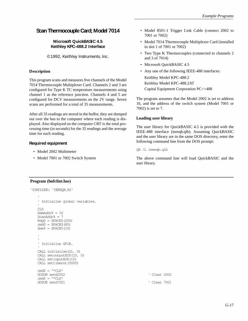
Example Programs
G-17
• Model 8501-1 Trigger Link Cable (connect 2002 to7001 or 7002)
• Model 7014 Thermocouple Multiplexer Card (installedin slot 1 of 7001 or 7002)
• Two Type K Thermocouples (connected to channels 2and 3 of 7014)
• Microsoft QuickBASIC 4.5
• Any one of the following IEEE-488 interfaces:
Keithley Model KPC-488.2
Keithley Model KPC-488.2AT
Capital Equipment Corporation PC<>488
The program assumes that the Model 2002 is set to address16, and the address of the switch system (Model 7001 or7002) is set to 7.
Loading user library
The user library for QuickBASIC 4.5 is provided with theIEEE-488 interface (ieeeqb.qlb). Assuming QuickBASICand the user library are in the same DOS directory, enter thefollowing command line from the DOS prompt:
QB /L ieeeqb.qlb
The above command line will load QuickBASIC and theuser library.
Program (bufclint.bas)
'$INCLUDE: 'IEEEQB.BI'
'' Initialize global variables.'CLSDmmAddr% = 16ScanAddr% = 7Rdg$ = SPACE$(200)cmd$ = SPACE$(80)Sme$ = SPACE$(10)
''' Initialize GPIB.'CALL initialize(21, 0)CALL setoutputEOS(10, 0)CALL setinputEOS(10)CALL settimeout(5000)
cmd$ = "*CLS"GOSUB send2002 ' Clear 2002cmd$ = "*CLS"GOSUB send7001 ' Clear 7001
Scan Thermocouple Card; Model 7014
Microsoft QuickBASIC 4.5Keithley KPC-488.2 Interface
©1992, Keithley Instruments, Inc.
Description
This program scans and measures five channels of the Model7014 Thermocouple Multiplexer Card. Channels 2 and 3 areconfigured for Type K TC temperature measurements usingchannel 1 as the reference junction. Channels 4 and 5 areconfigured for DCV measurements on the 2V range. Sevenscans are performed for a total of 35 measurements.
After all 35 readings are stored in the buffer, they are dumpedout over the bus to the computer where each reading is dis-played. Also displayed on the computer CRT is the total pro-cessing time (in seconds) for the 35 readings and the averagetime for each reading.
Required equipment
• Model 2002 Multimeter
• Model 7001 or 7002 Switch System

Example Programs
G-18
Program (bufclint.bas) (cont.)
' Idle 2002 and 7001.'cmd$ = "*RST; :init:cont off"GOSUB send2002 ' Reset 2002 and disable continuous
' initiationcmd$ = ":abor"GOSUB send2002 ' Place 2002 in idlecmd$ = "*RST; :init:cont off"GOSUB send7001 ' Reset 7001 and disable continuous
' initiationcmd$ = ":abor"GOSUB send7001 ' Place 7001 in idle
'' Initialize 2002.' cmd$ = ":syst:azer:stat on"GOSUB send2002 ' Enable auto zerocmd$ = ":form:elem read"GOSUB send2002 ' Use only the reading in the data
' stringcmd$ = ":sens:volt:dc:nplc .01"GOSUB send2002 ' Set DCV reading rate for 0.01 nplccmd$ = ":sens:volt:dc:rang 1"GOSUB send2002 ' Select 2V rangecmd$ = ":sens:func 'temp'"GOSUB send2002 ' Select TEMP functioncmd$ = ":sens:temp:aver:stat off"GOSUB send2002 ' Disable filtercmd$ = ":sens:temp:nplc .01"GOSUB send2002 ' Set TEMP reading rate for 0.01 nplccmd$ = ":rout:scan:ext:func (@1),'rjun1'"GOSUB send2002 ' Assign RJUN1 to external channel 1cmd$ = ":rout:scan:ext:func (@2,3),'temp'"GOSUB send2002 ' Assign TEMP to channels 2 and 3cmd$ = ":rout:scan:ext:func (@4,5),'volt:dc'"GOSUB send2002 ' Assign DCV to channels 4 and 5cmd$ = ":rout:scan:ext (@1:5)"GOSUB send2002 ' External scan list = chans 1 thru 5
'Set up TC parameters
cmd$ = ":temp:tran tc"GOSUB send2002 ' Select TC transducer typecmd$ = ":temp:tc:type k"GOSUB send2002 ' Specify K type TC transducercmd$ = ":temp:rjun1:rsel real"GOSUB send2002 ' Select REAL reference typecmd$ = ":rout:clos (@1!1)"GOSUB send7001 ' Close channel 1!1cmd$ = ":temp:rjun1:real:offs 0.05463"GOSUB send2002 ' Set 0 C voltage offset to 0.05463Vcmd$ = ":temp:rjun1:real:tco .0002"GOSUB send2002 ' Set temperature coefficient to 0.0002cmd$ = ":temp:rjun1:acq"GOSUB send2002 ' Update reference temperature SLEEP 1cmd$ = ":rout:open (@1!1)"GOSUB send7001 ' Open channel 1!1cmd$ = ":arm:lay1:sour imm"GOSUB send2002 ' Set arm layer 1 source to Immediatecmd$ = ":arm:lay2:sour imm"GOSUB send2002 ' Set arm layer 2 source to Immediatecmd$ = ":trig:sour tlin"GOSUB send2002 ' Set trigger layer source to Triglink

Example Programs
G-19
Program (bufclint.bas) (cont.)
cmd$ = ":trig:tcon:asyn:ilin 2; olin 1"GOSUB send2002 ' Select Triglink lines; input = line
' #2, output = line #1cmd$ = "trig:tcon:dir sour"GOSUB send2002 ' Enable source bypass for trigger
' layercmd$ = ":arm:lay1:coun 1"GOSUB send2002 ' Set arm layer 1 count to 1cmd$ = ":arm:lay2:coun 1"GOSUB send2002 ' Set arm layer 2 count to 1cmd$ = ":trig:coun 35"GOSUB send2002 ' Set trigger layer count to 35cmd$ = ":arm:lay2:del 0"GOSUB send2002 ' Set arm layer 2 delay to zerocmd$ = ":trig:del 0"GOSUB send2002 ' Set trigger layer delay to zero
' Initialize 7001.cmd$ = ":rout:open all"GOSUB send7001 ' Open all channelscmd$ = ":rout:scan (@1!1:1!5)"GOSUB send7001 ' Scan list = chans 1!1 thru 1!5cmd$ = ":arm:lay1:sour imm"GOSUB send7001 ' Set arm layer 1 source to Immediatecmd$ = ":arm:lay2:sour imm"GOSUB send7001 ' Set arm layer 2 source to Immediatecmd$ = ":trig:sour tlin"GOSUB send7001 ' Set trigger layer source to Triglinkcmd$ = ":trig:tcon:asyn:ilin 1; olin 2"GOSUB send7001 ' Select Triglink lines; input = line
' #1, output = line #2cmd$ = ":arm:lay1:coun 1"GOSUB send7001 ' Set arm layer 1 count to 1cmd$ = ":arm:lay2:coun 1"GOSUB send7001 ' Set arm layer 2 count to 1cmd$ = ":trig:coun 35"GOSUB send7001 ' Set trigger layer count to 35cmd$ = ":arm:lay2:del 0"GOSUB send7001 ' Set arm layer 2 delay to zerocmd$ = ":trig:del 0"GOSUB send7001 ' Set trigger layer delay to zerocmd$ = ":trig:tcon:dir sour"GOSUB send7001 ' Enable source bypass of trigger
' layer
' Arm buffer.cmd$ = "*SRE 1"GOSUB send2002 ' Set MSB bit of SRE registercmd$ = "stat:meas:ptr 32767; ntr 0; enab 512"GOSUB send2002 ' Set all PTR bits and clear all NTR
' bits for measurement events' Set Buffer Full bit of Measurement' Event Enable Register
cmd$ = ":trac:feed calc"GOSUB send2002 ' Select Calculate as reading sourcecmd$ = ":trac:poin 35"GOSUB send2002 ' Set buffer size to 35 pointscmd$ = ":trac:egr full"GOSUB send2002 ' Select Full element groupcmd$ = ":form:data sre"GOSUB send2002 ' Select IEEE754 single precision data
' format

Example Programs
G-20
Program (bufclint.bas) (cont.)
cmd$ = ":trac:feed:cont next; *OPC"GOSUB send2002 ' Select Next buffer control mode
' Set OPC upon completion of commandscmd$ = ":rout:scan:lsel ext"GOSUB send2002 ' Select external scan mode
'trigger equipmentcmd$ = ":init"GOSUB send7001 ' Take 7001 out of idlecmd$ = ":init"GOSUB send2002 ' Take 2002 out of idle
'' Start filling....'t1 = TIMER' Wait for buffer to fill...'DO
DOLOOP UNTIL srq%
CALL spoll(DmmAddr%, poll%, status%)LOOP UNTIL (poll% AND 64) ' Loop until buffer fillscmd$ = ":stat:meas:even?"GOSUB send2002CALL enter(Sme$, length%, 16, status%)
'' Go get buffer contents.'cmd$ = "trac:data?"GOSUB send2002 ' Read all readings in bufferDIM Readings!(1 TO 350), dummy!(1 TO 1)' Setup CEC for LISTEN & 2002 for TALKCALL transmit("UNT UNL MLA TALK 16", status%)' Read 2 bytes (#0)r$ = SPACE$(2)CALL receive(r$, l%, status%)
NumDataPoints% = 35' Get Data in 4 blocks since CEC can only handle up to 64kB' per data transfer.NumBytes% = NumDataPoints% * 4CALL rarray(Readings!(1), NumBytes%, l%, status%)' get Terminator Character(s)CALL settimeout(100)CALL rarray(dummy!(1), 1, l%, status%)CALL settimeout(10000)CALL transmit("UNT UNL", status%) ' UNTalk and UNListen all devicest2 = TIMERt3 = t2 - t1FOR i = 1 TO 35PRINT "Rdg("; i; ") = "; Readings!(i) ' Display readingNEXT iPRINTPRINT "Total time = "; t3 ' Display total processing time
' for all readingsPRINTt4 = t3 / 35PRINT "Seconds per channel = "; t4 ' Display the average time for each
' readingEND

Example Programs
G-21
Program (bufclint.bas) (cont.)
send2002:CALL send(DmmAddr%, cmd$, status%)
RETURN
send7001:CALL send(ScanAddr%, cmd$, status%)
RETURN
H
HP3458A Emulation Mode
H-1
Introduction
This appendix provides detailed information on using theModel 2002 HP3458A emulation mode. The emulationmode gives the Model 2002 a high degree of compatibilitywith the Hewlett-Packard HP3458A Digital Multimeter,allowing the instrument to be substituted for an HP3458A inan existing measurement system with little or no programmodifications.
Firmware revision level
The HP3458A emulation mode is available in Model 2002sequipped with revision A05 and later main processor firm-ware. The firmware revision level is displayed during thepower-up cycle and may be displayed at any time by usingthe GENERAL/ SERIAL # selection in the main MENU.
Enabling the HP3458A emulation mode
The HP3458A emulation mode may be enabled from thefront panel by using the LANGUAGE selection in the GPIBmenu as follows:
1. Press the MENU key to display the main menu.
2. Select GPIB, then press ENTER.
3. Select LANGUAGE, then press ENTER.
4. Choose HP3458-EMULATION, then press ENTER.
5. Enable or disable the emulation mode as desired, thenpress ENTER to complete your selection.
6. Press EXIT as required to return to normal display.
Unsupported commands
Table H-1 summarizes commands not supported by theModel 2002 HP3458A emulation mode.
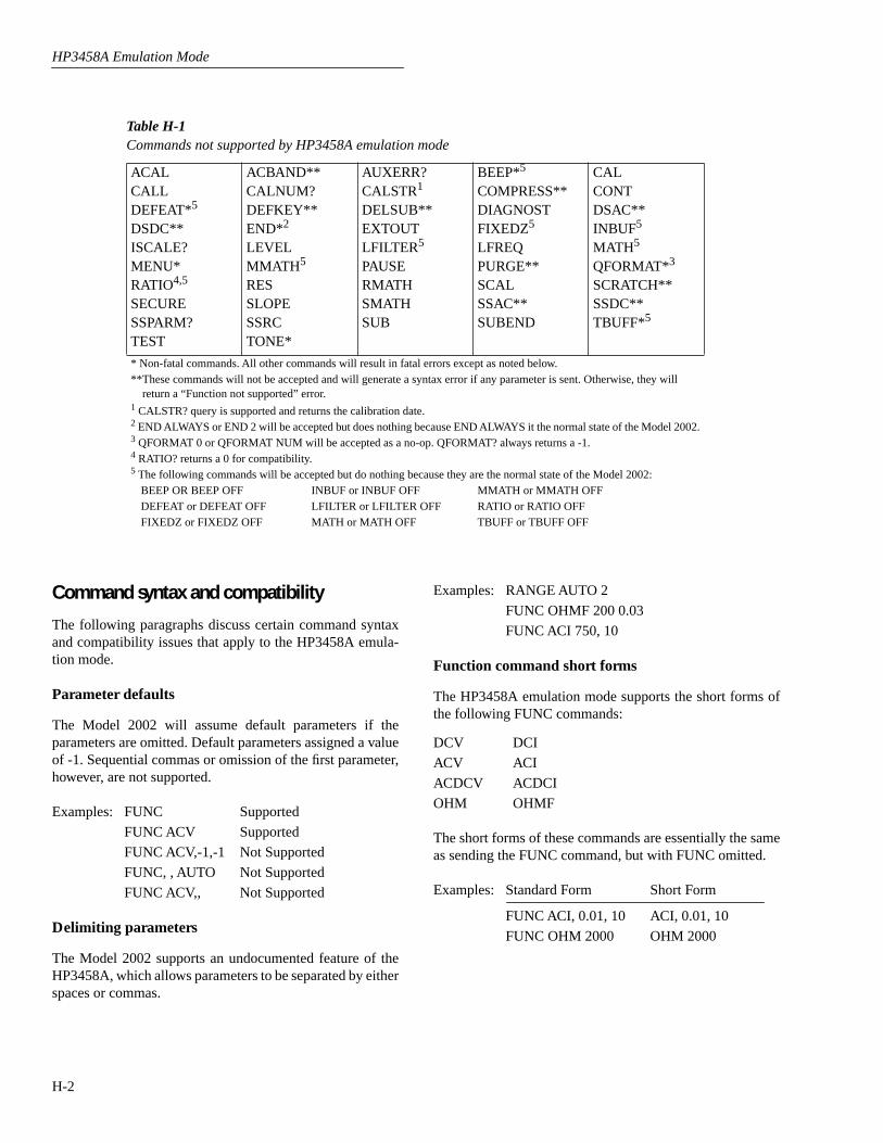
HP3458A Emulation Mode
H-2
Command syntax and compatibility
The following paragraphs discuss certain command syntaxand compatibility issues that apply to the HP3458A emula-tion mode.
Parameter defaults
The Model 2002 will assume default parameters if theparameters are omitted. Default parameters assigned a valueof -1. Sequential commas or omission of the first parameter,however, are not supported.
Examples: FUNC Supported
FUNC ACV Supported
FUNC ACV,-1,-1 Not Supported
FUNC, , AUTO Not Supported
FUNC ACV,, Not Supported
Delimiting parameters
The Model 2002 supports an undocumented feature of theHP3458A, which allows parameters to be separated by eitherspaces or commas.
Table H-1Commands not supported by HP3458A emulation mode
ACALCALLDEFEAT*5
DSDC**ISCALE?MENU*RATIO4,5
SECURESSPARM?TEST
ACBAND**CALNUM?DEFKEY**END*2
LEVELMMATH 5
RESSLOPESSRCTONE*
AUXERR?CALSTR1
DELSUB**EXTOUTLFILTER5
PAUSERMATHSMATHSUB
BEEP*5
COMPRESS**DIAGNOSTFIXEDZ5
LFREQPURGE**SCALSSAC**SUBEND
CALCONTDSAC**INBUF5
MATH5
QFORMAT*3
SCRATCH**SSDC**TBUFF*5
* Non-fatal commands. All other commands will result in fatal errors except as noted below.**These commands will not be accepted and will generate a syntax error if any parameter is sent. Otherwise, they will
return a “Function not supported” error.1 CALSTR? query is supported and returns the calibration date.2 END ALWAYS or END 2 will be accepted but does nothing because END ALWAYS it the normal state of the Model 2002.3 QFORMAT 0 or QFORMAT NUM will be accepted as a no-op. QFORMAT? always returns a -1.4 RATIO? returns a 0 for compatibility.5 The following commands will be accepted but do nothing because they are the normal state of the Model 2002:
BEEP OR BEEP OFF INBUF or INBUF OFF MMATH or MMATH OFFDEFEAT or DEFEAT OFF LFILTER or LFILTER OFF RATIO or RATIO OFFFIXEDZ or FIXEDZ OFF MATH or MATH OFF TBUFF or TBUFF OFF
Examples: RANGE AUTO 2
FUNC OHMF 200 0.03
FUNC ACI 750, 10
Function command short forms
The HP3458A emulation mode supports the short forms ofthe following FUNC commands:
DCV DCI
ACV ACI
ACDCV ACDCI
OHM OHMF
The short forms of these commands are essentially the sameas sending the FUNC command, but with FUNC omitted.
Examples: Standard Form Short Form
FUNC ACI, 0.01, 10 ACI, 0.01, 10
FUNC OHM 2000 OHM 2000
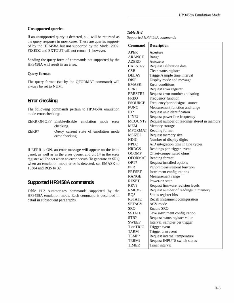
HP3458A Emulation Mode
H-3
Unsupported queries
If an unsupported query is detected, a -1 will be returned asthe query response in most cases. These are queries support-ed by the HP3458A but not supported by the Model 2002.FIXED2 and EXTOUT will not return -1, however.
Sending the query form of commands not supported by theHP3458A will result in an error.
Query format
The query format (set by the QFORMAT command) willalways be set to NUM.
Error checking
The following commands pertain to HP3458A emulationmode error checking:
EERR ON|OFF Enable/disable emulation mode errorchecking.
EERR? Query current state of emulation modeerror checking.
If EERR is ON, an error message will appear on the frontpanel, as well as in the error queue, and bit 14 in the errorregister will be set when an error occurs. To generate an SRQwhen an emulation mode error is detected, set EMASK to16384 and RQS to 32.
Supported HP3458A commands
Table H-2 summarizes commands supported by theHP3458A emulation mode. Each command is described indetail in subsequent paragraphs.
Table H-2
Supported HP3458A commands
Command Description
APERARANGEAZEROCALSTR?CSBDELAYDISPEMASKERR?ERRSTR?FREQFSOURCEFUNCID?LINE?MCOUNT?MEMMFORMATMSIZE?NDIGNPLCNRDGSOCOMPOFORMATOPT?PERPRESETRANGERESETREV?RMEM?RQSRSTATESETACVSRQSSTATESTB?SWEEPT or TRIGTARMTEMP?TERM?TIMER
ApertureRangeAutozeroRequest calibration dateClear status registerTrigger/sample time intervalDisplay mode and messageError conditionsRequest error registerRequest error number and stringFrequency functionFrequency/period signal sourceMeasurement function and rangeRequest unit identificationRequest power line frequencyRequest number of readings stored in memoryMemory storageReading formatRequest memory sizeNumber of display digitsA/D integration time in line cyclesReadings per trigger, eventOffset-compensated ohmsReading formatRequest installed optionsPeriod measurement functionInstrument configurationsMeasurement rangePower-on stateRequest firmware revision levelsRequest number of readings in memoryStatus register bitsRecall instrument configurationACV modeEnable SRQSave instrument configurationRequest status register valueInterval, samples per triggerTrigger eventTrigger arm eventRequest internal temperatureRequest INPUTS switch statusTimer interval
HP3458A Emulation Mode
H-4
APER
Purpose
To program the A/D integration time.
Format
APER <aperture>
Parameter
<aperture>
= 166.67E-6s to 1s
Default
1.67E-4s
Query
APER?
Returns aperture in seconds.
Description
The
APER
command programs the Model 2002 A/D integration period. The unit will accept valuesbetween 0s and 1s, but it rounds values to meet the Model 2002’s valid parameter range.
Example
APER 1E-3
Program 1ms aperture.
ARANGE
Purpose
To enable/disable the autorange mode.
Format
ARANGE <range>
Parameter
<range>
<range> Parameter Numeric Equivalent Description
OFF 0 Disable autorange.ON 1 Enable autorange.ONCE 2 Autorange next reading.
Default
OFF
Query
ARANGE?
Returns autorange status.
Description
ARANGE
enables/disables autorange mode. The valid parameters are OFF, ON, and ONCE, whichcorrespond numerically to 0, 1, and 2 respectively.
Purpose
Autorange can also be controlled by the
FUNC
and
RANGE
commands. Specifying AUTO for the sec-ond parameter of the
FUNC
command turns autoranging ON. Specifying AUTO for the first parameterof the
RANGE
command turns autoranging ON.
Example
ARANGE ON
Enable autorange.
ARANGE 0
Disable autorange.
AZERO
Purpose
To enable/disable the autozero mode.
Format
AZERO <mode>
Parameter
<mode>
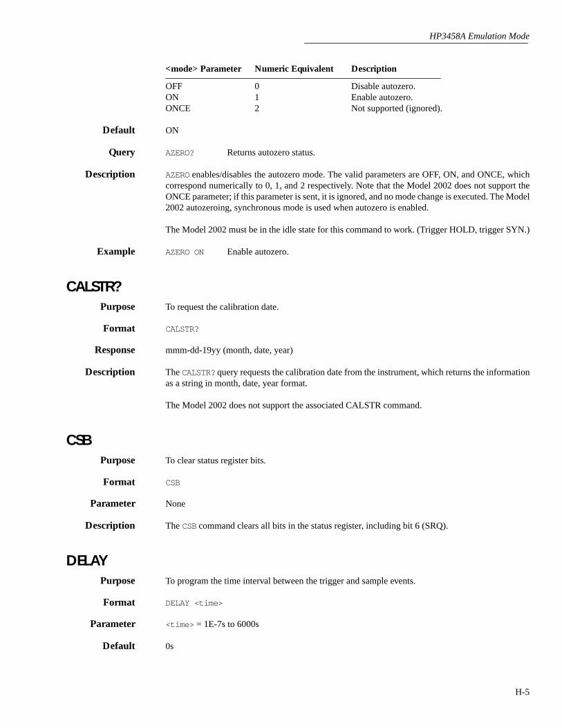
HP3458A Emulation Mode
H-5
<mode> Parameter Numeric Equivalent Description
OFF 0 Disable autozero.ON 1 Enable autozero.ONCE 2 Not supported (ignored).
Default
ON
Query
AZERO?
Returns autozero status.
Description
AZERO
enables/disables the autozero mode. The valid parameters are OFF, ON, and ONCE, whichcorrespond numerically to 0, 1, and 2 respectively. Note that the Model 2002 does not support theONCE parameter; if this parameter is sent, it is ignored, and no mode change is executed. The Model2002 autozeroing, synchronous mode is used when autozero is enabled.
The Model 2002 must be in the idle state for this command to work. (Trigger HOLD, trigger SYN.)
Example
AZERO ON
Enable autozero.
CALSTR?
Purpose
To request the calibration date.
Format
CALSTR?
Response
mmm-dd-19yy (month, date, year)
Description
The
CALSTR?
query requests the calibration date from the instrument, which returns the informationas a string in month, date, year format.
The Model 2002 does not support the associated CALSTR command.
CSB
Purpose
To clear status register bits.
Format
CSB
Parameter
None
Description
The
CSB
command clears all bits in the status register, including bit 6 (SRQ).
DELAY
Purpose
To program the time interval between the trigger and sample events.
Format
DELAY <time>
Parameter
<time>
= 1E-7s to 6000s
Default
0s
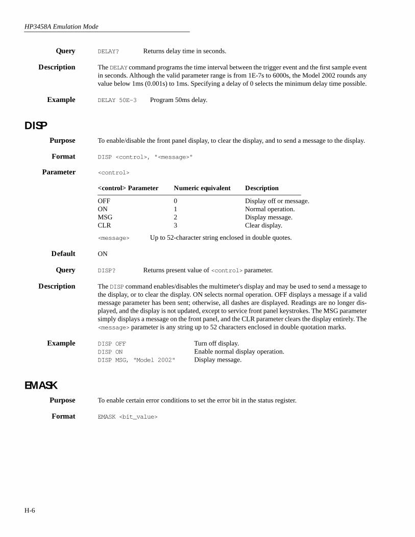
HP3458A Emulation Mode
H-6
Query DELAY? Returns delay time in seconds.
Description The DELAY command programs the time interval between the trigger event and the first sample eventin seconds. Although the valid parameter range is from 1E-7s to 6000s, the Model 2002 rounds anyvalue below 1ms (0.001s) to 1ms. Specifying a delay of 0 selects the minimum delay time possible.
Example DELAY 50E-3 Program 50ms delay.
DISP Purpose To enable/disable the front panel display, to clear the display, and to send a message to the display.
Format DISP <control>, "<message>"
Parameter <control>
<control> Parameter Numeric equivalent Description
OFF 0 Display off or message.ON 1 Normal operation.MSG 2 Display message.CLR 3 Clear display.
<message> Up to 52-character string enclosed in double quotes.
Default ON
Query DISP? Returns present value of <control> parameter.
Description The DISP command enables/disables the multimeter's display and may be used to send a message tothe display, or to clear the display. ON selects normal operation. OFF displays a message if a validmessage parameter has been sent; otherwise, all dashes are displayed. Readings are no longer dis-played, and the display is not updated, except to service front panel keystrokes. The MSG parametersimply displays a message on the front panel, and the CLR parameter clears the display entirely. The<message> parameter is any string up to 52 characters enclosed in double quotation marks.
Example DISP OFF Turn off display.DISP ON Enable normal display operation.DISP MSG, "Model 2002" Display message.
EMASKPurpose To enable certain error conditions to set the error bit in the status register.
Format EMASK <bit_value>
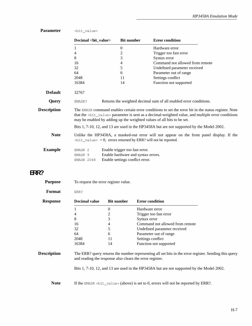
HP3458A Emulation Mode
H-7
Parameter <bit_value>
Decimal <bit_value> Bit number Error condition
1 0 Hardware error4 2 Trigger too fast error8 3 Syntax error16 4 Command not allowed from remote32 5 Undefined parameter received64 6 Parameter out of range2048 11 Settings conflict16384 14 Function not supported
Default 32767
Query EMASK? Returns the weighted decimal sum of all enabled error conditions.
Description The EMASK command enables certain error conditions to set the error bit in the status register. Notethat the <bit_value> parameter is sent as a decimal-weighted value, and multiple error conditionsmay be enabled by adding up the weighted values of all bits to be set.
Bits 1, 7-10, 12, and 13 are used in the HP3458A but are not supported by the Model 2002.
Note Unlike the HP3458A, a masked-out error will not appear on the front panel display. If the<bit_value> = 0, errors returned by ERR? will not be reported.
Example EMASK 2 Enable trigger too fast error.EMASK 9 Enable hardware and syntax errors.EMASK 2048 Enable settings conflict error.
ERR?Purpose To request the error register value.
Format ERR?
Response Decimal value Bit number Error condition
1 0 Hardware error4 2 Trigger too fast error8 3 Syntax error16 4 Command not allowed from remote32 5 Undefined parameter received64 6 Parameter out of range2048 11 Settings conflict16384 14 Function not supported
Description The ERR? query returns the number representing all set bits in the error register. Sending this queryand reading the response also clears the error register.
Bits 1, 7-10, 12, and 13 are used in the HP3458A but are not supported by the Model 2002.
Note If the EMASK <bit_value> (above) is set to 0, errors will not be reported by ERR?.

HP3458A Emulation Mode
H-8
ERRSTR?Purpose To request the error number and error response string.
Format ERRSTR?
Response <error_number>, <error_string>
Description The ERRSTR? query returns two responses separated by a comma. The first response is the error num-ber, and the second is the message explaining the error.
Unlike the HP3458, Model 2002 errors are returned in the order generated instead of the error reg-ister bit order. No error register bits are cleared until the last error is read at which time all bits arecleared.
FREQPurpose To select the frequency measurement function.
Format FREQ <max_input>,<%_resolution>
Parameter <max_input> 1V, 10V, or 100V<%_resolution> Ignored
Description The FREQ command selects the frequency measurement mode for the Model 2002. The first param-eter selects a maximum input level of 1V, 10V, or 100V, while the second parameter is not supportedby the Model 2002 and will be ignored.
Example FREQ Select frequency.FREQ 10 Select frequency, 10V maximum input.
FSOURCE Purpose To select the signal type for frequency or period measurements.
Format FSOURCE <source>
Parameter <source>
<source> parameter Numeric equivalent Description
ACV 2 AC voltageACDCV 3 AC+DC voltageACI 7 AC currentACDCI 8 AC+DC current
Default ACV
Query FSOURCE? Returns the present frequency source.
Description The FSOURCE command specifies the type of signal to be used as the input signal for frequency orperiod measurements. Signal types include AC voltage, AC current, AC+DC voltage, and AC+DCcurrent.

HP3458A Emulation Mode
H-9
Example FSOURCE ACV Select AC voltage source.FSOURCE ACDCI Select AC+DC current source.
FUNCPurpose To select the measurement function and range.
Format FUNC <function> ,<max_input>, <%_resolution>
Parameter <function>
<function> Parameter Numeric Equivalent Description
DCV 1 DC voltageACV 2 AC voltageACDCV 3 DC-coupled AC voltsOHM 4 2-wire resistanceOHMF 5 4-wire resistanceDCI 6 DC currentACI 7 AC currentACDCI 8 DC-coupled AC currentFREQ 9 FrequencyPER 10 Period
<max_input> AUTO for autorange or full-range value
<%_resolution> Ignored
Default DCV, AUTO
Query FUNC? Returns two responses separated by a comma: (1) the present measurement func-tion, and (2) that function's present range.
Description The FUNC command selects the type of measurement for the Model 2002. It also allows you to spec-ify the measurement range for the respective function. (See paragraph 3.18 for details on ranges forthe various measurement functions.) The <%_resolution> parameter is not supported by the Model2002 and will be ignored.
Notes 1. The FUNC header may be omitted when programming the function.2. All HP3458A functions not listed above are not supported by the Model 2002.
Example FUNC DCV Select DCV function.FUNC ACV, AUTO Select ACV function, autorange.DCI, AUTO Select DCI function without using header.
ID?Purpose To request the instrument's identification string.
Format ID?
Response HP3458A
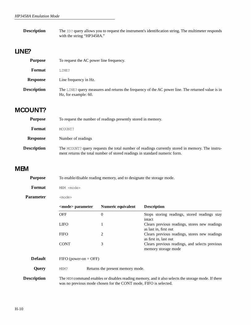
HP3458A Emulation Mode
H-10
Description The ID? query allows you to request the instrument's identification string. The multimeter respondswith the string “HP3458A.”
LINE?Purpose To request the AC power line frequency.
Format LINE?
Response Line frequency in Hz.
Description The LINE? query measures and returns the frequency of the AC power line. The returned value is inHz, for example: 60.
MCOUNT?Purpose To request the number of readings presently stored in memory.
Format MCOUNT?
Response Number of readings
Description The MCOUNT? query requests the total number of readings currently stored in memory. The instru-ment returns the total number of stored readings in standard numeric form.
MEMPurpose To enable/disable reading memory, and to designate the storage mode.
Format MEM <mode>
Parameter <mode>
<mode> parameter Numeric equivalent Description
OFF 0 Stops storing readings, stored readings stayintact
LIFO 1 Clears previous readings, stores new readingsas last in, first out
FIFO 2 Clears previous readings, stores new readingsas first in, last out
CONT 3 Clears previous readings, and selects previousmemory storage mode
Default FIFO (power-on = OFF)
Query MEM? Returns the present memory mode.
Description The MEM command enables or disables reading memory, and it also selects the storage mode. If therewas no previous mode chosen for the CONT mode, FIFO is selected.

HP3458A Emulation Mode
H-11
Example MEM FIFO Store as first in, last out.MEM OFF Turn off storage.
MFORMAT Purpose To clear reading memory, and to designate the storage format for new readings.
Format MFORMAT <format>
Parameter <format>
<format> parameter Numeric equivalent Description
ASCII 1 ASCIISREAL 4 Single realDREAL 5 Double real
Default SREAL
Query MFORMAT? Returns the present setting of the memory format.
Description The MFORMAT command clears reading memory and designates the storage format for new readings.Available formats include ASCII, as well as single and double real.
Unlike the HP3458A, the Model 2002 MFORMAT command does affect the OFORMAT setting. Thesetwo commands perform identical functions.
Example MFORMAT ASCII Select ASCII format.MFORMAT DREAL Select double real format.
MSIZE?Purpose To request reading memory size.
Query MSIZE? Returns two responses separated by a comma: (1) total memory size in bytes, and(2) the total amount of available memory in bytes.
Description The MSIZE? query is useful for determining total memory size and the number of memory bytes stillavailable for storage.
NDIG Purpose To program the number of display digits used for readings.
Format NDIG <#_digits>
Parameter <#_digits> 3 to 8 (3-1/2 digits to 8-1/2 digits)
Default 7 (7-1/2 digits)
Query NDIG? Returns the currently specified number of display digits.
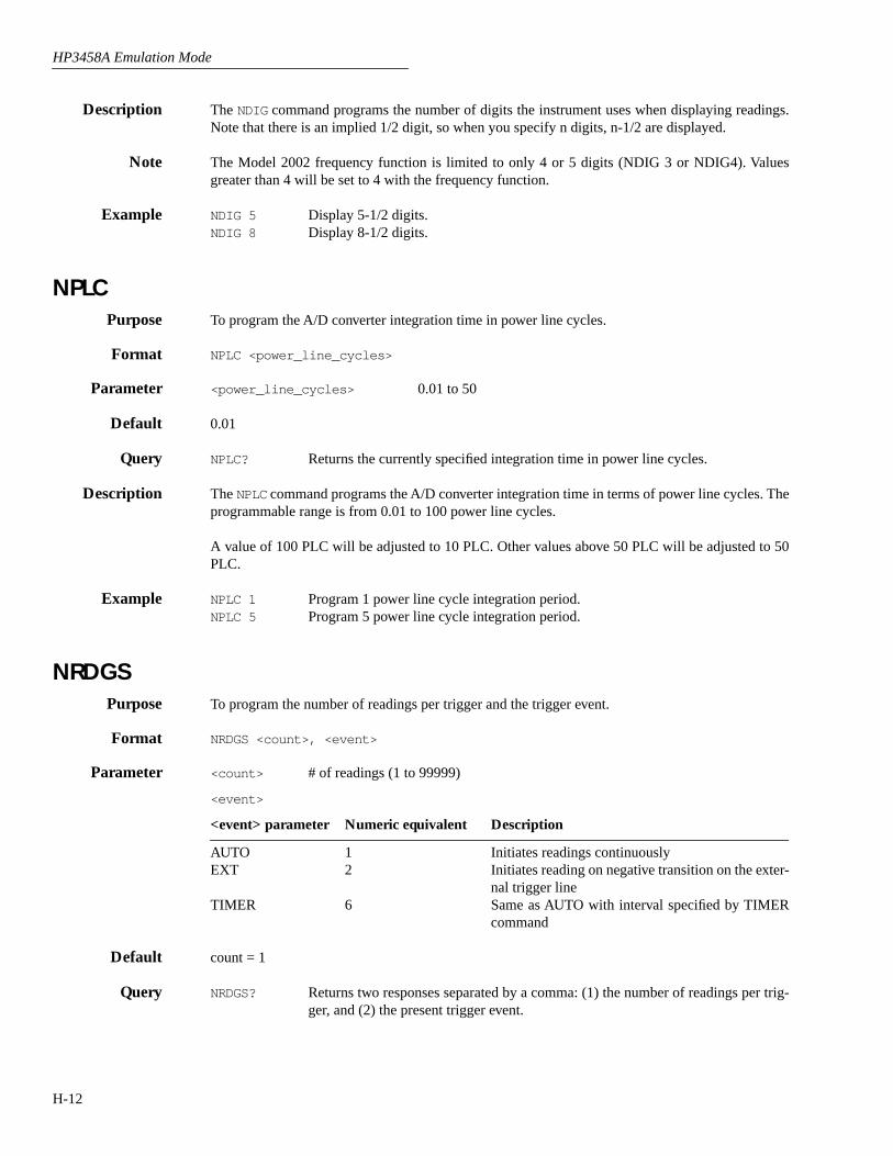
HP3458A Emulation Mode
H-12
Description The NDIG command programs the number of digits the instrument uses when displaying readings.Note that there is an implied 1/2 digit, so when you specify n digits, n-1/2 are displayed.
Note The Model 2002 frequency function is limited to only 4 or 5 digits (NDIG 3 or NDIG4). Valuesgreater than 4 will be set to 4 with the frequency function.
Example NDIG 5 Display 5-1/2 digits.NDIG 8 Display 8-1/2 digits.
NPLCPurpose To program the A/D converter integration time in power line cycles.
Format NPLC <power_line_cycles>
Parameter <power_line_cycles> 0.01 to 50
Default 0.01
Query NPLC? Returns the currently specified integration time in power line cycles.
Description The NPLC command programs the A/D converter integration time in terms of power line cycles. Theprogrammable range is from 0.01 to 100 power line cycles.
A value of 100 PLC will be adjusted to 10 PLC. Other values above 50 PLC will be adjusted to 50PLC.
Example NPLC 1 Program 1 power line cycle integration period.NPLC 5 Program 5 power line cycle integration period.
NRDGSPurpose To program the number of readings per trigger and the trigger event.
Format NRDGS <count>, <event>
Parameter <count> # of readings (1 to 99999)
<event>
<event> parameter Numeric equivalent Description
AUTO 1 Initiates readings continuouslyEXT 2 Initiates reading on negative transition on the exter-
nal trigger lineTIMER 6 Same as AUTO with interval specified by TIMER
command
Default count = 1
Query NRDGS? Returns two responses separated by a comma: (1) the number of readings per trig-ger, and (2) the present trigger event.

HP3458A Emulation Mode
H-13
Description The NRDGS command programs the number of readings per trigger as well as the event that initiatesthe trigger. Available events include continuous, external trigger, the GPIB talk command, as well astimer events.
All other HP3458A trigger events are not supported by the Model 2002.
Example NRDGS 10, SYN Take 10 readings per talk command.NRDGS 100, EXT Take 100 readings per external trigger event.
OCOMPPurpose To enable or disable the offset-compensated ohms mode.
Format OCOMP <control>
Parameter <control>
<control> parameter Numeric equivalent Description
OFF 0 Offset-compensated ohms offON 1 Offset-compensated ohms on
Default ON (power-on default = OFF)
Query OCOMP? Returns the current offset-compensated ohms state.
Description The OCOMP command enables/disables the offset-compensated ohms function.
Example OCOMP ON Enable offset-compensated ohms.
OFORMATPurpose To program the data format for both normal and memory readings.
Format OFORMAT <format>
Parameter <format>
<format> parameter Numeric equivalent Description
ASCII 1 ASCIISREAL 4 Single realDREAL 5 Double real
Default ASCII
Query OFORMAT? Returns the present setting of the output format.

HP3458A Emulation Mode
H-14
Description The OFORMAT command controls the designated GPIB output format for readings transferred overthe bus for both normal readings and readings from memory.
The OFORMAT command is identical to the MFORMAT command. Both commands control the formatof both normal and memory readings.
Example OFORMAT ASCII Select ASCII format.
OPT?Purpose To request a report of installed options.
Format OPT?
Response 0 No installed options1 MEM1 or MEM2 extended memory option installed
Description The OPT? query requests a report of installed options. The response is a numeric value that indicateswhether or not a memory option is installed.
PERPurpose To select the period measurement function.
Format PER <max_input>, <%_resolution>
Parameter <max_input>, <%_resolution> Ignored
Description The PER command selects the period function as the measurement mode for the Model 2002. Bothparameters are ignored as the Model 2002 uses only autoranging for period measurements.
The front panel does not display period measurements.
Example PER Select period function.
PRESETFormat PRESET <type>
Parameter <type> NORM, FAST, or DIG
NORM
AZERO ON NDIG 6DCV AUTO NPLC 1DISP ON NRDGS 1,AUTOFSOURCE ACV OCOMP OFFTARM AUTO TIMER 1TRIG SYN
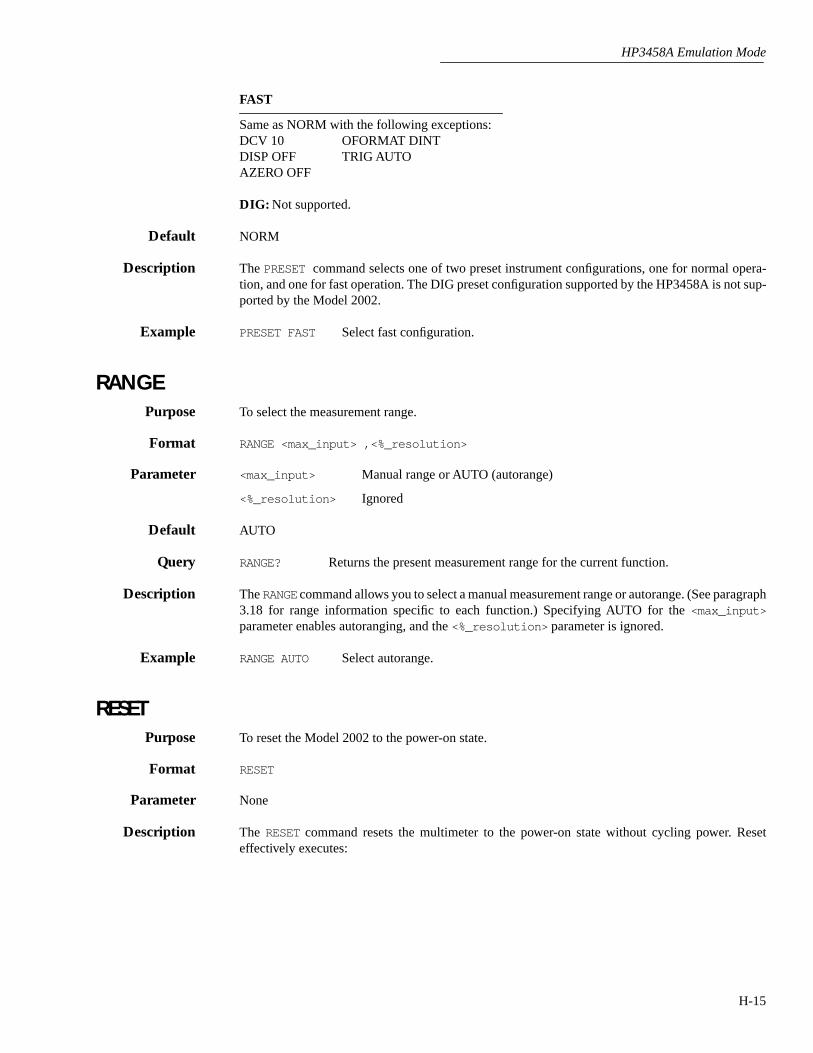
HP3458A Emulation Mode
H-15
FAST
Same as NORM with the following exceptions:DCV 10 OFORMAT DINTDISP OFF TRIG AUTOAZERO OFF
DIG: Not supported.
Default NORM
Description The PRESET command selects one of two preset instrument configurations, one for normal opera-tion, and one for fast operation. The DIG preset configuration supported by the HP3458A is not sup-ported by the Model 2002.
Example PRESET FAST Select fast configuration.
RANGEPurpose To select the measurement range.
Format RANGE <max_input> ,<%_resolution>
Parameter <max_input> Manual range or AUTO (autorange)
<%_resolution> Ignored
Default AUTO
Query RANGE? Returns the present measurement range for the current function.
Description The RANGE command allows you to select a manual measurement range or autorange. (See paragraph3.18 for range information specific to each function.) Specifying AUTO for the <max_input>parameter enables autoranging, and the <%_resolution> parameter is ignored.
Example RANGE AUTO Select autorange.
RESETPurpose To reset the Model 2002 to the power-on state.
Format RESET
Parameter None
Description The RESET command resets the multimeter to the power-on state without cycling power. Reseteffectively executes:

HP3458A Emulation Mode
H-16
AZERO ON DCV AUTODISP ON EMASK 32767 (all errors enabled)FSOURCE ACV MEM OFFMFORMAT SREAL NDIG 7NPLC 10 NRDGS 1,AUTOOCOMP OFF OFORMAT ASCIITARM AUT TIMER 1TRIG AUTO
All other commands and settings are unaffected.
REV?Purpose To request the main and front panel revision levels.
Format REV?
Response Main firmware revision/Front panel firmware revision
Description The REV? query allows you to request both the main processor firmware revision level, and the frontpanel display controller firmware revision level. The instrument returns two numbers separated by aslash: (1) the main processor firmware revision level, and (2) the front panel display controller firm-ware revision level.
The response form used by the Model 2002 is different from that of the HP3458A.
RMEM?Purpose To request readings stored in memory.
Format RMEM?
Response Reading #1, Reading #2, ... Reading #n
Description The RMEM? query returns all readings currently stored in memory. Note that the format of readingsreturned differs from that of the HP3458A. The Model 2002 returns all readings in one text block,separated by commas, with a string terminator only at the end of the block. The HP3458 includes aterminator between each reading. Also note that this command has been changed to a query-onlyformat.
RQSPurpose To enable/disable status register bits that can cause an SRQ.
Format RQS <mask>

HP3458A Emulation Mode
H-17
Parameter <mask>
Decimal weight Bit number Enabled condition
4 2 SRQ command executed8 3 Power-on SRQ32 5 Error (consult the error register)64 6 Service Requested (cannot disable this bit)128 7 Data available
Default 0
Query RQS? Returns the weighted sum of all enabled status register bits.
Description The RQS command enables one or more bits in the status register. When an enabled condition occurs,the SRQ line is asserted. All other conditions and bits are not supported, and thus are always 0. Toenable multiple bits, add up the individual bit weights.
The SRQ command must be sent to enable SRQ.
Example RQS 32 SRQ on error.RQS 160 SRQ on error and data available.
RSTATEPurpose To recall an instrument configuration from memory.
Format RSTATE <state>
Parameter <state>
Memory option Valid <state> parameters
No extended memory SAV02002-MEM1 installed SAV0-SAV42002-MEM2 installed SAV0-SAV9
Default SAV0
Description The RSTATE command recalls a stored state from memory and configures the multimeter for thatstate. These states are saved by the SSTATE command. Note that the number of valid saved statesdepends on the amount of installed memory as indicated above.
Example RSTATE SAV0 Recall state 0.
SETACV Purpose To select the RMS conversion technique used for AC and AC+DC measurements.
Format SETACV <type>
Parameter <type>
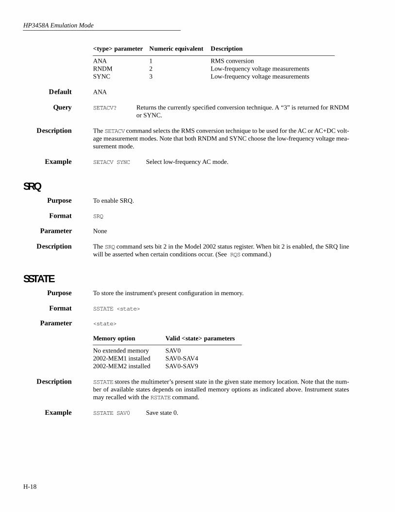
HP3458A Emulation Mode
H-18
<type> parameter Numeric equivalent Description
ANA 1 RMS conversionRNDM 2 Low-frequency voltage measurementsSYNC 3 Low-frequency voltage measurements
Default ANA
Query SETACV? Returns the currently specified conversion technique. A “3” is returned for RNDMor SYNC.
Description The SETACV command selects the RMS conversion technique to be used for the AC or AC+DC volt-age measurement modes. Note that both RNDM and SYNC choose the low-frequency voltage mea-surement mode.
Example SETACV SYNC Select low-frequency AC mode.
SRQPurpose To enable SRQ.
Format SRQ
Parameter None
Description The SRQ command sets bit 2 in the Model 2002 status register. When bit 2 is enabled, the SRQ linewill be asserted when certain conditions occur. (See RQS command.)
SSTATEPurpose To store the instrument's present configuration in memory.
Format SSTATE <state>
Parameter <state>
Memory option Valid <state> parameters
No extended memory SAV02002-MEM1 installed SAV0-SAV42002-MEM2 installed SAV0-SAV9
Description SSTATE stores the multimeter’s present state in the given state memory location. Note that the num-ber of available states depends on installed memory options as indicated above. Instrument statesmay recalled with the RSTATE command.
Example SSTATE SAV0 Save state 0.
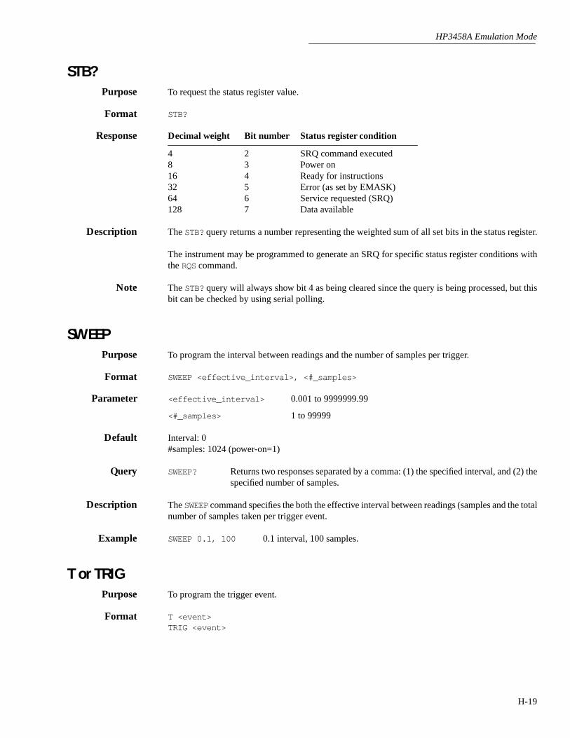
HP3458A Emulation Mode
H-19
STB?Purpose To request the status register value.
Format STB?
Response Decimal weight Bit number Status register condition
4 2 SRQ command executed8 3 Power on16 4 Ready for instructions32 5 Error (as set by EMASK)64 6 Service requested (SRQ)128 7 Data available
Description The STB? query returns a number representing the weighted sum of all set bits in the status register.
The instrument may be programmed to generate an SRQ for specific status register conditions withthe RQS command.
Note The STB? query will always show bit 4 as being cleared since the query is being processed, but thisbit can be checked by using serial polling.
SWEEPPurpose To program the interval between readings and the number of samples per trigger.
Format SWEEP <effective_interval>, <#_samples>
Parameter <effective_interval> 0.001 to 9999999.99
<#_samples> 1 to 99999
Default Interval: 0#samples: 1024 (power-on=1)
Query SWEEP? Returns two responses separated by a comma: (1) the specified interval, and (2) thespecified number of samples.
Description The SWEEP command specifies the both the effective interval between readings (samples and the totalnumber of samples taken per trigger event.
Example SWEEP 0.1, 100 0.1 interval, 100 samples.
T or TRIGPurpose To program the trigger event.
Format T <event>TRIG <event>
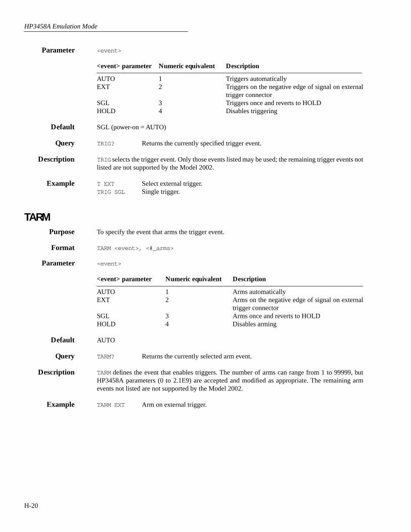
HP3458A Emulation Mode
H-20
Parameter <event>
<event> parameter Numeric equivalent Description
AUTO 1 Triggers automaticallyEXT 2 Triggers on the negative edge of signal on external
trigger connectorSGL 3 Triggers once and reverts to HOLDHOLD 4 Disables triggering
Default SGL (power-on = AUTO)
Query TRIG? Returns the currently specified trigger event.
Description TRIG selects the trigger event. Only those events listed may be used; the remaining trigger events notlisted are not supported by the Model 2002.
Example T EXT Select external trigger.TRIG SGL Single trigger.
TARMPurpose To specify the event that arms the trigger event.
Format TARM <event>, <#_arms>
Parameter <event>
<event> parameter Numeric equivalent Description
AUTO 1 Arms automaticallyEXT 2 Arms on the negative edge of signal on external
trigger connectorSGL 3 Arms once and reverts to HOLDHOLD 4 Disables arming
Default AUTO
Query TARM? Returns the currently selected arm event.
Description TARM defines the event that enables triggers. The number of arms can range from 1 to 99999, butHP3458A parameters (0 to 2.1E9) are accepted and modified as appropriate. The remaining armevents not listed are not supported by the Model 2002.
Example TARM EXT Arm on external trigger.
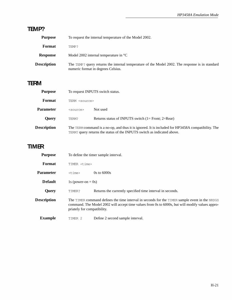
HP3458A Emulation Mode
H-21
TEMP?Purpose To request the internal temperature of the Model 2002.
Format TEMP?
Response Model 2002 internal temperature in °C
Description The TEMP? query returns the internal temperature of the Model 2002. The response is in standardnumeric format in degrees Celsius.
TERMPurpose To request INPUTS switch status.
Format TERM <source>
Parameter <source> Not used
Query TERM? Returns status of INPUTS switch (1= Front; 2=Rear)
Description The TERM command is a no-op, and thus it is ignored. It is included for HP3458A compatibility. TheTERM? query returns the status of the INPUTS switch as indicated above.
TIMER Purpose To define the timer sample interval.
Format TIMER <time>
Parameter <time> 0s to 6000s
Default 1s (power-on = 0s)
Query TIMER? Returns the currently specified time interval in seconds.
Description The TIMER command defines the time interval in seconds for the TIMER sample event in the NRDGScommand. The Model 2002 will accept time values from 0s to 6000s, but will modify values appro-priately for compatibility.
Example TIMER 2 Define 2 second sample interval.
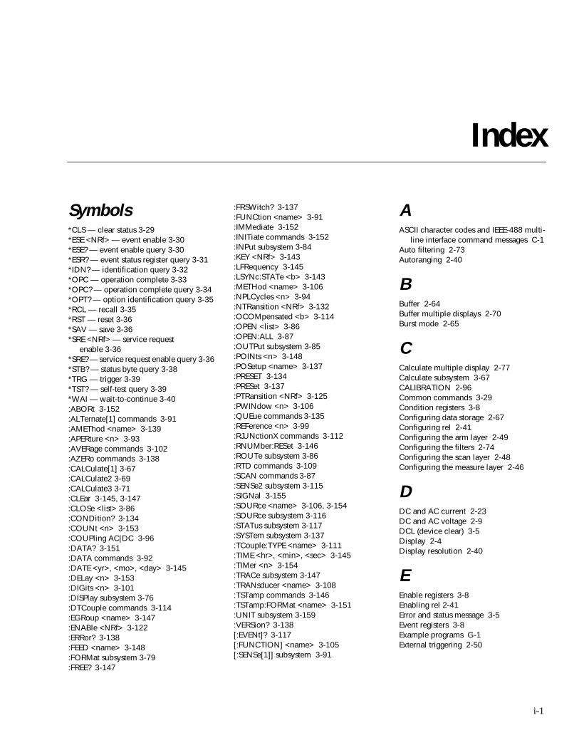
Index
Symbols
*CLS — clear status 3-29*ESE <NRf> — event enable 3-30*ESE? — event enable query 3-30*ESR? — event status register query 3-31*IDN? — identification query 3-32*OPC — operation complete 3-33*OPC? — operation complete query 3-34*OPT? — option identification query 3-35*RCL — recall 3-35*RST — reset 3-36*SAV — save 3-36*SRE <NRf> — service request
enable 3-36*SRE? — service request enable query 3-36*STB? — status byte query 3-38*TRG — trigger 3-39*TST? — self-test query 3-39*WAI — wait-to-continue 3-40:ABORt 3-152:ALTernate[1] commands 3-91:AMEThod <name> 3-139:APERture <n> 3-93:AVERage commands 3-102:AZERo commands 3-138:CALCulate[1] 3-67:CALCulate2 3-69:CALCulate3 3-71:CLEar 3-145, 3-147:CLOSe <list> 3-86:CONDition? 3-134:COUNt <n> 3-153:COUPling AC|DC 3-96:DATA? 3-151:DATA commands 3-92:DATE <yr>, <mo>, <day> 3-145:DELay <n> 3-153:DIGits <n> 3-101:DISPlay subsystem 3-76:DTCouple commands 3-114:EGRoup <name> 3-147:ENABle <NRf> 3-122:ERRor? 3-138:FEED <name> 3-148:FORMat subsystem 3-79:FREE? 3-147
:FRSWitch? 3-137:FUNCtion <name> 3-91:IMMediate 3-152:INITiate commands 3-152:INPut subsystem 3-84:KEY <NRf> 3-143:LFRequency 3-145:LSYNc:STATe <b> 3-143:METHod <name> 3-106:NPLCycles <n> 3-94:NTRansition <NRf> 3-132:OCOMpensated <b> 3-114:OPEN <list> 3-86:OPEN:ALL 3-87:OUTPut subsystem 3-85:POINts <n> 3-148:POSetup <name> 3-137:PRESET 3-134:PRESet 3-137:PTRansition <NRf> 3-125:PWINdow <n> 3-106:QUEue commands 3-135:REFerence <n> 3-99:RJUNctionX commands 3-112:RNUMber:RESet 3-146:ROUTe subsystem 3-86:RTD commands 3-109:SCAN commands 3-87:SENSe2 subsystem 3-115:SIGNal 3-155:SOURce <name> 3-106, 3-154:SOURce subsystem 3-116:STATus subsystem 3-117:SYSTem subsystem 3-137:TCouple:TYPE <name> 3-111:TIME <hr>, <min>, <sec> 3-145:TIMer <n> 3-154:TRACe subsystem 3-147:TRANsducer <name> 3-108:TSTamp commands 3-146:TSTamp:FORMat <name> 3-151:UNIT subsystem 3-159:VERSion? 3-138[:EVENt]? 3-117[:FUNCTION] <name> 3-105[:SENSe[1]] subsystem 3-91
A
ASCII character codes and IEEE-488 multi-line interface command messages C-1
Auto filtering 2-73Autoranging 2-40
B
Buffer 2-64Buffer multiple displays 2-70Burst mode 2-65
C
Calculate multiple display 2-77Calculate subsystem 3-67CALIBRATION 2-96Common commands 3-29Condition registers 3-8Configuring data storage 2-67Configuring rel 2-41Configuring the arm layer 2-49Configuring the filters 2-74Configuring the scan layer 2-48Configuring the measure layer 2-46
D
DC and AC current 2-23DC and AC voltage 2-9DCL (device clear) 3-5Display 2-4Display resolution 2-40
E
Enable registers 3-8Enabling rel 2-41Error and status message 3-5Event registers 3-8Example programs G-1External triggering 2-50
i-1
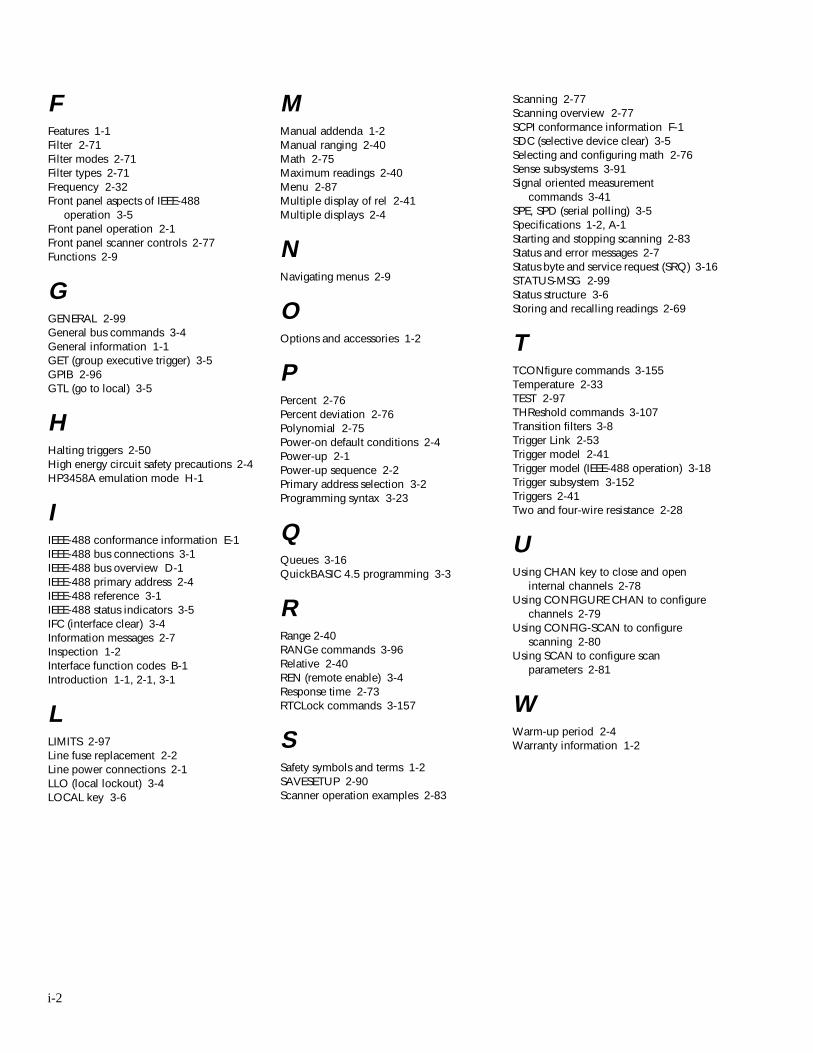
F
Features 1-1Filter 2-71Filter modes 2-71Filter types 2-71Frequency 2-32Front panel aspects of IEEE-488
operation 3-5Front panel operation 2-1Front panel scanner controls 2-77Functions 2-9
G
GENERAL 2-99General bus commands 3-4General information 1-1GET (group executive trigger) 3-5GPIB 2-96GTL (go to local) 3-5
H
Halting triggers 2-50High energy circuit safety precautions 2-4HP3458A emulation mode H-1
I
IEEE-488 conformance information E-1IEEE-488 bus connections 3-1IEEE-488 bus overview D-1IEEE-488 primary address 2-4IEEE-488 reference 3-1IEEE-488 status indicators 3-5IFC (interface clear) 3-4Information messages 2-7Inspection 1-2Interface function codes B-1Introduction 1-1, 2-1, 3-1
L
LIMITS 2-97Line fuse replacement 2-2Line power connections 2-1LLO (local lockout) 3-4LOCAL key 3-6
M
Manual addenda 1-2Manual ranging 2-40Math 2-75Maximum readings 2-40Menu 2-87Multiple display of rel 2-41Multiple displays 2-4
N
Navigating menus 2-9
O
Options and accessories 1-2
P
Percent 2-76Percent deviation 2-76Polynomial 2-75Power-on default conditions 2-4Power-up 2-1Power-up sequence 2-2Primary address selection 3-2Programming syntax 3-23
Q
Queues 3-16QuickBASIC 4.5 programming 3-3
R
Range 2-40RANGe commands 3-96Relative 2-40REN (remote enable) 3-4Response time 2-73RTCLock commands 3-157
S
Safety symbols and terms 1-2SAVESETUP 2-90Scanner operation examples 2-83
Scanning 2-77Scanning overview 2-77SCPI conformance information F-1SDC (selective device clear) 3-5Selecting and configuring math 2-76Sense subsystems 3-91Signal oriented measurement
commands 3-41SPE, SPD (serial polling) 3-5Specifications 1-2, A-1Starting and stopping scanning 2-83Status and error messages 2-7Status byte and service request (SRQ) 3-16STATUS-MSG 2-99Status structure 3-6Storing and recalling readings 2-69
T
TCONfigure commands 3-155Temperature 2-33TEST 2-97THReshold commands 3-107Transition filters 3-8Trigger Link 2-53Trigger model 2-41Trigger model (IEEE-488 operation) 3-18Trigger subsystem 3-152Triggers 2-41Two and four-wire resistance 2-28
U
Using CHAN key to close and open internal channels 2-78
Using CONFIGURE CHAN to configure channels 2-79
Using CONFIG-SCAN to configure scanning 2-80
Using SCAN to configure scan parameters 2-81
W
Warm-up period 2-4Warranty information 1-2
i-2

Service Form
Model No. Serial No. Date
Name and Telephone No.
Company
List all control settings, describe problem and check boxes that apply to problem.
Intermittent
Analog output follows display
Particular range or function bad; specify
IEEE failure
Obvious problem on power-up
Batteries and fuses are OK
Front panel operational
All ranges or functions are bad
Checked all cables
Display or output (check one)
Drifts
Unable to zero
Unstable
Will not read applied input
Overload
Calibration only
CertiÞcate of calibration required
Data required(attach any additional sheets as necessary)
Show a block diagram of your measurement system including all instruments connected (whether power is turned on or not).Also, describe signal source.
Where is the measurement being performed? (factory, controlled laboratory, out-of-doors, etc.)
What power line voltage is used? Ambient temperature? ¡F
Relative humidity? Other?
Any additional information. (If special modiÞcations have been made by the user, please describe.)
Be sure to include your name and phone number on this service form
.

Keithley Instruments, Inc.
28775 Aurora RoadCleveland, Ohio 44139
Printed in the U.S.A.