MODEL 1912XR COMMAND PROCESSOR PANEL PROGRAMMING MANUAL
42
123 2841 E. Industrial Drive Springfield, MO 65802-6310 800-641-4282 MODEL 1912XR COMMAND PROCESSOR PANEL PROGRAMMING MANUAL Do Not Throw Away! This programming manual contains information you need to program and service the 1912XR panel and should be kept along with your other DMP technical documentation. LT-0171 (10/95)
Transcript of MODEL 1912XR COMMAND PROCESSOR PANEL PROGRAMMING MANUAL

1232841 E. Industrial Drive Springfield, MO 65802-6310 800-641-4282
MODEL 1912XRCOMMAND PROCESSOR PANEL
PROGRAMMING MANUAL
Do Not Throw Away!This programming manual contains information you need to program andservice the 1912XR panel and should be kept along with your other DMPtechnical documentation.
LT-0171 (10/95)

ii
MODEL 1912XR PROGRAMMING MANUAL
Copyright © 1993 – 1995 Digital Monitoring Products, Inc.
Information furnished by DMP is believed to be accurate and reliable.This information is subject to change without notice.
When using the Series 1912XR control for any UL, NFPA, CSFM, or other listingorganization's approved methods, refer to this manual and the 1912XR Installation Guide(LT-0169). These documents outline the installation and programming requirements ofall applications for which the 1912XR is approved.

iii
TABLE OF CONTENTSSectionINTRODUCTION
Before You Begin ............................................................................................ 1.1Getting Started ................................................................................................ 1.2Programmer Operation .................................................................................... 1.3Programmer Access Codes ............................................................................. 1.4Reset Timeout ................................................................................................. 1.5Special Keys .................................................................................................... 1.6Entering Alpha Characters .............................................................................. 1.7Entering Spaces with Alpha Characters .......................................................... 1.8Keypad Prompts Display Curent Programming ............................................... 1.9
INITIALIZATIONInitialization ...................................................................................................... 2.1Clear All Codes ................................................................................................ 2.2Clear All Schedules ......................................................................................... 2.3Clear Display Events Memory ......................................................................... 2.4Clear Loop Information .................................................................................... 2.5Clear Area Information .................................................................................... 2.6Clear Communication and Remote Options .................................................... 2.7Set to Factory Defaults .................................................................................... 2.8
COMMUNICATIONCommunication ................................................................................................ 3.1Communication Type ....................................................................................... 3.2
Check-in .................................................................................................... 3.2.1Existing Wireless ....................................................................................... 3.2AExisting Printer .......................................................................................... 3.2B
2nd Phone Line ............................................................................................... 3.3Test Frequency ......................................................................................... 3.3A
Account Number .............................................................................................. 3.4Transmit Delay ................................................................................................ 3.5DTMF ............................................................................................................... 3.6Events Manager .............................................................................................. 3.7Defer Test ........................................................................................................ 3.8Test Frequency ................................................................................................ 3.9Test Time ......................................................................................................... 3.10Receiver 1 Programming ................................................................................. 3.11
Alarm Reports ........................................................................................... 3.12Supervisory and Trouble Reports ............................................................. 3.13Opening and Closing Reports by User ...................................................... 3.14Test Report ............................................................................................... 3.15Backup Reporting ...................................................................................... 3.16First Telephone Number ........................................................................... 3.17Second Telephone Number ...................................................................... 3.18
Receiver 2 Programming ................................................................................. 3.19Pager Reporting .............................................................................................. 3.20
DEVICE SETUPDevice Setup ................................................................................................... 4.1Maximum Partitions ......................................................................................... 4.2Device Definition .............................................................................................. 4.3Partition Number .............................................................................................. 4.4
REMOTE OPTIONSRemote Options ............................................................................................... 5.1Remote Key ..................................................................................................... 5.2Manufacturer Authorization ............................................................................. 5.3Armed Rings .................................................................................................... 5.4Disarmed Rings ............................................................................................... 5.5Alarm Receiver Authorization .......................................................................... 5.6
iv
TABLE OF CONTENTSSection
REMOTE OPTIONS continuedService Receiver Authorization ....................................................................... 5.7Remote Phone Number ................................................................................... 5.8Remote Disarm ................................................................................................ 5.9
SYSTEM REPORTSSystem Reports ............................................................................................... 6.1Abort Reports .................................................................................................. 6.2Bypass Reports ............................................................................................... 6.3Schedule Change Reports .............................................................................. 6.4Code Change Reports ..................................................................................... 6.5Access Keypad Reports .................................................................................. 6.6Ambush Reports .............................................................................................. 6.7
SYSTEM OPTIONSSystem Options ............................................................................................... 7.1Close Wait ....................................................................................................... 7.2Entry Delay Times ........................................................................................... 7.3Cross Zone Time ............................................................................................. 7.4Loop Retard Delay ........................................................................................... 7.5Power Fail Delay ............................................................................................. 7.6Swinger Bypass Trips ...................................................................................... 7.7Reset Swinger Bypass .................................................................................... 7.8Video/Alarm Verification .................................................................................. 7.9
OUTPUT OPTIONSOutput Options ................................................................................................ 8.1Bell Cutoff Time ............................................................................................... 8.2Automatic Bell Test .......................................................................................... 8.3Bell Action ........................................................................................................ 8.4
Fire Type ................................................................................................... 8.4ABurglary Type ............................................................................................ 8.4BSupervisory Type ...................................................................................... 8.4CPanic Type ................................................................................................ 8.4DEmergency Type ....................................................................................... 8.4EAuxiliary 1 Type ........................................................................................ 8.4FAuxiliary 2 Type ........................................................................................ 8.4G
Output Action ................................................................................................... 8.5Cutoff Output ............................................................................................. 8.5AOutput Cutoff Time .................................................................................... 8.5BCommunication Failure Output ................................................................. 8.5CFire Alarm Output ...................................................................................... 8.5DFire Trouble Output ................................................................................... 8.5EAmbush Output ......................................................................................... 8.5FEntry Output .............................................................................................. 8.5GExit Output ................................................................................................ 8.5HReady Output ............................................................................................ 8.5IPhone Trouble Output ............................................................................... 8.5JLate To Close Output ................................................................................ 8.5KDevice Fail Output ..................................................................................... 8.5L
MENU DISPLAYMenu Display ................................................................................................... 9.1Armed Status ................................................................................................... 9.2Time ................................................................................................................. 9.3Arm/Disarm ...................................................................................................... 9.4

v
TABLE OF CONTENTSSection
STATUS LISTStatus List ...................................................................................................... 10.1Display Keypads ............................................................................................ 10.2System Monitor Troubles ............................................................................... 10.3Fire Loops ...................................................................................................... 10.4Burglary Loops .............................................................................................. 10.5Supervisory Loops ......................................................................................... 10.6Panic Loops ................................................................................................... 10.7Emergency Loops .......................................................................................... 10.8Auxiliary 1 Loops ........................................................................................... 10.9Auxiliary 2 Loops ........................................................................................... 10.10
PRINTER REPORTSPrinter Reports .............................................................................................. 11.1Arm and Disarm Reports ............................................................................... 11.2Loop Reports ................................................................................................. 11.3User Command Reports ................................................................................ 11.4Door Access Reports ..................................................................................... 11.5Supervisory Reports ...................................................................................... 11.6
AREA INFORMATIONArea Information ............................................................................................ 12.1Partition Number ............................................................................................ 12.2Mode .............................................................................................................. 12.3Exit Delay ...................................................................................................... 12.4Burglary Output ............................................................................................. 12.5Opening and Closing Reports ....................................................................... 12.6Closing Check ............................................................................................... 12.7Closing Code ................................................................................................. 12.8Any Bypass .................................................................................................... 12.9Area Schedules ............................................................................................. 12.10Primary/Secondary Schedules ...................................................................... 12.11Area Number ................................................................................................. 12.12Area Name .................................................................................................... 12.13Account Number ............................................................................................ 12.14Automatic Arming .......................................................................................... 12.15Bad Loops ..................................................................................................... 12.16Automatic Disarming ..................................................................................... 12.17Armed Output Number .................................................................................. 12.18Bank Safe and Vault ...................................................................................... 12.19Common Area ............................................................................................... 12.20
LOOP INFORMATIONLoop Information ............................................................................................ 13.1Loop Number ................................................................................................. 13.2Loop Name .................................................................................................... 13.3Loop Type ...................................................................................................... 13.4
Loop Type Specifications ........................................................................ 13.4APartition Number ............................................................................................ 13.5
Area Number ........................................................................................... 13.5AArea Perimeter ........................................................................................ 13.5BArming Loop Area Assignment ............................................................... 13.5C
Next Loop ...................................................................................................... 13.6Alarm Action .................................................................................................. 13.7Disarmed Open ............................................................................................. 13.8
Report To Transmit ................................................................................. 13.8A

vi
TABLE OF CONTENTS
Section
LOOP INFORMATION continuedOutput Number ........................................................................................ 13.8BOutput Action .......................................................................................... 13.8C
Swinger Bypass ............................................................................................. 13.9Fast Response .............................................................................................. 13.10Restoral ......................................................................................................... 13.11Cross Zone .................................................................................................... 13.12Priority ........................................................................................................... 13.13Setup Loop Expanders .................................................................................. 13.14
Program Transmitter ............................................................................... 13.14AConnect Transmitter ................................................................................ 13.14BConnect Command Transmitter .............................................................. 13.14CExisting DNET ......................................................................................... 13.14DExisting Printer ........................................................................................ 13.14E
Prewarn Addresses ....................................................................................... 13.15Entry Delay .................................................................................................... 13.16Loop Retard ................................................................................................... 13.17Presignal Addresses ...................................................................................... 13.18
STOPStop ............................................................................................................... 14.1
SET ACCESS CODESet Access Code ........................................................................................... 15.1
APPENDIXEvents Manager ............................................................................................ 16.1Loop Type Descriptions ................................................................................. 16.2Diagnostics Function ..................................................................................... 16.3
New and recent additionsSec. Description Date
1.5 Revised the Reset Timeout description. 6/95
3.2 Added the Contact ID format option. 6/95
3.2A Added Existing Wireless display description. 6/95
3.2B Added Existing Printer display description. 6/95
3.3 Added Cellular prompt for 2nd phone line. 6/95
3.18 Added description of alternate dial sequence. 6/95
4.3 Added new single loop modules. 6/95
6.2 Abort report during Transmit Delay description. 6/95
7.9 Added Video/Alarm Verification description. 6/95
8.5 Revised the Output Action description. 6/95
11.1 Added Printer Reports sections (11.1 to 11.6). 6/95
12.3 Revised Home/Away description. 6/95
12.18 Revised Armed Output Number description. 6/95
13.6A Added Wireless programming instructions. 6/95
13.8A Added programming caution note. 6/95
14.1 Revised the Stop Routine function description. 6/95
16.3 Revised the Test 881 function description. 6/95
Sec. Description Date
3.2 Added the Host Communication Type. 7/95
3.2.1 Added Check-in Time for Host Communication. 7/95
3.3 Added Host option for 2nd phone line. 7/95
3.20 Added Pager Direct™ reporting option. 7/95
3.3 Added "area code" for cellular reporting 10/95

Digital Monitoring Products, Inc. 1912XR Programming
Page 1
1-INTRODUCTION
Introduction1.1 Before You Begin
About this ManualThis manual provides programming information for the DMP 1912XR Command Processor panel.After this Introduction, the remaining sections describe the functions of each programming menuitem along with the available options. The 1912XR contains all of its programming information in anon board processor and does not require an external programmer. After resetting the panel fromjumper J16, you can perform all programming tasks through any DMP alphanumeric keypadconnected to the system.
Reading the ContentsBefore starting to program, we recommend you read through the contents of this manual. Theinformation contained here allows you to quickly learn the programming options and operationalcapabilities of the 1912XR panel.
In addition to this manual, you should also read and be familiar with the following 1912XRdocuments:
• 1912XR Installation Guide (LT-0169)
• 1912XR Product Specification (LT-0170)
• 1912XR Security Command® User's Guide (LT-0172)
Programming Information SheetIncluded with each 1912XR panel are the Programming Information Sheets. These list the variouskeypad prompts and available options for programming the panel. Before starting, we recommendyou completely fill out each sheet with the programming options you intend to enter into the panel.
Having completed programming sheets available while entering data helps to prevent errors and canshorten the length of time you spend programming. Completed sheets also provide you with anaccurate account of the panel's program you can keep on file for future system service or expansion.
The remainder of this Introduction provides instructions for starting and ending a 1912XRprogramming session using the alphanumeric keypad.
1.2 Getting Started
The 1912XR Command Processor panel and all loop expansion devices must be completelyinstalled before you begin programming. Make sure the panel is properly grounded. Connect ACpower and a battery to the appropriate panel terminals.
Initializing the PanelWhen programming a 1912XR panel for the first time, or changing the program of an existing1912XR, we reccomend you use the Initialization function. See section 2. Initializing the panelclears previously programmed information from the panel's memory.
Program from any Keypad Address
All 1912XR programming is done through keypads correctly addressed and connected to thesystem. See the 1912XR Installation Guide (LT-0169) for keypad addressing and installationinformation. If you're programming a panel that does not have a keypad, you can temporarily use analphanumeric keypad set to address zero (all switches down). While programming with a keypad setto address zero, you cannot program from any other address.
Select address zero by placing all switches on the switchblock inside the keypad to the downposition.
Digital Monitoring Products, Inc. 1912XR Programming
Page 2
1-INTRODUCTION
1.2 Getting Started continued
Accessing the Programmer
To access the Programmer function of the 1912XR:
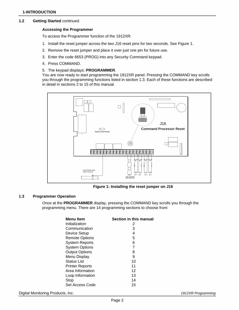
1. Install the reset jumper across the two J16 reset pins for two seconds. See Figure 1.
2. Remove the reset jumper and place it over just one pin for future use.
3. Enter the code 6653 (PROG) into any Security Command keypad.
4. Press COMMAND.
5. The keypad displays: PROGRAMMER.You are now ready to start programming the 1912XR panel. Pressing the COMMAND key scrollsyou through the programming functions listed in section 1.3. Each of these functions are describedin detail in sections 2 to 15 of this manual.
1.3 Programmer Operation
Once at the PROGRAMMER display, pressing the COMMAND key scrolls you through theprogramming menu. There are 14 programming sections to choose from:
Menu Item Section in this manualInitialization 2Communication 3Device Setup 4Remote Options 5System Reports 6System Options 7Output Options 8Menu Display 9Status List 10Printer Reports 11Area Information 12Loop Information 13Stop 14Set Access Code 15
AC BELLAC1 2 3 4 5 6 7 8 9 10 11 12 13 14 15 16 17 18 19GND RED YEL GRN BLKB + B - SMK L5+ L5- L1 L2 L3 L4GNDGND
1k Ω 3.3k Ω ResistorDMP Model 309
1k Ω 1k Ω
Battery Only Restart
J16
Command Processor Reset
1k Ω
Cold Water PipeEarth Ground
Figure 1: Installing the reset jumper on J16
J16

Digital Monitoring Products, Inc. 1912XR Programming
Page 3
1-INTRODUCTION
1.3 Programmer Operation continued
To select a section for programming, press any one of the top row SELECT keys when the name ofthat section is displayed on the keypad. The detailed instructions for each programming step arefound in sections 2 to 15 of this manual.
1.4 Programmer Access Codes
The 1912XR panel allows you to enter the programming function without a code using the steps 1 to5 listed in section 1.2. We recommend, however, that you install an Access Code that restrictsprogramming to only those persons your company authorizes. You can do this by using the SETACCESS CODE feature in the programmer.
Use this new Access Code to restrict any unauthorized programming of the panel.
Installing an Access CodeAfter entering the programming function, the keypad displays PROGRAMMER. Press theCOMMAND key to advance through the programming sections until SET ACCESS CODE isdisplayed (after STOP). Press any top row SELECT key and then enter a 1 to 5 digit programmeraccess code.
Note: There are certain codes used by the panel that cannot be used for an Access Code. Whenprogramming an Access Code, do not:
• Enter a number larger than 65,535
• Use 6653 (PROG), 2313 (DIAG), or any 3-digit code starting with 98 (such as 984).
These codes must be left available for the panel's use.
Press COMMAND. The displays shows ENTER AGAIN . Enter the new access code again andpress COMMAND. The display shows CODE CHANGED. The new code number must now beentered before the programmer function can be accessed.
This code number should be kept in a secure place with access limited to only those personsauthorized by your company to program the panel.
Lost Access Code requires factory reset: If you lose or forget the Access Code, the panel mustbe sent back to the factory to be reset. There is no field option for gaining access to the panelwithout a valid access code.
1.5 Reset Timeout
The 1912XR has a feature that requires you to enter the Programmer within 30 minutes of resettingthe panel. After 30 minutes, if you attempt to program by entering the 6653 (PROG) code, thekeypad displays: RESET PANEL . You must reset the panel and enter the program code within thenext 30 minutes.
If you are already in the Programmer and do not press any keys on the programming keypad for 30minutes, the panel terminates programming. As an additional safeguard, all data entered up to thattime is saved in the panel's memory.

Digital Monitoring Products, Inc. 1912XR Programming
Page 4
1-INTRODUCTION
1.6 Special Keys
COMMAND KeyThe COMMAND key is used to step ahead in programming. Pressing the COMMAND key allowsyou to go forward through the programming menu and through each step of a programming section.As you go through the programming, the keypad display shows any current programming alreadystored in the panel's memory.
If the information is not to be changed, press the COMMAND key to advance to the next step.
The COMMAND key is also used to enter information into the panel's memory such as phonenumbers or loop names. Press the COMMAND key after you've entered the information and it'sbeing displayed correctly on the keypad.
ARROW KeyUse the ARROW key to back up one step while in the programming menu or within a programmingsection. The ARROW key is also used when an error is made while entering information. Press theARROW key once to erase the last character entered.
SELECT KeysThe top row of keys are called the SELECT keys. Each time a SELECT key is to be used, thekeypad displays the function or options above the key. Displaying choices above the individualSELECT keys allows them to be used for many different applications. For example, you can enterAM or PM when programming the automatic test time or answer YES or NO for a system option.
During programming, the SELECT keys also allow you to change information currently in the panel'smemory. As you step through each program option, the keypad displays the current information. Tochange this information, press the appropriate SELECT key under the display then enter the newinformation through the keypad.
If you are changing a phone number or account number, press the appropriate digit keys. If enteringa communication type or choosing a programming option, the keypad displays the availableresponse options above the SELECT keys. When there are more than four response optionsavailable, the keypad displays the first four. Pressing the COMMAND key brings up the next 1 to 4options on the display. Pressing the ARROW key allows you to review the previous four choices.
The SELECT keys are also used for selecting a section from the programming menu. This is doneby pressing any one of the SELECT keys when the name of the programming section you want isdisplayed.
1 2 3 4
5 6 7 8
9 0 COMMAND
A B C DEF GHI JKL
VWXSTUPQRMNO
YZ
POWER
Figure 2: Keypad Function keys
COMMAND KeyARROW Key
SELECT Keys

Digital Monitoring Products, Inc. 1912XR Programming
Page 5
1-INTRODUCTION
Figure 3: Keypad display and top row keys
Center CharacterLeft Character Right Character
S Y S T E M O N
BELL TST YES
Press the top row select key.
BELL TST NO
The keypad display changes to the newlyselected option. Press COMMAND.
NEXT
Figure 4: Changing the current option selected.
1.7 Entering Alpha Characters
Some options during programming require you to enter alpha characters. To enter an alphacharacter, press the key that has that letter written below it. The keypad displays the number digit ofthe key. Next, press the SELECT key that corresponds to the location of the letter under the key.Pressing a different SELECT key changes the letter. When another digit key is pressed, the lastletter displayed is retained and the process is started over.
1.8 Entering Spaces With Alpha Characters
To enter a space in an alpha entry, press the 9 digit key followed by the third SELECT key. Thethree characters on the 9 digit key are Y, Z, and space.
1.9 Keypad Prompts Display Current Programming
Each programming prompt displayed at the keypad shows the currently selected option in thepanel's memory. These options are either shown as a number, a blank, or a NO or YES. To changea number or blank to a new number, press any top row SELECT key. The current option is replacedwith a dash. Press the number(s) on the keypad you want to enter as the new number for thatprompt.
It is not necessary to enter numbers with leading or trailing zeros. The 1912XR automatically rightjustifies the number when you press the COMMAND key.
To change a programming prompt that requires a NO or YES response, press the top row SELECTkey under the response not selected.
For example, if the current prompt is selected as YES and you want to change it to NO, press thethird top row SELECT key. The display changes to NO. Press the COMMAND key to go to the nextprompt. See Figure 4.

Digital Monitoring Products, Inc. 1912XR Programming
Page 6
2-INITIALIZATION
2.1 This function allows you to clear selected parts of the panel's memory back to thefactory defaults in preparation for system programming.
After you select YES to clear a section of memory the panel asks if you are sureyou want to clear the memory. This is a safeguard against accidently erasing partof your programming. No memory is cleared from the programming until youanswer yes to the SURE? YES NO question.
A description of each selection follows:
2.2 CLEAR ALL CODES - YES clears the user code memory and assigns theuser code number 99 to the highest user position in each area.
2.3 CLEAR ALL SCHEDULES - YES clears all primary, secondary, permanent,temporary, and output schedules.
2.4 CLEAR DISPLAY EVENTS MEMORY - YES clears the Security Commandkeypad display events memory.
2.5 CLEAR LOOP INFORMATION - YES clears the loop information for all loops. Allloops are marked * UNUSED * and must be renamed before being able todisplay on any system keypad.
2.6 CLEAR AREA INFORMATION - YES clears the area information for all areas. Allareas are marked * UNUSED * and must be renamed before being able todisplay on any system keypad.
2.7 CLEAR COMMUNICATION AND REMOTE OPTIONS - YES clears thecommunication and remote options programming to factory defaults.
2.8 SET TO FACTORY DEFAULTS - YES sets the panel's programming back to thefactory default selections. Selecting Factory Defaults does not clear the panel'sEvent Memory or user codes.
INITIALIZATION
CODES? NO YES
SURE? YES NO
SCHEDS? NO YES
SURE? YES NO
EVENTS? NO YES
SURE? YES NO
LOOPS? NO YES
SURE? YES NO
AREAS? NO YES
SURE? YES NO
COM/RMT? NO YES
SURE? YES NO
DEFAULTS NO YES
SURE? YES NO

Digital Monitoring Products, Inc. 1912XR Programming
Page 7
3.1 This section allows you to configure the communication options for the 1912XRpanel. The information you'll program varies with the Communication Type.
3.2 COMMUNICATION TYPE - Specifies the communication method the panel usesto contact the SCS-1 Receiver. Press any SELECT key to display the followingcommunication options:
NONE - For local systems. Selecting this ends communication programming.
DD - Dialer connection to a DMP SCS-1 Receiver.
MPX - Multiplex connection to a DMP SCS-1 Receiver.
DDMX - Dialer connection during disarmed periods with multiplex connectionestablished after the last area in the system arms. After selecting DDMX, thedisplay changes to DDMX PHONE NO., press COMMAND to enter the multiplexphone number.
DNET - Data network connection to a DMP SCS-1 Receiver following multiplexrules. This option requires the use of the 862 Network Interface Card. You canalso use the backup dialer capability of the 1912XR by selecting the option 2NDLINE as YES. See section 3.3.
You cannot select DNET if you are using the 872 H ARD-WIRE-LESS™ or 862P PrinterInterface Cards: If you attempt to program DNET while using either card, the keypaddisplays an error message. See sections 3.2A and 3.2B.
CID - This option allows the panel to communicate to non-DMP receivers usingthe Ademco Contact ID format. When selected, the panel sends all of its alarm,trouble, and supervisory reports to the Contact ID receiver programmed inReceiver 1 and 2 Programming.
HST (Host) - Asynchronous communication using the 862N Network InterfaceCard. The DMP Host/Output reporting format is transmitted over anasynchronous computer or radio network to the SCS-1 Receiver. All loop alarmsand restorals transmitted on the Host Channel are also duplicated on the 2NDLINE (section 3.3) if it's selected.
If the Host channel fails to receive a proper acknowledgment after five attempts,the panel sends a WARNING: NETWORK TROUBLE (S72) report on the 2NDLINE. The next time a report is sent by the panel over the Host channel, thepanel sends a NETWORK RESTORED (S73) report over the 2ND LINE.
3.2.1 CHECK-IN TIME - Enter two digits (00 to 60) to specify the time delay in minutesthe panel uses to send the next Check-in report. This prompt is only displayed ifHST is selected in section 3.2. Since HST is not a polled communication method,the Check-in time allows the SCS-1 Receiver to get a Check-in report (s070)periodically to verify continuous communication with the panel. SCS-1/805firmware is required in the SCS-1 Receiver. Entering zero causes the Check-inreport to not be sent. Press COMMAND to continue.
Selecting AA instead of entering a Check-in time causes the panel to send theCheck-in report at random times. When all areas are disarmed, the report is sentrandomly but always within 60 minutes. If any area is armed, the report is sentevery six minutes. The SCS-1 Receiver verifies that the next Check-in report isreceived at the appropriate time. SCS-1/805 firmware is required in the SCS-1Receiver.
3.2A EXISTING WIRELESS - Wireless loops have been programmed for one or moreof the addresses 100 to 199. This display is followed by the loop number andloop name for each wireless loop. You must remove the wireless loopprogramming to use the DNET option for interfacing with a data network.
COMM TYPE: NONE
3-COMMUNICATION
COMMUNICATION
NONE DD MPX DDMX
DNET C I D HST
EXISTING WIRLESS
CHECKIN:
CHECKIN: – AA
Digital Monitoring Products, Inc. 1912XR Programming
Page 8
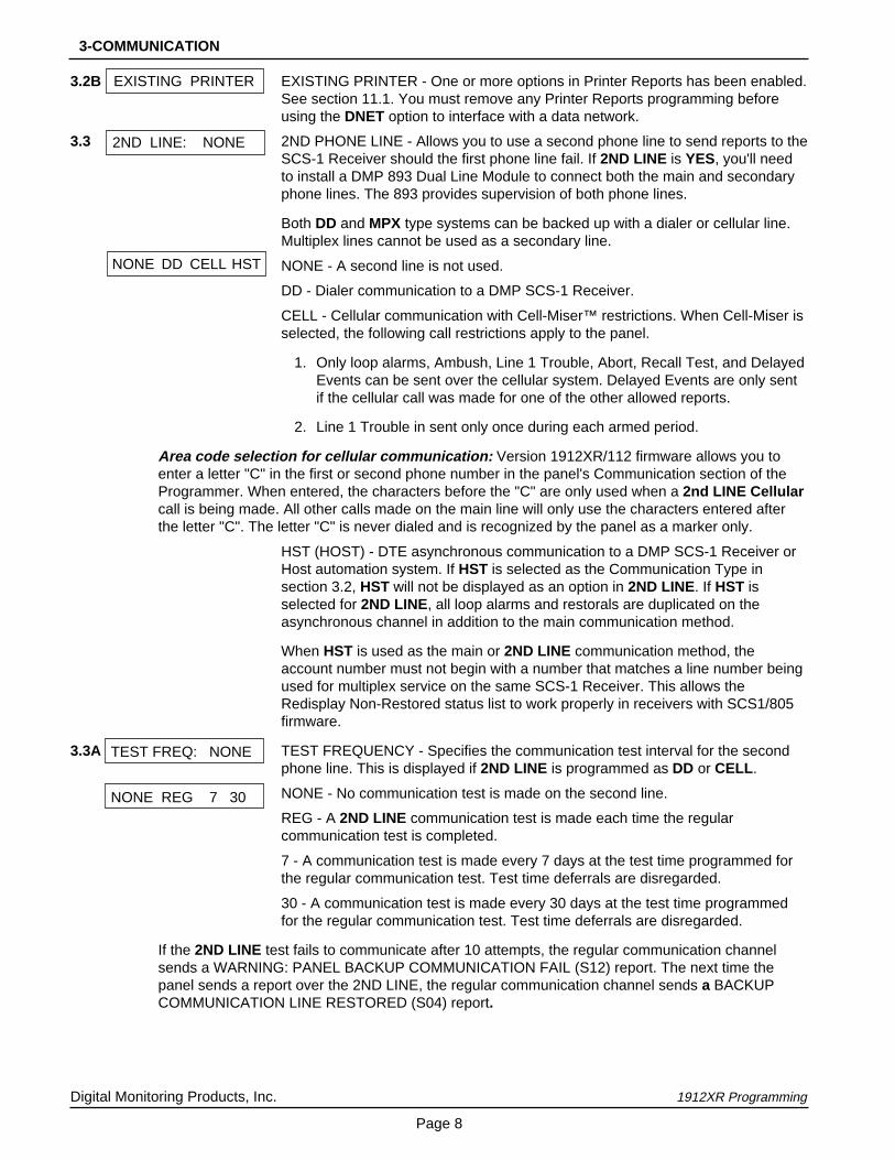
3.2B EXISTING PRINTER - One or more options in Printer Reports has been enabled.See section 11.1. You must remove any Printer Reports programming beforeusing the DNET option to interface with a data network.
3.3 2ND PHONE LINE - Allows you to use a second phone line to send reports to theSCS-1 Receiver should the first phone line fail. If 2ND LINE is YES, you'll needto install a DMP 893 Dual Line Module to connect both the main and secondaryphone lines. The 893 provides supervision of both phone lines.
Both DD and MPX type systems can be backed up with a dialer or cellular line.Multiplex lines cannot be used as a secondary line.
NONE - A second line is not used.
DD - Dialer communication to a DMP SCS-1 Receiver.
CELL - Cellular communication with Cell-Miser™ restrictions. When Cell-Miser isselected, the following call restrictions apply to the panel.
1. Only loop alarms, Ambush, Line 1 Trouble, Abort, Recall Test, and DelayedEvents can be sent over the cellular system. Delayed Events are only sentif the cellular call was made for one of the other allowed reports.
2. Line 1 Trouble in sent only once during each armed period.
Area code selection for cellular communication: Version 1912XR/112 firmware allows you toenter a letter "C" in the first or second phone number in the panel's Communication section of theProgrammer. When entered, the characters before the "C" are only used when a 2nd LINE Cellularcall is being made. All other calls made on the main line will only use the characters entered afterthe letter "C". The letter "C" is never dialed and is recognized by the panel as a marker only.
HST (HOST) - DTE asynchronous communication to a DMP SCS-1 Receiver orHost automation system. If HST is selected as the Communication Type insection 3.2, HST will not be displayed as an option in 2ND LINE. If HST isselected for 2ND LINE, all loop alarms and restorals are duplicated on theasynchronous channel in addition to the main communication method.
When HST is used as the main or 2ND LINE communication method, theaccount number must not begin with a number that matches a line number beingused for multiplex service on the same SCS-1 Receiver. This allows theRedisplay Non-Restored status list to work properly in receivers with SCS1/805firmware.
3.3A TEST FREQUENCY - Specifies the communication test interval for the secondphone line. This is displayed if 2ND LINE is programmed as DD or CELL .
NONE - No communication test is made on the second line.
REG - A 2ND LINE communication test is made each time the regularcommunication test is completed.
7 - A communication test is made every 7 days at the test time programmed forthe regular communication test. Test time deferrals are disregarded.
30 - A communication test is made every 30 days at the test time programmedfor the regular communication test. Test time deferrals are disregarded.
If the 2ND LINE test fails to communicate after 10 attempts, the regular communication channelsends a WARNING: PANEL BACKUP COMMUNICATION FAIL (S12) report. The next time thepanel sends a report over the 2ND LINE, the regular communication channel sends a BACKUPCOMMUNICATION LINE RESTORED (S04) report.
3-COMMUNICATION
NONE DD CELL HST
2ND LINE: NONE
NONE REG 7 30
TEST FREQ: NONE
EXISTING PRINTER

Digital Monitoring Products, Inc. 1912XR Programming
Page 9
3.4 ACCOUNT NUMBER - Enter the account number sent to the SCS-1 Receiver.
DD, CID, and HST - The range of valid account numbers for a panel usingthese Communication Types is 1 to 65,535. For account numbers of fourdigits or less, it is not necessary to enter leading zeros. The panelautomatically right justifies the account number.
MPX, DDMX, and DNET - A 5-digit account number is required for panelsusing either of these formats. The first digit is the receiver line number. Thesecond digit is always zero. The last three digits are the panel's accountnumber. This number must be between the range of 000 and 127.
If 2ND LINE (3.3) is NO, COMMUNICATION programming ends after theaccount number is entered.
3.5 TRANSMIT DELAY- Enter the length of time the panel waits before sendingburglary reports to the SCS-1 Receiver. The available range is 1 to 60 seconds.Alarm bells and relay outputs are not delayed during this period. BurglaryOutputs in section 8 must be programmed for pulsed or steady. Set AbortReports in section 6 to YES if Opening and Closing reports are not being sent.
Enter zero to disable Transmit Delay.
3.6 DTMF - YES enables tone dialing. NO enables rotary dialing.
3.7 EVENTS MANAGER - Specifies when non-alarm reports are sent to the receiver.This selection does not affect loop alarm, loop trouble, loop restoral, supervisory,or serviceman messages. Closing reports are not delayed if you've programmeda YES for the Closing Wait option. See Section 7.2.
SND - If send is selected, all reports are sent to the receiver as they occur.
DLY - All non-alarm reports are held until the panel's memory buffer contains66 events, or until the panel's next communication with the receiver.
KEEP - All non-alarm reports are held in the panel's memory buffer untilthey're over written by new activity. You can view the contents of the memorybuffer using the DMP Remote Access™ software or the display eventsfeature in the User Menu.
Refer to the Appendix for a table listing the delayed report types.
3.8 DEFER TEST TIME - Select YES to allow the programmed test report to bedeferred if the panel communicates with the SCS-1 Receiver within the time setin Test Frequency. See section 3.9. Select NO to send the test report asprogrammed regardless of previous panel communication.
3.9 TEST FREQUENCY - Allows you to set how often the panel's test report is sentto the SCS-1 receiver. Enter from 1 to 60 days. This prompt is not displayed ifDefer Test Time is set to NO.
3.10 Press COMMAND to show the enter test time display.
Enter the time of day the panel sends the test report to the SCS-1 Receiver. Useonly entries of 00:01 to 12:00 and then choose AM or PM.
When Defer Test Time is set to NO, this option allows you to program the day ofthe week the test report is sent. Choose one day of the week or all days.
3.11 Allows you to set the options for the first receiver the 1912XR panel attempts tocontact when sending reports. The panel supports two receivers.
3.12 ALARM REPORTS - YES sends alarm and alarm restoral reports to this receiver.
3-COMMUNICATION
EVENT MGR: SEND
DTMF YES
SND DLY KEEP
DFR TEST NO
TEST FREQ: 0
TEST TIME
0 : 0 0 A M PM
RECEIVER 1 PRGMG
TEST DAY: ALL
ACCT NO: 1 2 3 4 5
XMIT DELAY: 0
ALARM YES

Digital Monitoring Products, Inc. 1912XR Programming
Page 10
3.13 SUPERVISORY/TROUBLE REPORTS - YES enables supervisory, trouble, andtrouble restoral reports, and serviceman messages to be sent to this receiver.
3.14 OPENING/CLOSING AND USER REPORTS - Enter YES to enable opening/closing, door access, schedule and code changes, bypass, and sensor resetreports by user to be sent to this receiver.
3.15 TEST REPORT - Enter YES to enable the system test report to be sent to thisreceiver. Reports are sent according to the programming in sections 3.9 to 3.10.
3.16 BACKUP REPORTING - Enter YES to enable this receiver to be a backup to theother receiver in the event the other receiver cannot be contacted.
3.17 FIRST TELEPHONE NUMBER - This is the first number the panel dials whensending reports to this receiver. Phone numbers can be up to 15 characters inlength. You can program a three second pause in the dialing sequence byentering the letter P. You can program a dial tone detect by entering the letter D.These characters are counted as part of the 15 allowable characters.
3.18 SECOND TELEPHONE NUMBER - The panel dials the second number whentwo successive tries using the first number have failed. If the panel cannot reachthe receiver after two attempts using the second number, it returns to the firstnumber and makes two additional attempts. A total of ten dialing attempts aremade using the first and second phone numbers.
Should all ten attempts fail, the panel clears the communication buffer and thenmakes one communication attempt each hour to send a TRANSMIT FAILED(S87) report to the central station receiver. The report information that was notsent to the receiver is available from the Display Events feature of the User Menuand can be downloaded with the Remote Access™ software from DMP.
Each number can be up to 15 characters in length including any P or Dcharacters entered for pause and dial tone detect. Important: Do not programany letters other than P or D.
3.19 Repeat steps 3.12 through 3.18 when using a second receiver. Defaults forReceiver 2 are factory set as NO.
If you select YES for any of the second receiver options, you must have at leastone phone number programmed in Receiver 2 programming.
3.20 PAGER REPORTING - YES allows the panel to send Alarm, Trouble, Opening,Closing, and Late to Close reports to a numeric pager. The panel uses DTMFtones to generate the account and report information sent over the pager terminalequipment. Selecting NO allows you to use the Receiver 2 Programming to sendpanel reports to a second SCS-1 Receiver.
3.20A FIRST TELEPHONE NUMBER - Enter the phone number the panel will dial tosend reports to the numeric pager. Phone numbers can be 15 characters inlength. You can program a three second pause in the dialing sequence byentering the letter P. You can program a dial tone detect by entering the letter D.These characters are counted as part of the 15 allowable characters.
3.20B PAGER IDENTIFICATION NUMBER - Enter a pager identification number if yourpager uses one. If it does, the panel waits for nine seconds after having dialed theFirst Phone Number before sending the Pager ID. After the Pager ID has beentransmitted, the panel waits another three seconds before sending the actualpager message containing the panel reports.
3-COMMUNICATION
SPV/TRBL YES
SECOND PHONE NO.
–
O/C USER YES
BACKUP NO
FIRST PHONE NO.
–
TEST RPT YES
RECEIVER 2 PRGMG
FIRST PHONE NO.
PAGER ID NUMBER
PAGER? NO YES

Digital Monitoring Products, Inc. 1912XR Programming
Page 11
4.1 This section allows you to define the physical configuration of the 1912XR panel.Enter the number of partitions in the system and the types of devices installed ateach address along with their assigned partition. You can install and address upto eight devices on the keypad data bus.
A description of each option follows:
4.2 Maximum number of partitions you want in this system. You can choose from 1 to4. To change the number displayed, press any SELECT key, enter the number ofpartitions you want to enable, and press COMMAND.
Changing the number of partitions resets user codes: Whenever you change the number ofpartitions on the 1912XR, all programmed user codes are cleared. The only code available after apartition change is the factory default of 99.
4.3 Description of the device set to this address. Leave the default STNDRD for 670,770, and 771 Security Command keypads and for all expander modules.
If the device description does not match the device installed for this address,press any SELECT key and choose the correct one from those displayed.
STANDARD - The device is either a 670, 770, or 771 keypad, a 711, 714, or 715Loop Expander, a 6155LX PIR, or a 5845LX Glassbreak.
NONE - No device is set for this address.
Press the SELECT key under the correct device description to change the currentselection. If you entered 2, 3, or 4 in section 4.2 MAX PARTITION , the keypaddisplays the following prompt. If there is only one partition programmed in section4.2, the keypad does not display the partition assignment prompt.
4.4 Enter the partition number where the current device being programmed isassigned. For systems with only one partition, leave this entry at one. Forsystems with more than one partition, press any top row SELECT key then entera 2, 3, or 4. Press COMMAND to program the next device.
Figure 5: Areas and user codes available with partitioning
PartitionsEnabled Areas Available User Code Numbers
Partition 1 1 to 8 1 to 99
Partitions 1 & 2 Partition 1 - 1 to 8
Partition 2 - 1 to 4
Partition 1 - up to 50
Partition 2 - up to 50
Partitions 1 to 3 Partition 1 - 1 to 8
Partition 2 - 1 to 4
Partition 3 - 1 to 4
Partition 1 - up to 25
Partition 2 - up to 25
Partition 3 - up to 25
Partitions 1 to 4 Partition 1 - 1 to 8
Partition 2 - 1 to 4
Partition 3 - 1 to 4
Partition 4 - 1 to 4
Partition 1 - up to 25
Partition 2 - up to 25
Partition 3 - up to 25
Partition 4 - up to 25
MAX PARTITION: 1
DEVICE 1: STNDRD
STD NONE
PARTITION NO: 1
DEVICE SETUP
4-DEVICE SETUP

Digital Monitoring Products, Inc. 1912XR Programming
Page 12
5.1 This section allows you to enter the information needed for Remote Command/Remote Programming operation.
A description of the Remote Options follow:
5.2 REMOTE KEY - This option allows you to enter a code of up to eight digits foruse in verifying the authority of an alarm or service receiver to perform a remotecommand/programming session. The receiver must give the correct key to thepanel before being allowed any remote functions. All panels are shipped from thefactory with the key preset as blank.
To enter a remote key or change the current one, press a top row SELECT keyand enter any combination of up to eight digits. Press COMMAND. The currentkey is never displayed.
5.3 MANUFACTURER AUTHORIZATION - Enter YES to allow DMP servicetechnicians to access the panel when required during system service ortroubleshooting. This authorization automatically expires within one hour.
DMP remote service is provided on a read only basis: DMP technicians can look at the systemprogramming and make suggestions only. Alterations can only be accomplished by the installingcompany's service personnel.
5.4 ARMED RINGS - Enter the number of rings the panel counts before answeringthe phone line when all areas of the system are armed. Any number from 1 to 15can be entered. If zero is entered, the panel does not answer the phone when allareas of the system are armed.
5.5 DISARMED RINGS - Enter the number of rings the panel counts beforeanswering the phone line while any areas of the system are disarmed. Anynumber from 1 to 15 can be entered. If zero is entered, the panel does notanswer the phone when any area of the system is disarmed.
5.6 ALARM RECEIVER AUTHORIZATION - Enter YES to enable remotecommands and programming to be accepted from the alarm SCS-1 Receiver.The Remote Key option can also be required.
With YES selected, the panel requests the receiver key during its firstcommunication with the first SCS-1 receiver. The panel retains this alarmreceiver key in memory and allows remote commands to be accepted from thealarm receiver. If an alarm occurs during a remote connect, the alarm report isimmediately sent to this receiver only.
When NO is selected, remote commands and programming are not acceptedfrom the alarm SCS-1 Receiver.
ALR RCVR NO
RMT KEY:
DISARM RINGS: 0
MFG AUTH NO
5-REMOTE OPTIONS
ARM RINGS: 0
REMOTE OPTIONS

Digital Monitoring Products, Inc. 1912XR Programming
Page 13
5.7 SERVICE RECEIVER AUTHORIZATION - YES enables remote commands andprogramming to be accepted from a secondary service receiver other than thealarm SCS-1 Receiver. The Remote Key option can also be required.
With YES selected, the panel requests the service receiver key the first time it'scontacted by the service receiver. The panel retains this service receiver key inmemory and accepts remote commands from the service receiver.
If an alarm occurs during a remote connect, the panel disconnects from theservice receiver and calls the alarm receiver. Alarm reports are only sent to thealarm receiver. It is important that the alarm receiver key and the servicereceiver key programmed at the central station are NOT the same so the panelcan determine the difference between receivers.
When NO is selected remote commands and programming are not acceptedfrom a secondary service receiver.
5.8 REMOTE PHONE NUMBER - Press COMMAND to enter the phone number thepanel dials whenever remote programming is requested. After entering a phonenumber, the panel allows remote commands and programming only after it hasfirst been called by the authorized receiver, disconnected itself, and has redialedthe remote phone number.
Note: If a Remote Phone Number is entered, and the function 984 + COMMANDis entered at the keypad, a remote options menu appears. This menu containsthe following options:
NUMBER - The panel allows you to enter into the keypad a phone number youwant the panel to dial. Use must use any required prefixes and area codes.
REMOTE - The panel dials the phone number programmed in Remote PhoneNumber. See section 5.8.
PICKUP - The panel picks up the phone line as Remote Access is dialing in. Thephone must be ringing before selecting PICKUP.
If a Remote Phone Number is NOT entered, the panel allows remote commandsand programming without disconnecting and redialing. The phone number can beup to 15 digits in length. Enter a D for dial tone detect and a P for a 3 secondpause.
Important: Do not program any letters other than P or D.
5.9 REMOTE DISARM - Enter YES to enable the panel to be disarmed remotely.Selecting NO disables remote disarming.
REMOTE PHONE NO.
SVC RCVR YES
–
DISARM NO
NBR RMT PICKUP
5-REMOTE OPTIONS

Digital Monitoring Products, Inc. 1912XR Programming
Page 14
6.1 This function allows you to select the reports the 1912XR sends to the SCS-1Receiver.
6.2 ABORT REPORT - YES allows the panel to send an alarm abort report to thereceiver any time an alarm report has also been sent and the bell is stillsounding. The area must be disarmed and no alarmed loops can still be armed.
Abort reports are also sent when the system is disarmed during Transmit Delayand the Bell Output is active. See section 3.5.
6.3 BYPASS REPORTS - YES allows the panel to send all loop bypasses, resets,and force arm reports to the receiver. The bypass report includes the loopnumber, loop name, and the user number of the individual operating the system.
6.4 SCHEDULE CHANGE REPORTS - YES allows the panel to send all permanentand temporary, primary and secondary, schedule changes to the receiver. Thereport includes the day, opening time, closing time, and the user number of theindividual making the change.
6.5 CODE CHANGE REPORTS - YES allows the panel to send all code additions,changes, and deletions to the receiver. The code change report includes the usernumber added or deleted and the user number of the individual making thechange.
6.6 ACCESS KEYPADS - Enter the Security Command keypad addresses that senddoor access reports to the receiver. A report is sent with each door access madefrom the selected keypads. Keypads at addresses not selected still operate thedoor strike relay but do not send door access reports. The report includes theuser number and the keypad address used.
6.7 AMBUSH - YES allows an ambush report to be sent anytime user code numberone is entered at a Security Command keypad. Selecting NO disables theambush report and allows user code number one to operate the same as allother codes.
There is one Ambush code available for each active partition programmed intothe panel.
ABORT NO
SYSTEM REPORTS
CODE CHG YES
BYPASS YES
SCHD CHG YES
AMBUSH NO
ACS KEY: - - - - - - - -
6 -SYSTEM REPORTS
Digital Monitoring Products, Inc. 1912XR Programming
Page 15
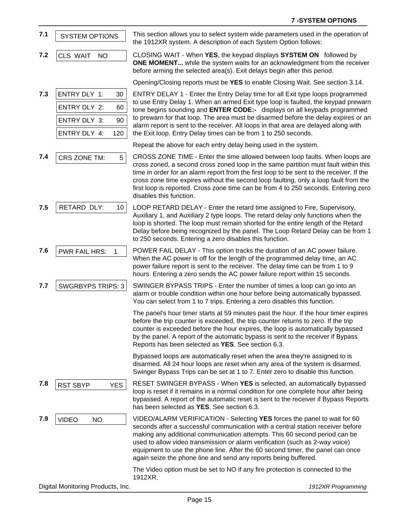
7.1 This section allows you to select system wide parameters used in the operation ofthe 1912XR system. A description of each System Option follows:
7.2 CLOSING WAIT - When YES, the keypad displays SYSTEM ON followed byONE MOMENT... while the system waits for an acknowledgment from the receiverbefore arming the selected area(s). Exit delays begin after this period.
Opening/Closing reports must be YES to enable Closing Wait. See section 3.14.
7.3 ENTRY DELAY 1 - Enter the Entry Delay time for all Exit type loops programmedto use Entry Delay 1. When an armed Exit type loop is faulted, the keypad prewarntone begins sounding and ENTER CODE:- displays on all keypads programmedto prewarn for that loop. The area must be disarmed before the delay expires or analarm report is sent to the receiver. All loops in that area are delayed along withthe Exit loop. Entry Delay times can be from 1 to 250 seconds.
Repeat the above for each entry delay being used in the system.
7.4 CROSS ZONE TIME - Enter the time allowed between loop faults. When loops arecross zoned, a second cross zoned loop in the same partition must fault within thistime in order for an alarm report from the first loop to be sent to the receiver. If thecross zone time expires without the second loop faulting, only a loop fault from thefirst loop is reported. Cross zone time can be from 4 to 250 seconds. Entering zerodisables this function.
7.5 LOOP RETARD DELAY - Enter the retard time assigned to Fire, Supervisory,Auxiliary 1, and Auxiliary 2 type loops. The retard delay only functions when theloop is shorted. The loop must remain shorted for the entire length of the RetardDelay before being recognized by the panel. The Loop Retard Delay can be from 1to 250 seconds. Entering a zero disables this function.
7.6 POWER FAIL DELAY - This option tracks the duration of an AC power failure.When the AC power is off for the length of the programmed delay time, an ACpower failure report is sent to the receiver. The delay time can be from 1 to 9hours. Entering a zero sends the AC power failure report within 15 seconds.
7.7 SWINGER BYPASS TRIPS - Enter the number of times a loop can go into analarm or trouble condition within one hour before being automatically bypassed.You can select from 1 to 7 trips. Entering a zero disables this function.
The panel's hour timer starts at 59 minutes past the hour. If the hour timer expiresbefore the trip counter is exceeded, the trip counter returns to zero. If the tripcounter is exceeded before the hour expires, the loop is automatically bypassedby the panel. A report of the automatic bypass is sent to the receiver if BypassReports has been selected as YES. See section 6.3.
Bypassed loops are automatically reset when the area they're assigned to isdisarmed. All 24 hour loops are reset when any area of the system is disarmed.Swinger Bypass Trips can be set at 1 to 7. Enter zero to disable this function.
7.8 RESET SWINGER BYPASS - When YES is selected, an automatically bypassedloop is reset if it remains in a normal condition for one complete hour after beingbypassed. A report of the automatic reset is sent to the receiver if Bypass Reportshas been selected as YES. See section 6.3.
7.9 VIDEO/ALARM VERIFICATION - Selecting YES forces the panel to wait for 60seconds after a successful communication with a central station receiver beforemaking any additional communication attempts. This 60 second period can beused to allow video transmission or alarm verification (such as 2-way voice)equipment to use the phone line. After the 60 second timer, the panel can onceagain seize the phone line and send any reports being buffered.
The Video option must be set to NO if any fire protection is connected to the1912XR.
CLS WAIT NO
SYSTEM OPTIONS
7 -SYSTEM OPTIONS
PWR FAIL HRS: 1
SWGRBYPS TRIPS: 3
RST SBYP YES
VIDEO NO
RETARD DLY: 10
ENTRY DLY 1: 30
ENTRY DLY 2: 60
ENTRY DLY 4: 120
ENTRY DLY 3: 90
CRS ZONE TM: 5

Digital Monitoring Products, Inc. 1912XR Programming
Page 16
OUTPUT OPTIONS
BELL CUTOFF: 15
BELL TST NO
BELL ACTION . . . . .
SUPRVSRY TYPE: N
BURGLARY TYPE: S
PANIC TYPE: N
8.1 OUTPUT OPTIONS - This function allows you to program the panel's Bell Outputfunctions and certain Relay Output options. Dry contact relays and voltageoutputs are available using the output harness on the 1912XR board. Refer tothe 1912XR Installation Guide (LT-0169) for complete information.
A description of each output option follows:
8.2 BELL CUTOFF TIME - Enter the maximum time the Bell Output remains on. Ifthe Bell Output is manually silenced or the area is armed or disarmed, the cutofftime is reset. The Bell Cutoff Time can be from 1 to 99 minutes. Enter zero toprovide continuous bell output.
8.3 AUTOMATIC BELL TEST - When YES is selected, the Bell Output is turned onfor two seconds each time a partition is completely armed.
8.4 BELL ACTION defines the type of Bell Output for loop alarms. Trouble conditionsdo not activate the Bell Output. There are seven loop types you can programindividually for Bell Output.
To provide a steady Bell Output, enter S. For a pulsed output, enter P. For noBell Output, enter N.
Below is a list of the bell action for seven of the loop types:
8.4A Defines Bell Action for Fire Type Loops
8.4B Defines Bell Action for Burglary Type Loops. If N is selected, Exit Error is notindicated locally but the Exit Error report will still be sent to the central station.
8.4C Defines Bell Action for Supervisory Type Loops
8.4D Defines Bell Action for Panic Type Loops
8.4E Defines Bell Action for Emergency Type Loops
8.4F Defines Bell Action for Auxiliary 1 Type Loops
8.4G Defines Bell Action for Auxiliary 2 Type Loops
8.5 This option allows you to define the operation of the 1912XR relay outputs. Thepanel provides two Form C relays (1 and 2) and four 12 VDC voltage outputs (3to 6) rated at 50mA each. You can expand the system with up to 100 additionalrelay outputs using multiple 716 Output Expander Modules.
8.5A CUTOFF OUTPUT - Outputs 1 to 6 can be entered here to turn off after a timespecified in CUTOFF TIME. See section 8.5B. To disable this option, press anySELECT key to clear the display of output numbers and then press COMMAND.The Cutoff Output displays NONE when no outputs are selected.
8.5B OUTPUT CUTOFF TIME - If a Cutoff Output is assigned in section 8.5A, you canenter a Cutoff Time of up to 99 minutes for the output to remain on. If the outputis turned off, the cutoff time is reset. The Cutoff Time can be from 1 to 99minutes. Enter zero to provide continuous output.
EMERGNCY TYPE: N
AUXLRY I TYPE: N
AUXLRY 2 TYPE: N
FIRE TYPE: P
CO OUTS: - - - - - -
CUTOFF TIME: 0
OUTPUT ACTION . . .
8-OUTPUT OPTIONS

Digital Monitoring Products, Inc. 1912XR Programming
Page 17
8.5C COMMUNICATION FAILURE OUTPUT - This output is turned on when any ofthe following conditions occur:
• a DD system fails to communicate on three successive dial attempts
• a MPX system does not communicate with the receiver for 150 seconds or ifthe backup communication module transmits a report
Enter zero to disable this output.
8.5D FIRE ALARM OUTPUT - This output is turned on any time a fire type loop isplaced in alarm. The output is turned off using the Sensor Reset option while noadditional fire type loops are in alarm. Enter zero to disable this output.
8.5E FIRE TROUBLE OUTPUT - This output is turned on any time a fire type loop isplaced in trouble or when a supervisory type loop is placed in alarm or trouble.The output is turned off when all fire and supervisory type loops are restored tonormal. Enter zero to disable this output.
8.5F AMBUSH OUTPUT - This output is turned on any time an Ambush code isentered at a keypad. The output is turned off using the Sensor Reset option.Enter zero to disable this output.
8.5G ENTRY OUTPUT - This output is turned on at the start of the entry delay time.The output is turned off when the area is disarmed or the entry delay timeexpires. Enter zero to disable this output.
8.5H EXIT OUTPUT - This output is turned on any time an exit delay time starts in anyarea of the system. The output is turned off when the area arms or when thearming has been stopped. Enter zero to disable this output.
8.5I READY OUTPUT - This output is turned on whenever all disarmed burglary looptypes are in a normal state. The output is turned off when any disarmed burglarytype loop is in a bad state. Enter zero to disable this output.
8.5J PHONE TROUBLE OUTPUT - This output is turned on any time the phone linemonitor detects a voltage below 3 VDC. The output is turned off when phonevoltage rises above 3 VDC. Enter zero to disable this output.
8.5K LATE TO CLOSE OUTPUT - This output is turned on any time a programmedarea in a closed period remains disarmed. The output is turned off when the areais armed, the closing is extended, or the schedule is changed.
8.5L DEVICE FAIL OUTPUT - This output is turned on any time an addressed devicefails to respond to polling from the panel. The output is turned off when thedevice responds to polling or is removed from the system. Enter zero to disablethis output.
Any Output Option can be used with output numbers 1 through 6 and 100 through 199.
FIRE ALR OUT: 0
AMBUSH OUT: 0
ENTRY OUT: 0
READY OUT: 0
FIRE TRB OUT: 0
LATE CLS OUT: 0
PH TRBL OUT: 0
EXIT OUT: 0
COM FAIL OUT: 0
DVC FAIL OUT: 0
8-OUTPUT OPTIONS

Digital Monitoring Products, Inc. 1912XR Programming
Page 18
9.1 Menu Display allows you to select at which keypad addresses the user canaccess the following functions.
A description of each menu option follows:
9.2 ARMED STATUS - Enter the keypad addresses that show the armed areas fortheir partitions. For example: if address 1 is enabled here, it can display thearmed areas within its partition. Each armed area is displayed with its name andarea number.
9.3 TIME - Enter the keypad addresses that can display the time and day of theweek.
9.4 ARM/DISARM - Enter the keypad addresses from which users can arm anddisarm areas in a partition.
ARM STAT 12345678
MENU DISPLAY
TIME DSP 12345678
ARM/DIS 12345678
9-MENU DISPLAY

Digital Monitoring Products, Inc. 1912XR Programming
Page 19
STATUS LIST10.1 This function allows you to select the loop alarms and troubles, and systemmonitor troubles displayed at the keypads. The Status List function operatesautomatically when the keypad is not performing any other function.
The keypad stays in the Status List until the user chooses to go to systemarming/disarming or a menu option. Status List alternates with the armed status,on keypad addresses selected in section 9.2. You can choose to have SystemMonitor troubles placed in the list, the different loop types placed in the list, andat which keypad addresses they'll be displayed.
A description of how each is displayed in the Status List follows:
10.2 This section defines which keypad addresses display the various statusinformation. Any combination of addresses can be entered to display the statusitems that follow. If you don't want a particular status item to display, do not enterany addresses.
10.3 SYSTEM MONITOR TROUBLES - Specifies the addresses where any trouble ona System Monitor is displayed. The System Monitors are:
AC PowerBattery PowerPanel Box TamperPhone Line 1Phone Line 2 (requires the 893 Dual Phone Line Module)
The name of the System Monitor is placed in the Status List and the keypadsteady trouble buzzer sounds. The buzzer remains on until the monitor restoresor any top row SELECT key is pressed on the keypad. The name remains in thelist until the condition is restored.
10.4 FIRE LOOPS - Specifies the addresses where all fire loop alarms and troublesare displayed. The loop name is displayed and, if it's a trouble condition, thekeypad steady trouble buzzer sounds. The buzzer remains on until any top rowSELECT key is pressed. The name remains in the list until the user clears it withthe Sensor Reset function.
10.5 BURGLARY LOOPS - Specifies the addresses where all burglary loop alarmsand troubles are displayed. Burglary loops include Night, Day, and Exit typeloops. Burglary loop troubles remain in the list until the loop restores.
For loop alarms, only the last burglary loop tripped remains in the list. The alarmremains in the list until another burglary loop goes into alarm or any area of thesystem is disarmed. This ensures that if a burglary is in progress the last looptripped remains in the list even if the loop has been restored.
The keypad buzzer sounds for one second on burglary alarms.
SYS TRB 12345678
DISPLAY KEYPADS:
BURGLRY 12345678
FIRE 12345678
10-STATUS LIST

Digital Monitoring Products, Inc. 1912XR Programming
Page 20
10.6 SUPERVISORY LOOPS - Specifies the addresses where all supervisory loopalarms and troubles are displayed. Supervisory loops are entered in the statuslist and sound the keypad buzzer until a valid user code is entered at any keypadaddress.
10.7 PANIC LOOPS - Specifies the addresses where all panic loop alarms andtroubles are displayed. The name of the loop remains in the list until the looprestores. The keypad buzzer does not sound for panic alarms or troubles.
10.8 EMERGENCY LOOPS - Specifies the addresses where all emergency loopalarms and troubles are displayed. The name of the loop remains in the list untilthe loop restores. The keypad buzzer does not sound for emergency alarms ortroubles.
10.9 AUXILIARY 1 LOOPS - Specifies the addresses where all Auxiliary 1 loop alarmsand troubles are displayed. The name of the loop remains in the list until the looprestores. The keypad buzzer does not sound for Auxiliary 1 alarms or troubles.
10.10 AUXILIARY 2 LOOPS - Specifies the addresses where all Auxiliary 2 loop alarmsand troubles are displayed. The name of the loop remains in the list until the looprestores. The keypad buzzer does not sound for Auxiliary 2 alarms or troubles.
SPRVSRY 12345678
PANIC - - - - - - - -
AUX 1 - - - - - - - -
EMERGCY- - - - - - - -
AUX 2 - - - - - - - -
10-STATUS LIST

Digital Monitoring Products, Inc. 1912XR Programming
Page 21
11.1 PRINTER REPORTS - This section allows you to define the operation of a localprinter connected to the panel through the use of a DMP 862P Printer InterfaceCard. The 862P allows you to connect the DMP SCS-PTR or other compatible 40or 80 character serial printer to the 1912XR panel.
New Security Command keypad display
The User Menu interface has been changed to add a PRINT option in the DisplayEvents menu. Once the user has entered Display Events, they'll see FRSTLAST PRINT . Pressing the SELECT key under PRINT sends the contents of thepanel's event buffer to the local printer. The PRINT option is visible whether ornot an 862P card is attached to the panel.
Restrictions on using the 862P card
The 862P card cannot be used on 1912XR panels using the 862N NetworkInterface Card or 872 HARD-WIRE-LESS™ Interface Card. Additionally, if youattempt to program PRINTER REPORTS and DNET is selected inCOMMUNICATION, or there are one or more wireless loops programmed inLOOP INFORMATION , you will get the display EXISTING DNET or EXISTINGWIRLESS.
11.2 ARM AND DISARM REPORTS - Prints arming, disarming, and Late to Closereports. Includes the area number, name, and action (armed, disarmed, or late),the user number, user name, and time and date.
11.3 LOOP REPORTS - Prints changes in the status of active loops. Includes the loopnumber, name, and type as well as the action (alarm, trouble, bypass, etc.) usernumber (if applicable) and the area name.
11.4 USER COMMAND REPORTS - Prints user code changes, outputs turned on oroff, schedule changes, and User Menu functions.
11.5 DOOR ACCESS REPORTS - Prints door access activity. Includes the doornumber, user number and name, and the time and date.
11.6 SUPERVISORY REPORTS - Prints system monitors (see section 10.3) andsystem events.
PRINTER REPORTS
ARM/DIS NO YES
DOOR ACS NO YES
SUPV MSG NO YES
LOOP NO YES
USR CMDS NO YES
11-PRINTER REPORTS

Digital Monitoring Products, Inc. 1912XR Programming
Page 22
12.1 AREA INFORMATION - Allows you to assign functions to the different areaswithin a partition. All non-24 hour loops must be assigned to an active area. SeeLoop Information in section 13.1.
You activate an area by assigning it a name. See section 12.13. A name is givento each active area in place of a number to assist the user during arming anddisarming.
12.2 PARTITION NUMBER - Enter the partition number to program. Partition 1 usingarea arming can have up to eight areas on the 1912XR panel. Partitions 2, 3, and4 using area arming can each have up to four independent areas.
This prompt is not displayed if you only entered one partition in Device Setup.
12.3 MODE - This option allows you to program how the areas in this partitionoperate. The options you can choose are:
AREA ARMING - in which all areas of the partition can be programmed andoperated independently. Partition 1 provides up to eight areas and partitions 2 to4 each provide up to four areas.
ALL/PERIMETER - in which only areas one and two are activated and operate asa perimeter and interior system only.
HOME/AWAY - in which three areas can be used: Perimeter, Interior, andBedrooms. If you assign loops to the Bedrooms area, the keypad display showsHOME SLEEP AWAY when the user goes to arm the system. If you do notassign loops to the Bedrooms area, the keypad only displays HOME AWAY tothe end user.
With the HOME SLEEP AWAY option, the user can:1. Select HOME to arm just the perimeter.2. Select SLEEP to arm the perimeter and interior (non bedroom areas).3. Select AWAY to arm all three areas.
12.4 EXIT DELAY - Enter the exit delay time for all exit type loops in this partition.When the exit delay time starts, all activity on that loop and other non-24 hourloop types in the area are ignored until the exit delay expires. This delaycountdown is displayed on the keypad. If an exit type loop is placed in a badcondition at the end of the exit delay, the system sounds the alarm bell for 15seconds and sends an exit error report to the alarm receiver. The output cannotbe turned on from the Outputs On/Off option of the User Menu.
If any other loop type is placed in a bad condition at the end of the exit delay analarm is indicated. The exit delay can be from 1 to 250 seconds. Enter zero todisable the Exit Delay feature.
12.5 BURGLARY OUTPUT - This output is turned on any time a burglary type loop inthis partition is placed in alarm. The output is turned off by a Cutoff Time (seesection 8.5B) or when you disarm the area in which the alarm occurred and noother burglary type loops are in alarm. Outputs can also be turned off by a userthrough the Alarm Silence and Outputs On Off User Menu options.
12.6 OPENING/CLOSING REPORTS - This option allows an Opening report to besent to the SCS-1 Receiver whenever an area within this partition is disarmed.
A Closing report is also sent to the SCS-1 Receiver when any area within thispartition is armed.
PARTITION NO: 1
MODE: AREA SYS
AREA A / P H / A
AREA INFORMATION
EXIT DELAY: 45
OPN/CLOS YES
BURGLARY OUT: 0
12-AREA INFORMATION
Digital Monitoring Products, Inc. 1912XR Programming
Page 23
CLS CHK NO
ACCOUNT NO: 12345
12.7 CLOSING CHECK - Enter YES to enable the panel to verify that all areas in thispartition have been armed after temporary or permanent schedules have expired.If the Closing Check finds any areas disarmed past the scheduled time, thekeypad selected to display System Trouble Status emits a steady beep anddisplays CLOSING TIME! .
If you select Area Schedules in section 12.10, the appropriate area name isdisplayed followed by - LATE . The keypad's steady beep is silenced by pressingany top row SELECT key. If the system is not armed or a temporary schedule notextended within ten minutes, a No Closing Report is sent to the SCS-1 Receiver.If the area has been disarmed outside of any permanent or temporary schedule,the closing check sequence occurs one hour after the area was disarmed.
12.8 CLOSING CODE - When YES is selected, a code number is required for systemarming. If NO is selected, a code number is not required for system arming.
12.9 ANY BYPASS - When YES is selected, loops can be bypassed without a codenumber during the arming sequence. A code number is always required to usethe Bypass Loops option from the menu.
12.10 AREA SCHEDULES - Enter YES to allow each area in this partition to set its ownpermanent and temporary, or primary and secondary user disarming schedules.Enter NO to provide 1 set of disarming schedules for each partition.
12.11 PRIMARY/SECONDARY SCHEDULES - Enter YES to provide primary andsecondary schedules for this partition or each area within this partition dependingon the Area Schedules option selected in section 12.10. Enter NO to usepermanent and temporary schedules.
12.12 AREA NUMBER - Enter the number of the area in this partition you areprogramming. In an area system, partition 1 can have up to eight areas.Partitions 2 to 4 can each have up to 4 areas. After entering the area number,press COMMAND to enter the area name.
12.13 AREA NAME - The area name can be up to 10 alphanumeric characters. Onlythose areas having loops assigned to them are given names. All others aremarked unused. For instructions on entering alphanumeric characters, refer tosection 1.7.
To mark an area unused, delete the old name by pressing a top row SELECTkey, then press the COMMAND key. The programmer automatically programsthe name as *UNUSED*. If you have already cleared Area Information duringInitialization, all areas will be marked * UNUSED *. See section 2.6.
12.14 ACCOUNT NUMBER - Enter the account number to be sent to the SCS-1Receiver for this area. If the panel communicates in multiplex (MPX), you mustchoose account numbers in the multiplex range. See section 3.4 for additionalinformation on communication types.
CLS CODE NO
ANY BYPS NO
AREA SCH NO
PRI/SEC NO
NAME: –
AREA NO: –
12-AREA INFORMATION

Digital Monitoring Products, Inc. 1912XR Programming
Page 24
12.15 AUTOMATIC ARMING - Selecting YES allows this area to arm automaticallyaccording to permanent, temporary, or extended schedules.
If closing check is selected as YES, the automatic arming function does not takeplace until the expiration of a ten minute closing check delay. See section 12.7. Ifthe area has been disarmed outside of any permanent or temporary schedule,the closing check sequence occurs one hour after the area is disarmed.
At arming, bad loops are handled according to the option selected in section12.16. If a closing report is sent, the user number is indicated as SCH on theSCS-1 Receiver.
NO disables automatic arming by schedule for this area.
12.16 BAD LOOPS - At the time of automatic arming, some loops in the area may notbe in a normal condition. This option allows you to program the panel's responseto these bad loops. This option is not displayed if AUTO ARM is NO.
BYP - All bad loops are bypassed. A report of the bypass is sent to the receiver ifbypass reports has been selected as YES. See section 6.3. The report indicatesSCH as the user number.
FORC - All bad loops are force armed. Loops force armed in a bad condition arecapable of restoring and reporting an alarm if tripped. A report of the forced loopis transmitted if Bypass Reports has been selected as YES. See section 6.3. Thereport indicates SCH as the user number.
REF - The automatic arming is refused and no arming takes place. A No Closingreport is sent to the receiver regardless of the Closing Check selection. Seesection 12.7.
12.17 AUTOMATIC DISARMING - NO disables automatic disarming by schedule forthis area. When YES is selected, the area automatically disarms according topermanent or temporary schedules. If an opening report is sent to the receiver,the user number is indicated as SCH.
12.18 ARMED OUTPUT NUMBER - Enter the output to turn on when this area isarmed. The output is turned off when this area is disarmed. The output cannot beturned on from the Outputs On/Off option of the User Menu.
12.19 BANK SAFE AND VAULT - NO disables the Bank Safe and Vault feature for thisarea. When selected as YES, schedules set for this area and the time of daycannot be changed while the area is armed.
Program schedules before arming: A Bank Safe and Vault area can only bedisarmed during scheduled times. If you arm the area before programming aschedule, the panel must be reset to disarm the area or the Bank Safe and Vaultoption in Loop Programming must be turned to NO.
Loops in areas programmed for Bank Safe and Vault cannot be bypassed orforce armed.
12.20 COMMON AREA - Select YES to enable this area to operate as a common area.This area is armed when the last area in the partition is armed and is disarmedwhen the first area in the partition is disarmed. You can have multiple commonareas in each partition.
BYP FORC REF
BAD LOOPS: BYP
AUTO ARM NO
AUTO DIS NO
BANK/SAF NO
OUTPUT NO: 0
COMMON NO
12-AREA INFORMATION

Digital Monitoring Products, Inc. 1912XR Programming
Page 25
LOOP INFORMATION
LOOP NO: –
13.1 Loop Information allows you to define the operation of each protection loop usedin the system. All protection loops, whether located on a command processorpanel, Security Command keypad, or loop expander are programmed the sameway.
A description of each specification follows:
13.2 LOOP NUMBER - Enter the number of the loop you intend to program. PressCOMMAND to enter a loop name. For instructions on entering alphanumericcharacters, see section 1.7.
13.3 LOOP NAME - Loop names can have up to 10 alphanumeric characters. A namemust be given to each loop in the system. The name can display at the keypadsduring arming and disarming so the user does not have to memorize loopnumbers. Users can associate a loop name with a particular protection point. Aloop that is not part of the system must be marked unused.
To mark a loop unused, delete the old name by pressing a top row SELECT key,then press the COMMAND key. The programmer automatically programs thename as * UNUSED *. If you have already cleared Loop Information duringInitialization, the loops will be marked * UNUSED *. See section 2.5.
13.4 LOOP TYPE - The Loop Type defines the panel's response to the loop beingopened or shorted. This is called the Alarm Action. There are up to 13 possiblealarm action responses depending on the loop type and any restrictions it mayhave. See the chart in section 13.4A.
When you assign a Loop Type to a loop, responses are made automatically forthe loop. There are 12 Loop Types to choose from. The functional details of eachresponse are described in section 13.4A. Application descriptions for each looptype can be found in the Appendix section of this manual.
To enter a new Loop Type, press a top row SELECT key. The display lists fourLoop Types at a time.
Blank, Night, Day, or Exit. Press COMMAND to display additional loop types.
Fire, Panic, Emergency, or Supervisory. Press COMMAND to display additionalloop types.
Auxiliary 1, Auxiliary 2, Fire Verify, or Arming (keyswitch). Press the ARROW keyto display the previous loop types.
When the Loop Type you want to select is displayed, press the SELECT keybeneath it. The chart in section 13.4A gives a detailed outline of the Alarm Actionfor each Loop Type.
If you select Blank, Night, Day, Exit, Auxiliary 1, Auxiliary 2, or Arming as theLoop Type, the loop must be assigned to an area so it can be armed anddisarmed.
If you select Fire, Panic, Emergency, or Supervisory as the Loop Type, it's a 24hour loop that is always armed and no area assignment is needed. PressCOMMAND to continue.
NAME: * UNUSED *
– – NT DY EX
A1 A2 FV AR
F I PN EM SV
13-LOOP INFORMATION
LOOP TYPE: BLANK

Digital Monitoring Products, Inc. 1912XR Programming
Page 26
The 1912XR panel contains 12 default loop types for use in configuring the system. These looptypes provide the most commonly selected functions for their applications. All loop types except theArming loop type can be customized by changing the variable options listed below.
Description of the programmable loop options
Below is a description of the various loop options shown on the table above. For additionalinformation, read through the Loop Information section of this manual.
Loop Type Defaults - These are complete spellings of the abbreviations used for the loop types.
Type - These are the abbreviations used for the loop types.
Report - A = alarm report, T = trouble report, L = local with no report, - (dash) = no report.
Output - These are the six on-board and 100 off-board relay outputs.
Action - This selects the action of the output: S = steady, P = pulse, M = momentary, and F = follow
Swinger - The loop can be automatically shunted after a programmed number of trips.
Prewarn - This selects the keypad address that sounds the entry prewarn for this loop.
Entry Delay - This is the entry delay timer selected as the default for this loop.
Retard - Provides a programmed retard time before an alarm is initiated from a shorted loop.
Presignal - Provides a keypad tone for loops in retard delay.
Fast Response - Provides a 167ms loop response instead of the normal 500ms response.
Restoral - Allows the loop to send restore reports. N = no, Y = yes, and D = sent at disarming.
Cross Zone - Provides cross zoning with any of the 137 available loops.
Priority - Requires this loop to be in a normal condition before the area can be armed.
13.4A LOOP TYPE SPECIFICATIONS
Me
ssa
ge
Ou
tpu
t
Actio
n
Me
ssa
ge
Ou
tpu
t
Actio
n
Me
ssa
ge
Ou
tpu
t
Actio
n
Me
ssa
ge
Ou
tpu
t
Actio
n
Sw
ing
er
Pre
wa
rn
En
try D
ela
y
Re
tard
De
lay
Pre
sig
na
l
Fa
st R
esp
on
se
Re
sto
ral
Cro
ss Z
on
e
Prio
rity
Pa
rtitio
n N
um
be
r
LOOP INFORMATION Type Area Disarmed Disarmed Armed Armed Open Short Open Short
- - NT Assign Area & Disarmed condition
for NT, DY, EX, A1, A2, AR only DY EX BDRM
Assign Prewarn and Entry Delay FI PNfor EX only PERIM EM SV A 1 S A 1 S A 1 S A 1 S N 1 1 N 1 N N N N
Assign Retard and Presignalfor FI, SV, A1, A2, FV only A1 A2 or T to P T to P T to P T to P or thru to or thru or Y or or
FV AR 1-4 1-8 L 6 M L 6 M L 6 M L 6 M Y 8 4 Y 8 Y or Y Y
Loop Type Defaults Abbr. - F - F - F - F D
NIGHT NT - 0 - - 0 - A 0 - A 0 - Y N Y N NDAY DY T 0 - T 0 - A 0 - A 0 - Y N Y N NEXIT EX - 0 - - 0 - A 0 - A 0 - Y 1-8 1 N Y N NFIRE FI T 0 - A 0 - N N + N Y N NPANIC PN T 0 - A 0 - N N Y N NEMERGENCY EM T 0 - A 0 - N N Y N NSUPERVISORY SV T 0 - A 0 - N N + N Y N NAUXILIARY 1 A1 T 0 - A 0 - T 0 - A 0 - N N + N Y N NAUXILIARY 2 A2 T 0 - A 0 - T 0 - A 0 - N N + N Y N NFIRE VERIFY FV T 0 - A 0 - N N Y NARMING AR
100to
199
100to
199
100to
199
100to
199
INT
– = This function is not enabled for this loop type.+ = Retard must be YES before Presignal can be selected.
= These loop functions are not available for this loop type.
13-LOOP INFORMATION

Digital Monitoring Products, Inc. 1912XR Programming
Page 27
13.5 PARTITION NUMBER - Enter the area's partition number where this loop isbeing assigned.
13.5A AREA NUMBER - If you are programming an area system, enter the areanumber where this loop is being assigned.
13.5B AREA ASSIGNMENT - For Area systems, enter the area number. All/Perimeter,choose INTERIOR or PERIMETER. Home/Away,choose PERIMETER,INTERIOR, or BEDROOMS. Press a SELECT key under your selection.
13.5C ARMING LOOP AREA ASSIGNMENT - If the loop has been programmed as anArming Type (AR), the only information to enter after the type selection are theareas it controls. If the partition has been programmed as an All/Perimeter orHome/Away, then Area 1 = Perimeter and Area 2 = Interior.
When the loop is shorted, the selected areas are armed. When restored tonormal, the selected areas are disarmed and any alarm bells are silenced. If theloop is opened from a normal (disarmed) state, a trouble is reported. If openedfrom a shorted (armed) state, an alarm is reported and the loop is disabled untilyou disarm the area(s) from either a keypad or Remote Access™ computer.
To visually indicate the armed state of the area(s), you can assign an ArmedOutput and use a remote LED at the keyswitch. The LED turns on or off toindicate to the user the armed state of the area(s). If any bad loops are presentwhen the keyswitch loop is armed, the LED delays lighting for five seconds. Ifduring the five second delay the keyswitch is turned to the disarmed position, noarming takes place. If the keyswitch stays in the armed position for the entire fiveseconds, the bad loops are force armed and the LED turns on.
13.6 NEXT LOOP - When YES is selected, the programming for the loop terminatesand the display returns to section 13.2 allowing you to enter a new loop number.To make any alterations to the Alarm Action for a loop, answer the Next Loopprompt with NO. The Alarm Action is then defined in sections 13.7 through 13.17.
Loops 100 through 199 have wireless capability: If you are programming loops 100 to 199,selecting NO to NEXT LOOP - NO YES displays the prompt WIRELESS NO. This display is notvisible unless you are programming loops in this range. If the loop you are programming is intendedfor wireless devices, select YES and refer to the programming instructions below. Select NO tocontinue programming non-wireless loops in the 100 to 199 range.
13.6A WIRELESS - Select YES if you are programming a wireless loop. Press theCOMMAND key to continue with wireless programming.
13.6B CHECK IN TIME - You can set transmitters to check in automatically every 10,30, or 60 seconds or not at all. To change the default of 60 seconds, press anySELECT key to display the default display of NONE 10 30 60. Press theSELECT key under the check in time you want for this loop. Use NONE for theC100 ad FA100 Wireless Receivers.
13.6C INTERNAL CONTACT - Select YES to use an internal contact on the wirelesstransmitter. Select NO to use an external contact. When NO, the following twoprompts are displayed.
13.6D END OF LINE - Select YES to supervise an external contact connected to thetransmitter. At the contact, install a 2.2k Ω End Of Line resistor in parallel forNormally Open contacts and in series for Normally Closed contacts.
13.6E NORMALLY OPEN - Select NO if the contact connected to the transmitter is aNormally Closed type.
AREA NO: 1
NEXT LP? NO YES
AREAS : 1 2 3 4
AREA : PERIMETER
PARTITION NO: 1
WIRELESS NO
INT CONT NO
E O L NO
NRM OPEN YES
NONE 10 30 60
CHECK IN TM: 60
13-LOOP INFORMATION

Digital Monitoring Products, Inc. 1912XR Programming
Page 28
13.7 ALARM ACTION - The Alarm Action section allows you to change the standarddefinitions of any Loop Type. The Alarm Action for a loop is stored in memorywhen the Loop Type is specified in section 13.4.
If the Loop Type is Blank, Night, Day, Exit, Auxiliary 1, or Auxiliary 2 it's a non-24hour loop and the Alarm Action programing begins with Disarmed Open.
If the Loop Type is Fire, Panic, Emergency, or Supervisory it's a 24 hour loop thatis always armed and the Alarm Action programming begins with Armed Open.
The Fire Verify Loop Type functions the same as Fire Type, with the followingexceptions: When a Fire Verify loop initiates an alarm, the panel performs aSensor Reset. If any Fire Verify loop initiates an alarm within 120 seconds afterthe reset, an alarm is indicated. If an alarm is initiated after 120 seconds, thecycle is repeated and a loop fault report is sent to the receiver.
Do NOT program Fire Verify Loop Types for Loop Retard. See section 13.17.
13.8 DISARMED OPEN - Defines the action taken by the panel when the loop isopened while the area is disarmed. There are three actions to define:
Report to transmitRelay Output to activateRelay Output action
You must also make these selections for the Disarmed Short, Armed Open, andArmed Short loop conditions. Press the COMMAND key to continue.
A description of each selection follows:
13.8A REPORT TO TRANSMIT - You can send two report types to the SCS-1Receiver: Alarm and Trouble. These are programmed by the characters A and T.Press any top row SELECT key to display the following report options.
A - Selecting A, allows an alarm report to be sent to the receiver and the belloutput to activate according to loop type. See section 8.4, Bell Action. The loopname appears in the panel's alarmed loops and status lists.
T - Selecting T allows a trouble report to be sent to the receiver and the loopname to appear in the panel's alarmed loops and status lists.
L - When you select L, an alarm report is NOT sent to the receiver. The belloutput still activates according to loop type and the loop name appears in thepanel's alarmed loops and status lists.
If you have selected the panel's Communication Type as NONE, do NOT program theloops for L (local): Doing so can prevent the Alarm Silence function or a valid disarmingfrom silencing an alarm bell.
– - When you select a – (dash), reports are NOT sent to the receiver. The belloutput does not activate and there is no display in the panel's alarmed loops orstatus list. Only the relay output selected in section 13.8B operates.
13.8B OUTPUT NUMBER - You can specify any of the Relay Outputs on the 1912XRto be activated by a loop condition. The output can be activated regardless of thereport to transmit or whether or not the loop is programmed as local. An outputactivated by an armed loop is turned off when the loop's area is disarmed by auser.
To enter an output number, press a top row SELECT key followed by the outputnumber. Press the COMMAND key.
DISARMED OPEN
A T L -
MSG: TROUBLE
OUTPUT NO: 0
ALARM ACTION . . . .
13-LOOP INFORMATION

Digital Monitoring Products, Inc. 1912XR Programming
Page 29
13.8C OUTPUT ACTION - Entering an output in section 13.8B displays this prompt thatallows you to assign an output action to the relay.
A description of the available output actions is given below:
STEADY - The output is turned on and remains on until the area is disarmed, anoutput cutoff time expires, or the output is reset from the keypad menu.
PULSE - The output alternates one second on and one second off.
MOMENTARY - The output is turned on only once for one second.
FOLLOW - The output is turned on and remains on while the loop is in an offnormal, or bad condition. When the loop restores, the output is turned off.
After you've made the three selections in sections 13.8A through 13.8C, the display prompts you forthe same three selections for Disarmed Short, Armed Open, and Armed Short conditions. If the loopis a 24 hour type, only the Armed Open and Armed Short conditions are displayed. When you'veprogrammed all of the loop conditions, the Swinger Bypass selection is then displayed.
13.9 SWINGER BYPASS - YES allows the loop to be bypassed by the panelaccording to the specifications programmed in sections 7.7 and 7.8. SelectingNO disables swinger bypassing for this loop.
13.10 FAST RESPONSE - Selecting YES provides for a loop response time of 167ms.Selecting NO provides a normal loop response time of 500ms. Loops 100 to 199have a fixed response time of 200ms and do not display this prompt.
13.11 RESTORAL - This option allows you to control when and if a restoral report issent to the SCS-1 Receiver. Press a top row SELECT key to display theavailable options.
NO - Disables the restoral report option for this loop. The loop continues tooperate but does not send a restoral report to the SCS-1 Receiver.
YES - enables a loop restoral to be sent to the SCS-1 Receiver whenever theloop restores to normal from a bad condition.
DISARM - Loop restorals generated during the area's armed state are held in thepanel's memory until the area is disarmed. At that time, the loop restoral report issent to the SCS-1 Receiver.
13.12 CROSS ZONE - Select YES to enable cross zoning for this loop. Cross zoningrequires one or more armed loops to fault within a programmed time before analarm report is sent to the receiver.
When a cross zoned loop trips, the bell action assigned to the loop activates. Thecross zone time specified in section 7.4, System Options, begins to count down.If another cross zoned loop in the same area faults, or if the first loop restoresand faults again before the cross zone time expires, the panel sends an alarmreport.
If no other cross zoned loop in the same area trips before the cross zone timeexpires, the panel sends only a loop fault report to the receiver.
Cross zoning is not compatible with all loop types: You cannot enable cross zoning for Fireverify loops or for any Fire loop type that has Retard Delay set to YES.
FAST RSP NO
SWGR BYP YES
RESTORAL: YES
NO YES DISARM
OUTPUT: NONE
STD PLS MOM FOLW
CRS ZONE NO
13-LOOP INFORMATION

Digital Monitoring Products, Inc. 1912XR Programming
Page 30
13.13 PRIORITY - Selecting YES allows you to provide additional protection for a loopby requiring it to be in a normal condition before its assigned area can be armed.
LOOP NUMBER - Enter the loop number to program next. Return to section 13.2and follow the descriptions of each programming prompt. If all loops areprogrammed, press the ARROW key at the LOOP NO: – display to continue.
13.14 SETUP LOOP EXPANDER - Select YES to automatically enter into the panel'sprogram all expansion modules connected to the LX-Bus™ of an interface card.Press the right SELECT key to start the setup loop expander function.
Setup LPX is not needed when adding only wireless loops but, if you havecombined wireless and hardwire loops on the 872 card, you should run the setupto check for any overlapped addresses.
After the setup program is complete, the keypad display goes back to LOOPINFORMATION to allow you to add any additional devices.
Select NO to go directly to individual transmitter programming. The followingprompts are displayed:
13.14A PROGRAM TRANSMITTER - Select YES to begin programming wirelesstransmitters. Select NO to return to LOOP INFORMATION .
13.14B CONNECT TRANSMITTER - Connect the transmitter, whose loop number isdisplayed, to the Programming Connector on the 872 HARD-WIRE-LESS Card usingthe 620 Programming Cable. RESET THE TRANSMITTER. The keypad displayprompts you for transmitters starting from the lowest loop number to the highest.
At the CONNECT XMTR: prompt, you can also press a SELECT key and enter inany wireless loop number (100 to 199 or 000 for the C100 and FA100Receivers). After programming all transmitters, press the COMMAND key.
13.14C CONNECT COMMAND TRANSMITTER - Connect the C100 or FA100 you wantassigned to the partition shown (P1 = Partition 1) to the 872 Card. Press the Alertbutton on the receiver to initiate programming. Repeat the programming for eachpartition. To use the Alert button on the receiver as a panic, program AMBUSHas YES in System Reports.
You cannot select WIRELESS if you are using the 862N Network Interface or 862PPrinter Interface Cards: If you attempt to program wireless loops while using either card,the keypad displays an error message. See sections 13.14D and 13.14E.
13.14D EXISTING DNET - This prompt informs you that DNET has been selected as thepanel's communication type. You cannot use wireless loops and the 862NNetwork Interface Card together on the same system.
13.14E EXISTING PRINTER - This prompt informs you that one or more options inPrinter Reports has been enabled. See section 11.1. You must remove anyPrinter Reports programming before using wireless loops on the system.
PRIORITY NO
LOOP NO: –
LPX SETUP DONE
SETTING UP LPX
SETUP LPX NO YES
EXISTING PRINTER
PRG XMTR? NO YES
CONNECT XMTR: ***
CONNECT C100 P 1
EXISTING DNET
13-LOOP INFORMATION

Digital Monitoring Products, Inc. 1912XR Programming
Page 31
Additional Loop Programming
The remaining Loop Information you need to specify varies with the different Loop Types. Below is alist of the remaining information needed and the appropriate section numbers that define each step:
Loop Type Remaining Information Section Numbers
Night, Day, None, programming complete N/APanic, Emergency
Exit Prewarn addresses and Entry Delay Sections 13.15 to 13.16
Fire, Supervisory, Retard and Presignal addresses Sections 13.17 to 13.18Auxiliary 1 and 2
13.15 PREWARN ADDRESSES - At the start of the entry delay, all keypad addressesselected here display ENTER CODE:-. If you want the prewarn to sound at alleight addresses, leave the default as shown.
To delete an address, press the matching number on the keypad. To disableprewarning at all keypads, press a top row key to clear the addresses shown.Press the COMMAND key when the address selection is complete.
13.16 ENTRY DELAY - Select the entry delay timer for this loop. Entry delay timers 1 to4 are programmed in section 7.3.
13.17 LOOP RETARD - When you select YES, the loop operates with the retard delayspecified in section 7.5. The retard functions only in loop short conditions.
The loop must remain shorted for the full length of the retard delay before thepanel recognizes its condition. If you select NO, the loop operates without aretard delay.
13.18 PRESIGNAL ADDRESSES - You can enable any combination of keypadaddresses to sound a presignal tone during the time a loop is in retard delay. Thepresignal tone silences when the loop restores or the retard delay expires.
To enable a presignal address, press any top row SELECT key followed by thenumber of the keypad address. You can enable the presignal for all eight keypadaddresses. To disable a presignal address press the matching number digitagain. Press the COMMAND key when the address selection is complete. ThePresignal prompt is only displayed when Retard is selected as YES.
ENTRY DELAY: 1
PRESGNL: NONE
PREWARN: 12345678
13-LOOP INFORMATION
RETARD NO

Digital Monitoring Products, Inc. 1912XR Programming
Page 32
STOP14.1 At the STOP prompt, pressing any SELECT key allows you to exit theProgrammer function of the 1912XR panel. When selected, the panel performsan internal reset and exits the programmer.
The STOP routine causes the following conditions to occur:
• All areas in all partitions are DISARMED
• All loops in all partitions are DISARMED
• The panel's Status List is CLEARED
During the reset, all keypad displays are momentarily blank for two seconds.After the reset, the programming function is terminated and the keypads return tothe status list display.
14-STOP

Digital Monitoring Products, Inc. 1912XR Programming
Page 33
15-SET ACCESS CODE
15.1 SET ACCESS CODE - Pressing COMMAND at the Stop prompt displays SETACCESS CODE. This allows you to program a code that will then be required togain access to the panel's internal Programmer through the keypad. You canchange this code at any time to any combination of numbers from 1 to 5 digitslong.
Once you have changed the code, it is important that you write it downsomewhere and store it in a safe place. Lost access codes require the panel tobe sent back to DMP for repair.
Access Code restrictions
Do not set an Access Code higher than 65,535. Do not use the codes 6653,2313, or any 3-digit code that begins with 98. All of these codes are reserved bythe 1912XR panel for various functions.
SET ACCESS CODE

Digital Monitoring Products, Inc. 1912XR Programming
Page 34
16.1 Events Manager
The 1912XR Events Manager function allows you to delay sending certain reports to the centralstation receiver. Reports can be kept in the panel's memory until overwritten by new activity or helduntil the memory buffer reaches 66 events. When the buffer is filled, the panel automatically sendsthe stored reports to the central station receiver. Below is a list of 1912XR reports that can bedelayed using the Events Manager option:
16.2 Loop type descriptions
This section describes applications for the default loop types in Loop Information programming.
NT (Night Loop) - Controlled instant loop used for perimeter doors and windows and interior devicessuch as PIRs and Glassbreak detectors.
DY (Day loop) - Used for emergency doors or fire doors to sound the keypad buzzer and display theloop name when the loop is faulted. Day loops also will send alarm reports to the receiver during thesystem's armed periods.
EX (Exit loop) - Initiates the entry delay timer when its assigned area is fully armed. Also, can initiatean exit delay timer to allow a user to exit an area after the arming process has started.
PN (Panic loop) - Used for connecting to mechanical devices that allow a user to signal anemergency alarm. Panic loops can provide either a silent or audible alarm with or without reportingto a central station receiver.
EM (Emergency loop) - These are used for reporting medical or other non-panic emergencies to thecentral station receiver.
SV (Supervisory loop) - Used to provide 24-hour loop supervision to devices associated with firesystems. Typical applications are tamper switches on Post Indicator Valves (PIVs), gate valves, andlow and high temperature gauges.
FI (Fire loop) - Used for any type of powered or mechanical fire detection device. Typicalapplications are for smoke detectors, sprinkler flowswitches, manual pull stations, and beamdetectors. Retard, cross zoning, and pre-signal options are available for the Fire loop type.
FV (Fire Verify loop) - Used primarily for smoke detector circuits to verify the existence of an actualfire condition. When a Fire Verify loop initiates an alarm, the panel performs a Fire Reset. If any FireVerify loop initiates an alarm within 120 seconds after the reset, an alarm is indicated. If an alarm isinitiated after 120 seconds, the cycle is repeated.
A1 and A2 (Auxiliary 1 and Auxiliary 2) - These loops are similar to a Night loop and are typicallyused to protect restricted areas within a protected premises.
AR (Arming loop) - This loop allows you to connect a keyswitch on a loop and use it to arm anddisarm one or more areas within a partition.
Immediately Delayed Report TypeY AlarmY TroubleY Restore
Y OpeningY Closing
Y BypassY ResetY Supervisory
Y Add CodesY Delete CodesY Change CodesY Permanent Schedule ChangeY Temporary Schedule ChangeY Door Access
Y Late to CloseY Force Armed Loop
16-APPENDIX

Digital Monitoring Products, Inc. 1912XR Programming
Page 35
16.3 Diagnostics function
The 1912XR panel contains a diagnostics function that allows you to conduct a test of the 881Expansion Interface Card, individual loop locations, and the current state of any loop on the panel.From the Status List, enter in the diagnostics code of 2313 (DIAG) and press Command.
Test 881The keypad display changes to TEST 881. This function allows you to test the ability of the 862N,862P, 872, and 881 Interface Cards to communicate with loop and output expanders connected totheir LX-Bus™. The TEST 881 function requires that you have (or momentarily set) the address ofone of the expanders on the LX-Bus to address 00 (zero, zero).
Although you can use any of the interface card's loop or output expanders, if you select theexpander farthest from the panel, you can also verify that the communication link to all expanders iswithin acceptable limits.
To continue, press any top row SELECT key. The keypad display changes to TESTING 881. Thepanel now polls address 00 exactly 100 times and records the number of no responses to its polling.If all polls are received back by the panel correctly, the keypad displays 0/100 FAILURES. The 0(zero) represents the number of failed polling responses.
If one or more polling attempts fail, the keypad displays * * * / 100 FAILURES . (The * * * representsthe number of polling attempts out of 100 that failed.) A display of 100 / 100 FAILURES indicates aproblem with the interface card or its LX-Bus wiring such as a bad or broken wire, harness notproperly connected, or excessive noise or distance.
Loop FinderPress the Command key to display LOOP FINDER. This function allows you to identify individualloops connected to either the 881, the panel, or any loops on the keypad data bus. To use LOOPFINDER, press any top row SELECT key. The display changes to FAULT LOOP . The next loop onthe system that changes from a normal to an open or shorted state is displayed as LOOP NO: * * * .Press the ARROW key twice to return to LOOP FINDER.
Loop StatePress the Command key to display LOOP STATE . This function allows you to enter any loopnumber and check its current hardware state. Press any top row SELECT key. The display changesto LOOP NUMBER: _ . Enter in the number of the loop you want to check and press COMMAND.The panel then displays the current state of the loop as either OPEN, NRML, (normal), or SHORT.
To exit the diagnostics function, press the ARROW key until you see the display STOP then pressany top row SELECT key. The keypad returns to the Status List display.
16-APPENDIX

Digital Monitoring Products, Inc. 1912XR Programming
Page 36
1232841 E. Industrial Drive Springfield, MO 65802-6310 800-641-4282