5.1 Echinoderm First Cleavage. 5.2 Echinoderm Second Cleavage.

HAL Id: hal-00666072https://hal.archives-ouvertes.fr/hal-00666072
Submitted on 3 Feb 2012
HAL is a multi-disciplinary open accessarchive for the deposit and dissemination of sci-entific research documents, whether they are pub-lished or not. The documents may come fromteaching and research institutions in France orabroad, or from public or private research centers.
L’archive ouverte pluridisciplinaire HAL, estdestinée au dépôt et à la diffusion de documentsscientifiques de niveau recherche, publiés ou non,émanant des établissements d’enseignement et derecherche français ou étrangers, des laboratoirespublics ou privés.
Mode III cleavage of a coin-shaped titanium implant inbone: effect of friction and crack propagation
Vincent Mathieu, Romain Vayron, Etienne Barthel, Davy Dalmas, EmmanuelSoffer, Fani Anagnostou, Guillaume Haiat
To cite this version:Vincent Mathieu, Romain Vayron, Etienne Barthel, Davy Dalmas, Emmanuel Soffer, et al.. ModeIII cleavage of a coin-shaped titanium implant in bone: effect of friction and crack propaga-tion. Journal of mechanical behavior of biomedical materials, Elsevier, 2012, 8, pp.197-203.<10.1016/j.jmbbm.2011.12.012>. <hal-00666072>

1
Mode III cleavage of a coin-shaped titanium implant in bone: effect of friction and crack
propagation 5
Vincent MATHIEUa,b, Romain VAYRONb, Etienne BARTHELc, Davy DALMASc, Emmanuel SOFFERa,d, Fani ANAGNOSTOUa,d and Guillaume HAIATb
a: CNRS, Université Paris Diderot, Laboratoire de Biomécanique Biomatériau Ostéo 10 Articulaire, UMR CNRS 7052, 10 avenue de Verdun, Paris, 75010, France b: CNRS, Université Paris Est, Laboratoire de Modélisation et de Simulation Multi-Echelle, UMR CNRS 8208, 61 avenue du Général de Gaulle, Créteil, 94010, France c: CNRS, Saint-Gobain Recherche, Laboratoire de Surface du Verre et Interfaces, UMR CNRS 125, 39 quai Lucien Lefranc, Aubervilliers, 93303, France 15 d: Department of Periodontology, Service of Odontology,–Pitié Salpetrière Hospital, AP-HP, Université Paris 7, U.F.R. of Odontology, 5 rue Garancière, 75006, Paris, France. Submitted to Journal of the Mechanical Behavior of Biomedical Materials 20 25 30 35 Corresponding author: Guillaume HAIAT Laboratoire de Modélisation et de Simulation Multi-Echelle, UMR CNRS 8208, 40 61 avenue du Général de Gaulle, 94010 Créteil, France tel : (33) 1 45 17 14 41 fax : (33) 1 45 17 14 33 e-mail : [email protected] 45

2
Abstract
Endosseous cementless implants are widely used in orthopaedic, maxillofacial and
oral surgery. However, failures are still observed and remain difficult to anticipate as
remodelling phenomena at the bone-implant interface are poorly understood. The assessment
of the biomechanical strength of the bone-implant interface may improve the understanding of 5
the osseointegration process.
An experimental approach based on a mode III cleavage mechanical device aims at
understanding the behavior of a planar bone-implant interface submitted to torsional loading.
To do so, coin-shaped titanium implants were inserted on the tibiae of a New Zealand White
rabbit for seven weeks. After sacrifice, mode III cleavage experiments were performed on 10
bone samples. An analytical model was developed to understand the debonding process of the
bone-implant interface. The model allowed to assess the values of different parameters related
to bone tissue at the vicinity of the implant with the additional assumption that bone adhesion
occurs over around 70% of the implant surface, which is confirmed by microscopy images.
The approach allows to estimate different quantities related to the bone-implant interface such 15
as: torsional stiffness (around 20.5 N.m.rad-1), shear modulus (around 240 MPa), maximal
torsional loading (around 0.056 N.m), mode III fracture energy (around 77.5 N.m-1) and stress
intensity factor (0.27 MPa.m1/2).
This study paves the way for the use of mode III cleavage testing for the investigation
of torsional loading strength of the bone-implant interface, which might help for the 20
development and optimization of implant biomaterial, surface treatment and medical
treatment investigations.
Keywords
Bone, Implant, Osseointegration, Mode III, Cleavage. 25

3
1. Introduction
Titanium implants are commonly used in maxillofacial and orthopaedic surgery
(Albrektsson et al., 1988; Buser et al., 1996). However, implant failures are observed
(Goodacre et al., 1999) and remain difficult to anticipate because the reasons for the stability
of an implant are still partially understood. The parameters determining the biomechanical 5
stability of an endosseous implant are still unclear.
Understanding the physical determinants of the implant biomechanical stability is of
primary importance since implant failures necessitate additional hazardous painful and
expensive surgical interventions. However, assessing the stability of an implant is difficult
due to the complex heterogeneous nature of bone tissue and to the different multiscale factors 10
impacting osseointegration, which may be of biomechanical, biochemical or biological nature.
In cementless implants, bone is in direct contact with the biomaterial, which is the main
difference with cemented implants (Butz et al., 2006; Miller et al., 2011). The biomechanical
properties of the bone-implant interface are the critical parameters determining the implant
stability. In particular, optimal bone healing leads to i) direct contact between bone and the 15
implant and ii) a relatively important proportion of the implant surface in intimate contact
with bone tissue. However, the biomechanical properties of newly formed bone tissue as well
as the adhesion between the surfaces of newly formed bone tissue and of the implant remain
poorly understood. Debonding of the bone-implant interface may occur when the mechanical
solicitations overrule the mechanical strength of the bone-implant system. 20
Implant retention is a resultant of three major parameters: friction, mechanical
interlocking and chemical bonding. Surface roughness at the micro and macro levels as well
as the surface chemical properties of the implants have been demonstrated to influence the
implant attachment (Ellingsen, 2000; Shalabi et al., 2006; Taborelli et al., 1997) and its
mechanical stability (Ogawa et al., 2000; Schwartz et al., 2005). 25

4
Relative micromotions of the bone-implant interface during the cicatrisation are
determinant for the success of the surgical intervention. Micromotions and microcracks at a
relatively low level may lead to biomechanical stimulation of bone remodelling (O'Brien et al.,
2002, 2003; Taylor et al., 2003). However, fibrous tissue may be formed at the bone-implant
interface when there is excessive interfacial micromotion after surgery during the early phase 5
of cicatrisation (Duyck et al., 2006; Orlik et al., 2003).
A better understanding of osseointegration phenomena necessitates the development
of techniques capable of assessing the mechanical strength of the bone-implant interface.
Numerous animal studies on arthroplasty (Butz et al., 2006; Franchi et al., 2007; Gotfredsen
et al., 2001; Muller et al., 2006; Seong et al., 2009; Stoppie et al., 2008) have focused on the 10
mechanical stability of implants. Many of these studies are of limited interest to understand
the basic biomechanical phenomena responsible for implant stability due to the complex
implants geometry. Most studies on bone attachment of titanium implants have focused on the
effect of shear forces using push out (Ogiso et al., 1998; Vercaigne et al., 1998), pull out
(Berzins et al., 1997; Cook et al., 1995; Giavaresi et al., 2003; Jinno et al., 1998; Soncini et al., 15
2002) or torque test (Branemark et al., 1997; Branemark et al., 1998; Branemark and Skalak,
1998).
The geometrical properties of implants influence the results of biomechanical test
results (Branemark et al., 1998), leading to spatially complex, nonuniform, multiaxial stress
fields at the loaded interface (Shirazi-Adl, 1992). To overcome the problem of the influence 20
of the implant shape on the interface strength, specific implant models with a planar bone-
implant interface have been conceived to minimize the effects of friction and of mechanical
forces and to work under standardized and controlled conditions (Edwards et al., 1997;
Nakamura et al., 1985; Skripitz and Aspenberg, 1998, 1999). Interestingly, Ronold et al.
(Ronold and Ellingsen, 2002a, b; Ronold et al., 2003a; Ronold et al., 2003b, c) have carried 25
5
out nice systematic studies aiming at establishing an animal model to test the functional
attachment of implants in situ, with minimal influence of interlocking forces. Their model
involves the use of flat coin-shaped implants placed onto cortical bone of rabbit tibia. They
performed tensile tests by applying a gradual, calibrated force perpendicular to the bone-
implant interface. The systematic approach of (Ronold and Ellingsen, 2002b) is promising but 5
remains in some regards limited when it comes to analyse the phenomena involved in the
rupture between bone and the implant. From a mechanical point of view, the tensile test
performed corresponds to a flat punch configuration, which is an instable situation (Maugis,
2000). Therefore, the measured pull out force strongly depends on the initial boundary
conditions at the edge of the coin-shaped implant. 10
The present study has three objectives. The first aim is to develop an experimental
device for mode III mechanical cleavage testing using a coin-shaped implant surgical model
(Ronold and Ellingsen, 2002b). The interest of mode III cleavage testing is that it is naturally
adapted to the cylindrical geometry of the sample. Moreover, mode III cleavage testing allows
a stable fracture configuration. Ti-6Al-4V coin-shaped implants have been maintained on 15
levelled rabbit tibia for seven weeks. After sacrifice, bone specimens were removed and
subjected to mode III cleavage tests using a dedicated device. Secondly, the aim is to show
that an analytical model inspired from similar experimental configurations (Chateauminois et
al., 2010; Johansson et al., 1999) can be carried out in order to describe the experimental
results. The last objective is to propose a methodology to derive orders of magnitude of 20
important mechanical properties of newly formed bone tissue from experimental data, such
parameters being potentially helpful for the understanding of the complex mechanisms
playing a part in such a fracture configuration.
2. Experiments 25
6
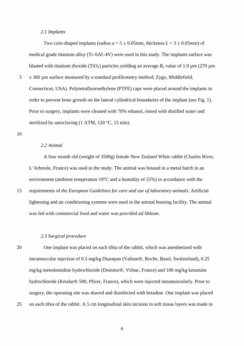
2.1 Implants
Two coin-shaped implants (radius a = 5 ± 0.05mm, thickness L = 3 ± 0.05mm) of
medical grade titanium alloy (Ti–6Al–4V) were used in this study. The implants surface was
blasted with titanium dioxide (TiO2) particles yielding an average Ra value of 1.9 µm (270 µm
x 360 µm surface measured by a standard profilometry method; Zygo, Middlefield, 5
Connecticut, USA). Polytetrafluoroethylene (PTFE) caps were placed around the implants in
order to prevent bone growth on the lateral cylindrical boundaries of the implant (see Fig. 1).
Prior to surgery, implants were cleaned with 70% ethanol, rinsed with distilled water and
sterilized by autoclaving (1 ATM, 120 °C, 15 min).
10
2.2 Animal
A four month old (weight of 3500g) female New Zealand White rabbit (Charles River,
L’Arbresle, France) was used in the study. The animal was housed in a metal hutch in an
environment (ambient temperature 19°C and a humidity of 55%) in accordance with the
requirements of the European Guidelines for care and use of laboratory animals. Artificial 15
lightening and air conditioning systems were used in the animal housing facility. The animal
was fed with commercial food and water was provided ad libitum.
2.3 Surgical procedure
One implant was placed on each tibia of the rabbit, which was anesthetized with 20
intramuscular injection of 0.5 mg/kg Diazepan (Valium®, Roche, Basel, Switzerland), 0.25
mg/kg metedomidine hydrochloride (Domitor®, Virbac, France) and 100 mg/kg ketamine
hydrochloride (Ketalar® 500, Pfizer, France), which were injected intramuscularly. Prior to
surgery, the operating site was shaved and disinfected with betadine. One implant was placed
on each tibia of the rabbit. A 5 cm longitudinal skin incision in soft tissue layers was made to 25
7
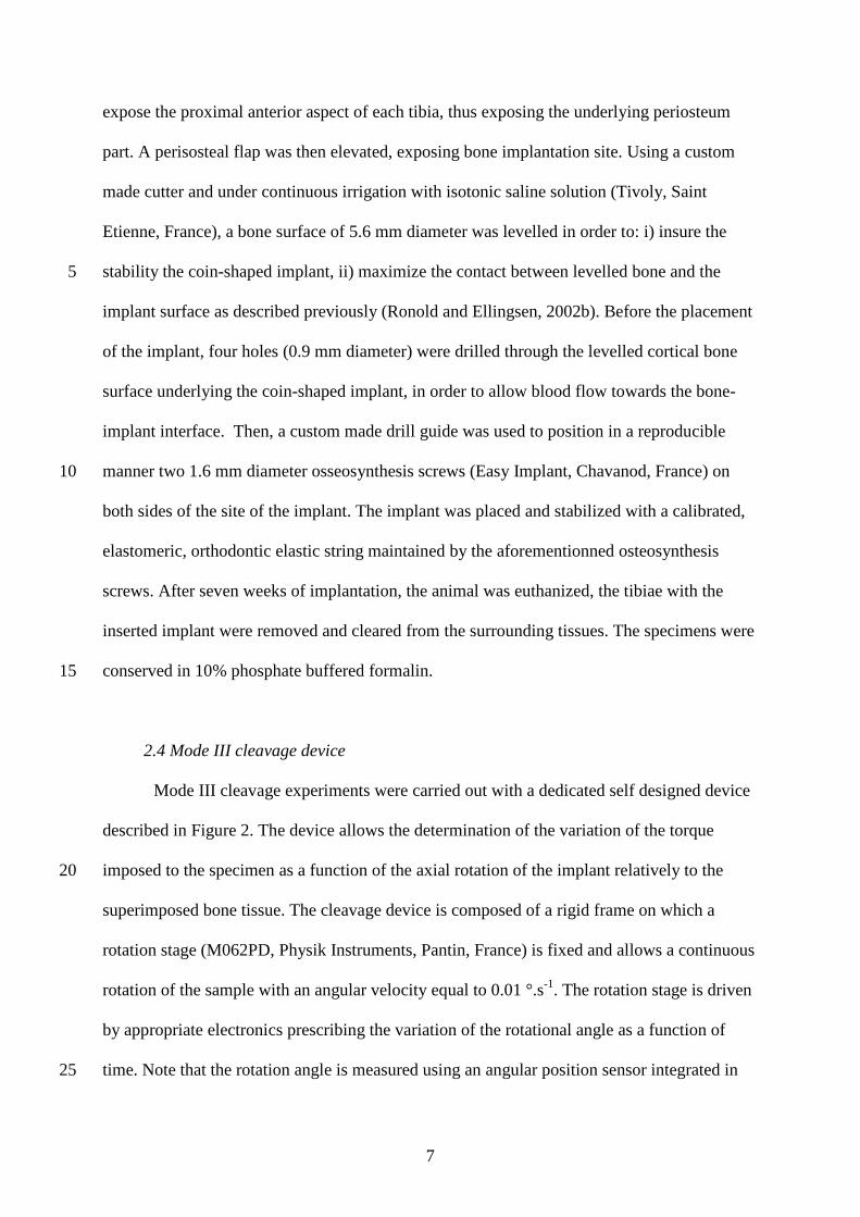
expose the proximal anterior aspect of each tibia, thus exposing the underlying periosteum
part. A perisosteal flap was then elevated, exposing bone implantation site. Using a custom
made cutter and under continuous irrigation with isotonic saline solution (Tivoly, Saint
Etienne, France), a bone surface of 5.6 mm diameter was levelled in order to: i) insure the
stability the coin-shaped implant, ii) maximize the contact between levelled bone and the 5
implant surface as described previously (Ronold and Ellingsen, 2002b). Before the placement
of the implant, four holes (0.9 mm diameter) were drilled through the levelled cortical bone
surface underlying the coin-shaped implant, in order to allow blood flow towards the bone-
implant interface. Then, a custom made drill guide was used to position in a reproducible
manner two 1.6 mm diameter osseosynthesis screws (Easy Implant, Chavanod, France) on 10
both sides of the site of the implant. The implant was placed and stabilized with a calibrated,
elastomeric, orthodontic elastic string maintained by the aforementionned osteosynthesis
screws. After seven weeks of implantation, the animal was euthanized, the tibiae with the
inserted implant were removed and cleared from the surrounding tissues. The specimens were
conserved in 10% phosphate buffered formalin. 15
2.4 Mode III cleavage device
Mode III cleavage experiments were carried out with a dedicated self designed device
described in Figure 2. The device allows the determination of the variation of the torque
imposed to the specimen as a function of the axial rotation of the implant relatively to the 20
superimposed bone tissue. The cleavage device is composed of a rigid frame on which a
rotation stage (M062PD, Physik Instruments, Pantin, France) is fixed and allows a continuous
rotation of the sample with an angular velocity equal to 0.01 °.s-1. The rotation stage is driven
by appropriate electronics prescribing the variation of the rotational angle as a function of
time. Note that the rotation angle is measured using an angular position sensor integrated in 25

8
the rotation stage. A static torque meter (CS 1213B, MEAS-France, Les Clayes sous Bois,
France) records the variation of the torque as a function of the rotation angle through an
electronic sensor interface (9205, Burster, Gernsbach, Germany) (sampling frequency 2.5
kHz). The torque sensor and the rotation stage are synchronized with appropriate electronics
and are both controlled via Labview (National Instruments, Austin, Texas USA). The axes of 5
the torque meter and of the rotation stage are aligned with a 50 µm tolerance.
First, the implant is fixed on the device by a chuck screwed to the torque meter, letting
the bone sample hanging over a container (50* 25*20 mm) tightened in the clamp (Soncini et
al., 2002). Second, the container is filled with a cold hardening resin (Varikleer, Buehler,
Düsseldorf, Germany) allowing to rigidly fix the sample relatively to the rotation stage. This 10
procedure aims at minimising the value of the normal force in order to reduce as far as
practicable its influence on the experimental results. To do so, cold quick hardening resin is
used for the fixation of the samples on the device (Soncini et al., 2002). Third, a thirty
minutes waiting period is needed to allow a full solidification of the resin. Fourth, a 10°
rotation is imposed by the rotation stage with an angular velocity of 0.01°.s-1. The value of 15
10° was chosen to ensure a complete debonding of the bone-implant interface. A post
processing analysis is carried out to extract the data (torque and rotation angle as a function of
time).
3. Analytical modelling 20
In order to understand the experimental results obtained with the cleavage device
described above, an analytical model was considered taking into account the coupling of the
crack propagation (shear mode fracture) between bone and titanium with friction phenomena,
which allows to establish a relationship between the torque and the imposed twist angle. The
shear failure of an adhesive contact during the incipient stages of sliding friction is often 25

9
referred to as a stiction process (Basire and Fretigny, 1999; Goddenhenrich et al., 1994),
which corresponds to a situation where static friction occurs during sliding (Bhushan, 2003).
In friction, stiction corresponds to the initial static loading phase which ends with the total
rupture of the interface leading to full sliding. Since in sliding friction, the friction coefficient
is lower than in static friction, stiction usually results in a force peak (Bowden and Tabor, 5
2001; Chateauminois et al., 2010), as observed herein. A fundamental question is to
determine from the experiments the adhesion energy Γ and the shear modulus µ which rule
the dynamics of crack propagation and its interplay with friction. An approach considering
fracture mechanics concepts allows to consider that the rate of elastic strain energy is equated
to the work done against surface forces, both frictional and adhesive. 10
Figure 3(a) shows a perspective view of the configuration of interest and Fig. 3(b)
shows the expected evolution of the crack front position during the experiment. Let c be the
radius of uncracked region corresponding to the value θ of the twist angle. The notation a
designates the implant radius. er, eθ and ez designate respectively the radial, orthoradial and
axial directions. Five different steps are represented in Fig. 3(b) and correspond, from (i) to 15
(v), to increasing values of the twist angle θ. Here, the crack front is supposed to be circular
and the crack propagation is supposed to be pure mode III (given the geometry of the sample
and the imposed rotation (Ehart et al., 1999)), these assumption being discussed in section 5.
When the twist angle θ increases, the radius c of the circular adhesive region decreases from a
to 0. For all values of θ, the crack front separates the implant surface into two distinct regions. 20
In Fig. 3, the grey regions correspond to the adhesive regions (r<c), while the white regions
correspond to the sliding regions (c<r<a ). In what follows, an elastic behaviour of bone tissue
is assumed throughout crack propagation.
The model has been described in details in a recent paper (Chateauminois et al., 2010)
and is briefly recalled herein. The reader interested in a detailed description should refer to the 25

10
original publication. The main assumption is to consider that the problem is decomposed into
a normal indentation configuration on the one hand and a purely tangential problem on the
other hand. In the present model, we assume that there is no normal force, so that the problem
is only tangential and no cohesive traction is accounted for. This decomposition holds when
the contact boundary conditions are given in terms of stress or strain at the surface. The 5
adhesive contact may be more complex as discussed in (Johnson, 1997) but this aspect is not
considered herein.
During stiction, orthoradial displacements are prescribed within a disk of radius c (the
stick region) while interfacial stresses are prescribed in the sliding region (a>r>c ). The model
described in (Chateauminois et al., 2010) uses a variant of the unified model developed for 10
normal loading (Johnson and Greenwood, 1997; Maugis, 1992) which considers the so-called
Dugdale crack model (Haiat and Barthel, 2007; Haiat et al., 2003). In this description, the
interfacial forces are supposed to be constant up to a given separation distance between the
surfaces. Though rather rough, this model captures the essential features of the adhesive
contact, as more realistic interfacial laws do not modify substantially the results obtained 15
(Barthel, 1998). In (Chateauminois et al., 2010), a variant of this model is adapted for the
twist experiment. Interfacial orthoradial stresses just beyond the stick region are supposed to
be constant up to a radius which corresponds to a given separation distance ∆ between points
on both surfaces. Such an annulus corresponds to the Dugdale region and is defined by
c<r<c *. Adhesion phenomena are accounted for using the adhesion energy Γ between bone 20
and the implant surface. Rupture of the bone-implant interface occurs in the Dugdale annulus
and is modelled by a constant orthoradial stress τD. The problem in the Dugdale annulus is
treated self-consistently. The value of c* is determined by expressing the condition that the
orthoradial displacement reaches the Dugdale limit ∆ at the radius c* and assuming i) that that
the interfacial stress in the Dugdale region is much larger than the friction stress (τD>> τ0) and 25
11
much larger than the shear modulus (τD>>µ ) and ii) a small Dugdale region where ε=(c*-
c)/c<<1, similarly as what was done in (Chateauminois et al., 2010).
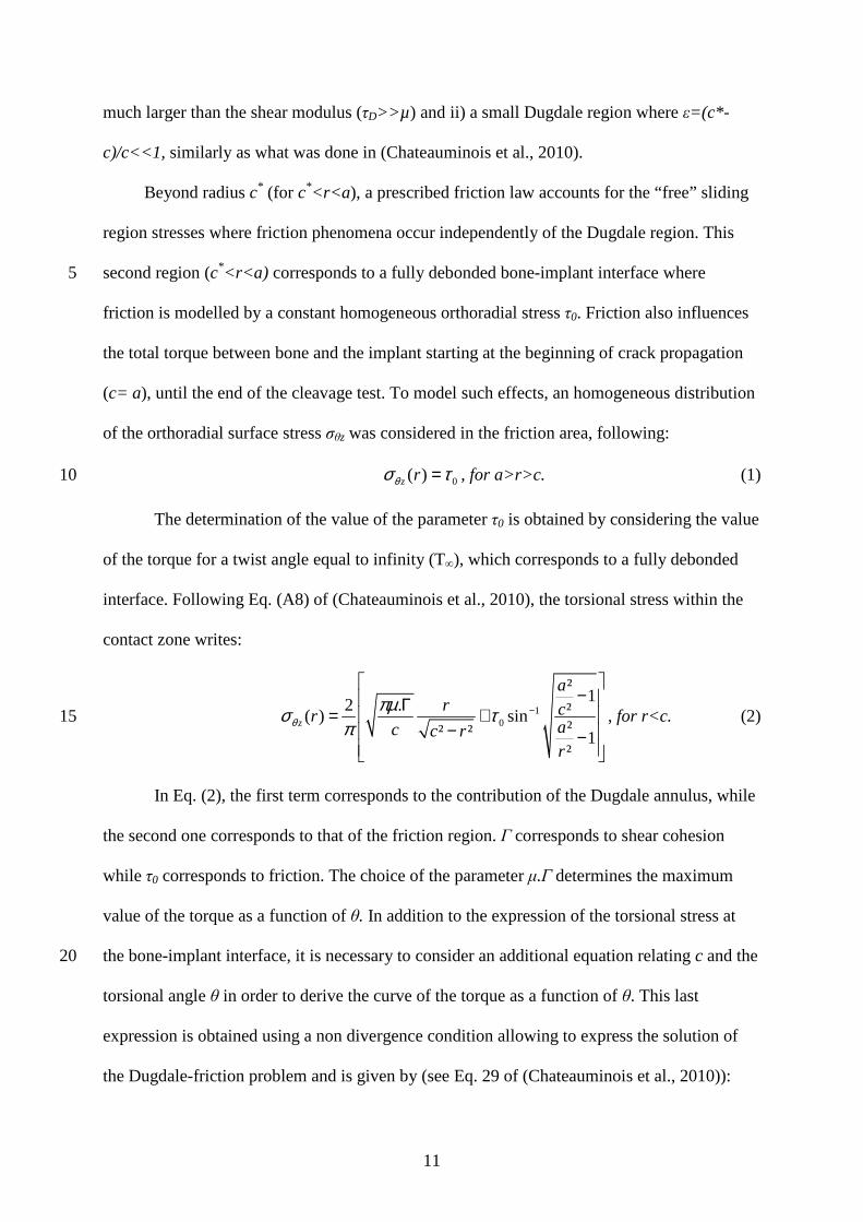
Beyond radius c* (for c*<r<a ), a prescribed friction law accounts for the “free” sliding
region stresses where friction phenomena occur independently of the Dugdale region. This
second region (c*<r<a) corresponds to a fully debonded bone-implant interface where 5
friction is modelled by a constant homogeneous orthoradial stress τ0. Friction also influences
the total torque between bone and the implant starting at the beginning of crack propagation
(c= a), until the end of the cleavage test. To model such effects, an homogeneous distribution
of the orthoradial surface stress σθz was considered in the friction area, following:
0( )z rθσ τ= , for a>r>c. (1) 10
The determination of the value of the parameter τ0 is obtained by considering the value
of the torque for a twist angle equal to infinity (T∞), which corresponds to a fully debonded
interface. Following Eq. (A8) of (Chateauminois et al., 2010), the torsional stress within the
contact zone writes:
10
²12 . ²( ) sin
²² ² 1²
z
ar cr
ac c rr
θπµσ τ
π−
− Γ= +
− −
, for r<c. (2) 15
In Eq. (2), the first term corresponds to the contribution of the Dugdale annulus, while
the second one corresponds to that of the friction region. Γ corresponds to shear cohesion
while τ0 corresponds to friction. The choice of the parameter µ.Γ determines the maximum
value of the torque as a function of θ. In addition to the expression of the torsional stress at
the bone-implant interface, it is necessary to consider an additional equation relating c and the 20
torsional angle θ in order to derive the curve of the torque as a function of θ. This last
expression is obtained using a non divergence condition allowing to express the solution of
the Dugdale-friction problem and is given by (see Eq. 29 of (Chateauminois et al., 2010)):

12
µπ
µτθ
cc
a Γ=− −10 cosh2 . (3)
Coupling Eq. (2) integrated over r and Eq. (3) for different values of c allows to plot the
curve of the resulting moment as a function of the imposed torsional angle θ.
The mode III stress intensity factor KIII is then given by (Maugis, 1999):
2 .IIIK µ= Γ . (4) 5
Note that in the initial stage, the model leads to a linear elastic deformation field
corresponding to a stiffness of bone tissue k given by (Jager, 1995):
316. .
3k aµ= . (5)
4. Results 10
Figure 4 shows a comparison between the experimental results obtained for two
different cleavage experiments (grey solid lines) and the results of the elastic model described
in subsection 3. Figure 4(a) corresponds to the results of the left tibia implant cleavage test
while Figure 4(b) represents the results of the cleavage of the right tibia implant. The value of
the parameter µ.Г is chosen equal to 1.02 GPa.N.m-1 (respectively 0.94 GPa.N.m-1) for the 15
configuration of Fig. 4(a) (respectively Fig. 4(b)) following the maximum value of the torque
of the experimental results. Table 1 shows the different values of µ and Г considered in Fig. 4.
The value of µ equal to 40 MPa (respectively 20 MPa) for left tibia implant (respectively right
tibia implant) gives the best agreement between experimental and analytical results during the
crack propagation stage. However, none of the investigated values of µ allows to predict the 20
variation of the torque as a function of the twist angle. Decreasing the value of µ leads to a
decrease of the initial slope of the torque – twist angle curve during the initial elastic
deformation stage.

13
In order to understand the discrepancy between the experimental and analytical results,
the implants surfaces were observed using standard light microscopy. Figure 5 represents post
mortem images of both samples. Figure 5(a) shows the titanium surface of left tibia implant
and Fig. 5(b) shows the titanium surface of right tibia implant after the cleavage test. As
shown in Fig. 5, scarce fragments of bone tissue remain attached to the titanium surface after 5
the cleavage test. The results show that the interface fracture modes are mixed and may be
adhesive (in implant regions where no bone tissue is attached to the implant surface) or
cohesive (when some bone tissue remains attached to the implant surface). Moreover, Fig. 5
shows the heterogeneous nature of bone remodelling phenomena around the implant surface,
indicating that adhesion phenomena occurred over a limited portion of the implant surface. 10
The adhesion properties are not homogeneous and some regions of the implant exhibit low (or
even possibly no) adhesion energy, while some other regions have higher adhesion energy,
which may be due to inhomogeneous remodelling phenomena.
15
5. Discussion
This work constitutes the first study proposing the use of experimental mode III
cleavage tests to investigate the biomechanical strength of the interface of cementless
implants. This study is also the first one to provide a measurement of the Mode III stress
intensity factor and fracture energy of the bone implant interface. The originality of the 20
present study consists in coupling experimental surgery with advanced biomechanical testing
and analytical modelling to describe the behaviour of the bone-implant interface during crack
propagation. In this study, coin-shaped titanium implants were inserted on the tibiae of a New
Zealand White female rabbit. After euthanasia, bone samples were removed and mode III
cleavage tests were realised. 25
14
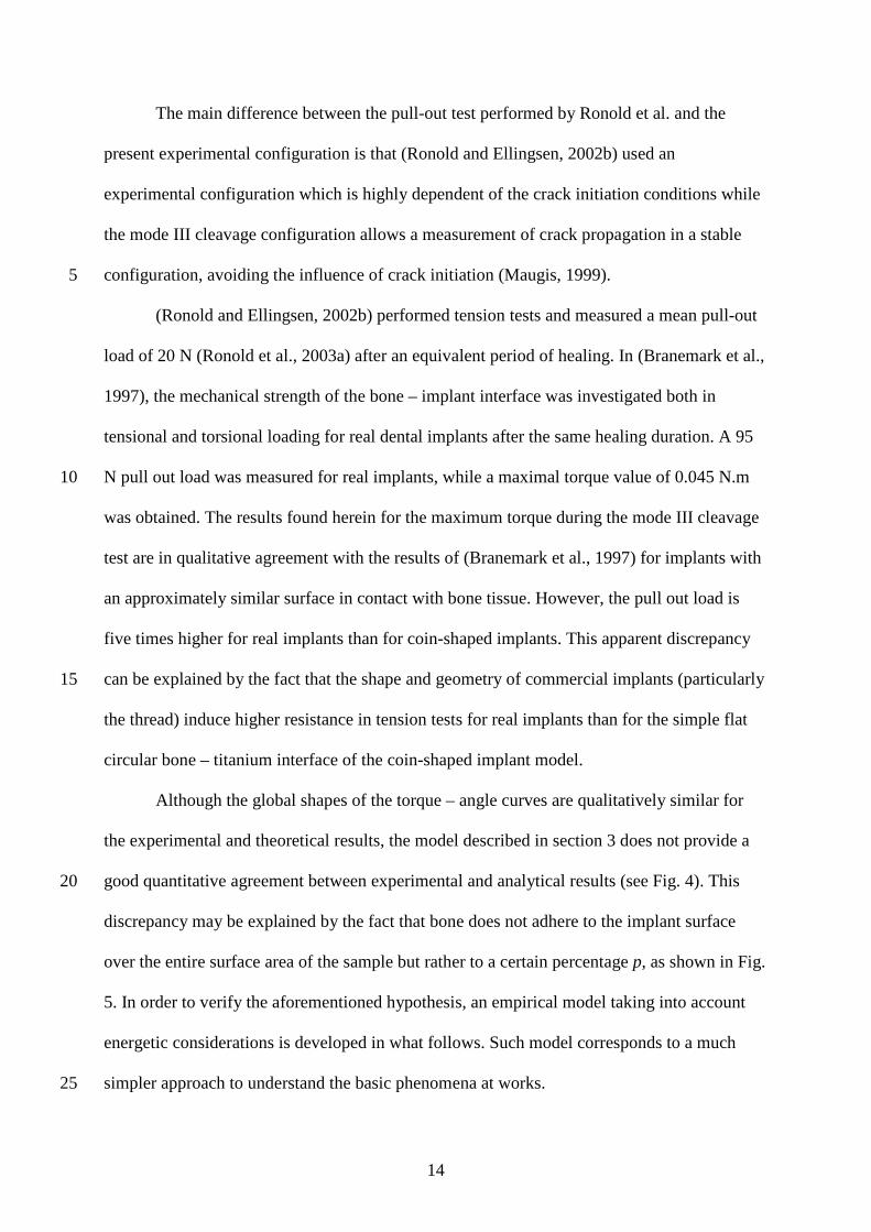
The main difference between the pull-out test performed by Ronold et al. and the
present experimental configuration is that (Ronold and Ellingsen, 2002b) used an
experimental configuration which is highly dependent of the crack initiation conditions while
the mode III cleavage configuration allows a measurement of crack propagation in a stable
configuration, avoiding the influence of crack initiation (Maugis, 1999). 5
(Ronold and Ellingsen, 2002b) performed tension tests and measured a mean pull-out
load of 20 N (Ronold et al., 2003a) after an equivalent period of healing. In (Branemark et al.,
1997), the mechanical strength of the bone – implant interface was investigated both in
tensional and torsional loading for real dental implants after the same healing duration. A 95
N pull out load was measured for real implants, while a maximal torque value of 0.045 N.m 10
was obtained. The results found herein for the maximum torque during the mode III cleavage
test are in qualitative agreement with the results of (Branemark et al., 1997) for implants with
an approximately similar surface in contact with bone tissue. However, the pull out load is
five times higher for real implants than for coin-shaped implants. This apparent discrepancy
can be explained by the fact that the shape and geometry of commercial implants (particularly 15
the thread) induce higher resistance in tension tests for real implants than for the simple flat
circular bone – titanium interface of the coin-shaped implant model.
Although the global shapes of the torque – angle curves are qualitatively similar for
the experimental and theoretical results, the model described in section 3 does not provide a
good quantitative agreement between experimental and analytical results (see Fig. 4). This 20
discrepancy may be explained by the fact that bone does not adhere to the implant surface
over the entire surface area of the sample but rather to a certain percentage p, as shown in Fig.
5. In order to verify the aforementioned hypothesis, an empirical model taking into account
energetic considerations is developed in what follows. Such model corresponds to a much
simpler approach to understand the basic phenomena at works. 25
15
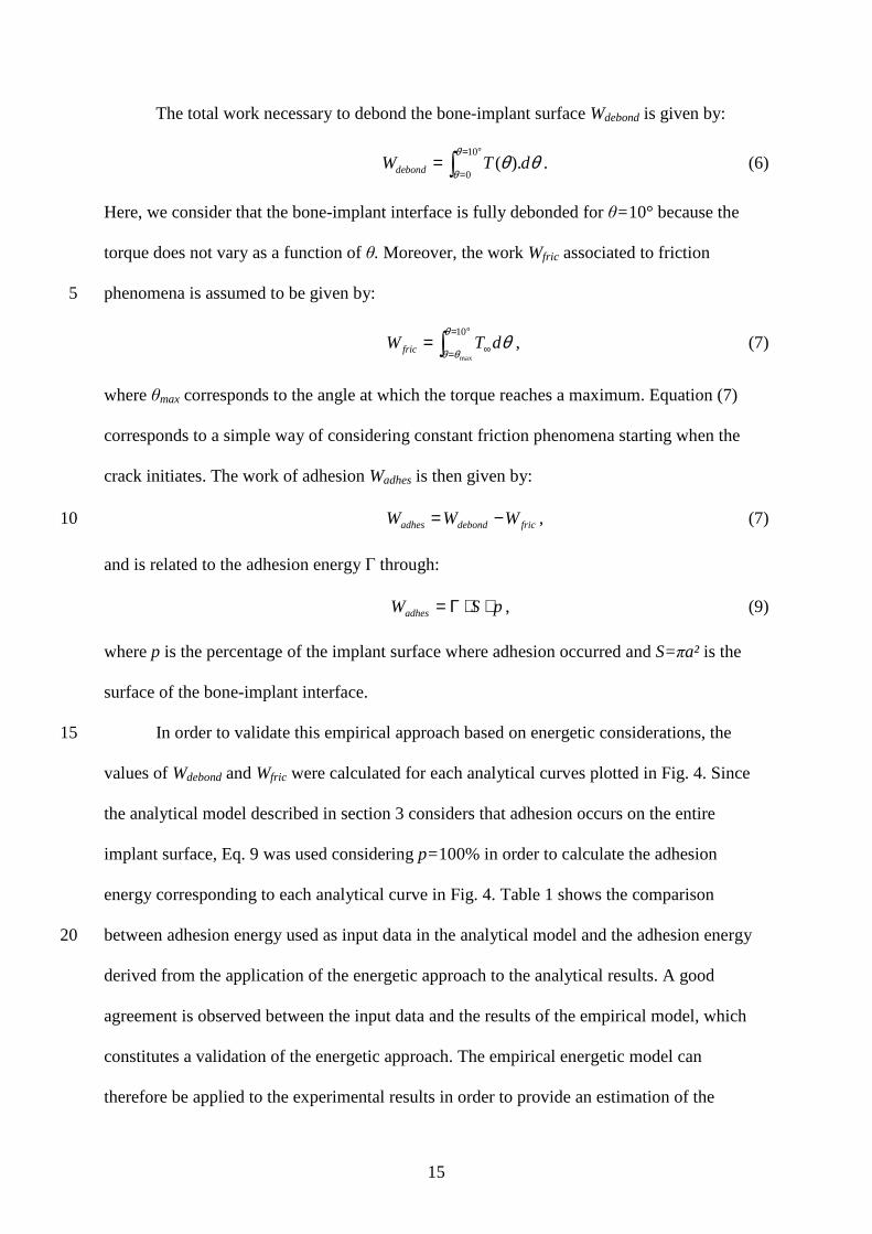
The total work necessary to debond the bone-implant surface Wdebond is given by:
10
0( ).debondW T d
θ
θθ θ
= °
== ∫ . (6)
Here, we consider that the bone-implant interface is fully debonded for θ=10° because the
torque does not vary as a function of θ. Moreover, the work Wfric associated to friction
phenomena is assumed to be given by: 5
∫°=
= ∞=10
max
θ
θθθdTWfric , (7)
where θmax corresponds to the angle at which the torque reaches a maximum. Equation (7)
corresponds to a simple way of considering constant friction phenomena starting when the
crack initiates. The work of adhesion Wadhes is then given by:
fricdebondadhes WWW −= , (7) 10
and is related to the adhesion energy Γ through:
pSWadhes ⋅⋅Γ= , (9)
where p is the percentage of the implant surface where adhesion occurred and S=πa² is the
surface of the bone-implant interface.
In order to validate this empirical approach based on energetic considerations, the 15
values of Wdebond and Wfric were calculated for each analytical curves plotted in Fig. 4. Since
the analytical model described in section 3 considers that adhesion occurs on the entire
implant surface, Eq. 9 was used considering p=100% in order to calculate the adhesion
energy corresponding to each analytical curve in Fig. 4. Table 1 shows the comparison
between adhesion energy used as input data in the analytical model and the adhesion energy 20
derived from the application of the energetic approach to the analytical results. A good
agreement is observed between the input data and the results of the empirical model, which
constitutes a validation of the energetic approach. The empirical energetic model can
therefore be applied to the experimental results in order to provide an estimation of the

16
adhesion energy. To do so, a simple analysis of the images of the debonded surfaces (see Fig.
5) allowed to estimate the value of p for each sample. The results are given in Table 2. Wdebond
and Wfric were calculated for the two experimental curves and Eqs. 8-9 were then used in
order to provide an estimation of the adhesion energy for each implant. Table 2 shows the
results obtained for the values of Wadhes, Wdebond, Γ, Wfric and p. 5
The values of the bone stiffness k were deduced from the initial slope of the torque –
angle curve during the linear elasticity stage and the values of the shear modulus µ were
deduced from the values of k using Eq. 5. The results are also summarized in Table 2 for each
implant.
In the literature, (Berzins et al., 1997) proposed an experimental methodology to 10
estimate the shear modulus of the bone – implant interface in vitro using pull-out tests. The
same methodology was used by (Muller et al., 2006) with cylindrical implants inserted in
New Zealand White rabbits. The results showed mean values of shear modulus of newly
formed bone tissue varying between 25 and 40 MPa, which is lower than the results obtained
in the present study. However, the present experimental configuration is fundamentally 15
different since we consider a steady state crack propagation configuration. Moreover, the
mean value for shear modulus in mature cortical bone is equal to 3.5 GPa (Laugier and Haiat,
2011). This difference may be explained by the degree of mineralisation of mature cortical
bone which is higher in mature cortical bone than in newly formed bone tissue (Mathieu et al.,
2011) and by the fact that the bone-implant contact is usually comprised between 30 and 70% 20
(Branemark et al., 1997; Marin et al., 2010).
The values of shear modulus of Ti-6Al-4V and of PMMA found in the literature are
equal to 42.3 GPa (Pattijn et al., 2007) and 1.1 GPa (Royer and Dieulesaint, 1996)
respectively. The shear moduli of Ti-6Al-4V and of PMMA are significantly higher than the
values of µ found herein (230-250 MPa), which justifies the assumption of neglecting the 25

17
deformation of the implant and of the resin. The torsional rigidity of the device is a critical
point in order to assess accurately the bone shear modulus. The critical component in the
experimental device is the static torque meter, which has a torsional rigidity equal to 273
N.m.rad-1 (constructor data). This value is about 15 times superior to the highest value of
torsional stiffness derived from the analytical model. As a consequence, it is assumed that the 5
torsional rigidity of the device does not significantly affect the accuracy of the measurement.
During functional loading, the bone – implant interface is subjected to multiaxial
stresses (traction, compression and torsion loadings) (Butz et al., 2006). Therefore, mode I
cleavage testing (Morais et al., 2010) could also be an interesting approach, but would
necessitate the development of another implant model with a rectangular flat bone – implant 10
interface in order to have a constant length of the crack front. Mode I fracture characterization
has been investigated by (Morais et al., 2010) in cortical bone (no implant present in bone),
following an approach described by (de Moura et al., 2008), leading to a value of mode I
stress intensity factor KI in average equal to 6.17 MPa.m1/2 for hydrated cortical bone. It
would be of interest to compare these results of KI for cortical bone with mode I cleavage 15
strength of the bone – implant interface.
This study has several limitations. First, only two samples were considered due to the
complexity of the surgical procedure, which makes it impossible to consider the scatter of the
mechanical properties derived from the experiments. Therefore, special care is needed for the
interpretation of the values of such parameters estimated with our method. However, the two 20
experimental curves are qualitatively similar and the results obtained for both samples are of
the same order of magnitude.
Secondly, the estimation of the mechanical properties of interest results from
necessary multiple approximations and parameters adjustments. Several limitations apply to
the analytical model, which assumes an isotropic behaviour of bone tissue while bone tissue is 25

18
a highly anisotropic material. Based on the geometrical configuration of testing (Ehart et al.,
1999), the model assumes a pure mode III crack propagation, which is supported by Fig. 5
showing that the crack plane is approximately parallel to the implant surface. Moreover, the
model assumes a homogeneous distribution of the mechanical properties at the implant
surface. However, the remaining normal force may induce mixed mode propagation and Fig. 5
5 shows that remodelling phenomena at the bone implant interface occur in a non uniform
manner (failure involving a material as heterogeneous as bone is likely to be stochastic and
heterogeneous), which might complicate crack propagation and lead to mixed modes crack
propagation due to the rupture of symmetry (Koester et al., 2011; Zimmermann et al., 2009;
Zimmermann et al., 2010). 10
Third, a simplistic model of friction is considered herein and spatiotemporal variations
of friction properties may occur due to wear phenomena (Younesi et al., 2010). The
visualisation of the evolution of the crack front during the mechanical cleavage test could help
to account for more realistic situations in the model. However, such measurement is not
possible at the current stage of development of the experimental device, because of the 15
opacity of bone tissue and titanium. The difference between of the torque obtained with the
models compared to the experimental results may be explained by the aforementioned
limitations.
Fourth, the normal force arising due to the expansion of the volume of the cold
hardening resin during the polymerization process is not measured and may affect the 20
measurements and influence friction phenomena. However, the use of such a resin in order to
attach the sample to the device allows to minimize the mechanical stresses applied to the
bone-implant interface (Soncini et al., 2002). Moreover, monitoring of the torque imposed to
the sample during the resin hardening reports values lower than the sensitivity of the torque
sensor (<10-3 N.m). The normal force cannot be controlled nor measured in the present 25

19
version of the device and future work should include such measurement, which could provide
important information about the friction phenomena occurring at the bone – implant interface
and allow distinguishing the respective contributions of crack propagation and friction
phenomena. However, the effect of the normal force should be the same for the two samples
because identical experimental conditions were reproduced for the two mechanical tests 5
(orientation of the sample, shape of the container, volume of injected resin).
6. Conclusion
A mode III cleavage testing configuration allows to investigate the behaviour of the
bone-implant interface because the implant is routinely exposed to torsional stresses in vivo 10
(hip prosthesis, dental implant). The combination of the developed analytical model together
with partial adhesive contact at the bone-implant interface enables to explain the results
obtained during the interface debonding. Stiffness, shear modulus, maximal torsional load and
mode III stress intensity factors are good candidates for a quantitative assessment of the
resistance of the implant to shear stresses. Our approach could provide accurate indicators for 15
the development and the optimization of implant material, surface treatment and medical
treatment investigations.
Acknowledgements
The authors acknowledge the support of the Direction Générale de l’Armement and of 20
the Centre National de la Recherche Scientifique through the PhD study of VM. The support
of the ED SIE of Université Paris-Est is also acknowledged. The authors acknowledge the
support of the Institut des sciences de l'ingénierie et des systèmes (INSIS) of the CNRS
through a PEPS funding for the project “BioMatSon”. The authors acknowledge the support
20
of the French National Agency through the support of the WaveImplant project (AAP
Emergence).
21
References
Albrektsson, T., Dahl, E., Enbom, L., Engevall, S., Engquist, B., Eriksson, A.R., Feldmann,
G., Freiberg, N., Glantz, P.O., Kjellman, O., Kristersson, L., Kvint, S., Kondell, P.A.,
Palmquist, J., Werndahl, L., Astrand, P., 1988. Osseointegrated Oral Implants - a Swedish 5
Multicenter Study of 8139 Consecutively Inserted Nobelpharma Implants. J Periodont 59,
287-296.
Barthel, E., 1998. On the description of the adhesive contact of spheres with arbitrary
interaction potentials. J Colloid Interface Sci 200, 7-18.
Basire, C., Fretigny, C., 1999. Determination of viscoelastic moduli at a submicrometric scale. 10
Eur Phys J-Appl Phys 6, 323-329.
Berzins, A., Shah, B., Weinans, H., Sumner, D.R., 1997. Nondestructive measurements of
implant-bone interface shear modulus and effects of implant geometry in pull-out tests. J
Biomed Mater Res 34, 337-340.
Bhushan, B., 2003. Adhesion and stiction: Mechanisms, measurement techniques, and 15
methods for reduction. J Vac Sci Technol B 21, 2262.
Bowden, F.P., Tabor, D., 2001. The friction and lubrification of solids, Volume 1. Oxford
University Press.
Branemark, R., Ohrnell, L.O., Nilsson, P., Thomsen, P., 1997. Biomechanical characterization
of osseointegration during healing: An experimental in vivo study in the rat. Biomaterials 18, 20
969-978.
Branemark, R., Ohrnell, L.O., Skalak, R., Carlsson, L., Branemark, P.I., 1998. Biomechanical
characterization of osseointegration: An experimental in vivo investigation in the beagle dog.
J Orthop Res 16, 61-69.
22
Branemark, R., Skalak, R., 1998. An in-vivo method for biomechanical characterization of
bone-anchored implants. Med Eng Phys 20, 216-219.
Buser, D., Dula, K., Lang, N.P., Nyman, S., 1996. Long-term stability of osseointegrated
implants in bone regenerated with the membrane technique - 5-year results of a prospective
study with 12 implants. Clin Oral Implant Res 7, 175-183. 5
Butz, F., Aita, H., Wang, C.J., Ogawa, T., 2006. Harder and stiffer bone Osseointegrated to
roughened titanium. J Dent Res 85, 560-565.
Chateauminois, A., Fretigny, C., Olanier, L., 2010. Friction and shear fracture of an adhesive
contact under torsion. Phys Rev E 81, 12.
Cook, S.D., Barrack, R.L., Dalton, J.E., Thomas, K.A., Brown, T.D., 1995. Effects of 10
Indomethacin on Biologic Fixation of Porous-Coated Titanium Implants. J Arthroplast 10,
351-358.
de Moura, M., Morais, J.J.L., Dourado, N., 2008. A new data reduction scheme for mode I
wood fracture characterization using the double cantilever beam test. Eng Fract Mech 75,
3852-3865. 15
Duyck, J., Vandamme, K., Geris, L., Van Oosterwyck, H., De Cooman, M., Vandersloten, J.,
Puers, R., Naert, I., 2006. The influence of micro-motion on the tissue differentiation around
immediately loaded cylindrical turned titanium implants. Arch Oral Biol 51, 1-9. .
Edwards, J.T., Brunski, J.B., Higuchi, H.W., 1997. Mechanical and morphologic investigation
of the tensile strength of a bone-hydroxyapatite interface. J Biomed Mater Res 36, 454-468. 20
Ehart, R.J.A., Stanzl-Tschegg, S.E., Tschegg, E.K., 1999. Mode III fracture energy of wood
composites in comparison to solid wood. Wood Sci Technol 33, 391-405.
Ellingsen, J.E., 2000. Surface configurations of dental implants. Periodontol 17, 36-46.
23
Franchi, M., Bacchelli, B., Giavaresi, G., De Pasquale, V., Martini, D., Fini, M., Giardino, R.,
Ruggeri, A., 2007. Influence of different implant surfaces on peri-implant osteogenesis:
Histomorphometric analysis in sheep. J Periodont 78, 879-888.
Giavaresi, G., Fini, M., Cigada, A., Chiesa, R., Rondelli, G., Rimondini, L., Torricelli, P.,
Aldini, N.N., Giardino, R., 2003. Mechanical and histomorphometric evaluations of titanium 5
implants with different surface treatments inserted in sheep cortical bone. Biomaterials 24,
1583-1594.
Goddenhenrich, T., Muller, S., Heiden, C., 1994. A Lateral Modulation Technique for
Simultaneous Friction and Topography Measurements with the Atomic-Force Microscope.
Rev Sci Instrum 65, 2870-2873. 10
Goodacre, C.J., Kan, J.Y.K., Rungcharassaeng, K., 1999. Clinical complications of
osseointegrated implants. J Prosthet Dent 81, 537-552.
Gotfredsen, K., Berglundh, T., Lindhe, J., 2001. Bone reactions adjacent to titanium implants
subjected to static load of different duration. A study in the dog (III). Clin Oral Implants Res
12, 552-558. 15
Haiat, G., Barthel, E., 2007. An approximate model for the adhesive contact of rough
viscoelastic surfaces. Langmuir 23, 11643-11650.
Haiat, G., Huy, M.C.P., Barthel, E., 2003. The adhesive contact of viscoelastic spheres. J
Mech Phys Solids 51, 69-99.
Jager, J., 1995. Axisymmetrical Bodies of Equal Material in Contact under Torsion or Shift. 20
Arch Appl Mech 65, 478-487.
Jinno, T., Goldberg, V.M., Davy, D., Stevenson, S., 1998. Osseointegration of surface-blasted
implants made of titanium alloy and cobalt-chromium alloy in a rabbit intramedullary model.
J Biomed Mater Res 42, 20-29.

24
Johansson, L., Peng, F., Simonson, R., 1999. Mechanical fiber separation under torsional
stress. Wood Sci Technol 33, 43-54.
Johnson, K.L., 1997. Adhesion and friction between a smooth elastic spherical asperity and a
plane surface. Proc R Soc London Ser A-Math Phys Eng Sci 453, 163-179.
Johnson, K.L., Greenwood, J.A., 1997. An adhesion map for the contact of elastic spheres. J 5
Colloid Interface Sci 192, 326-333.
Koester, K.J., Barth, H.D., Ritchie, R.O., 2011. Effect of aging on the transverse toughness of
human cortical bone: Evaluation by R-curves. J Mech Behav Biomed Mater 4, 1504-1513.
Laugier, P., Haiat, G., 2011. Bone quantitative ultrasound. Springer.
Marin, C., Granato, R., Suzuki, M., Janal, M.N., Gil, J.N., Nemcovsky, C., Bonfante, E.A., 10
Coelho, P.G., 2010. Biomechanical and histomorphometric analysis of etched and non-etched
resorbable blasting media processed implant surfaces: An experimental study in dogs. J Mech
Behav Biomed Mater 3, 382-391.
Mathieu, V., Fukui, K., Matsukawa, M., Kawabe, M., Vayron, R., Soffer, E., Anagnostou, F.,
Haiat, G., 2011. Micro-Brillouin scattering measurements in mature and newly formed bone 15
tissue surrounding an implant. J Biomech Eng 133, 021006-1-6.
Maugis, D., 1992. Adhesion of Spheres - the Jkr-Dmt Transition Using a Dugdale Model. J
Colloid Interface Sci 150, 243-269.
Maugis, D., 1999. Contact, Adhesion and Rupture of Elastic Solids.
Maugis, D., 2000. Frictionless Elastic Contact, Contact adhesion and rupture of elastic solids. 20
Springer, p. 236.
Miller, M.A., Race, A., Waanders, D., Cleary, R., Janssen, D., Verdonschot, N., Mann, K.A.,
2011. Multi-axial loading micromechanics of the cement-bone interface in postmortem
retrievals and lab-prepared specimens. J Mech Behav Biomed Mater 4, 366-374.
25
Morais, J.J.L., de Moura, M., Pereira, F.A.M., Xavier, J., Dourado, N., Dias, M.I.R., Azevedo,
J.M.T., 2010. The double cantilever beam test applied to mode I fracture characterization of
cortical bone tissue. J Mech Behav Biomed Mater 3, 446-453.
Muller, M., Hennig, F.F., Hothorn, T., Stangl, R., 2006. Bone-implant interface shear
modulus and ultimate stress in a transcortical rabbit model of open-pore Ti6Al4V implants. J 5
Biomech 39, 2123-2132.
Nakamura, T., Yamamuro, T., Higashi, S., Kokubo, T., Itoo, S., 1985. A new glass-ceramic
for bone replacement: evaluation of its bonding to bone tissue. J Biomed Mater Res 19, 685-
698.
O'Brien, F.J., Taylor, D., Lee, T.C., 2002. An improved labelling technique for monitoring 10
microcrack growth in compact bone. J Biomech 35, 523-526.
O'Brien, F.J., Taylor, D., Lee, T.C., 2003. Microcrack accumulation at different intervals
during fatigue testing of compact bone. J Biomech 36, 973-980.
Ogawa, T., Ozawa, S., Shih, J.H., Ryu, K.H., Sukotjo, C., Yang, J.M., Nishimura, I., 2000.
Biomechanical evaluation of osseous implants having different surface topographies in rats. J 15
Dent Res 79, 1857-1863.
Ogiso, M., Yamamura, M., Kuo, P.T., Borgese, D., Matsumoto, T., 1998. Comparative push-
out test of dense HA implants and HA-coated implants: findings in a canine study. J Biomed
Mater Res 39, 364-372.
Orlik, J., Zhurov, A., Middleton, J., 2003. On the secondary stability of coated cementless hip 20
replacement: parameters that affected interface strength. Med Eng Phys 25, 825-831.
Pattijn, V., Jaecques, S.V.N., De Smet, E., Muraru, L., Van Lierde, C., Van der Perre, G.,
Naert, I., Sloten, J.V., 2007. Resonance frequency analysis of implants in the guinea pig
model: Influence of boundary conditions and orientation of the transducer. Med Eng Phys 29,
182-190. 25
26
Ronold, H.J., Ellingsen, J.E., 2002a. Effect of micro-roughness produced by TiO2 blasting -
tensile testing of bone attachment by using coin-shaped implants. Biomaterials 23, 4211-4219.
Ronold, H.J., Ellingsen, J.E., 2002b. The use of a coin shaped implant for direct in situ
measurement of attachment strength for osseointegrating biomaterial surfaces. Biomaterials
23, 2201-2209. 5
Ronold, H.J., Ellingsen, J.E., Lyngstadaas, S.P., 2003a. Tensile force testing of optimized
coin-shaped titanium implant attachment kinetics in the rabbit tibiae. J Mater Sci-Mater Med
14, 843-849.
Ronold, H.J., Lyngstadaas, S.P., Ellingsen, J.E., 2003b. Analysing the optimal value for
titanium implant roughness in bone attachment using a tensile test. Biomaterials 24, 4559-10
4564.
Ronold, H.J., Lyngstadaas, S.P., Ellingsen, J.E., 2003c. A study on the effect of dual blasting
with Tio(2) on titanium implant surfaces on functional attachment in bone. J Biomed Mater
Res Part A 67A, 524-530.
Royer, D., Dieulesaint, E., 1996. Elastic waves in solids I: free and guided propagation. 15
Schwartz, Z., Nasazky, E., Boyan, B.D., 2005. Surface microtopography regulates
osteointegration: the role of implant surface microtopography in osteointegration. Masson,
Paris.
Seong, W.J., Kim, U.K., Swift, J.Q., Hodges, J.S., Ko, C.C., 2009. Correlations between
Physical Properties of Jawbone and Dental Implant Initial Stability. J Prosthet Dent 101, 306-20
318.
Shalabi, M.M., Gortemaker, A., Van't Hof, M.A., Jansen, J.A., Creugers, N.H., 2006. Implant
surface roughness and bone healing: a systematic review. J Dent Res 85, 496-500.
Shirazi-Adl, A., 1992. Finite element stress analysis of a push-out test. Part 1: Fixed interface
using stress compatible elements. J Biomech Eng 114, 111-118. 25

27
Skripitz, R., Aspenberg, P., 1998. Tensile bond between bone and titanium: a reappraisal of
osseointegration. Acta Orthop Scand 69, 315-319.
Skripitz, R., Aspenberg, P., 1999. Attachment of PMMA cement to bone: force measurements
in rats. Biomaterials 20, 351-356.
Soncini, M., Baena, R.R., Pietrabissa, R., Quaglini, V., Rizzo, S., Zaffe, D., 2002. 5
Experimental procedure for the evaluation of the mechanical properties of the bone
surrounding dental implants. Biomaterials 23, 9-17.
Stoppie, N., Van Oosterwyck, H., Jansen, J., Wolke, J., Wevers, M., Naert, I., 2008. The
influence of Young's modulus of loaded implants on bone remodeling: An experimental and
numerical study in the goat knee. J Biomed Mater Res A 9, 9. 10
Taborelli, M., Jobin, M., Francois, P., Vaudaux, P., Tonetti, M., Szmukler-Moncler, S.,
Simpson, J.P., Descouts, P., 1997. Influence of surface treatments developed for oral implants
on the physical and biological properties of titanium. (I) Surface characterization. Clin Oral
Implants Res 8, 208-216.
Taylor, D., O'Reilly, P., Vallet, L., Lee, T.C., 2003. The fatigue strength of compact bone in 15
torsion. J Biomech 36, 1103-1109.
Vercaigne, S., Wolke, J.G., Naert, I., Jansen, J.A., 1998. Histomorphometrical and
mechanical evaluation of titanium plasma-spray-coated implants placed in the cortical bone of
goats. J Biomed Mater Res 41, 41-48.
Younesi, M., Bahrololoom, M.E., Fooladfar, H., 2010. Development of wear resistant NFSS-20
HA novel biocomposites and study of their tribological properties for orthopaedic
applications. J Mech Behav Biomed Mater 3, 178-188.
Zimmermann, E.A., Launey, M.E., Barth, H.D., Ritchie, R.O., 2009. Mixed-mode fracture of
human cortical bone. Biomaterials 30, 5877-5884.

28
Zimmermann, E.A., Launey, M.E., Ritchie, R.O., 2010. The significance of crack-resistance
curves to the mixed-mode fracture toughness of human cortical bone. Biomaterials 31, 5297-
5305.
29
Figure Captions:
Figure 1: Schematic representation of the surgical model.
Figure 2: Schematic representation of the mode III cleavage test device. 5
Figure 3: Description of the crack propagation configuration. (a): perspective view of the
configuration of interest, (b): evolution of the crack front position during the experiment. c is
the radius of the uncracked region corresponding to the value θ of twist angle. a designates
the radius of the implant. er, eθ and ez designates respectively the radial, orthoradial and axial 10
directions. Five different steps are represented and correspond, from (i) to (v), to increasing
values of the twist angle θ. The grey areas correspond to the adhesive regions, while the white
ones correspond to the sliding regions.
Figure 4: Total torque measured experimentally (grey solid line) and calculated from the 15
analytical elastic model as a function of the imposed twist angle for different values of shear
modulus µ: left tibia implant (a) and right tibia implant (b).
Figure 5: Post mortem images of both samples. (a): left tibia implant and (b): right tibia
implant. Both images were obtained by standard light microscopy. 20

30
Figure 1
Figure 2 5

31
Figure 3

32
Figure 4

33
Figure 5