Mode I stress intensity factors of sickle-shaped surface ...ijame.ump.edu.my/images/Volume 13 Issue...
16
International Journal of Automotive and Mechanical Engineering (IJAME) ISSN: 2229-8649 (Print); ISSN: 2180-1606 (Online); Volume 13, Issue 2 pp. 3329 - 3344, September 2016 ©Universiti Malaysia Pahang Publishing DOI: https://doi.org/10.15282/ijame.13.2.2016.4.0276 3329 Mode I stress intensity factors of sickle-shaped surface cracks in round solid bars under bending moment Al Emran Ismail Faculty of Mechanical and Manufacturing Engineering Universiti Tun Hussein Onn Malaysia, 86400 Batu Pahat, Johor, Malaysia Email: [email protected] / [email protected] Phone: +6074537675; Fax: +6074536080 ABSTRACT Sickle-shaped crack may occur on the surface of solid round cylinder under some specific reasons such as design discontinuities or material defects. This type of crack is capable to grow circumferentially around the bar and it is called a sickle-shaped surface cracks. The complete solution of stress intensity factors (SIF) of sickle-shaped surface cracks is hard to find and therefore the objective of this paper is to present the behaviour of these cracks under remotely applied bending moment. In order to understand the role of these cracks, there are seven crack aspect ratios, a/b considered, ranging from 0.0 to 1.2. For each crack aspect ratio, there are six relative crack depths, a/D used ranging from 0.1 to 0.6. ANSYS finite element program is used to model the crack. Stress intensity factor (SIF) which is based on the J-integral is used to characterize the cracks. For relatively shallow cracks (a/D 0.3), the role of SIFs along the crack front is insignificant regardless of a/b. However, for the deeper cracks (a/D > 0.3), the effect of a/b is tremendous on the SIFs. If a/b is increased from 0.0 to 1.2, higher SIFs are obtained around the central compared with the outer regions of the crack fronts. This is due to the fact that the circumferential cracks at both sides of the bar experience lack of mode I opening mechanism compared with the crack faces at the upper side cracks. It is suggested that the phenomena of crack closure are not only caused by the plastic deformation, surface roughness and other related factors but the shape of crack also plays an important role. Keywords: Sickle-Shaped Crack; Surface Cracks; Round Solid Bars; Bending Moment. INTRODUCTION Crack is one of the biggest problems in all engineering fields leading to premature failures. There are several factors affecting the formation of cracks, for example material defects [1] and mechanical discontinuities [2-12]. There are tremendous numbers of work focused on such cracks [13-16]. Toribio, Matos [13] studied the effect of crack aspect ratio changes with the relative crack depth by considering the Paris- Erdogan law. It is found that for crack depth between 0.7 to 0.8 diameter, the crack shape evolution is slightly increasing for free sample ends and decreasing for constrained ends. Śnieżek, Ślęzak [14] experimentally investigated the propagation of semi-elliptical surface cracks of austenitic steel. For rectangular-shaped samples, it is confirmed that fatigue crack propagation takes the shapes of semi-ellipse before the final failure occurs. Coules [15] also successfully used semi-elliptical shaped surface cracks in analyzing the interaction between two dissimilar surface cracks. Surface
Transcript of Mode I stress intensity factors of sickle-shaped surface ...ijame.ump.edu.my/images/Volume 13 Issue...

International Journal of Automotive and Mechanical Engineering (IJAME)
ISSN: 2229-8649 (Print); ISSN: 2180-1606 (Online);
Volume 13, Issue 2 pp. 3329 - 3344, September 2016
©Universiti Malaysia Pahang Publishing
DOI: https://doi.org/10.15282/ijame.13.2.2016.4.0276
3329
Mode I stress intensity factors of sickle-shaped surface cracks in round solid bars
under bending moment
Al Emran Ismail
Faculty of Mechanical and Manufacturing Engineering
Universiti Tun Hussein Onn Malaysia, 86400 Batu Pahat, Johor, Malaysia
Email: [email protected] / [email protected]
Phone: +6074537675; Fax: +6074536080
ABSTRACT
Sickle-shaped crack may occur on the surface of solid round cylinder under some
specific reasons such as design discontinuities or material defects. This type of crack is
capable to grow circumferentially around the bar and it is called a sickle-shaped surface
cracks. The complete solution of stress intensity factors (SIF) of sickle-shaped surface
cracks is hard to find and therefore the objective of this paper is to present the behaviour
of these cracks under remotely applied bending moment. In order to understand the role
of these cracks, there are seven crack aspect ratios, a/b considered, ranging from 0.0 to
1.2. For each crack aspect ratio, there are six relative crack depths, a/D used ranging
from 0.1 to 0.6. ANSYS finite element program is used to model the crack. Stress
intensity factor (SIF) which is based on the J-integral is used to characterize the cracks.
For relatively shallow cracks (a/D 0.3), the role of SIFs along the crack front is
insignificant regardless of a/b. However, for the deeper cracks (a/D > 0.3), the effect of
a/b is tremendous on the SIFs. If a/b is increased from 0.0 to 1.2, higher SIFs are
obtained around the central compared with the outer regions of the crack fronts. This is
due to the fact that the circumferential cracks at both sides of the bar experience lack of
mode I opening mechanism compared with the crack faces at the upper side cracks. It is
suggested that the phenomena of crack closure are not only caused by the plastic
deformation, surface roughness and other related factors but the shape of crack also
plays an important role.
Keywords: Sickle-Shaped Crack; Surface Cracks; Round Solid Bars; Bending Moment.
INTRODUCTION
Crack is one of the biggest problems in all engineering fields leading to premature
failures. There are several factors affecting the formation of cracks, for example
material defects [1] and mechanical discontinuities [2-12]. There are tremendous
numbers of work focused on such cracks [13-16]. Toribio, Matos [13] studied the effect
of crack aspect ratio changes with the relative crack depth by considering the Paris-
Erdogan law. It is found that for crack depth between 0.7 to 0.8 diameter, the crack
shape evolution is slightly increasing for free sample ends and decreasing for
constrained ends. Śnieżek, Ślęzak [14] experimentally investigated the propagation of
semi-elliptical surface cracks of austenitic steel. For rectangular-shaped samples, it is
confirmed that fatigue crack propagation takes the shapes of semi-ellipse before the
final failure occurs. Coules [15] also successfully used semi-elliptical shaped surface
cracks in analyzing the interaction between two dissimilar surface cracks. Surface

Mode I stress intensity factors of sickle-shaped surface cracks in round solid bars under bending moment
3330
interactions are then critically assessed and found to be satisfactory for cracks loaded in
uniform tension. Weißgraeber, Felger [16] studied the crack at elliptical holes
considering the stress intensity factor and finite fracture mechanics solution. An
improved stress intensity factor for cracks emanating from these holes is proposed
where this solution yielded very good results for a wide range of parameters.
A recent review of the crack propagations of metal can be found in [17-22]. It
suggested the small crack as a damage tolerant design criterion before the crack
propagates. Based on the recent literature found in [13-17, 23-25], none of those
discussed on the sickle-shapes are assumed as crack geometries. The solution of sickle-
shaped surface crack is hard to find, as it usually occurs for the case of bolt where the
crack forms circumferentially around the solid bar. Currently, most of the cracks are
assumed to take a semi-elliptical shape even though the cracks are subjected to pure
torsion [26]. The fractographic observation can be found in [11]. It indicated the crack
was formed around the bolt and propagated into the bar. Once the crack driving force
approached the critical value, the bolt experienced the final failure. The finite element
analysis on the sickle-shaped crack was documented by Mattheck, Morawietz [11].
However, due to the computational disadvantages, the SIFs of such cracks were limited.
Based on the comparison between the normalized SIFs among other works, there are
huge discrepancies between the results. Then, Hobbs, Burguete [12] experimentally
conducted using a photoelastic approach on the sickle-shaped cracks. They have
concluded that the shape of the crack front does not have a significant effect on the SIFs
especially the maximum SIF at the middle of the crack front. However, it does influence
the distribution around the crack front. Carpinteri and Vantadori [10] investigated the
SIFs of sickle-shaped cracks subjected to complex mode I loading. On the other hand,
Carpinteri, Brighenti [27] extended their work to study the sickle-shaped crack under
eccentric axial loading. The SIFs obtained from [28], were not well documented where
it is hard to find the complete SIFs across the crack front. The SIFs for semi-elliptical-
shaped surface cracks can be found in [8, 29, 30] under modes I, II and III. Therefore,
the purpose of this paper is to present and analyze the stress intensity factors (SIFs)
along the crack front for the sickle-shaped surface crack in round bars. There are two
important parameters to be investigated on their effects on the SIFs such as crack aspect
ratio, a/b and the relative crack depth, a/D. The crack aspect ratios used are in the range
of 0.0 to 1.2 with an increment of 0.2. Whereas for each a/b, there are six a/D, namely
0.1, 0.2, 0.3, 0.4, 0.5 and 0.6. ANSYS finite element program is used to model and
analyze the crack and the SIFs for each crack condition is discussed in terms of a/b and
a/D.
METHODS AND MATERIALS
Stress Intensity Factors Based On J-Integral
It was firstly introduced by Rice [23] by assuming a crack in two-dimensional plate, J-
integral is defined as a contour, Γ around the crack tip. It is evaluated counter-clockwise
as depicted in Figure 1 and can be expressed as Eq. (1) [31]:
.u
J Wdy T dsz
(1)
where, T is an outward traction vector along the contour, Γ is defined as i ij iT n or it is
a force per unit length, u is a displacement vector and ds is an element on the contour, Γ.

Emran Ismail /International Journal of Automotive and Mechanical Engineering 13(2) 2016 3329-3344
3331
While, W is a strain energy density expressed as Eq. (2):
0 0
T
ij ijW d d
(2)
where, ij is a strain tensor and represents a strain vector. In elastic-plastic analysis
J-integral is composed from two parts, elastic J-integral, Je and plastic J-integral, Jp as
[14] in Eq. (3):
e pJ J J (3)
where, Je can be obtained numerically using finite element analysis (FEA) or by the Eq.
(4) [15]:
2
Ie
KJ
(4)
where, KI is the mode I elastic SIF, = E for plane stress and = E / (1-υ2) for plane
strain. Since this work only concerns the elastic analysis, the plastic term is omitted
from Eq. (3).
Figure 1. A definition of contour path to evaluate J-integral [31].
J-integral is computed through the virtual crack extension (VCE) method which
is also called as domain integral method [32]. In order to determine the J-integral,
proper selection of contour path is important even though J-integral analysis is a path
independent method. This is because large material shrinkage occurs around the crack
tip [31]. In this work, 5th contour which gives 0.05% compared with 4th contour is
selected, showing a path independent effect around the crack tip. All the calculations in
determining the fracture parameters are conducted automatically through the use of
ANSYS parametric design language (APDL).
Crack Tip
Crack
Faces
x
y
ds
T

Mode I stress intensity factors of sickle-shaped surface cracks in round solid bars under bending moment
3332
Sickle-Shaped Surface Cracks
Due to the symmetrical effect only a quarter finite element model is used where the
radius, R = 25mm and the half length of the solid round bar is 200mm. Figure 2 shows
the cross-sectional area of sickle-shaped surface crack where O and O’ are the central
point of circle and semi-ellipse, respectively. There are seven values of crack aspect or
semi-elliptical ratios, aminor/bmajor are used ranging 0.0 to 1.2 with an increment of 0.2.
While, six relative crack depths, a/D are used, namely 0.1, 0.2, 0.3, 0.4, 0.5 and 0.6. All
of these are used in order to study the influence of different relative crack depths and
crack aspect ratios on the stress intensity factors. The SIFs are determined at six
different locations along the crack front and the SIF at point C is not determined due to
the singular problem. It is estimated that the nearest point to point C is 83% measured
from point A. The location of each point along the crack front is also normalized such as
x/h for the location of point P.
Figure 2. Nomenclature of sickle-shaped crack.
Finite Element Modelling
The construction of finite element model is started with the model of cross-sectional
area as shown in Figure 3. Once it is completed, the model is extruded along the y-axis
with a length of 200mm. The extruded volume model is presented in Figure 3(a).
Special attention is given at the tip of the sickle-shaped crack where iso-parametric
element is used. The square-root singularity of stresses and strains around the crack tip
is modelled by shifting the mid-point nodes to the quarter-point location close to the tip.
Firstly, the two-dimensional model is meshed and then it is swept along the crack front.
Then, the remaining model is meshed with irregular similar elements. The quarter finite
element model is shown in Figure 3(b) with its corresponding crack tip singular element
as in Figure 3(c). In order to remotely apply the bending moment to the model, an
independent node is created about 50mm ahead of bar ends where it is modelled with
target element while the element at the edge of the bar is modelled with contact element.
Then, it is required that the whole solid round bar to follow any mechanical movement
by the independent node. Then, both the independent node and the nodes at the surface
edge of the bar are connected using rigid element as shown in Figure 3. Then, the
following-type element is used in order to ensure any mechanical displacements that
occur at the pilot node to be followed by the solid round bar. On the other hand, the
whole edge surface is symmetrically constrained except the crack faces. The left surface
Z
X
O
h
O’
x
A P
C
a
aminor
bmajor
R
D
Emran Ismail /International Journal of Automotive and Mechanical Engineering 13(2) 2016 3329-3344
3333
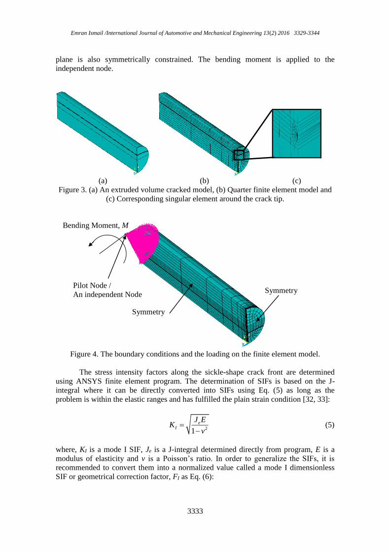
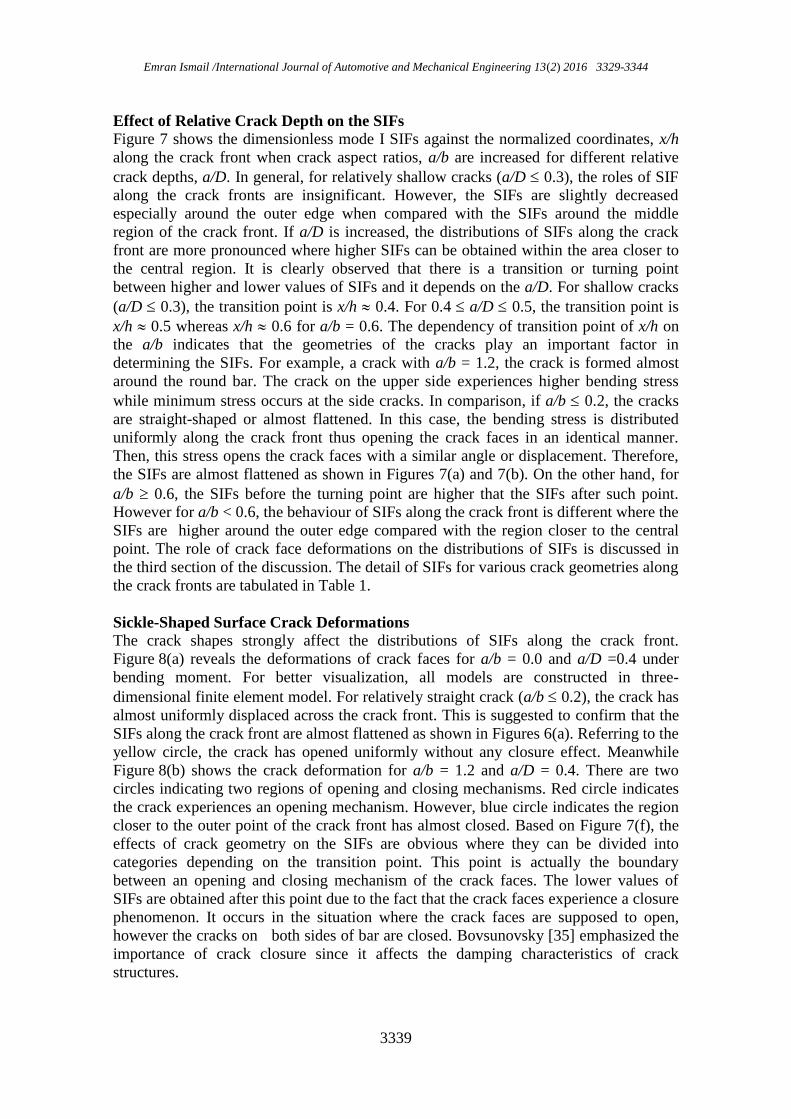
plane is also symmetrically constrained. The bending moment is applied to the
independent node.
(a) (b) (c)
Figure 3. (a) An extruded volume cracked model, (b) Quarter finite element model and
(c) Corresponding singular element around the crack tip.
Figure 4. The boundary conditions and the loading on the finite element model.
The stress intensity factors along the sickle-shape crack front are determined
using ANSYS finite element program. The determination of SIFs is based on the J-
integral where it can be directly converted into SIFs using Eq. (5) as long as the
problem is within the elastic ranges and has fulfilled the plain strain condition [32, 33]:
21
eI
J EK
v (5)
where, KI is a mode I SIF, Je is a J-integral determined directly from program, E is a
modulus of elasticity and v is a Poisson’s ratio. In order to generalize the SIFs, it is
recommended to convert them into a normalized value called a mode I dimensionless
SIF or geometrical correction factor, FI as Eq. (6):
Bending Moment, M
Symmetry
Symmetry Pilot Node /
An independent Node

Mode I stress intensity factors of sickle-shaped surface cracks in round solid bars under bending moment
3334
II
KF
a (6)
where, is an applied stress and a is a crack depth. Before the model is used further, it
is compulsory to validate that the present model is in the right condition. According to
Figure 5, it is revealed that the present model is well agreed with the existing model.
Therefore, this present model can be utilized for the further analysis.
Figure 5. Model validations of the present and the existing models.
RESULTS AND DISCUSSION
Effect of Crack Aspect Ratios on the SIFs
Figure 6 presents mode I normalized SIFs or geometrical correction factor, FI,b against
the normalized coordinate along the crack front when the relative crack depth, a/D is
increased for different crack aspect ratios, a/b. It is also revealed that for a/D 0.3, the
SIFs have no significant difference when a/D is varied since the shapes of crack fronts
are almost flattened or straight. Similar results can be found in [9-12] and therefore it
can be called as shallow cracks. When a/D > 0.3, the effect of a/D on the SIFs is
tremendous. This behaviour is observed for all crack aspect ratios. Referring to Figure
6, the patterns are SIFs which can also be categorized according to the ratio of a/b. For
a/b 0.2, the SIFs are almost flattened along crack front, however, the SIFs closer to
the outer point are slightly higher than others. This indicates that for straight or almost
straight crack front, the crack is probably initiated around those regions [9]. Toribio,
Matos [13] and Yang, Kuang [34] revealed that crack aspect ratios play an important
role in determining the shape of crack front, however it depend on the type of loading.
However, when a/b > 0.2, most of the SIFs located around the outer points start to
decrease when compared with the SIFs closer to the central point. This behaviour is due
to the fact that when the crack aspect ratio increases, the cracks appear circumferentially
around the solid bar [7-11]. It is difficult for the circumferential cracks to experience
mode I opening mechanism and therefore this reduces the SIFs. The effect of SIF
reductions is more significant if higher ratio of a/b is implemented. It is also observed

Emran Ismail /International Journal of Automotive and Mechanical Engineering 13(2) 2016 3329-3344
3335
that for a/b 0.8, the SIFs closer to the outer surface are almost similar indicating that
the cracks are not fully opened since the cracks are located at the sides of the round bar.
Figure 6 Continued …
(a)
(b)
(c)

Mode I stress intensity factors of sickle-shaped surface cracks in round solid bars under bending moment
3336
Figure 6. The effect of a/D on the mode I SIFs along the crack front for difference, a/b
(a) 0.0, (b) 0.2, (c) 0.4, (d) 0.6, (e) 0.8, (f) 1.
(d)
(e)
(f)

Emran Ismail /International Journal of Automotive and Mechanical Engineering 13(2) 2016 3329-3344
3337
Figure 7 Continued…
(c)
(a)
(b)

Mode I stress intensity factors of sickle-shaped surface cracks in round solid bars under bending moment
3338
Figure 7. The effect of a/D on the mode I SIFs along the crack front for difference a/b,
(a) 0.1, (b) 0.2, (c) 0.3, (d) 0.4, (e) 0.5 and (f) 0.6.
(d)
(e)
(f)
Emran Ismail /International Journal of Automotive and Mechanical Engineering 13(2) 2016 3329-3344
3339
Effect of Relative Crack Depth on the SIFs
Figure 7 shows the dimensionless mode I SIFs against the normalized coordinates, x/h
along the crack front when crack aspect ratios, a/b are increased for different relative
crack depths, a/D. In general, for relatively shallow cracks (a/D 0.3), the roles of SIF
along the crack fronts are insignificant. However, the SIFs are slightly decreased
especially around the outer edge when compared with the SIFs around the middle
region of the crack front. If a/D is increased, the distributions of SIFs along the crack
front are more pronounced where higher SIFs can be obtained within the area closer to
the central region. It is clearly observed that there is a transition or turning point
between higher and lower values of SIFs and it depends on the a/D. For shallow cracks
(a/D 0.3), the transition point is x/h 0.4. For 0.4 a/D 0.5, the transition point is
x/h 0.5 whereas x/h 0.6 for a/b = 0.6. The dependency of transition point of x/h on
the a/b indicates that the geometries of the cracks play an important factor in
determining the SIFs. For example, a crack with a/b = 1.2, the crack is formed almost
around the round bar. The crack on the upper side experiences higher bending stress
while minimum stress occurs at the side cracks. In comparison, if a/b 0.2, the cracks
are straight-shaped or almost flattened. In this case, the bending stress is distributed
uniformly along the crack front thus opening the crack faces in an identical manner.
Then, this stress opens the crack faces with a similar angle or displacement. Therefore,
the SIFs are almost flattened as shown in Figures 7(a) and 7(b). On the other hand, for
a/b 0.6, the SIFs before the turning point are higher that the SIFs after such point.
However for a/b < 0.6, the behaviour of SIFs along the crack front is different where the
SIFs are higher around the outer edge compared with the region closer to the central
point. The role of crack face deformations on the distributions of SIFs is discussed in
the third section of the discussion. The detail of SIFs for various crack geometries along
the crack fronts are tabulated in Table 1.
Sickle-Shaped Surface Crack Deformations The crack shapes strongly affect the distributions of SIFs along the crack front.
Figure 8(a) reveals the deformations of crack faces for a/b = 0.0 and a/D =0.4 under
bending moment. For better visualization, all models are constructed in three-
dimensional finite element model. For relatively straight crack (a/b 0.2), the crack has
almost uniformly displaced across the crack front. This is suggested to confirm that the
SIFs along the crack front are almost flattened as shown in Figures 6(a). Referring to the
yellow circle, the crack has opened uniformly without any closure effect. Meanwhile
Figure 8(b) shows the crack deformation for a/b = 1.2 and a/D = 0.4. There are two
circles indicating two regions of opening and closing mechanisms. Red circle indicates
the crack experiences an opening mechanism. However, blue circle indicates the region
closer to the outer point of the crack front has almost closed. Based on Figure 7(f), the
effects of crack geometry on the SIFs are obvious where they can be divided into
categories depending on the transition point. This point is actually the boundary
between an opening and closing mechanism of the crack faces. The lower values of
SIFs are obtained after this point due to the fact that the crack faces experience a closure
phenomenon. It occurs in the situation where the crack faces are supposed to open,
however the cracks on both sides of bar are closed. Bovsunovsky [35] emphasized the
importance of crack closure since it affects the damping characteristics of crack
structures.

Mode I stress intensity factors of sickle-shaped surface cracks in round solid bars under bending moment
3340
(a)
(b)
Figure 8 Crack deformations under bending moment, (a) a/b = 0.0 and a/D = 0.4 and (b)
a/b = 1.2 and a/D = 0.4.
Stress Intensity Factors at the x/h = 0.0
Figure 8 shows the variation of stress intensity factors at the middle point along the
crack front (x/h = 0.0) for different a/b. These SIFs are also the maximum value
compared with other SIFs of identical crack front. In general, higher SIFs are obtained
when a/b ratios increase. For the relatively shallow cracks, in this case a/D 0.2, the
effects of geometries on the SIFs are insignificant where the stress intensity factors are
almost identical. Similar works can be found in [10-13] where the stress intensity
factors along the crack front for crack geometries of a/D 0.2 do not have much
difference. However when deeper cracks are used, the role of a/b become of paramount
importance. Figure 8 also reveals that when higher a/b is used, the maximum SIFs occur
at the middle point along the crack front. It indicates that under bending moment, the
crack relatively starts to initiate firstly at the mid-point before going to other locations.
For the case of a/b 0.2 (straight and almost straight-fronted cracks), the SIFs for a/D
0.4 are relatively flattened. This is to show that the cracks grow along the crack front are
almost uniformed where the tendency of the crack to initiate probably is in a similar
manner. However when the a/D 0.5, different SIFs behaviour is observed, where the
SIFs at x/h = 0.0 are gradually increased. This is due to the fact that when a/b increases,
the ligament cross-sectional area becomes smaller thus increasing the bending stress [9]
and therefore increasing the stress intensity factors.

Emran Ismail /International Journal of Automotive and Mechanical Engineering 13(2) 2016 3329-3344
3341
Table 1. List of SIFs of sickle-shaped crack under bending moments.
x/h a/D a/b
0.0 0.2 0.4 0.6 0.8 1.0 1.2
0.00
0.1 0.8764 0.8440 0.8722 0.8861 0.9143 0.9499 0.9966
0.2 0.8270 0.8111 0.8282 0.8754 0.9153 0.9681 1.0497
0.3 0.8485 0.8422 0.8725 0.9333 1.0026 1.0956 1.2048
0.4 0.9403 0.9545 1.0048 1.0863 1.2035 1.3448 1.4972
0.5 1.1364 1.1466 1.2617 1.3977 1.5935 1.8123 2.0353
0.6 1.5107 1.5560 1.7312 2.0395 2.3831 2.7430 3.0993
0.17
0.1 0.8819 0.8515 0.8855 0.8898 0.9150 0.9472 0.9819
0.2 0.8319 0.8161 0.8309 0.8768 0.9125 0.9570 1.0223
0.3 0.8529 0.8459 0.8726 0.9327 0.9958 1.0759 1.1633
0.4 0.9457 0.9576 1.0067 1.0828 1.1898 1.3126 1.4359
0.5 1.1419 1.1494 1.2556 1.3890 1.5684 1.7596 1.9412
0.6 1.5151 1.5606 1.7269 2.0197 2.3356 2.6511 2.9432
0.33
0.1 0.8928 0.8658 0.8889 0.8945 0.9113 0.9316 0.9263
0.2 0.8451 0.8284 0.8371 0.8765 0.8980 0.9151 0.9270
0.3 0.8643 0.8556 0.8733 0.9262 0.9663 1.0046 1.0242
0.4 0.9598 0.9661 1.0086 1.0659 1.1377 1.2005 1.2348
0.5 1.1569 1.1571 1.2415 1.3530 1.4767 1.5781 1.6361
0.6 1.5282 1.5690 1.7069 1.9426 2.1629 2.3334 2.4367
0.50
0.1 0.9162 0.8797 0.9003 0.9040 0.9070 0.9070 0.8381
0.2 0.8702 0.8487 0.8508 0.8780 0.8729 0.8447 0.7783
0.3 0.8863 0.8783 0.8864 0.9157 0.9156 0.8859 0.8118
0.4 0.9869 0.9890 1.0134 1.0360 1.0471 1.0146 0.9329
0.5 1.1853 1.1789 1.2364 1.2884 1.3166 1.2802 1.1840
0.6 1.5557 1.5826 1.6731 1.8038 1.8620 1.8178 1.6948
0.67
0.1 0.9589 0.9138 0.9317 0.9247 0.9037 0.8736 0.7209
0.2 0.9179 0.8896 0.8835 0.8870 0.8399 0.7460 0.5889
0.3 0.9277 0.9247 0.9209 0.9039 0.8411 0.7197 0.5498
0.4 1.0378 1.0366 1.0261 0.9915 0.9108 0.7588 0.5699
0.5 1.2358 1.2248 1.2432 1.1854 1.0752 0.8776 0.6536
0.6 1.6046 1.6046 1.6182 1.5808 1.4143 1.1340 0.8424
0.83
0.1 1.0463 1.0252 1.0303 0.9754 0.9162 0.8417 0.5851
0.2 1.0284 0.9959 0.9723 0.9234 0.8068 0.6217 0.3750
0.3 1.0240 1.0371 1.0056 0.9054 0.7400 0.5050 0.2703
0.4 1.1543 1.1475 1.0677 0.9298 0.7115 0.4405 0.2155
0.5 1.3404 1.3253 1.2509 1.0199 0.7291 0.4095 0.2280
0.6 1.6921 1.6449 1.5162 1.2219 0.8028 0.4318 0.4204

Mode I stress intensity factors of sickle-shaped surface cracks in round solid bars under bending moment
3342
Figure 8 The SIFs for different a/b at the x/h = 0.0.
CONCLUSIONS
In this paper, the behaviour of sickle-shaped surface cracks in round bars are
investigated and analysed where it is subjected to remote bending moment. The stress
intensity factors (SIF) are based on the J-integral. Then the normalized SIFs are plotted
against the normalized locations along the crack front. Seven crack aspect ratios, a/b
and six relative crack depths, a/D are modelled using ANSYS finite element program.
According to the numerical simulations, it is found that:
i). For the shallow cracks (a/D 0.3), the SIFs have no significant difference even
though different a/b are used.
ii). For straight or relatively straight cracks (a/b 0.2), the distributions of SIFs along
the crack fronts are almost flattened. However when a/b > 0.2 are used, the SIFs
around the outer surfaces are relatively lower that the SIFs closer to the central
regions.
iii). From numerical simulations, it is observed that the circumferential side cracks
experience insignificant mode I opening mechanisms compared with the cracks
located at the upper side.
ACKNOWLEDGEMENTS
Author acknowledges Universiti Tun Hussein Onn Malaysia for supporting this work.
REFERENCES
[1] Ali N, Mustapa M, Ghazali M, Sujitno T, Ridha M. Fatigue life prediction of
commercially pure titanium after nitrogen ion implantation. International Journal
of Automotive and Mechanical Engineering. 2013;7:1005.
[2] Daud R, Ariffin A, Abdullah S. Validation of crack interaction limit model for
parallel edge cracks using two-dimensional finite element analysis. International
Journal of Automotive and Mechanical Engineering. 2013;7:993.

Emran Ismail /International Journal of Automotive and Mechanical Engineering 13(2) 2016 3329-3344
3343
[3] Kamal M, Rahman MM. Finite Element-Based Fatigue Behaviour of Springs in
Automobile Suspension. International Journal of Automotive and Mechanical
Engineering. 2014;10:1910.
[4] Wor L, Rahman MM. Stress behavior of tailor-welded blanks for dissimilar
metals using finite element method. International Journal of Automotive and
Mechanical Engineering. 2015;11:2541.
[5] Ismail AE, Aziz MCA. Tensile strength of woven yarn kenaf fiber reinforced
polyester composites. 2015.
[6] Siswanto WA, Nagentrau M, Tobi M, Latif A. Prediction of residual stress using
explicit finite element method. Journal of Mechanical Engineering and Sciences.
2015;9:1556-70.
[7] Ismail AE, Ariffin A, Abdullah S, Ghazali M. Off-set crack propagation analysis
under mixed mode loadings. International Journal of Automotive Technology.
2011;12:225-32.
[8] Ismail AE, Ariffin A, Abdullah S, Ghazali M. Stress intensity factors for surface
cracks in round bar under single and combined loadings. Meccanica.
2012;47:1141-56.
[9] Toribio J, Álvarez N, González B, Matos J. A critical review of stress intensity
factor solutions for surface cracks in round bars subjected to tension loading.
Engineering Failure Analysis. 2009;16:794-809.
[10] Carpinteri A, Vantadori S. Sickle-shaped cracks in metallic round bars under
cyclic eccentric axial loading. International Journal of Fatigue. 2009;31:759-65.
[11] Mattheck C, Morawietz P, Munz D. Stress intensity factors of sickle-shaped
cracks in cylindrical bars. International Journal of Fatigue. 1985;7:45-7.
[12] Hobbs J, Burguete R, Heyes P, Patterson E. A photoelastic analysis of crescent-
shaped cracks in bolts. The Journal of Strain Analysis for Engineering Design.
2001;36:93-100.
[13] Toribio J, Matos J-C, González B, Escuadra J. Fatigue crack growth in round
bars for rock anchorages: the role of residual stresses. Procedia Structural
Integrity. 2016;2:2734-41.
[14] Śnieżek L, Ślęzak T, Grzelak K, Hutsaylyuk V. An experimental investigation
of propagation the semi-elliptical surface cracks in an austenitic steel.
International Journal of Pressure Vessels and Piping. 2016;144:35-44.
[15] Coules H. Stress intensity interaction between dissimilar semi-elliptical surface
cracks. International Journal of Pressure Vessels and Piping. 2016;146:55-64.
[16] Weißgraeber P, Felger J, Geipel D, Becker W. Cracks at elliptical holes: stress
intensity factor and finite fracture mechanics solution. European Journal of
Mechanics-A/Solids. 2016;55:192-8.
[17] Zerbst U, Vormwald M, Pippan R, Gänser H-P, Sarrazin-Baudoux C, Madia M.
About the fatigue crack propagation threshold of metals as a design criterion–a
review. Engineering Fracture Mechanics. 2016;153:190-243.
[18] Kamal M, Rahman MM. An Integrated Approach for fatigue life estimation
based on continuum mechanics theory and genetic algorithm. International
Journal of Automotive and Mechanical Engineering. 2015;11:2756-70.
[19] Kamal M, Rahman MM. Fatigue life estimation based on continuum mechanics
theory with application of genetic algorithm. International Journal of
Automotive and Mechanical Engineering. 2015;11:2686-98.

Mode I stress intensity factors of sickle-shaped surface cracks in round solid bars under bending moment
3344
[20] Yunoh MFM, Abdullah S, Saad MHM, Nopiah ZM, Nuawi MZ. Fatigue feature
extraction analysis based on a K-means clustering approach. Journal of
Mechanical Engineering and Sciences. 2015;8:1275-82.
[21] Ahmad MIM, Arifin A, Abdullah S. Evaluation of magnetic flux leakage signals
on fatigue crack growth of mild steel. Journal of Mechanical Engineering and
Sciences. 2015;9:1727-33.
[22] Abdul Majid MS, Daud R, Afendi M, Amin NAM, Cheng EM, Gibson AG, et
al. Stress-Strain response modelling of glass fibre reinforced epoxy composite
pipes under multiaxial loadings. Journal of Mechanical Engineering and
Sciences. 2014;6:916-28.
[23] Kamal M, Rahman MM. Dual-Criteria method for determining critical plane
orientation for multiaxial fatigue prediction using a genetic algorithm.
International Journal of Automotive and Mechanical Engineering.
2015;11:2571-81.
[24] Kamal M, Rahman MM. Finite element-based fatigue behaviour of springs in
automobile suspension. International Journal of Automotive and Mechanical
Engineering. 2014;10:1910-9.
[25] Daud R, Ariffin AK, Abdullah S. Validation of Crack Interaction Limit Model
for Parallel Edge Cracks using Two-Dimensional Finite Element Analysis.
International Journal of Automotive and Mechanical Engineering. 2013;7:993-
1004.
[26] Predan J, Močilnik V, Gubeljak N. Stress intensity factors for circumferential
semi-elliptical surface cracks in a hollow cylinder subjected to pure torsion.
Engineering Fracture Mechanics. 2013;105:152-68.
[27] Carpinteri A, Brighenti R, Vantadori S, Viappiani D. Sickle‐shaped crack in a
round bar under complex Mode I loading. Fatigue & Fracture of Engineering
Materials & Structures. 2007;30:524-34.
[28] Carpinteri A, Vantadori S. Sickle‐shaped surface crack in a notched round bar
under cyclic tension and bending. Fatigue & Fracture of Engineering Materials
& Structures. 2009;32:223-32.
[29] Ismail A, Ariffin A, Abdullah S, Ghazali M. Stress intensity factors under
combined tension and torsion loadings. Indian Journal of Engineering &
Materials Sciences. 2012;19:5-16.
[30] Ariffin AK, Abdullah S, Ghazali MJ, Abdulrazzaq M, Daud R. Stress intensity
factors under combined bending and torsion moments. Journal of Zhejiang
University Science A. 2012;13:1-8.
[31] Rice JR. A path independent integral and the approximate analysis of strain
concentration by notches and cracks. Journal of Applied Mechanics.
1968;35:379-86.
[32] Parks D. The virtual crack extension method for nonlinear material behavior.
Computer Methods in Applied Mechanics and Engineering. 1977;12:353-64.
[33] Rahman S. Probabilistic fracture mechanics: J-estimation and finite element
methods. Engineering Fracture Mechanics. 2001;68:107-25.
[34] Yang F, Kuang Z, Shlyannikov V. Fatigue crack growth for straight-fronted
edge crack in a round bar. International Journal of Fatigue. 2006;28:431-7.
[35] Bovsunovsky A. Energy dissipation in the non-propagating surface cracks in
steel round bar at torsional vibration. Engineering Fracture Mechanics.
2012;92:32-9.