MODBUS TCP Master Driver - hmisource.com · MODBUS TCP Master Driver GP-Pro EX Device/PLC...
44
1 Schneider Electric SA MODBUS TCP Master Driver 1 System Configuration ....................................................................................................... 3 2 External Devices Selection .............................................................................................. 7 3 Communication Settings .................................................................................................. 8 4 Setup Items .................................................................................................................... 22 5 Supported Devices ......................................................................................................... 28 6 Device Code and Address Code .................................................................................... 42 7 Error Messages .............................................................................................................. 43
Transcript of MODBUS TCP Master Driver - hmisource.com · MODBUS TCP Master Driver GP-Pro EX Device/PLC...
1
Schneider Electric SA
MODBUS TCP Master Driver
1 System Configuration....................................................................................................... 3
2 External Devices Selection .............................................................................................. 7
3 Communication Settings .................................................................................................. 8
4 Setup Items .................................................................................................................... 22
5 Supported Devices......................................................................................................... 28
6 Device Code and Address Code.................................................................................... 42
7 Error Messages.............................................................................................................. 43

MODBUS TCP Master Driver
GP-Pro EX Device/PLC Connection Manual 2
Introduction
This manual describes how to connect the Display and the External Device (target PLC).
In this manual, the connection procedure is described in the sections identified below:
1 System Configuration
This section lists the types of External
Devices and SIO that you can connect.
"1 System Configuration" (page 3)
2 External Devices Selection
Select the model (series) of the External
Device and its connection method.
"2 External Devices Selection" (page 7)
3 Communication Settings
This section shows setting examples for
communicating between the Display and
the External Device.
"3 Communication Settings" (page 8)
4 Setup Items
This section describes communication
setup items on the Display.
Set the Display's communication settings
in GP Pro-EX or in offline mode.
"4 Setup Items" (page 22)
Operation
MODBUS TCP Master Driver
GP-Pro EX Device/PLC Connection Manual 3
1 System Configuration
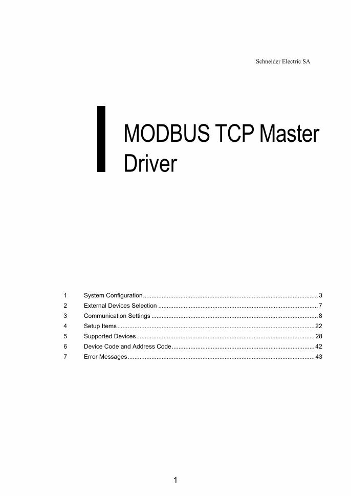
The system configuration in the case when the External Device and the Display are connected is shown.
1.1 Schneider Electric SA External Device
Driver CPU Link I/F SIO TypeSetting
Example
Premium
TSX P57 103MTSX P57 153MTSX P57 203MTSX P57 253MTSX P57 303MTSX P57 353MTSX P57 453M
TSX ETY 4102TSX ETY 4103TSX ETY 5102TSX ETY 5103TSX WMY 100 M
Ethernet(Modbus TCP)
Setting Example 1 (page 8)
TSX P57 2623MTSX P57 2823MTSX P57 3623MTSX P57 4823M
------Setting Example 2 (page 10)
Quantum
140 CPU 113 02140 CPU 113 03140 CPU 434 12A140 CPU 534 14A
140 NOE 771 00140 NOE 771 10140 NWM 100 00
Setting Example 3 (page 12)
140 CPU 651 50140 CPU 651 60
------Setting Example 4 (page 14)
M221
TM221CE16RTM221CE16TTM221CE16UTM221CE24RTM221CE24TTM221CE24UTM221CE40RTM221CE40TTM221CE40U
------
Ethernet(SoMachine Basic Syntax)
Setting Example 6 (page 19)
TM221ME16RTM221ME16RGTM221ME16TTM221ME16TGTM221ME32TK
------

MODBUS TCP Master Driver
GP-Pro EX Device/PLC Connection Manual 4
Connection Configuration
• 1:1 Connection
• 1:n Connection
• n:1 Connection (Premium Series)
Maximum number of Display are 4.
*1 You can connect max 1 unit of TSXP571**/TSXP572**, max 3 units of TSXP573**, max 4 units of TSXP574**.
*2 Number of connecting units is the unit number when connecting the Display only. Number of connecting Display will be limited by the number of other External Devices which is connected by Ethernet.

MODBUS TCP Master Driver
GP-Pro EX Device/PLC Connection Manual 5
• n:1 Connection (Quantum Series)
Maximum number of Display are 32.
*3 Number of connecting units is the unit number when connecting the Display only. Number of connecting Display will be limited by the number of other External Devices which is connected by Ethernet.
• n:1 Connection (M221 Series)
Maximum number of Display are 8.
*4 Number of connecting units is the unit number when connecting the Display only. Number of connecting Display will be limited by the number of other External Devices which is connected by Ethernet.
*4
MODBUS TCP Master Driver
GP-Pro EX Device/PLC Connection Manual 6
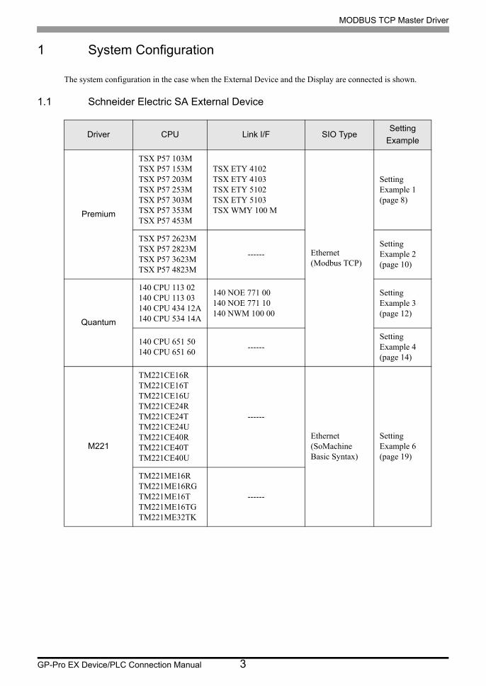
1.2 YOKOGAWA Electric Corporation External Device
Connection Configuration
• 1:1 Connection
• 1:n Connection
• n:1 Connection
*1 Number of connecting units is the unit number when connecting the Display only. Number of connecting Display will be limited by the number of other External Devices which is connected by Ethernet.
Driver CPU Link I/F SIO TypeSetting
Example
FCN NFCP100-S00Network interface on
CPUEthernet(Modbus TCP)
Setting Example 5 (page 16)
FCJ NFJT100-S100Control network interface on the
controller
Setting Example 5 (page 16)

MODBUS TCP Master Driver
GP-Pro EX Device/PLC Connection Manual 7
2 External Devices Selection
Select the External Device to be connected to the Display.
Setup Items Setup Description
Number of Devices/PLCs
Enter an integer from 1 to 4 to define the number of Devices/PLCs to connect to the display.
Manufacturer Select the manufacturer of the External Device to connect. Select "Schneider Electric SA".
Series
Select the External Device model (series) and the connection method. Select "MODBUS TCP Master".In System configuration, make sure the External Device you are connecting is supported by "MODBUS TCP Master".
"1 System Configuration" (page 3)
Port Select the Display port to connect to the External Device.
Use System Area
Check this option to synchronize the system data area of the Display and the device (memory) of the External Device. When synchronized, you can use the External Device’s ladder program to switch the display or display the window on the Display.
Cf. GP-Pro EX Reference Manual "LS Area (Direct Access Method Area)"This feature can also be set in GP-Pro EX or in the Display's offline mode.
Cf. GP-Pro EX Reference Manual "System Settings [Display Unit] - [System Area] Settings Guide"
Cf. Maintenance/Troubleshooting Guide "Main Unit - System Area Settings"
MODBUS TCP Master Driver
GP-Pro EX Device/PLC Connection Manual 8
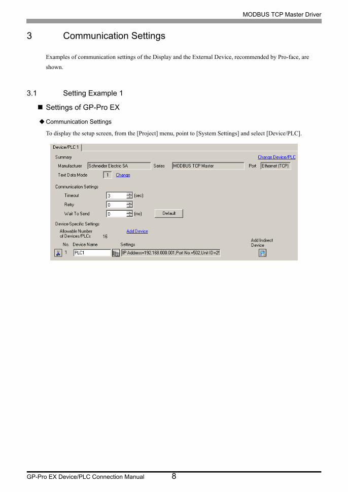
3 Communication Settings
Examples of communication settings of the Display and the External Device, recommended by Pro-face, are
shown.
3.1 Setting Example 1
Settings of GP-Pro EX
Communication Settings
To display the setup screen, from the [Project] menu, point to [System Settings] and select [Device/PLC].

MODBUS TCP Master Driver
GP-Pro EX Device/PLC Connection Manual 9
Device Setting
To display the [Individual Device Settings] dialog box, from [Device-Specific Settings] in the [Device/PLC]
window, select the external device and click [Settings] .
To connect multiple External Devices, from [Device-Specific Settings] in the [Device/PLC] window, click [Add
Device] to add another External Device.
Notes
• Check with the network administrator about the IP address. Do not duplicate IP addresses.
• Set IP address on the External Device for IP address in Device-specific settings.
• You need to set the IP address of the Display in its offline mode.
External Device Settings
Use the ladder software "PL7 PRO" for communication settings.
Execute "Hardware Configuration" from "Configuration" in "Application Browser" of "PL7 PRO" to display the
"Configuration" dialog box. Double-click the empty slot to display the "Add Module" dialog box. Select
"Communication" in the "Family" field. Then select "Link Unit" display in the "Module" field to display the
screen for setting.
Notes
• Check with the network administrator about the IP address. Do not duplicate IP addresses.
• Please refer to the manual of the ladder software for details on other settings.
Setup Items Setup Description
IP address configuration Configured (Fixed)
IP address Optional
Ethernet configuration Ethernet II (Fixed)
[Equipment Configuration]Tab [Max Query] tab
MODBUS TCP Master Driver
GP-Pro EX Device/PLC Connection Manual 10
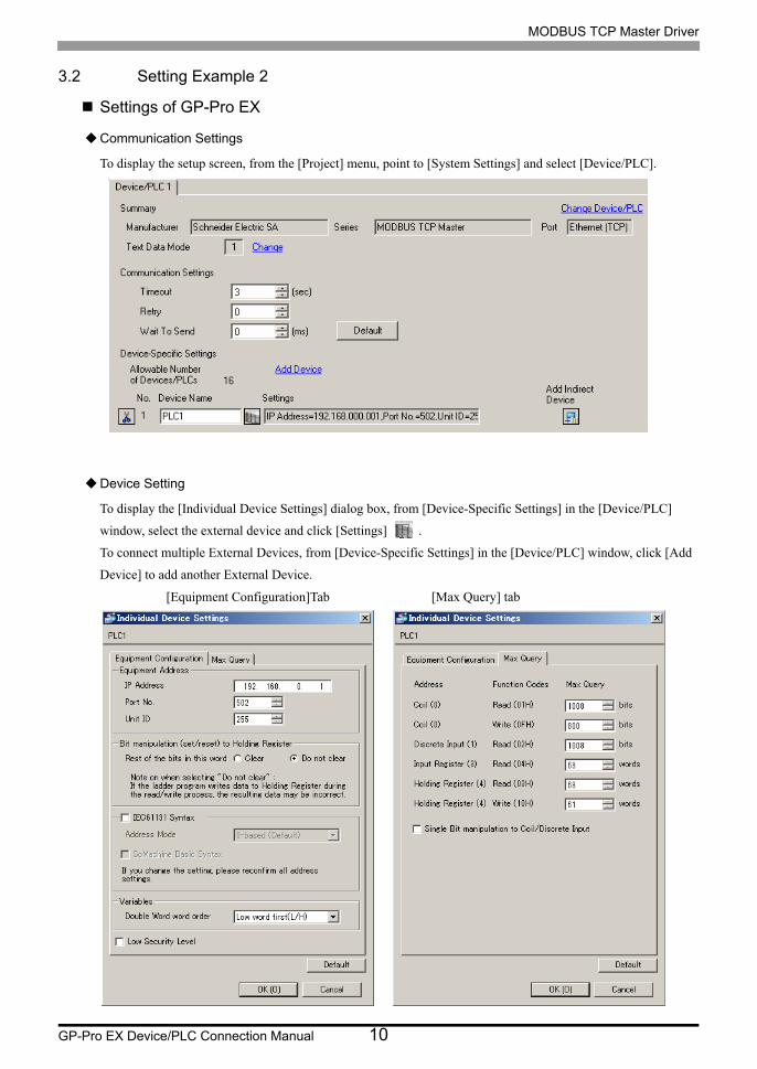
3.2 Setting Example 2
Settings of GP-Pro EX
Communication Settings
To display the setup screen, from the [Project] menu, point to [System Settings] and select [Device/PLC].
Device Setting
To display the [Individual Device Settings] dialog box, from [Device-Specific Settings] in the [Device/PLC]
window, select the external device and click [Settings] .
To connect multiple External Devices, from [Device-Specific Settings] in the [Device/PLC] window, click [Add
Device] to add another External Device.
[Equipment Configuration]Tab [Max Query] tab

MODBUS TCP Master Driver
GP-Pro EX Device/PLC Connection Manual 11
Notes
• Check with the network administrator about the IP address. Do not duplicate IP addresses.
• Set the IP address of the External Device under [Individual Device Settings].
• You need to set the IP address of the Display in its offline mode.
External Device Settings
Use the ladder software "PL7 PRO" for communication settings.
For setting, go to "Configuration" in "Application Browser" of "PL7 PRO", "Hardware Configuration", and "ETY
PORT" in this order.
Notes
• Check with the network administrator about the IP address. Do not duplicate IP addresses.
• Please refer to the manual of the ladder software for details on other settings.
Setup Items Setup Description
IP address configuration Configured (Fixed)
IP address Optional
Ethernet configuration Ethernet II (Fixed)

MODBUS TCP Master Driver
GP-Pro EX Device/PLC Connection Manual 12
3.3 Setting Example 3
Settings of GP-Pro EX
Communication Settings
To display the setup screen, from the [Project] menu, point to [System Settings] and select [Device/PLC]..
Device Setting
To display the [Individual Device Settings] dialog box, from [Device-Specific Settings] in the [Device/PLC]
window, select the external device and click [Settings] .
To connect multiple External Devices, from [Device-Specific Settings] in the [Device/PLC] window, click [Add
Device] to add another External Device.
[Equipment Configuration] tab [Max Query] tab

MODBUS TCP Master Driver
GP-Pro EX Device/PLC Connection Manual 13
Notes
• Check with the network administrator about the IP address. Do not duplicate IP addresses.
• Set the IP address of the External Device under [Individual Device Settings].
• You need to set the IP address of the Display in its offline mode.
External Device Settings
Use the ladder software "Concept" for communication settings.
After selecting PLC for the Quantum Series in "PLC Selection" of "Concept", select "Select Extensions" from
"Config Extension". Set the number of Link Unit connected to "TCP/IP Ethernet" in the "Select Extensions"
dialog box displayed next. Then, select "Ethernet /I/O Scanner" in "Config Extensions" and perform setting in the
"Ethernet /I/O Scanner" dialog box.
Notes
• Check with the network administrator about the IP address. Do not duplicate IP addresses.
• Please refer to the manual of the ladder software for details on other settings.
Setup Items Setup Description
Ethernet configuration Specify IP Address (Fixed)
Internet Address Optional
Frame Type Ethernet II (Fixed)

MODBUS TCP Master Driver
GP-Pro EX Device/PLC Connection Manual 14
3.4 Setting Example 4
Settings of GP-Pro EX
Communication Settings
To display the setup screen, from the [Project] menu, point to [System Settings] and select [Device/PLC].
Device Setting
To display the [Individual Device Settings] dialog box, from [Device-Specific Settings] in the [Device/PLC]
window, select the external device and click [Settings] .
To connect multiple External Devices, from [Device-Specific Settings] in the [Device/PLC] window, click [Add
Device] to add another External Device.
[Equipment Configuration] tab [Max Query] tab

MODBUS TCP Master Driver
GP-Pro EX Device/PLC Connection Manual 15
Notes
• Check with the network administrator about the IP address. Do not duplicate IP addresses.
• Set the IP address of the External Device under [Individual Device Settings].
• You need to set the IP address of the Display in its offline mode.
External Device Settings
Use the ladder software "Unity Pro XL" for communication settings.
Startup "Unity Pro XL". Select "New Project" and specify CPU (Quantum Series, 140 CPU 651 *0). Go to
"Communication" in "Project Browser", and right-click on "Network" to select "New Network...". Then the Add
Network window is displayed.
Set "List of available Networks" in the "Add Network" window to "Ethernet". Put the optional name in "Change
Name" and press OK.
Check that the name you put in "Change Name" is displayed under "Network", "Communication" of "Project
Browser". Double-click the displayed name to display the "(Your optional name) window" for setting.
Notes
• Check with the network administrator about the IP address. Do not duplicate IP addresses.
• Please refer to the manual of the ladder software for details on other settings.
Setup Items Setup Description
IP address configuration Configured (Fixed)
IP address Optional
Ethernet configuration Ethernet II (Fixed)

MODBUS TCP Master Driver
GP-Pro EX Device/PLC Connection Manual 16
3.5 Setting Example 5
Settings of GP-Pro EX
Communication Settings
To display the setup screen, from the [Project] menu, point to [System Settings] and select [Device/PLC]..
Device Setting
To display the [Individual Device Settings] dialog box, from [Device-Specific Settings] in the [Device/PLC]
window, select the external device and click [Settings] .
To connect multiple External Devices, from [Device-Specific Settings] in the [Device/PLC] window, click [Add
Device] to add another External Device.
[Equipment Configuration] tab [Max Query] tab

MODBUS TCP Master Driver
GP-Pro EX Device/PLC Connection Manual 17
Notes
• Check with the network administrator about the IP address. Do not duplicate IP addresses.
• Set the IP address of the External Device under [Individual Device Settings].
• You need to set the IP address of the Display in its offline mode.
External Device Settings
Use the ladder software (Logic Designer) for communication settings. Refer to your External Device manual for
details.
1 Start up the ladder software.
2 To start the MODBUS communication (RTU mode) slave function, create the control logic. For the example of
control logic, refer to "Control Logic Example".
Control Logic Example (page 17)
3 Select [Rebuild Project] from the [Build] menu.
4 Double-click [Target Setting] in the project tree Window to display the [Target] dialog box.
5 Enter "192.168.0.1" in [Host Name/IP Address].
6 Click [OK].
7 Download the communication settings to the External Device.
8 Reboot the External Device.
Control Logic Example
To connect the Display to the External Device, the control logic is required.
The control logic example is shown below.
SD_CMDBSE_BS_OPENSD_CMDBSE_BS_OPEN
TRUE REQ VALID TCP_VALID
UNIT#5 TIMEOUT ERROR TCP_ERROR
UNIT#20 DELAY STATUS TCP_STARUS
' YOKOGAWA ' VENDOR
' STARDOM ' PRODUCT
' R1 . 80 . 01 ' REVISION
� OPTION
COIL COIL COIL COIL
DSCI DSCI DSCI DSCI
IREG IREG IREG IREG
HREG HREG HREG HREG
ESTS ESTS ESTS ESTS
TCP_COMERR COMERR COMERR TCP_COMERR

MODBUS TCP Master Driver
GP-Pro EX Device/PLC Connection Manual 18
Notes
• Check with the network administrator about the IP address. Do not duplicate IP addresses.
• Please refer to the manual of the ladder software for details on other settings.
MODBUS TCP Master Driver
GP-Pro EX Device/PLC Connection Manual 19
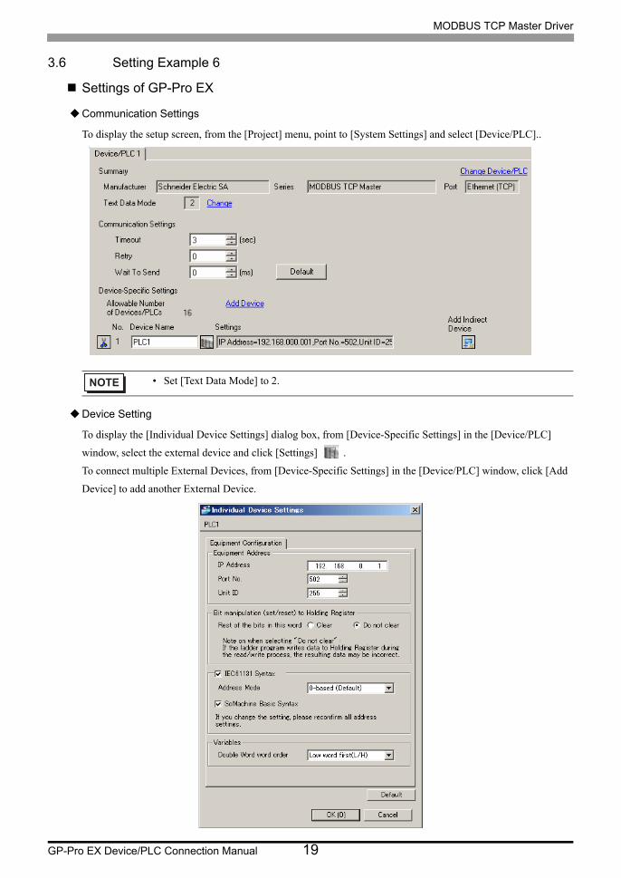
3.6 Setting Example 6
Settings of GP-Pro EX
Communication Settings
To display the setup screen, from the [Project] menu, point to [System Settings] and select [Device/PLC]..
Device Setting
To display the [Individual Device Settings] dialog box, from [Device-Specific Settings] in the [Device/PLC]
window, select the external device and click [Settings] .
To connect multiple External Devices, from [Device-Specific Settings] in the [Device/PLC] window, click [Add
Device] to add another External Device.
• Set [Text Data Mode] to 2.
MODBUS TCP Master Driver
GP-Pro EX Device/PLC Connection Manual 20
Notes
• Check with the network administrator about the IP address. Do not duplicate IP addresses.
• Set the IP address of the External Device under [Individual Device Settings].
• You need to set the IP address of the Display in its offline mode.
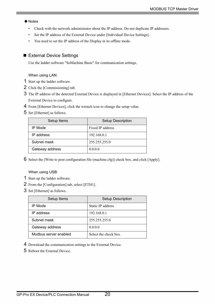
External Device Settings
Use the ladder software "SoMachine Basic" for communication settings.
When using LAN:
1 Start up the ladder software.
2 Click the [Commissioning] tab.
3 The IP address of the detected External Device is displayed in [Ethernet Devices]. Select the IP address of the
External Device to configure.
4 From [Ethernet Devices], click the wrench icon to change the setup value.
5 Set [Ethernet] as follows.
6 Select the [Write to post configuration file (machine.cfg)] check box, and click [Apply].
When using USB:
1 Start up the ladder software.
2 From the [Configuration] tab, select [ETH1].
3 Set [Ethernet] as follows.
4 Download the communication settings to the External Device.
5 Reboot the External Device.
Setup Items Setup Description
IP Mode Fixed IP address
IP address 192.168.0.1
Subnet mask 255.255.255.0
Gateway address 0.0.0.0
Setup Items Setup Description
IP Mode Static IP address
IP address 192.168.0.1
Subnet mask 255.255.255.0
Gateway address 0.0.0.0
Modbus server enabled Select the check box.
MODBUS TCP Master Driver
GP-Pro EX Device/PLC Connection Manual 21
Notes
• After configuring the External Device over LAN, set up is not possible over USB.
To use USB for set up, from the [Commissioning] tab, select [Erase in controller] from the [Memory
management] and delete the "machine.cfg" file.
• Check with the network administrator about the IP address. Do not duplicate IP addresses.
• Please refer to the manual of the ladder software for details on other settings.

MODBUS TCP Master Driver
GP-Pro EX Device/PLC Connection Manual 22
4 Setup Items
Set up the Display's communication settings in GP Pro-EX or in the Display's offline mode.
The setting of each parameter must match that of the External Device.
"3 Communication Settings" (page 8)
4.1 Setup Items in GP-Pro EX
Communication Settings
To display the setup screen, from the [Project] menu, point to [System Settings] and select [Device/PLC].
• You need to set the IP address of the Display in its offline mode.
Cf. Maintenance/Troubleshooting Guide "Ethernet Settings"
Setup Items Setup Description
TimeoutUse an integer from 1 to 127 to enter the time (s) for which the Display waits for the response from the External Device.
RetryIn case of no response from the External Device, use an integer from 0 to 255 to enter how many times the Display retransmits the command.
Wait To SendUse an integer from 0 to 255 to enter standby time (ms) for the Display from receiving packets to transmitting the next commands.
• Refer to the GP-Pro EX Reference Manual for Indirect Device.
Cf. GP-Pro EX Reference Manual "Changing the Device/PLC at Runtime (Indirect Device)"
MODBUS TCP Master Driver
GP-Pro EX Device/PLC Connection Manual 23
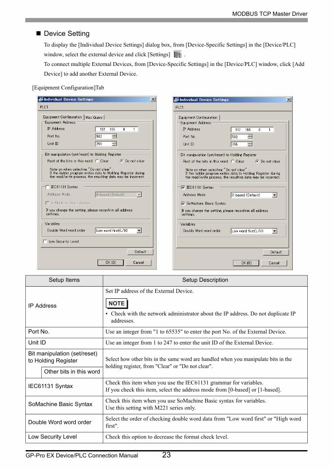
Device Setting
To display the [Individual Device Settings] dialog box, from [Device-Specific Settings] in the [Device/PLC]
window, select the external device and click [Settings] .
To connect multiple External Devices, from [Device-Specific Settings] in the [Device/PLC] window, click [Add
Device] to add another External Device.
Setup Items Setup Description
IP Address
Set IP address of the External Device.
• Check with the network administrator about the IP address. Do not duplicate IP addresses.
Port No. Use an integer from "1 to 65535" to enter the port No. of the External Device.
Unit ID Use an integer from 1 to 247 to enter the unit ID of the External Device.
Bit manipulation (set/reset) to Holding Register Select how other bits in the same word are handled when you manipulate bits in the
holding register, from "Clear" or "Do not clear".Other bits in this word
IEC61131 SyntaxCheck this item when you use the IEC61131 grammar for variables.If you check this item, select the address mode from [0-based] or [1-based].
SoMachine Basic SyntaxCheck this item when you use SoMachine Basic syntax for variables. Use this setting with M221 series only.
Double Word word orderSelect the order of checking double word data from "Low word first" or "High word first".
Low Security Level Check this option to decrease the format check level.
[Equipment Configuration]Tab

MODBUS TCP Master Driver
GP-Pro EX Device/PLC Connection Manual 24
Setup Items Setup Description
Coil Set the number of max data for device [coil] that can be read for one communication, using 16 to 2000 bits.
• If you check [Single Bit Manipulation in Coil/Discrete Input], set the max query using 1 to 2000.
Read
Coil Set the number of max data for device [coil] that can be written for one communication, using 1 to 800 bits.Write
Discrete Input Set the number of max data for device [discrete input] that can be read for one communication, using 16 to 2000 bits.
• If you check [Single Bit Manipulation in Coil/Discrete Input], set the max query using 1 to 2000.
Read
Input Register Set the number of max data for device [input register] that can be read for one communication, using 1 to 125 words.Read
Holding Register Set the number of max data for device [holding register] that can be read for one communication, using 1 to 125 words.Read
Holding Register Set the number of max data for device [holding register] that can be written for one communication, using 1 to 100 words.Write
Single Bit manipulation to Coil/Discrete Input
Check this option to read or write the coil or discrete input in bit units.
[Max Query] tab

MODBUS TCP Master Driver
GP-Pro EX Device/PLC Connection Manual 25
4.2 Setup Items in Offline Mode
Communication Settings
To display the setting screen, touch [Device/PLC Settings] from [Peripheral Equipment Settings] in offline mode.
Touch the External Device you want to set from the list that appears.
• Refer to the Maintenance/Troubleshooting manual for information on how to enter offline
mode or about the operation.
Cf. Maintenance/Troubleshooting Guide "Offline Mode"
• The number of the setup items to be displayed for 1 page in the offline mode depends on the
Display in use. Please refer to the Reference manual for details.
Setup Items Setup Description
TimeoutUse an integer from 1 to 127 to enter the time (s) for which the Display waits for the response from the External Device.
RetryIn case of no response from the External Device, use an integer from 0 to 255 to enter how many times the Display retransmits the command.
Wait To SendUse an integer from 0 to 255 to enter standby time (ms) for the Display from receiving packets to transmitting the next commands.
MODBUS TCP Master Driver
GP-Pro EX Device/PLC Connection Manual 26
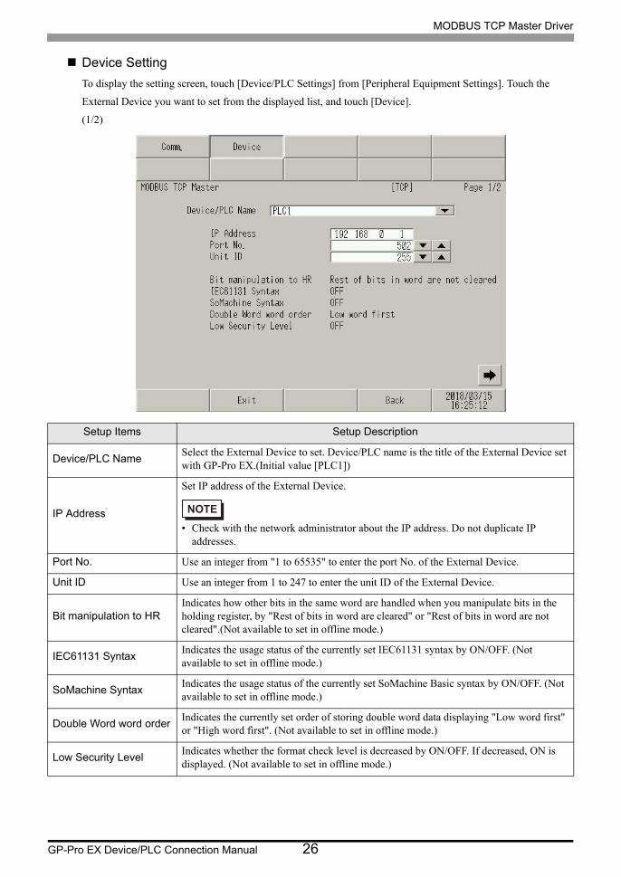
Device Setting
To display the setting screen, touch [Device/PLC Settings] from [Peripheral Equipment Settings]. Touch the
External Device you want to set from the displayed list, and touch [Device].
(1/2)
Setup Items Setup Description
Device/PLC NameSelect the External Device to set. Device/PLC name is the title of the External Device set with GP-Pro EX.(Initial value [PLC1])
IP Address
Set IP address of the External Device.
• Check with the network administrator about the IP address. Do not duplicate IP addresses.
Port No. Use an integer from "1 to 65535" to enter the port No. of the External Device.
Unit ID Use an integer from 1 to 247 to enter the unit ID of the External Device.
Bit manipulation to HRIndicates how other bits in the same word are handled when you manipulate bits in the holding register, by "Rest of bits in word are cleared" or "Rest of bits in word are not cleared".(Not available to set in offline mode.)
IEC61131 SyntaxIndicates the usage status of the currently set IEC61131 syntax by ON/OFF. (Not available to set in offline mode.)
SoMachine SyntaxIndicates the usage status of the currently set SoMachine Basic syntax by ON/OFF. (Not available to set in offline mode.)
Double Word word orderIndicates the currently set order of storing double word data displaying "Low word first" or "High word first". (Not available to set in offline mode.)
Low Security LevelIndicates whether the format check level is decreased by ON/OFF. If decreased, ON is displayed. (Not available to set in offline mode.)

MODBUS TCP Master Driver
GP-Pro EX Device/PLC Connection Manual 27
(2/2)
Setup Items Setup Description
Device/PLC NameSelect the External Device to set. Device/PLC name is the title of the External Device set with GP-Pro EX.(Initial value [PLC1])
Read CoilDisplays the number of max data for device [coil] that can be read for one communication.(Not available to set in offline mode.)
Write CoilDisplays the number of max data for device [coil] that can be written for one communication.(Not available to set in offline mode.)
Read Discrete InputDisplays the number of max data for device [discrete input] that can be read for one communication.(Not available to set in offline mode.)
Read Input RegisterSet the number of max data for device [input register] that can be read for one communication, using 1 to 125 words.
Read Holding RegisterSet the number of max data for device [holding register] that can be read for one communication, using 1 to 125 words.
Write Holding RegisterSet the number of max data for device [holding register] that can be written for one communication, using 1 to 100 words.
Single Bit manipulationIndicates whether to read or write the coil or discrete input in bit units by displaying ON/OFF. If ON is displayed, you can read or write in bit units.(Not available to set in offline mode.)

MODBUS TCP Master Driver
GP-Pro EX Device/PLC Connection Manual 28
5 Supported Devices
Range of supported device address is shown in the table below. Please note that the actually supported range of
the devices varies depending on the External Device to be used. Please check the actual range in the manual of
your External Device.
5.1 Premium/Quantum/M221 Series
: This address can be specified as system data area.
Device Bit Address Word address32
bitsRemarks
Coil 000001 - 065536 000001 - 065521
or
*1
*1 You can set the data storing order in word unit of 32-bit data in the Device Setting dialog box.
Discrete Input 100001 - 165536 100001 - 165521
*2
*2 Write disabled.
Input Register ------ 300001 - 365536
*2
Holding Register400001,0 -
465536,15*3
*3 An access method at the time of Bit Set varies depending on the [Rest of the bits in this word] setting of [Device Setting].- Clear.............................
- Do not clear..................400001,00 - 465536,15
400001 - 465536

MODBUS TCP Master Driver
GP-Pro EX Device/PLC Connection Manual 29
5.2 FCN/FCJ Series
: This address can be specified as system data area.
Device Bit Address Word address32
bitsRemarks
Coil 000001 - 009984 000001 - 009969
or
*1
*1 You can set the data storing order in word unit of 32-bit data in the Device Setting dialog box.
*2
*2 The device access range of the External Device is specified as 1 to 9999, that of the Display, however, as up to 9984, since the Display device is accessible in 16-bit units.
Discrete Input 100001 - 109984 100001 - 109969 *2 *3
*3 Write disabled.
Input Register300001.00 - 309999.15
300001 - 309999 *3
Holding Register400001.00 - 409999.15 *4
*4 An access method at the time of Bit Set varies depending on the [Rest of the bits in this word] setting of [Device Setting].- Clear.............................
- Do not clear .................400001,00 - 409999,15
400001 - 409999

MODBUS TCP Master Driver
GP-Pro EX Device/PLC Connection Manual 30
5.3 Supported Function Codes
The supported function code list is shown below.
5.4 IEC61131Syntax Address Description
The following table shows the equivalence between IEC61131 syntax and MODBUS syntax address descriptions.
Function Code (Hex) Description
FC01(0x01) Read the ON/OFF status of the slave coil (0X).
FC02(0x02) Read the ON/OFF status of the slave discrete input (1X).
FC03(0x03) Read the description of the slave holding register (4X).
FC04(0x04) Read the description of the slave input register (3X).
FC05(0x05) Change (Write) the slave coil (0X) status to either ON or OFF.
FC06(0x06) Change (write) the description of the slave holding register (4X).
FC15(0x0F) Change (Write) the slave consecutive multiple coils (0X) status to either ON or OFF.
FC16(0x10) Change (write) the descriptions of the slave consecutive multiple holding registers (4X).
FC90(0x5A) Used when SoMachine Basic syntax is selected.
• FC15/FC16 are used for writing. FC05/FC06 are used for the External Devices that do not support
the function codes mentioned on the left.
Device
MODBUS Syntax IEC61131 Syntax
Format
0 start 1 start
Format RangeFirst
elementRange
First
elementRange
First
element
Coil 000001+ii = 0 to 65535
000001 %Mii = 0 to 65535
%M00000i = 1 to 65536
%M00001
Discrete Input 100001+ii = 0 to 65535
100001 - - - - -
Input Register (Word)
300001+ii = 0 to 65535
300001 - - - - -
Input Register (Word bit)
300001+i,j
i = 0 to 65535j = 0 to 15
300001,00 - - - - -
Holding Register (Word)
400001+ii = 0 to 65535
400001 %MWii = 0 to 65535 %MW00000
i = 1 to 65536 %MW00001
Holding Register (Word bit)
400001+i,j
i = 0 to 65535j = 0 to 15
400001,00 %Mwi:Xji = 0 to 65535j=0 to 15
%MW00000:X00
i = 1 to 65535j=0 to 15
%MW00001:X00

MODBUS TCP Master Driver
GP-Pro EX Device/PLC Connection Manual 31
• The addresses 100000 and 300000 cannot be accessed using IEC61131 syntax.
• If you apply IEC61131 syntax to a project that has a discrete input or input register already set, the
addresses become "-Undefined-".

MODBUS TCP Master Driver
GP-Pro EX Device/PLC Connection Manual 32
5.5 SoMachine Basic syntax
SoMachine Basic syntax is available only for M221 series.
• TM221ME16R/TM221ME16T
Device Bit Address Word Address32
bitsNotes
Memory bits %M00000 - %M01023 -----
or
*1
*1 High and low relationship of the stored data is specified by the [Double Word word order] setting of [Device Setting].
"4.1 Setup Items in GP-Pro EX" (page 22)
Memory words%MW00000.00 - %MW07999.15
%MW00000 - %MW07999
*2 *3
*2 To use addresses %MD00000 - %MD07998 and %MF00000 - %MF07998 on the External Device, select addresses %MW00000 - %MW07998. Then, set the [Data type] to either [32bit Dec]/[32bit Hex](%MD) or [32bit Float](%MF).
Constant words%KW00000 -
%KW00511.15%KW00000 - %KW00511
*4 *5
Digital inputs%I000.000 - %I000.007 ----- *5 *6
%I001.000 - %I014.031 ----- *7
Digital outputs
%Q000.000 - %Q000.007
----- *6
%Q001.000 - %Q014.031
----- *7
Analog inputs
%IW000.000.00 - %IW000.001.15
%IW000.000 - %IW000.001
*5 *6
%IW001.000.00 - %IW014.007.15
%IW001.000 - %IW014.007
*6 *7
Analog outputs%QW001.000.00 - %QW014.003.15
%QW001.000 - %QW014.003
*6 *7
System bits %S00000 - %S00159 -----
System words%SW00000.00 - %SW00233.15
%SW00000 - %SW00233
*3
Input channel status
%IWS000.000.00 - %IWS000.001.15
%IWS000.000 - %IWS000.001
*5 *6
%IWS001.000.00 - %IWS014.007.15
%IWS001.000 - %IWS014.007
*6 *7
Output channel status%QWS001.000.00 - %QWS014.003.15
%QWS001.000 - %QWS014.003
*6 *7

MODBUS TCP Master Driver
GP-Pro EX Device/PLC Connection Manual 33
*3 The access method for Bit Set varies depending on the [Rest of the bits in this word] setting in the [Individual Device Setting] dialog box.
- Clear......................
- Do not clear........... When bits are written, the Display reads the corresponding word address from the External Device, sets particular bits of that word address ON, and then returns the resulting word address to the External Device. Note that the resulting data may not be correct if you write to the word address from the External Device while the Display is reading from and writing to the External Device.
*4 To use addresses %KD00000 - %KD00510 and %KF00000 - %KF00510 on the External Device, select addresses %KW00000 - %KW00510. Then, set the [Data type] to either [32bit Dec]/[32bit Hex](%MD) or [32bit Float](%MF).
*5 Write disabled
*6 The device address structure is as follows.The module number is mapped to the attached unit.
*7 Available for use only when an I/O module is connected.
%Q xxx . yyyAddress (000 - 255)Module No. (000 - 014)Device
%IW xxx . yyy . zzBit address (00 - 15)Address (000 - 255)Module No. (000 - 014)Device
Bit device Word device

MODBUS TCP Master Driver
GP-Pro EX Device/PLC Connection Manual 34
• TM221ME32TK
Device Bit Address Word Address32
bitsNotes
Memory bits %M00000 - %M01023 -----
or
*1
*1 High and low relationship of the stored data is specified by the [Double Word word order] setting of [Device Setting].
"4.1 Setup Items in GP-Pro EX" (page 22)
Memory words%MW00000.00 - %MW07999.15
%MW00000 - %MW07999
*2 *3
*2 To use addresses %MD00000 - %MD07998 and %MF00000 - %MF07998 on the External Device, select addresses %MW00000 - %MW07998. Then, set the [Data type] to either [32bit Dec]/[32bit Hex](%MD) or [32bit Float](%MF).
*3 The access method for Bit Set varies depending on the [Rest of the bits in this word] setting in the [Individual Device Setting] dialog box.
- Clear......................
- Do not clear........... When bits are written, the Display reads the corresponding word address from the External Device, sets particular bits of that word address ON, and then returns the resulting word address to the External Device. Note that the resulting data may not be correct if you write to the word address from the External Device while the Display is reading from and writing to the External Device.
Constant words%KW00000 -
%KW00511.15%KW00000 - %KW00511
*4 *5
*4 To use addresses %KD00000 - %KD00510 and %KF00000 - %KF00510 on the External Device, select addresses %KW00000 - %KW00510. Then, set the [Data type] to either [32bit Dec]/[32bit Hex](%MD) or [32bit Float](%MF).
Digital inputs%I000.000 - %I000.015 ----- *5 *6
%I001.000 - %I014.031 ----- *7
Digital outputs
%Q000.000 - %Q000.015
----- *6
%Q001.000 - %Q014.031
----- *7
Analog inputs
%IW000.000.00 - %IW000.001.15
%IW000.000 - %IW000.001
*5 *6
%IW001.000.00 - %IW014.007.15
%IW001.000 - %IW014.007
*6 *7
Analog outputs%QW001.000.00 - %QW014.003.15
%QW001.000 - %QW014.003
*6 *7
System bits %S00000 - %S00159 -----
System words%SW00000.00 - %SW00233.15
%SW00000 - %SW00233
*3
Input channel status
%IWS000.000.00 - %IWS000.001.15
%IWS000.000 - %IWS000.001
*5 *6
%IWS001.000.00 - %IWS014.007.15
%IWS001.000 - %IWS014.007
*6 *7
Output channel status%QWS001.000.00 - %QWS014.003.15
%QWS001.000 - %QWS014.003
*6 *7
MODBUS TCP Master Driver
GP-Pro EX Device/PLC Connection Manual 35
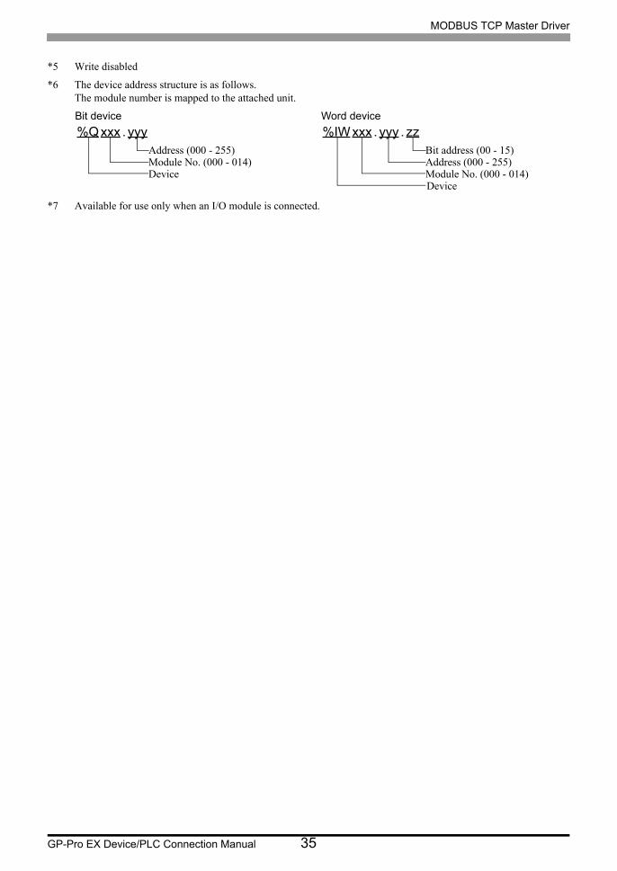
*5 Write disabled
*6 The device address structure is as follows.The module number is mapped to the attached unit.
*7 Available for use only when an I/O module is connected.
%Q xxx . yyyAddress (000 - 255)Module No. (000 - 014)Device
%IW xxx . yyy . zzBit address (00 - 15)Address (000 - 255)Module No. (000 - 014)Device
Bit device Word device

MODBUS TCP Master Driver
GP-Pro EX Device/PLC Connection Manual 36
• TM221CE16
Device Bit Address Word Address32
bitsNotes
Memory bits %M00000 - %M01023 -----
or
*1
*1 High and low relationship of the stored data is specified by the [Double Word word order] setting of [Device Setting].
"4.1 Setup Items in GP-Pro EX" (page 22)
Memory words%MW00000.00 - %MW07999.15
%MW00000 - %MW07999
*2 *3
*2 To use addresses %MD00000 - %MD07998 and %MF00000 - %MF07998 on the External Device, select addresses %MW00000 - %MW07998. Then, set the [Data type] to either [32bit Dec]/[32bit Hex](%MD) or [32bit Float](%MF).
Constant words%KW00000 -
%KW00511.15%KW00000 - %KW00511
*4 *5
Digital inputs%I000.000 - %I000.008 ----- *5 *6
%I001.000 - %I014.031 ----- *5 *6 *7
Digital outputs
%Q000.000 - %Q000.006
----- *6
%Q001.000 - %Q014.031
----- *6 *7
Analog inputs
%IW000.000.00 - %IW000.001.15
%IW000.000 - %IW000.001
*5 *6
%IW001.000.00 - %IW014.007.15
%IW001.000 - %IW014.007
*5 *6 *7
%IW000.100.00 - %IW000.101.15
%IW000.100 - %IW000.101
*5 *6 *8
Analog outputs
%QW001.000.00 - %QW014.003.15
%QW001.000 - %QW014.003
*3 *6 *7
%QW000.100.00 - %QW000.101.15
%QW000.100 - %QW000.101
*3 *6 *9
System bits %S00000 - %S00159 -----
System words%SW00000.00 - %SW00233.15
%SW00000 - %SW00233
*3
Input channel status
%IWS000.000.00 - %IWS000.001.15
%IWS000.000 - %IWS000.001
*5 *6
%IWS001.000.00 - %IWS014.007.15
%IWS001.000 - %IWS014.007
*5 *6 *7
%IWS000.100.00 - %IWS000.101.15
%IWS000.100 - %IWS000.101
*5 *6 *8
Output channel status
%QWS001.000.00 - %QWS014.003.15
%QWS001.000 - %QWS014.003
*5 *6 *7
%QWS000.100.00 - %QWS000.101.15
%QWS000.100 - %QWS000.101
*5 *6 *9

MODBUS TCP Master Driver
GP-Pro EX Device/PLC Connection Manual 37
*3 The access method for Bit Set varies depending on the [Rest of the bits in this word] setting in the [Individual Device Setting] dialog box.
- Clear......................
- Do not clear........... When bits are written, the Display reads the corresponding word address from the External Device, sets particular bits of that word address ON, and then returns the resulting word address to the External Device. Note that the resulting data may not be correct if you write to the word address from the External Device while the Display is reading from and writing to the External Device.
*4 To use addresses %KD00000 - %KD00510 and %KF00000 - %KF00510 on the External Device, select addresses %KW00000 - %KW00510. Then, set the [Data type] to either [32bit Dec]/[32bit Hex](%MD) or [32bit Float](%MF).
*5 Write disabled
*6 The device address structure is as follows.The module number is mapped to the attached unit.
*7 Available for use only when an I/O module is connected.
*8 Available for use only when TMC2AI2, TMC2HOIS01, TMC2PACK01 or TMC2TI2 is connected.
*9 Available for use only when TMC2AQ2V or TMC2AQ2C is connected.
%Q xxx . yyyAddress (000 - 255)Module No. (000 - 014)Device
%IW xxx . yyy . zzBit address (00 - 15)Address (000 - 255)Module No. (000 - 014)Device
Bit device Word device

MODBUS TCP Master Driver
GP-Pro EX Device/PLC Connection Manual 38
• TM221CE24
Device Bit Address Word Address32
bitsNotes
Memory bits %M00000 - %M01023 -----
or
*1
*1 High and low relationship of the stored data is specified by the [Double Word word order] setting of [Device Setting].
"4.1 Setup Items in GP-Pro EX" (page 22)
Memory words%MW00000.00 - %MW07999.15
%MW00000 - %MW07999
*2 *3
*2 To use addresses %MD00000 - %MD07998 and %MF00000 - %MF07998 on the External Device, select addresses %MW00000 - %MW07998. Then, set the [Data type] to either [32bit Dec]/[32bit Hex](%MD) or [32bit Float](%MF).
Constant words%KW00000 -
%KW00511.15%KW00000 - %KW00511
*4 *5
Digital inputs%I000.000 - %I000.013 ----- *5 *6
%I001.000 - %I014.031 ----- *5 *6 *7
Digital outputs
%Q000.000 - %Q000.009
----- *6
%Q001.000 - %Q014.031
----- *6 *7
Analog inputs
%IW000.000.00 - %IW000.001.15
%IW000.000 - %IW000.001
*5 *6
%IW001.000.00 - %IW014.007.15
%IW001.000 - %IW014.007
*5 *6 *7
%IW000.100.00 - %IW000.101.15
%IW000.100 - %IW000.101
*5 *6 *8
Analog outputs
%QW001.000.00 - %QW014.003.15
%QW001.000 - %QW014.003
*3 *6 *7
%QW000.100.00 - %QW000.101.15
%QW000.100 - %QW000.101
*3 *6 *9
System bits %S00000 - %S00159 -----
System words%SW00000.00 - %SW00233.15
%SW00000 - %SW00233
*3
Input channel status
%IWS000.000.00 - %IWS000.001.15
%IWS000.000 - %IWS000.001
*5*6
%IWS001.000.00 - %IWS014.007.15
%IWS001.000 - %IWS014.007
*5 *6 *7
%IWS000.100.00 - %IWS000.101.15
%IWS000.100 - %IWS000.101
*5 *6 *8
Output channel status
%QWS001.000.00 - %QWS014.003.15
%QWS001.000 - %QWS014.003
*5 *6 *7
%QWS000.100.00 - %QWS000.101.15
%QWS000.100 - %QWS000.101
*5 *6 *9
MODBUS TCP Master Driver
GP-Pro EX Device/PLC Connection Manual 39
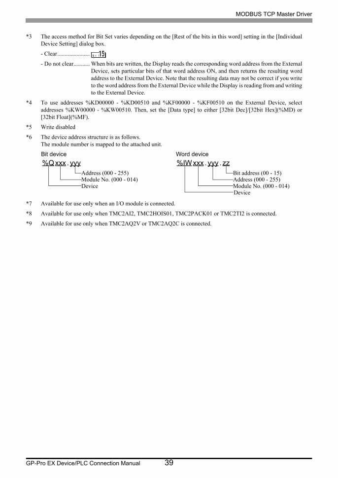
*3 The access method for Bit Set varies depending on the [Rest of the bits in this word] setting in the [Individual Device Setting] dialog box.
- Clear......................
- Do not clear........... When bits are written, the Display reads the corresponding word address from the External Device, sets particular bits of that word address ON, and then returns the resulting word address to the External Device. Note that the resulting data may not be correct if you write to the word address from the External Device while the Display is reading from and writing to the External Device.
*4 To use addresses %KD00000 - %KD00510 and %KF00000 - %KF00510 on the External Device, select addresses %KW00000 - %KW00510. Then, set the [Data type] to either [32bit Dec]/[32bit Hex](%MD) or [32bit Float](%MF).
*5 Write disabled
*6 The device address structure is as follows.The module number is mapped to the attached unit.
*7 Available for use only when an I/O module is connected.
*8 Available for use only when TMC2AI2, TMC2HOIS01, TMC2PACK01 or TMC2TI2 is connected.
*9 Available for use only when TMC2AQ2V or TMC2AQ2C is connected.
%Q xxx . yyyAddress (000 - 255)Module No. (000 - 014)Device
%IW xxx . yyy . zzBit address (00 - 15)Address (000 - 255)Module No. (000 - 014)Device
Bit device Word device

MODBUS TCP Master Driver
GP-Pro EX Device/PLC Connection Manual 40
• TM221CE40
Device Bit Address Word Address32
bitsNotes
Memory bits %M00000 - %M01023 -----
or
*1
Memory words%MW00000.00 - %MW07999.15
%MW00000 - %MW07999
*2 *3
Constant words%KW00000 -
%KW00511.15%KW00000 - %KW00511
*4 *5
Digital inputs%I000.000 - %I000.023 ----- *5 *6
%I001.000 - %I014.031 ----- *5 *6 *7
Digital outputs
%Q000.000 - %Q000.015
----- *6
%Q001.000 - %Q014.031
----- *6 *7
Analog inputs
%IW000.000.00 - %IW000.001.15
%IW000.000 - %IW000.001
*5 *6
%IW001.000.00 - %IW014.007.15
%IW001.000 - %IW014.007
*5 *6 *7
%IW000.100.00 - %IW000.101.15
%IW000.200.00 - %IW000.201.15
%IW000.100 - %IW000.101
%IW000.200 - %IW000.201
*5 *6 *8
Analog outputs
%QW001.000.00 - %QW014.003.15
%QW001.000 - %QW014.003
*3 *6 *7
%QW000.100.00 - %QW000.101.15
%QW000.200.00 - %QW000.201.15
%QW000.100 - %QW000.101
%QW000.200 - %QW000.201
*3 *6 *9
System bits %S00000 - %S00159 -----
System words%SW00000.00 - %SW00233.15
%SW00000 - %SW00233
*3
Input channel status
%IWS000.000.00 - %IWS000.001.15
%IWS000.000 - %IWS000.001
*5 *6
%IWS001.000.00 - %IWS014.007.15
%IWS001.000 - %IWS014.007
*5 *6 *7
%IWS000.100.00 - %IWS000.101.15
%IWS000.200.00 - %IWS000.201.15
%IWS000.100 - %IWS000.101
%IWS000.200 - %IWS000.201
*5 *6 *8
Output channel status
%QWS001.000.00 - %QWS014.003.15
%QWS001.000 - %QWS014.003
*5 *6 *7
%QWS000.100.00 - %QWS000.101.15
%QWS000.200.00 - %QWS000.201.15
%QWS000.100 - %QWS000.101
%QWS000.200 - %QWS000.201
*5 *6 *9
MODBUS TCP Master Driver
GP-Pro EX Device/PLC Connection Manual 41
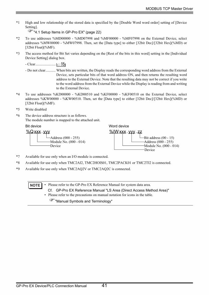
*1 High and low relationship of the stored data is specified by the [Double Word word order] setting of [Device Setting].
"4.1 Setup Items in GP-Pro EX" (page 22)
*2 To use addresses %MD00000 - %MD07998 and %MF00000 - %MF07998 on the External Device, select addresses %MW00000 - %MW07998. Then, set the [Data type] to either [32bit Dec]/[32bit Hex](%MD) or [32bit Float](%MF).
*3 The access method for Bit Set varies depending on the [Rest of the bits in this word] setting in the [Individual Device Setting] dialog box.
- Clear......................
- Do not clear........... When bits are written, the Display reads the corresponding word address from the External Device, sets particular bits of that word address ON, and then returns the resulting word address to the External Device. Note that the resulting data may not be correct if you write to the word address from the External Device while the Display is reading from and writing to the External Device.
*4 To use addresses %KD00000 - %KD00510 and %KF00000 - %KF00510 on the External Device, select addresses %KW00000 - %KW00510. Then, set the [Data type] to either [32bit Dec]/[32bit Hex](%MD) or [32bit Float](%MF).
*5 Write disabled
*6 The device address structure is as follows.The module number is mapped to the attached unit.
*7 Available for use only when an I/O module is connected.
*8 Available for use only when TMC2AI2, TMC2HOIS01, TMC2PACK01 or TMC2TI2 is connected.
*9 Available for use only when TMC2AQ2V or TMC2AQ2C is connected.
• Please refer to the GP-Pro EX Reference Manual for system data area.
Cf. GP-Pro EX Reference Manual "LS Area (Direct Access Method Area)"• Please refer to the precautions on manual notation for icons in the table.
"Manual Symbols and Terminology"
%Q xxx . yyyAddress (000 - 255)Module No. (000 - 014)Device
%IW xxx . yyy . zzBit address (00 - 15)Address (000 - 255)Module No. (000 - 014)Device
Bit device Word device

MODBUS TCP Master Driver
GP-Pro EX Device/PLC Connection Manual 42
6 Device Code and Address Code
Use device code and address code when you set "Device Type & Address" for the address type of the data display
or other devices.
6.1 Premium/Quantum/M221 Series
6.2 FCN/FCJ Series
6.3 SoMachine Basic Syntax
Device Device NameDevice Code
(HEX)Address Code
Coil 0 0080Value of (word address - 1) divided by 16
Discrete Input 1 0081Value of (word address - 1) divided by 16
Input Register 3 0001 Value of (word address - 1)
Holding Register 4 0000 Value of (word address - 1)
Device Device NameDevice Code
(HEX)Address Code
Coil 0 0080Value of (word address - 1) divided by 16
Discrete Input 1 0081Value of (word address - 1) divided by 16
Input Register 3 0001 Value of (word address - 1)
Holding Register 4 0000 Value of (word address - 1)
Device Device NameDevice Code
(HEX)Address Code
Memory words %MW 0000 Value of word address
Constant words %KW 0002 Value of word address
Analog inputs %IW 0008 Value of word address
Analog outputs %QW 0009 Value of word address
System words %SW 0004 Value of word address
Input channel status %IWS 000A Value of word address
Output channel status %QWS 000B Value of word address

MODBUS TCP Master Driver
GP-Pro EX Device/PLC Connection Manual 43
7 Error Messages
Error messages are displayed on the screen of the Display as follows: "No. : Device Name: Error Message(Error
Occurrence Area)". Each description is shown below.
Display Examples of Error Messages
"RHAA035: PLC1: Error has been responded for device write command (Error Code: 2[02H])"
Item Description
No. Error No.
Device NameName of the External Device where an error has occurred. Device/PLC name is the title of the External Device set with GP-Pro EX.(Initial value [PLC1])
Error Message Displays messages related to an error that has occurred.
Error Occurrence Area
Displays the IP address or device address of the External Device where an error has occurred, or error codes received from the External Device.
• IP addresses are displayed as "IP address (Decimal): MAC address (Hex)".• Device addresses are displayed as "Address: Device address".• Received error codes are displayed as "Decimal [Hex]".
• Refer to your External Device manual for details on received error codes.
• Refer to "Display-related errors" in "Maintenance/Troubleshooting Guide" for details on the error
messages common to the driver.

MODBUS TCP Master Driver
GP-Pro EX Device/PLC Connection Manual 44