Modal analysis of Pneumatic two Finger Robotic hand by ... · Modal analysis of Pneumatic two...
9
International Journal of Engineering & Technology IJET-IJENS Vol:13 No:03 1 I J E N S IJENS 3 201 June IJENS © - IJET - 5656 - 30203 1 Modal analysis of Pneumatic two Finger Robotic hand by Finite Element Analysis and Experimental Testing Safeen Yassen Qassab, Hussein Ali Sultan, Shirin Othman Mohammad College of Engineering, Salahaddin University – Hawler, Iraq Abstract-- The objective of the present work was studying the technique of modal analysis using theoretical, numerical and experimental methods .Two axis modal finger of pneumatic robotic hand was designed and built. The theoretical modeling was done by deriving equations of stress and deflection depending on the free body diagram of robotic clamp, finite element analysis was performed using Comsol Multi physics 3.5a software program. The modal testing was done by dial and pressure gauges. For each method dynamic stress and deflection were found, and the results from all three analyses were compared and proved that the rated deflection and stresses that calculated from the theoretical calculation make a good agreement with the results obtained from the finite element analysis and experimental testing. The acceptable maximum holding weight of designed hand was found to be 400g. Index Term-- pneumatic hand, two axis finger, Comsol software, Finite Element Analysis. I. INTRODUCTION Robotic grippers are the part of robots end effectors that have the capability to grasp definite objects and reposition it according to requirement. They are widely used for automated manufacturing, assembly, and packing. Grippers are actuated by various mechanisms which include mechanical, electrical, hydraulic and pneumatic drives. Among this the widely used one is the hydraulic grippers but most favorable one is pneumatic gripper [1]. Gob-Soon Kim, 2001 [2] designed a two-axis force sensor of robots finger using several parallel plate beams the derived equations for calculating strain in the beams in order to design the two–axis force sensor sensing element, the reliability of derived equations are verified by using FEA of the sensing element. Wang, 2002 [3] designed and developed the three-fingered gripper actuated by a linear servo actuator for precise speed and position control was capable of handling a large variety of objects. The above grippers can stably grasp objects, many of them can carry out by the force control of grasping direction but not known for grasping force. Higashimori, 2005 [4] discussed the design of the 100g capturing robot from the point of view of dynamic pre –shaping where all finger links make contact with the target object simultaneously, mechanical parameters were determined by mathematically formulating dynamic pre-shaping problem and experimentally. Ho Choi & Koc, 2006 [5] present feasibility test results of a flexible gripper design, a flexible gripper based on the use of compliant materials (i.e., rubber) with pneumatic inflation was designed, analyzed, built and tested. Parametric FE analyses were conducted to investigate the effects of process and design parameters, such as rubber material, pressure, initial jaw displacement and friction. Based on the FEA results, a simple, single rubber pocketed flexible gripper was designed and built. Feasibility experiments were performed to demonstrate and obtain an overall understanding about the capability and limitations of the gripper. He proved that objects with different shapes (cylindrical, prismatic and complex), weight (50 g–20 kg.), and types (egg, steel hemi- spheres, wax cylinders, etc.) could be picked and placed without any loss of control of the object. Biswal, 2010 [6] designed a two jaw actuated gripper which was different from the conventional cam and follower gripper in the way that controlled movement of the jaws was done with the help of pneumatic cylinders using air pressure, and the force and torque for the gripper have been calculated for different set of conditions. Aaron and Robert 2010[7] demonstrate a novel adaptive and compliant grasper that can grasp objects spanning a wide range of size, shape, mass, and position/orientation using only a single actuator. The hand is constructed using polymer-based Shape Deposition Manufacturing (SDM) and has superior robustness properties, making it able to withstand large impacts without damage. And also they present the results of two experiments to demonstrate that the SDM Hand can reliably grasp objects in the presence of large positioning errors, while keeping acquisition contact forces low. In the first, they evaluate the amount of allowable manipulator positioning error that results in a successful grasp. In the second experiment, the hand autonomously grasps a wide range of spherical objects positioned randomly across the workspace, using feed-forward control of the hand. Tian & Jia, 2011 [8] numerically studied two-finger grasping of deformable curve-like objects under frictional contacts. Deformation is modeled by a degenerated version of the thin shell theory. Several differences from rigid body grasping were shown. Under a squeeze, the friction cone at each finger contact rotates in a direction that depends on the deformable object’s global geometry. The magnitude of the grasping force has to be above certain threshold to achieve equilibrium, and the set of feasible finger placements may increase significantly compared to that for a rigid object of the same shape. Finally, the ability to resist disturbance was bounded in the sense that increasing the magnitude of an external force could result in the breaking of the grasp. Aaron & Robert 2011[9] examined joint coupling in under actuated robotic grippers for unstructured environments where object properties and location may not be well known. A simplified grasper consisting of a pair of two-link planar fingers with compliant revolute joints was simulated as it grasped a target object. The joint coupling configuration of the gripper was varied in order to maximize successful grasp range and minimize contact forces for a wide range of target object sizes and positions. They used various numbers of actuators in order to test performance
Transcript of Modal analysis of Pneumatic two Finger Robotic hand by ... · Modal analysis of Pneumatic two...

International Journal of Engineering & Technology IJET-IJENS Vol:13 No:03 1
I J E N S IJENS 3201 JuneIJENS © -IJET-5656-302031
Modal analysis of Pneumatic two Finger
Robotic hand by Finite Element Analysis and
Experimental Testing Safeen Yassen Qassab, Hussein Ali Sultan, Shirin Othman Mohammad
College of Engineering, Salahaddin University – Hawler, Iraq
Abstract-- The objective of the present work was studying the
technique of modal analysis using theoretical, numerical and
experimental methods .Two axis modal finger of pneumatic
robotic hand was designed and built. The theoretical modeling
was done by deriving equations of stress and deflection
depending on the free body diagram of robotic clamp, finite
element analysis was performed using Comsol Multi physics
3.5a software program. The modal testing was done by dial
and pressure gauges. For each method dynamic stress and
deflection were found, and the results from all three analyses
were compared and proved that the rated deflection and
stresses that calculated from the theoretical calculation make a
good agreement with the results obtained from the finite
element analysis and experimental testing. The acceptable
maximum holding weight of designed hand was found to be
400g.
Index Term-- pneumatic hand, two axis finger, Comsol
software, Finite Element Analysis.
I. INTRODUCTION
Robotic grippers are the part of robots end effectors that
have the capability to grasp definite objects and reposition
it according to requirement. They are widely used for
automated manufacturing, assembly, and packing. Grippers
are actuated by various mechanisms which include
mechanical, electrical, hydraulic and pneumatic drives.
Among this the widely used one is the hydraulic grippers
but most favorable one is pneumatic gripper [1].
Gob-Soon Kim, 2001 [2] designed a two-axis force sensor
of robots finger using several parallel plate beams the
derived equations for calculating strain in the beams in order
to design the two–axis force sensor sensing element, the
reliability of derived equations are verified by using FEA of
the sensing element. Wang, 2002 [3] designed and
developed the three-fingered gripper actuated by a linear
servo actuator for precise speed and position control was
capable of handling a large variety of objects. The above
grippers can stably grasp objects, many of them can carry
out by the force control of grasping direction but not known
for grasping force. Higashimori, 2005 [4] discussed the
design of the 100g capturing robot from the point of view of
dynamic pre –shaping where all finger links make contact
with the target object simultaneously, mechanical
parameters were determined by mathematically formulating
dynamic pre-shaping problem and experimentally. Ho Choi
& Koc, 2006 [5] present feasibility test results of a flexible
gripper design, a flexible gripper based on the use of
compliant materials (i.e., rubber) with pneumatic inflation
was designed, analyzed, built and tested. Parametric FE
analyses were conducted to investigate the effects of process
and design parameters, such as rubber material, pressure,
initial jaw displacement and friction. Based on the FEA
results, a simple, single rubber pocketed flexible gripper was
designed and built. Feasibility experiments were performed
to demonstrate and obtain an overall understanding about
the capability and limitations of the gripper. He proved that
objects with different shapes (cylindrical, prismatic and
complex), weight (50 g–20 kg.), and types (egg, steel hemi-
spheres, wax cylinders, etc.) could be picked and placed
without any loss of control of the object. Biswal, 2010 [6]
designed a two jaw actuated gripper which was different
from the conventional cam and follower gripper in the way
that controlled movement of the jaws was done with the
help of pneumatic cylinders using air pressure, and the force
and torque for the gripper have been calculated for different
set of conditions. Aaron and Robert 2010[7] demonstrate a
novel adaptive and compliant grasper that can grasp objects
spanning a wide range of size, shape, mass, and
position/orientation using only a single actuator. The hand is
constructed using polymer-based Shape Deposition
Manufacturing (SDM) and has superior robustness
properties, making it able to withstand large impacts without
damage. And also they present the results of two
experiments to demonstrate that the SDM Hand can reliably
grasp objects in the presence of large positioning errors,
while keeping acquisition contact forces low. In the first,
they evaluate the amount of allowable manipulator
positioning error that results in a successful grasp. In the
second experiment, the hand autonomously grasps a wide
range of spherical objects positioned randomly across the
workspace, using feed-forward control of the hand. Tian &
Jia, 2011 [8] numerically studied two-finger grasping of
deformable curve-like objects under frictional contacts.
Deformation is modeled by a degenerated version of the thin
shell theory. Several differences from rigid body grasping
were shown. Under a squeeze, the friction cone at each
finger contact rotates in a direction that depends on the
deformable object’s global geometry. The magnitude of the
grasping force has to be above certain threshold to achieve
equilibrium, and the set of feasible finger placements may
increase significantly compared to that for a rigid object of
the same shape. Finally, the ability to resist disturbance was
bounded in the sense that increasing the magnitude of an
external force could result in the breaking of the grasp.
Aaron & Robert 2011[9] examined joint coupling in under
actuated robotic grippers for unstructured environments
where object properties and location may not be well
known. A simplified grasper consisting of a pair of two-link
planar fingers with compliant revolute joints was simulated
as it grasped a target object. The joint coupling
configuration of the gripper was varied in order to maximize
successful grasp range and minimize contact forces for a
wide range of target object sizes and positions. They used
various numbers of actuators in order to test performance
International Journal of Engineering & Technology IJET-IJENS Vol:13 No:03 2
I J E N S IJENS 3201 JuneIJENS © -IJET-5656-302031
for varying degrees of under actuation; they proved that an
actuator for each gripper finger performs no better than a
single actuator for both fingers. Fei Chen 2012 [10] was
designed and built an intelligent robotic hand – i-Hand,
which was equipped with multiple small sensors, designed
and built for successful accomplishment of the assembly
task, and also for human and robot coworker coordinated
assembly. Mating connectors by robot, as an experimental
case was studied to evaluate i-Hand performance. Naoki
Saito 2012 [11] was examined a placing motion of a grasped
object by a robot hand equipped with a flexible sensor on
the finger, They derived dynamic model of the motion, The
validity of the model and the effect of the sensor’s flexibility
were examined through simulation, then confirmed
experimentally that the robot hand puts down the object
without an excessive impact force using the obtained
trajectory. Alberto Matthew 2012[12] introduced a principle
to guide the design of finger form: invariance of contact
geometry over some continuum of varying shape and/or
pose of the grasped object in the plane. They presented a
general technique to solve for finger form, given a
continuum of shape or pose variation and a property to be
held invariant. They applied the technique to derive scale-
invariant and pose-invariant grasps for disks, and also
explore the principle’s application to many common devices
from jar wrenches to rock-climbing cams.
II. AIM OF THE RESEARCH
The purpose of this work was design and analyzing the
robot’s hand for increasing the surface contact of grasping
mechanism, easily detects the effect of grasp and gravity
forces, light in weight, and more economy. It composed of
two curved fingers using several plate beams made from
low carbon steel, actuated pneumatically. In order to stably
grasp an unknown object, the finger should detect the force
of grasping direction and the force of gravity direction, and
perform the force control using pneumatic actuator [2,4 ,5].
The precision accuracy of two finger robot hand can be
estimated by non-linearity, repeatability, and relative error.
The relative errors can be reduced by accurately locating the
dial gauge of deflection [13].
The equations which were used for calculating the
deformation and stress of the beams were derived, and these
equations were used in determining the value of stress and
deformation of designed robotic hand. The reliability of the
derived equations was verified by performing a Finite
Element Analysis in COMSOL Multi physics 3.5a software
program for each part of the hand. The validity of the
calculation condition of the approaching allowable holding
mass was confirmed through computer simulation. The
deflection obtained through this process was compared with
theoretical analysis, and the deflections obtained from
theoretical analysis were used to determine the attachment
location of the dial gauge.
III. MATERIALS AND METHODS
Modeling of the robotic hand
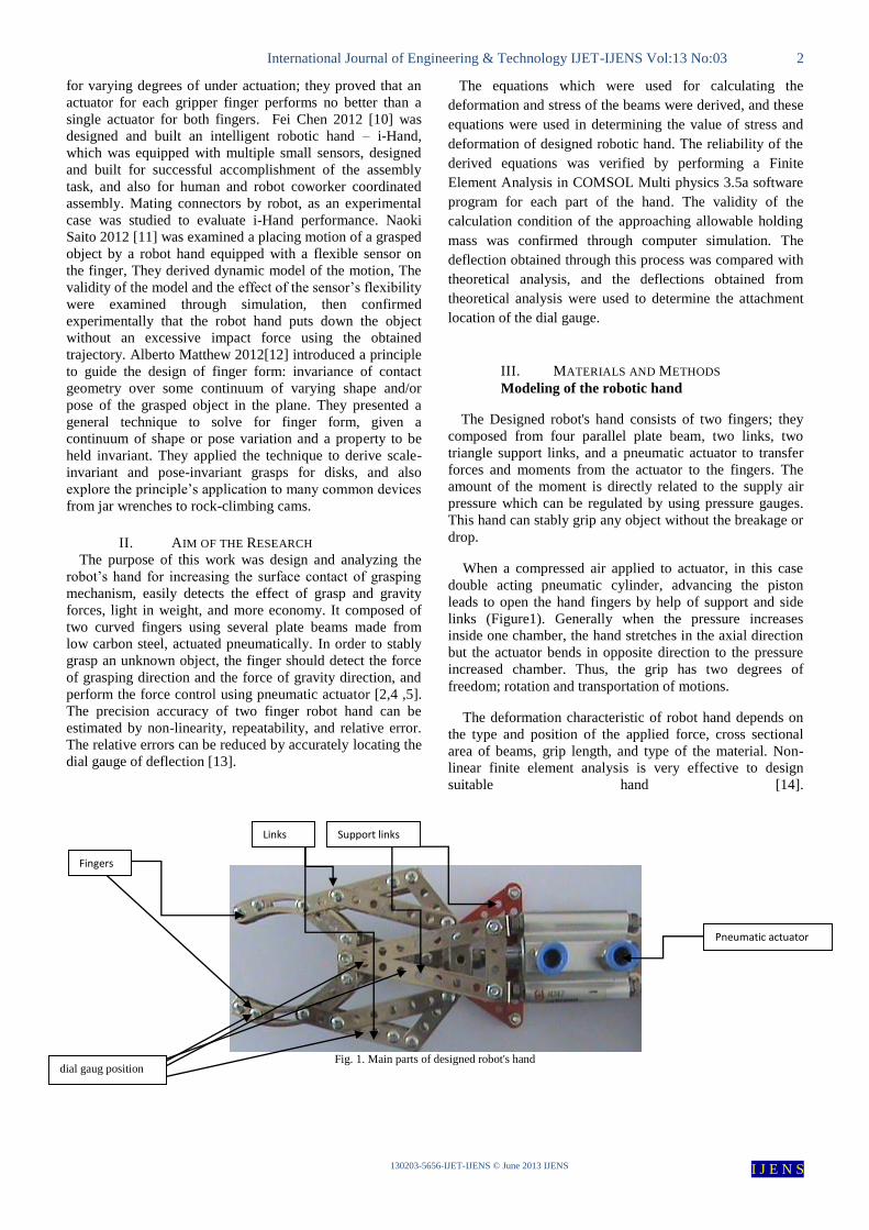
The Designed robot's hand consists of two fingers; they
composed from four parallel plate beam, two links, two
triangle support links, and a pneumatic actuator to transfer
forces and moments from the actuator to the fingers. The
amount of the moment is directly related to the supply air
pressure which can be regulated by using pressure gauges.
This hand can stably grip any object without the breakage or
drop.
When a compressed air applied to actuator, in this case
double acting pneumatic cylinder, advancing the piston
leads to open the hand fingers by help of support and side
links (Figure1). Generally when the pressure increases
inside one chamber, the hand stretches in the axial direction
but the actuator bends in opposite direction to the pressure
increased chamber. Thus, the grip has two degrees of
freedom; rotation and transportation of motions.
The deformation characteristic of robot hand depends on
the type and position of the applied force, cross sectional
area of beams, grip length, and type of the material. Non-
linear finite element analysis is very effective to design
suitable hand [14].
Fig. 1. Main parts of designed robot's hand
dial gaug position
Links
Fingers
Support links
Pneumatic actuator
International Journal of Engineering & Technology IJET-IJENS Vol:13 No:03 3
I J E N S IJENS 3201 JuneIJENS © -IJET-5656-302031
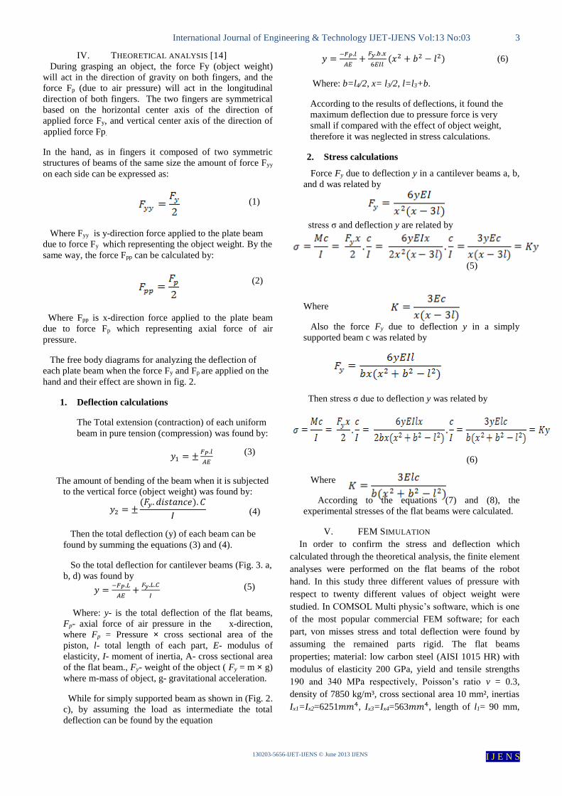
IV. THEORETICAL ANALYSIS [14]
During grasping an object, the force Fy (object weight)
and the act in the direction of gravity on both fingers, will
longitudinal (due to air pressure) will act in the pforce F
direction of both fingers. The two fingers are symmetrical
based on the horizontal center axis of the direction of
, and vertical center axis of the direction of yapplied force F
.force Fpapplied
In the hand, as in fingers it composed of two symmetric
structures of beams of the same size the amount of force Fyy
on each side can be expressed as:
Where Fyy is y-direction force applied to the plate beam
due to force Fy which representing the object weight. By the
same way, the force Fpp can be calculated by:
Where Fpp is x-direction force applied to the plate beam
due to force Fp which representing axial force of air
pressure.
The free body diagrams for analyzing the deflection of
applied on the arep Fand yeach plate beam when the force F
hand and their effect are shown in fig. 2.
1. Deflection calculations
The Total extension (contraction) of each uniform
beam in pure tension (compression) was found by:
𝑦1 = ±𝐹𝑃.𝑙
𝐴𝐸
The amount of bending of the beam when it is subjected
to the vertical force (object weight) was found by:
𝑦2 = ±(𝐹𝑦. 𝑑𝑖𝑠𝑡𝑎𝑛𝑐𝑒). 𝐶
𝐼
Then the total deflection (y) of each beam can be
found by summing the equations (3) and (4).
So the total deflection for cantilever beams (Fig. 3. a,
b, d) was found by
𝑦 =−𝐹𝑃.𝐿
𝐴𝐸+
𝐹𝑦.𝐿.𝐶
𝐼
Where: y- is the total deflection of the flat beams,
Fp- axial force of air pressure in the x-direction,
where Fp = Pressure × cross sectional area of the
piston, l- total length of each part, E- modulus of
elasticity, I- moment of inertia, A- cross sectional area
of the flat beam., Fy- weight of the object ( Fy = m × g)
where m-mass of object, g- gravitational acceleration.
While for simply supported beam as shown in (Fig. 2.
c), by assuming the load as intermediate the total
deflection can be found by the equation
𝑦 =−𝐹𝑃.𝑙
𝐴𝐸+
𝐹𝑦.𝑏.𝑥
6𝐸𝐼𝑙(𝑥2 + 𝑏2 − 𝑙2) (6)
Where: b=l4/2, x= l3/2, l=l3+b.
According to the results of deflections, it found the
maximum deflection due to pressure force is very
small if compared with the effect of object weight,
therefore it was neglected in stress calculations.
2. Stress calculations
Force Fy due to deflection y in a cantilever beams a, b,
and d was related by
stress σ and deflection y are related by
(5)
Where
Also the force Fy due to deflection y in a simply
supported beam c was related by
Then stress σ due to deflection y was related by
(6)
Where
According to the equations (7) and (8), the
experimental stresses of the flat beams were calculated.
V. FEM SIMULATION
In order to confirm the stress and deflection which
calculated through the theoretical analysis, the finite element
analyses were performed on the flat beams of the robot
hand. In this study three different values of pressure with
respect to twenty different values of object weight were
studied. In COMSOL Multi physic’s software, which is one
of the most popular commercial FEM software; for each
part, von misses stress and total deflection were found by
assuming the remained parts rigid. The flat beams
properties; material: low carbon steel (AISI 1015 HR) with
modulus of elasticity 200 GPa, yield and tensile strengths
190 and 340 MPa respectively, Poisson’s ratio v = 0.3,
density of 7850 kg/m³, cross sectional area 10 mm², inertias
Ix1=Ix2=6251𝑚𝑚4, Ix3=Ix4=563𝑚𝑚4, length of l1= 90 mm,
(2)
(6)
(5)
(6)
(3)
(4)
(1)
International Journal of Engineering & Technology IJET-IJENS Vol:13 No:03 4
I J E N S IJENS 3201 JuneIJENS © -IJET-5656-302031
l2= 60 mm, l3= 90 mm, l4=70 mm, the total mass of grip is
150 g, and a pneumatic double acting cylinder with 32 mm
piston diameter, length of stroke 20 mm was used Figure 3
shows the FEM model of the robot grip.
Fig. 2. Free body diagram of plate beams under the force Fy, and air pressure Fp.
VI. RESULTS
A. Theoretical results
Depending on equations derived from hand modeling the
stresses and deflections for each part of the built hand the
results were as follows:
(a) Upper beam support link, part one
(b) Lower beam support link, part two
(c) Pressure transmitting link, part three
(d) Robot finger, part four
Fyy
MFyz
ppF
l1
Fyy
Fpp
MFyz
l2
Beam
1
Beam
Fy
Fpp
l4
FyzM
l4/2 l3 ppF
yyF
International Journal of Engineering & Technology IJET-IJENS Vol:13 No:03 5
I J E N S IJENS 3201 JuneIJENS © -IJET-5656-302031
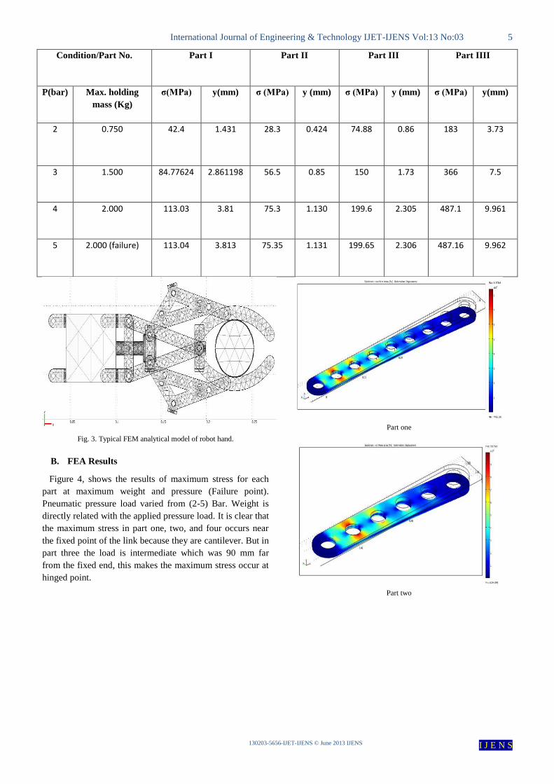
Condition/Part No. Part I Part II Part III Part IIII
P(bar) Max. holding
mass (Kg)
σ(MPa) y(mm) σ (MPa) y (mm) σ (MPa) y (mm) σ (MPa) y(mm)
2 0.750 42.4 1.431 28.3 0.424 74.88 0.86 183 3.73
3 1.500 84.77624 2.861198 56.5 0.85 150 1.73 366 7.5
4 2.000 113.03 3.81 75.3 1.130 199.6 2.305 487.1 9.961
5 2.000 (failure) 113.04 3.813 75.35 1.131 199.65 2.306 487.16 9.962
Fig. 3. Typical FEM analytical model of robot hand.
B. FEA Results
Figure 4, shows the results of maximum stress for each
part at maximum weight and pressure (Failure point).
Pneumatic pressure load varied from (2-5) Bar. Weight is
directly related with the applied pressure load. It is clear that
the maximum stress in part one, two, and four occurs near
the fixed point of the link because they are cantilever. But in
part three the load is intermediate which was 90 mm far
from the fixed end, this makes the maximum stress occur at
hinged point.
Part one
Part two
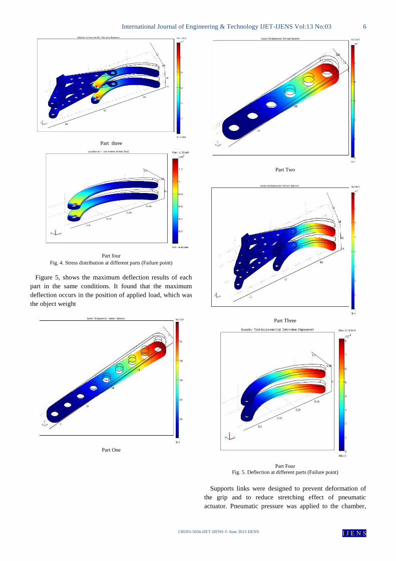
International Journal of Engineering & Technology IJET-IJENS Vol:13 No:03 6
I J E N S IJENS 3201 JuneIJENS © -IJET-5656-302031
Part three
Part four
Fig. 4. Stress distribution at different parts (Failure point)
Figure 5, shows the maximum deflection results of each
part in the same conditions. It found that the maximum
deflection occurs in the position of applied load, which was
the object weight
Part One
Part Two
Part Three
Part Four
Fig. 5. Deflection at different parts (Failure point)
Supports links were designed to prevent deformation of
the grip and to reduce stretching effect of pneumatic
actuator. Pneumatic pressure was applied to the chamber,
International Journal of Engineering & Technology IJET-IJENS Vol:13 No:03 7
I J E N S IJENS 3201 JuneIJENS © -IJET-5656-302031
while pressure in other chamber was kept at atmospheric
pressure.
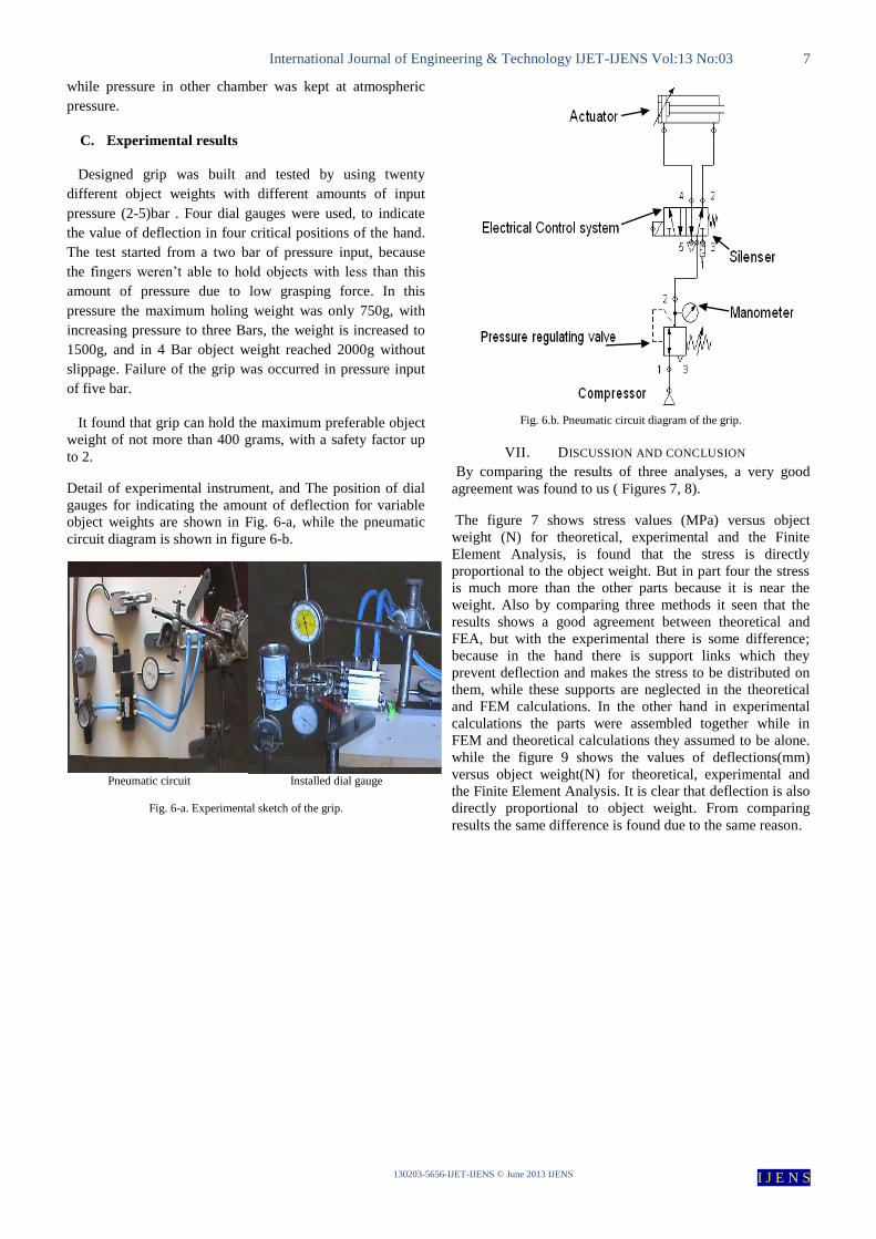
C. Experimental results
Designed grip was built and tested by using twenty
different object weights with different amounts of input
pressure (2-5)bar . Four dial gauges were used, to indicate
the value of deflection in four critical positions of the hand.
The test started from a two bar of pressure input, because
the fingers weren’t able to hold objects with less than this
amount of pressure due to low grasping force. In this
pressure the maximum holing weight was only 750g, with
increasing pressure to three Bars, the weight is increased to
1500g, and in 4 Bar object weight reached 2000g without
slippage. Failure of the grip was occurred in pressure input
of five bar.
It found that grip can hold the maximum preferable object
weight of not more than 400 grams, with a safety factor up
to 2.
Detail of experimental instrument, and The position of dial
gauges for indicating the amount of deflection for variable
object weights are shown in Fig. 6-a, while the pneumatic
circuit diagram is shown in figure 6-b.
Pneumatic circuit Installed dial gauge
Fig. 6-a. Experimental sketch of the grip.
Fig. 6.b. Pneumatic circuit diagram of the grip.
VII. DISCUSSION AND CONCLUSION
By comparing the results of three analyses, a very good
agreement was found to us ( Figures 7, 8).
The figure 7 shows stress values (MPa) versus object
weight (N) for theoretical, experimental and the Finite
Element Analysis, is found that the stress is directly
proportional to the object weight. But in part four the stress
is much more than the other parts because it is near the
weight. Also by comparing three methods it seen that the
results shows a good agreement between theoretical and
FEA, but with the experimental there is some difference;
because in the hand there is support links which they
prevent deflection and makes the stress to be distributed on
them, while these supports are neglected in the theoretical
and FEM calculations. In the other hand in experimental
calculations the parts were assembled together while in
FEM and theoretical calculations they assumed to be alone.
while the figure 9 shows the values of deflections(mm)
versus object weight(N) for theoretical, experimental and
the Finite Element Analysis. It is clear that deflection is also
directly proportional to object weight. From comparing
results the same difference is found due to the same reason.

International Journal of Engineering & Technology IJET-IJENS Vol:13 No:03 8
I J E N S IJENS 3201 JuneIJENS © -IJET-5656-302031
Fig. 7. Relationship between Maximum stress and object weight by three analysis.
Fig. 8. Relationship between deflection and object weight by three analysis.
CONCLUSION This investigation shows a new design and prototyping
method for pneumatic grip hand. The method enables us to
Design pneumatic gripper optimally and efficiently
based on static analysis using non-linear finite
element method.
A Pneumatic robot hand with two degree of
freedom which can be used to hold and transfer

International Journal of Engineering & Technology IJET-IJENS Vol:13 No:03 9
I J E N S IJENS 3201 JuneIJENS © -IJET-5656-302031
objects in (Kg) not more than quarter of its
working pressure in Bars.
COMSOL Multi physics is dependable soft ware
for the purposes of analyzing and design.
Using finite element analysis is the best method for
design purposes because it’s quicker and
dependable method.
In comparison between three deferent analyses the
results are near to each other with error about to
5%, therefore the derived equations in this paper
are judged to be useful in the stress and the
deflection for designing the grip.
REFERENCES [1] Pneumatics hand book, by Antony barber, 8th edition, 1997. [2] Gob-Soon Kim, “Design of two-axis force sensor of robots
finger”, vol.3, No.1, March, 2001.
[3] JianqiangWang “Intelligent gripper design and application for automated part recognition and gripping”, October 2002.
[4] Mitsuru Higashimori, Makoto Kaneko, Akio Namiki, Masatoshi
Ishikawa, Design of 100G Capturing robot based on dynamic preshaping, International journal of robotics research, volume
24 No. 9, pp 743-753, September 2005.
[5] Ho Choi, Muammer Koc ,”Design and feasibility tests of a flexible gripper based on inflatable rubber pockets”,.
International Journal of Machine Tools & Manufacture 2006:46;
1350–1361. [6] B.B.Biswal,” Design and development of a two-jaw parallel
pneumatic gripper for robotic manipulation”, 2010.
[7] Aaron M. Dollar, Robert D. Howe The Highly Adaptive SDM Hand: Design and Performance Evaluation,
International Journal of Robotics Research, April
2010; vol. 29, 5: pp. 585-597.,first published on February 2, 2010.
[8] Jiang Tian and Yan-Bin Jia, “Toward Two-Finger Grasping of
Deformable Curve-like Objects”, Department of Computer Science, Iowa State University, Ames, 2011, USA.
[9] Aaron M Dollar & Robert D Howe, Joint coupling design of
under actuated hands for unstructured environments, International Journal of Robotics Research ,vol. 30 , pp1157-
1169August 1, 2011.
[10] Fei Chen, Kosuke Sekiyama, Baiqing Sun, Pei Di, Jian Huang, Hironobu Sasaki and Toshio Fukuda, Design and Application of
an Intelligent Robotic Gripper for Accurate and Tolerant
Electronic Connector Mating, Journal of Robotics andMechatronicsVol.24 No.3, pp. 441-451,2012.
[11] Naoki Saito, Toshiyuki Satoh, Yoshinao Suzuki, and Hideharu
Okano, Placing Motion of an Object by a Robot Hand with a Flexible Sensor, Journal of Robotics andMechatronicsVol.24 ,
No.1, 2012.
[12] Alberto Rodriguez, Matthew T Mason, Grasp invariance, International Journal of Robotics Research vol. 31, pp. 236-248
February 1, 2012 .
[13] G. S. Kim, “Design and strain analysis of precision 3-component load cell”, International Journal of KSPE, 2000.
[14] Richard G. Budynas., and J. Keith Nisbett., Shigley's
Mechanical Engineering Design, 8th edition, McGraw-Hill, 2008.
[15] Holmdel, NJ, USA ; Ping Hsu ; Sastry, S.S., Dynamic control of sliding by robot hands for regrasping, journal of Robotics and
Automation, Volume:8 , Issue: 1 , pp 42-52, 2002.