MOD Architectural Framework Acquisition Community of ... Acquisition Deskbook v0.9.pdf · MOD...
138
- 1 - MODAF-M10-004 MINISTRY OF DEFENCE MOD Architectural Framework Acquisition Community of Interest Deskbook Version 0.9 29 July 2005 Prepared by:- Approved by:- CROWN COPYRIGHT 2005. THIS DOCUMENT IS THE PROPERTY OF HER BRITANNIC MAJESTY’S GOVERNMENT. This material (other than the Royal Arms and departmental or agency logos) may be reproduced free of charge in any format or medium provided it is reproduced accurately and not used in a misleading context. Where this material is being republished or copied to others, the source of the material must be identified and the copyright status acknowledged. For further information on Crown Copyright policy and licensing arrangements, see the guidance featured on the HMSO website http://www.opsi.gov.uk
Transcript of MOD Architectural Framework Acquisition Community of ... Acquisition Deskbook v0.9.pdf · MOD...

- 1 -
MODAF-M10-004
MINISTRY OF DEFENCE
MOD Architectural Framework
Acquisition Community of Interest Deskbook
Version 0.9
29 July 2005
Prepared by:-
Approved by:-
CROWN COPYRIGHT 2005.
THIS DOCUMENT IS THE PROPERTY OF HER BRITANNIC MAJESTY’S GOVERNMENT. This material (other than the Royal Arms and departmental or agency logos) may be reproduced free of charge in any format or medium provided it is reproduced accurately and not used in a misleading context. Where this material is being republished or copied to others, the source of the material must be identified and the copyright status acknowledged.
For further information on Crown Copyright policy and licensing arrangements, see the guidance featured on the HMSO website http://www.opsi.gov.uk

- 2 -
RECORD OF CHANGES
This page will be updated and re-issued with each amendment. It provides an authorisation for the amendment and a checklist to the current amendment number.
Issue No. Date Revision Details
Draft 0.1 11 April 2005 First Draft
Draft 0.2 15 June 2005 Incorporation of comments from MODAF Partners team and Acquisition Community of Interest (COI) initial workshop
Draft 0.3 17 June 2005 Incorporation of comments from PDG Standardisation Group and draft Architectural Process
Draft 0.4 8 July 2005 Incorporation of comments from Acquisition COI follow-up workshop and individual reviews, introductory section re-structured, re-formatted and document structure changed by workstream rather than CADMID stage
Version 0.9 29 July 2005 Initial publication, updated with Review comments, and Review Board decisions
- 3 -
Acquisition MODAF Deskbook - Table of Contents
1. Foreword........................................................................................................... 5
2. Introduction ...................................................................................................... 6 2.1 What is MODAF? ........................................................................................ 6 2.2 Guide to Deskbook...................................................................................... 7
2.2.1 Purpose ............................................................................................... 7 2.2.2 Context ................................................................................................ 7 2.2.3 Deskbook Structure.............................................................................. 9
3. MODAF Relationship to Acquisition Business Processes and Activities.. 10 3.1 Architecture Development Process ........................................................... 10
3.1.1 Six-Stage Architecture Development Process.................................... 10 3.1.2 Architectural Data Sources................................................................. 11 3.1.3 Application to Acquisition Process...................................................... 12 3.1.4 Overview of MODAF View use........................................................... 12 3.1.5 Ensuring Views are MODAF compliant - hybrid and modified Views .. 13
3.2 Acquisition Process................................................................................... 13 3.3 Project Management ................................................................................. 15
3.3.1 Form the IPT...................................................................................... 17 3.3.2 Systems Engineering Management Plan............................................ 18 3.3.3 Initial Gate.......................................................................................... 18 3.3.4 Manage dependency risks ................................................................. 19 3.3.5 Main Gate .......................................................................................... 20 3.3.6 Place contract(s) to meet the SRD..................................................... 20 3.3.7 Wind down of IPT............................................................................... 21
3.4 Requirements Management ...................................................................... 22 3.4.1 User Requirements Document (URD) ................................................ 24 3.4.2 Linkage between User and System Requirements............................. 24 3.4.3 System Requirements Document (SRD) ............................................ 25 3.4.4 Integrated Testing, Evaluation and Acceptance ................................. 30
3.5 Systems / Technology............................................................................... 32 3.5.1 Identify technology and procurement options ..................................... 34 3.5.2 Demonstrate ability to deliver integrated capability............................. 36 3.5.3 Technology insertion .......................................................................... 36
3.6 Industry / Suppliers ................................................................................... 37 3.6.1 Involve Industry.................................................................................. 39 3.6.2 System Synthesis .............................................................................. 40 3.6.3 Negotiate contract .............................................................................. 40 3.6.4 Deliver the solution............................................................................. 41 3.6.5 Carry out any agreed upgrades or improvements .............................. 41
3.7 Through-Life Management ........................................................................ 42 3.7.1 TLMP ................................................................................................. 44 3.7.2 Integrated Logistic Support ................................................................ 45
4. Worked Example ............................................................................................ 46 4.1 ISTAR Worked Example Introduction........................................................ 46 4.2 Project Management ................................................................................. 46
4.2.1 Form the IPT...................................................................................... 46 4.2.2 Systems Engineering Management Plan............................................ 47 4.2.3 Initial Gate.......................................................................................... 48

- 4 -
4.2.4 Manage Dependency Risks ............................................................... 48 4.2.5 Main Gate .......................................................................................... 51 4.2.6 Place contract(s) to meet the SRD..................................................... 51 4.2.7 Wind down of IPT............................................................................... 51
4.3 Requirements Management ...................................................................... 51 4.3.1 Develop and Maintain User Requirements Document (URD) ............. 51 4.3.2 Linkage between User and System Requirements............................. 56 4.3.3 Develop and Maintain System Requirements Document (SRD)......... 57 4.3.4 Integrated Testing, Evaluation and Acceptance ................................. 63
4.4 Systems / Technology............................................................................... 64 4.4.1 Identify technology and procurement options ..................................... 64 4.4.2 Demonstrate ability to deliver integrated capability............................. 66 4.4.3 Technology Insertion.......................................................................... 66
4.5 Industry / Suppliers ................................................................................... 66 4.5.1 Involve Industry.................................................................................. 66 4.5.2 System Synthesis .............................................................................. 67 4.5.3 Negotiate Contract ............................................................................. 67 4.5.4 Deliver the solution............................................................................. 67 4.5.5 Carry out any agreed upgrades or improvements .............................. 67
4.6 Through-Life Management ........................................................................ 68 4.6.1 TLMP ................................................................................................. 68 4.6.2 Integrated Logistic Support ................................................................ 68
4.7 UML Example ........................................................................................... 68
5. Document Maintenance ................................................................................. 73
Appendix A: Large-Scale Diagrams..................................................................... 74

- 5 -
1. Foreword
(Generic foreword - championing the use of MODAF, covering mandation issues and policy, emphasis of the benefits of MODAF and an architectural approach – to be written by MOD)

- 6 -
2. Introduction
2.1 What is MODAF?
The MOD Architecture Framework (MODAF) is a framework for conducting Enterprise Architecture activities and provides a means to model, understand, analyse and specify Capabilities, Systems, Systems of Systems (SoS) and Business Processes. This provides a framework within which to integrate the elements needed to deliver a Capability. MODAF consists of the six Viewpoints that are shown in Figure 2-1.
Figure 2-1: MODAF Viewpoints
MODAF uses six Viewpoints, each consisting of a number of modelling Views, to cover the complexity of MOD activities as shown in Figure 2-1. Not all MODAF Viewpoints and Views are needed for every architecture and it is intended that users select appropriate ones in order to most effectively represent their area of interest.
MODAF may be applied across a wide variety of MOD processes, including Capability Management, Acquisition, Operational Analysis, Planning and Through-life Management. Applied appropriately MODAF should be an enabler to the successful delivery of Network Enabled Capability (NEC)1. Amongst the benefits of MODAF within the Acquisition processes are:
• Improved clarity of the context within which a new capability will operate
• Clearer and more comprehensive requirements documents
• Improved ability to resolve interoperability issues between systems
1 CM(IS) NEC Next Steps paper of April 2003
SystemsViewpoint
Articulates system composition and interconnectivity to support system
analysis, and through-life management
Acquisition Viewpoint
Articulates acquisition programme construct, timelines and DLOD status to
inform planning
All Views
Provides pertinent summary information that specifies the architecture product
Strategic Viewpoint
Articulates the long-term strategic picture to support capability management and
equipment planning
TechnicalViewpoint
Articulates policy, standards, guidance & constraints to specify and assure quality
expectations
Operational Viewpoint
Articulates the operational picture to support operational analysis, user requirements
definition, and solution acceptance

- 7 -
• Better understanding of the mapping of system functions to operational needs and hence the ability to conduct improved trade-offs.
2.2 Guide to Deskbook
2.2.1 Purpose
The purpose of this document is to explain to the Acquisition community how to produce MODAF compliant architectures and how the Views within these architectures will support the various elements of the Acquisition lifecycle and processes. It also explains where specialist support and expertise on the use of architectures can be obtained.
2.2.2 Context
The Acquisition Deskbook forms part of the overall suite of MODAF 1.0 baseline documentation as shown in Figure 2-2.
Figure 2-2: MODAF 1.0 Baseline Products
The main elements of the MODAF baseline are:
• Executive Summary – provides a brief summary of the entire MODAF baseline (MODAF-M09-001)
• MODAF Overview – describes what MODAF is, why it should be used and details the process for developing architectures (MODAF-M09-002)
TaxonomyTaxonomy
Meta ModelMeta Model
MODAF Acronyms ListMODAF Acronyms List
COI COI DeskboDeskbo
okok
COI COI DeskboDeskbo
okok
AcquisitionAcquisitionDeskbookDeskbook
COI COI DeskboDeskbo
okok
COI COI DeskboDeskbo
okok
MODAFMODAFCOICOI
DeskbookDeskbook
MODAFMODAF
Technical Technical HandbookHandbook
MODAFMODAF
OverviewOverview
MODAF Executive SummaryMODAF Executive Summary
ViewViewOverviewOverview
ViewViewOverviewOverview
MODAF Glossary of TermsMODAF Glossary of Terms

- 8 -
• MODAF Technical Handbook – provides details of the construction of MODAF Views and their relationship to the MODAF meta model (M3) (MODAF- M07-022). This is supported by:
− View Overview – a short summary of each View intended for quick reference by MOD users (MODAF-M07-017)
− Meta Model – used to define the architectural objects that are permitted in MODAF Views and their relationships with each other
− Taxonomy – provides the approved names and definitions for architectural objects to be used within the MOD’s architectures
• MODAF Deskbooks – describe how users within particular communities in the MOD are expected to utilise MODAF architectures to support their processes. Each of the Deskbooks has one or more “quick start guides” that provide an easy reference summary of the relationship of MODAF Views to the community’s processes
For the purpose of describing the relationship of MODAF to MOD’s processes, five Communities of Interest (COIs) have been considered as shown in Figure 2-3 below. Whilst these do not describe the whole of the MOD’s processes2, they do cover the core processes around acquisition and military operations.
Figure 2-3: Community of Interest Deskbook Scope
The high level scope of these COIs is:
• Concepts and Doctrine – the development of analytical concepts (eg Joint HLOC), applied concepts (eg Carrier Strike Concepts) and in-service doctrine, Standard Operating Procedures and Tactical Training Plans
• Customer 1 – the monitoring of capabilities against future needs, building the Equipment Programme (EP) and ownership of User Requirements Documents for new capabilities
2 Further information can be found in the MODAF Overview document (MODAF-M09-002)
C A D M C A D M I T
D I
Concepts & Doctrine
Capability
Management
Operations
Funded Options
Capability Gaps Future Op
Needs
Doctrine
Customer 1 Acquisition
Sustainment
Customer 2
Concepts & Doctrine

- 9 -
• Acquisition – the Acquisition Process is concerned with the development and fielding of new or enhanced military capabilities. The Acquisition Deskbook scope focuses up to the acceptance into service of a fully operational capability.
• Sustainment – the process to maintain and dispose of a military capability within defined parameters throughout its operational life
• Customer 2 – the planning and conducting of operational activities including Core Leadership and Pivotal Management roles as defined in Smart Acquisition3
2.2.3 Deskbook Structure
The remainder of this Deskbook comprises two key sections:
Section 3 - MODAF’s Relationship to the Acquisition Processes and Activities – this section identifies the key business processes and activities of the Concept Assessment Demonstration Manufacture In-Service Disposal (CADMID) cycle and suggests how these align with the MODAF Viewpoints.
Section 4 - Worked Example of MODAF in Acquisition – this section demonstrates how MODAF can be used practically within CADMID.
In addition, the following ‘quick start guides’ are available that summarise key elements of this Deskbook:
• Project Management Guide (MODAF-M10-006)
• Requirements Guide (MODAF-M10-007), and:
− User Requirements Document (URD) Guide (MODAF-M10-003)
− System Requirements Document (SRD) Guide (MODAF-M10-008)
• Systems / Technology Guide (MODAF-M10-009)
• Industry / Supplier Liaison Guide (MODAF-M10-010)
• Through-Life Management Guide (MODAF-M10-011)
3 See Smart Acquisition Handbook, available on the Acquisition Management System (AMS) at http://www.ams.mod.uk/ams/content/handbook/maintext.pdf

- 10 -
3. MODAF Relationship to Acquisition Business Processes and Activities
3.1 Architecture Development Process
3.1.1 Six-Stage Architecture Development Process
The approach to developing a MODAF-compliant architecture is shown in Figure 3-1. This shows how a MODAF user within any community in the MOD goes about establishing the intended use, scope and data requirements, developing the architecture, using this to conduct the required analyses and documenting the results. A more detailed description of this six-stage architecture development process is provided in the Overview of MODAF (MODAF-M09-002).
Figure 3-1: General Process for Building MODAF-Compliant Architectures
In addition to showing the steps that a MODAF user should follow, Figure 3-1 also highlights the MODAF resources that are available to help them and the key interactions that are required with the MODAF governance processes.
One of the key MODAF resources will be the MOD architectural repository (MODAR) that is being defined by the Integration Authority (IA)4. It is intended that this can be used to run queries and extract existing architectural data – such as information on the systems that a new capability has to interface with. It will be essential to the enablement of NEC that all new architectures and updates to existing architectures
4 An initial version of MODAR is currently available, accessible through the IA. Please refer to the MODAF Overview paper (MODAF-M09-002) for further information regarding MODAR and its usage.
User training- MODAF principles
Prerequisites 1. Establish Intended
Use
2. Define Architecture
Scope
3. Develop Data
Requirements
4. Capture Architecture
5. Conduct Analyses
6. Document Results
MODAF Governance
MODAF Users
MODAF Resources
MODAF Baseline
Architectural Use Doc.
Workshop -Determine Architecture Usage
Workshop -Bound Architecture Scope
Workshop -Establish Data Needs
Architectural Scope Doc.
Tool Selection
Data Gathering Plan
BaselineArch. Review
Baseline Architecture
Inform Central Reg.
Query of Avail. Data Sources
Publish Baseline to MODAR
Tool-specific Training
Initial Analysis
Final Analysis
Analysis Review
Finalised Architecture
Finalised Arch. Review
Publish Final Arch. to MODAR
Provide Extant Arch.Data
MODAF Training Material
MODAF Tiger Teams
MODAF Tiger Teams
MODAF Help Desk
MODAF Help Desk
MODAF Help Desk
MODAF Help Desk
MODAF Help Desk
MODAF Help Desk
MODAF Tiger Teams
Certified Tool List
Tool Advice
Hybrid View Development
MODAF Tiger Teams
MODAF Tiger Teams
MODAF Tiger Teams
MODAF Taxonomy
ERM / M3
Workshop -Determine Use Cases
Plan of Time & Resources
- 11 -
are lodged with MODAR to inform others and allow the re-use of new architectural data. Furthermore, the IA provides additional integration services that assist in modelling end-to-end performance and interoperability assurance5.
Another key resource will be the list of certified tools. The MODAF tool certification scheme is still being developed at the time of this MODAF baseline issue, definitive guidance as to tool availability and fit with different COIs is not currently available. Therefore, interim guidance exists on the availability of MODAF convergent tools6.
It is recognised that aggregation of data in MODAR raises classification issues, and some information may be Commercial-in-Confidence from industry suppliers. This data will be handled as per current procedures for data handling and storage, although such considerations must be taken into account prior to publishing any architecture for general use.
In order to facilitate the searching and query of architectures it is essential that the All Views (AV-1 with meta data regarding the architecture and AV-2 with the architecture’s object dictionary) be completed thoroughly for all architectures before they are published. Further information on the All Views can be found in the MODAF View Overview Document. It is worth noting that most architecting tools provide functionality to automatically generate the object dictionary from the description fields as the taxonomy is defined.
The All Views should be completed as early as possible in the architecting process, and therefore may already be defined during creation of the URD Views, prior to the IPT taking over responsibility for the architecting tasks.
3.1.2 Architectural Data Sources
When the development of MODAF architectures is a mature process, an IPT could expect to commence its lifecycle with a comprehensive set of data sources including MODAF architectures supporting the capability definition (Strategic Views), URD and CONEMP (Operational Views), interfacing systems (System Views), applicable standards (Technical Views) and programmatic information (Acquisition Views). Realistically, most IPTs will find some or all of these are missing when they commence their architectural activities and will have to backfill the key elements themselves and validate them with the stakeholders who should have provided them (eg URD Views with Customer 1).
Many architectural products from one acquisition lifecycle stage will form inputs to the architectural activities of the next lifecycle stage. However, it is important that the IPT explicitly repeats the six-stage architectural process for the new stage as the required outcomes; assumptions, scope, data sources etc may have changed between stages. Indeed, it is quite likely that the nature of modelling / Views and the level of granularity will change from one lifecycle stage to the next.
Any team conducting architectural activities in MOD should contact the IA as custodians of the MODAR in order to establish what extant architectural data may
5 Please contact the Integration Authority, DPA, Abbeywood, for further information regarding interoperability services. 6 Interim NEC, CBM and BMS MODAF Modelling Policy, DEC(CCII) File ses 046-05, 1/3/05.

- 12 -
exist or to understand who else may be developing related information – all of which will minimise the degree of nugatory work.
Industry is likely to be involved in the acquisition processes and associated architecture development throughout the lifecycle. IPTs are supported by Industry, and their engagement is initiated by the IPT. MODAF architectures will play several important roles in the process of industry engagement:
• Developing a clearer understanding of requirements and contextual information against which Industry will be bidding. This should enable better estimates to be obtained with lower risk content and hence improved project outcomes in terms of cost and schedule
• Providing a mechanism to document the design solution being provided by Industry so that others may more readily interface with or utilise it – improving interoperability
However, initially at least, it is not expected that Industry will provide documentation of more than its highest level designs in MODAF formats and it will wish to protect its proprietary information and technology. Therefore, it is expected that industry will provide “grey box models”7 of its solutions during the acquisition lifecycle. These models will be expected to provide comprehensive definition of the system interfaces / services, applicable standards and data formats but will not expose more than basic information regarding the internal system functions.
3.1.3 Application to Acquisition Process
The intent is that the architecture development approach should be applied by all acquisition IPTs as they progress through the CADMID / CADMIT lifecycle8 in order to deliver the required new or enhanced military capability.
For Version 1.0 of MODAF, Views have been mapped to Acquisition processes based on a series of engagements with the Acquisition community and an understanding of the CADMID lifecycle. The application of specific MODAF Views to the different elements of Acquisition activity is described in more detail later in this section.
3.1.4 Overview of MODAF View use
MODAF Views support business processes at a variety of different levels - from being the core basis for a business activity, to providing some supplementary guidance to that activity. AcV-2, for example, showing the SoS Acquisition Programmes, is the basis for scheduling decisions regarding selection of technology options. However, it can also be used to analyse the scheduling effect on the system dependencies when considering detailed design options.
7 A “black box model” is one where the inner system workings are not described: only the interfaces, inputs and outputs are published. Slightly more information regarding the workings of the system will be required in MODAF, however not every detail – hence the use of the expression “grey box” 8 Further information on the CADMID / CADMIT lifecycle can be found on the Acquisition Management System (AMS) – http://www.ams.mod.uk. The later sections of this document refer to ‘CADMID’ for ease of reference: the reader should note these could also be applied equally to CADMIT.

- 13 -
MODAF Views may also provide a means of communication between different stakeholders in a process.
Two levels of use have been defined for MODAF Views identified in this Deskbook, reflecting the level of support provided by a View to a particular activity:
• Essential – Views that are essential for use during a particular Acquisition activity
• Highly Desirable – Views that are recommended to inform a particular activity, given that they contain a significant amount of data of value to that activity in the majority of scenarios or circumstances.
The Essential Views are the starting point for any new MODAF user. Highly Desirable Views are more appropriate to users who have experience of MODAF View use and are looking for further ways of using MODAF Views to inform an activity. This may include the need for greater rigour in analysis, or the need to find a way of addressing a specific scenario or circumstance.
Any View may be used in addition to the Essential and Highly Desirable Views at any stage if it helps in the execution of the analysis / task.
3.1.5 Ensuring Views are MODAF compliant - hybrid and modified Views
As identified in Figure 2-1, MODAF provides a discrete set of Views that can be selected to create an architecture. However, it is possible for a user to create Views that look similar to those specified by MODAF, but that are not compliant to MODAF, without understanding the data elements and relationships that MODAF specifies within the View construct.
In brief, a View is considered MODAF compliant when the data elements and relationships within that View are the same as those specified by MODAF, in what is known as the meta-model. Otherwise, the View created is an independent architecture, and cannot claim MODAF compliance. For further information regarding MODAF compliance through the underlying data elements, please refer to the MODAF Technical Handbook (MODAF-M07-022).
A ‘hybrid’ or ‘modified’ View is a MODAF compliant View that deviates in content from a View provided in the MODAF View suite – as shown in Figure 2-1. A hybrid or modified View does not contain the data elements specified by one of the MODAF provided Views, eg StV-3, OV-5 etc, it contains a hybrid combination of the data elements and relationships of one or more MODAF provided Views, eg a combination of SV-1 and SV-2.
3.2 Acquisition Process
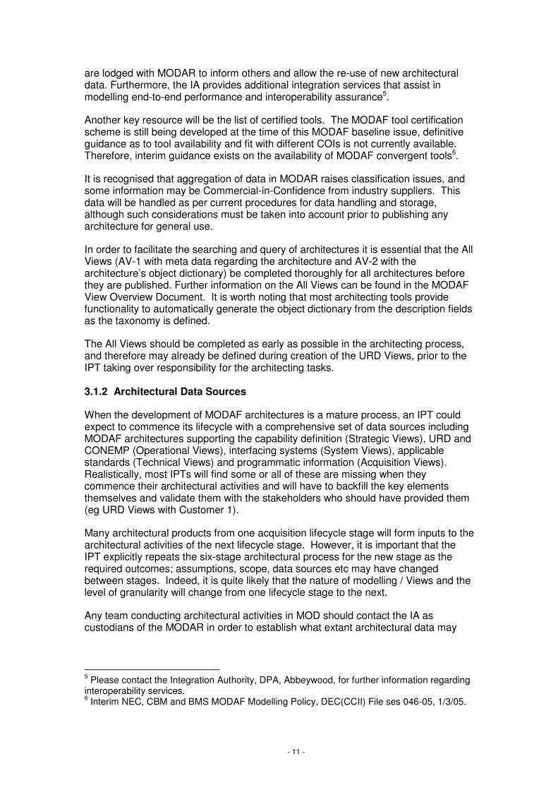
This Deskbook describes the architectural processes as they relate to the Acquisition community by reference to the Acquisition process model shown in Figure 3-2. This diagram also shows the key interfaces with the other communities considered within the MODAF Deskbooks. The interface documents are the focus of this diagram; the time element is not represented. The CADMID / CADMIT cycles are to represent acquisition as a whole and not intended to show exactly where the documents fit in to
- 14 -
a particular process stage. This type of information can be found on the Acquisition Management System (AMS)9.
Figure 3-2: Key Elements and Interfaces of Acquisition COI Processes
The Acquisition COI processes interface with all of the other COIs, some of the key inputs and outputs being:
• Concepts and Doctrine – inputs: provides the Acquisition processes with applied concepts that document the operational context and usage of the new capability
• Capability Management – inputs: is responsible for the CRD, URD, associated KURs and their management throughout the lifecycle
• Sustainment – outputs: the Acquisition processes deliver the operational capability and associated documentation to the Sustainment community, including the TLMP and MODAF architecture. In practice, the sustainment activities will normally be conducted by the same IPT as conducted the acquisition processes. There will be a progressive shift of focus as the capability moves from Manufacture into In-Service and the sustainment activities should be considered / planned for from the earliest stages of the CADMID cycle
• Customer 2 – inputs: the Capability Integration Plan (CIP) that defines responsibilities and integration mechanisms across all of the LoDs is developed in conjunction with Customer 2
9 MOD Smart Acquisition Management System http://www.ams.mod.uk
Acquisition
I T
DI
Concepts & Doctrine
Capability
Management
Operations
C A D M
C A D M
Acquisition
Project Management
Requirements
Systems / Technology
Industry
Through Life Management
URD SRD
CapabilityTLMP
CONOP,CONEMP,CONUSE CIP
- 15 -
The role of MODAF architectures in supporting the Acquisition COI processes and its key interfaces with the other COIs is described in the sections that follow, structured according to the main sub-processes shown in Figure 3-2.
3.3 Project Management
This section describes the use of MODAF for the Project Management workstream within the IPT. PRINCE2 is the Project Management methodology used by the MOD. MODAF is intended to support the use of PRINCE2 by standardising some of the information within the PRINCE2 deliverables, not to replace it as a methodology. The key Project Management activities, described in this section, which may be helped by use of MODAF are:
• Forming the IPT
• Systems Engineering Management Plan
• Initial Gate Review
• Management of Dependency Risks
• Main Gate Review
• Placing of contract(s) to meet the SRD
• Winding down the IPT
Figure 3-3 shows the key architectural product for Project Management, Acquisition View AcV-2 System of Systems Acquisition Programmes, and how this fits within the overall process, as shown in Figure 3-2.

- 16 -
Figure 3-3: Key MODAF Relationship to Project Management Activities
AcquisitionProject Management
Requirements
Systems / Technology
Industry
Through Life Management
CONCEPT ASSESSMENT DEMONSTRATION MANUFACTURE IN-SERVICE DISPOSAL
Form the IPT
URD
View Set
Essential View producedoutside this workstreamTV-1
InitialGate
Essential View producedby this workstream
Highly Desirable View producedby this workstream
Highly Desirable View producedoutside this workstream
TLMPAcV-2URD
SV-1OV-2
Managedependency
risks
OV-5StV-5
SRDURD
MainGate
SRD ITEAPTLMP
Placecontract(s) tomeet the SRD
SRD
URD
Wind down ofIPT
Key
TV-1
SV-1 TV-1OV-2
AcV-2

- 17 -
3.3.1 Form the IPT
The IPT may be formed through the Future Business Group (FBG) where the project scope does not match that of an existing IPT. Alternatively, a new system may be allocated to an existing IPT if it fits with that IPT’s current programme of work.
Any MODAF Views created relating to the system so far, as well as other supporting documentation, should be made available to the IPT from the relevant community. This may be Customer 1 with regard to the URD Views; in future it may be FBG or the System of Systems/Cluster Governance organisation (which is currently in development) that might provide Acquisition Views AcV-1 and AcV-2; AfNEC may also in future provide a new IPT with further information regarding the pre-Concept work relating to this system acquisition.
Part of this process includes co-ordination and management of the standards portfolio from System of Systems and URD requirements10. The use of the Technical Viewpoint, and TV-1 in particular, aids this role in tracking the Treaties, Legislation and Standards invoked.
TV-1 will increase in detail throughout CADMID cycle. The core constraints will be identified by Customer 1 in the URD, then the project specific constraints added through the SRD development work by Main Gate. It is expected that many of the core constraints within a capability’s TV-1 will be derived from the core set of the JSP 600 series which define the standards required to converge with DII and in the longer term towards NEC. During the Demonstration and Manufacture Stages, the standards may be refined further (through different, equivalent, standards being chosen and/or increasing in granularity) through contract negotiation and any proprietary standards from the preferred supplier. During the In-Service Stage the Sustainment community will also use and update the TV-1 where appropriate, through to Disposal, when legal or environmental standards may apply. Creation and maintenance of the TV-1 is an essential part of the Requirements process.
Figure 3-4: TV-1 Technical Standards Profile
10 Further information regarding Standardisation and its application to Acquisition can be found on the Acquisition Management System at http://www.ams.mod.uk/ams/content/topics/2616.htm, or by contacting PDG Standardisation.
Service Area Service System Elements
Standard / Policy
Data Transfer TCP/IP BOWMAN IP v6
Messaging Email BISA / Comms
MS Outlook CompliantJSP 324
Operating Systems
Workstations BISA / Control Stations
Data Interchange
Interoperability OMG XMI 2.1
Service Area Service System Elements
Standard / Policy
Data Transfer TCP/IP BOWMAN IP v6
Messaging Email BISA / Comms
MS Outlook CompliantJSP 324
Operating Systems
Workstations BISA / Control Stations
Data Interchange
Interoperability OMG XMI 2.1
Service AreaService AreaService Area ServiceServiceService System ElementsSystem
ElementsSystem
ElementsStandard / PolicyStandard / PolicyStandard / Policy
Data TransferData TransferData Transfer TCP/IPTCP/IPTCP/IP BOWMANBOWMANBOWMAN IP v6IP v6IP v6
MessagingMessagingMessaging EmailEmailEmail BISA / CommsBISA / CommsBISA / Comms
MS Outlook CompliantJSP 324
MS Outlook CompliantJSP 324
MS Outlook CompliantJSP 324
Operating SystemsOperating SystemsOperating Systems
WorkstationsWorkstationsWorkstations BISA / Control Stations
BISA / Control Stations
BISA / Control Stations
Data InterchangeData InterchangeData Interchange
InteroperabilityInteroperabilityInteroperability OMG XMI 2.1OMG XMI 2.1OMG XMI 2.1

- 18 -
3.3.2 Systems Engineering Management Plan
The Systems Engineering Management Plan (SEMP) forms one of the key project documents, along with the Through-life Management Plan (TLMP) and the Programme Management Plan (PMP).
The SEMP may make use of MODAF Views to illustrate the process to be used by the IPT in delivering the System. It will also record the Systems Engineering process to be followed by the IPT, and therefore, the Views that are planned for creation and analysis. An example of how MODAF Views can be used to illustrate the SEMP, and how the SEMP lays down the use of MODAF within the programme can be found in the Integration Authority SEMP Volume 111.
3.3.3 Initial Gate
The business case to be presented at Initial Gate includes the programme plan and costing for the procurement.
AcV-2, SoS Acquisition Programmes, shall be part of the Initial Gate business case, showing how the outline plan fits in with the delivery of related procurements to deliver the capability as a whole. AcV-2 is not designed to replace the usual Gantt Charts used by the project and programme managers. Rather, the Gantt charts will feed into the AcV-2, such that this View is a high-level summary of the more detailed information contained and managed within the usual Gantt charts. This will enable programmatic information to be presented to a senior audience in a standard format across IPTs. An example AcV-2 is shown in Figure 3-5.
11 Integration Authority Systems Engineering Management Plan Volume 1 – Systems Engineering Process. File name: SEMP vol 1 0.C_1.1_1.doc File ref: IA/06/02/2701

- 19 -
Figure 3-5: AcV-2 SoS Acquisition Programmes
The TLMP shall also inform the costing of the Initial Gate business case, along with its related Views (see Section 3.7 Through-Life Management).
Other Views that shall be used during the Initial Gate review are those that inform the URD (see Customer 1 Deskbook and URD Reference Guide for URD Development).
The overall submission for Initial Gate will be subjected to interoperability and compliance assurance by the IA so as to confirm that adequate consideration has been taken of interoperability issues (eg through Operational View OV-2 and System View SV-1) and compliance with standards including JSP 600 series (using TV-1). This assurance process will normally involve an assessment of the project’s MODAF architecture against those for interfacing systems held within MODAR.
3.3.4 Manage dependency risks
The Smart Acquisition Process refers to risk reduction across the whole procurement activity. Initially, the area where MODAF architectures can provide most assistance is in reducing dependency and interoperability risks.
AcV-2 SoS Acquisition Programmes identifies the main dependencies and timescales, including how the Defence Lines of Development (LoDs) are expected to develop and mature throughout the acquisition cycle. This maturity can be seen through the ‘traffic-light’ status assigned to each LoD, showing how the LoD is planned to mature. Early in the lifecycle, the LoD indicators are likely to be planned
Kestrel needs to come in to service as planned, to avoid a
capability gap arising when SPECS is fully disposed

- 20 -
to be Red or Amber, and as the project or programme moves through the CADMID lifecycle more LoD indicators will be planned to turn Green, as more of the LoDs mature through time. Using the information contained within this View, AcV-2 can be used to analyse the key programme dependency risks, including an assessment of the dependency risks associated with all LoDs.
OV-5 Operational Activity Model (from the URD) and StV-5 Capability to Systems Deployment Mapping (if available from Customer 1, if not the IPT might wish to obtain the relevant information themselves) can be useful to assess the effects of changing the scope of the required capability.
In terms of development risks, the URD and SRD (including their related Views) shall be the main inputs into risk reduction. This will be undertaken partly through the tender process. Depending on the acquisition, this process may take several months or years, during which time the solution and associated risk will be traded off in conjunction with the bidders (and ultimately the preferred bidder). The SO shall be involved with the drawing up of the Invitation To Tender (ITT) and any subsequent Tender Assessments to confirm these documents have the correct Standards Portfolio.
3.3.5 Main Gate
The Main Gate business case is a key deliverable, along with the SRD, from the Assessment Stage. The process and products are similar to those used at Initial Gate but with a higher degree of maturity expected at this stage. Specifically, the SRD, ITEAP and refined TLMP shall feed into this business case, along with the system design synthesis, to inform the decision on whether to proceed.
Again, the overall submission for Main Gate will be subjected to interoperability and compliance assurance by the IA so as to confirm that adequate consideration has been taken of interoperability issues (eg through OV-2 and SV-1) and compliance with standards including JSP 600 series (using TV-1)12. This assurance process will normally involve an assessment of the project’s MODAF architecture against those for interfacing systems held within MODAR.
Security accreditation may also be assessed during the Main Gate submission. Work is ongoing in the area of Information Assurance by DCSA and CSG, among others. The use of MODAF Views for security accreditation purposes is highly desirable, but the way forwards is yet to be agreed.
3.3.6 Place contract(s) to meet the SRD
The SRD forms a key part of the contract, laying down the requirements to be met by the supplier. Therefore, the URD and SRD Views (see sections 3.4.1 and 3.4.3) shall help to illustrate the requirements, and ensure that the IPT and the supplier share the same understanding of the wider capability and system interface requirements, as well as the system functional and performance requirements.
12 The interoperability and compliance assurance process is managed and implemented by IOCA (Interoperability Compliance Assurance). Please contact the IA for further information regarding IOCA assurance.

- 21 -
3.3.7 Wind down of IPT
The architectural element of closing down the IPT shall be to ensure that the final architecture description left after disposal of the system is reflected in MODAR, so that the repository reflects the removal of this system from service.

- 22 -
3.4 Requirements Management
This section describes the use of MODAF for the Requirements Management workstream within the IPT. The key activities for Requirements Management that may be helped by use of MODAF are:
• Develop and Maintain User Requirements Document (URD)
• Maintaining the linkage between User and System Requirements
• Develop and Maintain System Requirements Document (SRD)
• Integrated Testing, Evaluation and Acceptance Plan (ITEAP)
• Acceptance
Figure 3-6 shows the key architectural products for Requirements Management, within the URD and SRD, and how this fits within the overall process, as shown in Figure 3-2.

- 23 -
Figure 3-6: MODAF relationship to Requirements Management
AcquisitionProject Management
Requirements
Systems / Technology
Industry
Through Life Management
CONCEPT ASSESSMENT DEMONSTRATION MANUFACTURE IN-SERVICE DISPOSAL
View Set
Essential View producedoutside this workstream
Essential View producedby this workstream
Highly Desirable View producedby this workstream
Highly Desirable View producedoutside this workstream
Key
User Requirements Document (URD)
StV-6
OV-1
OV-2
OV-2
OV-3
OV-5
TV-1
OV-3
OV-5
TV-1
Linkage between user andsystem requirements SV-5
SV-4
OV-5
System Requirements Document (SRD)URD
SV-1
SV-2
SV-3
SV-4
SV-6
SV-7
TV-1
NB: The TV-1 contained inthe SRD will be at a lowerlevel than that in the URD.This more detailed TV-1 iscreated by the IPT, basedon the high-level TV-1 in
the URD.
SV-2
SV-6
SV-7
TV-1
Integrated Testing, Evaluation and AcceptancePlan
StV-2
OV-1c
SV-7
SV-3
SRD
OV-7 OV-7

- 24 -
3.4.1 User Requirements Document (URD)
The URD is owned and developed by the Customer 1 community. The finalised Equipment Programme (EP) is used as a basis for the selection and grouping of acquisition programmes. For these programmes, user requirement sets are developed and maintained throughout the acquisition process. The full Capability Management process, culminating in the URD production, is described in the Customer 1 Deskbook13 and the URD Reference Guide14. Other guides are also available15. The Views included in the URD, and provided by Customer 1 to the Acquisition Community, are shown in Figure 3-7 below.
Figure 3-7: URD MODAF Viewpoints through CADMID
Please refer to the Customer 1 Deskbook13 and the URD Reference Guide14 for further information regarding the URD creation process using MODAF.
3.4.2 Linkage between User and System Requirements
It is important to note that the use of these Views is not intended to duplicate or replace use of requirements management tools, such as DOORS. Rather, the use of SV-5 should complement the use of requirements management tools, acting as an ‘at-a-glance’ view of the information in the requirements tool. Several architecture tools are developing interfaces to requirements tools, so that the SV-5 can be automatically generated from the requirements mapping information.
The SV-5 shall be kept updated during SRD development to ensure the linkage with the URD Views is maintained16. SV-5 Operational Activity to Systems Function Traceability Matrix acts as the ‘glue’ between the URD and SRD Views. It is essential
13 MODAF-M10-001 14 MODAF-M10-003 15 For example, DCBM(Army) Guide to URD Development D CBM(A)/07/10/06 14 March 2005 16 As the Views are derived from the underlying data held in the model, the SV-5 should be automatically updated with any changes to underlying data resulting from changes to the URD or SRD.
IG MG
TV-1
OV-2
OV-1
OV-3
OV-5
Operational Viewpoint Suite
StV-6
OV-1
Operational Viewpoint Suite
OV-2
OV-1
Operational Viewpoint Suite
OV-5
TV-1
OV-3
OV-2
Assessment DemonstrationConcept
������������� ��
������������� ��
�
StV-6 StV-6
Essential View
Highly Desirable View

- 25 -
to show the operational activities laid down in the URD, and how these are met by the system functions required in the SRD. The SV-5 shall be kept up-to-date in parallel with development of the SRD, to ensure that the SRD Views are kept in-line with the URD Views.
It is also possible to link the functional decomposition in SV-4, Systems Functionality Description, (part of the SRD) with an allocation of functions to systems within the SV-5.
Figure 3-8: SV-5 links the URD and SRD
A high-level analysis of the OV-5, Operational Activity Model, may also be used to show the linkage between operational activities and the systems that support them.
3.4.3 System Requirements Document (SRD)
The Operational Views developed along with the URD during the Concept Stage help inform the development of the System Views and the associated System Requirements Document (SRD). A draft SRD is developed for Initial Gate, and the document is refined during the Assessment Stage, producing an agreed version at Main Gate. Figure 3-9 shows how the MODAF Views that support the SRD mature during the acquisition lifecycle.
Map to SV-4 System Functions
Operational Activities defined in URD
System Functions defined in SRD

- 26 -
Figure 3-9: SRD MODAF Viewpoints through CADMID
The System Requirements are developed from and must be traceable to the User Requirements; therefore, the main input to this process is the URD document and its related Views shown in Figure 3-7. StV-5 (if available) may also be useful in developing the SRD as an aid to identifying system options and interfaces.
The System Viewpoint is the key part of the SRD development. The first step is to derive those functions that need to be implemented within the system, through the essential SV-4 Systems Functionality Description. Analysis of the OV-5 in the URD will provide a key input to this process, to decide which activities are best supported by systems. The SV-5 shall show functional groupings that, depending on the size of the system, may be tendered for separately. It may also be used to identify the data flows required between functions, to enable closely coupled functions to be developed together. Creation of SV-4s requires detailed functional analysis and may usefully be supported by experimentation.
Figure 3-10: SV-4 Systems Functionality Description
IG MG
TV-1
SV-3
SV-1
System Viewpoint Suite
SV-6
TV-1
SV-2
Assessment DemonstrationConcept
SV-4
SV-7
SV-3
SV-1
System Viewpoint Suite
SV-4
SV-2
SV-6
SV-7
Essential View
Highly Desirable View
OV-7 OV-7

- 27 -
Interface requirements can now be documented. Prior to Main Gate, it is likely to be only the key external interfaces, which provide interoperability requirements, which will be modelled using the following essential Views:
• SV-1 Systems Interface Description shows the interfaces that the new system needs to support. It also shows the interdependencies with other systems (and therefore other IPTs and/or suppliers), with which the supplier of the new system will need to co-operate. Additionally, it shows the nodes to which the supplier needs to deliver systems, and supports an understanding of its fit within the Concept of Operations (ConOps) through identification of the information needlines
Figure 3-11: SV-1 Systems Interface Description
• SV-2 consists of several sub-Views, described below. These are all key Views to specify and assure interoperability between systems. These may be created at a summary level for the SRD, and then increased in detail by the supplier during their system design:
− SV-2a System Port Specification shows the network protocols at each layer of the network stack for each system port, to which the new system must conform
Figure 3-12: SV-2a System Port Specification
Needlines show interdependencies with other systems, with which the new
system will need to share information

- 28 -
− SV-2b System to System Protocol Stack is used to assess the compatibility of the protocol stacks between multiple interfacing systems in order to provide interoperability assurance
Figure 3-13: SV-2b System-to-System Protocol Stack
− SV-2c System Connectivity Clusters shows how the individual interfaces required can be logically grouped into nodal connections, to identify redundancy in the system of systems, and to reduce the number of point-to-point connections that need to be maintained (thereby reducing maintenance and support costs). This View can be used to assess network performance needs.
Figure 3-14: SV-2c System Connectivity Clusters
• SV-3 System to System Matrix identifies which of the potential communications paths shown graphically in SV-1 form the key system to system interfaces, presenting them in a matrix format to identify all required interfaces

- 29 -
Figure 3-15: SV-3 System-to-System Matrix
• SV-6 Systems Data Exchange Matrix shows the characteristics of the data that will be sent over the interface connections identified in SV-1 and SV-3. This enables network capacity analysis to ensure that the network will have the required bandwidth available to support these interface requirements and may be used to support the development of the system data models. The SV-2 suite of Views will also assist with network analysis activities. The SV-6 should be related to the Information Exchange Requirements laid down in the URD, in OV-3. Again, it is likely that this will be developed by the customer at a high-level within the SRD, and increased in granularity by the supplier during system design.
Figure 3-16: SV-6 Systems Data Exchange Matrix
It should be noted that the development of all of these Views regarding interfacing systems and interoperability will be supported by information on interfacing systems that will be available through MODAR. The IA also provides related services to help develop interoperability requirements.
The performance requirements for each part of the system are then defined in an essential SV-7 Systems Performance Parameters Matrix.
The OV-7 Logical Data Model may need to be developed to reflect the increased level of detail regarding the data and information exchanges emerging during the SRD development, although this is not essential. This is preferable to the creation of

- 30 -
an SV-11 Physical Schema, as the physical schema should be part of the solution design, not the requirements. Please refer to the MODAF View Overview Document for further information regarding these Views.
Finally, refining the TV-1 is essential during SRD development to define the system constraints and to ensure the system conforms to the standards and protocols that will enable interoperability. TV-2, Technical Standards Forecast, may also be updated with new information regarding upcoming standards and protocols. In the future it may be that a family of over-arching TV-1s and TV-2s will be maintained by the appropriate authorities within MOD (for example: an IT TV-1, a health & safety TV-1, a building materials TV-1 etc), from which an IPT will be able to cherry-pick the standards and constraints relevant to their system. Initially, however, IPTs will need to develop their own Technical Views, building on those included in the URD.
The SRD will continue to be updated throughout the CADMID cycle, as trade-offs are undertaken, and the system design matures. The implications of any trade-offs need to be traced all the way up from Systems (through the SRD Views) through the Operational Views (in the URD), up to the effect on the Capability delivery (through the Strategic Views in the Capability Area Plan (CAP)). The Strategic Views StV-2 and StV-3 (where available from Customer 1), should therefore be used in conjunction with the URD and SRD when performing trade-offs. This is done to ensure that when a system trade-off is made, the implications at both Operational and Strategic levels are considered, so that key requirements and constraints are not violated.
3.4.4 Integrated Testing, Evaluation and Acceptance
This section describes the MODAF Views that provide assistance in planning the Test, Evaluation and Acceptance of the System and Capability.
MODAF architectures are particularly suited to the development of Validation and Verification (V&V) Requirements for the ITEAP, by providing the Views that might be used as ‘checklists’ during testing, evaluation and acceptance. Although the ITEAP is intended to support test and evaluation conducted during Demonstration and Manufacture stages it is important that its production and refinement is commenced as early as possible in the CADMID cycle. It will be useful to liase with the IA when developing the ITEAP so as to establish the nature of the test and evaluation facilities that are likely to be available at the time the new capability is likely to commence testing and to synchronise its test and evaluation programme with other relevant systems.
StV-2 Capability Taxonomy (with performance attributes added17) and OV-1c Operational Performance Attributes will both provide sources of acceptance criteria for inclusion within the ITEAP. Both these Views are essential for creation by Customer 1, and so shall be included in the ITEAP as long as they are available.
17 Performance Attributes may be added to a Capability in the MODAF Meta-Model for this View. These may be displayed on the main View or in tabular format as an appendix to the View if they would over-complicate the main View purpose. Please refer to the MODAF Technical Handbook (MODAF-M07-022) for further information regarding Capability attributes.

- 31 -
SV-7 System Performance Parameters Matrix (which forms part of the SRD document suite) is also essential for inclusion in the ITEAP, to identify the performance characteristics against which the system will be accepted.
SV-3 Systems-Systems Matrix may be useful as an ‘at-a-glance’ view of all the systems to which the new system should interface, which can be checked during testing.
In addition, any of the SRD Views may be used as the basis for the V&V Requirements in developing the ITEAP.

- 32 -
3.5 Systems / Technology
This section describes the use of MODAF for the Systems / Technology workstream within the IPT. The key activities for the Systems / Technology workstream that may be helped by use of MODAF are:
• Identification of technology and procurement options
• Demonstration of the ability to deliver integrated capability
• Technology insertion (during the In-Service Stage)
Figure 3-17 shows the key architectural products for the Systems / Technology workstream, and how this fits within the overall process, as shown in Figure 3-2.

- 33 -
Figure 3-17: MODAF Relationship to System / Technology workstream
AcquisitionProject Management
Requirements
Systems / Technology
Industry
Through Life Management
CONCEPT ASSESSMENT DEMONSTRATION MANUFACTURE IN-SERVICE DISPOSAL
View Set
Essential View producedoutside this workstream
Essential View producedby this workstream
Highly Desirable View producedby this workstream
Highly Desirable View producedoutside this workstream
Key
Identify technology and procurement options
StV-3
TV-1
SV-9
TV-2
SV-9
TV-2
updated
updated
Demonstrate ability to deliverintegrated capability
OV-2
OV-3
SV-1
SV-7
SV-6
OV-1c
SV-7
Technology insertion
SV-9
TV-2
- 34 -
3.5.1 Identify technology and procurement options
The undertaking of this process described here relates to the current CADMID process. It is understood that this is subject to change with the AfNEC (Acquisition for NEC) work, looking at use of alternative procurement and delivery options (such as more off-the-shelf (OTS) and re-use of existing systems to deliver additional capability). When purchasing Commercial OTS (COTS) equipment it is important not to over-specify the standards – or else additional cost and risk may be transferred back to MOD, negating the benefits of using a COTS solution.
StV-3 Capability Phasing, provided by Customer 1, shows the IPT the broader picture of the overall capability delivery and which other systems are being acquired, upgraded or retired in the time period that the new capability is being procured. This may help inform decisions regarding common technologies and procurement options across a number of related capabilities, such as applications delivering in the same epoch agree on a common target Operating System between themselves.
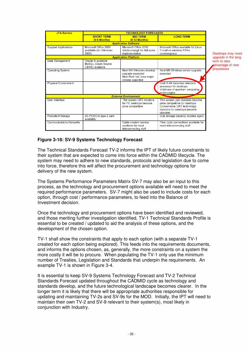
SV-9, Technology Forecast, informs the IPT of new technology that may become available in the short-, medium- and long-term. If new technology is due to become available during the lifetime of the acquisition process, this will need to be considered as an option. The technology forecast also helps the IPT to avoid technology and system options that would be obsolete by the time the system is put into service. An example SV-9 can be found in Figure 3-1818.
18 Note that the time-periods defined in the example View shown here are representative only. Any timeframe may be defined for the short, medium and long term depending on the overall timeframe for the architecture. The same is true for the timeframes used within the TV-2 View.
- 35 -
Figure 3-18: SV-9 Systems Technology Forecast
The Technical Standards Forecast TV-2 informs the IPT of likely future constraints to their system that are expected to come into force within the CADMID lifecycle. The system may need to adhere to new standards, protocols and legislation due to come into force, therefore this will affect the procurement and technology options for delivery of the new system.
The Systems Performance Parameters Matrix SV-7 may also be an input to this process, as the technology and procurement options available will need to meet the required performance parameters. SV-7 might also be used to include costs for each option, through cost / performance parameters, to feed into the Balance of Investment decision.
Once the technology and procurement options have been identified and reviewed, and those meriting further investigation identified, TV-1 Technical Standards Profile is essential to be created / updated to aid the analysis of these options, and the development of the chosen option.
TV-1 shall show the constraints that apply to each option (with a separate TV-1 created for each option being explored). This feeds into the requirements documents, and informs the options chosen, as, generally, the more constraints on a system the more costly it will be to procure. When populating the TV-1 only use the minimum number of Treaties, Legislation and Standards that underpin the requirements. An example TV-1 is shown in Figure 3-4.
It is essential to keep SV-9 Systems Technology Forecast and TV-2 Technical Standards Forecast updated throughout the CADMID cycle as technology and standards develop, and the future technological landscape becomes clearer. In the longer term it is likely that there will be appropriate authorities responsible for updating and maintaining TV-2s and SV-9s for the MOD. Initially, the IPT will need to maintain their own TV-2 and SV-9 relevant to their system(s), most likely in conjunction with Industry.
Desktops may need upgrade in the long term to take advantage of new processors

- 36 -
3.5.2 Demonstrate ability to deliver integrated capability
Once the option has been chosen during the Concept and Assessment Stages, it must be shown to deliver the requirements during the Demonstration Stage. The following Views will support technology demonstrators / prototypes in demonstrating that the requirements are met by the chosen system solution.
OV-2 Operational Node Connectivity Description and SV-6 Systems Data Exchange Matrix shows how the system will meet the interoperability requirements, to provide an integrated capability.
OV-3 Operational Information Exchange Matrix and SV-1 Systems Interface Description respectively show the Information Exchange Requirements (IERs), which should be included in the contract to ensure integration, and the physical systems that will need to be connected to meet these IERs.
OV-1c Operational Performance Parameters and SV-7 System Performance Parameters Matrix show the required operational and system performance to be delivered by the solution.
3.5.3 Technology insertion
Once the system is in the In-Service Stage, the technology evolution and evolving standards may drive obsolescence of system elements. The TLMP will be updated using inputs from the SV-9 and TV-2 to reflect this changing technology landscape, and upgrades, improvements or replacement initiated through Customer 1 to the IPT as needed.

- 37 -
3.6 Industry / Suppliers
This section describes the use of MODAF for the Industry / Supplier liaison within the IPT. The key activities for the Industry / Suppliers in conjunction with the IPT that may be helped by use of MODAF are:
• Industry involvement
• System synthesis
• Contract negotiation
• Solution delivery
• Carrying out any agreed upgrades or improvements once the system is in the In-Service Stage
Figure 3-19 shows the key architectural products for the Industry / Supplier liaison, and how this fits within the overall process, as shown in Figure 3-2.

- 38 -
Figure 3-19: MODAF Relationship to Industry workstream
AcquisitionProject Management
Requirements
Systems / Technology
Industry
Through Life ManagementCONCEPT ASSESSMENT DEMONSTRATION MANUFACTURE IN-SERVICE DISPOSAL
View Set
Essential View producedoutside this workstream
Essential View producedby this workstream
Highly Desirable View producedby this workstream
Highly Desirable View producedoutside this workstream
Key
Involve Industry
OV-1
OV-2
System SynthesisSV-9
TV-2
SRD
Negotiate Contract
URD
SRD
Deliver Solution
Carry out any agreedupgrades or improvements
StV-2
StV-3
SV-8

- 39 -
3.6.1 Involve Industry
The MOD Defence Industrial Policy (2002) provides the framework for MOD’s relationship with the defence industry. It makes clear that, right from the start of acquisition projects, MOD is being more transparent about the factors that affect acquisition decisions. MODAF can play a significant role in this transparency by providing early and clear visibility of the context, constraints and interfaces of the required new capability. As far as possible, these will be made clear to potential bidders at the outset to enable them to frame their bids accordingly. This section describes the Views that are useful in early Industry involvement, should an IPT wish to engage with Industry during the early Stages of Acquisition.
Engaging industry during the first stages of the project cycle is important, for example by seeking industry’s views on initial procurement strategies and their help during the early stages of an evolving requirement.
The Operational Viewpoint is particularly useful in the initial engagement with Industry in identifying the operational context and use cases for the new capability.
OV-1 and OV-2 (where available from Customer 1) shall be used for industry involvement during the Concept Stage.
Customer 1 provides the OV-1 within the URD. It gives the high-level background to the system, as shown in Figure 3-20, Figure 3-21 and Figure 3-22 below. The Concepts and Doctrine Community provides the ConOps, ConEmp and ConUse, which can also be used with Industry during this process.
Figure 3-20: OV-1a High Level Operational Graphic
- 40 -
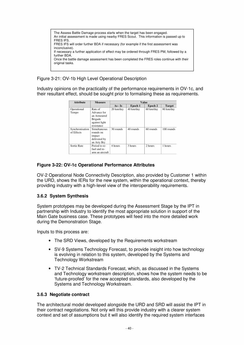
Figure 3-21: OV-1b High Level Operational Description
Industry opinions on the practicality of the performance requirements in OV-1c, and their resultant effect, should be sought prior to formalising these as requirements.
Figure 3-22: OV-1c Operational Performance Attributes
OV-2 Operational Node Connectivity Description, also provided by Customer 1 within the URD, shows the IERs for the new system, within the operational context, thereby providing industry with a high-level view of the interoperability requirements.
3.6.2 System Synthesis
System prototypes may be developed during the Assessment Stage by the IPT in partnership with Industry to identify the most appropriate solution in support of the Main Gate business case. These prototypes will feed into the more detailed work during the Demonstration Stage.
Inputs to this process are:
• The SRD Views, developed by the Requirements workstream
• SV-9 Systems Technology Forecast, to provide insight into how technology is evolving in relation to this system, developed by the Systems and Technology Workstream
• TV-2 Technical Standards Forecast, which, as discussed in the Systems and Technology workstream description, shows how the system needs to be ‘future-proofed’ for the new accepted standards, also developed by the Systems and Technology Workstream.
3.6.3 Negotiate contract
The architectural model developed alongside the URD and SRD will assist the IPT in their contract negotiations. Not only will this provide industry with a clearer system context and set of assumptions but it will also identify the required system interfaces
Attribute Measure Value As - Is Epoch 1 Epoch 2 Target Operational Tempo
Rate of Advance for an Armoured Brigade against light resistance
20 km/day 40 km/day 60 km/day 80 km/day
Synchronisation of Effects
Simultaneous rounds on impact delivered by an Arty Bty
30 rounds 40 rounds 60 rounds 100 rounds
Sortie Rate Period to re-fuel and re-arm an aircraft
4 hours 3 hours 2 hours 1 hours
The Assess Battle Damage process starts when the target has been engaged. An initial assessment is made using nearby FRES Scout. This information is passed up to FRES IFS. FRES IFS will order further BDA if necessary (for example if the first assessment was inconclusive). If necessary a further application of effect may be ordered through FRES PM, followed by a further BDA. Once the battle damage assessment has been completed the FRES roles continue with their original tasks.

- 41 -
and standards. Furthermore, the boundaries within which system elements can be traded-off will be apparent. During negotiations, the cost and time implications of the architectural components can also be finalised, and used as a basis for updating the TLMP with more detailed plans.
3.6.4 Deliver the solution
The supplier will have responsibility to deliver the solution in accordance with the contract and SRD. As part of the solution delivery, the supplier will find it helpful to use some of the MODAF Views as part of their detailed design work.
3.6.5 Carry out any agreed upgrades or improvements
Upgrades and improvements are identified by Customer 2, and fed back into the EP for management by Customer 1. These will usually spawn a new CADMID cycle within the responsible IPT and, as such, will utilise the same MODAF Views as described in this Deskbook.
The need for upgrades or improvements are also informed by the following: StV-2, Capability Functions; StV-3, Capability Phasing, (both of which are owned and updated by the Customer 1 function); and SV-8, the Systems Evolution Description, essential in the TLMP, that shows the planned upgrade path for the system.

- 42 -
3.7 Through-Life Management
This section describes the use of MODAF for Through-Life Management within the IPT. The key activities for Through-Life Management that may be helped by use of MODAF are:
• Through-Life Management Planning (TLMP)
• Integrated Logistics Support
Figure 3-23 shows the key architectural products for Through-Life Management, and how this fits within the overall process, as shown in Figure 3-2.

- 43 -
Figure 3-23: MODAF Relationship to Through-Life Management
AcquisitionProject Management
Requirements
Systems / Technology
Industry
Through Life Management
CONCEPT ASSESSMENT DEMONSTRATION MANUFACTURE IN-SERVICE DISPOSAL
View Set
Essential View producedoutside this workstream
Essential View producedby this workstream
Highly Desirable View producedby this workstream
Highly Desirable View producedoutside this workstream
Key
Through-Life Management Plan
SV-9
SV-8
AcV-2
SV-8
TV-2
TV-1
Integrated Logistic Support
OV-1c
NB: An OV-1c for the entire system will be produced byCustomer 1 within the URD. The Through-Life Management
workstream creates an instance of OV-1c pertaining tosustainability, maintainability etc of the system
OV-5
- 44 -
3.7.1 TLMP
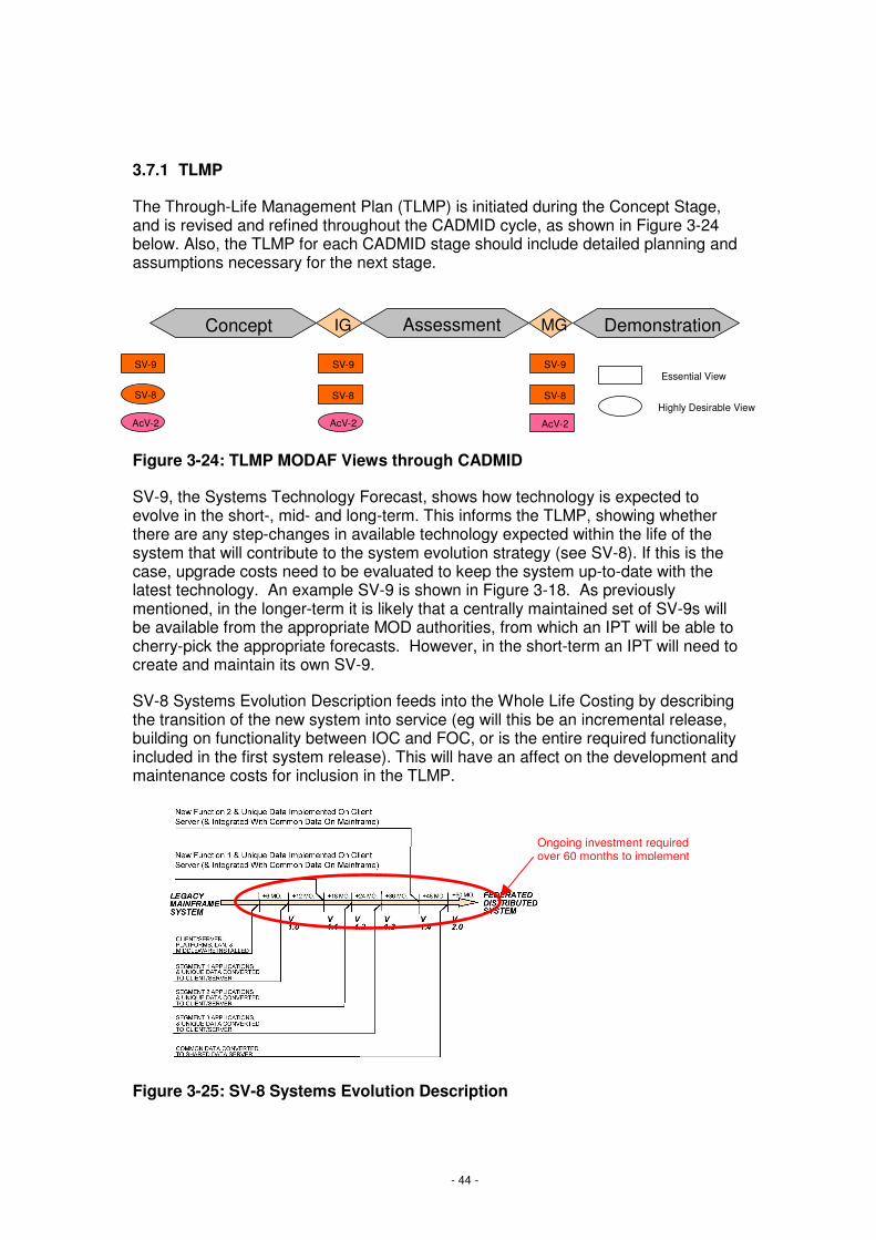
The Through-Life Management Plan (TLMP) is initiated during the Concept Stage, and is revised and refined throughout the CADMID cycle, as shown in Figure 3-24 below. Also, the TLMP for each CADMID stage should include detailed planning and assumptions necessary for the next stage.
Figure 3-24: TLMP MODAF Views through CADMID
SV-9, the Systems Technology Forecast, shows how technology is expected to evolve in the short-, mid- and long-term. This informs the TLMP, showing whether there are any step-changes in available technology expected within the life of the system that will contribute to the system evolution strategy (see SV-8). If this is the case, upgrade costs need to be evaluated to keep the system up-to-date with the latest technology. An example SV-9 is shown in Figure 3-18. As previously mentioned, in the longer-term it is likely that a centrally maintained set of SV-9s will be available from the appropriate MOD authorities, from which an IPT will be able to cherry-pick the appropriate forecasts. However, in the short-term an IPT will need to create and maintain its own SV-9.
SV-8 Systems Evolution Description feeds into the Whole Life Costing by describing the transition of the new system into service (eg will this be an incremental release, building on functionality between IOC and FOC, or is the entire required functionality included in the first system release). This will have an affect on the development and maintenance costs for inclusion in the TLMP.
Figure 3-25: SV-8 Systems Evolution Description
Ongoing investment required over 60 months to implement
IG MG
SV-9
AcV-2
SV-8
Assessment DemonstrationConcept
SV-9
SV-8
AcV-2
SV-9
SV-8
AcV-2
Essential View
Highly Desirable View

- 45 -
The TLMP also contains the detailed plans for the current phase. The AcV-2 SoS Acquisition Programmes View shall therefore be refined as part of this planning activity. Figure 3-5 shows an example AcV-2.
The TLMP is revised throughout the CADM stages as the solution, and therefore cost for development, support and upgrades, is defined in increasing granularity. As the industry supplier becomes more involved during the Demonstration and Manufacture Stages, the TLMP should be updated in consultation with the Industry supplier.
The TLMP shall also need to make reference to appropriate elements of the TV-1 and TV-2 that specify or forecast the regulations that are likely to apply to an equipment’s ultimate decommissioning and disposal. This is becoming increasingly important as more environmental legislation is being introduced and the hazards associated with more materials and processes are being highlighted.
The TLMP is closely related to the Capability Integration Plan (CIP), produced by Customer 2. The IPT should liase with the relevant Customer 2 to ensure that this integration occurs between the TLMP and CIP. The Customer 2 Deskbook (MODAF-M10-005) contains further information regarding the Views contained within the Capability Integration Plan.
3.7.2 Integrated Logistic Support
The focus on ILS begins during the Demonstration Stage (though time and effort is expended on Whole Life Costing (WLC) prior to both initial and main gates, when options for support solutions must be considered) and ILS work continues throughout CADMID. OV-1c Operational Performance Attributes is essential for use to articulate the availability, sustainability, reliability and maintainability of the system.
Figure 3-26: OV-1c Operational Performance Attributes
OV-5 Operational Activity Model, from the URD, informs the ILS approach.
For further activity on how MODAF supports the TLMP and ILS once they are actioned during the In-Service Stage, please refer to the Sustainment Deskbook (MODAF-M10-014).
- 46 -
4. Worked Example
This section describes a worked example of the Acquisition process as described in Section 3. The example illustrated is based in the ISTAR community, and its level of complexity is simplified in order to avoid the need to understand specific ISTAR systems and technologies. The example does not represent the UK's ISTAR assets; it contains a number of fictional systems and entities.
A similar ISTAR example has been replicated in each of the COI Deskbooks to provide a common thread of understanding across business functions and processes. This approach has been selected to demonstrate MODAF's ability to integrate people, processes, organisations, systems and equipments across the MOD.
It is envisaged that this section will be expanded to include further examples from the Acquisition Community as MODAF becomes more widely used, and so an increasing number of examples become available upon which to draw.
An additional worked example from the FRES IPT can be found in the Restricted Annex to this Deskbook (MODAF-M10-014).
4.1 ISTAR Worked Example Introduction
The ISTAR Worked Example for Acquisition begins at the point of forming the IPT. Customer 1 has completed their Capability Audit and reviewed the Capability Options. The Option chosen to fill an identified gap within the ISTAR Capability is to procure two new ISTAR assets, SPECS 2 and KESTREL. Separate IPTs are being established, one to procure KESTREL and the other to procure SPECS 2. This worked example follows the architecture work undertaken by the SPECS 2 IPT.
4.2 Project Management
4.2.1 Form the IPT
The SPECS 2 IPT is formed through the Future Business Group (FBG), and is provided with an initial AcV-2 developed by Customer 1 as part of their Capability Options planning:

- 47 -
Figure 4-1: AcV-2 provided by Customer 119
From the System of Systems and URD requirements there are certain standards that constrain the SPECS 2 IPT from the outset. These are collated in an initial TV-1 to set the boundaries for the IPT’s activities:
Figure 4-2: Initial TV-1 setting the standards and constraints for the IPT
4.2.2 Systems Engineering Management Plan
It can be seen from the standards in the initial TV-1 that the Systems Engineering Management Plan (SEMP) is a key document for the IPT to produce. This is begun
19 This AcV-2 shows 6 lines of development – the MODAF meta-model allows any number of lines of development to be included within the data for this View to accommodate the new 8 LoDs, or any additional future LoDs
ISTAR SYSTEMS
SPECS
DISP START
LOOKER
DISP START DISP FIN
NEMESIS
DISP START
People
Organisation
Sustainment
Equipment Training
Doctrine
LoDs
Pre-IG
IG to MG
MG to IOC
IOC to FOC
In Service
Disposal
Key to View
Project Phase
No outstanding issues
Manageable issues
Critical issues
LoD 'Hexagon'
2005 2020 2040
DISP FIN
SPECS 2
KESTREL
MOD Sustainment guidelinesSPECS 2 and DLoD support
Ability to sustain capability
Sustainment & Logistics
US Guidance NotesSPECS 2 external US communication network interfaces
Communications/Networking
US Interoperability
MOD Systems Engineering Management Plan (SEMP)
SPECS 2 & interfacesSystems Engineering
MOD Strategy
ISTAR Acceptance ProcedureAll fielded capabilityAcceptance
SOPsAll fielded capabilityOperationsISTAR Governance
Standard/ PolicyApplicable ElementsServiceService Area

- 48 -
during Concept, and will be updated and maintained throughout the CADMID lifecycle for the SPECS 2 system. During the IPT formation, the SEMP lays down how the IPT will be organised, including (amongst other things20) which MODAF Views the IPT intends to use for the analysis and design of the SPECS 2 system.
4.2.3 Initial Gate
At Initial Gate, the SPECS 2 Programme Manager will collate the SPECS 2 Business Case, containing the AcV-2 shown in Figure 4-1 and the TV-1 shown in Figure 4-2, along with the TLMP (see Through-Life Management Section 4.6) and the URD validation Views (or actual URD Views if available, see Requirements Management Section 4.3).
4.2.4 Manage Dependency Risks
As mentioned in the introduction to this worked example, the introduction of SPECS 2 is one part of the Capability deployment that includes the introduction of another ISTAR asset, KESTREL. There are therefore dependencies between the introduction of SPECS 2 and KESTREL, as without one or other being delivered into service, the required Capability will not be available.
The AcV-2 allows the IPT Programme Manager to monitor delivery timescales in conjunction with the other related deliveries, to monitor whether all the dependencies are on-track to deliver in conjunction with the SPECS 2 delivery.
20 For more information regarding the contents of a SEMP, an example can be found in the Integration Authority Systems Engineering Management Plan Volume 1 – Systems Engineering Process. File name: SEMP vol 1 0.C_1.1_1.doc File ref: IA/06/02/2701
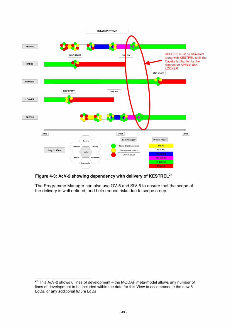
- 49 -
Figure 4-3: AcV-2 showing dependency with delivery of KESTREL21
The Programme Manager can also use OV-5 and StV-5 to ensure that the scope of the delivery is well defined, and help reduce risks due to scope creep.
21 This AcV-2 shows 6 lines of development – the MODAF meta-model allows any number of lines of development to be included within the data for this View to accommodate the new 8 LoDs, or any additional future LoDs
ISTAR SYSTEMS
SPECS
DISP START
LOOKER
DISP START DISP FIN
NEMESIS
DISP START
People
Organisation
Sustainment
Equipment Training
Doctrine
LoDs
Pre-IG
IG to MG
MG to IOC
IOC to FOC
In Service
Disposal
Key to View
Project Phase
No outstanding issues
Manageable issues
Critical issues
LoD 'Hexagon'
2005 2020 2040
DISP FIN
SPECS 2
KESTREL
SPECS 2 must be delivered along with KESTREL to fill the Capability Gap left by the disposal of SPECS and LOOKER

- 50 -
Figure 4-4: OV-5 from the URD
OV-5 is part of the User Requirements Document, delivered before Main Gate submission. It clearly lays out the operational activities that SPECS 2 must support. Any request to support additional activities can be referred back to this View, and shown to be changes to the original scope.
Similarly StV-5, where available, shows the Capability gap being addressed by SPECS 2, as well as its intended implementation time frame. Any request to address other Capability gaps through delivery of SPECS 2 will also be changes to the original scope.
Figure 4-5: StV-5 showing the Capability gap to be addressed
Request SPECS 2 beprepared for Recce
of target area
Request launch ofSPECS 2
PJHQ BDE HQ ISTAR BASE STATION SPECS 2
Execute SPECS 2launch procedure
Provide suspectedtarget location
Provide SPECS 2search area co-
ordinates
Configure SPECS 2to provide video
footage/ data reports
Provide preferredtarget information
requirements
Request SPECS 2provide live video
footage/ data reports
Enter SPECS 2search area flight
profile
Moves to searcharea flight profile
Take off
Captures/ fuses livevideo footage/ data
reports
Relay video footage/data reportsProvide target status
Decide whether totake action
Strategic - PJHQ
Operational -JFHQ
Tactical -Brigade
Tactical - SpecialForces
InformationAcquistion
InformationManagement Effects
BISA
NEMESISSPECS
MILAN
CR2
FGA
EPOCH 1
LOOKER
Strategic - PJHQ
Operational -JFHQ
Tactical -Brigade
Tactical - SpecialForces
InformationAcquistion
InformationManagement Effects
BISA
NEMESIS
CR2
FGA
EPOCH 2
Strategic - PJHQ
Operational -JFHQ
Tactical -Brigade
Tactical - SpecialForces
InformationAcquistion
InformationManagement Effects
BISA
CR2
FGA
EPOCH 3
Any requests to fulfil requirements outside of the Information Acquisition Capability are changes to scope
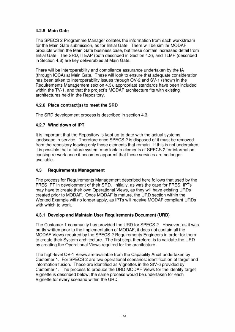
- 51 -
4.2.5 Main Gate
The SPECS 2 Programme Manager collates the information from each workstream for the Main Gate submission, as for Initial Gate. There will be similar MODAF products within the Main Gate business case, but these contain increased detail from Initial Gate. The SRD, ITEAP (both described in Section 4.3), and TLMP (described in Section 4.6) are key deliverables at Main Gate.
There will be interoperability and compliance assurance undertaken by the IA (through IOCA) at Main Gate. These will look to ensure that adequate consideration has been taken to interoperability issues through OV-2 and SV-1 (shown in the Requirements Management section 4.3), appropriate standards have been included within the TV-1, and that the project’s MODAF architecture fits with existing architectures held in the Repository.
4.2.6 Place contract(s) to meet the SRD
The SRD development process is described in section 4.3.
4.2.7 Wind down of IPT
It is important that the Repository is kept up-to-date with the actual systems landscape in-service. Therefore once SPECS 2 is disposed of it must be removed from the repository leaving only those elements that remain. If this is not undertaken, it is possible that a future system may look to elements of SPECS 2 for information, causing re-work once it becomes apparent that these services are no longer available.
4.3 Requirements Management
The process for Requirements Management described here follows that used by the FRES IPT in development of their SRD. Initially, as was the case for FRES, IPTs may have to create their own Operational Views, as they will have existing URDs created prior to MODAF. Once MODAF is mature, the URD section within the Worked Example will no longer apply, as IPTs will receive MODAF compliant URDs with which to work.
4.3.1 Develop and Maintain User Requirements Document (URD)
The Customer 1 community has provided the URD for SPECS 2. However, as it was partly written prior to the implementation of MODAF, it does not contain all the MODAF Views required by the SPECS 2 Requirements Engineers in order for them to create their System architecture. The first step, therefore, is to validate the URD by creating the Operational Views required for the architecture.
The high-level OV-1 Views are available from the Capability Audit undertaken by Customer 1. For SPECS 2 are two operational scenarios: identification of target and information fusion. These are identified as Vignettes in the StV-6 provided by Customer 1. The process to produce the URD MODAF Views for the identify target Vignette is described below; the same process would be undertaken for each Vignette for every scenario within the URD.
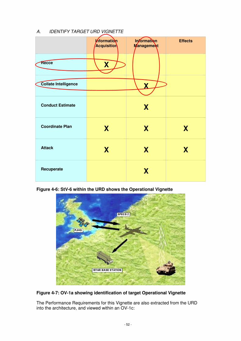
- 52 -
A. IDENTIFY TARGET URD VIGNETTE
Figure 4-6: StV-6 within the URD shows the Operational Vignette
Figure 4-7: OV-1a showing identification of target Operational Vignette
The Performance Requirements for this Vignette are also extracted from the URD into the architecture, and viewed within an OV-1c:
Information Acquisition
Information Management
Effects
Recce X
Collate Intelligence X
Conduct Estimate X
Coordinate Plan X X X
Attack X X X
Recuperate X
Information AcquisitionInformation AcquisitionInformation Acquisition
Information ManagementInformation
ManagementInformation
ManagementEffectsEffectsEffects
RecceRecceRecce XXX
Collate IntelligenceCollate IntelligenceCollate Intelligence XXX
Conduct EstimateConduct EstimateConduct Estimate XXX
Coordinate PlanCoordinate PlanCoordinate Plan XXX XXX XXX
AttackAttackAttack XXX XXX XXX
RecuperateRecuperateRecuperate XXX

- 53 -
Figure 4-8: OV-1c showing Performance Requirements
The SPECS 2 Requirements Manager then decided to break down the Vignettes further through the creation of textual use cases for each scenario. These create a hybrid OV-1b, using use case documents containing richer information than a standard OV-1b:
Overview To identify the target, PJHQ directly task SPECS 2 to identify the target. SPECS 2, having then identified the target returns the identification data to both PJHQ and the common base station.
Primary Actors PJHQ
Supporting Actors
SPECS 2
ISTAR Base Station
Trigger PJHQ requests SPECS 2 be prepared for Recce of target area.
Preconditions Precondition
1 PJHQ executes SPECS 2 launch procedure.
Scenario Step
1 SPECS 2 takes off.
2 PJHQ provides SPECS 2 with search area co-ordinates.
3 PJHQ enters SPECS 2 search area flight profile.
4 SPECS 2 moves to search area flight profile.
5 PJHQ requests SPECS 2 identifies target.
15510152530Maximum time delay (seconds) viewing tasked location
SPECS 2 Video Delay
55567810Number of days required for maintenance
SPECS 2 Downtime
6444422Number of individual video channels provided
SPECS 2 Video Support
300
24
2027
300
36
2028
500
36
2029
600
36
2030
SPECS 2 Range
SPECS 2 Flight Time
Attribute
300
24
2026
1200300Maximum number of km from ISTAR base station
4824Maximum number of hours for a single flight
Target2025Measure

- 54 -
6 PJHQ configures SPECS 2 to identify target.
7 SPECS 2 captures target video and data.
8 SPECS 2 relays video footage and data reports to PJHQ and
ISTAR Base Station.
9 PJHQ analyses video and data
10 ISTAR Base Station stores the video and data.
Postconditions Post condition
1 PJHQ decides whether to take action.
Extensions
Variations SPECS 2 could not perform operation so other ISTAR or organic assets are tasked.
Candidate Requirements
Remarks
Figure 4-9: Use Case document used as a hybrid OV-1b
The use case is then broken down into an OV-5 Operational Activity Model, taking the scenario steps above, and laying them over the organisations that undertake each step in the process:
Figure 4-10: OV-5 derived from Use Case document
Request SPECS 2 beprepared for Recce
of target area
PJHQ ISTAR BASE STATION SPECS 2
Execute SPECS 2launch procedure
Configure SPECS 2to identify target
Enter SPECS 2search area flight
profile
Moves to searcharea flight profile
Take off
Captures targetvideo and data
Relay video footage/data reports
Analyse video anddata
Provide SPECS 2search area co-
ordinates
Request SPECS 2identify tagret
Decide whether totake action
Store video and data
1
2 3 4
5 6 7
89
10

- 55 -
The next step in the process is to translate the activities between nodes shown in the OV-5 translates into information flows. The OV-2 Operational Node Connectivity Description adds information regarding how the operational nodes share information.
Figure 4-11: OV-2 showing information flows
The needlines identified on the OV-2s highlight where there is a need to exchange information requirements. These are then translated into Information Exchange Requirements by the SPECS 2 architects, and recorded in an OV-3:
PJHQ SPECS 2
ENEMY
ISTAR BASESTATION
ISTAR INFORMATION
ISTAR INFORMATION
ISTAR TASK ORDER
1
2
3
4
ISTAR INFORMATION
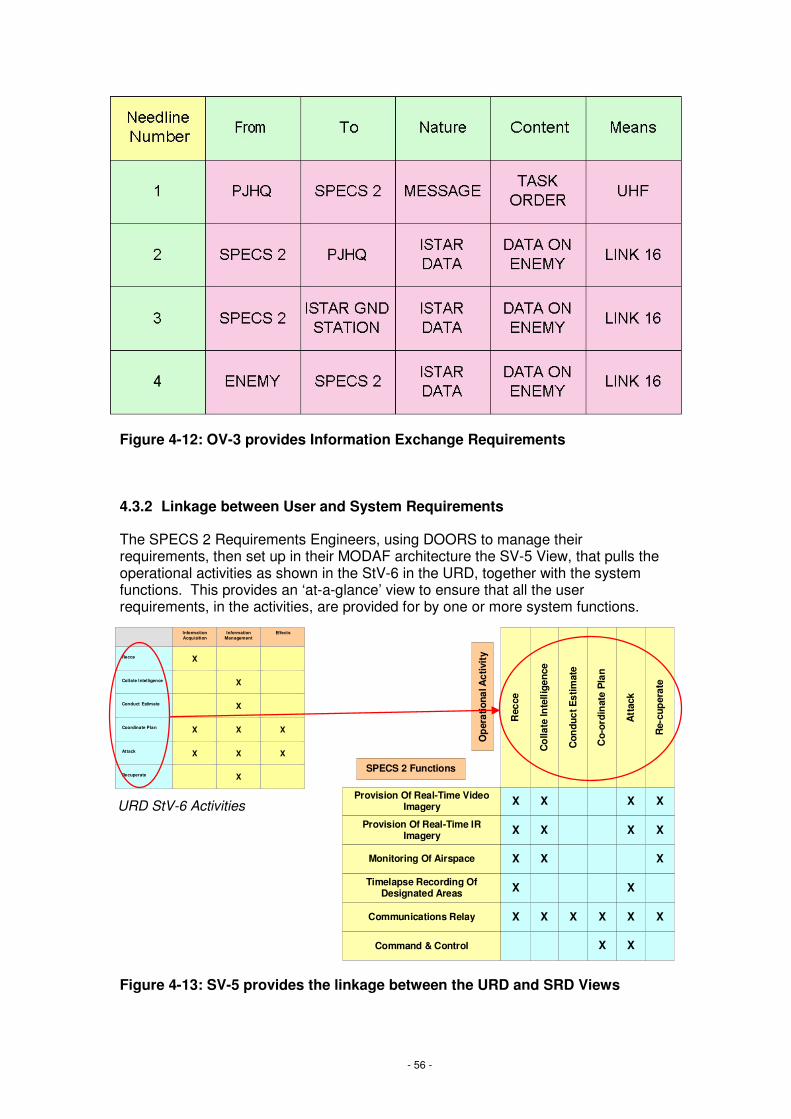
- 56 -
Figure 4-12: OV-3 provides Information Exchange Requirements
4.3.2 Linkage between User and System Requirements
The SPECS 2 Requirements Engineers, using DOORS to manage their requirements, then set up in their MODAF architecture the SV-5 View, that pulls the operational activities as shown in the StV-6 in the URD, together with the system functions. This provides an ‘at-a-glance’ view to ensure that all the user requirements, in the activities, are provided for by one or more system functions.
Figure 4-13: SV-5 provides the linkage between the URD and SRD Views
Provision Of Real-Time VideoImagery
Provision Of Real-Time IRImagery
Monitoring Of Airspace
Timelapse Recording OfDesignated Areas
Communications Relay
Command & Control
Rec
ce
Co
llate
Inte
llige
nce
Con
duct
Est
imat
e
Co-
ordi
nat
e P
lan
Att
ack
Re-
cup
erat
e
X X
X X
X X
X
X X X X
X
X
X
X X
X
X X
X X
Op
erat
iona
l Act
ivit
y
SPECS 2 Functions
Information Acquisition
Information Management
Effects
Recce X
Collate Intelligence X
Conduct Estimate X
Coordinate Plan X X X
Attack X X X
Recuperate X
Information AcquisitionInformation AcquisitionInformation Acquisition
Information ManagementInformation
ManagementInformation
ManagementEffectsEffectsEffects
RecceRecceRecce XXX
Collate IntelligenceCollate IntelligenceCollate Intelligence XXX
Conduct EstimateConduct EstimateConduct Estimate XXX
Coordinate PlanCoordinate PlanCoordinate Plan XXX XXX XXX
AttackAttackAttack XXX XXX XXX
RecuperateRecuperateRecuperate XXX
URD StV-6 Activities
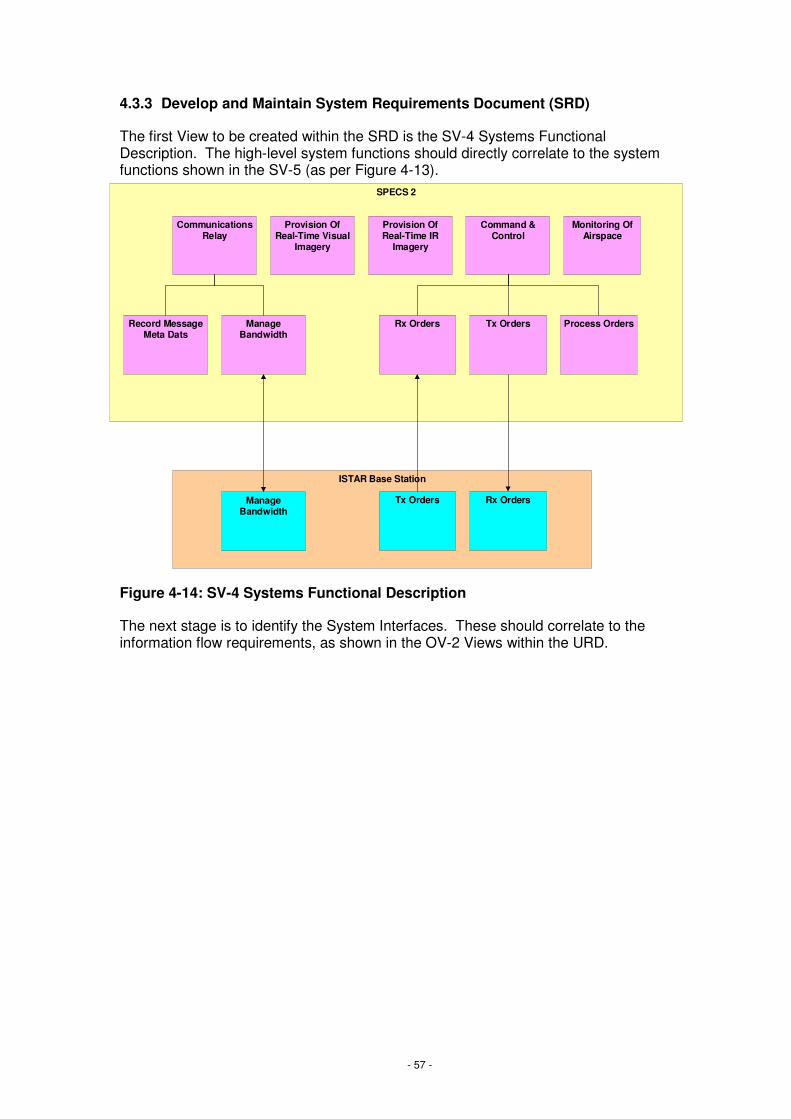
- 57 -
4.3.3 Develop and Maintain System Requirements Document (SRD)
The first View to be created within the SRD is the SV-4 Systems Functional Description. The high-level system functions should directly correlate to the system functions shown in the SV-5 (as per Figure 4-13).
Figure 4-14: SV-4 Systems Functional Description
The next stage is to identify the System Interfaces. These should correlate to the information flow requirements, as shown in the OV-2 Views within the URD.
SPECS 2
ISTAR Base Station
Provision OfReal-Time Visual
Imagery
Provision OfReal-Time IR
Imagery
CommunicationsRelay
Monitoring OfAirspace
Command &Control
ManageBandwidth
Rx Orders Tx Orders Process OrdersRecord MessageMeta Dats
ManageBandwidth
Tx Orders Rx Orders

- 58 -
Figure 4-15: SV-1 showing the system interfaces
Each interface needline relates to an information needline within the OV-2. These System to System connections are drawn together in the SV-3 Systems-Systems Matrix, which completes the System View set for Initial Gate submission:
SPECS 2
Video Recorder
Command &Control
Data Analysis
CommunicationsRelay
ISTAR Base Station
Command &Control
Aircraft Carrier
PJHQ
US JSTAR
CommunicationsRelay
Command &Control
CommunicationsRelay

- 59 -
Figure 4-16: SV-3 Systems-Systems Matrix
Post-Initial Gate, the interface requirements are specified in more detail.
The ports used for each System Interface are defined on an SV-2a System Port Specification View. In this case, there is a need for SPECS 2 to transfer information with the US JSTAR asset. The SPECS 2 team therefore first of all obtain the SV-2a from the US JSTAR team:
X
Systems SA
TC
OM
BO
WM
AN
BD
E H
Q C
OM
MS
PJH
Q C
OM
MS
Air
craf
t C
arri
er
ISTA
R B
ase
Sta
tion
NE
ME
SIS
SP
EC
S 2
KE
STR
EL
US
JSTA
R
SATCOM
BOWMAN
BDE HQ COMMS
PJHQ COMMS
Aircraft Carrier
ISTAR Base Station
NEMESIS
SPECS 2
KESTREL
USJSTAR
X
X
X
X
X
X
X
X
X
X
X
X
X
X
X X X
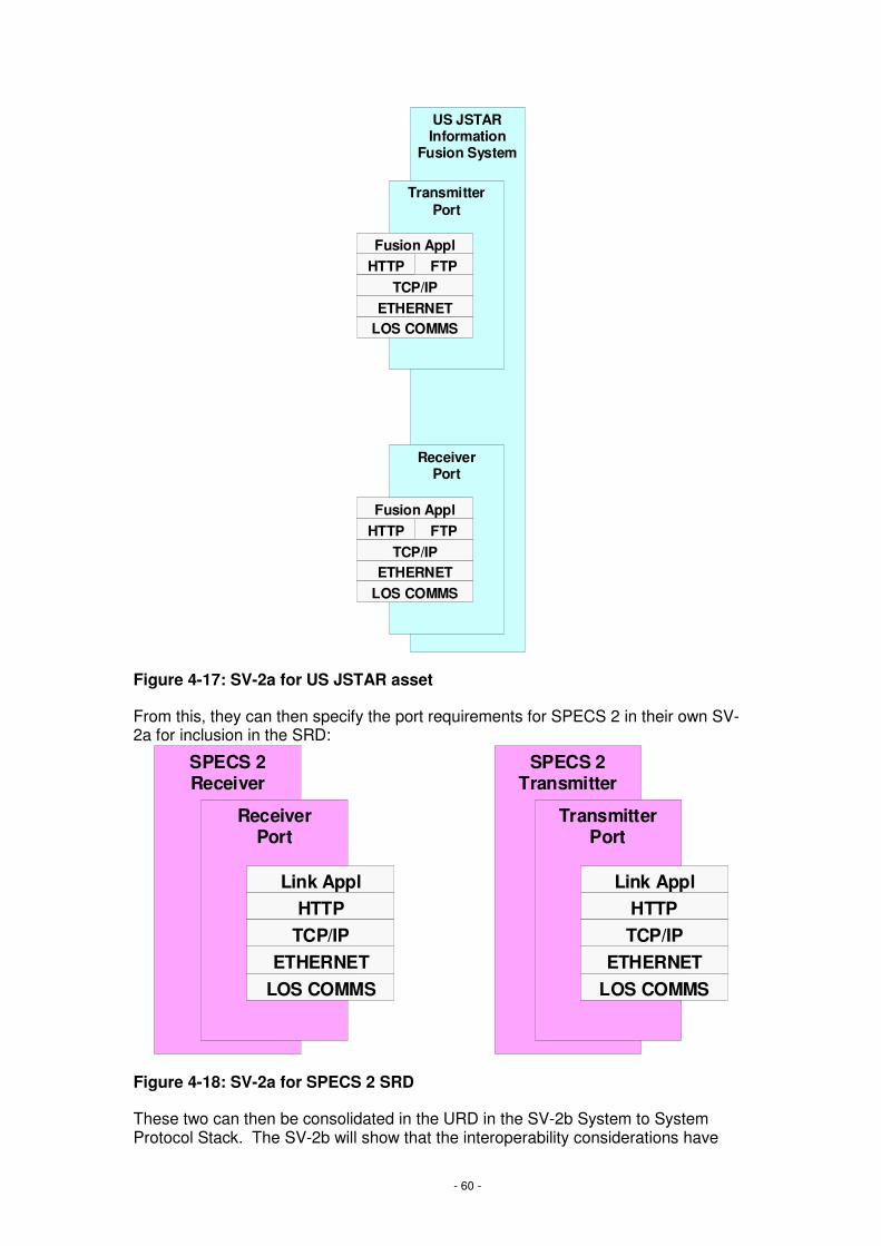
- 60 -
Figure 4-17: SV-2a for US JSTAR asset
From this, they can then specify the port requirements for SPECS 2 in their own SV-2a for inclusion in the SRD:
Figure 4-18: SV-2a for SPECS 2 SRD
These two can then be consolidated in the URD in the SV-2b System to System Protocol Stack. The SV-2b will show that the interoperability considerations have
US JSTARInformation
Fusion System
ReceiverPort
ETHERNETLOS COMMS
HTTPTCP/IP
FTPFusion Appl
TransmitterPort
ETHERNETLOS COMMS
HTTPTCP/IP
FTPFusion Appl
SPECS 2Receiver
SPECS 2Transmitter
ReceiverPort
ETHERNETLOS COMMS
HTTPTCP/IP
TransmitterPort
ETHERNETLOS COMMS
HTTPTCP/IP
Link ApplLink Appl

- 61 -
been taken into account – particularly for the Main Gate submission and assurance by IOCA.
Figure 4-19: SV-2b System-to-System Protocol Stack
The final stage in the interface specification is to link the system interfaces to the organisational information exchange requirements defined in the URD (through the OVs), through the use of SV-2c System Connectivity Clusters. This shows the end-to-end connectivity to satisfy one or more needlines as identified in OV-2a. These diagrams can also be used to model the implementation of kill chains:
SPECS 2Receiver
SPECS 2Transmitter
ReceiverPort
ETHERNETLOS COMMS
HTTPTCP/IP
TransmitterPort
US JSTARInformation
Fusion System
ReceiverPort
TransmitterPort
ETHERNETLOS COMMS
HTTPTCP/IP
SPECS 2 Transmitt
SPECS 2 Receive
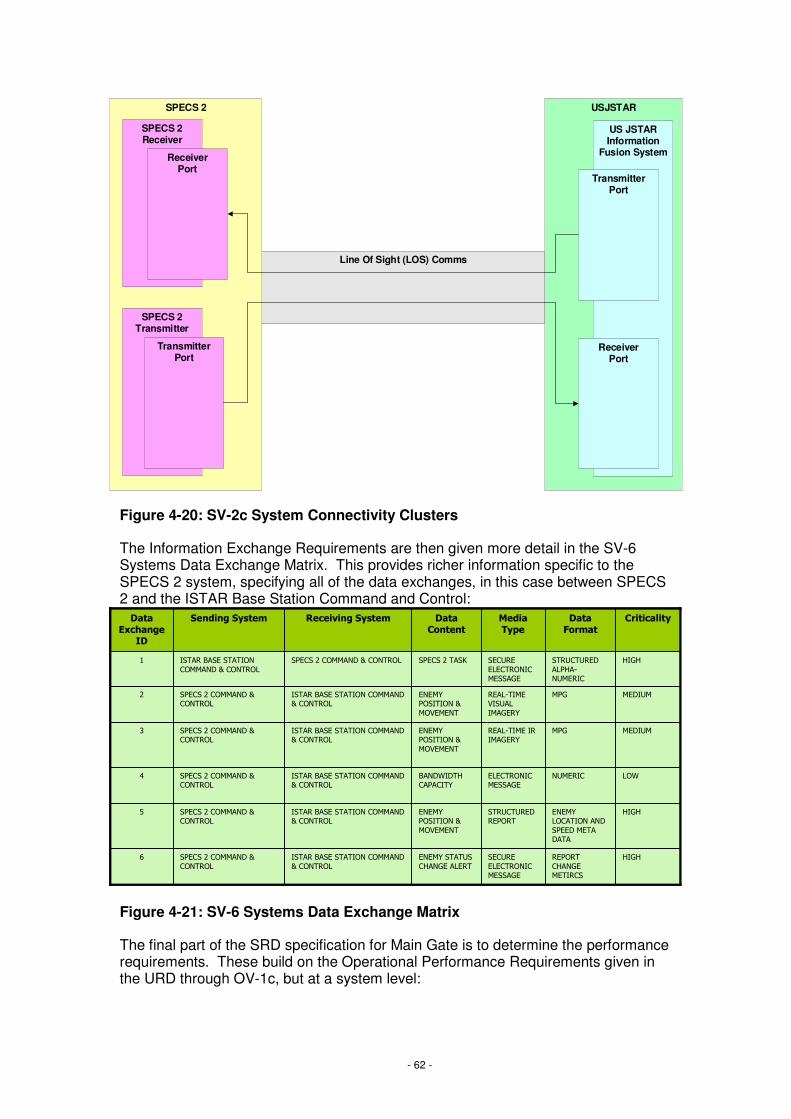
- 62 -
Figure 4-20: SV-2c System Connectivity Clusters
The Information Exchange Requirements are then given more detail in the SV-6 Systems Data Exchange Matrix. This provides richer information specific to the SPECS 2 system, specifying all of the data exchanges, in this case between SPECS 2 and the ISTAR Base Station Command and Control:
Figure 4-21: SV-6 Systems Data Exchange Matrix
The final part of the SRD specification for Main Gate is to determine the performance requirements. These build on the Operational Performance Requirements given in the URD through OV-1c, but at a system level:
Line Of Sight (LOS) Comms
SPECS 2 USJSTAR
SPECS 2Receiver
SPECS 2Transmitter
ReceiverPort
TransmitterPort
US JSTARInformation
Fusion System
ReceiverPort
TransmitterPort
������
�����������������
����������������
�����������������
������������������
���������������
�������
������
�����������������
���������
������
� �����������
����������������
�������������
�������
���
���
����������
��� ���������
����� ����
�� �����������
� ���������
�����!�����������������
"�������
�����#�������"
�������
$
�� �������������"
��������
�����!�����������������"�������
�����#�������"�������
%
��&!���&��� ��������
�����!�����������������"�������
�����#�������"�������
'
�������������������"
��������
�����!�����������������"�������
�����#�������"�������
(
�������������������"
��������
�����!�����������������"�������
�����#�������"�������
#
�� �����#���)�����#�������"������������!����������
�������"�������
�
���������������� �����
��������������������������������������������
������
�����������������
����������������
�����������������
������������������
���������������
�������
������
�����������������
���������
������
� �����������
����������������
�������������
�������
���
���
����������
��� ���������
����� ����
�� �����������
� ���������
�����!�����������������
"�������
�����#�������"
�������
$
�� �������������"
��������
�����!�����������������"�������
�����#�������"�������
%
��&!���&��� ��������
�����!�����������������"�������
�����#�������"�������
'
�������������������"
��������
�����!�����������������"�������
�����#�������"�������
(
�������������������"
��������
�����!�����������������"�������
�����#�������"�������
#
�� �����#���)�����#�������"������������!����������
�������"�������
�
���������������� �����
��������������������������������������������
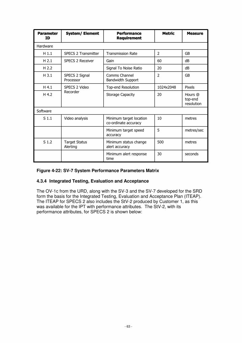
- 63 -
Figure 4-22: SV-7 System Performance Parameters Matrix
4.3.4 Integrated Testing, Evaluation and Acceptance
The OV-1c from the URD, along with the SV-3 and the SV-7 developed for the SRD form the basis for the Integrated Testing, Evaluation and Acceptance Plan (ITEAP). The ITEAP for SPECS 2 also includes the StV-2 produced by Customer 1, as this was available for the IPT with performance attributes. The StV-2, with its performance attributes, for SPECS 2 is shown below:
��*+���
*!#,�����-�����.��� �� #/#
�!#��00.�1����-!��*+�* 1�233��
�����#�����-�����..��
(/�
��4�-.�,#'4#,'5��3���*��.�-2 ��������#��*�������*��
'/�
�2�.6 �3���*��.�-2 ���
#,� �������3��� 7 '/#
��8 +���
0� ��.�,����020 ���� -��� ��������*��� ����2���7
��*�����-7.�.��/�
0� ��..��%����020 ���� .3��*���2���7
.����*.
0� ��.
*!
�!
�������
(,����020�-�� ��.3��.� �0�
%,,����020. � 2.�1�����-�� ���2���7
����� � � 2.�-�� ���
��/#
$,���������#�����9�� #/�
#����.0�..����� ������#����.0� �� �/�
���������� ��������� ��������
������!�������������������

- 64 -
Figure 4-23: StV-2 Capability Functions with Performance Attributes
Performance requirements such as the Range and Duration were included as part of the ITEAP, to confirm that the required Capability has been delivered.
4.4 Systems / Technology
4.4.1 Identify technology and procurement options
The StV-3 Capability Phasing View from Customer 1 for SPECS 2 shows that a new ISTAR Base Station is being introduced during the time that SPECS 2 is in service:
Information Acquisition Information Management Effects
1. StrategicRange: 120km - 1000kmDuration: 24hrs
1. Analysis 1. TargetingAccuracy: 10m
2. OperationalRange: 20km - 120kmDuration: 20hrs
2. Fusion 2. Plan Engagement
3. TacticalRange: 0km - 20kmDuration: 16hrs
3. Quality Assurance 3. Conduct Engagement
4. Dissemination 4. Battle Damage Assessment
Information AcquisitionInformation AcquisitionInformation Acquisition Information ManagementInformation ManagementInformation Management EffectsEffectsEffects
1. StrategicRange: 120km - 1000kmDuration: 24hrs
1. StrategicRange: 120km - 1000kmDuration: 24hrs
1. Analysis1. Analysis 1. TargetingAccuracy: 10m1. TargetingAccuracy: 10m
2. OperationalRange: 20km - 120kmDuration: 20hrs
2. OperationalRange: 20km - 120kmDuration: 20hrs
2. Fusion2. Fusion 2. Plan Engagement2. Plan Engagement
3. TacticalRange: 0km - 20kmDuration: 16hrs
3. TacticalRange: 0km - 20kmDuration: 16hrs
3. Quality Assurance3. Quality Assurance 3. Conduct Engagement3. Conduct Engagement
4. Dissemination4. Dissemination 4. Battle Damage Assessment4. Battle Damage Assessment

- 65 -
Figure 4-24: StV-3 Capability Phasing
Therefore when considering the technology options, interoperability with both NEMESIS ISTAR Base Station and the ISTAR Base Station must be considered.
This is considered along with the SV-9 Technology Forecast, which shows how technology will change during the life of the SPECS 2 system:
Figure 4-25: SV-9 Technology Forecast
Along with the SV-9, the TV-2 shows how standards are likely to evolve. The two taken together provide a long-term view of changes, to which the chosen solution for SPECS 2 will need to adapt.
Capability Functions Epoch 1 Epoch 2 Epoch 3
Information Acquisition
Strategic ISTAR NEMESIS NEMESIS
Operational ISTAR SPECS SPECS 2 SPECS 2
Tactical ISTAR LOOKER KESTREL KESTREL
Information Management
Analysis NEMESIS NEMESISISTAR BASE STATION
ISTAR BASE STATION
Fusion NEMESIS NEMESISISTAR BASE STATION
ISTAR BASE STATION
Quality Assurance NEMESIS NEMESISISTAR BASE STATIN
ISTAR BASE STATION
Dissemination BOWMAN, SAT BOWMAN, SAT
Effects
Targeting LOOKER, SPECS KESTREL, SPECS 2
KESTREL, SPECS 2
Plan Engagement BISA BISA
Conduct Engagement CR2, MILAN, FGA CR2, FGA CR2, FGA
BDA FGA, SAT FGA, SAT FGA, SAT
Capability FunctionsCapability FunctionsCapability Functions Epoch 1Epoch 1Epoch 1 Epoch 2Epoch 2Epoch 2 Epoch 3Epoch 3Epoch 3
Information AcquisitionInformation Acquisition
Strategic ISTARStrategic ISTAR NEMESISNEMESISNEMESIS NEMESISNEMESISNEMESIS
Operational ISTAROperational ISTAR SPECSSPECSSPECS SPECS 2SPECS 2SPECS 2 SPECS 2SPECS 2SPECS 2
Tactical ISTARTactical ISTAR LOOKERLOOKERLOOKER KESTRELKESTRELKESTREL KESTRELKESTRELKESTREL
Information ManagementInformation Management
AnalysisAnalysis NEMESISNEMESISNEMESIS NEMESISISTAR BASE STATION
NEMESISISTAR BASE STATION
NEMESISISTAR BASE STATION
ISTAR BASE STATIONISTAR BASE STATIONISTAR BASE STATION
FusionFusion NEMESISNEMESISNEMESIS NEMESISISTAR BASE STATION
NEMESISISTAR BASE STATION
NEMESISISTAR BASE STATION
ISTAR BASE STATIONISTAR BASE STATIONISTAR BASE STATION
Quality AssuranceQuality Assurance NEMESISNEMESISNEMESIS NEMESISISTAR BASE STATIN
NEMESISISTAR BASE STATIN
NEMESISISTAR BASE STATIN
ISTAR BASE STATIONISTAR BASE STATIONISTAR BASE STATION
DisseminationDissemination BOWMAN, SATBOWMAN, SATBOWMAN, SAT BOWMAN, SATBOWMAN, SATBOWMAN, SAT
EffectsEffects
TargetingTargeting LOOKER, SPECSLOOKER, SPECSLOOKER, SPECS KESTREL, SPECS 2
KESTREL, SPECS 2
KESTREL, SPECS 2
KESTREL, SPECS 2
KESTREL, SPECS 2
KESTREL, SPECS 2
Plan EngagementPlan Engagement BISABISABISA BISABISABISA
Conduct EngagementConduct Engagement CR2, MILAN, FGACR2, MILAN, FGACR2, MILAN, FGA CR2, FGACR2, FGACR2, FGA CR2, FGACR2, FGACR2, FGA
BDABDA FGA, SATFGA, SATFGA, SAT FGA, SATFGA, SATFGA, SAT FGA, SATFGA, SATFGA, SAT
SPECS 2 must interoperate with both the NEMESIS ISTAR Base Station in Epoch 2, and the ISTAR Base Station in Epoch 3
Service Orientated Networking
Virtual Networks (including VLAN)
Fixed Point To Point Networks
Networking philosophy
XP
Medium Term3-6 years
Not disclosedXPWindows Version
180GB60GBDefault storage capacity for Personal Computer
10Ghz Processor2Ghz ProcessorDefault digital signal processor speeds
Long Term6-9 years
Short Term1-3 years
Area

- 66 -
Figure 4-26: TV-2 Technical Standards Forecast
4.4.2 Demonstrate ability to deliver integrated capability
The Systems and Technology workstream will draw on the Views created within the URD and SRD to demonstrate integration.
The OV-2 (in Figure 4-11) and SV-6 (in Figure 4-21) show how the system meets interoperability requirements, communicating with the ISTAR Base Station and the Data Exchanges that specify this data link.
The OV-3 (in Figure 4-12) and SV-1 (in Figure 3-11) show the Information Exchange Requirements, and how connections will be inserted between systems to meet these.
The OV-1c (in Figure 4-8) and the SV-7 (in Figure 4-22) show the required operational and system performance factors that are being taken into account when specifying the system.
4.4.3 Technology Insertion
The forecast information within the SV-9Technology Forecast and TV-2 Technical Standards Forecast is maintained, so that it will highlight any likely issues in the future. These would then be raised with Customer 1, for them to initiate any required upgrades or improvements.
4.5 Industry / Suppliers
4.5.1 Involve Industry
The SPECS 2 IPT decide to involve industry from the outset, in order that they can best exploit the technologies available. They take the OV-1a (as per Figure 4-7) and OV-1c (as per Figure 4-8) for initial industry consultation, along with the OV-2 (in Figure 4-11).
During the consultation with industry, the IPT is informed that there is a significant cost increase to specify that the flight time needs to be 24hrs, prior to 2027. This would require a jump to unproven technology, however the industry partners believed that this would be proven by 2027. On referring back to Customer 1, it is agreed that a flight time of 20hrs will provide the required level of capability until such time as the
WAN: SDH TechnologyLAN: Gigabit Ethernet Backbone
XMIv2.1
Medium Term3-6 years
WAN: PDH TechnologyMOD Communications/ Networking Policy
MOD System Of Systems Engineering Management Plan (SEMP)
Local Systems Engineering Management Plan (SEMP)
MOD Systems Engineering Standards
MODAF v2.0MODAF v1.0XMI v2.0
MODAF
Long Term6-9 years
Short Term1-3 years
Standard/ Policy

- 67 -
new technology is proven, and so the requirement is lowered to 20hrs to achieve the significant cost reduction this affords.
Similarly, with regards to the number of video channels required, industry inform that it is currently possible to obtain 4 video channels using the same technology as would be used to provide 2 channels, therefore this requirement is increased to take advantage of the technology available.
Figure 4-27: Modified OV-1c after industry consultation
4.5.2 System Synthesis
The SRD Views described in Section 4.3.3 form the basis for prototyping with industry, along with considerations from the SV-9 and TV-2 forecasts, shown in Figure 4-25 and Figure 4-26 respectively.
4.5.3 Negotiate Contract
The SPECS 2 contract negotiations are held, using the architectural model developed through the URD validation and the SRD development. The technical findings from the initial industry consultation also give the negotiators a good grounding in the technical possibilities to drive out the risk from the contract.
4.5.4 Deliver the solution
The chosen supplier agrees in the contract negotiations to provide high-level MODAF Views as part of their solution delivery. These Views are fed back to the IPT, who consolidate them for inclusion into MODAR.
4.5.5 Carry out any agreed upgrades or improvements
Upgrades and improvements are undertaken as Customer 2 identifies them, and as agreed in the contract, shown in the TLMP (see next section). The increases in available technology are also included in the upgrade plan: for example the increase in flight duration to 24hrs in 2027, highlighted during initial industry involvement.
15510152530Maximum time delay (seconds) viewing tasked location
SPECS 2 Video Delay
55567810Number of days required for maintenance
SPECS 2 Downtime
6444422Number of individual video channels provided
SPECS 2 Video Support
300
24
2027
300
36
2028
500
36
2029
600
36
2030
SPECS 2 Range
SPECS 2 Flight Time
Attribute
300
24
2026
1200300Maximum number of km from ISTAR base station
4824Maximum number of hours for a single flight
Target2025Measure
15510152530Maximum time delay (seconds) viewing tasked location
SPECS 2 Video Delay
55567810Number of days required for maintenance
SPECS 2 Downtime
6444444Number of individual video channels provided
SPECS 2 Video Support
300
24
2027
300
36
2028
500
36
2029
600
36
2030
SPECS 2 Range
SPECS 2 Flight Time
Attribute
300
20
2026
1200300Maximum number of km from ISTAR base station
4820Maximum number of hours for a single flight
Target2025Measure

- 68 -
4.6 Through-Life Management
4.6.1 TLMP
The SPECS 2 IPT initiates the Through-Life Management Plan (TLMP) in the Concept Stage. The first TLMP View to be developed is the SV-9 Technology Forecast, which is developed in conjunction with the Systems and Technology workstream. The SV-9 is shown in Figure 4-25.
For the Initial Gate review, the SV-8 Systems Evolution Description is developed within the SPECS 2 architecture. This shows the planned upgrade and improvement path for SPECS 2, and its in-service life span:
Figure 4-28: SV-8 Systems Evolution Description
This provides the development and maintenance costs for inclusion within the Whole-Life Costing for the TLMP.
The TLMP also contains the detailed planning for each Stage. This is taken from the AcV-2, managed within the Project Management workstream (in conjunction with the Through-Life Management team), and an example is shown in Figure 4-3.
4.6.2 Integrated Logistic Support
The ILS team use the architecture to help articulate their requirements. They pull together ILS requirements within an OV-1c, to show the availability, maintainability and reliability requirements for the system:
Figure 4-29: OV-1c articulating ILS requirements
4.7 UML Example
The example in this section is a notional ISTAR example, and is not related to any actual ISTAR work. It is included to provide an alternative to the example Views provided elsewhere in this document, showing the use of UML for View representation.
Release 1
SPECS 2
Release 2 Release 3 Release 4 DisposalPlanning
Q1 2025 Q2 2026 Q4 2028 Q4 2030 Q4 2040
InitialRelease Release +
UrgentAdditionalRequirementsIdentified AtAcceptance
Release + DesirableAdditional RequirementsIdentified At Acceptance Release + Required
Situational Updates Planning for disposal/exension of designed life
7
45
20
2027
6
40
18
2028
5
35
15
2029
5
34
14
2030
SPECS 2 Reliability
SPECS 2 Maintainability
SPECS 2 Availability
Attribute
8
50
30
2026
510Number of days unplanned downtime
3050Support personnel required to maintain SPECS 2
1045Number of days down time
Target2025Measure
7
45
20
2027
6
40
18
2028
5
35
15
2029
5
34
14
2030
SPECS 2 Reliability
SPECS 2 Maintainability
SPECS 2 Availability
Attribute
8
50
30
2026
510Number of days unplanned downtime
3050Support personnel required to maintain SPECS 2
1045Number of days down time
Target2025Measure
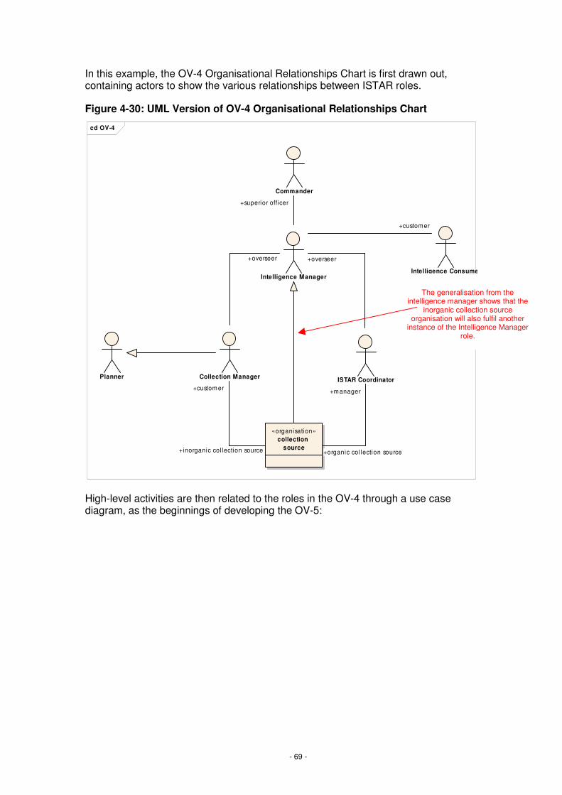
- 69 -
In this example, the OV-4 Organisational Relationships Chart is first drawn out, containing actors to show the various relationships between ISTAR roles.
Figure 4-30: UML Version of OV-4 Organisational Relationships Chart
High-level activities are then related to the roles in the OV-4 through a use case diagram, as the beginnings of developing the OV-5:
cd OV-4
Collection Manager ISTAR Coordinator
Intelligence Manager
Commander
Intelligence Consumer
Planner
«organisation»collection
source
+superior officer
+manager
+organic col lection source
+customer
+inorganic col lection source
+customer
+overseer+overseer
The generalisation from the intelligence manager shows that the
inorganic collection source organisation will also fulfil another
instance of the Intelligence Manager role.
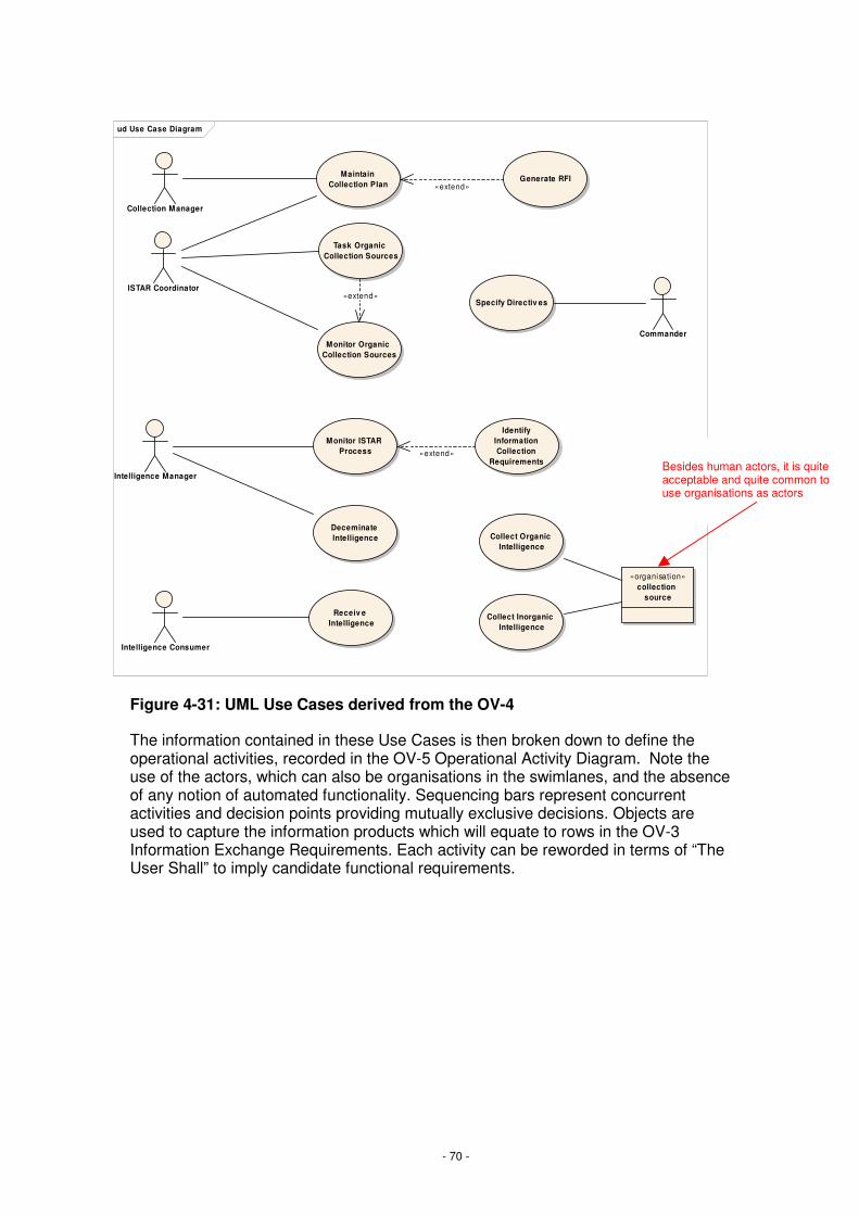
- 70 -
Figure 4-31: UML Use Cases derived from the OV-4
The information contained in these Use Cases is then broken down to define the operational activities, recorded in the OV-5 Operational Activity Diagram. Note the use of the actors, which can also be organisations in the swimlanes, and the absence of any notion of automated functionality. Sequencing bars represent concurrent activities and decision points providing mutually exclusive decisions. Objects are used to capture the information products which will equate to rows in the OV-3 Information Exchange Requirements. Each activity can be reworded in terms of “The User Shall” to imply candidate functional requirements.
ud Use Case Diagram
Collection Manager
Maintain Collection Plan
Generate RFI
Task Organic Collection Sources
Monitor Organic Collection Sources
ISTAR Coordinator
Intelligence Manager
Monitor ISTAR Process
Identify Information Collection
Requirements
Deceminate Intelligence
Commander
Specify Directiv es
Intelligence Consumer
Receiv e Intelligence
Collect Organic Intelligence
Collect Inorganic Intelligence
«organisation»collection
source
«extend»
«extend»
«extend»
Besides human actors, it is quite acceptable and quite common to use organisations as actors

- 71 -
ad Activ ity Diagram
ISTA
R C
oord
inat
orC
olle
ctio
n M
anag
er
Identify Information Collection
Requirements
:Intelligence Collection Plan
Determine how information can
be collected
Identify required
collection capability
Allocate capability
to task
:Battlespace Management
Information Source
Identify w hat information should
be collected
Identify w hen information needs to be
collected
Raise RFI
:Intelligence Estimate
:IPB
Monitor Task
Update plan
RFI
Update Plan
Monitor Response
Notify Intelligence
Manager
:Intelligence Collection Plan
Notify Intelligence Manager and Collection
Manager
[inorganic]
[organic]
[else]
[does not meetrequirement]
[else]
[does not meetrequirement]
Figure 4-32: UML representation of an OV-5 Operational Activity Model
An SV-4 Systems Functional Description would then be developed as the system moved into the SRD development phase. A hybrid SV-4 is shown below, depicting how part of the OV-5 could be implemented in a notional ISTAR system that allow collaborative working between the Collection Manager and the ISSTAR Coordinator. This is a hybrid View, as it contains information pertaining to interfacing systems, which is not required in a standard SV-4.
Most of the activity takes place in the system of interest with assumptions placed against interfacing systems. Any transitions that cross a swim lane indicate a potential interface or HCI. Care should be taken with these diagrams to only show the logical activities required and not to drive down into design. Use notes to show where there may be alternative solutions.

- 72 -
ad SV4
Situ
atio
n A
war
enes
s S
yste
mIS
TAR
Sys
tem
ISTA
R C
oord
inat
orC
olle
ctio
n M
ana
ger
Display Collection
Requirements
Input collection
Tasks
Update Task List
Display Task List
Prov ide Geographical
information
Display Geographical
Locations
battlespace topography
Select Geographical
Location corrisponding
to task
Display av ailable
assetsRequest Geographical
Information
Prov ide av ailable
asstes
Request assets for
geographical location
asset list[fi l tered]
Display task list M ap
Assets to Tasks
Allocate Assets to
Tasks
Update collection
plan
Update asset status
Design Consideration:T hese two exchanges could be achi ved wi thin a single exchange.
Figure 4-33: UML representation of a hybrid SV-4 Systems Functionality Description

- 73 -
5. Document Maintenance
It is intended that the MODAF product suite will evolve through time in order to reflect learning from experience, changes to the MOD’s processes and the evolution of architectural best practice. A change control process will be established for all MODAF products and suggestions upon the refinement / improvement of this and related products is welcome. The formal MODAF change control process shall be published in due course. In the interim, suggestions should be forwarded to the MODAF point of contact, EC CCII Cap Strat, located in Main Building.
Acknowledgements
This document has been developed by MODAF partners as part of the MODAF 1.0 Baseline that is being prepared by DEC CCII supported by the IA. Other organisations that have contributed to the content and / or review of this document are:
• DII IPT
• FRES IPT
• CSIS IPT
• DCBA IPT
• Satcom IPT
• Sea Technology Group (DPA)
• DCSA
• PDG Standardisation
The role of Industry is also acknowledged in providing support to the MODAF development and in reviewing the MODAF products prior to its release. The authors acknowledge Hi-Q Systems for providing the UML Views used in the Worked Example section of this document.
MODAF partners
The MODAF 1.0 Baseline has been developed for the MOD by MODAF partners. The MODAF partners team leaders for this work have been:
Fariba Hozhabrafkan
Cornwell Management Consultants Home Barn Court The Street Effingham Surrey
KT24 5LG
Tel: 01372 456086
Dave Mawby
PA Consulting Group 123 Buckingham Palace Road London SW1W 9SR
Tel: 020 7730 9000

- 74 -
Appendix A: Large-Scale Diagrams
This section provides large-scale versions of the diagrams included in this document, for ease of reading.
A.1 Process Diagrams
The following pages contain the process diagrams as shown at the start of each sub-section within section 3, to a larger scale than was possible within the text.

- 75 -
Figure 3-3: Key MODAF Relationship to Project Management Activities
CONCEPT ASSESSMENT DEMONSTRATION MANUFACTURE IN-SERVICE DISPOSAL
Form the IPT
URD
View Set
Essential View producedoutside this workstreamTV-1
InitialGate
Essential View producedby this workstream
Highly Desirable View producedby this workstream
Highly Desirable View producedoutside this workstream
TLMPAcV-2URD
SV-1OV-2
Managedependency
risks
OV-5StV-5
SRDURD
MainGate
SRD ITEAPTLMP
Placecontract(s) tomeet the SRD
SRD
URD
Wind down ofIPT
Key
TV-1
SV-1 TV-1OV-2
AcV-2

- 76 -
Figure 3-6: MODAF relationship to Requirements Management
CONCEPT ASSESSMENT DEMONSTRATION MANUFACTURE IN-SERVICE DISPOSAL
View Set
Essential View producedoutside this workstream
Essential View producedby this workstream
Highly Desirable View producedby this workstream
Highly Desirable View producedoutside this workstream
Key
User Requirements Document (URD)
StV-6
OV-1
OV-2
OV-2
OV-3
OV-5
TV-1
OV-3
OV-5
TV-1
Linkage between user andsystem requirements SV-5
SV-4
OV-5
System Requirements Document (SRD)URD
SV-1
SV-2
SV-3
SV-4
SV-6
SV-7
TV-1
NB: The TV-1 contained inthe SRD will be at a lowerlevel than that in the URD.This more detailed TV-1 iscreated by the IPT, basedon the high-level TV-1 in
the URD.
SV-2
SV-6
SV-7
TV-1
Integrated Testing, Evaluation and AcceptancePlan
StV-2
OV-1c
SV-7
SV-3
SRD
OV-7 OV-7

- 77 -
Figure 3-17: MODAF Relationship to System / Technology workstream
CONCEPT ASSESSMENT DEMONSTRATION MANUFACTURE IN-SERVICE DISPOSAL
View Set
Essential View producedoutside this workstream
Essential View producedby this workstream
Highly Desirable View producedby this workstream
Highly Desirable View producedoutside this workstream
Key
Identify technology and procurement options
StV-3
TV-1
SV-9
TV-2
SV-9
TV-2
updated
updated
Demonstrate ability to deliverintegrated capability
OV-2
OV-3
SV-1
SV-7
SV-6
OV-1c
SV-7
Technology insertion
SV-9
TV-2

- 78 -
Figure 3-19: MODAF Relationship to Industry workstream
CONCEPT ASSESSMENT DEMONSTRATION MANUFACTURE IN-SERVICE DISPOSAL
View Set
Essential View producedoutside this workstream
Essential View producedby this workstream
Highly Desirable View producedby this workstream
Highly Desirable View producedoutside this workstream
Key
Involve Industry
OV-1
OV-2
System SynthesisSV-9
TV-2
SRD
Negotiate Contract
URD
SRD
Deliver Solution
Carry out any agreedupgrades or improvements
StV-2
StV-3
SV-8

- 79 -
Figure 3-23: MODAF Relationship to Through-Life Management
CONCEPT ASSESSMENT DEMONSTRATION MANUFACTURE IN-SERVICE DISPOSAL
View Set
Essential View producedoutside this workstream
Essential View producedby this workstream
Highly Desirable View producedby this workstream
Highly Desirable View producedoutside this workstream
Key
Through-Life Management Plan
SV-9
SV-8
AcV-2
SV-8
TV-2
TV-1
Integrated Logistic Support
OV-1c
NB: An OV-1c for the entire system will be produced byCustomer 1 within the URD. The Through-Life Management
workstream creates an instance of OV-1c pertaining tosustainability, maintainability etc of the system
OV-5

- 80 -
A.2 View Examples
The following pages contain all of the Views used to illustrate the text, in a larger size so that they can be easily read. However, it is important to note that these Views are examples only, containing dummy data. They are intended to show the type of information available in each View.
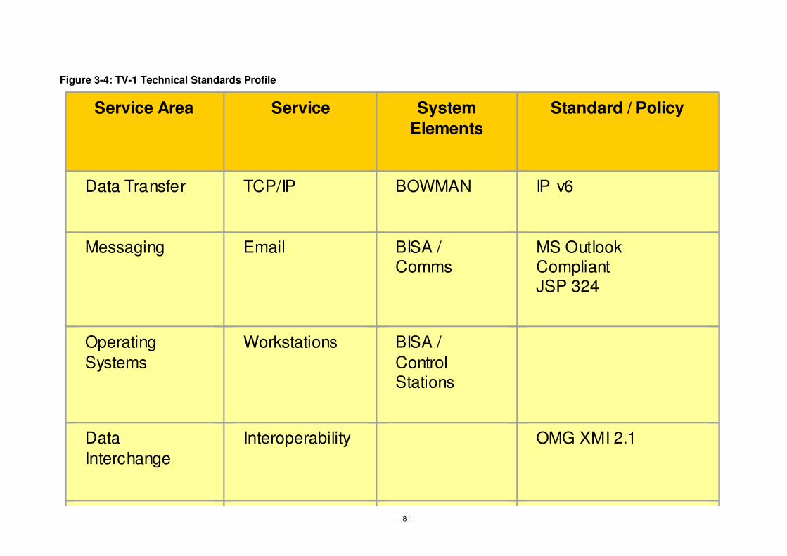
- 81 -
Figure 3-4: TV-1 Technical Standards Profile
Service Area Service System Elements
Standard / Policy
Data Transfer TCP/IP BOWMAN IP v6
Messaging Email BISA / Comms
MS Outlook CompliantJSP 324
Operating Systems
Workstations BISA / Control Stations
Data Interchange
Interoperability OMG XMI 2.1
Service Area Service System Elements
Standard / Policy
Data Transfer TCP/IP BOWMAN IP v6
Messaging Email BISA / Comms
MS Outlook CompliantJSP 324
Operating Systems
Workstations BISA / Control Stations
Data Interchange
Interoperability OMG XMI 2.1
Service AreaService AreaService Area ServiceServiceService System ElementsSystem
ElementsSystem
ElementsStandard / PolicyStandard / PolicyStandard / Policy
Data TransferData TransferData Transfer TCP/IPTCP/IPTCP/IP BOWMANBOWMANBOWMAN IP v6IP v6IP v6
MessagingMessagingMessaging EmailEmailEmail BISA / CommsBISA / CommsBISA / Comms
MS Outlook CompliantJSP 324
MS Outlook CompliantJSP 324
MS Outlook CompliantJSP 324
Operating SystemsOperating SystemsOperating Systems
WorkstationsWorkstationsWorkstations BISA / Control Stations
BISA / Control Stations
BISA / Control Stations
Data InterchangeData InterchangeData Interchange
InteroperabilityInteroperabilityInteroperability OMG XMI 2.1OMG XMI 2.1OMG XMI 2.1

- 82 -
Figure 3-5: AcV-2 SoS Acquisition Programmes

- 83 -
Figure 3-8: SV-5 links the URD and SRD

- 84 -
Figure 3-10: SV-4 Systems Functionality Description

- 85 -
Figure 3-11: SV-1 Systems Interface Description
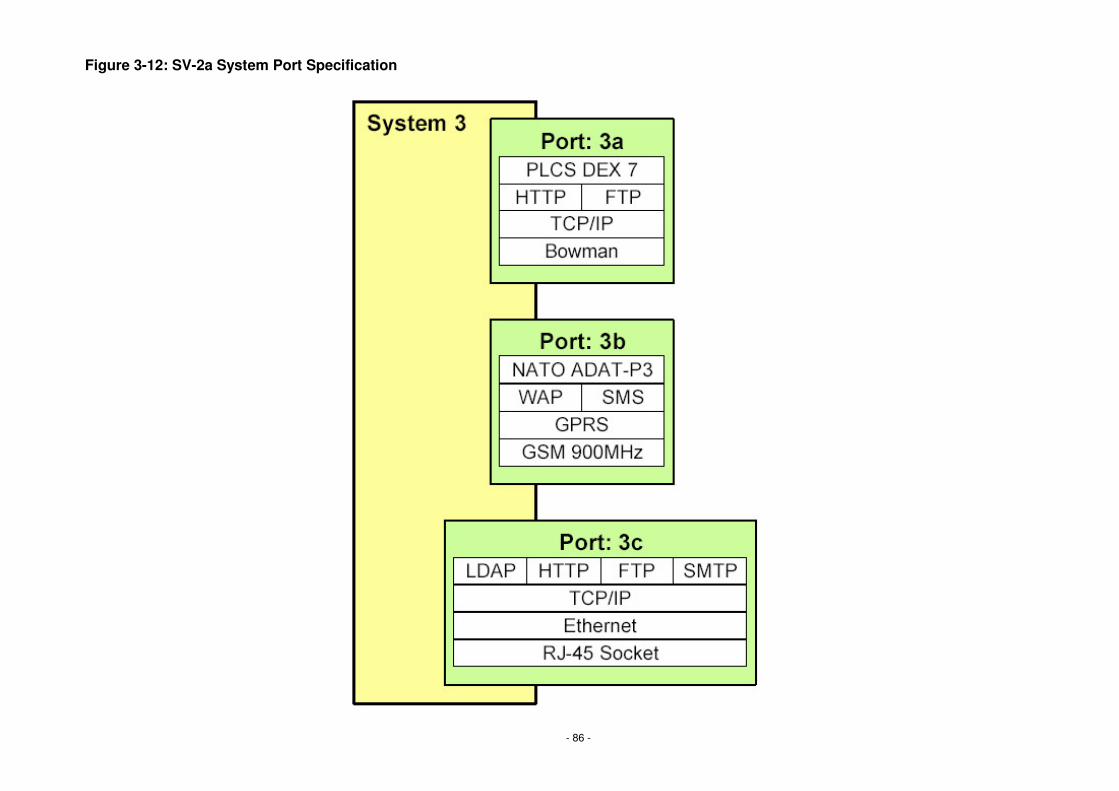
- 86 -
Figure 3-12: SV-2a System Port Specification

- 87 -
Figure 3-13: SV-2b System-to-System Protocol Stack
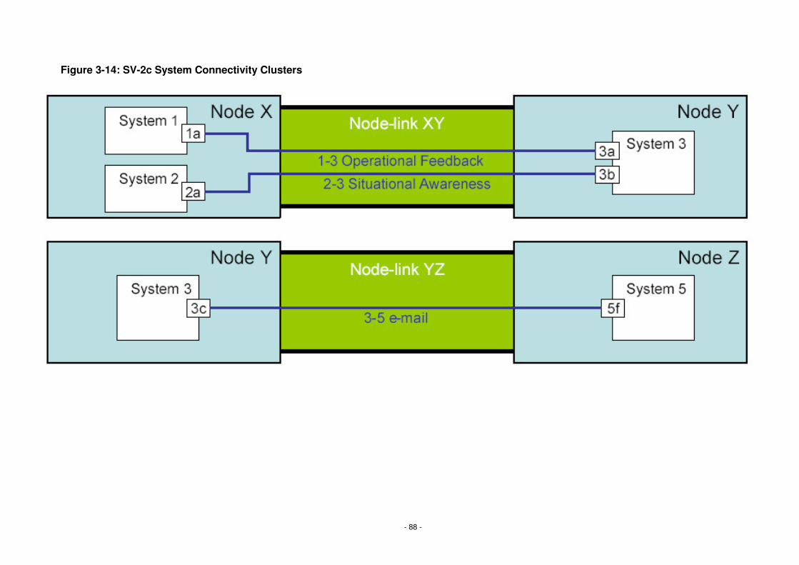
- 88 -
Figure 3-14: SV-2c System Connectivity Clusters

- 89 -
Figure 3-15: SV-3 System-to-System Matrix

- 90 -
Figure 3-16: SV-6 Systems Data Exchange Matrix

- 91 -
Figure 3-18: SV-9 Systems Technology Forecast

- 92 -
Figure 3-20: OV-1a High Level Operational Graphic

- 93 -
Figure 3-21: OV-1b High Level Operational Description
The Assess Battle Damage process starts when the target has been engaged. An initial assessment is made using nearby FRES Scout. This information is passed up to FRES IFS. FRES IFS will order further BDA if necessary (for example if the first assessment was inconclusive). If necessary a further application of effect may be ordered through FRES PM, followed by a further BDA. Once the battle damage assessment has been completed the FRES roles continue with their original tasks.

- 94 -
Figure 3-22: OV-1c Operational Performance Attributes
Attribute Measure Value As - Is Epoch 1 Epoch 2 Target Operational Tempo
Rate of Advance for an Armoured Brigade against light resistance
20 km/day 40 km/day 60 km/day 80 km/day
Synchronisation of Effects
Simultaneous rounds on impact delivered by an Arty Bty
30 rounds 40 rounds 60 rounds 100 rounds
Sortie Rate Period to re-fuel and re-arm an aircraft
4 hours 3 hours 2 hours 1 hours

- 95 -
Figure 3-25: SV-8 Systems Evolution Description
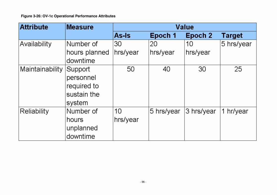
- 96 -
Figure 3-26: OV-1c Operational Performance Attributes

- 97 -
A.3 Worked Example Diagrams
The diagrams on the next few pages are those included in the Worked Example in Section 4.
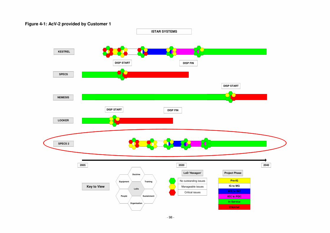
- 98 -
Figure 4-1: AcV-2 provided by Customer 1
ISTAR SYSTEMS
SPECS
DISP START
LOOKER
DISP START DISP FIN
NEMESIS
DISP START
People
Organisation
Sustainment
Equipment Training
Doctrine
LoDs
Pre-IG
IG to MG
MG to IOC
IOC to FOC
In Service
Disposal
Key to View
Project Phase
No outstanding issues
Manageable issues
Critical issues
LoD 'Hexagon'
2005 2020 2040
DISP FIN
SPECS 2
KESTREL

- 99 -
Figure 4-2: Initial TV-1 setting the standards and constraints for the IPT
MOD Sustainment guidelinesSPECS 2 and DLoD support
Ability to sustain capability
Sustainment & Logistics
US Guidance NotesSPECS 2 external US communication network interfaces
Communications/Networking
US Interoperability
MOD Systems Engineering Management Plan (SEMP)
SPECS 2 & interfacesSystems Engineering
MOD Strategy
ISTAR Acceptance ProcedureAll fielded capabilityAcceptance
SOPsAll fielded capabilityOperationsISTAR Governance
Standard/ PolicyApplicable ElementsServiceService Area

- 100 -
Figure 4-3: AcV-2 showing dependency with delivery of KESTREL
ISTAR SYSTEMS
SPECS
DISP START
LOOKER
DISP START DISP FIN
NEMESIS
DISP START
People
Organisation
Sustainment
Equipment Training
Doctrine
LoDs
Pre-IG
IG to MG
MG to IOC
IOC to FOC
In Service
Disposal
Key to View
Project Phase
No outstanding issues
Manageable issues
Critical issues
LoD 'Hexagon'
2005 2020 2040
DISP FIN
SPECS 2
KESTREL
SPECS 2 must be delivered along with KESTREL to fill the Capability Gap left by the disposal of SPECS and LOOKER
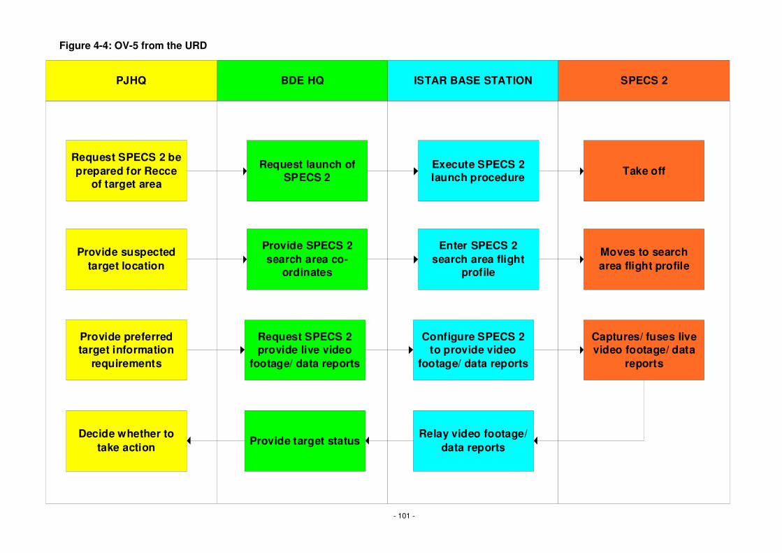
- 101 -
Figure 4-4: OV-5 from the URD
Request SPECS 2 beprepared for Recce
of target area
Request launch ofSPECS 2
PJHQ BDE HQ ISTAR BASE STATION SPECS 2
Execute SPECS 2launch procedure
Provide suspectedtarget location
Provide SPECS 2search area co-
ordinates
Configure SPECS 2to provide video
footage/ data reports
Provide preferredtarget information
requirements
Request SPECS 2provide live video
footage/ data reports
Enter SPECS 2search area flight
profile
Moves to searcharea flight profile
Take off
Captures/ fuses livevideo footage/ data
reports
Relay video footage/data reportsProvide target status
Decide whether totake action

- 102 -
Figure 4-5: StV-5 showing the Capability gap to be addressed
Strategic - PJHQ
Operational -JFHQ
Tactical -Brigade
Tactical - SpecialForces
InformationAcquistion
InformationManagement Effects
BISA
NEMESISSPECS
MILAN
CR2
FGA
EPOCH 1
LOOKER
Strategic - PJHQ
Operational -JFHQ
Tactical -Brigade
Tactical - SpecialForces
InformationAcquistion
InformationManagement Effects
BISA
NEMESIS
CR2
FGA
EPOCH 2
Strategic - PJHQ
Operational -JFHQ
Tactical -Brigade
Tactical - SpecialForces
InformationAcquistion
InformationManagement Effects
BISA
CR2
FGA
EPOCH 3
Any requests to fulfil requirements outside of the Information Acquisition Capability are changes to scope

- 103 -
Figure 4-6: StV-6 within the URD shows the Operational Vignette
Information Acquisition
Information Management
Effects
Recce X
Collate Intelligence X
Conduct Estimate X
Coordinate Plan X X X
Attack X X X
Recuperate X
Information AcquisitionInformation AcquisitionInformation Acquisition
Information ManagementInformation
ManagementInformation
ManagementEffectsEffectsEffects
RecceRecceRecce XXX
Collate IntelligenceCollate IntelligenceCollate Intelligence XXX
Conduct EstimateConduct EstimateConduct Estimate XXX
Coordinate PlanCoordinate PlanCoordinate Plan XXX XXX XXX
AttackAttackAttack XXX XXX XXX
RecuperateRecuperateRecuperate XXX
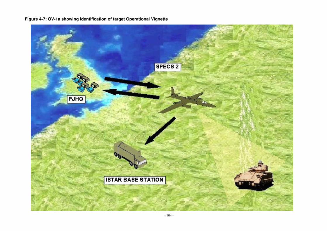
- 104 -
Figure 4-7: OV-1a showing identification of target Operational Vignette

- 105 -
Figure 4-8: OV-1c showing Performance Requirements
15510152530Maximum time delay (seconds) viewing tasked location
SPECS 2 Video Delay
55567810Number of days required for maintenance
SPECS 2 Downtime
6444422Number of individual video channels provided
SPECS 2 Video Support
300
24
2027
300
36
2028
500
36
2029
600
36
2030
SPECS 2 Range
SPECS 2 Flight Time
Attribute
300
24
2026
1200300Maximum number of km from ISTAR base station
4824Maximum number of hours for a single flight
Target2025Measure
15510152530Maximum time delay (seconds) viewing tasked location
SPECS 2 Video Delay
55567810Number of days required for maintenance
SPECS 2 Downtime
6444422Number of individual video channels provided
SPECS 2 Video Support
300
24
2027
300
36
2028
500
36
2029
600
36
2030
SPECS 2 Range
SPECS 2 Flight Time
Attribute
300
24
2026
1200300Maximum number of km from ISTAR base station
4824Maximum number of hours for a single flight
Target2025Measure

- 106 -
Figure 4-10: OV-5 derived from Use Case document
Request SPECS 2 beprepared for Recce
of target area
PJHQ ISTAR BASE STATION SPECS 2
Execute SPECS 2launch procedure
Configure SPECS 2to identify target
Enter SPECS 2search area flight
profile
Moves to searcharea flight profile
Take off
Captures targetvideo and data
Relay video footage/data reports
Analyse video anddata
Provide SPECS 2search area co-
ordinates
Request SPECS 2identify tagret
Decide whether totake action
Store video and data
1
2 3 4
5 6 7
89
10

- 107 -
Figure 4-11: OV-2 showing information flows
PJHQ SPECS 2
ENEMY
ISTAR BASESTATION
ISTAR INFORMATION
ISTAR INFORMATION
ISTAR TASK ORDER
1
2
3
4
ISTAR INFORMATION

- 108 -
Figure 4-12: OV-3 provides Information Exchange Requirements
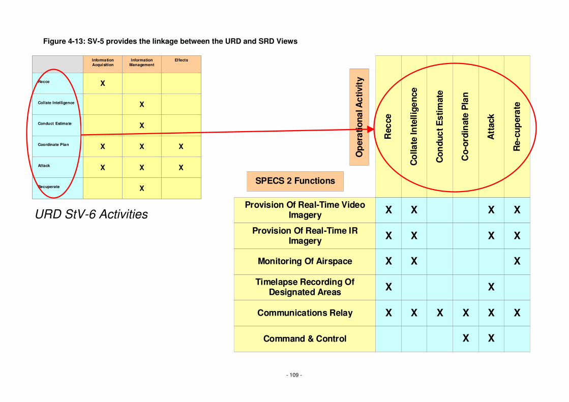
- 109 -
Figure 4-13: SV-5 provides the linkage between the URD and SRD Views
Provision Of Real-Time VideoImagery
Provision Of Real-Time IRImagery
Monitoring Of Airspace
Timelapse Recording OfDesignated Areas
Communications Relay
Command & Control
Rec
ce
Co
llate
Inte
llige
nce
Con
duct
Est
imat
e
Co-
ordi
nat
e P
lan
Att
ack
Re-
cup
erat
e
X X
X X
X X
X
X X X X
X
X
X
X X
X
X X
X X
Op
erat
iona
l Act
ivit
y
SPECS 2 Functions
Information Acquisition
Information Management
Effects
Recce X
Collate Intelligence X
Conduct Estimate X
Coordinate Plan X X X
Attack X X X
Recuperate X
Information AcquisitionInformation AcquisitionInformation Acquisition
Information ManagementInformation
ManagementInformation
ManagementEffectsEffectsEffects
RecceRecceRecce XXX
Collate IntelligenceCollate IntelligenceCollate Intelligence XXX
Conduct EstimateConduct EstimateConduct Estimate XXX
Coordinate PlanCoordinate PlanCoordinate Plan XXX XXX XXX
AttackAttackAttack XXX XXX XXX
RecuperateRecuperateRecuperate XXX
URD StV-6 Activities

- 110 -
Figure 4-14: SV-4 Systems Functional Description
SPECS 2
ISTAR Base Station
Provision OfReal-Time Visual
Imagery
Provision OfReal-Time IR
Imagery
CommunicationsRelay
Monitoring OfAirspace
Command &Control
ManageBandwidth
Rx Orders Tx Orders Process OrdersRecord MessageMeta Dats
ManageBandwidth
Tx Orders Rx Orders
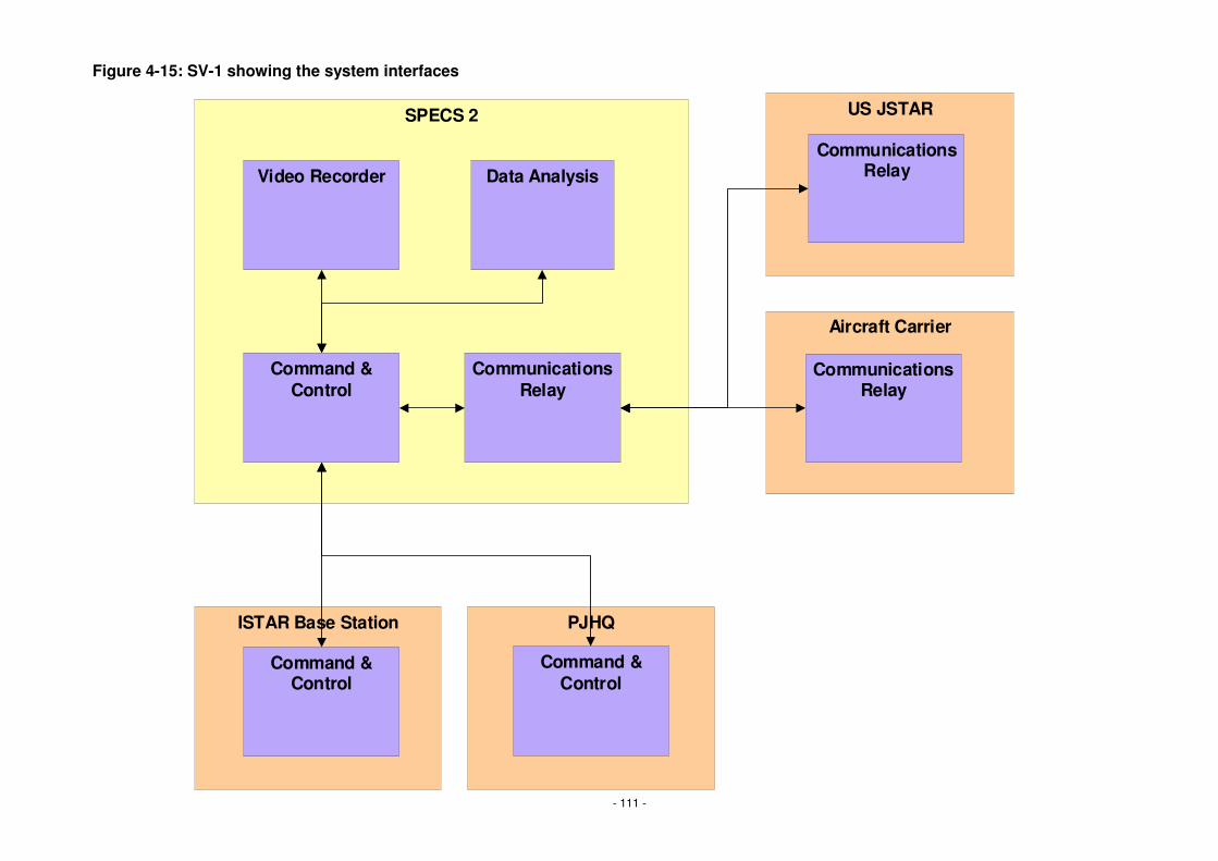
- 111 -
Figure 4-15: SV-1 showing the system interfaces
SPECS 2
Video Recorder
Command &Control
Data Analysis
CommunicationsRelay
ISTAR Base Station
Command &Control
Aircraft Carrier
PJHQ
US JSTAR
CommunicationsRelay
Command &Control
CommunicationsRelay
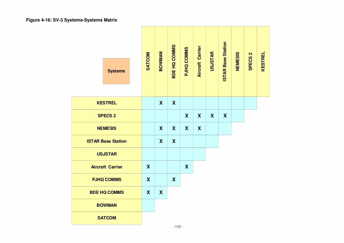
- 112 -
Figure 4-16: SV-3 Systems-Systems Matrix
X
Systems SA
TC
OM
BO
WM
AN
BD
E H
Q C
OM
MS
PJH
Q C
OM
MS
Air
craf
t C
arri
er
ISTA
R B
ase
Sta
tion
NE
ME
SIS
SP
EC
S 2
KE
ST
RE
L
US
JST
AR
SATCOM
BOWMAN
BDE HQ COMMS
PJHQ COMMS
Aircraft Carrier
ISTAR Base Station
NEMESIS
SPECS 2
KESTREL
USJSTAR
X
X
X
X
X
X
X
X
X
X
X
X
X
X
X X X

- 113 -
Figure 4-17: SV-2a for US JSTAR asset
US JSTARInformation
Fusion System
ReceiverPort
ETHERNETLOS COMMS
HTTPTCP/IP
FTPFusion Appl
TransmitterPort
ETHERNETLOS COMMS
HTTPTCP/IP
FTPFusion Appl

- 114 -
Figure 4-18: SV-2a for SPECS 2 SRD
SPECS 2Receiver
SPECS 2Transmitter
ReceiverPort
ETHERNETLOS COMMS
HTTPTCP/IP
TransmitterPort
ETHERNETLOS COMMS
HTTPTCP/IP
Link ApplLink Appl

- 115 -
Figure 4-19: SV-2b System-to-System Protocol Stack
SPECS 2Receiver
SPECS 2Transmitter
ReceiverPort
ETHERNETLOS COMMS
HTTPTCP/IP
TransmitterPort
US JSTARInformation
Fusion System
ReceiverPort
TransmitterPort
ETHERNETLOS COMMS
HTTPTCP/IP
SPECS 2 Transmitt
SPECS 2 Receive
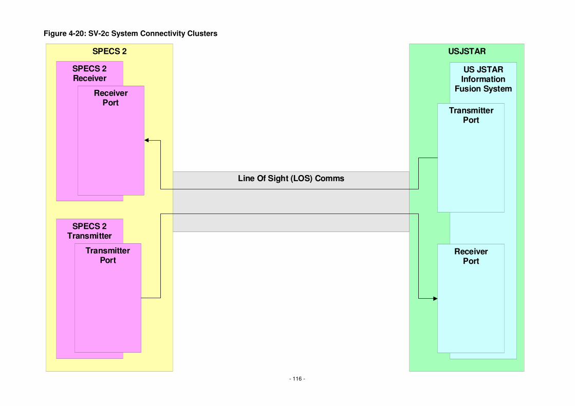
- 116 -
Figure 4-20: SV-2c System Connectivity Clusters
Line Of Sight (LOS) Comms
SPECS 2 USJSTAR
SPECS 2Receiver
SPECS 2Transmitter
ReceiverPort
TransmitterPort
US JSTARInformation
Fusion System
ReceiverPort
TransmitterPort
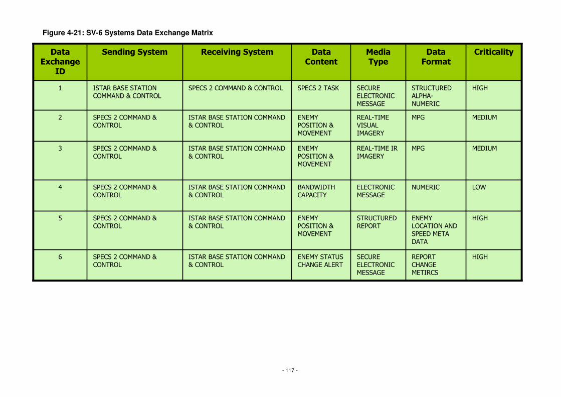
- 117 -
Figure 4-21: SV-6 Systems Data Exchange Matrix
�����������������������
����������������
�����������������
�����������
�������
���������������
�������
����������������
�������
���������
������� �����������
�����������������������������
�������
���
���
������������� ��
�������
����� ����
�� ������������ ���������
�����!�����������������"�������
�����#�������"�������
$
�� �������������"��������
�����!�����������������"�������
�����#�������"�������
%
��&!���&��� ��������
�����!�����������������"�������
�����#�������"�������
'
�����������
��������"��������
�����!�����������������
"�������
�����#�������"
�������
(
�������������������"
��������
�����!�����������������"�������
�����#�������"�������
#
�� �����#���)�����#�������"������������!�����������������"�������
�
���������������� �����
��������������������������������������������

- 118 -
Figure 4-22: SV-7 System Performance Parameters Matrix
��*+���
*!#,�����-�����.��� �� #/#
�!#��00.�1����-!��*+�* 1�233��
�����#�����-�����..��
(/�
��4�-.�,#'4#,'5��3���*��.�-2 ��������#��*�������*��
'/�
�2�.6 �3���*��.�-2 ���
#,� �������3��� 7 '/#
��8 +���
0� ��.�,����020 ���� -��� ��������*��� ����2���7
��*�����-7.�.��/�
0� ��..��%����020 ���� .3��*���2���7
.����*.
0� ��.
*!
�!
�������
(,����020�-�� ��.3��.� �0�
%,,����020. � 2.�1�����-�� ���2���7
����� � � 2.�-�� ���
��/#
$,���������#�����9�� #/�
#����.0�..����� ������#����.0� �� �/�
���������� ��������� ��������
������!�������������������

- 119 -
Figure 4-23: StV-2 Capability Functions with Performance Attributes
Information Acquisition Information Management Effects
1. StrategicRange: 120km - 1000kmDuration: 24hrs
1. Analysis 1. TargetingAccuracy: 10m
2. OperationalRange: 20km - 120kmDuration: 20hrs
2. Fusion 2. Plan Engagement
3. TacticalRange: 0km - 20kmDuration: 16hrs
3. Quality Assurance 3. Conduct Engagement
4. Dissemination 4. Battle Damage Assessment
Information AcquisitionInformation AcquisitionInformation Acquisition Information ManagementInformation ManagementInformation Management EffectsEffectsEffects
1. StrategicRange: 120km - 1000kmDuration: 24hrs
1. StrategicRange: 120km - 1000kmDuration: 24hrs
1. Analysis1. Analysis 1. TargetingAccuracy: 10m1. TargetingAccuracy: 10m
2. OperationalRange: 20km - 120kmDuration: 20hrs
2. OperationalRange: 20km - 120kmDuration: 20hrs
2. Fusion2. Fusion 2. Plan Engagement2. Plan Engagement
3. TacticalRange: 0km - 20kmDuration: 16hrs
3. TacticalRange: 0km - 20kmDuration: 16hrs
3. Quality Assurance3. Quality Assurance 3. Conduct Engagement3. Conduct Engagement
4. Dissemination4. Dissemination 4. Battle Damage Assessment4. Battle Damage Assessment

- 120 -
Figure 4-24: StV-3 Capability Phasing
Capability Functions Epoch 1 Epoch 2 Epoch 3
Information Acquisition
Strategic ISTAR NEMESIS NEMESIS
Operational ISTAR SPECS SPECS 2 SPECS 2
Tactical ISTAR LOOKER KESTREL KESTREL
Information Management
Analysis NEMESIS NEMESISISTAR BASE STATION
ISTAR BASE STATION
Fusion NEMESIS NEMESISISTAR BASE STATION
ISTAR BASE STATION
Quality Assurance NEMESIS NEMESISISTAR BASE STATIN
ISTAR BASE STATION
Dissemination BOWMAN, SAT BOWMAN, SAT
Effects
Targeting LOOKER, SPECS KESTREL, SPECS 2
KESTREL, SPECS 2
Plan Engagement BISA BISA
Conduct Engagement CR2, MILAN, FGA CR2, FGA CR2, FGA
BDA FGA, SAT FGA, SAT FGA, SAT
Capability FunctionsCapability FunctionsCapability Functions Epoch 1Epoch 1Epoch 1 Epoch 2Epoch 2Epoch 2 Epoch 3Epoch 3Epoch 3
Information AcquisitionInformation Acquisition
Strategic ISTARStrategic ISTAR NEMESISNEMESISNEMESIS NEMESISNEMESISNEMESIS
Operational ISTAROperational ISTAR SPECSSPECSSPECS SPECS 2SPECS 2SPECS 2 SPECS 2SPECS 2SPECS 2
Tactical ISTARTactical ISTAR LOOKERLOOKERLOOKER KESTRELKESTRELKESTREL KESTRELKESTRELKESTREL
Information ManagementInformation Management
AnalysisAnalysis NEMESISNEMESISNEMESIS NEMESISISTAR BASE STATION
NEMESISISTAR BASE STATION
NEMESISISTAR BASE STATION
ISTAR BASE STATIONISTAR BASE STATIONISTAR BASE STATION
FusionFusion NEMESISNEMESISNEMESIS NEMESISISTAR BASE STATION
NEMESISISTAR BASE STATION
NEMESISISTAR BASE STATION
ISTAR BASE STATIONISTAR BASE STATIONISTAR BASE STATION
Quality AssuranceQuality Assurance NEMESISNEMESISNEMESIS NEMESISISTAR BASE STATIN
NEMESISISTAR BASE STATIN
NEMESISISTAR BASE STATIN
ISTAR BASE STATIONISTAR BASE STATIONISTAR BASE STATION
DisseminationDissemination BOWMAN, SATBOWMAN, SATBOWMAN, SAT BOWMAN, SATBOWMAN, SATBOWMAN, SAT
EffectsEffects
TargetingTargeting LOOKER, SPECSLOOKER, SPECSLOOKER, SPECS KESTREL, SPECS 2
KESTREL, SPECS 2
KESTREL, SPECS 2
KESTREL, SPECS 2
KESTREL, SPECS 2
KESTREL, SPECS 2
Plan EngagementPlan Engagement BISABISABISA BISABISABISA
Conduct EngagementConduct Engagement CR2, MILAN, FGACR2, MILAN, FGACR2, MILAN, FGA CR2, FGACR2, FGACR2, FGA CR2, FGACR2, FGACR2, FGA
BDABDA FGA, SATFGA, SATFGA, SAT FGA, SATFGA, SATFGA, SAT FGA, SATFGA, SATFGA, SAT
SPECS 2 must interoperate with both the NEMESIS ISTAR Base Station in Epoch 2, and the ISTAR Base Station in Epoch 3

- 121 -
Figure 3-25: SV-8 Systems Evolution Description
Service Orientated Networking
Virtual Networks (including VLAN)
Fixed Point To Point Networks
Networking philosophy
XP
Medium Term3-6 years
Not disclosedXPWindows Version
180GB60GBDefault storage capacity for Personal Computer
10Ghz Processor2Ghz ProcessorDefault digital signal processor speeds
Long Term6-9 years
Short Term1-3 years
Area

- 122 -
Figure 4-26: TV-2 Technical Standards Forecast
WAN: SDH TechnologyLAN: Gigabit Ethernet Backbone
XMIv2.1
Medium Term3-6 years
WAN: PDH TechnologyMOD Communications/ Networking Policy
MOD System Of Systems Engineering Management Plan (SEMP)
Local Systems Engineering Management Plan (SEMP)
MOD Systems Engineering Standards
MODAF v2.0MODAF v1.0XMI v2.0
MODAF
Long Term6-9 years
Short Term1-3 years
Standard/ Policy

- 123 -
Figure 4-27: Modified OV-1c after industry consultation
15510152530Maximum time delay (seconds) viewing tasked location
SPECS 2 Video Delay
55567810Number of days required for maintenance
SPECS 2 Downtime
6444422Number of individual video channels provided
SPECS 2 Video Support
300
24
2027
300
36
2028
500
36
2029
600
36
2030
SPECS 2 Range
SPECS 2 Flight Time
Attribute
300
24
2026
1200300Maximum number of km from ISTAR base station
4824Maximum number of hours for a single flight
Target2025Measure
15510152530Maximum time delay (seconds) viewing tasked location
SPECS 2 Video Delay
55567810Number of days required for maintenance
SPECS 2 Downtime
6444444Number of individual video channels provided
SPECS 2 Video Support
300
24
2027
300
36
2028
500
36
2029
600
36
2030
SPECS 2 Range
SPECS 2 Flight Time
Attribute
300
20
2026
1200300Maximum number of km from ISTAR base station
4820Maximum number of hours for a single flight
Target2025Measure

- 124 -
Figure 4-28: SV-8 Systems Evolution Description
Release 1
SPECS 2
Release 2 Release 3 Release 4 DisposalPlanning
Q1 2025 Q2 2026 Q4 2028 Q4 2030 Q4 2040
InitialRelease Release +
UrgentAdditionalRequirementsIdentified AtAcceptance
Release + DesirableAdditional RequirementsIdentified At Acceptance Release + Required
Situational Updates Planning for disposal/exension of designed life
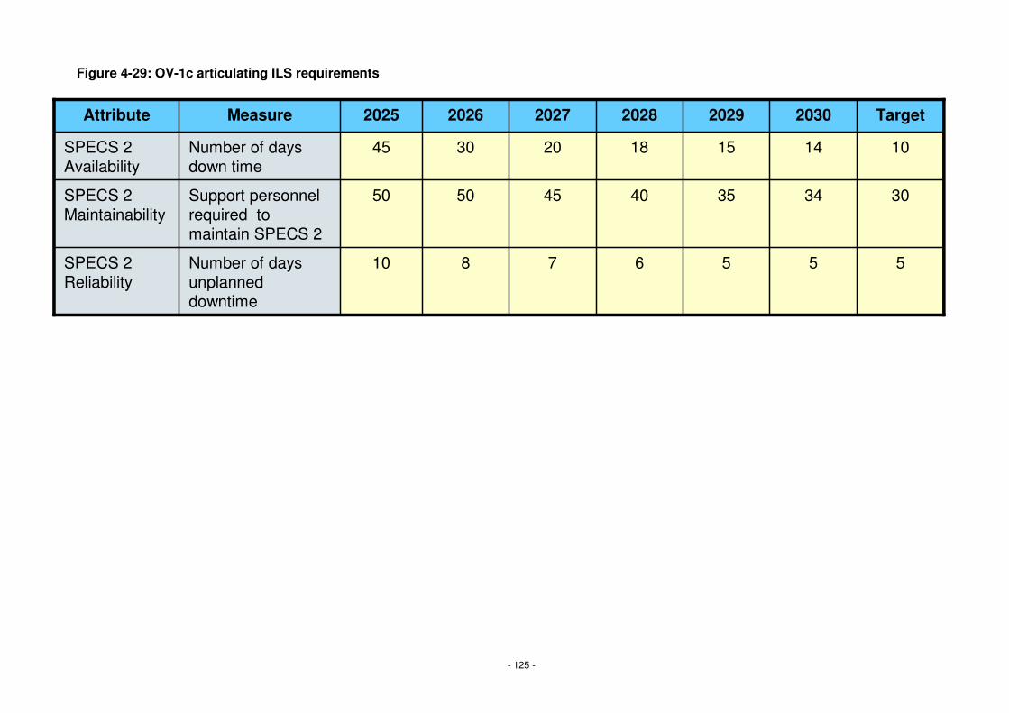
- 125 -
Figure 4-29: OV-1c articulating ILS requirements
7
45
20
2027
6
40
18
2028
5
35
15
2029
5
34
14
2030
SPECS 2 Reliability
SPECS 2 Maintainability
SPECS 2 Availability
Attribute
8
50
30
2026
510Number of days unplanned downtime
3050Support personnel required to maintain SPECS 2
1045Number of days down time
Target2025Measure
7
45
20
2027
6
40
18
2028
5
35
15
2029
5
34
14
2030
SPECS 2 Reliability
SPECS 2 Maintainability
SPECS 2 Availability
Attribute
8
50
30
2026
510Number of days unplanned downtime
3050Support personnel required to maintain SPECS 2
1045Number of days down time
Target2025Measure
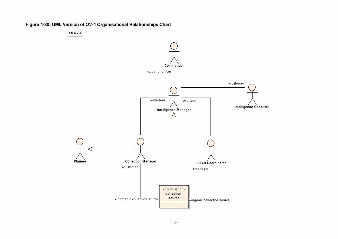
- 126 -
Figure 4-30: UML Version of OV-4 Organisational Relationships Chart
cd OV-4
Collection Manager ISTAR Coordinator
Intelligence Manager
Commander
Intelligence Consumer
Planner
«organisation»collection
source
+superior officer
+manager
+organic col lection source
+customer
+inorganic col lection source
+customer
+overseer+overseer

- 127 -
Figure 4-31: UML Use Cases derived from the OV-4
ud Use Case Diagram
Collection Manager
Maintain Collection Plan
Generate RFI
Task Organic Collection Sources
Monitor Organic Collection Sources
ISTAR Coordinator
Intelligence Manager
Monitor ISTAR Process
Identify Information Collection
Requirements
Deceminate Intelligence
Commander
Specify Directiv es
Intelligence Consumer
Receiv e Intelligence
Collect Organic Intelligence
Collect Inorganic Intelligence
«organisation»collection
source
«extend»
«extend»
«extend»

- 128 -
Figure 4-32: UML representation of an OV-5 Operational Activity Model
ad Activ ity Diagram
ISTA
R C
oord
inat
orC
olle
ctio
n M
anag
erIdentify
Information Collection
Requirements
:Intelligence Collection Plan
Determine how information can
be collected
Identify required
collection capability
Allocate capability
to task
:Battlespace Management
Information Source
Identify w hat information should
be collected
Identify w hen information needs to be
collected
Raise RFI
:Intelligence Estimate
:IPB
Monitor Task
Update plan
RFI
Update Plan
Monitor Response
Notify Intelligence
Manager
:Intelligence Collection Plan
Notify Intelligence Manager and Collection
M anager
[inorganic]
[organic]
[else]
[does not meetrequirement]
[else]
[does not meetrequirement]

- 129 -
Figure 4-33: UML representation of a hybrid SV-4 Systems Functionality Description
ad SV4S
ituat
ion
Aw
aren
ess
Sys
tem
ISTA
R S
yste
mIS
TAR
Coo
rdin
ator
Col
lect
ion
Man
ager
Display Collection
Requirements
Input collection
Tasks
Update Task List
Display Task List
Prov ide Geographical
information
Display Geographical
Locations
battlespace topography
Select Geographical
Location corrisponding
to task
Display av ailable
assetsRequest Geographical
Information
Prov ide av ailable
asstes
Request assets for
geographical location
asset list[fi l tered]
Display task list M ap
Assets to Tasks
Allocate Assets to
Tasks
Update collection
plan
Update asset status
Design Consideration:These two exchanges could be achived wi thin a single exchange.

- 130 -
A.4 Other Deskbook Figures
The following pages contain all the other Figures used to illustrate the text, enlarged for readability if they are not easily readable within the text.

- 131 -
Figure 2-1: MODAF Viewpoints
SystemsViewpoint
Articulates system composition and interconnectivity to support system
analysis, and through-life management
Acquisition Viewpoint
Articulates acquisition programme construct, timelines and DLOD status to
inform planning
All Views
Provides pertinent summary information that specifies the architecture product
Strategic Viewpoint
Articulates the long-term strategic picture to support capability management and
equipment planning
TechnicalViewpoint
Articulates policy, standards, guidance & constraints to specify and assure quality
expectations
Operational Viewpoint
Articulates the operational picture to support operational analysis, user requirements
definition, and solution acceptance

- 132 -
Figure 2-2: MODAF 1.0 Baseline Products
TaxonomyTaxonomy
Meta ModelMeta Model
MODAF Acronyms ListMODAF Acronyms List
COI COI DeskboDeskbo
okok
COI COI DeskboDeskbo
okok
AcquisitionAcquisitionDeskbookDeskbook
COI COI DeskboDeskbo
okok
COI COI DeskboDeskbo
okok
MODAFMODAFCOICOI
DeskbookDeskbook
MODAFMODAF
Technical Technical HandbookHandbook
MODAFMODAF
OverviewOverview
MODAF Executive SummaryMODAF Executive Summary
ViewViewOverviewOverview
ViewViewOverviewOverview
MODAF Glossary of TermsMODAF Glossary of Terms

- 133 -
Figure 2-3: Community of Interest Deskbook Scope
C A D M C A D M I T
D I
Concepts & Doctrine
Capability
Management
Operations
Funded Options
Capability Gaps Future Op
Needs
Doctrine
Customer 1 Acquisition
Sustainment
Customer 2
Concepts & Doctrine
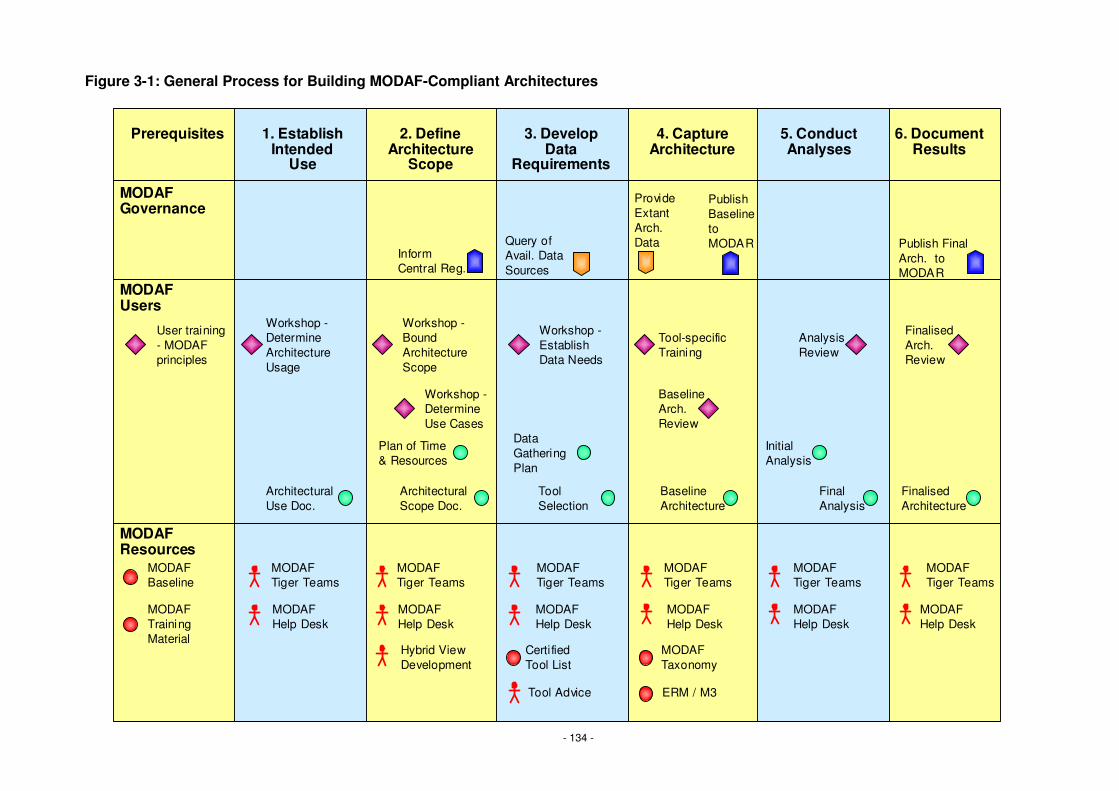
- 134 -
Figure 3-1: General Process for Building MODAF-Compliant Architectures
User training- MODAF principles
Prerequisites 1. Establish Intended
Use
2. Define Architecture
Scope
3. Develop Data
Requirements
4. Capture Architecture
5. Conduct Analyses
6. Document Results
MODAF Governance
MODAF Users
MODAF Resources
MODAF Baseline
Architectural Use Doc.
Workshop -Determine Architecture Usage
Workshop -Bound Architecture Scope
Workshop -Establish Data Needs
Architectural Scope Doc.
Tool Selection
Data Gathering Plan
BaselineArch. Review
Baseline Architecture
Inform Central Reg.
Query of Avail. Data Sources
Publish Baseline to MODAR
Tool-specific Training
Initial Analysis
Final Analysis
Analysis Review
Finalised Architecture
Finalised Arch. Review
Publish Final Arch. to MODAR
Provide Extant Arch.Data
MODAF Training Material
MODAF Tiger Teams
MODAF Tiger Teams
MODAF Help Desk
MODAF Help Desk
MODAF Help Desk
MODAF Help Desk
MODAF Help Desk
MODAF Help Desk
MODAF Tiger Teams
Certified Tool List
Tool Advice
Hybrid View Development
MODAF Tiger Teams
MODAF Tiger Teams
MODAF Tiger Teams
MODAF Taxonomy
ERM / M3
Workshop -Determine Use Cases
Plan of Time & Resources

- 135 -
Figure 3-2: Key Elements and Interfaces of Acquisition COI Processes
Acquisition
I T
DI
Concepts & Doctrine
Capability
Management
Operations
C A D M
C A D M
Acquisition
Project Management
Requirements
Systems / Technology
Industry
Through Life Management
URD SRD
CapabilityTLMP
CONOP,CONEMP,CONUSE CIP
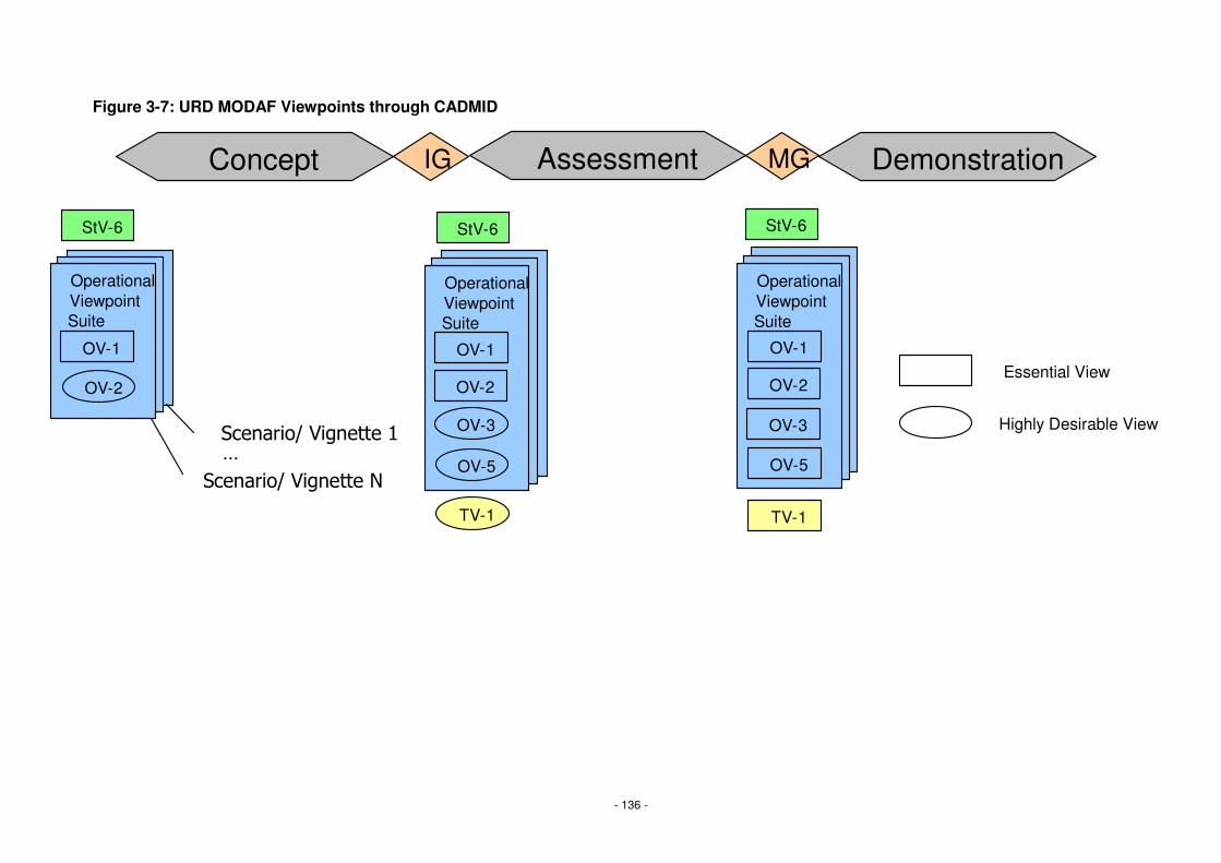
- 136 -
Figure 3-7: URD MODAF Viewpoints through CADMID
IG MG
TV-1
OV-2
OV-1
OV-3
OV-5
Operational Viewpoint Suite
StV-6
OV-1
Operational Viewpoint Suite
OV-2
OV-1
Operational Viewpoint Suite
OV-5
TV-1
OV-3
OV-2
Assessment DemonstrationConcept
������������� ��
������������� ��
�
StV-6 StV-6
Essential View
Highly Desirable View
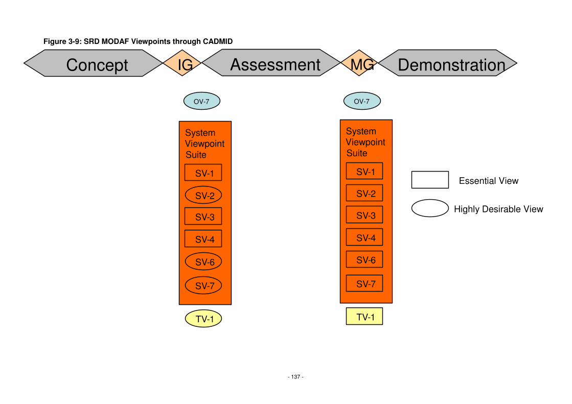
- 137 -
Figure 3-9: SRD MODAF Viewpoints through CADMID
IG MG
TV-1
SV-3
SV-1
System Viewpoint Suite
SV-6
TV-1
SV-2
Assessment DemonstrationConcept
SV-4
SV-7
SV-3
SV-1
System Viewpoint Suite
SV-4
SV-2
SV-6
SV-7
Essential View
Highly Desirable View
OV-7 OV-7

- 138 -
Figure 3-24: TLMP MODAF Views through CADMID
IG MG
SV-9
AcV-2
SV-8
Assessment DemonstrationConcept
SV-9
SV-8
AcV-2
SV-9
SV-8
AcV-2
Essential View
Highly Desirable View