
Mobile parallel robot for carrying out welding and ... · 1.2.1 Kinematics of parallel manipulators...
45
Pekka Pessi NOVEL ROBOT SOLUTIONS FOR CARRYING OUT FIELD JOINT WELDING AND MACHINING IN THE ASSEMBLY OF THE VACUUM VESSEL OF ITER Thesis for the degree of Doctor of Science (Technology) to be presented with due permission for public examination and criticism in the Auditorium 1383 at Lappeenranta University of Technology, Lappeenranta, Finland on the 18th of December, 2009, an noon. Acta Universitatis Lappeenrantaensis 377
Transcript of Mobile parallel robot for carrying out welding and ... · 1.2.1 Kinematics of parallel manipulators...

Pekka Pessi NOVEL ROBOT SOLUTIONS FOR CARRYING OUT FIELD JOINT WELDING AND MACHINING IN THE ASSEMBLY OF THE VACUUM VESSEL OF ITER
Thesis for the degree of Doctor of Science (Technology) to be
presented with due permission for public examination and criticism in the Auditorium 1383 at Lappeenranta University of Technology, Lappeenranta, Finland on the 18th of December, 2009, an noon.
Acta Universitatis Lappeenrantaensis 377
������������������� �� ����������

Supervisor Professor Heikki Handroos Faculty of Technology Department of Mechanical Engineering Lappeenranta University of Technology Finland Reviewers Professor Emeritus Ken Ichiryu
Director of Monodukuri-mekatoro Laboratory Kikuchi Manufacturing Company
Japan Professor Michael Rygaard Hansen
Department of Engineering University of Agder Norway
Opponents Professor Emeritus Ken Ichiryu
Director of Monodukuri-mekatoro Laboratory Kikuchi Manufacturing Company
Japan Professor Michael Rygaard Hansen
Department of Engineering University of Agder Norway
ISBN 978-952-214-886-5
ISBN 978-952-214-887-2 (PDF)
ISSN 1456-4491
Lappeenrannan teknillinen yliopisto
Digipaino 2009

Abstract Pekka Pessi Novel Robot Solutions for Carrying out Field Joint Welding and Machining in the Assembly of the Vacuum Vessel of ITER Lappeenranta, 2009 45 p. Acta Universitatis Lappeenrantaensis 377Dissertation. Lappeenranta University of Technology ISBN 978-952-214-886-5, ISBN 978-952-214-887-2 (PDF) ISSN 1456-4491 It is necessary to use highly specialized robots in ITER (International Thermonuclear Experimental Reactor) both in the manufacturing and maintenance of the reactor due to a demanding environment. The sectors of the ITER vacuum vessel (VV) require more stringent tolerances than normally expected for the size of the structure involved. VV consists of nine sectors that are to be welded together. The vacuum vessel has a toroidal chamber structure. The task of the designed robot is to carry the welding apparatus along a path with a stringent tolerance during the assembly operation. In addition to the initial vacuum vessel assembly, after a limited running period, sectors need to be replaced for repair. Mechanisms with closed-loop kinematic chains are used in the design of robots in this work. One version is a purely parallel manipulator and another is a hybrid manipulator where the parallel and serial structures are combined. Traditional industrial robots that generally have the links actuated in series are inherently not very rigid and have poor dynamic performance in high speed and high dynamic loading conditions. Compared with open chain manipulators, parallel manipulators have high stiffness, high accuracy and a high force/torque capacity in a reduced workspace. Parallel manipulators have a mechanical architecture where all of the links are connected to the base and to the end-effector of the robot. The purpose of this thesis is to develop special parallel robots for the assembly, machining and repairing of the VV of the ITER. The process of the assembly and machining of the vacuum vessel needs a special robot. By studying the structure of the vacuum vessel, two novel parallel robots were designed and built; they have six and ten degrees of freedom driven by hydraulic cylinders and electrical servo motors. Kinematic models for the proposed robots were defined and two prototypes built. Experiments for machine cutting and laser welding with the 6-DOF robot were carried out. It was demonstrated that the parallel robots are capable of holding all necessary machining tools and welding end-effectors in all positions accurately and stably inside the vacuum vessel sector. The kinematic models appeared to be complex especially in the case of the 10-DOF robot because of its redundant structure. Multibody dynamics simulations were carried out, ensuring sufficient stiffness during the robot motion. The entire design and testing processes

of the robots appeared to be complex tasks due to the high specialization of the manufacturing technology needed in the ITER reactor, while the results demonstrate the applicability of the proposed solutions quite well. The results offer not only devices but also a methodology for the assembly and repair of ITER by means of parallel robots. Keywords: ITER, vacuum vessel, IWR, parallel link mechanism, Penta-WH. UDC 621.865.8 : 621.791 : 621.039.6

Acknowledgements I would like to express my gratitude to Professor Heikki Handroos for offering the possibility to participate in this research project. The great influence of Professor Huapeng Wu on this work is undeniable. Huapeng’s insights and ideas were magnificent throughout the development process of the device. The supervision and guidance of both professors enabled me to finish this thesis. The efforts of the companies Imatran Kone and Hytar should be mentioned. Their accurate work provided the prototype to the laboratory of the Institute of Mechatronics and Virtual Engineering at Lappeenranta University of Technology. All of the colleagues in the Institute of Mechatronics and Virtual Engineering deserve a special acknowledgement for their support and making the work environment pleasant. I express my gratitude to the reviewers, Professor Emeritus Ken Ichiryu from the Kikuchi Manufacturing Company and Professor Michael Rygaard Hansen from the University of Agder, for their valuable comments and their sincere interest in this work. I greatly appreciate the opportunity to participate in the seminars organized by the Graduate School CE Tampere. They proved very useful in writing this thesis. I appreciate the financial support provided by the South Karelia Regional Fund of the Finnish Cultural Foundation. Lastly, I am especially grateful to my children for their cheerfulness and candour. Lappeenranta, December 2009 Pekka Pessi


Contents
Acknowledgements.................................................................................................................5 Contents..................................................................................................................................7 List of publications.................................................................................................................9 Nomenclature .......................................................................................................................10 1 Introduction.............................................................................................................13 1.1 ITER and the Assembly Problem..............................................................................13 1.2 Parallel Robotics (overview of research carried out by other researchers) ..................14
1.2.1 Kinematics of parallel manipulators........................................................................15 1.2.2 Workspace Analysis ...............................................................................................18 1.2.3 Singularity Analysis ...............................................................................................19 1.2.4 Stiffness Analysis ...................................................................................................19
1.3 Scope of the Work and Outline of the Thesis ............................................................20 1.4 Contribution of the work...........................................................................................20
2 Design considerations of the robot ..........................................................................21 2.1 Definition of the task for the robot ............................................................................21 2.2 Requirements ...........................................................................................................22
2.2.1 6 DOF for assembly and maintenance when track mounted on the seam..................23 2.2.2 10 DOF for assembly and maintenance when track mounted beside the seam..........23
2.3 Possible solutions .....................................................................................................23 2.3.1 6-DOF robot...........................................................................................................24 2.3.2 10-DOF robot .........................................................................................................25
3 Kinematical and static analysis ...............................................................................28 3.1 Kinematic analysis of the 5-DOF IWR......................................................................28 3.2 Force and stiffness analysis of the 5-DOF IWR.........................................................30 3.3 Kinematic analysis of the 10-DOF hybrid manipulator..............................................32
3.3.1 Forward kinematics ................................................................................................32 3.3.2 Inverse kinematics of the robot ...............................................................................33
4 Optimization of the structure by using the multibody simulation approach.........35 5 Machining force analysis .........................................................................................36 6 Simulations and Experiments..................................................................................38 6.1 Static load simulation ...............................................................................................38 6.2 Dynamic machining simulation.................................................................................39 6.3 Experiments with a real prototype.............................................................................40
6.3.1 Control of the 6-DOF robot ....................................................................................40 6.3.2 Control of hydraulic cylinders ................................................................................41 6.3.3 Control of 10-DOF hybrid manipulator...................................................................42
7 Conclusions ..............................................................................................................43 References ............................................................................................................................44 Publications ..........................................................................................................................47


List of publications The thesis consists of the following scientific journal articles: Publication I Huapeng Wu, Heikki Handroos, Pekka Pessi, Juha Kilkki, Lawrence Jones, 2005. Development and control towards a parallel water hydraulic weld/cut robot for machining processes in ITER vacuum vessel, Fusion Engineering and Design, 75–79 (2005), pp. 625–631. Publication II Pekka Pessi, Huapeng Wu, Heikki Handroos, Lawrence Jones, 2007. A mobile robot with parallel kinematics to meet the requirements for assembling and machining the ITER vacuum vessel, Fusion Engineering and Design, 82 (2007), pp. 2047–2054. Publication III Huapeng Wu, Heikki Handroos and Pekka Pessi, 2008. Mobile parallel robot for assembly and repair of ITER vacuum vessel, Industrial Robot: An International Journal, 35/2 (2008), pp. 160–168. Publication IV Yongbo Wang, Pekka Pessi, Huapeng Wu, Heikki Handroos, 2009. Accuracy analysis of hybrid parallel robot for the assembling of ITER, Fusion Engineering and Design, 84 (2009), pp. 1964-1968.

Nomenclature Abbreviations ADAMS automatic dynamic analysis of mechanical systems ANSYS analysis system CNC computerized numerical control DOF degree of freedom FE finite element ITER international thermonuclear experimental reactor IWR intersector weld/cut robot MBS multibody system VV vacuum vessel Symbols a position vector Aa position vector in the coordinate frame A ae cutting depth ap thickness of cutting tool b position vector Bb position vector in the coordinate frame B c cosine Dc diameter of cutting tool F force vector Fc main machining force Ft thrust machining force fi degrees of relative motion permitted by joint i fz chip thickness h offset J jacobian matrix j number of joints in a mechanism K stiffness matrix k stiffness constant kc specific cutting force L length n number of links in a mechanism n rotation speed q vector of a limb q length of a limb R rotation matrix R radius of cutting tool r vector s unit vector s sine

T transformation matrix vc cutting speed vf feed speed X, Y, Z given coordinates z number of teeth Greek letters
, rotation angles rake angle of teeth friction angle phase angle
degree of freedom sum , , rotation angles angular velocity


13
1 Introduction
1.1 ITER and the Assembly Problem The international thermonuclear experimental reactor (ITER) is a joint international research and development project that aims to demonstrate the scientific and technical feasibility of fusion power. It is a part of a research program aimed at demonstrating the technologies essential to a fusion power reactor and testing of critical components required to enable fusion energy to be utilized for future power production. The ITER vacuum vessel has a toroidal chamber structure, which is named as tokamak. The tokamak was first developed in the Soviet Union in the early 1960s, the name “tokamak” being formed from the Russian words toroidalnaya kamera and magnitnaya katushka meaning “toroidal chamber” and “magnetic coil”. The advantage of toroidal, as opposed to linear, geometry is obvious from the avoidance of “ends”. The simplest magnetic field in a torus would be a purely toroidal magnetic field in which all the field lines form circles passing round the torus. [17]
Figure 1 The ITER device
This work is a part of a research program which has been focusing on the joining technologies required to assemble vacuum vessel (VV) of ITER. Sectors of the vacuum vessel are very large components with high thickness and with complex geometrical features, the cross-section of the sector of the VV is shown in Figure 2. Plasma physics and internal components assembly requires more stringent tolerances than normally expected for the size of structure involved. The height of

14
the VV is about 12 meters and diameter is about 19 meters. Overall assembly tolerances are expected to be within 10 mm ( 5 mm) in the whole vacuum vessel.
Figure 2 The D-shaped design of the toroidal field coils. The magnetic force toward the central axis is carried on the primary winding, and the shape was chosen to eliminate bending forces.
1.2 Parallel Robotics (overview of research carried out by other researchers)
Parallel manipulators have a specific mechanical architecture where all of the links are connected both at the base and at the gripper of the robot. This structure has closed-loop kinematic chains in the mechanism; this factor gives advantages in accuracy and rigidity. This kind of manipulator has a better positioning ability than the classical robot or serial manipulator. The high stiffness and low inertia characteristics of the parallel kinematic architecture make it suitable for high-speed machine tools. The definition for a robot according to the Robotics Institute of America is: “A robot is a re-programmable multi-functional manipulator designed to move material, parts, tools, or specialized devices, through variable programmed motions for the performance of a variety of tasks.” The definition includes mechanical manipulators, numerical control machines, walking machines, and the humanoids of science fiction. Most industrial robots are mechanical manipulators [16]. A mechanism or mechanical manipulator is made up of several links connected by joints. In the case of one actuator by link we have a so-called “fully parallel” manipulator (Figure 3). The first one of this type of manipulator was designed for testing tyres [15], but the main use of this mechanical architecture consists in the flight simulator. [10] Links in a mechanism are connected in pairs or by joints. The most frequently used joints are revolute, prismatic, cylindrical, spherical, universal, plane, gear and cam. A kinematic chain is an

15
assemblage of links that are connected by joints. When every link in a kinematic chain is connected to every other link by at least two distinct paths, the kinematic chain forms one or more closed loops and is called a closed-loop chain, which is the characteristic of the parallel mechanism. The number of degrees of freedom (DOF) of a mechanism depends on the number of links and joints and the types of joints used for the construction of the mechanism. Most of the 6-DOF parallel manipulators consist of six extensible limbs. These parallel manipulators possess the advantages of high stiffness, low inertia, and large payload capacity. However, they suffer from the problems of a relatively small useful workspace. Furthermore, their direct kinematics is a very difficult problem.
Figure 3 Fully parallel manipulator [10]
1.2.1 Kinematics of parallel manipulators Parallel manipulators have a specific mechanical architecture where all of the links are connected both at the base and at the gripper of the robot. By changing the lengths of these links, it is possible to control the position of the gripper. Parallel manipulators can be classified into symmetrical and asymmetrical. A manipulator is said to be symmetrical if it satisfies the following conditions:
1. The number of limbs is equal to the number of degrees of freedom of the moving platform. 2. The type and number of joints in all the limbs are arranged in an identical pattern. 3. The number and location of actuated joints in all the limbs are the same.
When the conditions above are not satisfied, the manipulator is called asymmetrical [16]. The number of the degrees of freedom can be calculated by the Grübler or Kutzbach criterion:
iifjnF 1 , (1)
where is the degrees of freedom of the space in which a mechanism is intended to function
n is the number of links in a mechanism, including the fixed link

16
j is the number of joints in a mechanism, assuming that all of the joints are binary fi is the degrees of relative motion permitted by joint i.
Inverse kinematics
For inverse kinematics, the position and orientation vector of a reference point in the moving platform is given and the problem is to find the input joint variables. For the purpose of analysis, usually, a fixed coordinate frame is attached to the fixed base and another coordinate frame is attached to the moving platform. In the example of a 3-UPU parallel manipulator (Figure 4) the fixed coordinate frame is A: xyz at point O, and another moving coordinate frame is B: uvw at point P. The ith actuated limb is connected to the moving platform at point Bi and to the fixed base at point Ai. Further, it is assumed that points B1, B2, and B3 lie on the u-v plane at a radial distance of rb from point P. Points A1, A2, and A3 lie on the x–y plane at a radial distance of ra from point O.
Figure 4 3-UPU parallel manipulator [7]
The u and v axes are parallel to the x and y axes of the coordinate frame A because the orientation of the moving platform of the 3-UPU manipulator with respect to the fixed base remains constant in all positions. As shown in Figure 5, the position vectors of points Ai and Bi with respect to frames A and B can be written as

17
Tiyixi
A aaa 0,, , (2)
T
iviuiB
iA bbbb 0,, , (3)
where a leading superscript indicates the coordinate frame with respect to which the vector is expressed. A vector-loop equation can be written for each limb as follows:
iiiii abpsqq , (4)
where qi is the length of the ith limb and si is a unit vector pointing along the direction of the ith limb. Dot-multiplying qi with itself yields
iT
ii epepq 2 , (5)
where ei=ai-bi. We note that ai, bi and, therefore, ei are constant vectors. Expanding the right-hand side of (5) and taking the square root yields
222ziyyixxi pepepq for i=1,2,3. (6)
Hence, corresponding to each given position of the moving platform, there are two possible solutions. However, the negative limb length cannot be obtained without the reassembly of the mechanism.
Figure 5 A typical limb of the 3-UPU manipulator [7]
18
In [6], the closed form solutions for the inverse position, rate and acceleration kinematics of a 6-DOF Stewart platform are presented. The inverse kinematic problem is concerned with the determination of the displacements of the six links and their time derivatives corresponding to a given Cartesian pose of the moving platform in terms of three positional displacements and three Euler angular displacements and their time derivatives. A 3x3 rotation matrix R is used for the mapping between the moving platform coordinate frame and the fixed coordinate frame. The rotation matrix is defined by using Euler angles: R is
cscssc-scccsssccsc
sscsccssscccR
, (7)
where c and s denote cosine and sine respectively. The sequence of rotations of Euler angles ( , , ) is z-x-z in this case.
Forward kinematics
Solving forward kinematics means determining all of the possible poses of the platform for given
joint coordinates. In other words, the forward kinematic problem is to find the postures of the mobile plate for a fixed set of beam lengths. The determination of the direct kinematics of fully parallel manipulators is, in general, a difficult problem, but it has to be solved for any practical use. Direct kinematics involves the resolution of a system of nonlinear equations whose solution may be not unique. Solving forward kinematics is a computational time consuming operation [11], [13]. In the Stewart platform case, it has been shown that the problem has at most 16 solutions if the mobile plate is a triangle as it can be reduced to solving a sixteen order polynomial, which may have effectively 16 real roots. If the articulation points have a different location, there will be at most 40 solutions when either the fixed or the mobile plate is planar. [9] Forward displacement analysis is introduced for a spatial 6-DOF parallel structure manipulator in [1]. The mathematical model consists of 30 equations with which 30 unknown variables can be solved. In the modelling of forward kinematics for the parallel manipulator, each branch is handled separately as a serial manipulator in this paper.
1.2.2 Workspace Analysis The workspace of a mechanism refers to the set of all positions and orientations achievable by the tip frame. In the robotics literature, the workspace is often classified into two components, the reachable and dexterous workspace. The reachable workspace is defined to be the set of points in a physical space that can be reached by the tip (or more precisely, the origin of the tip frame). The dexterous workspace, on the other hand, is the set of points that can be reached with any arbitrary orientation of the tip frame [8]. In [8], the performance of two 6-degree-of-freedom parallel mechanisms is compared: the conventional Stewart platform, and the PRPSx3 mechanism, and a hybrid 6-DOF serial-parallel structure.

19
A workspace of 3-DOF translational parallel manipulators has defined analytically in [5]. The result of this study is that the analytic expression of the surfaces bounding their workspace is a fourth degree polynomial equation, in the coordinates of a platform point, which contains all the manipulator geometric parameters. This analytic expression is given in an explicit form.
1.2.3 Singularity Analysis In general, for a given set of link lengths there is only one position for the gripper. However, it may be suspected that in some cases more than one solution may be found for the position of the
gripper: the robot is in a singular configuration. To determine these singular configurations, the classical method is to find the roots of the determinant of the Jacobian matrix. Singularities are particular configurations where the robot becomes uncontrollable. The singular configurations are determined by the analysis of the rank of the inverse Jacobian, J-1 matrix. There are two kinds of singularities [4]: 1) Singularities of the first type which occur when the determinant of the matrix J-1 becomes
infinite. 2) Singularities of the second type which occur when the determinant of J-1 is equal to zero,
0)(det J . They correspond to an uncontrollable displacement of the mobile part when all of the active links are locked. Such configurations lead to the gain of one or more degrees of freedom. Then, the structure is no longer rigid and along certain directions in the Cartesian space, the device cannot withstand external forces. In this case, the robot may be damaged, and this explains why the determination of these configurations is a crucial problem for practical applications. The corresponding behaviour can be explained from a static equilibrium point of view. Let F be the external force applied to the robot terminal tool, and f be the joint force vector. The static equilibrium induces the following equation:
fTJF 1 , (8)
where J -1 represents the inverse kinematic matrix, xqJ .
The equation above has generally one solution f for every F except in the case where the J-1 matrix is degenerated. In this case, the static equilibrium of the system is no longer obtained and the system becomes uncontrollable.
1.2.4 Stiffness Analysis The determination of the inverse kinematics and Jacobian matrix is needed in defining stiffness properties for a parallel manipulator. The stiffness matrix K is not constant it varies in the workspace. This matrix relates the forces and torques applied at the gripper link in the Cartesian space to the corresponding linear and angular Cartesian displacements:

20
xKF . (9)
This matrix can be obtained using kinematic and static equations. The stiffness matrix is given by the following expression:
JkJK T , (10)
where k is a scalar representing the stiffness of each of the actuators, which are modelled as linear springs [2].
1.3 Scope of the Work and Outline of the Thesis The main objective is to design and produce a robotic system which carries several processes necessary to assemble or remove sectors of the ITER vacuum vessel. In the first step, the dynamic simulation model of the IWR (Intersector Weld/Cut Robot) was built and the dynamic behaviour of the IWR was examined. Several construction configurations were examined by means of virtual prototyping. The new construction, called 5D-IWR, was designed. 5D-IWR has six degrees of freedom, but one degree of freedom is the track motion on the VV wall. The built real prototype has 5 DOF because for that moment it was important to test the statical and dynamical behaviour of the real device with insignificant resources. The design of a new version of IWR with modified requirements had begun after obtaining good results from the 5-DOF real prototype. The new robot has to be able to operate on both sides of the rail track. The workspace dimensions are enlarged from the previous version.
1.4 Contribution of the work The work described in this thesis is a significant step towards the solution for manufacturing of the vacuum vessel of ITER. The thesis proposes two novel parallel kinematic robot constructions and shows their advantages in carrying out the machining tasks required in the assembly of the vacuum vessel of ITER. The solutions include several new ideas and contributions in comparison with existing commercially available solutions. The author joined the project group during the experimental testing of the 5D-IWR and at an early stage of the design of the second version of IWR. The author participated in the major part of the analysis and development work from this point of the project onward. Dynamic simulation models of both versions of the IWR were created. The author was the main contributor to the modeling and simulation work carried out in the paper “A mobile robot with parallel kinematics to meet the requirements for assembling and machining the ITER vacuum vessel”. The behaviour of the robots as complex mechanical systems can be analyzed with a simulation model or virtual prototype. The model consists of rigid and flexible bodies, joint constraints that couple the bodies, and power components such as hydraulic actuators and electrical drives. Before fixing the geometrical design of the robot mechanical system, the flexibilities of the main parts of the robots were optimized by using commercial finite

21
element analysis software. The author influenced all selected structural and kinematic solutions to provide sufficient stiffness properties and workspace and made an important contribution in the final design of the robots, as discussed in the attached publications.
2 Design considerations of the robot
2.1 Definition of the task for the robot The robot has to be able to carry out the assembly and maintenance tasks inside the vacuum vessel of ITER. The VV is composed of nine sectors (Figure 6). This means that nine field joints are used in the assembly of the VV. The reason why it is not possible to use some strong and bulky device is that the assembly and maintenance operations have to be carried out from inside. This is because there are several components such as field coils already mounted on the outer wall of the sectors, as shown in Figure 1. The angle of each sector and field joint is 40°. The assembly and maintenance work has to be completed through ports which are placed on the outer surface of the second wall of the VV, Figure 7 b).
Figure 6 Top view of the vacuum vessel and sector
The vacuum vessel has a double-wall structure. The inner wall is marked with blue color in Figure 7, while the outer wall is marked with orange color.

22
Figure 7 Sector parts of the VV, a) inner shell, b) cross-section, c) outer shell The first step in joining the sectors is making a field joint of the outer wall. Splice plates are used in the field joints to compensate the manufacturing errors of two adjacent sectors. One task for a manipulator is the remote handling of splice plates, which means carrying and putting them into the right position through the gap in the inner wall. The distance between the inner and outer wall varies as shown in Figure 7 b), which further increases the challenge of the assembly task. The splice plates are used also in joining the inner walls of the adjacent sectors. During the assembly welding, a seam tracking device will be used to make a high quality welding joint. The seam tracker is used for obtaining the position and orientation information of the end tip in relation to the seam. The robot as a service machine should be able to machine and reweld defected welds. In addition, a possibility of machining and rewelding flexible houses, which are shown in Figure 7 a) and c), must be provided by the robot.
2.2 Requirements Assembly tolerances are expected to be within 10 mm ( 5 mm) in the whole vacuum vessel. The height of the VV is approximately 12 meters. The sectors of the vacuum vessel are very large components with high wall thickness (60 mm) and with complex geometry. The robot has to be able to complete the initial assembly of the VV. The sectors of the VV are made of stainless steel

23
and are joined together by high efficiency structural and leak-tight welds. In addition to the initial assembly, sectors may have to be replaced for repair.
2.2.1 6 DOF for assembly and maintenance when track mounted on the seam
The initial plan was to mount the robot track on two sectors on both sides of the splice plate. The required workspace of the robot tip end is 200 by 200 by 300 mm in the X-Y-Z coordinate system, respectively, five degrees of freedom (three translations and two rotations) are required for the manipulator itself to carry out welding and machining processes, and the 6th DOF is the carriage motion along the track. The welding seam is planned to be between the rails of the track, so there is no need to rotate the end-effector around the vertical axis. The force acting on the end-effector is smaller during welding than during machining. While welding, the robot must support the welding device that can weight up to 200 kg. The maximum force that affects the robot comes from the machining process. During cutting, the dynamic force can be up to 3000 N. The developed robot has to be able to drive into and out from the VV through a port. The repeatability of the robot should be better than 0.1 mm.
2.2.2 10 DOF for assembly and maintenance when track mounted beside the seam
The original task of the robot was only to carry out welding and machining in the field joint area and it is further extended to a larger area. For assembly and maintenance, high mobility of the robot is required, and the moving domain is enlarged radically. The device could work on both sides of the track on which robot drives. In this case, the robot track is mounted on one side of a sector and the robot has to be able to reach the seam while the distance from the track rail to the seam edge varies 500 mm. In addition to welding and machining, the robot is required to transport splice plates inside the VV. The splice plates have to be adjusted into an accurate position and orientation in a gap between two sectors by the robot; thus six degrees of freedom are needed for the end-effector of the robot. The manipulator will also be used as a service robot. The maintenance includes not only machining and rewelding for the defects caused by the assembly welding, but also includes machining and welding of flexible houses on the inner surface of the VV. Thus, a large workspace and 4 DOFs more are required for the robot: rotation, tracking, linear motion and tilting rotation. The robot’s size cannot exceed the dimensions of the port as the robot goes into and out from the VV through an equatorial port. The opening of the port is about two meters by two meters.
2.3 Possible solutions The proposed solutions are six-degree-of-freedom and ten-degree-of-freedom manipulators with parallel architecture. For maintenance, a six-degree-of-freedom parallel robot is designed in which five degrees of freedom are for a parallel mechanism and one degree for tracking.

24
Moreover, for assembly and maintenance, a ten-degree-of-freedom manipulator with parallel architecture is proposed. It is a hybrid mechanism: four degrees of freedom for a serial link mechanism to enlarge the workspace and six degrees of freedom of a parallel link mechanism for the end-effector. The first version of the robot was chosen to be oil hydraulic to solve the basic problems apparent. The functional properties of a oil hydraulic and water hydraulic robot are very similar, and thus the oil hydraulic power source was chosen for the first prototype because of cost. The final IWR will be equipped with water hydraulic drives since large quantities of leaking oil are not allowed in ITER.
2.3.1 6-DOF robot The first oil-hydraulic demonstrator of the 5-DOF IWR was designed, manufactured and tested at the first step. A new construction for the 5-DOF parallel robot, namely Penta-WH, was invented and tested by virtual prototype. It appeared to provide good stiffness properties. The first version of the robot was chosen to be oil hydraulic to solve the basic problems apparent in a hydraulically driven IWR. The functional properties of an oil hydraulic and water hydraulic robot are very similar, and thus it was relevant to choose oil hydraulics in this development phase because of the cost. The final 5-DOF IWR included a linear track, which is the sixth degree of freedom. The purpose of the first prototype was to design and build an oil hydraulic driven 5-DOF parallel demonstrator IWR with a loading platform, position encoders, load cells, a linear table, machining and welding end-effectors, a seam tracking device and control system plus deflection compensation, and to carry out real machining and welding tests with the demonstrator. Figure 8 shows the 5-DOF parallel robot with a loading platform including two hydraulic force-servo axes equipped with load units.
Figure 8 5-DOF IWR

25
2.3.2 10-DOF robot The 10-degree-of-freedom prototype is equipped with water hydraulic drives since large quantities of oil are not allowed in ITER. The 5-DOF parallel robot was redesigned to satisfy the new requirements for the robot. A new robot with ten degrees of freedom was designed and built, as shown in Figure 9. The robot consists of two relatively independent sub-structures. One is Hexa-WH, a Stewart platform based parallel mechanism driven by six water hydraulic cylinders, which contributes a full six degrees of freedom for end-effector. The other is the carriage which offers another four degrees of freedom for Hexa-WH; the carriage mechanism is introduced in the next section.
Figure 9 Hybrid parallel robot IWR
Six servo controlled hydraulic cylinders are used in parallel mechanism, Hexa-WH. The six cylinders connect the frame and the end-effector to each other (Figure 9). A machining head and welding equipment are mounted on the end-effector. Because of the special shape of the VV, a full six degrees of freedom for the motion for the tool are needed to carry out the welding and machining. Hexa-WH can offer the required accuracy and high force capacity because it is a hydraulically driven mechanism. The six hydraulic cylinders are attached to the base of the parallel manipulator via universal joints. A single hydraulic cylinder is presented in Figure 10.

26
Figure 10 Cylinder of the Hexa-WH
2.3.2.1 The carriage mechanism The carriage mechanism offers four additional degrees of freedom to enlarge the workspace of the parallel manipulator Hexa-WH. The 4 DOFs are tracking motion, linear motion, rotation and tip motion. In total, the robot has ten degrees of freedom. The carriage mechanism itself consists of several units. The carriage frame, Figure 11, is a complex structure welded by multi-steel-plates, and it is able to carry a high payload and offer enough room to maintain other mechanisms. The stiffness and weight are the most important indexes in the design and they have been optimized to achieve the necessary stress with a light weight. Even small deflections of the carriage frame will multiply to the end-effector of the robot because of the distance and many other components.
Figure 11 The carriage frame
The tracking drive unit consists of an electric motor, the reduction unit CYCLO, a V-shaped bearing, and a driving gear. The electric servo motor with a position feedback controller offers highly accurate motion. To output great torque needed to drive the great mass and payload, the

27
reduction unit CYCLO is added to the motor to reduce speed and transmit high torque to the drive gear. Two V-shaped wheels keep the carriage on the tracking rail in the right position to avoid cross motion. Two drive units are used in the carriage to offer enough torque to drive the robot and payload in any position in the VV. The compensation system (Figure 12) is an important unit which limits the backlash caused by inaccurate assembly of the tracking rail, and compensates distance changes between the wheels in the bending area. Travelling along the rail, the wheels of the robot must touch the surface of the tracking rail at all times.
Figure 12 The compensation system
As the shape of the VV is very complicated, the tracking rails lying on the VV surface are very difficult to keep in an accurate position. The position tolerance can be up to ±2 mm, and in addition, the distance of couple wheels is changed in the bending area. During the motion, all of the wheels must touch the parallel rails with a certain force, and thus, an adaptive distance compensation system is need. At the same time, the compensation system should be able to take the entire weight of the robot and payload when the robot is upside down in the top position in the VV. Since the total payload is very high, a hydraulic cylinder is applied to justify the compensating force according to the position where the robot is located. Figure 12 shows the compensation system, the upside is a tolerance adaptive mechanism and the downside is a hydraulic distance compensation system. The linear drive unit enlarges the workspace of the robot. It consists of five parts: a ball screw drive unit, a servo motor, rails, linear bearings, and a table. Two parallel rails are fixed on the carriage frame to offer motion crossing the frame and to extend the distance of the robot in the Y-direction. In this direction, the difference of one VV sector from the inner board to the outer board can be 900 mm. The linear motion helps the robot to reach the far border of the VV. The rotation drive unit offers a rotation motion about the Z-axis, so that the robot can weld and machine on both sides of the rail track. The rotation drive unit consists of a slewing bearing, drive gear, reduction unit, and servo motor. The slewing bearing integrates the bearing and gear together, leading to a compact structure with light weight. The rotation of the unit can reach ±180°. The tip drive unit offers one more rotation for Hexa-WH driven by one servo control hydraulic cylinder to extend the translational motion of the robot in the Z-direction.

28
3 Kinematical and static analysis
3.1 Kinematic analysis of the 5-DOF IWR The kinematic structure of the robot is shown in Figure 13. The robot provides five Cartesian degrees of freedom. The tripod equipped with the center beam uses universal joints in connecting the rams with upplate-1 and the midplate while the center beam is connected with upplate-1 by means of a universal joint and fixed with the midplate. The tripod provides Cartesian X-Y-Z coordinates for the end-effector.
Figure 13 Geometry and kinematics of Penta-WH
The two orientations in the Cartesian frame, i.e. angles around the X- and Y-axes are given by two orientation cylinders (cylinder-2) that are connected with EEplate and upplate-2 by means of universal joints. The EEplate is connected with midplate by means of a universal joint.

29
The kinematical analysis includes workspace, singularity, inverse kinematical and inverse speed analyses. All these models were derived for the robot. The achievable workspace is mainly limited by joint boundaries and upplate-1 and upplate-2 constructions. Quite often there are also in-workspace singularities in parallel robots. By using the notation in Figure 14, the inverse kinematics and inverse speed of the mechanism can be calculated from the following formula
iiiii UUBURUUUUUBL '' , (11) where the rotation matrix R is
coscossincossinsincos0
cossinsinsincosR .
Figure 14 Penta-WH and coordinate system for kinematics analysis
|||| ii LL , where Li is the length of cylinder and the speed is

30
TT ZYXJLLLLL ,,,,,,,, 54321 . (12) The kinematical model presented above is required in the robot control system because it needs the mapping from the Cartesian space to the actuator space. Also by means of the inverse speed model, in-workspace singularities can be studied. When the Jacobian matrix J in the presented formula is singular, the robot is in a singular position and cannot put out any Cartesian force. Only a single in-workspace singularity position is possible in the selected kinematic structure. This happens when the axis of the center beam is in the same plane with plane U´B4B5, or one of cylinder L4 and cylinder L5, or both of these two cylinders are in the same plane with plane U´B4B5. In the selected workspace, this singularity position is far away and has a minor effect on the stiffness. The results of the workspace analysis are shown in Figure 15. The singularity free workspace of Penta-WH is shown in blue color in Figure 15. The workspace boundaries are drawn with red in Figure 15 – the box where the end-effector is operating.
Figure 15 Workspace boundaries and requirements
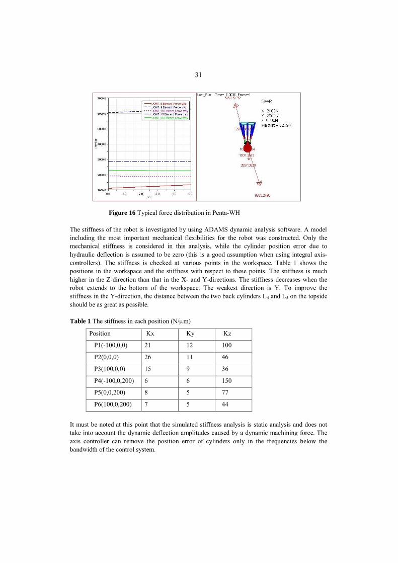
3.2 Force and stiffness analysis of the 5-DOF IWR The stiffness of Penta-WH against static and dynamic forces was investigated. With hydraulic actuators the robot can offer a high payload. Figure 16 shows the typical force distribution in Penta-WH, when the payload affected on the end-effector is F=6633 N (Fx=2000 N, Fy=2000 N, Fz=6000 N).
31
Figure 16 Typical force distribution in Penta-WH
The stiffness of the robot is investigated by using ADAMS dynamic analysis software. A model including the most important mechanical flexibilities for the robot was constructed. Only the mechanical stiffness is considered in this analysis, while the cylinder position error due to hydraulic deflection is assumed to be zero (this is a good assumption when using integral axis-controllers). The stiffness is checked at various points in the workspace. Table 1 shows the positions in the workspace and the stiffness with respect to these points. The stiffness is much higher in the Z-direction than that in the X- and Y-directions. The stiffness decreases when the robot extends to the bottom of the workspace. The weakest direction is Y. To improve the stiffness in the Y-direction, the distance between the two back cylinders L4 and L5 on the topside should be as great as possible. Table 1 The stiffness in each position (N/ m)
Position Kx Ky Kz
P1(-100,0,0) 21 12 100
P2(0,0,0) 26 11 46
P3(100,0,0) 15 9 36
P4(-100,0,200) 6 6 150
P5(0,0,200) 8 5 77
P6(100,0,200) 7 5 44
It must be noted at this point that the simulated stiffness analysis is static analysis and does not take into account the dynamic deflection amplitudes caused by a dynamic machining force. The axis controller can remove the position error of cylinders only in the frequencies below the bandwidth of the control system.

32
3.3 Kinematic analysis of the 10-DOF hybrid manipulator The kinematics of the robot is complicated because of its redundant structure; the kinematics analysis can first be divided into two parts: the carriage and Hexa-WH, and then these two can be combined. The coordinate systems shown in Figure 17 is set up as the following: frame o is fixed on the tracking rail, frame O1 is fixed to the corner of the carriage frame, frame O2 is fixed to the corner of the linear table; frame O3 is fixed at the rotation joint; frame O4 is fixed in the centre of the Hexa-WH frame, and frame O5 is fixed at the center point of the end-effector.
Figure 17 Global coordinate system o(X,Y,Z) and local coordinate systems
3.3.1 Forward kinematics The carriage offers four degrees of freedom for the robot: two linear motions and two rotations. Hexa-WH offers a full six degrees of freedom. Then, the transformation matrix can be defined as:
54321 TTTTTT , (13) Where
1000100010001
1
1
1
1 ZYX
T ,

33
1000100010001
2
2
2
2 ZYX
T ,
100010000
3
3
3
3 ZYcsXsc
T ,
100000
001
4
4
4
4 ZcsYscX
T ,
10005
5
5
5 ZccscsYsccssccssscsXsscsccsssccc
T .
The signs s and c correspond to sine and cosine, respectively, in the matrices T3, T4 and T5. Once the parameters of the joints are given, the forward kinematics of the robot can be defined as
0543210 PTTTTTPTP . (14) To solve the forward kinematics for Hexa-WH, numeric iterative method is employed.
3.3.2 Inverse kinematics of the robot As the robot has four degrees of freedom redundant, we can give an inverse kinematics model to the carriage first, then to Hexa-WH.
3.3.2.1 Inverse kinematics of the carriage The inverse kinematics of the carriage is defined as finding the values of four actuators with respect to the frame o for a given position and an orientation of P4 on Hexa frame. The principle of the carriage mechanism is shown in Figure 18.

34
Figure 18 Scheme of carriage mechanism
In the application the rotation angle is only fixed at a few values, 0°, ±90°, and 180°, and we can calculate values of other actuators by fixing , i.e., for a given position P4 (x,y,z), the center of the Hexa frame, we have
xrrX cos)cos( 10 , (15)
yrrY sin)cos( 10 , (16)
Zr sin1 , (17) Then
)/arcsin( 1rZ , (18)
cos)cos( 10 rrxX , (19)
sin)cos( 10 rryY . (20)
3.3.2.2 Inverse kinematics of Hexa-WH The inverse kinematics for Hexa-WH is defined as finding values for each cylinder for a given position and an orientation of the end-effector with respect to the Hexa frame. Here, O4 coincides with P4 on the carriage side. Figure 19 defines the coordinate of Hexa-WH:

35
Figure 19 Scheme of Hexa-WH
Thus
iii rrROOL '54 (i=1,2,3,4,5,6), (21)
where
ccscs
sccssccssscssscsccsssccc
R .
ir is the vector of the joint of the ith cylinder on the Hexa frame with respect to frame O4, and '
ir is the vector of the joint of the ith cylinder on the end-effector with respect to frame O5. Then, the length of each cylinder can be found when (x, y, z, , , ) is defined with respect to frame O4:
)()( '54
'54 iiiiii rrROOrrROOLl . (22)
4 Optimization of the structure by using the multibody simulation approach
The multibody system (MBS) model is created using MSC.ADAMS software. The model, shown in Figure 20, consists of rigid and flexible parts, and the model of the hydraulic circuit is also included in the MBS model. The flexibility description of some parts is studied with finite

36
element analysis and integrated into the MBS model. The FE analysis is carried out using the ANSYS software. The parts are connected to each other by ideal joints: rotational, universal, spherical, etc. However, the bearings of the linear drive unit are modeled as contact forces instead of using rigid translational joints. In this way the flexibility is described more properly. A control system can be easily tested with a virtual prototype by coupled simulation. The control system modeled with Matlab/Simulink is used. The forces and strokes information of the actuators produced by the MBS model is input for the control system, and output is a control signal for valves.
Figure 20 Multibody system model
5 Machining force analysis Figure 21 shows the machining forces and other important parameters in the machining process.
Figure 21 Cutting tool and machining force

37
The vibration of the robot mostly depends on the machining force, and thus the machining process should be designed such that the robot does not resonate. The formula of the machining force is derived as follows:
pzizizcc ai
RfRtftfkF ))(sin)(sin( 2222 , (23)
)(tanct FF . (24)
The most important parameters that affect the dynamic cutting force are feed speed vf, cutting depth ae, number of teeth z and cutting speed vc. Because of the machinability, work-hardening capability and low thermal conductivity of stainless steel (austenitic), the cutting speed cannot be very high. A sharp tool, a reasonable feed rate and a reasonable depth of cut are recommended. The following values can be recommended: feed rate 0.18 to 0.25 mm (0.18); cutting speed 31 to 157 m/min (60 m/min n = 100 r/min); feed speed 31 to 157 mm/min (100mm/min); cutting depth 10 to 30 mm. The cut frequency is mainly determined by the rotation speed of the tool and number of teeth. The recommended number of teeth is z = 19,5 R -5,8; where R is a tool radius in inches. For R = 100 the number of teeth is close to z = 33. The cutter offset (h) influences the peak value of the cutting force, but not very much compared with the other parameters. Figure 22 shows the dynamic machining force achieved by using the following parameters: Dc = 200 mm, ae = 30mm, z = 30, h = 0, ap = 4.12 mm, kc = 1800 N/mm2, vf = 150 mm/min, n = 100 r/min and cutting frequency = 50Hz. The results are as follows: Max Fcx=617.1N, Min Fcx=398.7N, Max Fcz=228.3N, Min Fcz=91.25N, Max Fc=657.99N, Min Fc=409.07N.

38
Figure 22 Calculated machining force
The results show that further optimization of the tool parameters must be carried out to achieve as small an excitation of vibration in the robot structure as possible.
6 Simulations and Experiments
6.1 Static load simulation The stiffness of the robot is investigated by using ADAMS dynamic analysis software. A model including the most important mechanical flexibilities for the robot was constructed. Only mechanical stiffness is considered in this analysis, while the cylinder position error due to hydraulic deflection is assumed to be zero. The stiffness is checked at various points in the workspace. Table 2 shows the stiffness with respect to the different positions which are plotted by points in the Figure 23.
Table 2 The stiffness (N/ m)
Figure 23 10-DOF IWR
Position Kx Ky Kz
P1(-100,0,0) 14,0 25,3 44,4
P2(0,0,0) 12,2 21,7 19,8
P3(100,0,0) 11,3 17,6 12,3
P4(-100,0,200) 5,1 12,2 35,8
P5(0,0,200) 4,9 10,9 15,4
P6(100,0,200) 4,7 9,8 9,9

39
Respectively in Figure 24, the end-effector is moved 200 mm in the X-direction and 200 mm in the Z-direction relatively to the frame of the parallel structure. Table 3 shows the stiffness of mechanical parts in the global x-, y- and z-coordinates.
Table 3 The stiffness (N/ m)
Figure 24 10-DOF IWR, tilted 40 degrees
6.2 Dynamic machining simulation To simulate the robot dynamics during machining, the cutting force model presented in the previous chapter is combined with the ADAMS simulation model for the robot. Figure 25 and Figure 26 show the simulated dynamic responses of the robot with a 50kg payload under sinusoidal machining force.
Figure 25 Simulated machining process
Position Kx Ky Kz
P1 14,3 24,2 17,8
P2 22,8 21,5 14,6
P3 39,0 18,8 12,8
P4 6,1 11,1 6,9
P5 7,8 10,3 6,3
P6 10,1 9,3 5,9

40
Figure 26 Simulated forces and end tip position
6.3 Experiments with a real prototype
Figure 27 Final assembly of the robot
6.3.1 Control of the 6-DOF robot Structure of the control program The control program contains upper and lower level functions, as usual in robot controllers. The program consists of the following functions:
(1) Data reading and analysis

41
The robot can work as a CNC machine. It should understand both programs written in robot language and G code. It includes language check, explanation, and translation of the data into the format that the robot can execute.
(2) Trajectory planning This function increases acceleration or decreases acceleration in the beginning and the end of motion. It also optimizes the path of the end tip.
(3) Circle and line interpolation Interpolations, which generate the motion data for the machine tools according to the required accuracy, include line interpolation and circle or arc interpolation. The interpolated time is 5 ms.
(4) Inverse kinematics and inverse speed The inverse kinematics model calculates the position and speed reference values for the actuators when the position and orientation of tools are given. The data always comes from the trajectory planning program.
(5) Data output includes the position and speed references that are directly put into the axis controllers.
6.3.2 Control of hydraulic cylinders Figure 28 shows the control scheme. The output commands of the upper level include position and speed references for the servo cylinder controllers. The servo control loops consist of position loops and speed loops that provide accurate and fast trajectory tracking. The load pressure feedback loops are used for damping the self-excited oscillations normally occurring in the natural frequency. The speed loop can eliminate the speed error, while the pressure feedback damps the vibration of the hydraulic actuator. The hydraulic cylinders normally lack damping, which makes their control difficult with conventional PID controllers. The damping can effectively be increased by means of load pressure feedback. The major drawback in using pressure feedback is its negative effect on the static stiffness of the actuator. To overcome this, high pass filters are used in the load pressure feedback loops. The high pass filter removes the negative effect of pressure feedback in low frequencies.

42
Figure 28 Control scheme
6.3.3 Control of 10-DOF hybrid manipulator The upper lever control and the control of hydraulics were carried out similarly as in the 6-DOF case, see section 6.3.2. In addition to upper level control and the hydraulic cylinders control, it was necessary in the 10-DOF robot to introduce the master-slave control of the drive motors for moving the carriage along the track. The drive motors use rack and pinion as mechanical transmission. Two drive motors are used for carriage motion. As the tracking rails are not always straight, the speeds of two motors are not the same at some positions, and the torque control together with the position feedback algorithm is implemented. Figure 29 shows the control principle.
Figure 29 Motor control
In this method, one motor works as the master, one works as a slave. For the master motor, speed with a position control algorithm is used, which guarantees the required speed and position of the

43
carriage. For the slave motor, the torque control is used, which contributes the driving torque for the carriage.
7 Conclusions The work described in this thesis takes a significant step towards the solution for manufacturing of the vacuum vessel of ITER. Two novel parallel kinematic robot constructions are proposed to find the solution to carrying out the machining and welding tasks required in the assembly of the vacuum vessel of ITER. The solutions include several new ideas and contributions in comparison with existing commercially available solutions. The thesis proposes two alternative solutions: firstly, a 6-DOF mechanism mounted on the track above the surfaces of two adjacent sectors, and secondly, a 10-DOF mechanism mounted on the surface of a single sector. In the first solution, the robot is placed on the field joint, while in the second solution, the robot is placed beside the field joint. In the second case, four additional degrees of freedom are required for the robot compared to the first case to be able to work on both sides of the track. In both proposed solutions, the parallel robot is hydraulically driven to maximize the payload capacity. Based on the results of kinematic analyses and multibody simulations and prototype tests, the robots are capable of holding all necessary machining tools and welding end-effectors in all positions accurately and stably. The kinematic analyses of the robots are presented. The models appear to be complex, especially because of the redundant structure of the 10-DOF robot. In this case, the models have to be derived separately for the Hexa-WH and the carriage mechanism. Multibody simulations were carried out to ensure good stiffness during the robot motion. Experimental prototypes for both robots were constructed during the project. Laser welding tests and cutting tests with stainless steel were carried out with the 6-DOF robot successfully. In laser welding tests, a commercially available 6-DOF seam tracker and the specially designed on- and off-line teaching algorithms were used. Only the basic motion tests with the 10-DOF robot were carried out because of a lack of further funding for the project. The entire design and testing process of the robots appear to be complex tasks due to the high specialization of the manufacturing technology needed in the ITER reactor. The results demonstrate the applicability of the proposed solutions quite well.

44
References 1 Alizade R., Bayram C. Kinematic and Dynamic Analysis of a New Type of Spatial 6-DOF
Parallel Structure Manipulator. Proceedings of the 11th World Congress in Mechanism and Machine Science. August 18–21, 2003, Tianjin, China.
2 Carbone G., Takanobu H., Ceccarelli M., Takanishi A., Ohtsuki K., Ohnishi M., Okino A.
Stiffness Analysis for 6-Dof Mouth Training Parallel Robot WY-5. Proceedings of the 2003 IEEE/ASME International Conference on Advanced Intelligent Mechatronics (AIM 2003).
3 Craig, John J., 1986, Introduction to robotics: Mechanics & control, Addison-Wesley
publishing company. 4 Dafaoui E.-M., Amirat Y., Pontnau J., Francois C. Analysis and Design of a Six-DOF Parallel
Manipulator, Modeling, Singular Configurations, and Workspace. IEEE TRANSACTIONS ON ROBOTICS AND AUTOMATION, VOL. 14, NO. 1, FEBRUARY 1998.
5 Di Gregorio R., Zanforlin R. 2003. Workspace analytic determination of two similar
translational parallel manipulators. Robotica, volume 21, pp. 555–566. 6 Harib K., Srinivasan K. 2003 Kinematic and dynamic analysis of Stewart platform-based
machine tool structures. Robotica, volume 21, pp. 541–554. 7 Joshi S., Tsai L-W. A Comparison Study of Two 3-DOF Parallel Manipulators: One With
Three and the Other With Four Supporting Legs. IEEE TRANSACTIONS ON ROBOTICS AND AUTOMATION, VOL. 19, NO. 2, APRIL 2003.
8 Kim J., Park C., Kim J., Park F. C. 2000. Perfomance Analysis of Parallel Mechanism
Architectures for CNC Machining Applications. Journal of Manufacturing Science and Engineering, volume 122, pp. 753-759.
9 Lazard D., Merlet J-P. The (true) Stewart platform has 12 configurations. Proceedings of the
IEEE International Conference on Robotics and Automation, 1994. 10 Merlet J.-P. 1987. Parallel Manipulators, Part I: Theory Design, Kinematics, Dynamics and
Control. Research Report Nº 646, The French National Institute for Research in Computer Science and Control.
11 Merlet J.-P. Direct Kinematics of Parallel Manipulators. IEEE TRANSACTIONS ON
ROBOTICS AND AUTOMATION, VOL. 9, NO. 6, DECEMBER 1993. 12 Nakamura, Yoshihiko, 1991, Advanced robotics: redundancy and optimization, Addison-
Wesley publishing company.

45
13 Nanua P., Waldron K. J., Murthy V. Direct Kinematic Solution of a Stewart Platform. IEEE TRANSACTIONS ON ROBOTICS AND AUTOMATION, VOL. 6,NO. 4, AUGUST 1990.
14 Rivin, Eugene I., 1988, Mechanical design of robots, McGraw-Hill book company. 15 Stewart D. 1965. A platform with 6 degrees of freedom. Proc. of the institution of mechanical
engineers 1965-66, Vol 180, part 1, number 15, pp. 371-386. 16 Tsai L-W., 1999, Robot analysis: the mechanics of serial and parallel manipulators, John
Wiley & Sons. 17 Wesson, John, 2000, The science of JET.


![Advanced Synthesis of the DELTA Parallel Robot for a ... · The DELTA robot (see figure 1) is one of the most famous translational parallel manipulators [5,6,7]. However, as most](https://static.fdocuments.us/doc/165x107/60deb7bb75750716bc06342b/advanced-synthesis-of-the-delta-parallel-robot-for-a-the-delta-robot-see-figure.jpg)


