MNX10020, REV J - ctconline.com REV H.pdf · MNX10020, REV J 8/17/2016 3 Connection Technology...
15
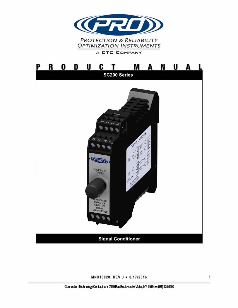
MNX10020, REV J ● 8/17/2016 1 ConnectionTechnologyCenter,Inc. ● 7939RaeBoulevard ● Victor,NY14564 ● (585)924-5900 SC200 Series Signal Conditioner
Transcript of MNX10020, REV J - ctconline.com REV H.pdf · MNX10020, REV J 8/17/2016 3 Connection Technology...
MNX10020, REV J ● 8 /17 /2016 1
Connection Technology Center, Inc. ● 7939 Rae Boulevard ● Victor, NY 14564 ● (585) 924-5900
SC200 Series
Signal Conditioner
MNX10020, REV J ● 8 /17 /2016 2
Connection Technology Center, Inc. ● 7939 Rae Boulevard ● Victor, NY 14564 ● (585) 924-5900
C O N T E N T S
SECTION 1: OVERVIEW ............................................................................................................. 4
Introduction ..................................................................................................................................... 4
Description ...................................................................................................................................... 4
Ordering Information ....................................................................................................................... 4
Specifications ................................................................................................................................... 5
Environmental ....................................................................................................................................................... 5
Electrical ................................................................................................................................................................ 5
Physical ................................................................................................................................................................. 5
SECTION 2: INSTALLATION ....................................................................................................... 7
Mounting Instructions ...................................................................................................................... 7
Mounting .............................................................................................................................................................. 7
Signal Conditioner Configuration and DIP Switch Settings ................................................................................... 7
Electrical Connections .................................................................................................................... 11
SECTION 3: OPERATION ......................................................................................................... 13
Calibration ..................................................................................................................................... 13
Indicators ....................................................................................................................................... 13
Portable Data Collector Interfacing ................................................................................................ 13
SECTION 4: TROUBLESHOOTING ............................................................................................ 14
Common Problems ......................................................................................................................... 14
SECTION 5: MAINTENANCE .................................................................................................... 15
General .......................................................................................................................................... 15
Warranty ....................................................................................................................................... 15

MNX10020, REV J ● 8 /17 /2016 3
Connection Technology Center, Inc. ● 7939 Rae Boulevard ● Victor, NY 14564 ● (585) 924-5900
F I G U R E S
Figure 1. SC200 Series Selection Guide ......................................................................................................... 4
Figure 2. SC200 Series Overall Dimensions ................................................................................................... 6
Figure 3. DIN Rail Release ............................................................................................................................. 7
Figure 4. Terminal Block Removal ................................................................................................................. 7
Figure 5. Opening of Housing ........................................................................................................................ 8
Figure 6. Close up of Dip Switch Settings ...................................................................................................... 8
Figure 7. Examples of Dip Switch Configurations ......................................................................................... 9
Figure 8. Signal Conditioner Electrical Wiring Diagram .............................................................................. 12
Figure 9. Conditioner Front Panel Dynamic Signal Output ......................................................................... 12
Figure 10. Portable Data Collector Interface .............................................................................................. 13

MNX10020, REV J ● 8 /17 /2016 4
Connection Technology Center, Inc. ● 7939 Rae Boulevard ● Victor, NY 14564 ● (585) 924-5900
S E C T I O N 1 : O V E R V I E W
Introduction This document contains information on the operation, installation and maintenance of the SC200 Series Signal Conditioner. The Signal Conditioner is a device that converts a sensor input into a powered 4-20mA, 0-5V DC, or a 0-10V DC output and provides a buffered dynamic output of the vibration waveform. The Signal Conditioner can take an input from an Accelerometer, Velocity Transducer or AC signal from Proximity Probe Driver. As an added feature, sensor power can be turned off, to accept inputs from a sensor that is already powered. The Signal Conditioner can be set to output the powered 4-20mA signal (and an additional analog voltage output) in proportion to Acceleration, Velocity or Displacement regardless of the type of input transducer.
Description The Signal Conditioner is a DIN rail mountable component used in continuous machinery monitoring applications. It provides signal conditioning, signal conversion and re-transmission. The Signal Conditioners are traditionally mounted inside a sealed enclosure. All settings are configured using simple DIP switches internal to the Signal Conditioner’s case.
Ordering Information The SC200 Series Signal Conditioner has a wide variety of different configurations for the many different applications it can be used for. Below is the standard selection guide to use to determine the correct configuration.
Figure 1. SC200 Series Selection Guide

MNX10020, REV J ● 8 /17 /2016 5
Connection Technology Center, Inc. ● 7939 Rae Boulevard ● Victor, NY 14564 ● (585) 924-5900
Specifications
Environmental
Operating Temperature Range: -40°F(-40°C) to 158°F(70°C) Humidity Range: 0-95% Relative, Non-Condensing
Electrical 4 Wire System, Powered 4-20 mA Output Signals for Vibration and Temperature
(0-1.2V Input) Selectable 0-5 or 0-10 VDC Output Signal for Vibration 24 VDC, 4 mA DC Sensor Excitation (IEPE) LED Indicators for Power, Disconnected Sensor and DIP Switch Setting Errors Selectable input switches for RMS 0 – Pk, Pk – Pk Input selectable between Acceleration, Velocity, or Displacement 2 Hz and 20 kHz Analog Filters +3dB on Filter Range 8 High Pass Digital Filters ranging from 5 Hz to 1000 Hz 10 Low Pass Digital Filters ranging from 50 Hz to 15 kHz Outputs scalable for Metric and English Output selectable between Acceleration, Velocity, or Displacement Full Scale Range Limits:
o IPS…..0.5 – 50 o Mm/s..10 – 200 o G’s…..0.5 – 100 o Mils….0.5 – 200
Physical 35 mm DIN Rail Mountable Removable individually keyed terminal blocks facilitate easier wiring & proper
terminal block placement into corresponding signal conditioner slots

MNX10020, REV J ● 8 /17 /2016 6
Connection Technology Center, Inc. ● 7939 Rae Boulevard ● Victor, NY 14564 ● (585) 924-5900
Overall Dimensions:
Figure 2. SC200 Series Overall Dimensions

MNX10020, REV J ● 8 /17 /2016 7
Connection Technology Center, Inc. ● 7939 Rae Boulevard ● Victor, NY 14564 ● (585) 924-5900
S E C T I O N 2 : I N S T A L L A T I O N
Mounting Instructions
Mounting The Signal Conditioner is designed to be mounted on 35 mm DIN rail. The mounting clip is spring loaded to facilitate simple permanent locating. To remove the Signal Conditioner, it is recommended that a small flat-head screw-driver be used as a lever on the spring loaded mount clip. With the clip disengaged, simply slide the Signal Conditioner off of the mounting rail.
Figure 3. DIN Rail Release
To make removal easier the terminal blocks can be removed with a small flat head screw driver without the need to disconnect wiring. The terminal blocks are keyed individually to avoid terminal block miss placement.
Figure 4. Terminal Block Removal
Signal Conditioner Configuration and DIP Switch Settings The transmitter is configured using 24 internal DIP switches. To open the Signal Conditioner case, depress the tabs holding the housing to the top cover and gently slide the circuit board out of the

MNX10020, REV J ● 8 /17 /2016 8
Connection Technology Center, Inc. ● 7939 Rae Boulevard ● Victor, NY 14564 ● (585) 924-5900
housing. The circuit board can be removed with the plugs and wiring still attached. Note: CTC does not advise in removing the housing while the unit is powered.
Figure 5. Opening of Housing
There are 3 sets of DIP switches, each labeled 1-8. SW 1 contains switches numbered 1 – 8 in Table 1. SW 2 contains the switches 1-8 from Table 1. SW 3 contains the switches numbered 1-8 in Table 1. (See figure 5)
Figure 6. Close up of Dip Switch Settings
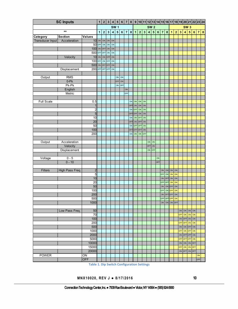
To configure the transmitter, use Table 1 and set the appropriate combination of DIP Switches.

MNX10020, REV J ● 8 /17 /2016 9
Connection Technology Center, Inc. ● 7939 Rae Boulevard ● Victor, NY 14564 ● (585) 924-5900
Figure 7. Examples of Dip Switch Configurations
The dip switch settings are read only once, during start up. Therefore, any changes in the DIP switches settings will have no effect on system operation until the signal conditioner is disconnected from power, then powered on. Note: CTC does not advise in adjusting any dip switches while the unit is powered. The Signal Conditioner’s electronics are limited to 10V swings and like all electronic devices, it is subject to noise. Therefore, any setting which would require more that 10V or less than several mV cannot be used. Contact an Applications Engineer for further information regarding troubleshooting the transmitter’s settings. Note: The 15kHz LOW PASS FILTER can ONLY be used with a 1000 Hz HIGH PASS FILTER. Note: For Displacement Input, low pass filter limit is 2000 Hz
- 100 mV/g Acceleration Input- Output Level Based on RMS Level of Input Signal- Velocity Output with Full Scale of 2 IPS @ RMS- 0 to 5 VDC Analog Output- Filter Bandwidth from 5 to 500 Hz- Power on (supplied)
1 2 3 4 5 6 7 8
→ ON OFF ON ON ON ON ON ON
→ OFF ON ON OFF ON ON OFF ON
→ ON ON ON ON OFF ON ON ON
SW 1SW 2SW 3
Example Configuration 1: (SC207-100A-002-IR-005-500-05)
------
1 2 3 4 5 6 7 8
→ OFF ON OFF ON OFF ON ON OFF
→ OFF ON ON ON ON OFF ON ON
→ OFF ON OFF OFF ON ON OFF ONSW 2SW 3
100 mV/IPS Acceleration InputOutput Level Based on 0-Pk Level of Input SignalAcceleration Output with Full Scale of 5 G's0 to 10 VDC Analog OutputFilter Bandwidth from 50 to 200 HzPower off (not supplied)
Example Configuration 2: (SC207-100V-005-GP-050-200-10-N)
SW 1
MNX10020, REV J ● 8 /17 /2016 10
Connection Technology Center, Inc. ● 7939 Rae Boulevard ● Victor, NY 14564 ● (585) 924-5900
Table 1. Dip Switch Configuration Settings
1 2 3 4 5 6 7 8 9 10 11 12 13 14 15 16 17 18 19 20 21 22 23 24
1 2 3 4 5 6 7 8 1 2 3 4 5 6 7 8 1 2 3 4 5 6 7 8
Category Section ValuesTransducer Input Acceleration 10 ON ON ON ON
50 OFF ON ON ON
100 ON OFF ON ON
500 OFF OFF ON ON
Velocity 10 ON ON OFF ON
100 OFF ON OFF ON
500 ON OFF OFF ON
Displacement 200 OFF OFF OFF ON
Output RMS ON ON
0-Pk OFF ON
Pk-Pk ON OFF
English ON
Metric OFF
Full Scale 0.5 ON ON ON ON
1 OFF ON ON ON
2 ON OFF ON ON
5 OFF OFF ON ON
10 ON ON OFF ON
20 OFF ON OFF ON
50 ON OFF OFF ON
100 OFF OFF OFF ON
200 ON ON ON OFF
Output Acceleration ON ON
Velocity OFF ON
Displacement ON OFF
Voltage 0 - 5 ON
0 - 10 OFF
Filters High Pass Freq. 2 ON ON ON ON
5 OFF ON ON ON
10 ON OFF ON ON
20 OFF OFF ON ON
50 ON ON OFF ON
100 OFF ON OFF ON
200 ON OFF OFF ON
500 OFF OFF OFF ON
1000 ON ON ON OFF
Low Pass Freq. 50 ON ON ON ON
70 OFF ON ON ON
100 ON OFF ON ON
200 OFF OFF ON ON
500 ON ON OFF ON
1000 OFF ON OFF ON
2000 ON OFF OFF ON
5000 OFF OFF OFF ON
10000 ON ON ON OFF
15000 OFF ON ON OFF
20000 ON OFF ON OFF
POWER ON ON
OFF OFF
SC InputsSW 1 SW 2 SW 3
**
MNX10020, REV J ● 8 /17 /2016 11
Connection Technology Center, Inc. ● 7939 Rae Boulevard ● Victor, NY 14564 ● (585) 924-5900
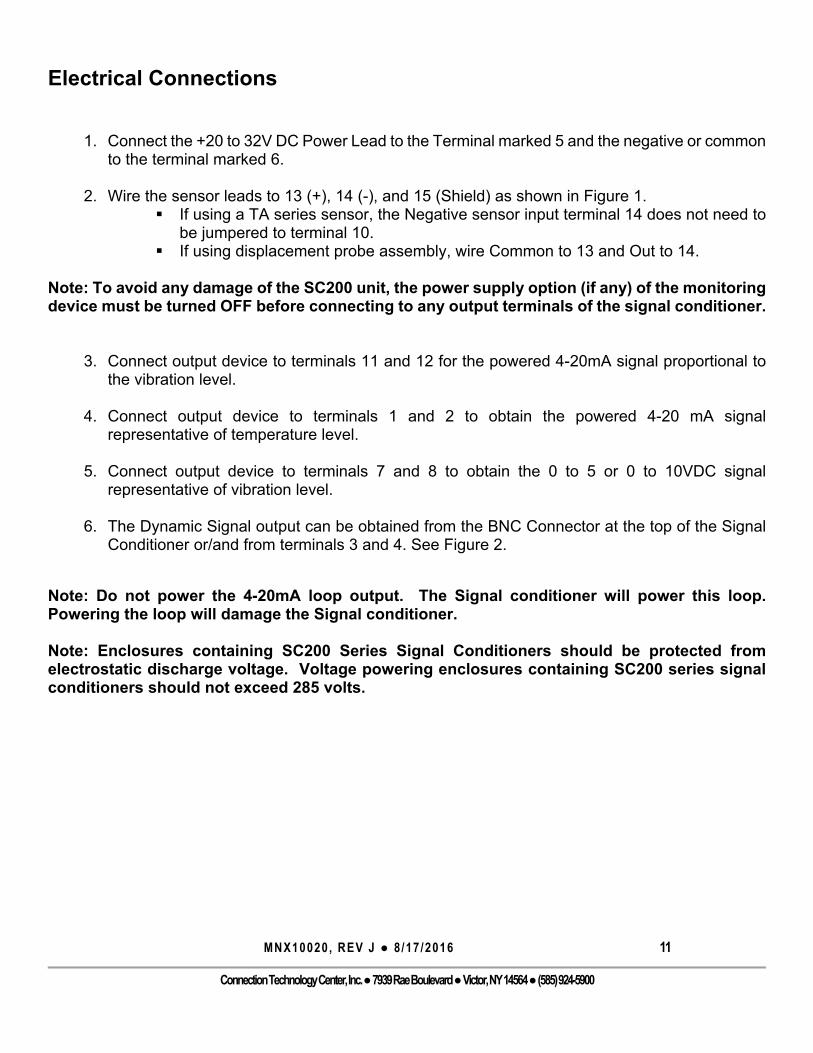
Electrical Connections
1. Connect the +20 to 32V DC Power Lead to the Terminal marked 5 and the negative or common to the terminal marked 6.
2. Wire the sensor leads to 13 (+), 14 (-), and 15 (Shield) as shown in Figure 1.
If using a TA series sensor, the Negative sensor input terminal 14 does not need to be jumpered to terminal 10.
If using displacement probe assembly, wire Common to 13 and Out to 14.
Note: To avoid any damage of the SC200 unit, the power supply option (if any) of the monitoring device must be turned OFF before connecting to any output terminals of the signal conditioner.
3. Connect output device to terminals 11 and 12 for the powered 4-20mA signal proportional to
the vibration level. 4. Connect output device to terminals 1 and 2 to obtain the powered 4-20 mA signal
representative of temperature level. 5. Connect output device to terminals 7 and 8 to obtain the 0 to 5 or 0 to 10VDC signal
representative of vibration level. 6. The Dynamic Signal output can be obtained from the BNC Connector at the top of the Signal
Conditioner or/and from terminals 3 and 4. See Figure 2.
Note: Do not power the 4-20mA loop output. The Signal conditioner will power this loop. Powering the loop will damage the Signal conditioner. Note: Enclosures containing SC200 Series Signal Conditioners should be protected from electrostatic discharge voltage. Voltage powering enclosures containing SC200 series signal conditioners should not exceed 285 volts.

MNX10020, REV J ● 8 /17 /2016 12
Connection Technology Center, Inc. ● 7939 Rae Boulevard ● Victor, NY 14564 ● (585) 924-5900
Figure 8. Signal Conditioner Electrical Wiring Diagram
Figure 9. Conditioner Front Panel Dynamic Signal Output
Pin ColorA RedB BlackC White
4 - 20 mA Output
168
+20 - 32 VDC
Common
Ain +( D - co mmo n)
Ain -( D + OU T )
Ain GND
Sensor Signal Input
Vout -
Temperature Input
Powerin +
Powerin -
0-5 or 0-10 VDC Output
Vout +
Aout -
9
10
11
12
Tempin +( 0 t o 1.2 V D C )
Tempin -
Aout +
6
7
13
14
15
Tempout -
Sensorout +
5
1
2
3
4
CTC TA Series Sensores are a 3 Wire System
Sensorout -
4 - 20 mA Output
Dynamic Signal Output
Polarity
(+) Temperature Voltage(-) Common(+) Signal/Power
Tempout +
Dynamic
Signal
Output
(BNC)
1 ‐ 4
5 ‐ 8
9 ‐ 12
13 ‐ 16
Powered Output
Powered Output

MNX10020, REV J ● 8 /17 /2016 13
Connection Technology Center, Inc. ● 7939 Rae Boulevard ● Victor, NY 14564 ● (585) 924-5900
S E C T I O N 3 : O P E R A T I O N
Once all wires are connected, apply power to begin operating the Signal Conditioner. Make sure the status light is indicating normal mode (Constant ON).
Calibration The Signal Conditioner is calibrated internally during power up. The digital calibration eliminates the need for any adjustments to the Analog Output.
Indicators The LED on the front of the Signal Conditioner will indicate the status of the Signal Conditioner. A constant bright LED indicates normal operating condition, and a Flashing LED indicates an error has occurred.
STATE 1 – “Normal” Mode Operation • LED is a “Solid” ON ( ) STATE 2 – Error Detected • LED is flashing ON and OFF in 0.5 second Intervals. ( ) • Errors can be due to
o Input Sensor bias voltage < 5 V. Sensor is considered shorted. o Input Sensor bias voltage > 15 V. Sensor is considered
unconnected/missing. o Invalid configuration of switch settings.
Portable Data Collector Interfacing In order to collect waveform data from the BNC jack on the Signal Conditioner using a portable data collector that supplies constant current power, the data collector must be set so that power to the sensor is turned off. Failure to do so may result in a damaged or non-functional transmitter.
Figure 10. Portable Data Collector Interface
BNC Jack for Portable
Data Collecting

MNX10020, REV J ● 8 /17 /2016 14
Connection Technology Center, Inc. ● 7939 Rae Boulevard ● Victor, NY 14564 ● (585) 924-5900
S E C T I O N 4 : T R O U B L E S H O O T I N G
Common Problems
Problem Description
Recommended Actions
4 - 20 mA or 0 - 5,10V Output is non-functional.
Check status LED; ensure Signal Conditioner is in Normal mode. Check DIP switch settings for validity and make sure sensor is properly wired. Refer to wiring diagram in Figure 3.
Check for power to sensor.
Check to make sure the system is not powering the loop. The SC is powering the loop.
No waveform data from BNC jack.
Check status LED; ensure Signal Conditioner is in Normal mode. Check DIP switch settings for validity and make sure sensor is properly wired. Refer to wiring diagram in Figure 3.
4 - 20mA or 0 - 5,10V output is lower than expected.
Check filter settings. Make sure low pass and high pass filters have been set to a range capable of capturing the expected frequencies. Check and make sure you’re on the proper scaling settings. (Pk-Pk, RMS, …)
Table 2. Common Troubleshooting
Note: For specific problem resolution, please call an Applications Engineer at 1-800-999-5290.
MNX10020, REV J ● 8 /17 /2016 15
Connection Technology Center, Inc. ● 7939 Rae Boulevard ● Victor, NY 14564 ● (585) 924-5900
S E C T I O N 5 : M A I N T E N A N C E
General There are no customer replaceable parts. The device has been designed to self-calibrate and monitor its own operational status. It should provide trouble free continuous service under normal operating conditions.
Warranty If any PRO product should ever fail, we will repair or replace it at no charge as long as the product was not subject to misuse, natural disasters, improper installation or modification which caused the defect.