MN225025EN QD5 Quik-Drive Tap-Changer Reversing … · QD5 Quik-Drive tap-changer reversing neutral...
12
QD5 Quik-Drive tap-changer reversing neutral stationary contact asssembly kit 5791646A26 installation instructions COOPER POWER SERIES Voltage Regulators MN225025EN Effective March 2016 Supersedes S225-50-48 November 2008
-
Upload
nguyenkhuong -
Category
Documents
-
view
241 -
download
4
Transcript of MN225025EN QD5 Quik-Drive Tap-Changer Reversing … · QD5 Quik-Drive tap-changer reversing neutral...
QD5 Quik-Drive tap-changer reversing neutral stationary contact asssembly kit 5791646A26 installation instructions
COOPER POWERSERIES
Voltage Regulators MN225025EN
Effective March 2016Supersedes S225-50-48 November 2008
DISCLAIMER OF WARRANTIES AND LIMITATION OF LIABILITY
The information, recommendations, descriptions and safety notations in this document are based on Eaton Corporation’s (“Eaton”) experience and judgment and may not cover all contingencies. If further information is required, an Eaton sales office should be consulted. Sale of the product shown in this literature is subject to the terms and conditions outlined in appropriate Eaton selling policies or other contractual agreement between Eaton and the purchaser.
THERE ARE NO UNDERSTANDINGS, AGREEMENTS, WARRANTIES, EXPRESSED OR IMPLIED, INCLUDING WARRANTIES OF FITNESS FOR A PARTICULAR PURPOSE OR MERCHANTABILITY, OTHER THAN THOSE SPECIFICALLY SET OUT IN ANY EXISTING CONTRACT BETWEEN THE PARTIES. ANY SUCH CONTRACT STATES THE ENTIRE OBLIGATION OF EATON. THE CONTENTS OF THIS DOCUMENT SHALL NOT BECOME PART OF OR MODIFY ANY CONTRACT BETWEEN THE PARTIES.
In no event will Eaton be responsible to the purchaser or user in contract, in tort (including negligence), strict liability or other-wise for any special, indirect, incidental or consequential damage or loss whatsoever, including but not limited to damage or loss of use of equipment, plant or power system, cost of capital, loss of power, additional expenses in the use of existing power facilities, or claims against the purchaser or user by its customers resulting from the use of the information, recom-mendations and descriptions contained herein. The information contained in this manual is subject to change without notice.
ii QD5 REVERSING NEUTRAL STATIONARY CONTACT ASSEMBLY KIT INSTRUCTIONS MN225025EN March 2016
Contents
SAFETY INFORMATIONSafety information . . . . . . . . . . . . . . . . . . . . . . . . . . . . . . . . . . . . . . . . . . . . . . . . . . . . . . . . . . . . . . . . . . . . . . . . . . . . . iv
PRODUCT INFORMATIONIntroduction . . . . . . . . . . . . . . . . . . . . . . . . . . . . . . . . . . . . . . . . . . . . . . . . . . . . . . . . . . . . . . . . . . . . . . . . . . . . . . . . . . .1
Parts supplies . . . . . . . . . . . . . . . . . . . . . . . . . . . . . . . . . . . . . . . . . . . . . . . . . . . . . . . . . . . . . . . . . . . . . . . . . . . . . . . . . .1
Tools required . . . . . . . . . . . . . . . . . . . . . . . . . . . . . . . . . . . . . . . . . . . . . . . . . . . . . . . . . . . . . . . . . . . . . . . . . . . . . . . . . .1
Acceptance and initial inspection . . . . . . . . . . . . . . . . . . . . . . . . . . . . . . . . . . . . . . . . . . . . . . . . . . . . . . . . . . . . . . . . . . .1
Handling and storage . . . . . . . . . . . . . . . . . . . . . . . . . . . . . . . . . . . . . . . . . . . . . . . . . . . . . . . . . . . . . . . . . . . . . . . . . . . .1
Standards . . . . . . . . . . . . . . . . . . . . . . . . . . . . . . . . . . . . . . . . . . . . . . . . . . . . . . . . . . . . . . . . . . . . . . . . . . . . . . . . . . . . .1
INSTALLATION PROCEDURERemoving existing contact assembly. . . . . . . . . . . . . . . . . . . . . . . . . . . . . . . . . . . . . . . . . . . . . . . . . . . . . . . . . . . . . . . .2
Installing replacement contact and reassembly. . . . . . . . . . . . . . . . . . . . . . . . . . . . . . . . . . . . . . . . . . . . . . . . . . . . . . . .4
Placing tap-changer into neutral . . . . . . . . . . . . . . . . . . . . . . . . . . . . . . . . . . . . . . . . . . . . . . . . . . . . . . . . . . . . . . . . . . . .7
iiiQD5 REVERSING NEUTRAL STATIONARY CONTACT ASSEMBLY KIT INSTRUCTIONS MN225025EN March 2016

The instructions in this manual are not intended as a substitute for proper training or adequate experience in the safe operation of the equipment described. Only competent technicians who are familiar with this equipment should install, operate, and service it.
A competent technician has these qualifications:
• Is thoroughly familiar with these instructions.
• Is trained in industry-accepted high and low-voltage safe operating practices and procedures.
• Is trained and authorized to energize, de-energize, clear, and ground power distribution equipment.
• Is trained in the care and use of protective equipment such as arc flash clothing, safety glasses, face shield, hard hat, rubber gloves, clampstick, hotstick, etc.
Following is important safety information. For safe installa-tion and operation of this equipment, be sure to read and understand all cautions and warnings.
Safety instructionsFollowing are general caution and warning statements that apply to this equipment. Additional statements, related to specific tasks and procedures, are located throughout the manual.
Safety for life!
SAFETYFOR LIFE
!SAFETYFOR LIFE
Eaton meets or exceeds all applicable industry standards relating to product safety in its Cooper Power™ series products. We actively promote safe practices in the use and maintenance of our products through our service literature, instructional training programs, and the continuous efforts of all Eaton employees involved in product design, manufacture, marketing, and service.
We strongly urge that you always follow all locally approved safety procedures and safety instructions when working around high voltage lines and equipment, and support our “Safety For Life” mission.
Safety information
DANGERHazardous voltage. Contact with hazardous voltage will cause death or severe personal injury. Follow all locally approved safety procedures when working around high- and low-voltage lines and equipment. G103.3
WARNING Before installing, operating, maintaining, or testing this equipment, carefully read and understand the contents of this manual. Improper operation, handling or maintenance can result in death, severe personal injury, and equipment damage. G101.0
WARNING This equipment is not intended to protect human life. Follow all locally approved procedures and safety practices when installing or operating this equipment. Failure to comply can result in death, severe personal injury and equipment damage. G102.1
WARNING Power distribution and transmission equipment must be properly selected for the intended application. It must be installed and serviced by competent personnel who have been trained and understand proper safety procedures. These instructions are written for such personnel and are not a substitute for adequate training and experience in safety procedures. Failure to properly select, install or maintain power distribution and transmission equipment can result in death, severe personal injury, and equipment damage. G122.3
This manual may contain four types of hazard statements:
DANGER Indicates an imminently hazardous situation which, if not avoided, will result in death or serious injury.
WARNING Indicates a potentially hazardous situation which, if not avoided, could result in death or serious injury.
CAUTION Indicates a potentially hazardous situation which, if not avoided, may result in minor or moderate injury.
CAUTIONIndicates a potentially hazardous situation which, if not avoided, may result in equipment damage only.
Hazard Statement Definitions
iv QD5 REVERSING NEUTRAL STATIONARY CONTACT ASSEMBLY KIT INSTRUCTIONS MN225025EN March 2016

Product information
IntroductionService Information MN225025EN provides the instructions for replacing Eaton's Cooper Power™ series QD5 Quik-Drive™ tap-changer reversing neutral stationary contact on Eaton's Cooper Power series 32-step voltage regulator. For normal maintenance, the contact is replaced before critical contact erosion has occurred.
Refer to Service Information MN225003EN CL-7 Series Control Installation, Operation, and Maintenance Instructions for information on the CL-6 voltage regulator control. Refer to Service Information MN225016EN CL-6 Series Control Installation, Operation, and Maintenance Instructions for information on the CL-6 voltage regulator control. Refer to Service Information MN225008EN VR-32 Voltage Regulator with Quik-Drive Tap-Changer Installation, Operation, and Maintenance Instructions for information on Eaton's voltage regulator with Quik-Drive tap-changer.
Read this manual first Read and understand the contents of this manual and follow all locally approved procedures and safety practices before installing or operating this equipment. Read and understand the manuals detailing the installation and operation of the regulator and the regulator control used with the regulator.
Additional information
These instructions cannot cover all details or variations in the equipment, procedures, or process described nor provide directions for meeting every possible contingency during installation, operation, or maintenance. For additional information, please contact your Eaton representative.
Acceptance and initial inspection This kit is thoroughly inspected at the factory. It is in good condition when accepted by the carrier for shipment.
Upon receipt of the regulator kit, a thorough inspection should be made for damage, evidence of rough handling, or shortages. Should this initial inspection reveal evidence of rough handling, damage, or shortages, file a claim with the carrier immediately. Also, notify your Eaton representative.
Handling and storage Be careful during handing and storage of the kit to minimize the possibility of damage. If the regulator kit is not to be placed into immediate use, store the kit in a clean, dry location.
Quality standardsISO 9001 Certified Quality Management System
Parts supplied
Item Part Number Description Qty
1 0791646A26 Reversing Neutral Stationary Contact
1
Tools required
• Ratchet Wrench
• 3/8 inch Socket
• 7/16 inch Socket
• 9/16 inch Deep-well Socket
• Torque Wrench, in-lbs
• Small flat-blade Screwdriver or 5/32 inch Allen Wrench
• 8" Long flat-blade Screwdriver
• Loctite® 243™ Threadlocker
Figure 1. Reversing neutral stationary contact.
1QD5 REVERSING NEUTRAL STATIONARY CONTACT ASSEMBLY KIT INSTRUCTIONS MN225025EN March 2016
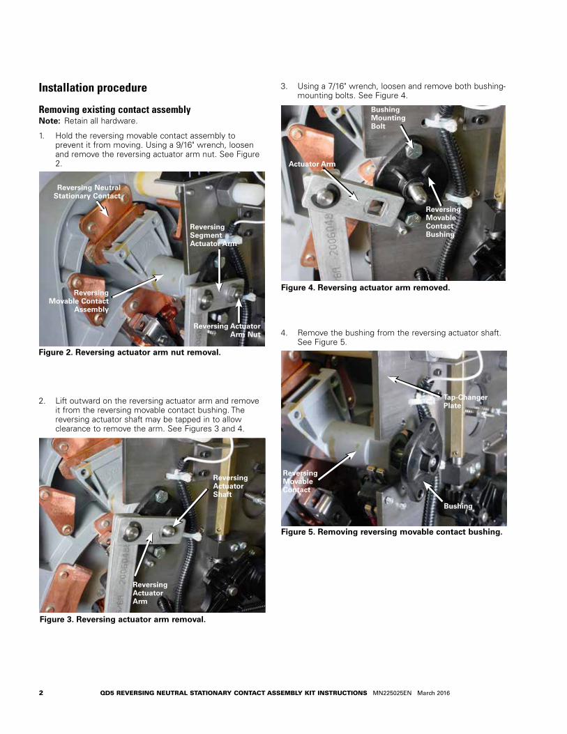
Installation procedure
Removing existing contact assemblyotee:N Retain all hardware.
1. Hold the reversing movable contact assembly to prevent it from moving. Using a 9/16" wrench, loosen and remove the reversing actuator arm nut. See Figure 2.
2. Lift outward on the reversing actuator arm and remove it from the reversing movable contact bushing. The reversing actuator shaft may be tapped in to allow clearance to remove the arm. See Figures 3 and 4.
3. Using a 7/16" wrench, loosen and remove both bushing-mounting bolts. See Figure 4.
4. Remove the bushing from the reversing actuator shaft. See Figure 5.
Figure 3. Reversing actuator arm removal.
Reversing Actuator Shaft
Reversing Actuator Arm
Figure 2. Reversing actuator arm nut removal.
Reversing Neutral Stationary Contact
Reversing Segment Actuator Arm
Reversing Movable Contact
Assembly
Reversing Actuator Arm Nut
Figure 5. Removing reversing movable contact bushing.
Bushing
Reversing Movable Contact
Tap-Changer Plate
Figure 4. Reversing actuator arm removed.
Actuator Arm
Bushing Mounting Bolt
Reversing Movable Contact Bushing
2 QD5 REVERSING NEUTRAL STATIONARY CONTACT ASSEMBLY KIT INSTRUCTIONS MN225025EN March 2016
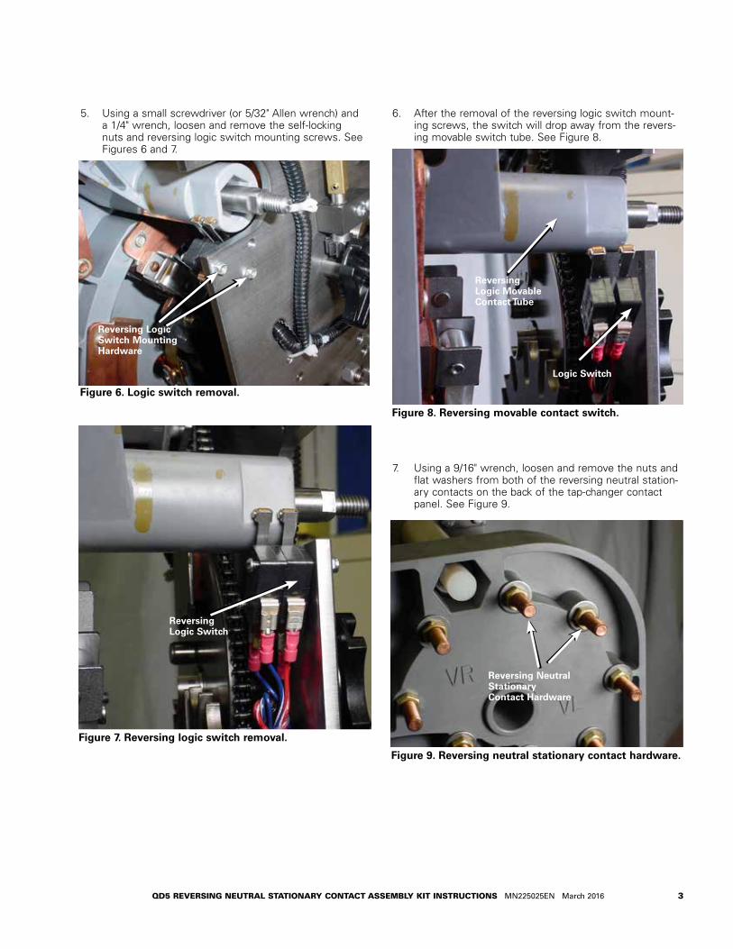
5. Using a small screwdriver (or 5/32" Allen wrench) and a 1/4" wrench, loosen and remove the self-locking nuts and reversing logic switch mounting screws. See Figures 6 and 7.
6. After the removal of the reversing logic switch mount-ing screws, the switch will drop away from the revers-ing movable switch tube. See Figure 8.
7. Using a 9/16" wrench, loosen and remove the nuts and flat washers from both of the reversing neutral station-ary contacts on the back of the tap-changer contact panel. See Figure 9.
Figure 6. Logic switch removal.
Reversing Logic Switch Mounting Hardware
Figure 7. Reversing logic switch removal.
Reversing Logic Switch
Figure 9. Reversing neutral stationary contact hardware.
Reversing Neutral Stationary Contact Hardware
Figure 8. Reversing movable contact switch.
Logic Switch
Reversing Logic Movable Contact Tube
3QD5 REVERSING NEUTRAL STATIONARY CONTACT ASSEMBLY KIT INSTRUCTIONS MN225025EN March 2016
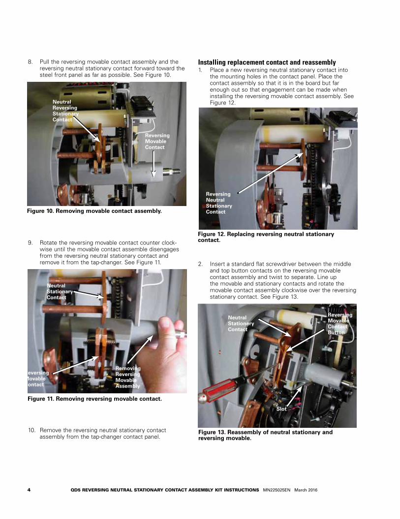
8. Pull the reversing movable contact assembly and the reversing neutral stationary contact forward toward the steel front panel as far as possible. See Figure 10.
9. Rotate the reversing movable contact counter clock-wise until the movable contact assemble disengages from the reversing neutral stationary contact and remove it from the tap-changer. See Figure 11.
10. Remove the reversing neutral stationary contact assembly from the tap-changer contact panel.
Installing replacement contact and reassembly1. Place a new reversing neutral stationary contact into
the mounting holes in the contact panel. Place the contact assembly so that it is in the board but far enough out so that engagement can be made when installing the reversing movable contact assembly. See Figure 12.
2. Insert a standard flat screwdriver between the middle and top button contacts on the reversing movable contact assembly and twist to separate. Line up the movable and stationary contacts and rotate the movable contact assembly clockwise over the reversing stationary contact. See Figure 13.
Figure 10. Removing movable contact assembly.
Reversing Movable Contact
Neutral Reversing Stationary Contact
Figure 11. Removing reversing movable contact.
Neutral Stationary Contact
Removing Reversing Movable Assembly
Reversing Movable Contact
Figure 12. Replacing reversing neutral stationary contact.
Figure 13. Reassembly of neutral stationary and reversing movable.
Reversing Neutral Stationary Contact
Neutral Stationery Contact
Reversing Movable Contact Button
Slot
4 QD5 REVERSING NEUTRAL STATIONARY CONTACT ASSEMBLY KIT INSTRUCTIONS MN225025EN March 2016
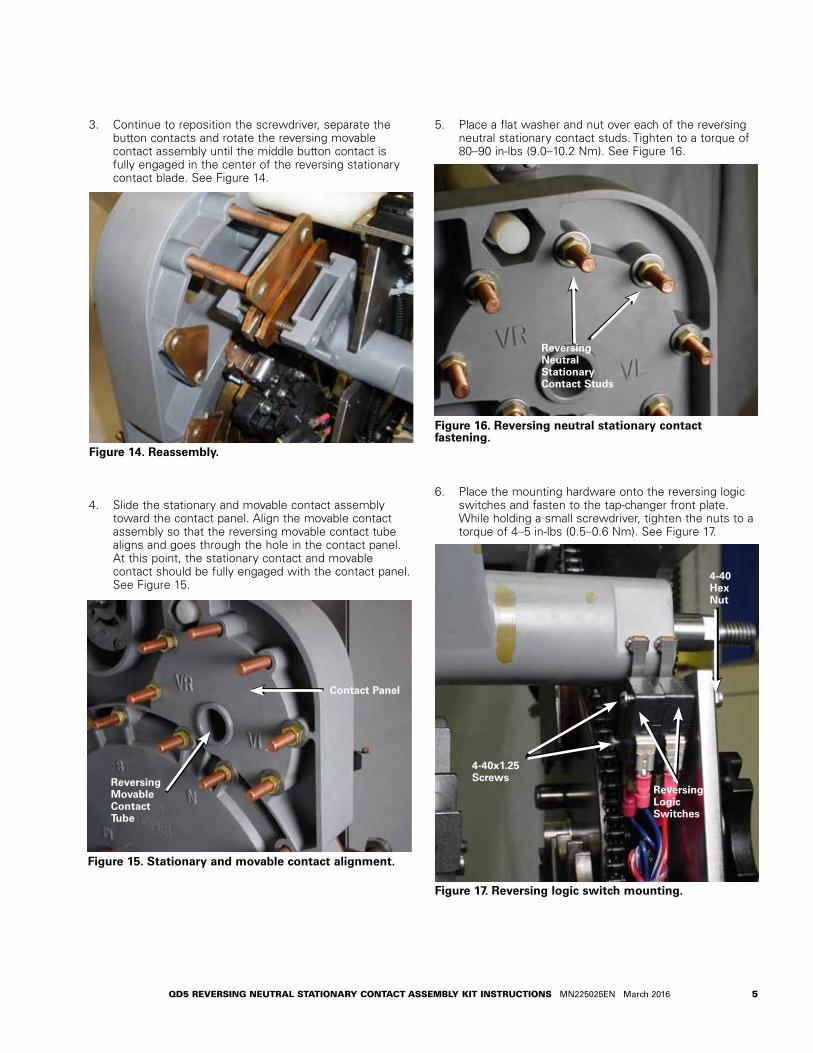
3. Continue to reposition the screwdriver, separate the button contacts and rotate the reversing movable contact assembly until the middle button contact is fully engaged in the center of the reversing stationary contact blade. See Figure 14.
4. Slide the stationary and movable contact assembly toward the contact panel. Align the movable contact assembly so that the reversing movable contact tube aligns and goes through the hole in the contact panel. At this point, the stationary contact and movable contact should be fully engaged with the contact panel. See Figure 15.
5. Place a flat washer and nut over each of the reversing neutral stationary contact studs. Tighten to a torque of 80–90 in-lbs (9.0–10.2 Nm). See Figure 16.
6. Place the mounting hardware onto the reversing logic switches and fasten to the tap-changer front plate. While holding a small screwdriver, tighten the nuts to a torque of 4–5 in-lbs (0.5–0.6 Nm). See Figure 17.
Figure 15. Stationary and movable contact alignment.
Figure 14. Reassembly.
Contact Panel
Reversing Movable Contact Tube
Figure 16. Reversing neutral stationary contact fastening.
Figure 17. Reversing logic switch mounting.
Reversing Neutral Stationary Contact Studs
Reversing Logic Switches
4-40 Hex Nut
4-40x1.25 Screws
5QD5 REVERSING NEUTRAL STATIONARY CONTACT ASSEMBLY KIT INSTRUCTIONS MN225025EN March 2016
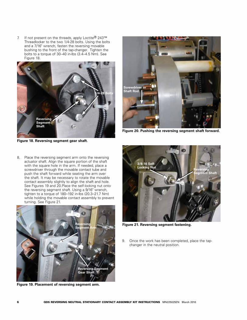
7. If not present on the threads, apply Loctite® 243™ Threadlocker to the two 1/4-28 bolts. Using the bolts and a 7/16" wrench, fasten the reversing movable bushing to the front of the tap-changer. Tighten the bolts to a torque of 30–40 in-lbs (3.4–4.5 Nm). See Figure 18.
8. Place the reversing segment arm onto the reversing actuator shaft. Align the square portion of the shaft with the square hole in the arm. If needed, place a screwdriver through the movable contact tube and push the shaft forward while seating the arm over the shaft. It may be necessary to rotate the movable contact assembly slightly to align the shaft and hole. See Figures 19 and 20.Place the self-locking nut onto the reversing segment shaft. Using a 9/16" wrench, tighten to a torque of 180–192 in-lbs (20.3–21.7 Nm) while holding the movable contact assembly to prevent turning. See Figure 21.
9. Once the work has been completed, place the tap-changer in the neutral position.
Figure 18. Reversing segment gear shaft.
1/4-28 Bolts
Reversing Segment Shaft
Figure 19. Placement of reversing segment arm.
Reversing Segment Arm
Reversing Segment Gear Shaft
Figure 21. Reversing segment fastening.
Reversing Segment Shaft
3/8-16 Self-Locking Nut
Figure 20. Pushing the reversing segment shaft forward.
Screwdriver or Shaft Rod
6 QD5 REVERSING NEUTRAL STATIONARY CONTACT ASSEMBLY KIT INSTRUCTIONS MN225025EN March 2016

Placing tap-changer into neutral1. Place a 3/8" socket and ratchet on the output shaft of
the motor; rotate the motor so that the contacts and other components are aligned in the neutral position
2. Confirm that the regulator is in the neutral position.
A. Main movable contacts are located on the neutral stationary contact, which is located at the 11 o’clock position and under the reversing switch movable contact assembly. See Figure 22.
B. The reversing movable contact is located on the reversing neutral stationary contact. See Figure 23.
C. The pinion cam is pointing to the right over the holding switch actuator. See Figure 24.
Figure 22. Neutral position for main movable contacts.
Neutral Stationary
Main Movable
Figure 23. Neutral position for reversing movable.
Reversing Movable Contact
Reversing Neutral Stationary Contact
Figure 24. Neutral position for position indicator pinion cam and holding switch.
Pinion Cam
Holding Switch Actuator
7QD5 REVERSING NEUTRAL STATIONARY CONTACT ASSEMBLY KIT INSTRUCTIONS MN225025EN March 2016

Eaton1000 Eaton BoulevardCleveland, OH 44122United StatesEaton.com
Eaton’s Cooper Power Systems Division2300 Badger DriveWaukesha, WI 53188United StatesEaton.com/cooperpowerseries
© 2016 EatonAll Rights ReservedPrinted in USAPublication No. MN225025ENMarch 2016
Eaton is a registered trademark.
All trademarks are property of their respective owners.
For Eaton's Cooper Power series product information call 1-877-277-4636 or visit: www.eaton.com/cooperpowerseries.
!SAFETYFOR LIFE