MMS Inter-carrier Implementation Guidelines - cdg.org Inter-carrier...MMS Inter-carrier...
27
1 of 27 GSMNA-CDG MMS Joint Project MMS Inter-carrier Implementation Guideline August17, 2006; Rev 0.0
Transcript of MMS Inter-carrier Implementation Guidelines - cdg.org Inter-carrier...MMS Inter-carrier...

1 of 27
GSMNA-CDG MMS Joint Project
MMS Inter-carrier Implementation Guideline August17, 2006; Rev 0.0

2 of 27
"This Document has been submitted for the sole purpose of promoting discussion within the CDMA Development Group (the “CDG”) and is not binding upon the CDG nor any of its members. Each CDG member acknowledges that CDG does not review the disclosures or contributions of any CDG member nor does CDG verify the status of the ownership of any of the intellectual property rights associated with any such disclosures or contributions. Accordingly, each CDG member should consider all disclosures and contributions as being made solely on an as-is basis. If any CDG member makes any use of any disclosure or contribution, then such use is at such CDG member's sole risk. Each CDG member agrees that CDG shall not be liable to any person or entity (including any CDG member) arising out of any use of any disclosure or contribution including any liability arising out of infringement of intellectual property rights. "

3 of 27
Revision History
Revision Sections impacted Comment Date
R0.0 - Draft, presented to GSMNA &
CDG for their review. 2006/08/17

4 of 27
Contents
1 Introduction...................................................................................................6
1.1 Scope.................................................................................................................6
1.2 Application..........................................................................................................6
2 References.....................................................................................................6
3 Definitions, Acronyms and Abbreviations..................................................7
3.1 Definitions ..........................................................................................................7
3.2 Acronyms and Abbreviations ..............................................................................8
4 General Architecture ....................................................................................9
4.1 Multi-media Transport.......................................................................................10
4.2 Address Resolution and Routing Services........................................................10
4.3 Considerations .................................................................................................11
5 General Requirements................................................................................11
5.1 MM4 Transport .................................................................................................11 5.1.1 MM Transport between Operators..............................................................11 5.1.2 Dedicated Exchange Backbone Connection ..............................................14 5.1.3 Bilateral Direct Connection.........................................................................16
5.2 Recipient address (E.164 Number) Resolution .................................................17 5.2.1 Scope and Assumptions Pertaining to ENUM Functionality .......................17
5.2.1.1 Not in Scope ..................................................................................................... 18 5.2.2 ENUM Recommendations..........................................................................19
5.2.2.1 Options for the Domain Portion of URIs Returned in NAPTR Resource Records 20 5.2.2.2 Failure Scenarios .............................................................................................. 20
5.3 MMSC Address Resolution Using DNS ............................................................20 5.3.1 Local Table Lookup....................................................................................21 5.3.2 DNS Resolution .........................................................................................21
5.4 Vocoders, Encoding and Related Transcoding .................................................22
5.5 Billing ...............................................................................................................22
5.6 Recommendations ...........................................................................................22
6 Service Behavior.........................................................................................23
6.1 Network Service Level Agreement (Network SLA)............................................24
6.2 MMS Interworking Provider Service Level Agreement ......................................25

5 of 27
Index of Figures Figure 1. Inter-operator MMS Architecture ....................................................................10 Figure 2 - MMS Broker/Hubbing Service Model Architecture.........................................12 Figure 3 - MM4 Network Interconnection Model ............................................................13 Figure 4 - MMSIP Service Model...................................................................................14 Figure 5 - Dedicated Exchange Backbone Connection..................................................15 Figure 6 - Private/Dedicated Line Direction Connect Model...........................................16 Figure 7 - VPN Direct Connection Model.......................................................................16 Figure 8 - ENUM Signaling Flow ...................................................................................18 Figure 9 - MMS Delivery Success Rate.........................................................................26 Figure 10 - MMS Delivery Latency ................................................................................27

6 of 27
1 Introduction The CDMA Development Group (CDG) and Global System for Mobile communication North America (GSMNA) members met jointly to identify key elements needed to ensure that Multimedia Messaging Service deployments are fully interoperable between operators belonging to these 2 groups. Through consensus, the participating operators and vendors have developed the following guideline; covering multimedia message routing and MMS Relay network connectivity; vocoders, encoding and related transcoding; MM billing/charging; and Service Level Agreement. This joint work group effort was formed ultimately to: Facilitate MMS service deployments based on 3GPP Release 5 [R01], 3GPP2 Release 0 [R02, R04], and the corresponding subset of OMA IOP MMS1.3 [R05], specifically, with respect to the requirements needed to support: 1. Multimedia Message routing, 2. MMS Relay network connectivity, 3. Vocoders, encoders and related transcoding, and 4. MM billing/charging
1.1 Scope The purpose of this guidance document is to provide additional focus on Multi-Media Messaging System (MMS) inter-operator interoperability. Specifically, this document identifies and profiles existing standard interfaces, connectivity options, and expected operational characteristics between CDMA and GSM operators which are necessary to implement MMS interoperability. The scope for this document includes the identification, considerations and/or recommendations of the following:
• Transport options for CDMA and GSMNA operators • MMSC (MM4 interface) IP address resolution • Vocoders, encoding and related transcoding • Method of inter-carrier billing • Service behavior and SLA • Performance reporting
1.2 Application This document is intended to serve as a basis for establishing common operation across operators.
2 References

7 of 27
[R01] 3GPP TS 23.140 V5.11.0 (2004-06) Multimedia Messaging Services (MMS); Functional Description; Stage 2 (Release 5) http://www.3gpp.org/ftp/Specs/archive/23_series/23.140/23140-5b0.zip [R02] 3GPP2 X.S0016-000-B, 3GPP2 Multimedia Messaging System, MMS Specification Overview , http://www.3gpp2.org/Public_html/specs/nospec.cfm [R03] Void [R04] 3GPP2 X.S0016-340-0 MMS MM4 Stage 3 Inter-carrier Interworking”; URL: http://www.3gpp2.org/Public_html/specs/nospec.cfm [R05] OMA, OMA-IOP-MMS-ETS-V1_3: “Enabler Test Specification for MMS 1.3”; URL: TDB [R06] IETF, RFC 3761: “The E.164 to Uniform Resource Identifiers (URI) Dynamic Delegation Discovery System (DDDS) Application (ENUM)” http://www.ietf.org/rfc/rfc3761.txt [R07] OMA, OMA-MMS- CONF-V1_2-A: ”MMS Conformance Document”; URL: http://www.openmobilealliance.org/ftp/Public_documents/MWG/MMS/permanent_documents/OMA-MMS-CONF-V1_2-20050301-A.zip [R08] 3GPP2 X.S0016-200-0 “Multimedia Messaging Service; Stage 2 Functional Description”; URL http://www.3gpp2.org/Public_html/specs/nospec.cfm [R09] IETF, RFC 1771: “A Border Gateway Protocol 4 (BGP-4)”, http://www.ietf.org/rfc/rfc1771.txt [R10] CTIA: “Inter-carrier MMS Messaging Guidelines” Revision 1.0, October 21, 2004; URL: http://files.ctia.org/pdf/CTIAInter-carrierMMSGuidelines.pdf [R11] IETF, RFC 4355: “IANA Registration for ENUMservices email, fax, mms ems and sms”, http://www.ietf.org/rfc/rfc4355.txt [R12] IETF, Draft: “MMS URI Schemes”, http://ietfreport.isoc.org/idref/draft-wugofski-mms-uri-scheme [R13] 3GPP2 X.S0016-200-0_V2.0 “Multimedia Messaging Service; Stage 2 Functional Description”; URL: http://www.3gpp2.org/Public_html/specs/nospec.cfm [R14] 3GPP2 X.S0016-200-A_V1.0 “Multimedia Messaging Service; Stage 2 Functional Description”; URL: http://www.3gpp2.org/Public_html/specs/nospec.cfm
3 Definitions, Acronyms and Abbreviations
3.1 Definitions ENUM ENUM is a protocol developed by the Internet Engineering Task Force (IETF) where by the Domain Name System (DNS) can be used for identifying available services associated with an E.164 number. The term Operator ENUM refers to ENUM functionality implemented by Operators on a private basis with controlled access. This differs from the original conception of ENUM (a.k.a. Public ENUM or End User ENUM,,as defined in [R06]), in which users publicly post records on an opt-in basis. Operator ENUM complies with [R06] except that, unlike public ENUM, it does not reside under e164.arpa.

8 of 27
Central Peering Point Central peering point refers to a common data exchange site where exchange service providers can be physically interconnected to each other (e.g., using Ethernet, Fiber, and ATM). The central peering point is the location that facilitates the exchange of traffic with different interfaces between different exchange service providers. A service provider other than the exchange service providers should manage the central peering point. When used to interconnect exchange service providers, the central peering point should meet all operator requirements in terms of security and SLA guarantees. MMS Delivery Success Rate MMS Delivery Success Rate is defined as the ratio between the total number of messages sent against the total number of messages received by a particular party in the message delivery chain such as the MMSC or the MMSIP.
3.2 Acronyms and Abbreviations
3GPP Third Generation Partnership Project
3GPP2 Third Generation Partner Project 2
ATM Asynchronous Transfer Mode
BGP Border Gateway Protocol
CDG CDMA Development Group
CDMA Code Division Multiple Access
CRX CDMA Roaming Exchange
DNS Domain Name System
DRM Digital Rights Management
ENUM Telephone Number Mapping
FR Frame Relay
GGSN Gateway GPRS Support Node
GPRS General Packet Radio Service
GRX GPRS Roaming Exchange
GSM Global System for Mobile communications
GSMNA Global System for Mobile communication North America
IMSI International Mobile Subscriber Identity
I-CSCF Interrogating Call State Control Function
IETF Internet Engineering Task Force
IP Internet Protocol
IPLC International Private Leased Circuit
9 of 27
IPSec IP Security
KPI Key Performance Indicator
LAN Local Area Network
MDN Mobile Directory Number
MIN Mobile Identification Number
MM Multimedia Message
MMS Multimedia Messaging Service
MMSC Multimedia Messaging Service Center
MMSE Multimedia Messaging Service Environment
MMSIP MMS Interworking Provider
MMS R/S MMS Relay/Server
MNO Mobile Network Operator
MSID Mobile Station Identifier
MTA Message Transfer Agent
MX Mail Exchange
NAPTR Naming Authority Pointer
NS Name Server
OMA Open Mobile Alliance
RFC Request For Comments
RR Resource Record
SLA Service Level Agreement
SMTP Simple Mail Transfer Protocol
TLD Top Level Domain
TCP Transmission Control Protocol
URI Universal Resource Identifier
VPN Virtual Private Network
4 General Architecture Figure 1 depicts the Inter-operator MMS interoperability architecture at a high level between a CDMA and GSM operator. As pictured, a standards-based multi-media message service center (MMSC) is the primary element supporting inter-operator MMS interoperability. From a standards perspective, the architectural element is referred to as a MMS Relay/Server (MMS R/S) and the associated reference points associated with external interfaces are pictured in Figure 1. As pictured, the primary reference point directly related to MMS interoperability between carriers is MM4. In addition, ENUM and DNS may support MM recipient address resolution and MMSC domain name resolution respectively.

10 of 27
MMSC MMSC
CDG Operator GSM Operator
MM4
DNS
ENUM
MM1
MM3
MM5
MM6
MM7
MM8/9
MM1
MM3
MM5
MM6
MM7
MM8/9
MMS Client
External/LegacyMsg. System
HLR/AAA
UserDB
VAS/VASP
Charging
MMS Client
External/LegacyMsg. System
HLR/AAA
UserDB
VAS/VASP
Charging
Figure 1. Inter-operator MMS Architecture
4.1 Multi-media Transport The MMSC shall support a standard MM4 application interface in order to transport MMs to the target MMSC of the MM recipient (based on [R08] and [R01] for CDMA and GSM respectively). An operator may host an MMSC or may employ an MMS broker service to support an MM4 interface on their behalf. Operators must also consider the connectivity options to transport MMs. This connectivity could include one or more of the following:
1. MMS Interworking Provider (MMSIP) - MM transport and routing is supported by an MMS broker service
2. Dedicated exchange backbone connection - MMSC direct connection to a CDMA or GSM roaming exchange (CRX or GRX)
3. Bilateral direct connection - MMSC direct connection to the MMSC of the recipient’s operator. The direct connection could be implemented by direct lease-line or IPSec over the Internet to the recipient operator network.
Further details regarding transport connectivity can be found in Section �5.1.
4.2 Address Resolution and Routing Services The MMS interoperability architecture may support recipient address resolution, i.e. mapping an E.164 compliant number of the MM recipient to the target MMSC (or, to be more exact, the “name” of the target MMSC at the other end of the MM4 interface). In addition, the MMS interoperability architecture may support MMSC address resolution to resolve the ”name” of the target MMSC to its IP address to establish the necessary MM4 connection to the target MMSC. For further treatment of the MMSC address resolution and associated routing requirements, please see Section �5.2 and �5.3 respectively. Figure 1 functionally depicts ENUM services for recipient address resolution separate from the DNS services for MM4 “name” resolution. Although ENUM is based on DNS, the supporting DNS service may or may not be the same for both ENUM/recipient and MM4 “name” resolution. In addition, a target GSM and CDMA operator may or may not share the same ENUM or DNS service. Although other address resolution and routing mechanisms may be employed to determine the IP address of the target MM4 interface, these mechanisms are outside the scope of this document.

11 of 27
Regarding recipient address resolution, the GSM standard MMS functional architecture, states the following [R01]:
“The MMS Relay/Server has to resolve the recipient's MMS Relay/Server domain name to an IP address, e.g. using DNS, based on the recipient's address. The mapping for the recipient's address, in case of MSISDN (E.164) addressing, to the recipient's MMS Relay/Server if the MM recipient belongs to another MMSE should use the DNS-ENUM protocol [61]. The ENUM solution is described in Annex G. In the absence of an ENUM based solution, it is expected that MMS service providers or network operators may use solutions for their particular needs, which may include static tables or other look-up methods. One such look up method, which is based on MSISDN to IMSI look up, is described in Annex H.”
The CDMA standard functional architecture [R08] states the following:
“The MMS Relay/Server has to resolve the recipient's MMS Relay/Server domain name to an IP address, e.g., using DNS, based on the recipient's address. The mapping for the recipient's address, in case of MDN (E.164) addressing, to the recipient's MMS Relay/Server if the MM recipient belongs to another MMSE should use ENUM [61]. The ENUM solution is described in Annex G. In the absence of an ENUM based solution, it is expected that MMS service providers or network operators may use solutions for their particular needs, which may include static tables or other look-up methods. One such look up method, which is based on MDN to MSID (MIN or IMSI) look up, is described in Annex H.”
With respect to any discrepancies between this section and the MMS functional architecture documents [R01, R02, R08], the functional architecture documents shall take precedence.
4.3 Considerations Directly or indirectly, the MMS interoperability architecture shall support key performance indicators (KPI) and commercial requirements set forth in service level agreements (SLAs) between the GSM and CDMA operators (see Section �6).
5 General Requirements The primary focus of the inter-operator implementation guidelines is on technical requirements between operators with regards to MMS interoperability between operators using MMS R/S adhering to the specifications issued from the 3GPP [R01] and 3GPP2 [R04] organizations.
5.1 MM4 Transport
5.1.1 MM Transport between Operators

12 of 27
An MMS Interworking Provider (MMSIP) could offer either the MMS Broker or MMS Hubbing service or both. At the minimum the MMSIP will provide MM routing service based on MM4 interface. The MM4 connection is used to transport MMs between different MMSCs. The GSMNA IREG has recommended the use of MMS Broker/Hubbing service model as the transport mechanism for MM4 connectivity between operators. The MMS Broker/Hubbing service model uses an MMS Interworking Provider to provide MM Routing service, based on MM4 interface, as illustrated in the following diagram:
���
Figure 2 - MMS Broker/Hubbing Service Model Architecture The MMSIP provides MM4 connectivity between MMSCs among different network operators. The MMS Hubbing service model uses MMSIP to provide basic MM routing services, based on MM4 interface, between the Originating MMSC and Terminating MMSC. The MMS Broker model provides MMS services in addition to the MM routing service provided by the MMS Hubbing model such as transcoding. As shown in the above diagram, both GSM and CDMA MMS operators will use MM4 connection to an MMSIP. For a subscriber in the GSM network that sends a Multimedia Message (MM) to a subscriber in the CDMA network, the MM will be forwarded to the MMSIP by the MMSC in the GSM network and the MMSIP will forward that MM to the MMSC in the destination CDMA network and finally it will be delivered to the CDMA recipient. For a subscriber in the CDMA network that sends an MM to a subscriber in the GSM network, the MM will be forwarded to the MMSIP by the MMSC in the CDMA network and the MMSIP will forward that MM to the MMSC in the destination GSM network and finally it will be delivered to the GSM recipient. The GSM and CDMA operators could connect to the same MMSIP or two different MMSIPs. If the operators are connected to two different MMSIPs, the peering between these two MMSIPs is outside the scope of this project. The MMSIP Service model provides the following advantages:

13 of 27
1. Simplify the MM4 network interconnections. The following diagram illustrates a typical MM4 connections needed for a 6-operator environment in a bilateral agreement connection model.
��������
������
��������
�������
��������
�������
���������
������
���������
�������
���������
�������
Figure 3 - MM4 Network Interconnection Model In this connection model, each operator needs to have 5 different MM4 connections (one to each terminating operator) to reach all other operators. It will be a challenge to a network operator to maintain and operate this network configuration. If the MMSIP Service model is used, the MM4 network connection could be simplified as illustrated in the following diagram.

14 of 27
��������
������
��������
�������
��������
�������
���������
������
���������
�������
���������
�������
������
���
���
���
���
Figure 4 - MMSIP Service Model As illustrated in the above diagram, each operator needs only one MM4 connection to the MMSIP Service to reach to all other operators. The MMSIP Service could be provided by a single MMSIP or multiple MMSIPs. For service reliability, each operator can choose two separate MM4 connections to its MMSIP or use two different MMSIPs to balance the traffic, and/or for redundancy.
1. Simplify network maintenance and operation costs 2. Simplify the Service Level Agreement process among operators. 3. Rapid MMS interworking relationship establishment 4. Have a consistent global solution
In addition to transport the MMSIPs should provide the following functions:
• Testing support • Security including spamming/fraud management • Reporting including Key Performance Indicators and traffic tracking
5.1.2 Dedicated Exchange Backbone Connection The dedicated exchange backbone connection allows operators to transparently pass MMS messages across a MM4 interface via a CDMA Roaming Exchange (CRX) or a GPRS Roaming Exchange (GRX) service provider. The exchange service provider will act as the operator’s agent to establish and maintain a near-real time physical connection over a specified time interval to allow the exchange of MMS messages between operators. In essence, an exchange service provider may act as the sole point of contact providing reachability to other operators wishing to exchange MMS messages between each other. The following is an illustration of a possible configuration using a dedicated exchange backbone connection between two operators:

15 of 27
MMSC MMSC
Gateway
Router
GatewayRouter
Exchange
Operator 1 Operator 2
MM4MM4 IP IP
Figure 5 - Dedicated Exchange Backbone Connection The dedicated exchange backbone connection should be limited to a maximum of two exchange service providers. Exchanges can be connected CRX to CRX, GRX to GRX or CRX to GRX (or vise versa). An operator may choose to use a subset of the services available from the exchange service. For example, the operator may choose to have the exchange service provide message traffic reports between the operators. In principle, there are three types of network connections between the operator gateway router and the exchange service provider’s router: Layer 1 connection (i.e., leased line or fiber), Layer 2 logical connection (i.e. ATM, LAN, FR) Layer 3 IP VPN connection over the Internet (i.e. IPSec). An exchange service provider should support all network connection options. It is up to the operator to choose the connection type. When used, exchange service providers and/or operators should perform the following: 1. The operator and exchange service provider must agree upon the network connection interface for MM4 message transport. 2. The exchange service provider must provide IP routing capability to a destination operator directly or through one additional exchange service provider. 3. To avoid IP address conflicts among the exchange service providers, public IP addresses must be used between operator and exchange service providers gateways. 4. The exchange service provider should manage MMSC IP routing from a particular operator and is responsible for delivering IP traffic to the intended operator. 5. The exchange service provider should support static and dynamic IP routing capabilities. The exchange service providers should use BGP-4 [R09] to dynamically advertise the IP routes learned from each individual exchange service provider operator. 6. Each exchange service provider should arrange IP transport peering with other exchange service (CRX or GRX) providers directly so that any operator can reach any another operator. 7. An exchange service provider should guarantee reliability and that MMS traffic exchanged over an IP interface can be routed to operators connected to other exchange service providers. 8. Both operators and exchange service providers should implement firewalls within or in conjunction with their IP gateways.

16 of 27
9. Secure connections between operator and exchange service provider may be required if direct dedicated connections (e.g., FR, ATM, IPLC) are not available. 10. A central peering point model or bilateral interconnection agreements may be used to interconnect exchange service providers. 11. The exchange service provider should provide IP traffic monitoring and reporting.
5.1.3 Bilateral Direct Connection The bilateral direct connection allows operators to securely pass MMS messages across a dedicated MM4 interface between two operators. In essence, operators will create separate MM4 connections using a bilateral direct connection model. The following are illustrations of possible configurations using bilateral direct connections:
MMSC MMSC
Gateway
Router
GatewayRouter
MM4MM4 Private/Dedicated Line
Figure 6 - Private/Dedicated Line Direction Connect Model
MMSC MMSC
VPN Device VPN Device
Gateway
Router
GatewayRouter
Internet
Operator 1 Operator 2
MM4MM4
Figure 7 - VPN Direct Connection Model In principle, there are two types of network connections between the operator gateway routers: Private/dedicated line connection (i.e., leased line or fiber, FR or ATM), VPN connection over the Internet (i.e. IPSec). Operators should support all network connection options. It is up to the two operators to choose the network connection type between them. When used, the operators should perform the following: 1. The operators should agree upon the type and bandwidth of connections between their networks.

17 of 27
2. For increased security across the Internet, the operators should agree upon the use of a VPN to exchange MM4 traffic between their networks. 3. Public IP addresses must be used between the operator gateways when using an Internet connection. 4. Secure connections between the operators may be required if direct dedicated connections (e.g., FR, ATM, IPLC) are not available.
5.2 Recipient address (E.164 Number) Resolution As described in Section �4.2, this section covers the employment of ENUM to resolve the MM recipient address to a target MMSC (i.e. the “name” of the target MM4 address).
5.2.1 Scope and Assumptions Pertaining to ENUM Functionality This section covers Operator ENUM query and response formats; common formats are crucial for interoperability. In terms of the signaling flow depicted in the figure, this contribution specifies the contents of messages 2 and 3. These messages make up a query-response interchange between the protocol entities labeled “ENUM Client” and “ENUM Server”. Protocol message fields that are not explicitly mentioned here should be formatted in accordance with RFC 3761 [R06]. In the figure, MMSC A resides in Operator A’s network. MMSC B resides in Operator B’s network. Note that intermediate devices such as IP routers, firewalls and SMTP gateways are omitted from the diagram for simplicity’s sake. Details surrounding the presence/absence/configuration of such devices are independent of the recommendations given in this section.

18 of 27
Figure 8 - ENUM Signaling Flow
5.2.1.1 Not in Scope The guiding principle here is to maintain maximum flexibility for operators. Thus the following aspects of Operator ENUM deployment are intentionally left open:
• Placement of the ENUM database. The ENUM database may or may not reside in the operator’s network. Different operator’s MMSCs may or may not query the same ENUM database.
• Nature of connectivity between MMSC and ENUM database. Details will vary depending on a number of factors. For example,
o Security associations between ENUM server and MMSCs may be unnecessary if the ENUM server resides in the operator’s network, but required if that server is external.
MMSC A
ENUM Client
ENUM Database
ENUM Server
MMSC B 1. Incoming MM
6. Outgoing MM
2. ENUM Query
MM4 ref point
3. ENUM Response
DNS
4/5. DNS Query/ Response (if necessary)
MMS User Agent

19 of 27
o Some operators may elect to use User Datagram Protocol (UDP) whereas other operators may prefer Transmission Control Protocol (TCP) or other connection-oriented transport layer protocols.
• Amount of additional information (e.g., service addresses for services other than MMS) that may be present in the ENUM database. However, note the following requirement: if and when NAPTR records for additional services are added to the ENUM database, address resolution for MMS must be unaffected.
• Whether or not there are referrals: instead of returning NAPTR Resource Record(s) (RRs), an ENUM server could return one or more Name Server (NS) RRs. An NS record is essentially a referral to another ENUM server. The recommendations given here are unaffected by this possibility, which is not precluded.
The following matters are also outside the scope of the current document:
• Placement of “regular” DNS server and nature of connectivity between DNS server and MMSC.
• Intra-network routing of multimedia messages.
5.2.2 ENUM Recommendations Adherence to the following recommendations is suggested:
• Operator ENUM should not be limited to a single central registry. It is not necessary for all operators’ ENUM solutions to be rooted in a single tree. With this approach, each operator can independently determine whether to contract with an ENUM provider or implement an ENUM database within its own network. This approach suffices for inter-carrier traffic within North America.
• ENUM queries should always return number portability-corrected responses. • The domain name for each E.164 number should be suffixed with the string
“.e164enum.net” (in contrast with the suffix “.e164.arpa” that is associated with end user ENUM). For example, the domain name associated with the number
+1(336) 555-1212 should be
2.1.2.1.5.5.5.6.3.3.1.e164enum.net. Following this approach avoids potential ambiguity vis a vis alternative numbering plans and/or end user ENUM.
• Service Identifier and URI Scheme for MMS. All NAPTR records pertaining to MMS should conform to the following:
o The service identifier should be E2U+mms:mailto. o The URI should conform to the mailto: URI scheme.
This is consistent with the current IETF direction, see [R11]. We recognize that there will be a migration period during which non-compliant “legacy” implementations continue to exist (e.g., implementations using service identifier mms+E2U and the mms URI scheme defined in [expired IETF draft R12]). Note also that these recommendations are not consistent with the release 5 version of 3GPP’s MMS Stage 2 document [R01], or with the equivalent 3GPP2 MMS Stage 2 (X.S0016-200-0_v2.0) [R13]. 3GPP’s MMS Stage 2 document will be aligned with these recommendations from release 6 onward, as will the equivalent 3GPP2 MMS Stage 2 (X.S0016-200-A_v1.0) [R14].

20 of 27
Individual operators, in negotiation with their equipment vendors/ENUM service providers, have final authority over their migration plans. For new implementations, however, compliance with these recommendations is strongly encouraged.
5.2.2.1 Options for the Domain Portion of URIs Returned in NAPTR Resource Records The ENUM standard [R06] does not explicitly say how to format (or interpret) the domain portion of a URI in a NAPTR record (that is, the portion of the URI that follows “@”). Three distinct possibilities merit explicit mention here:
1. The domain portion is resolvable only in a private network (such as GRX). In this case, the domain portion may have a special format (in the GRX case, the name is based on the operator’s Mobile Network Code and Mobile Country Code).
2. The domain portion is resolvable within the public DNS hierarchy. 3. The domain portion is an IP address.
Note that operators who place a high value on minimizing latency may choose the third option, since no subsequent DNS query is required in this case. This document makes no recommendation in this area individual operators should be free to specify requirements and enter into agreements with vendors who can fulfill those requirements. Said differently, the operator who issues the ENUM query should decide what the response format will be. It is likely that the requirements in this area will vary from one operator to another. At this time, the central registry model is not defined in the context of Operator ENUM, nor are the requirements fully articulated. Thus it is unclear how closely the Operator ENUM central registry model would follow the DNS delegation approach originally specified by the IETF for end user ENUM.
5.2.2.2 Failure Scenarios It is incumbent upon operators to work out failure scenarios by themselves, and/or with their ENUM service providers.
5.3 MMSC Address Resolution Using DNS As overviewed in Section �4.2, this section covers the employment of DNS to map the “name” of the MM4 address of the target MMSC to an IP address. GSM operators use "3gppnetwork.org" and "gprs" suffixes for the domain names of their MMSC, GGSN and other network entities. CDMA operators have not decided the suffix(es) to be used for the domain names of their MMSCs and other network entities (e.g., I-CSCF). A domain name ending with "gprs" is used for discussion purposes. “gprs” is a “private” Top Level Domain (TLD) used by the GSM operators to support General Packet Data Roaming Service (GPRS).
21 of 27
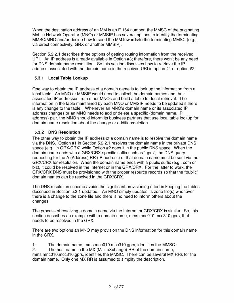
When the destination address of an MM is an E.164 number, the MMSC of the originating Mobile Network Operator (MNO) or MMSIP has several options to identify the terminating MMSC/MNO and/or decide how to send the MM towards/to the terminating MMSC (e.g., via direct connectivity, GRX or another MMSIP). Section 5.2.2.1 describes three options of getting routing information from the received URI. An IP address is already available in Option #3; therefore, there won’t be any need for DNS domain name resolution. So this section discusses how to retrieve the IP address associated with the domain name in the received URI in option #1 or option #2.
5.3.1 Local Table Lookup One way to obtain the IP address of a domain name is to look up the information from a local table. An MNO or MMSIP would need to collect the domain names and their associated IP addresses from other MNOs and build a table for local retrieval. The information in the table maintained by each MNO or MMSIP needs to be updated if there is any change to the table. Whenever an MNO’s domain name or its associated IP address changes or an MNO needs to add or delete a specific (domain name, IP address) pair, the MNO should inform its business partners that use local table lookup for domain name resolution about the change or addition/deletion.
5.3.2 DNS Resolution The other way to obtain the IP address of a domain name is to resolve the domain name via the DNS. Option #1 in Section 5.2.2.1 resolves the domain name in the private DNS space (e.g., in GRX/CRX) while Option #2 does it in the public DNS space. When the domain name ends with a GRX/CRX-specific suffix such as “gprs”, the DNS query requesting for the A (Address) RR (IP address) of that domain name must be sent via the GRX/CRX for resolution. When the domain name ends with a public suffix (e.g., com or biz), it could be resolved in the Internet or in the GRX/CRX. For the latter to work, the GRX/CRX DNS must be provisioned with the proper resource records so that the “public” domain names can be resolved in the GRX/CRX. The DNS resolution scheme avoids the significant provisioning effort in keeping the tables described in Section 5.3.1 updated. An MNO simply updates its zone file(s) whenever there is a change to the zone file and there is no need to inform others about the changes. The process of resolving a domain name via the Internet or GRX/CRX is similar. So, this section describes an example with a domain name, mms.mnc010.mcc310.gprs, that needs to be resolved in the GRX. There are two options an MNO may provision the DNS information for this domain name in the GRX. 1. The domain name, mms.mnc010.mcc310.gprs, identifies the MMSC. 2. The host name in the MX (Mail eXchange) RR of the domain name, mms.mnc010.mcc310.gprs, identifies the MMSC. There can be several MX RRs for the domain name. Only one MX RR is assumed to simplify the description.

22 of 27
Some operators favor Option #1 so would not provision the MX RR in the GRX DNS. Others favor Option #2 so would provision the MX RR in the GRX DNS. The 3GPP/3GPP2 MMS specifications recommend that the MMSC, MMS hub/relay or the Message Transfer Agent (MTA) used by MMSC or MMS hub/relay request for the MX RR for “mms.mnc010.mcc310.gprs”. Assume that the MX RR contains a host name of “mmsc1.mnc010.mcc310.gprs”. The MMSC then requests for the A RR for “mmsc1.mnc010.mcc310.gprs”, if the A RR was not received together with the MX RR, and sends the MM to that IP address. If no MX RR exists for “mms.mnc010.mcc310.gprs”, the MMSC then requests for the A RR for “mms.mnc010.mcc310.gprs” and sends the MM to that IP address.
5.4 Vocoders, Encoding and Related Transcoding In order to ensure minimum support and compatibility between multimedia messaging capable terminals, a MMS User Agent supporting specific media types should comply with the MM Content Classes section of OMA MMS Conformance Document V1.2 [R07]. Normally, the terminating operator is responsible for transcoding and delivery of MM to a recipient device. However, other transcoding arrangements could be agreed upon.
5.5 Billing It is recommended to use the “Bill and Keep” [R10] approach as the charging and billing principle between the GSMNA and CDMA network operators for MMS traffic. This method is currently employed in North America for inter-operator SMS service. The following are the key points about the “bill and keep” approach:
• No wholesale billing between operators. • No exchange of records between operators since there is no wholesale billing • Each operator can retail bill their own subscribers for mobile terminated MMS
messages as they deem appropriate • Since there is no impact regarding inter-operator information exchange, this
approach can be implemented immediately upon network readiness. In the future, the operators may decide to use a more sophisticated billing principle to account for and settle MMS traffic between operators.
5.6 Recommendations Based on the analysis made in Section 5, the following recommendations are agreed:
1. MM4 Transport: it is recommended to use MMSIP as a primary means to transport MM4 messages between GSM and CDMA operators. However under mutual agreement, both Bilateral Direct Connection and Dedicated Exchange Backbone Connection could also be used.
2. Recipient Address (E164 Number) Resolution: it is recommended to use Operator ENUM to resolve an E.164 number into a target MMSC routing address. The domain name for each E.164 number should be suffixed with the string “.e164enum.net” as described in section 5.2.2 and should always return number portability-corrected responses.
23 of 27
3. MMSC Address Resolution Using DNS: it is recommended that MMSC should use “.gprs” TLD for DNS query. It is possible to use local table lookup instead of using DNS for the target MMSC routing address.
4. It is recommended to follow OMA MMS Conformance V1.2 [R07] for MM contents exchanged between GSM and CDMA operators.
5. It is recommended that “Bill and Keep” should be used as the charging and billing principle between GSM and CDMA operators.
6 Service Behavior The Service Level Agreement (SLA) between the GSM and CDMA operators should comply with the requirements stated in [R07] and additionally should address the following administrative issues (which are to be settled between the operators without the support of the MMSCs):
1. Charging and billing The operators should employ the charging and billing mechanism as specified in section 5.5 of this document.
2. Data privacy The operators may recognize that restricted data privacy regulations/laws exist now or might exist in the future which could apply to MMS interworking. The national requirements for data privacy should be considered
3. Incident management The SLAs should identify and define the necessary communication channels between the GSM and CDMA operators to handle any incidents that might occur. The intent of this incident management are to isolate any problems to minimize the impacts to the MMS service and coordinate the needed repair and testing activities. Incident escalation process should be defined to resolve any inter-operator incidents in a timely fashion.
The SLAs also need to define the procedures and processes to manage any MMS network configuration changes, network upgrades and planned and unplanned maintenances to minimize the impacts to the MMS services
4. Responsibilities and contact information The SLAs should include the responsibilities and contact information for the dialog between the GSM and CDMA operators. This information should be as complete as possible to expedite any on-going and incident management.
5. Key Performance Indicators (KPI) The SLAs should define a set of key performance indicators to guarantee the quality of service. The following KPI should be agreed between the GSM and CDMA operators:
I. MMS Delivery Success Rate The agreement on Message Delivery Latency is optional 6. Transportation of delivery and read-reply reports

24 of 27
The transportation of delivery and read-reply reports should conform to Section 8 of [R10]. 3GPP and 3GPP2 specifications indicate that delivery and read-reply reports may traverse the same route as or different routes from the route used by the reported MMs. Therefore, each party within the message delivery chain should ensure the highest message delivery success rate within its network to achieve the best end-to-end MMS delivery success rate. In the case when the delivery and read-reply reports traverse the same route as the route used by the reported MMs, each of the involved parties within the message delivery chain has visibility to the total number of messages sent by it and the total number of messages that are reported to be received by it. In the case when the delivery and read-reply reports traverse routes different from the route used by the reported MMs, parties within the message delivery chain may or may not have visibility to the total number of messages sent and/or received. The SLAs between the GSM operators, CDMA operators and intermediary parties should include the route traversal preferences for the delivery report and read-reply reports.
6.1 Network Service Level Agreement (Network SLA) Service Level Agreements result from mutual business agreements, and may not be covered by the versions of the standards referred to by this report (e.g. [R01], [R04]). So, operators may use SLAs to reach the agreement on the capabilities they will mutually support. As such the operators should consider the following when establishing SLA on MMS:
• Inter-operator MM size limitation • Support of SMTP Message bundling (recommendation: no bundling) • Spamming and screening • Inter-operator maximum number of recipients per MM • If the other operator supports address hiding • The possibility for the other system to send or receive:
o end user requested delivery report, or o recipient MMS Relay/Server acknowledgement1 delivery report
• Support DRM (e.g., Forward Lock, Combined Delivery, Separate Delivery) • Support “SMTP Service Extension for Message Size Declaration” • Support “SMTP Service Extension for 8-bit MIME extension” • The Content Types supported by the recipient’s MMS R/S, so that the sender’s
MMS R/S can pre-adapt the MM before sending it to the recipient’s MMS R/S.
1 That functionality is not part of neither [R01] nor [R04], but will be part of the following release of these specifications.

25 of 27
An operator may opt to establish SLAs with each peer MMS R/S connection. The operator has ultimate accountability for defining roles and responsibilities for performance, maintenance and levels of support. It is also understood that provisioning and enforcement of SLAs is typically at the sole discretion of the operator.
6.2 MMS Interworking Provider Service Level Agreement When an MMSIP is used to provide MM4 connection between the GSM and CDMA operators, the MMS Interworking Provider should provide the same SLAs that are negotiated between these two operators; no service degradation should be detected. It is recommended that SLAs negotiated between any two operators should take into account of the additional transit/processing time introduced by the MMSIP.

26 of 27
Appendix A: KPI definition (Informative) This section provides a guideline on how KPI can be defined and agreed by different parties. MMS-IP A and MMS-IP B are optional. The values of KPIs should be negotiated by involved parties.
1. MMS Delivery Success Rate
To ensure that messages are delivered without loss, Message Delivery Success Rate is defined as the ratio between the total number of messages sent against the total number of messages received by a particular party in the message delivery chain such as the MMSC or the MMSIP. Each party in the message delivery chain should minimize message loss within its network to achieve the best end-to-end message delivery success rate.
Note: Not all received message are deliverable due to various reasons. Thus, the delivery success rate measurement done by each party should exclude any non-routable message. Also, messages may be retried due to various reasons. Thus, the successful rate measurement done by each party should also exclude retries. In order to substantiate the delivery success rate report, it is recommended that detailed delivery failure analysis reports are provided by each involved party. The messages includes the MMs and the delivery and read-reply reports
Originator MMS UA
RecipientMMS Relay/
Server
Recipient MMS UA
MM1_submit.REQ
MM4_forward.REQ
MM1_notification.REQ
Originator MMS Relay/
Server
MMSIPA
MMSIPB
MM4_forward.REQ
MM4_forward.REQ
The MMSIP A should ensure
minimum message loss of
message received and message sent
The MMSIP B should ensure
minimum message loss of
message received and message sent
Figure 9 - MMS Delivery Success Rate

27 of 27
2. Message Delivery Latency
To ensure a message can be delivered to the recipient end user in a timely manner, Message Delivery Latency is defined as the elapsed time between the time when a message is received and the time when that message is delivered by a particular party in the response delivery chain such as the MMSC or MMSIP. Each party in the message delivery chain should ensure the least message delivery latency within its network to achieve the best end-to-end message delivery latency. However end-to-end message delivery latency can not be measured by the originating operator under the current MMS standards, thus it is a performance measurement parameter that should be considered by the involved parties, but it is not enforced by this guideline document.
Originator MMS UA
RecipientMMS Relay/
Server
Recipient MMS UA
MM1_submit.REQ
MM4_forward.REQ
MM1_notification.REQ
Originator MMS Relay/
Server
MMSIPA
MMSIPB
MM4_forward.REQ
MM4_forward.REQ
End-to-end Message Delivery Latency
Originating operator should ensure least
Message Delivery Latency
MMSIP Ashould ensure least
Message Delivery Latency
MMSIP Bshould ensure least
Message Delivery Latency
Recipient operatorshould ensure least
Message Delivery Latency
Figure 10 - MMS Delivery Latency