MMC Capacitor Voltage Balancing in Nearest Level Control
21
MMC CAPACITOR VOLTAGE BALANCING IN NEAREST LEVEL CONTROL Mattia Ricco Aalborg University, Energy Technology Department, Pontoppidanstæde 111, 9000 Aalborg, Denmark
Transcript of MMC Capacitor Voltage Balancing in Nearest Level Control

MMC CAPACITOR VOLTAGE BALANCING IN NEAREST LEVEL
CONTROL
Mattia Ricco
Aalborg University, Energy Technology Department, Pontoppidanstæde 111, 9000 Aalborg, Denmark
Outline
Introduction
Sorting Methods for NLC
Proposed Solutions:
• Sorting Networks
• Capacitor Voltage Mapping Strategy
Conclusions
14-06-2017

Structure of MMC
Phase C
Larm
Larm
#2
n
#1
#2
n
#1Phase B
Larm
Larm
#2
n
#1
#2
n
#1
Phase A
Larm
Larm
Idc
SM2,u
SMN,u
SM1,l
SM2,l
SMN,l
SM1,u
ia
ib
icVau
Val
S1
S2
VC
VSM
iSM C
D1
D2
Rarm
Rarm
Lg
Lg
Lggrid
iau
ial
Vdc/2
Vdc/2
Advantages: • Reduced harmonics • High modularity • Scalability • Low switching losses • High reliability • Fault tolerance Challenges: • Circulating Current Control • Loss balance among SMs • Capacitor Voltage Balancing • Complex control
3 14-06-2017

4
Control scheme of MMC
SM Selection
Sorting Method
Vref
VauC
Nau
iau
Outer Current Control
ialiau
CVB
ia
+ - --
Nal
lowerupper
ValC
N
ial
Switching pulses
N
NN
NLC
NLC
* / * /
Vdc
1/2
+ +Vref,l Vref,u
Averaging Control
Circulating Current Control
++
ΣVC
Maximum Sampling Period Ts:
𝑇𝑇𝑠𝑠 =1
𝜋𝜋 𝑁𝑁 𝑓𝑓1 N = number of SMs
f1 = 50 Hz
𝑇𝑇𝑒𝑒𝑒𝑒 ≤ 𝑇𝑇𝑠𝑠 SM
Selection
Sorting Method
Vref
VauC
Nau
iau
Outer Current Control
ialiau
CVB
ia
+ - --
Nal
lowerupper
ValC
N
ial
Switching pulses
N
NN
NLC
NLC
* / * /
Vdc
1/2
+ +Vref,l Vref,u
Averaging Control
Circulating Current Control
++
ΣVC
14-06-2017

Outline
Introduction
Sorting Methods for NLC
Proposed Solutions:
• Sorting Networks
• Capacitor Voltage Mapping Strategy
Conclusions
14-06-2017

6
Sorting Methods for NLC Bubble Sorting Algorithm
Advantage: • Easy to implement.
Drawbacks: • The execution time is not fixed and it depends on the input list. • The execution time increases when N grows.
14-06-2017
Max/Min Approach
Advantage: • Easy to implement. • The sorting method is avoided. • Less execution time than Bubble sorting algorithm.
Drawbacks: • If more than one SM has to be inserted, for example during faults, the
max/min method needs more sampling periods to insert the required SMs. This affects the control dynamic.

7
Sorting Methods for NLC Tolerance Band
Advantage: • Reduced switching frequency.
Drawbacks: • A sorting method is required.
14-06-2017

Outline
Introduction
Sorting Methods for NLC
Proposed Solutions:
• Sorting Networks
• Capacitor Voltage Mapping Strategy
Conclusions
14-06-2017
9
Sorting Networks
14-06-2017
0
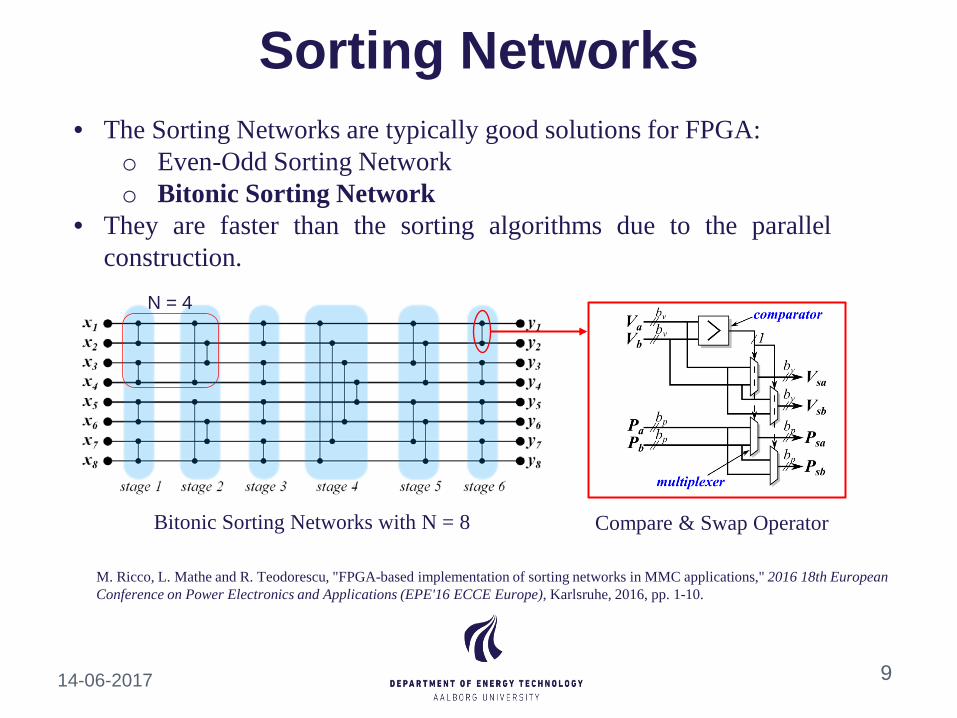
• The Sorting Networks are typically good solutions for FPGA: o Even-Odd Sorting Network o Bitonic Sorting Network
• They are faster than the sorting algorithms due to the parallel construction.
N = 4
Bitonic Sorting Networks with N = 8 Compare & Swap Operator
M. Ricco, L. Mathe and R. Teodorescu, "FPGA-based implementation of sorting networks in MMC applications," 2016 18th European Conference on Power Electronics and Applications (EPE'16 ECCE Europe), Karlsruhe, 2016, pp. 1-10.

10
Sorting Networks
14-06-2017
• The Sorting Networks are typically good solutions for FPGA: o Even-Odd Sorting Network o Bitonic Sorting Network
• They are faster than the sorting algorithms due to the parallel construction.
M. Ricco, L. Mathe and R. Teodorescu, "FPGA-based implementation of sorting networks in MMC applications," 2016 18th European Conference on Power Electronics and Applications (EPE'16 ECCE Europe), Karlsruhe, 2016, pp. 1-10.

Outline
Introduction
Sorting Methods for NLC
Proposed Solutions:
• Sorting Networks
• Capacitor Voltage Mapping Strategy
Conclusions
14-06-2017

12
Capacitor Voltage Mapping Strategy
14-06-2017
M. Ricco, L. Mathe and R. Teodorescu, "New MMC capacitor voltage balancing using sorting-less strategy in nearest level control," 2016 IEEE Energy Conversion Congress and Exposition (ECCE), Milwaukee, WI, 2016, pp. 1-8.

13
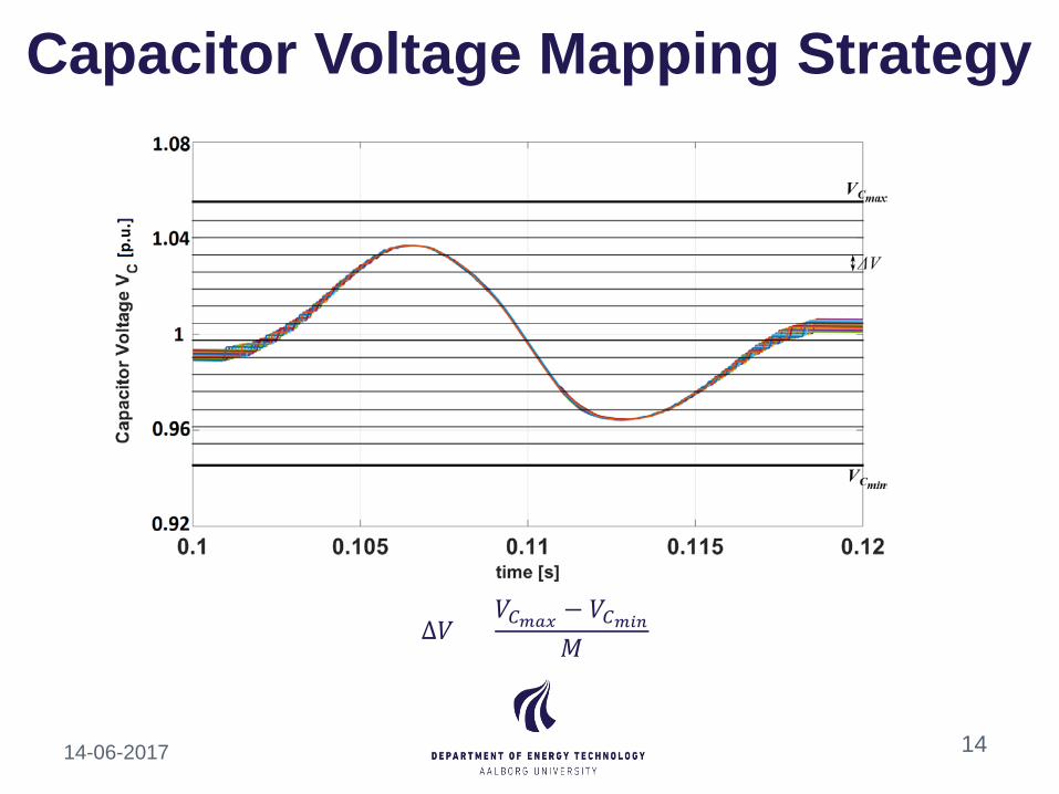
Capacitor Voltage Mapping Strategy
𝑉𝑉𝐶𝐶𝑚𝑚𝑚𝑚𝑚𝑚 and 𝑉𝑉𝐶𝐶𝑚𝑚𝑚𝑚𝑚𝑚 are derived from the design parameters.
14-06-2017
14
Capacitor Voltage Mapping Strategy
∆𝑉𝑉 = 𝑉𝑉𝐶𝐶𝑚𝑚𝑚𝑚𝑚𝑚 − 𝑉𝑉𝐶𝐶𝑚𝑚𝑚𝑚𝑚𝑚
𝑀𝑀
14-06-2017

15
Capacitor Voltage Mapping Strategy
14-06-2017

16
Capacitor Voltage Mapping Strategy
• Inside a voltage range the capacitor voltage values are considered to be identical
• M FIFO Memory Voltage Resolution • Memory depth equal to N • The position is stored in the cell
14-06-2017
𝑉𝑉𝐶𝐶𝑚𝑚𝑚𝑚𝑚𝑚 = 14 V ΔV = 0,5 V

17
Simulation Results
14-06-2017
Bubble Sorting Algorithm
CVMS with M = 8
CVMS with M = 16
CVMS with M = 32
CVMS with M = 64
CVMS with M = 128
Parameter Value
DC-link Voltage 𝑉𝑉𝐷𝐷𝐶𝐶 200 kV
SM Capacitor 𝐶𝐶 36 µF
Arm Inductance 𝐿𝐿𝑎𝑎𝑎𝑎𝑎𝑎 50 mH
Arm Resistance 𝑅𝑅𝑎𝑎𝑎𝑎𝑎𝑎 1 Ω
Number of SM 𝑁𝑁 16
Sampling frequency 𝑓𝑓𝑠𝑠 10 kHz
Table: MMC parameters
Parameter Value Grid frequency 𝑓𝑓𝑔𝑔𝑎𝑎𝑔𝑔𝑔𝑔 50 Hz
Grid Voltage 𝑉𝑉𝑔𝑔𝑎𝑎𝑔𝑔𝑔𝑔 121.2 kV
Grid Inductance 𝐿𝐿𝑔𝑔𝑎𝑎𝑔𝑔𝑔𝑔 16.7 mH
Grid Resistance 𝑅𝑅𝑔𝑔𝑎𝑎𝑔𝑔𝑔𝑔 0.52 Ω
Table: grid parameters

18
HIL Results
14-06-2017

Outline
Introduction
Sorting Methods for NLC
Proposed Solutions:
• Sorting Networks
• Capacitor Voltage Mapping Strategy
Conclusions
14-06-2017
20
Conclusions
Two solutions have been proposed for the capacitor voltage balancing algorithm: • Sorting Networks • Capacitor Voltage Mapping Strategy
The simulation results for the CVMS have been shown.
The HIL results have also been presented.
14-06-2017


![(e)MMC/SD/SDIO State of Affairsconnect.linaro.org.s3.amazonaws.com/sfo17... · First MMC stack by Russell King in kernel 2.6.9 [MMC] Add MMC core](https://static.fdocuments.us/doc/165x107/5f5ee69463a1e67f0c5f43dc/emmcsdsdio-state-of-first-mmc-stack-by-russell-king-in-kernel-269-mmc-add.jpg)