mM Monochrome Display and Printer Adapter - minus zero … - IBM Monochrome Display and...
32
--- - - - --- - --- - - --- - - - --- ---- Personal Computer ----- Hardware Reference --_.- Library mM Monochrome Display and Printer Adapter 6361511
Transcript of mM Monochrome Display and Printer Adapter - minus zero … - IBM Monochrome Display and...
--- -- - ---- ---- - ---- - - ------- Personal Computer ----- Hardware Reference--_.
Library
mM Monochrome Display and Printer Adapter
6361511
ii
Contents
Introduction ................................... 1 Monochrome Display Adapter Function .............. 1
Description ................................ 1 Programming Considerations .................. 5 Specifications .............................. 9
Printer Adapter Function ........................ 11 Description ............................... 11 Programming Considerations ................. 13 Specifications ............................. 17
Logic Diagrams ................................ 19
ill

iv
Introduction
The IBM Monochrome Display and Printer Adapter has two functions. The first is to provide an interface to the IBM
~ Monochrome Display. The second is to provide a parallel interface for the IBM Printers. We will discuss this adapter by function.
Monochrome Display Adapter Function
Description
The IBM Monochrome Display and Printer Adapter is designed around the Motorola 6845 CRT Controller module. There are 4K bytes of RAM on the adapter that are used for the display
.~ buffer. This buffer has two ports to which the system unit's microprocessor has direct access. No parity is provided on the display buffer.
Two bytes are fetched from the display buffer in 553 ns, providing a data rate of 1.8M bytes/second.
The adapter supports 256 different character codes. An 8K-byte character generator contains the fonts for the character codes. The characters, values, and screen characteristics are given in "Of Characters, Keystrokes, and Colors" in your Technical Reference system manual.
This adapter, when used with a display containing P39 phosphor, does not support a light pen.
Where possible, only one low-power Schottky (LS) load is present on any I/O slot. Some of the address bus lines have two LS loads. No signal has more than two LS loads.
Monochrome Adapter 1
Characteristics of the adapter are:
• Supports 80-character by 25-1ine screen
• Has direct-drive output
• Supports 9-PEL by 14-PEL character box
• Supports 7-PEL by 9-PEL character
• Has 18-kHz monitor
• Has character attributes
2 Monochrome Adapter
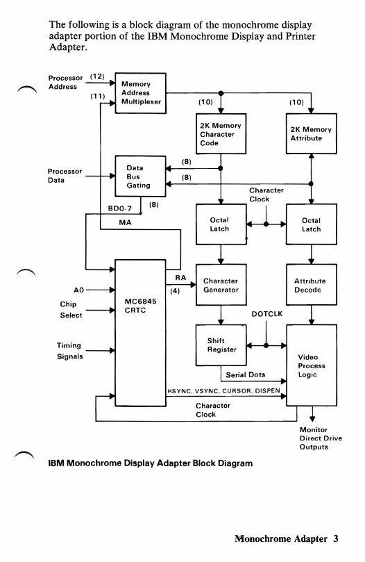
The following is a block diagram of the monochrome display adapter portion of the IBM Monochrome Display and Printer Adapter.
(12) Memory
Processor Address
Address (1~ Multiplexer (10) (10)
2K Memory 2K MemoryCharacter
Attribute Code
~ (8) DataProcessor ... Bus (8)Data Gating
Character Clock
1(8) ~ 1
BDO-7
Octal L.. Octal1 ..MA Latch Latch
.. f-
AO ..,.
RA ...
(4) ,. Character
Generator Attribute Decode
Chip
Select
Timing
..,.
..
MC6845 CRTC 1
Shift Register
DOTCLK
L... 1 .. Signals Video
Process Serial Dots Logic ..
HSYNC, VSYNC, CURSOR, DISPEN r Character Clock I +
Monitor Direct Drive Outputs
IBM Monochrome Display Adapter Block Diagram
Monochrome Adapter 3
4 Monochrome Adapter
---------
---------
---------
--------------------------- ----------- --
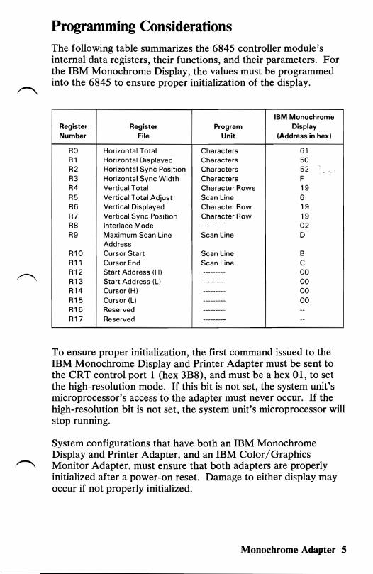
Programming Considerations The following table summarizes the 6845 controller module's internal data registers, their functions, and their parameters. For the IBM Monochrome Display, the values must be programmed into the 6845 to ensure proper initialization of the display.
Register Number
RO R1 R2 R3 R4 R5 R6 R7 R8 R9
R10 R11 R12 R13 R14 R15 R16 R17
Register File
Horizontal Total Horizontal Displayed Horizontal Sync Position Horizontal Sync Width Vertical Total Vertical Total Adjust Vertical Displayed Vertical Sync Position Interlace Mode Maximum Scan Line Address Cursor Start Cursor End Start Address (H) Start Address (L) Cursor (H) Cursor (L) Reserved Reserved
Program Unit
Characters Characters Characters Characters Character Rows Scan Line Character Row Character Row
Scan Line
Scan Line Scan Line
IBM Monochrome Display
(Address in hex)
61 50 52
~
-F 19 6 19 19 02 D
B C 00 00 00 00
To ensure proper initialization, the first command issued to the IBM Monochrome Display and Printer Adapter must be sent to the CRT control port 1 (hex 3B8), and must be a hex 01, to set the high-resolution mode. If this bit is not set, the system unit's microprocessor's access to the adapter must never occur. If the high-resolution bit is not set, the system unit's microprocessor will stop running.
System configurations that have both an IBM Monochrome Display and Printer Adapter, and an IBM Color/Graphics
r""\ Monitor Adapter, must ensure that both adapters are properly initialized after a power-on reset. Damage to either display may occur if not properly initialized.
Monochrome Adapter 5
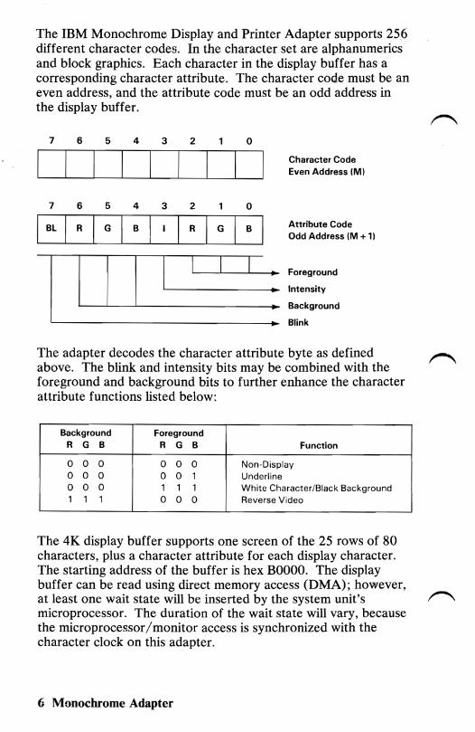
The IBM Monochrome Display and Printer Adapter supports 256 different character codes. In the character set are alphanumerics and block graphics. Each character in the display buffer has a corresponding character attribute. The character code must be an even address, and the attribute code must be an odd address in the display buffer.
r-... 7 6 5 4 3 2 0
Character Code Even Address 1M)
7 6 5 4 3 2 0
Attribute CodeBL I G I I GI R I B I R B I Odd Address 1M + 1)
Foreground
Intensity
I I I Background
I ~ Blink
The adapter decodes the character attribute byte as defined above. The blink and intensity bits may be combined with the foreground and background bits to further enhance the character attribute functions listed below:
Background Foreground R G B R G B Function
0 0 0 0 0 0 Non-Display 0 0 0 0 0 1 Underline 0 0 0 1 1 1 White Character/Black Background 1 1 1 0 0 0 Reverse Video
The 4K display buffer supports one screen of the 25 rows of 80 characters, plus a character attribute for each display character. The starting address of the buffer is hex BOOOO. The display buffer can be read using direct memory access (DMA); however, at least one wait state will be inserted by the system unit's microprocessor. The duration of the wait state will vary, because the microprocessor/monitor access is synchronized with the character clock on this adapter.
6 Monochrome Adapter

flc ;/
Interrupt level 7 is used on the parallel interface. Interrupts can be enabled or disabled through the printer control port. The interrupt is a high-level active signal.
The following table breaks down the functions of the I/O address decode for the adapter. The I/O address decode is from hex 3BO through hex 3BF. The bit assignment for each I/O address follows:
1/0 Register Address Function
3BO Not Used 3B1 Not Used 3B2 Not Used 3B3 Not Used 3B4 6845 Index Register 3B5 6845 Data Register 3B6 Not Used 3B7 Not Used 3B8 CRT Control Port 1 3B9 Reserved 3BA CRT Status Port 3BB Reserved 3BC Parallel Data Port 3BD Printer Status Port 3BE Printer Control Port 3BF Not Used
I/O Address and Bit Map
Monochrome Adapter 7
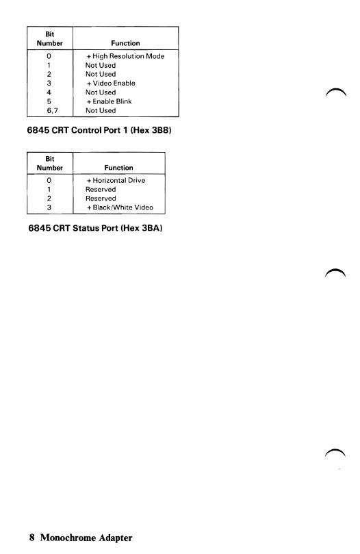
Bit Number Function
0 + High Resolution Mode 1 Not Used 2 Not Used 3 + Video Enable 4 Not Used 5 + Enable Blink 6,7 Not Used
6845 CRT Control Port 1 (Hex 3B8)
Bit Number Function
0 + Horizontal Drive 1 Reserved 2 Reserved 3 + Black/White Video
6845 CRT Status Port (Hex 3BA)
8 Monochrome Adapter
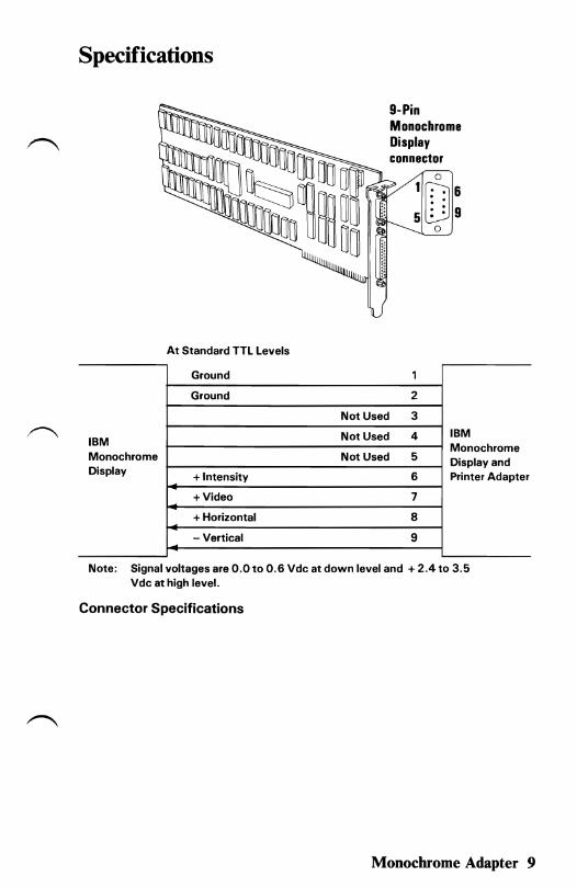
Specifications
9-Pin Monochrome Display connector
o
1~6 5l:!g
o
At Standard TTL Levels
Ground 1
Ground 2
Not Used 3
IBM Monochrome Display + Intensity
Not Used
Not Used
4
5
6
IBM Monochrome Display and Printer Adapter
+Video 7
+ Horizontal 8
- Vertical 9
Note: Signal voltages are 0.0 to 0.6 Vdc at down level and + 2.4 to 3.5 Vdc at high level.
Connector Specifications
Monochrome Adapter 9
10 Monochrome Adapter
Printer Adapter Function
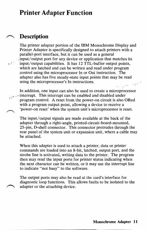
,...-.., Description
The printer adapter portion of the IBM Monochrome Display and Printer Adapter is specifically designed to attach printers with a parallel-port interface, but it can be used as a general
,input/output port for any device or application that matches its I" i input/output capabilities. It has 12 TTL-buffer output points,
which are latched and can be written and read under program control using the microprocessor In or Out instruction. The adapter also has five steady-state input points that may be read using the microprocessor's In instructions.
,),
In addition, one input can also be used to create a microprocessor , ~ _~' interrupt. This interrupt can be enabled and disabled under
',j .' program control. A reset from the power-on circuit is also ORed with a program output point, allowing a device to receive a
r""'\ 'power-on reset' when the system unit's microprocessor is reset.
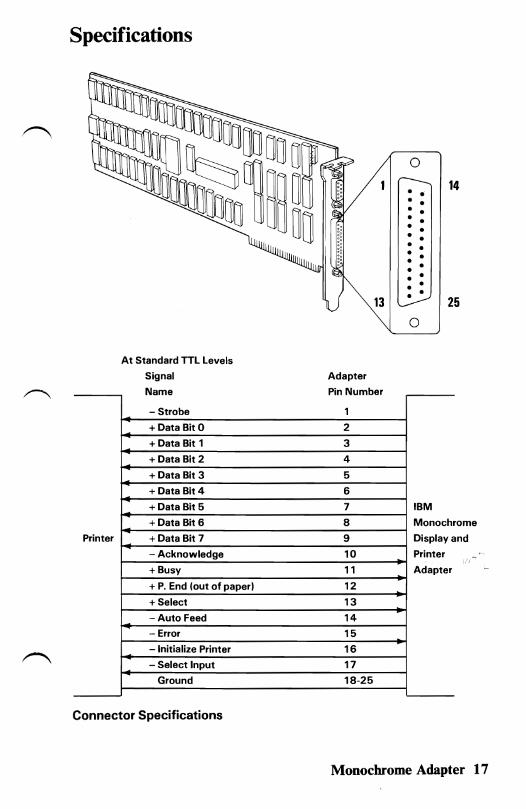
The input/output signals are made available at the back of the adapter through a right-angle, printed-circuit-board-mounted, 2S-pin, D-shell connector. This connector protrudes through the rear panel of the system unit or expansion unit, where a cable may be attached.
When this adapter is used to attach a printer, data or printer commands are loaded into an 8-bit, latched, output port, and the strobe line is activated, writing data to the printer. The program then may read the input ports for printer status indicating when the next character can be written, or it may use the interrupt line to indicate "not busy" to the software.
The output ports may also be read at the card's interface for diagnostic loop functions. This allows faults to be isolated to the
,...-.., adapter or the attaching device.
Monochrome Adapter 11
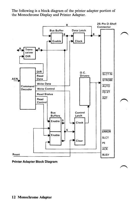
The following is a block diagram of the printer adapter portion of the Monochrome Display and Printer Adapter.
I 8 25-Pin D-Shell
I Connector
~us ButteJ..:r8~>-l~Data Latcl-h_~8~~
~ Enable .... Clock
Trans- J4..:8~>--+-___--4a-J ceiver ... .. r DIR
I,.........---
I DIR O.C. SLCTIN
Read Drivers DataA~ STROBE
I----,-~Write Data Command~------------~~ AUTO Decoder Write Control
FDXT Read Status
INITRead I Control
Bus Control Buffers Latch
~ Enable ~ 4 Clock I
.. 5
ERROR Enable
SLCT r-t Clear
PE
ACK
Reset BUSY
Printer Adapter Block Diagram
12 Monochrome Adapter
Programming Considerations
The printer adapter portion of the IBM Monochrome Display and Printer Adapter responds to five I/O instructions: two output and three input. The output instructions transfer data into 2 latches whose outputs are presented on pins of a 25-pin D-shell connector.
Two of the three input instructions allow the system unit's microprocessor to read back the contents of the two latches. The third allows the system unit's microprocessor to read the real-time status from a group of pins on the connector.
A description of each instruction follows.
IBM Monochrome Display & Printer Adapter
Output to address hex 3BC
Bit 7 Bit 6 Bit 5 Bit 4
Pin 9 Pin 8 Pin 7 Pin 6 I I
The instruction captures data from the data bus and is present on the respective pins. Each of these pins is capable of sourcing 2.6 rnA and sinking 24 rnA.
It is essential that the external device does not try to pull these lines to ground.
IBM Monochrome Display & Printer Adpater
Output to address hex 3BE
Bit 4
IRQ Enable
This instruction causes the latch to capture the five least significant bits of the data bus. The four least significant bits present their outputs, or inverted versions of their outputs, to the
Monochrome Adapter 13
respective pins as shown in the previous figure. If bit 4 is written as aI, the card will interrupt the system unit's microprocessor on the condition that pin 10 changes from high to low.
These pins are driven by open-collector drivers pulled to +5 Vdc through 4.7 kQ resistors. They can each sink approximately 7 rnA and maintain 0.8 volts down-level. ~
IBM Monochrome Display & Printer Adapter
Input from address hex 3BC
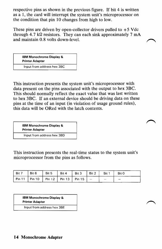
This instruction presents the system unit's microprocessor with data present on the pins associated with the output to hex 3BC. This should normally reflect the exact value that was last written to hex 3BC. If an external device should be driving data on these pins at the time of an input (in violation of usage ground rules), this data will be ORed with the latch contents.
IBM Monochrome Display & Printer Adapter
Input from address hex 3BD
This instruction presents the real-time status to the system unit's microprocessor from the pins as follows.
Bit 4 Bit 3 BitO
Pin 13 Pin 15
IBM Monochrome Display & Printer Adapter
Input from address hex 3BE
14 Monochrome Adapter
--
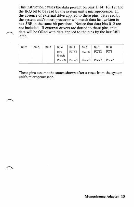
This instruction causes the data present on pins 1, 14, 16, 17, and the IRQ bit to be read by the system unit's microprocessor. In the absence of external drive applied to these pins, data read by the system unit's microprocessor will match data last written to hex 3BE in the same bit positions. Notice that data bits 0-2 are not included. If external drivers are dotted to these pins, that
~ data will be ORed with data applied to the pins by the hex 3BE latch.
Bit 7 Bit 6 Bit 5 Bit 4 Bit 3 Bit 2 Bit 1 BitO
IRQ Pin 17 Pin 16 Pin 14 Pin 1 Enable
Por=O Por = 1 Por=O Por= 1 Por = 1
These pins assume the states shown after a reset from the system unit's microprocessor.
Monochrome Adapter 1 S
16 Monochrome Adapter
• • • • • • • • • • • • •
• • • • • •
Specifications
At Standard TTL Levels
Signal
Name
- Strobe
+ Data Bit 0
+ Data Bit 1
+ Data Bit 2
+ Data Bit 3
+ Data Bit 4
+ Data Bit 5
+ Data Bit 6
Printer + Data Bit 7
- Acknowledge
+ Busy
+ P. End (out of paper)
+ Select
-Auto Feed
- Error
- Initialize Printer
- Select Input
Ground
Connector Specifications
13
Adapter
Pin Number
1
2
3
4
5
6
7
8
9
10
11
12
13
14
15
16
17
18-25
0
• • 14
•• ••
25
0
IBM
Monochrome
Display and
Printer
Adapter
Monochrome Adapter 17

18 Monochrome Adapter
- -
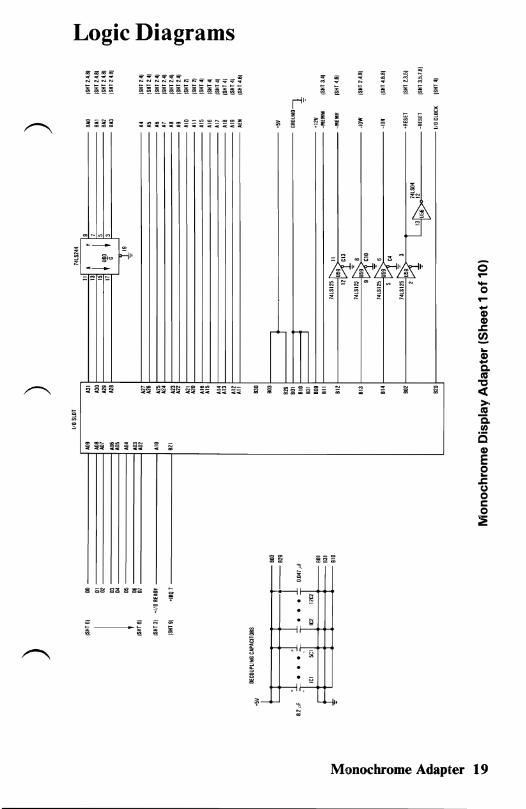
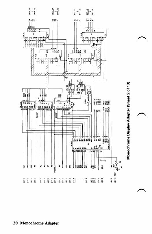
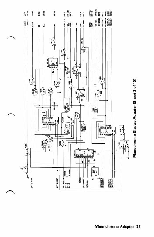
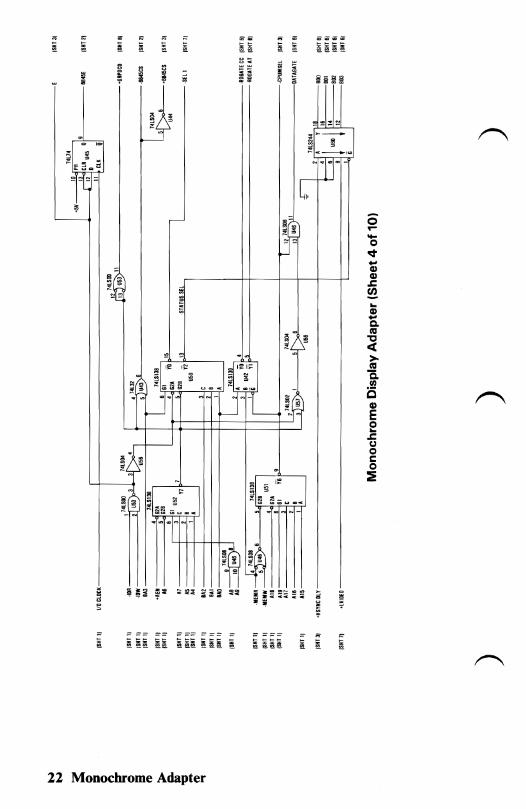
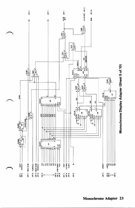
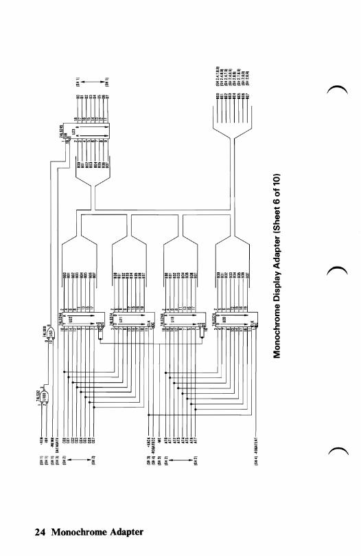
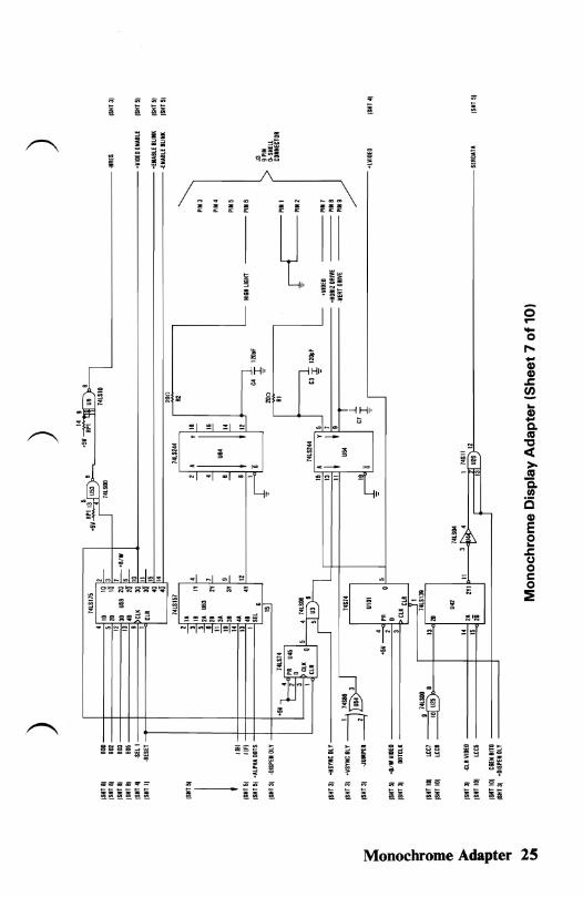
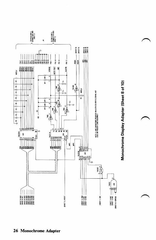
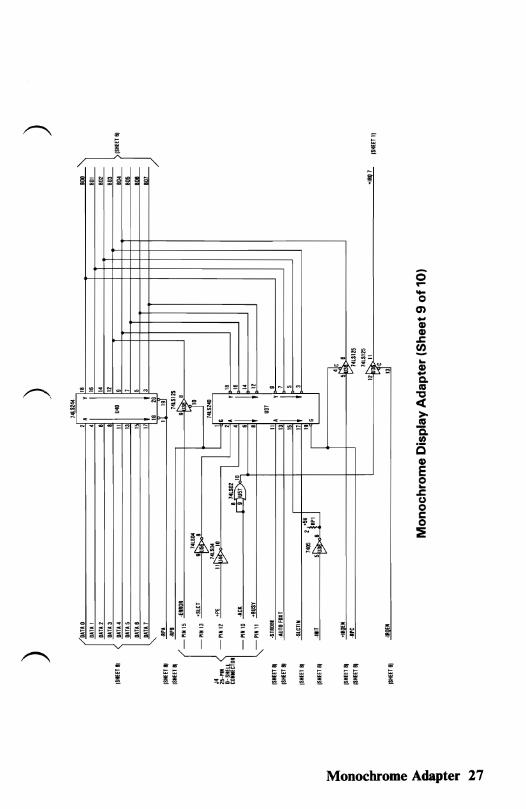
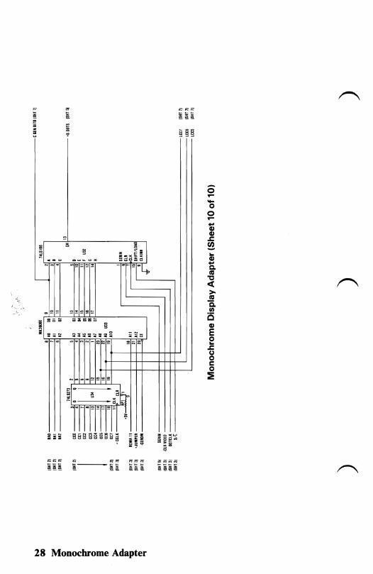
Logic Diagrams
.. ii5 ~ .; N '" ..
§.
f' "
"
" ~ if ~ -;" ~
~I=' I' ~ ~ 11-" " o ~ ~ ....
'" ~ ~
~ >'l >'l .... § '" §
~ N
o~ ~" "
... Q).... Q. co
"0 « >. co c.. III o Q)
E o... ~ CJ o s:::: o 2:
'--1"
Monochrome Adapter 19
.. .. ~ ;dl~;; 6~6 ~~~'l-'" ! ~ ~ f! ~ ~ ~ ~
tHHHJ tHH~B ~5~S :c'C:c'C
o.... .... o ('II
; G) .r. !!l ... G).... c. (0
"C c:(
>(0
Q. (II
is G)
E o... .r. (,,) oc: o
::E
;~~ IL .~l ~[::fa: 'f
= =:;;:'::::'
!;; !;; " '" " - §. - - .. §. .. - §. - - - -
" ~ r------- '" ~e~
20 Monochrome Adapter
.. ~ ~ :! .. = 3~ t::"0E';;~~ '" ;; '"" '"
- ~ i i i "- ~ ~ ~ ~~ i. ~ii~-!l ~ 5l ;~~
,. ~ !! ~ ~ ~ ~;
!! ~~!~ ., ~ g ';;l lii 'f \l t;t ';' .- g~ ~ -;ar;'=f"
~
~ 1L'-------:=I--I-~~~ =
~o--
~f~ o.... .... " o
8Ie (\')~ lC ~ = ~ !\l ;o!. = ...--- CD
CD ~
~ .. ! Q. ftI
'tJ « >ftI C. 1/1
C ~·~~~r' - CD
= E .. Qo § o...
- i m ~ g:=; ~
I~~=" o U
C o :E
Monochrome Adapter 21
'" S'ciD'" " ~~~
~ ~ !l iii ii! :::~ ; I I~,I, , ~ = ;!
~v} :IE~CI~
e!2~=
-~
o.... 15 q... Q) Q)
.l: (/) .. Q)... Co III "C <C >III Q. III
i5 Q)
E ..o .l: U o c o :E
;!:::> ;!~~iiI ~!:l~a)!: ~ ...
~:Ii': : ~: == I: iiI:'" 0>::: ID 1ft ~ .:c CC c:C
=== =- == = c::;
i~~ ~i iii ~i~ i ~~i~ i a
22 Monochrome Adapter
;0 ;0 ~ -~ -
.,~ ~ ~~ "' '"
~
:=
~
~ ~g ~~c g
_ uu L
< :; < < « < < g ~ ~
~ !l ~~i ..,r"'\ ~
=
N N ;0 C')...., N=<:S" '" '" '" '" " '" ~ ~~---~ ~~ -
Monochrome Adapter 23
- -~---~
11111111
....s ... o co ~
CD CD .c ~l )l )l ) ... Q) ~
c. (II
"C « >(II
is. VI
C5 """'" CD ___ _ Q)
"" 0> - __N'" -- E e .c (,) oc: o :E
~
::l ;;' ~
N
24 Monochrome Adapter
~ iii iiiiii'
~ f! ~ ~
o.--------"1 I ... OS ...... Q) Q)
.s: ~ ... ! c. «I ~ ~ ~- :ll .1 <C~ =
c___ '''''' >«I
--- ~[. Q.II)
is Q)
E e.s: u oc: o :!:
~"-n ~~
.: .: ., ., ~ ~ ~ !;l "-, " g "
~ ': !'!' "
;;- ;;
~ l:; ,.i!' .. ~
'" '" '" "". "- "- i ii H ~ "- ~
Monochrome Adapter 2S
0~ -IHi' ... ~~~.:; -0
i- -iHi' co+-++---j---++1HI' !;i ....ffi Q)
Q)l- ii;
~ o u: .s::~---.,.,,-----=~:t-1f fr
:0 ~ I :0 ~
Q) ~ i!!l ....
CoI-ii ca
I- ~ "Ci; « I' Uu >
~~ ca u~ Q.~~ c:;~ i5
1/1
i~ Q)
E 0 ~
.s:: (J 0 t: 0 ~
IIIIII := ;~i "
~
26 Monochrome Adapter
- - - - - -
co _ N to) ~ ..., "" ,.. g ::;:; '" ~ .. i~~g~~~~/ '" - - .. .. ~'" '" I I TIT
~
~ ~ iO iO iO iO iOz~~
i iii - ~~z~ 1!
Monochrome Adapter 27
- -
~I c_ u
N ~.
'----
m~=
~180 s :IE = --C:.!-
0'... .... o o... .... Q) Q)
" .r:. i5 ~
z ~ ~ =....... <.::I::r;: ~~ij! ~ Q)
!il ~ I ... ....~O-
Q. - ~- -"~~I' co "0 <t >co C.
~.~ en i:Sa~:g8S
§ Q)
:::::l::l:C:::il:> ~~J e E ~.~ ~~~
N _
""Ii! .r:. u oc: o
N __
=~
11-· ---
~ ~
1Tm:ITI'(',
28 Monochrome Adapter


![Macintosh 12'' Monochrome Display - 12_monochrome_display[1]](https://static.fdocuments.us/doc/165x107/577cc74b1a28aba711a09159/macintosh-12-monochrome-display-12monochromedisplay1.jpg)