MLCAD - optional
21
1 MLCAD - optional • Freeware CAD package (for Windows) for building/exhibiting CAD files that detail Lego constructions • Part by part (and if set up for it, step by step) breakdown of construction • Rotation for different views • Tool to view constructions provided for the class via the web • Installation procedure: 1. Download and install LDRAW – http://www.ldraw.org/download/start/win/step1.shtml – Download ldraw027.exe and complete.exe to the directory in which you want the LDRAW directory – From the Start .. Run window execute cmd, then cd to the above directory and run ldraw027.exe –y (creates LDRAW directory, sets up ldraw) complete.exe –y (installs the latest parts library) ldraw\makelist.exe (creates the parts list) When it asks to sort by number or description it is best to select description 2. Download the mlcad zip file and extract to the LDRAW directory – http://www.lm-software.com/mlcad/ is the download site – Make sure the LDRAW directory contains the PARTS.LST file More MLCAD • The PARTS.LST file in the LDRAW directory includes almost all needed Lego parts • MLCAD files of user models can be included as parts – Taken automatically from the LDRAW\MODELS directory – To setup the LDRAW\MODELS directory • Copy the files from the “Models to install in LDRAW MODELS directory” section of the web page http://www.unf.edu/ccec/cis/cwinton/html/roboticsclass/f03/mlcad.html
Transcript of MLCAD - optional

1
MLCAD - optional• Freeware CAD package (for Windows) for
building/exhibiting CAD files that detail Lego constructions• Part by part (and if set up for it, step by step) breakdown of construction• Rotation for different views
• Tool to view constructions provided for the class via the web• Installation procedure:
1. Download and install LDRAW– http://www.ldraw.org/download/start/win/step1.shtml– Download ldraw027.exe and complete.exe to the directory in which you want the
LDRAW directory– From the Start .. Run window execute cmd, then cd to the above directory and run
ldraw027.exe –y (creates LDRAW directory, sets up ldraw)complete.exe –y (installs the latest parts library)ldraw\makelist.exe (creates the parts list)When it asks to sort by number or description it is best to select description
2. Download the mlcad zip file and extract to the LDRAW directory– http://www.lm-software.com/mlcad/ is the download site– Make sure the LDRAW directory contains the PARTS.LST file
More MLCAD
• The PARTS.LST file in the LDRAW directory includes almost all needed Lego parts
• MLCAD files of user models can be included as parts– Taken automatically from the LDRAW\MODELS
directory– To setup the LDRAW\MODELS directory
• Copy the files from the “Models to install in LDRAW MODELS directory” section of the web page
http://www.unf.edu/ccec/cis/cwinton/html/roboticsclass/f03/mlcad.html
2
IC Software Package• The IC version 4.21 software is “donation” ware”
– It is free and can be freely distributed and used for personal and educational purposes
– If you like it and are looking for a tax deduction, please consider the KISS Institute
– If you would like to use IC 4 in a commercial product, contact the KISS Institute about licensing
• The latest version may be found at http://www.kipr.org/ic/• IC (Interactive C) 4.21 is a C compiler/interpreter
– Implements most of the ANSI C language– Interfaces to both the Handy Board and LEGO RCX– Interactively guides hardware setup requirements, loading firmware
(“pcode” interpreter) and key library functions onto the processor board– Provides an editor and on-line documentation– Provides an interactive environment for testing and debugging
IC vs. Regular C• #use – to specify files to download along with the
active file• Arrays and pointers are not interchangeable• For char s[16];
– s and &s[0] are not equivalent (including parametric usage)
• Array as parameters – format: <type> <array-name>[]
e.g., void foo(int x[], ...) { ... }
• Arithmetic on pointer types is not permitted
3
IC vs. Regular C (2)
• NULL is a special built-in pointer constant– NULL is not bound by type rules– an uninitialized pointer’s value tests as NULL– NULL can be assigned to an array variable
(useful when passing arrays as parameters):foo(NULL);
...void foo(int x[]){
if (x == NULL) ...}
IC vs. Regular C (3)
• The Boolean data type is not supported• Boolean operations are supported on type int, but
not on type long– AND (&&)– OR (||)– NOT (!)
• In a Boolean expression 0 is False and not 0 is True• Boolean operations return 0 or 1
4
IC vs. Regular C (4)
• Bitwise operators are supported on type int, but not on type long– AND (&)– OR (|)– NOT (~)– XOR (^)– shift (<<, >>)
• Division is not supported on type long
IC vs. Regular C (5)
• Type char can only be used with arrays– char x[2] = "x"; --- is OK– char x = 'x'; --- is NOT OK
• Operations on characters in an array are actually done by coersion to intchar x[5],y[7]; ...x[3] = y[1]; --- y coerced to int

5
IC vs. Regular C (6)• Libraries are substantially different
– IC has a special library for each supported board– printf is constrained by limited display capability
• int has 4 formats (long is coerced to int for printf)– %d– %x to print as 4 hex characters– %b to print low byte as an 8-bit binary– %c to print low byte as an ASCII character (characters
from an array are coerced to int when operated on)• float format
– %f
• char array (string) format– %s
IC vs. Regular C (7)• Example
void main() {char x[3]="OK"; int y[3];y[0]=(int)x[0]; y[1]=(int)x[1];
...– printf("%d %d %c %c\n",y[0],y[1],y[0],y[1]);
displays "79 75 O K "– printf("%b %b %x %x\n",y[0],y[1],y[0],y[1]);
displays “01001111 01001011 004F 004B"

6
Setting Up• IC runs partly on the PC and partly on the
robot board• For IC to fully operate, a Handy Board or
RCX needs to be connected– The robot board needs to have the firmware
(pcode interpreter) loaded in order to be able to talk to IC
• The IC editor can be used without an attached robot board
To Install IC• On MacOS 8.6-9.2
– Double click on the MacOS .sit file• On a Mac OSX
– Double click on the OSX .tgz file• Note: keep the app and the library folders in the same
folder
• On Windows– Double click on the windows .exe file
• IC4 will be added to your Program Files directory
• On Linux– Extract from the tar archive to your directory
• Note: keep the app and the library directories in the same directory
7
Get Started with IC Environment• Start the IC application• Click on the picture of the Handy Board• Click on the Connect Later button• Click on the New button (upper left corner)• Type in a program that prints out a text string• Save the file using the Save button (name it
whatever you want -- just remember where you put it).
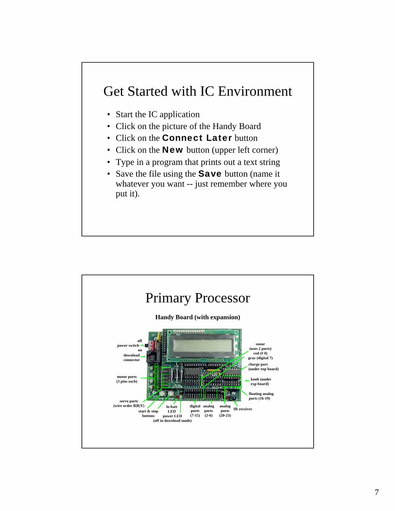
Primary Processor
charge port(under exp board)
knob (under exp board)
floating analog ports (16-19)
IR receiveranalogports
(20-23)
analogports(2-6)
digitalports(7-15)power LED
(off in download mode)
lo-battLEDstart & stop
buttons
servo ports(wire order B|R|Y)
motor ports(3 pins each)
downloadconnector
offpower switch
on
0
1
23
012345
sonar (uses 2 ports)
red (# 0)gray (digital 7)
Handy Board (with expansion)
8
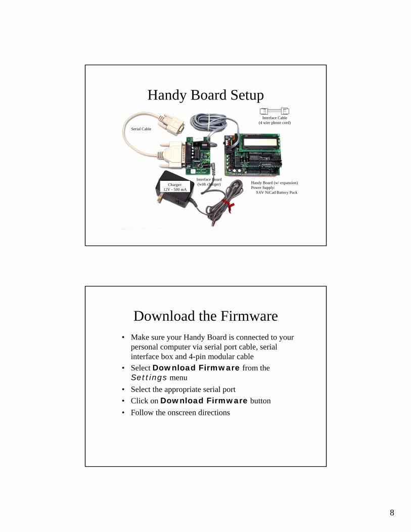
Handy Board Setup
Serial Cable
Interface Cable(4 wire phone cord)
Charger:12V - 500 mA
Interface Board(with charger) Handy Board (w/ expansion)
Power Supply: 9.6V NiCad Battery Pack
Download the Firmware• Make sure your Handy Board is connected to your
personal computer via serial port cable, serial interface box and 4-pin modular cable
• Select Download Firmware from the Settings menu
• Select the appropriate serial port• Click on Download Firmware button• Follow the onscreen directions
9
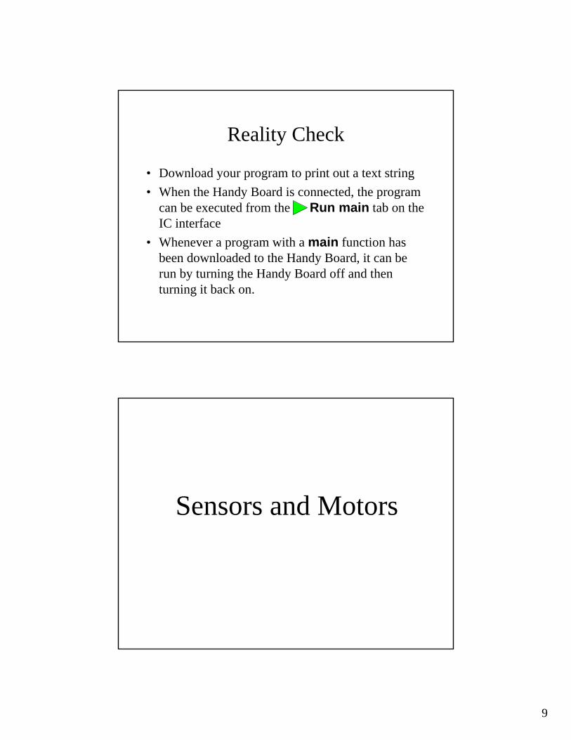
Reality Check
• Download your program to print out a text string• When the Handy Board is connected, the program
can be executed from the Run main tab on the IC interface
• Whenever a program with a main function has been downloaded to the Handy Board, it can be run by turning the Handy Board off and then turning it back on.
Sensors and Motors
10
Sensor Types• Digital:
– A sensor that returns a 0 or a 1– e.g. a switch (or bumper)
(open: 0, or closed: 1)• Analog:
– A sensor that returns a continuum of values– The processor digitizes the result in an 8-bit byte, which
limits values to the range of 0-255– e.g. a light sensor
(this type of sensor uses a photocell whose resistance decreases as light increases; ie., low values indicate lack of resistance, meaning a bright light is sensed)
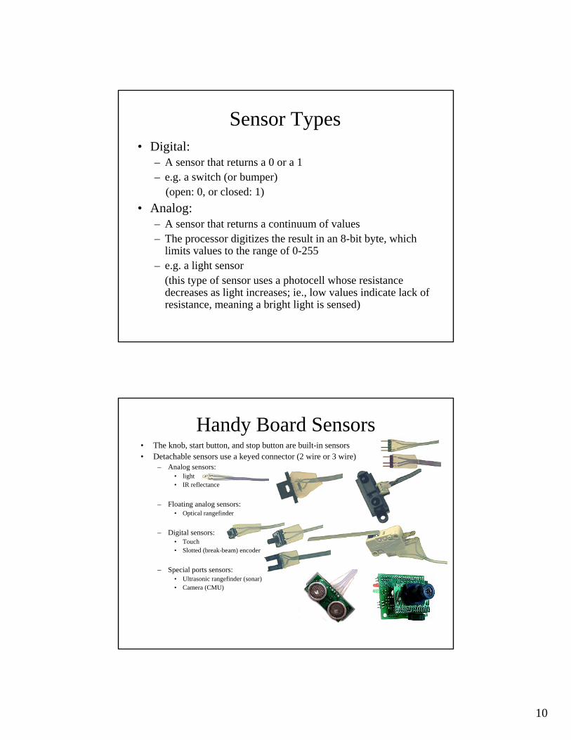
• The knob, start button, and stop button are built-in sensors• Detachable sensors use a keyed connector (2 wire or 3 wire)
– Analog sensors: • light• IR reflectance
– Floating analog sensors:• Optical rangefinder
– Digital sensors:• Touch• Slotted (break-beam) encoder
– Special ports sensors:• Ultrasonic rangefinder (sonar)• Camera (CMU)
Handy Board Sensors
11
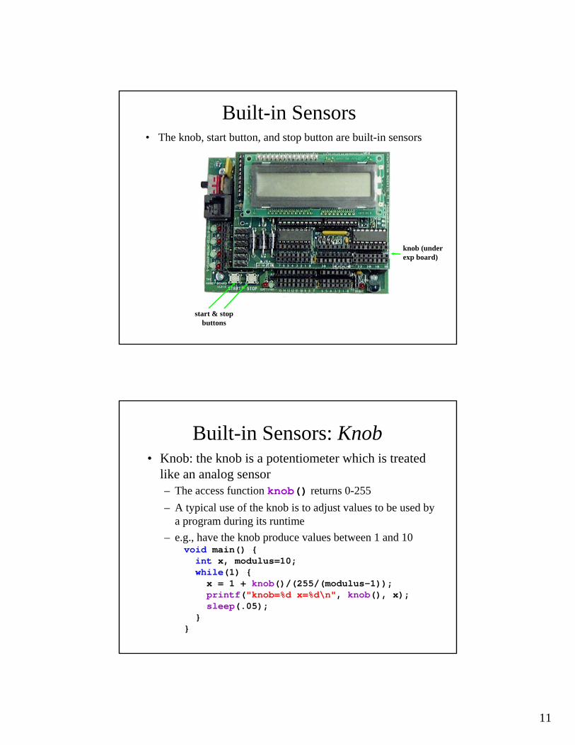
Built-in Sensors• The knob, start button, and stop button are built-in sensors
knob (under exp board)
start & stopbuttons
Built-in Sensors: Knob• Knob: the knob is a potentiometer which is treated
like an analog sensor– The access function knob() returns 0-255– A typical use of the knob is to adjust values to be used by
a program during its runtime– e.g., have the knob produce values between 1 and 10
void main() {int x, modulus=10;while(1) { x = 1 + knob()/(255/(modulus-1)); printf("knob=%d x=%d\n", knob(), x); sleep(.05);
}}
12
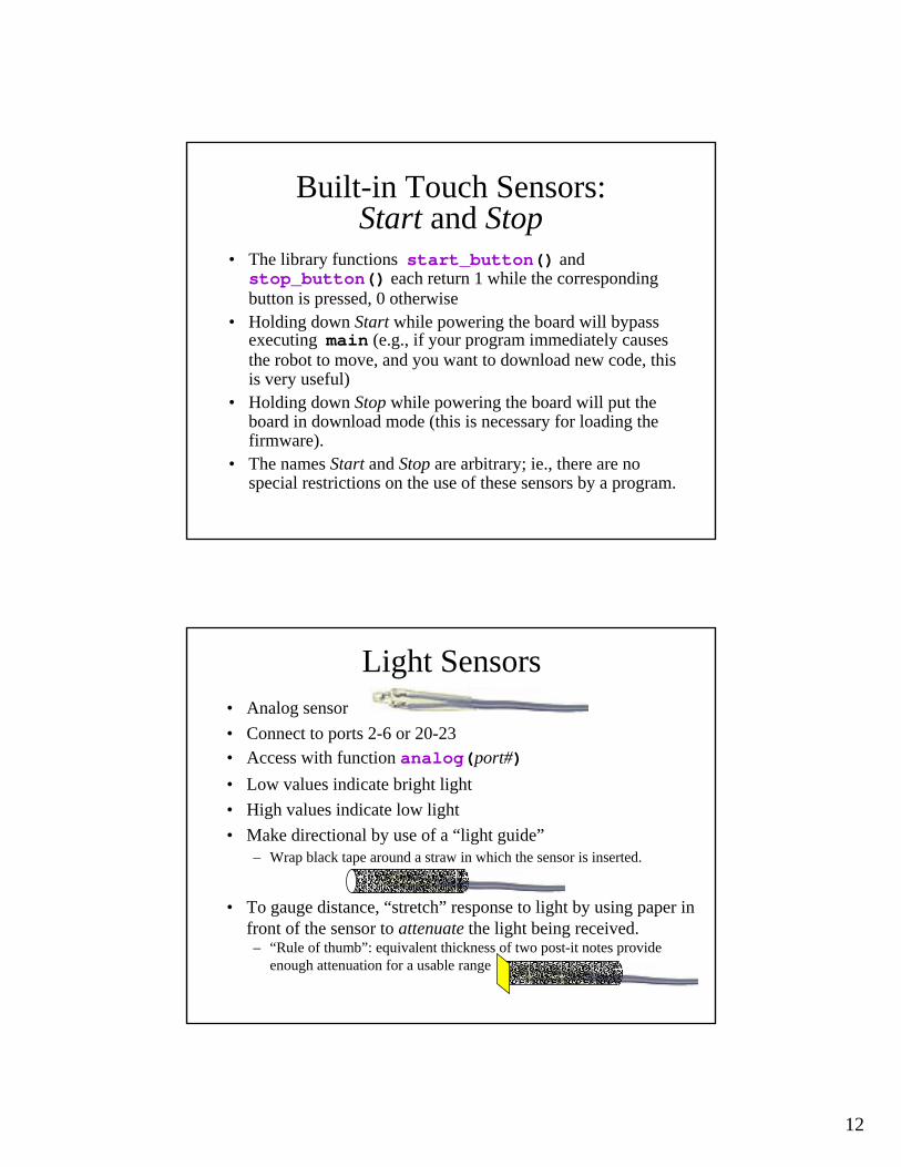
Built-in Touch Sensors:Start and Stop
• The library functions start_button() andstop_button() each return 1 while the corresponding button is pressed, 0 otherwise
• Holding down Start while powering the board will bypass executing main (e.g., if your program immediately causes the robot to move, and you want to download new code, this is very useful)
• Holding down Stop while powering the board will put the board in download mode (this is necessary for loading the firmware).
• The names Start and Stop are arbitrary; ie., there are no special restrictions on the use of these sensors by a program.
• Analog sensor• Connect to ports 2-6 or 20-23• Access with function analog(port#)• Low values indicate bright light• High values indicate low light• Make directional by use of a “light guide”
– Wrap black tape around a straw in which the sensor is inserted.
• To gauge distance, “stretch” response to light by using paper infront of the sensor to attenuate the light being received.– “Rule of thumb”: equivalent thickness of two post-it notes provide
enough attenuation for a usable range
Light Sensors
13
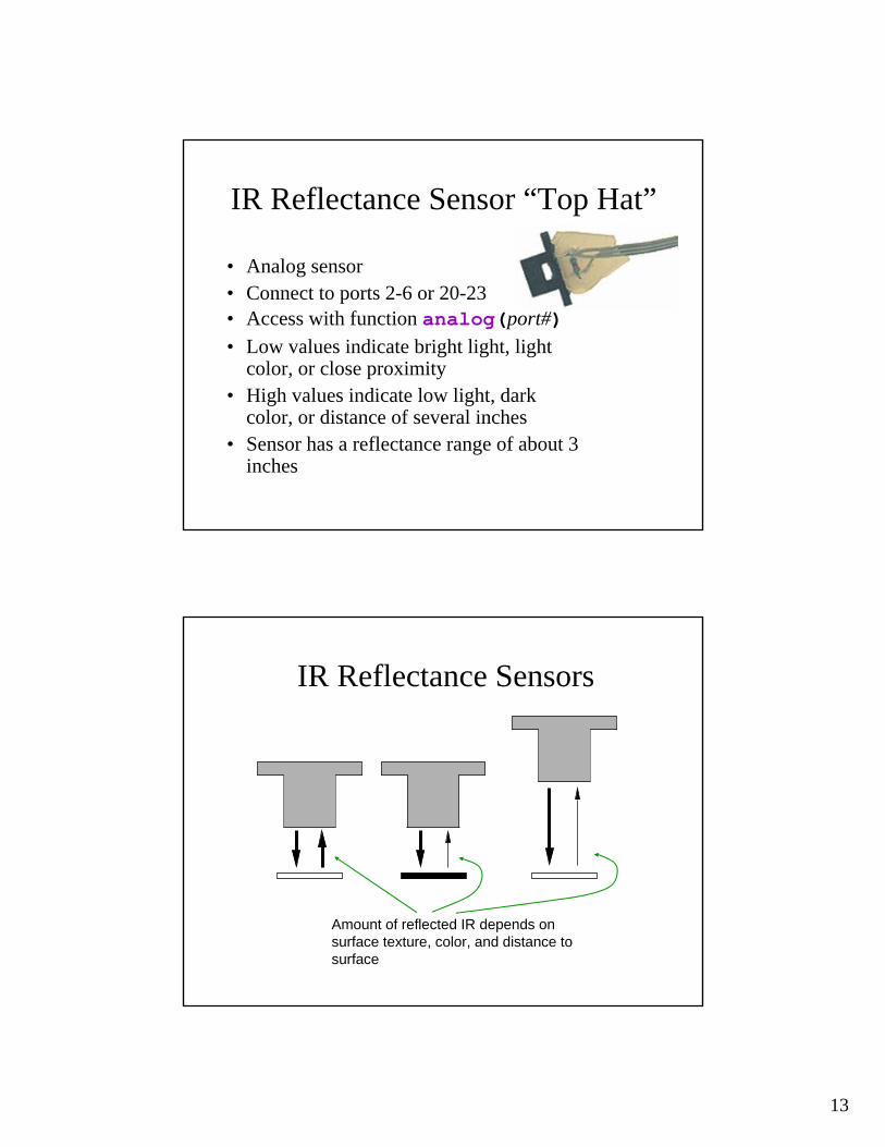
IR Reflectance Sensor “Top Hat”
• Analog sensor• Connect to ports 2-6 or 20-23• Access with function analog(port#)• Low values indicate bright light, light
color, or close proximity• High values indicate low light, dark
color, or distance of several inches• Sensor has a reflectance range of about 3
inches
IR Reflectance Sensors
Amount of reflected IR depends on surface texture, color, and distance to surface
14
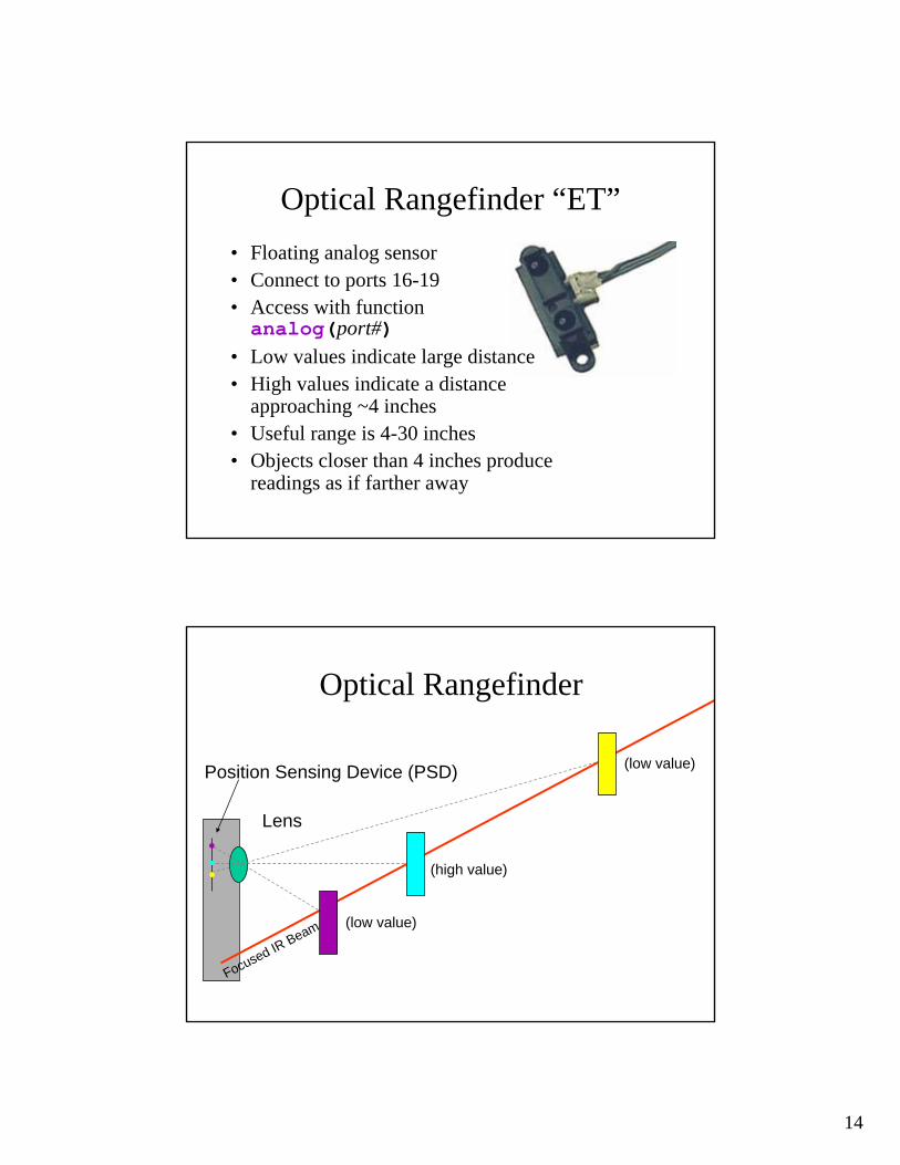
Optical Rangefinder “ET” • Floating analog sensor• Connect to ports 16-19• Access with function analog(port#)
• Low values indicate large distance• High values indicate a distance
approaching ~4 inches• Useful range is 4-30 inches• Objects closer than 4 inches produce
readings as if farther away
Optical Rangefinder
Focused IR Beam
Lens
Position Sensing Device (PSD)
(high value)
(low value)
(low value)

15
• Timed analog sensor• Connect red to Expansion board
– (upper deck) port #0• Connect gray to Digital #7• Access with function sonar()• Returned value is distance in mm to closest object in field
of view• Range is approximately 30-2000mm• No return (because objects are too close or too far) gives
value of 32767• Wait at least .03 seconds between sonar()calls
Ultrasonic Rangefinder (Sonar)
Ultrasonic Sensors• Puts out a short burst of high
frequency sound• Listens for the echo• Speed of sound is ~300mm/ms• sonar() times the echo,
divides by two and multiplies by speed of sound
• The sonar field of view is a 30o
teardropsonar
Area of coverage
16
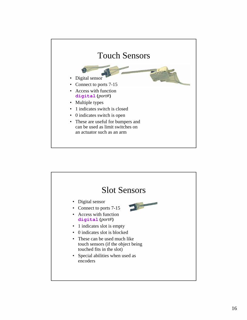
Touch Sensors
• Digital sensor• Connect to ports 7-15• Access with function digital(port#)
• Multiple types• 1 indicates switch is closed• 0 indicates switch is open• These are useful for bumpers and
can be used as limit switches on an actuator such as an arm
Slot Sensors • Digital sensor• Connect to ports 7-15• Access with function digital(port#)
• 1 indicates slot is empty• 0 indicates slot is blocked• These can be used much like
touch sensors (if the object being touched fits in the slot)
• Special abilities when used as encoders
17
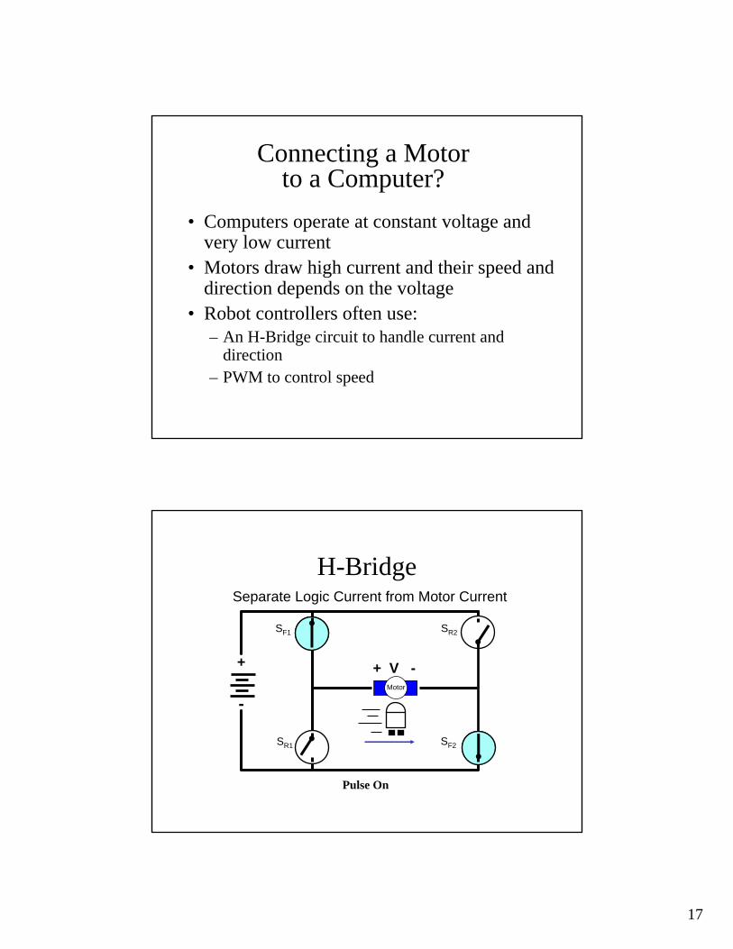
Connecting a Motor to a Computer?
• Computers operate at constant voltage and very low current
• Motors draw high current and their speed and direction depends on the voltage
• Robot controllers often use:– An H-Bridge circuit to handle current and
direction – PWM to control speed
H-BridgeSeparate Logic Current from Motor Current
+
-
+ V -
SF1
SR1
SR2
SF2
Motor
Pulse On
18
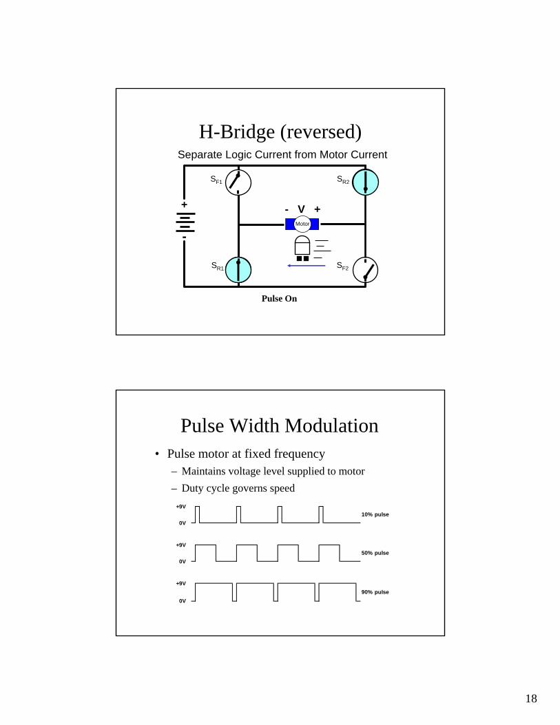
H-Bridge (reversed)Separate Logic Current from Motor Current
+
-
- V +
SF1
SR1
SR2
SF2
Motor
Pulse On
Pulse Width Modulation• Pulse motor at fixed frequency
– Maintains voltage level supplied to motor– Duty cycle governs speed
+9V
0V
10% pulse
50% pulse
90% pulse
0V
+9V
+9V
0V
19
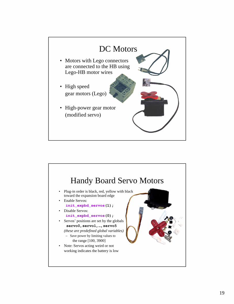
• Motors with Lego connectors are connected to the HB using Lego-HB motor wires
• High speed gear motors (Lego)
• High-power gear motor (modified servo)
DC Motors
Handy Board Servo Motors• Plug-in order is black, red, yellow with black
toward the expansion board edge• Enable Servos:
init_expbd_servos(1);• Disable Servos:
init_expbd_servos(0);• Servos’ positions are set by the globals
servo0,servo1,…,servo5(these are predefined global variables)– Save power by limiting values to
the range [100, 3900]• Note: Servos acting weird or not
working indicates the battery is low
20
Testing the Equipment• An IC program, hbtest.ic, is included in the tests subdirectory
of your IC 4 directory• Once started, the program employs the knob to select a category of
electronics to test– Motors for DC motors– Servos for servo motors– Digitals for touch sensors and break beam sensors– Analogs for light sensors, reflectance sensors, and proximity sensors
(recall that the optical proximity sensor uses the floating analog ports)– Knob for observing the knob output values– IR for testing the IR receiver– Sonar for testing the sonar (recall that the sonar utilizes 2 specific ports
in a specific manner)• hbtest.ic is a nice illustration of how to effectively use the knob
for selection purposes
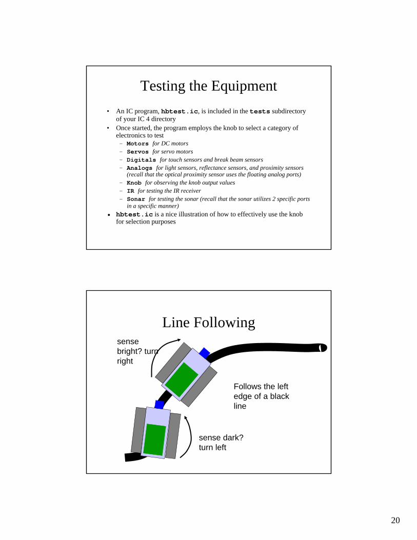
Line Following
Follows the left edge of a black line
sense dark? turn left
sense bright? turn right
21
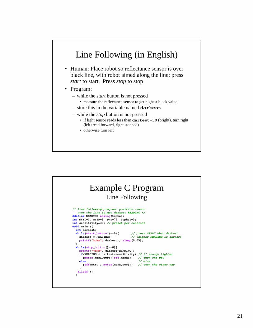
Line Following (in English)• Human: Place robot so reflectance sensor is over
black line, with robot aimed along the line; press start to start. Press stop to stop
• Program:– while the start button is not pressed
• measure the reflectance sensor to get highest black value– store this in the variable named darkest– while the stop button is not pressed
• if light sensor reads less than darkest-30 (bright), turn right (left tread forward, right stopped)
• otherwise turn left
Example C ProgramLine Following
/* line following program: position sensorover the line to get darkest READING */
#define READING analog(tophat)int mtrL=1, mtrR=3, pwr=75, tophat=3;int sensitivity=30; // preset per contrastvoid main(){ int darkest; while(start_button()==0){ // press START when darkestdarkest = READING; // (higher READING is darker)printf("%d\n", darkest); sleep(0.05);
} while(stop_button()==0){ printf("%d\n", darkest-READING); if(READING < darkest-sensitivity) // if enough lighter{motor(mtrL,pwr); off(mtrR);} // turn one way
else // else{off(mtrL); motor(mtrR,pwr);} // turn the other way
}alloff();}