MLC 520 EX - Tipteh d.o.o....5.2Access guarding ..... 19 5.3Danger zone guarding ..... 19...
64
SAFE IMPLEMENTATION AND OPERATION Original operating instructions EN 2018/08 - 50127400 We reserve the right to make technical changes MLC 520 EX Safety Light Curtains
Transcript of MLC 520 EX - Tipteh d.o.o....5.2Access guarding ..... 19 5.3Danger zone guarding ..... 19...
S A F E I M P L E M E N T A T I O N A N D O P E R A T I O NO r i g i n a l o p e r a t i n g i n s t r u c t i o n s
EN
201
8/08
- 50
1274
00W
e re
serv
e th
e rig
ht to
mak
e te
chni
cal c
hang
es
MLC 520 EXSafety Light Curtains

© 2018Leuze electronic GmbH & Co. KGIn der Braike 1D-73277 Owen / GermanyPhone: +49 7021 573-0Fax: +49 7021 573-199http://[email protected]
Leuze electronic MLC 520 EX 2
Table of contents
Leuze electronic MLC 520 EX 3
Table of contents
1 About this document ............................................................................................ 51.1 Used symbols and signal words ............................................................................................. 51.2 Checklists................................................................................................................................ 6
2 Safety ..................................................................................................................... 72.1 Intended use and foreseeable misuse.................................................................................... 72.1.1 Intended use........................................................................................................................ 72.1.2 Foreseeable misuse ............................................................................................................ 82.2 Necessary competencies........................................................................................................ 82.3 Responsibility for safety .......................................................................................................... 92.4 Disclaimer ............................................................................................................................... 92.5 Notices for the safe use of sensors in potentially explosive areas ......................................... 9
3 Device description .............................................................................................. 103.1 Device overview of the MLC family....................................................................................... 103.2 Connection technology ......................................................................................................... 123.3 Display elements .................................................................................................................. 123.3.1 Operating indicators on the MLC 500 transmitter.............................................................. 123.3.2 Operating indicators on the MLC 520 receiver.................................................................. 133.3.3 Alignment display .............................................................................................................. 15
4 Functions............................................................................................................. 164.1 Start/restart interlock RES .................................................................................................... 164.2 EDM contactor monitoring .................................................................................................... 164.3 Transmission channel changeover ....................................................................................... 174.4 Range reduction ................................................................................................................... 17
5 Applications ........................................................................................................ 185.1 Point of operation guarding................................................................................................... 185.2 Access guarding ................................................................................................................... 195.3 Danger zone guarding .......................................................................................................... 19
6 Mounting.............................................................................................................. 206.1 Arrangement of transmitter and receiver .............................................................................. 206.1.1 Calculation of safety distance S ........................................................................................ 206.1.2 Calculation of safety distance if protective fields act orthogonally to the approach direction....
216.1.3 Calculation of safety distance S for parallel approach to the protective field .................... 256.1.4 Minimum distance to reflective surfaces ........................................................................... 276.1.5 Preventing mutual interference between adjacent devices ............................................... 286.2 Mounting the safety sensor................................................................................................... 296.2.1 Suitable mounting locations .............................................................................................. 296.2.2 Definition of directions of movement ................................................................................. 306.2.3 Fastening via BT-NC60 sliding blocks............................................................................... 306.2.4 Fastening via BT-2HF swivel mount.................................................................................. 316.2.5 Fastening via BT-2SB10 swiveling mounting brackets ..................................................... 316.2.6 One-sided mounting on the machine table........................................................................ 326.3 Mounting accessories ........................................................................................................... 336.3.1 Deflecting mirror for multiple-side guarding....................................................................... 33
Table of contents
Leuze electronic MLC 520 EX 4
7 Electrical connection.......................................................................................... 357.1 Pin assignment transmitter and receiver .............................................................................. 367.1.1 MLC 500 transmitter .......................................................................................................... 367.1.2 MLC 520 receiver .............................................................................................................. 377.2 Circuit diagram examples ..................................................................................................... 397.2.1 MLC 520 circuit diagram example..................................................................................... 39
8 Starting up the device ........................................................................................ 408.1 Switching on ......................................................................................................................... 408.2 Aligning the sensor ............................................................................................................... 408.3 Aligning of deflecting mirrors with the laser alignment aid.................................................... 418.4 Unlocking start/restart interlock ............................................................................................ 42
9 Testing ................................................................................................................. 439.1 Before the initial start-up and following modifications........................................................... 439.1.1 Checklist for integrator – to be performed prior to the initial start-up and following modifica-
tions................................................................................................................................... 439.2 Regularly by qualified persons.............................................................................................. 459.3 Periodically by the operator .................................................................................................. 459.3.1 Checklist – periodically by the operator............................................................................. 46
10 Maintenance ........................................................................................................ 47
11 Troubleshooting.................................................................................................. 4811.1 What to do in case of failure? ............................................................................................... 4811.2 Operating indicators of the LEDs.......................................................................................... 4811.3 Error messages 7-segment display ...................................................................................... 49
12 Disposal ............................................................................................................... 52
13 Service and support ........................................................................................... 53
14 Technical data ..................................................................................................... 5414.1 General specifications .......................................................................................................... 5414.2 Dimensions, weight, response time ...................................................................................... 5614.3 Dimensioned drawings: Accessories .................................................................................... 57
15 Order guide and accessories............................................................................. 60
16 EC Declaration of Conformity............................................................................ 64
About this document
Leuze electronic MLC 520 EX 5
1 About this document
1.1 Used symbols and signal words
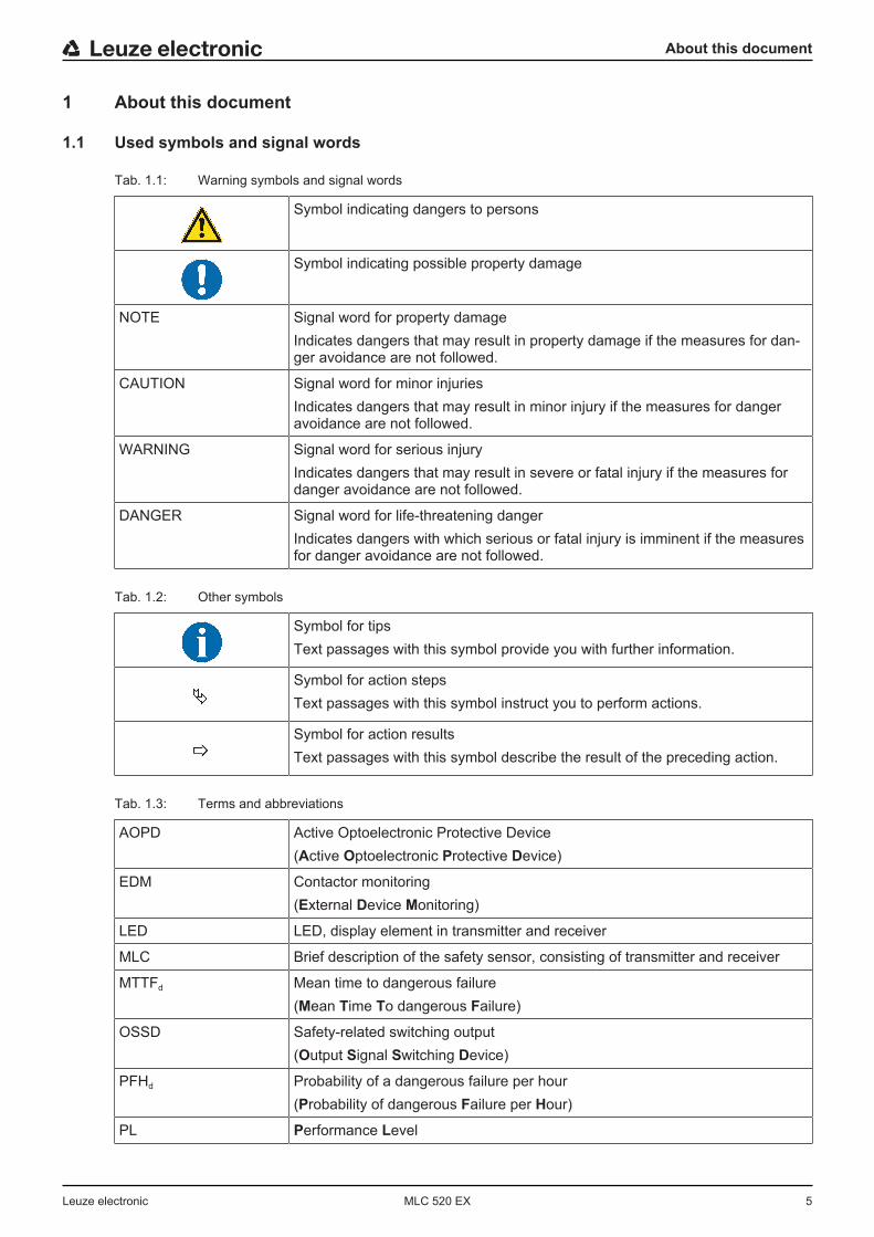
Tab. 1.1: Warning symbols and signal words
Symbol indicating dangers to persons
Symbol indicating possible property damage
NOTE Signal word for property damageIndicates dangers that may result in property damage if the measures for dan-ger avoidance are not followed.
CAUTION Signal word for minor injuriesIndicates dangers that may result in minor injury if the measures for dangeravoidance are not followed.
WARNING Signal word for serious injuryIndicates dangers that may result in severe or fatal injury if the measures fordanger avoidance are not followed.
DANGER Signal word for life-threatening dangerIndicates dangers with which serious or fatal injury is imminent if the measuresfor danger avoidance are not followed.
Tab. 1.2: Other symbols
Symbol for tipsText passages with this symbol provide you with further information.
Symbol for action stepsText passages with this symbol instruct you to perform actions.
Symbol for action resultsText passages with this symbol describe the result of the preceding action.
Tab. 1.3: Terms and abbreviations
AOPD Active Optoelectronic Protective Device(Active Optoelectronic Protective Device)
EDM Contactor monitoring(External Device Monitoring)
LED LED, display element in transmitter and receiver
MLC Brief description of the safety sensor, consisting of transmitter and receiver
MTTFd Mean time to dangerous failure(Mean Time To dangerous Failure)
OSSD Safety-related switching output(Output Signal Switching Device)
PFHd Probability of a dangerous failure per hour(Probability of dangerous Failure per Hour)
PL Performance Level
About this document
Leuze electronic MLC 520 EX 6
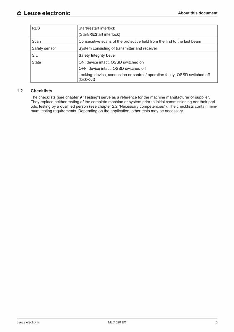
RES Start/restart interlock(Start/REStart interlock)
Scan Consecutive scans of the protective field from the first to the last beam
Safety sensor System consisting of transmitter and receiver
SIL Safety Integrity Level
State ON: device intact, OSSD switched onOFF: device intact, OSSD switched offLocking: device, connection or control / operation faulty, OSSD switched off(lock-out)
1.2 ChecklistsThe checklists (see chapter 9 "Testing") serve as a reference for the machine manufacturer or supplier.They replace neither testing of the complete machine or system prior to initial commissioning nor their peri-odic testing by a qualified person (see chapter 2.2 "Necessary competencies"). The checklists contain mini-mum testing requirements. Depending on the application, other tests may be necessary.
Safety
Leuze electronic MLC 520 EX 7
2 SafetyFor mounting, operating and testing, this document as well as all applicable national and international stan-dards, regulations, rules and directives must be observed. Relevant and supplied documents must be ob-served, printed out and handed to affected persons.Ä Before working with the safety sensor, completely read and observe the documents applicable to your
task.In particular, the following national and international legal regulations apply for the commissioning, techni-cal inspections and work with safety sensors:
• Machinery directive 2006/42/EC• Low voltage directive 2014/35/EU• EMC directive 2014/30/EU• Use of work equipment directive 89/655/EEC supplemented by directive 95/63 EC• OSHA 1910 Subpart O• Safety regulations• Accident-prevention regulations and safety rules• Ordinance on Industrial Safety and Health and employment protection act• Product Safety Law (ProdSG and 9. ProdSV)
NOTICE
For safety-related information you may also contact local authorities (e.g., industrial inspec-torate, employer's liability insurance association, labor inspectorate, occupational safety andhealth authority).
2.1 Intended use and foreseeable misuse
WARNING
A running machine may result in serious injury!Ä Make certain that the safety sensor is correctly connected and that the protective function of
the protective device is ensured.Ä Make certain that, during all conversions, maintenance work and inspections, the system is
securely shut down and protected against being restarted.
2.1.1 Intended use• The safety sensor may only be used after it has been selected in accordance with the respectively ap-
plicable instructions and relevant standards, rules and regulations regarding labor protection and safetyat work, and after it has been installed on the machine, connected, commissioned, and checked by acompetent person (see chapter 2.2 "Necessary competencies"). The devices are designed for indooruse only.
• When selecting the safety sensor it must be ensured that its safety-related capability meets or exceedsthe required performance level PLr ascertained in the risk assessment (see chapter 14.1 "Generalspecifications").
• The safety sensor protects persons or body parts at points of operation, danger zones or access pointsof machines and systems.
• With the “access guarding” function, the safety sensor detects persons only when they enter the dangerzone but cannot tell whether there are any persons inside the danger zone. For this reason, a start/restart interlock or a suitable stepping behind protection in the safety chain is essential in this case.
• The construction of the safety sensor must not be altered. When manipulating the safety sensor, theprotective function is no longer guaranteed. Manipulating the safety sensor also voids all warrantyclaims against the manufacturer of the safety sensor.
• The safety sensor must be inspected regularly by a competent person to ensure proper integration andmounting (see chapter 2.2 "Necessary competencies").
• The safety sensor must be exchanged after a maximum of 20 years. Repairs or the exchange of wearparts do not extend the mission time.

Safety
Leuze electronic MLC 520 EX 8
2.1.2 Foreseeable misuseAny use other than that defined under the “Approved purpose” or which goes beyond that use is consid-ered improper use.In principle, the safety sensor is not suitable as a protective device for use in the following cases:
• Danger posed by ejected objects or the spraying of hot or hazardous liquids from within the dangerzone
• Applications in explosive or easily flammable atmospheres
2.2 Necessary competenciesThe safety sensor may only be configured, installed, connected, commissioned, serviced and tested in itsrespective application by persons who are suitably qualified for the given task. General prerequisites forsuitably qualified persons:
• They have a suitable technical education.• They are familiar with the relevant parts of the operating instructions for the safety sensor and the oper-
ating instructions for the machine.Task-specific minimum requirements for suitably qualified persons:
ConfigurationSpecialist knowledge and experience in the selection and use of protective devices on machines as well asthe application of technical rules and the locally valid regulations on labor protection, safety at work andsafety technology.
MountingSpecialist knowledge and experience needed for the safe and correct installation and alignment of thesafety sensor with regard to the respective machine.
Electrical installationSpecialist knowledge and experience needed for the safe and correct electrical connection as well as safeintegration of the safety sensor in the safety-related control system.
Operation and maintenanceSpecialist knowledge and experience needed for the regular inspection and cleaning of the safety sensor –following instruction by the person responsible.
ServicingSpecialist knowledge and experience in the mounting, electrical installation and the operation and mainte-nance of the safety sensor in accordance with the requirements listed above.
Commissioning and testing• Experience and specialist knowledge in the rules and regulations of labor protection, safety at work and
safety technology that are necessary for being able to assess the safety of the machine and the use ofthe safety sensor, including experience with and knowledge of the measuring equipment necessary forperforming this work.
• In addition, a task related to the subject matter is performed in a timely manner and knowledge is keptup to date through continuous further training ‑ Competent person in terms of the German Betrieb-ssicherheitsverordnung (Ordinance on Industrial Safety and Health) or other national legal regulations.
Safety
Leuze electronic MLC 520 EX 9
2.3 Responsibility for safetyManufacturer and operator must ensure that the machine and implemented safety sensor function properlyand that all affected persons are adequately informed and trained.The type and content of all imparted information must not lead to unsafe actions by users.The manufacturer of the machine is responsible for:
• Safe machine construction• Safe implementation of the safety sensor, verified by the initial test performed by a competent person
(see chapter 2.2 "Necessary competencies")• Imparting all relevant information to the operating company• Adhering to all regulations and directives for the safe commissioning of the machine
The operator of the machine is responsible for:• Instructing the operator• Maintaining the safe operation of the machine• Adhering to all regulations and directives for labor protection and safety at work• Periodic testing by a competent person (see chapter 2.2 "Necessary competencies")
2.4 DisclaimerThe liability of Leuze electronic GmbH + Co. KG is to be excluded in the following cases:
• Safety sensor is not used as intended.• Safety notices are not adhered to.• Reasonably foreseeable misuse is not taken into account.• Mounting and electrical connection are not properly performed.• Proper function is not tested (see chapter 9 "Testing").• Changes (e.g., constructional) are made to the safety sensor.
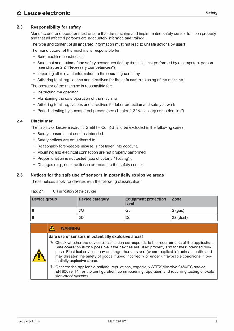
2.5 Notices for the safe use of sensors in potentially explosive areasThese notices apply for devices with the following classification:
Tab. 2.1: Classification of the devices
Device group Device category Equipment protectionlevel
Zone
II 3G Gc 2 (gas)
II 3D Dc 22 (dust)
WARNING
Safe use of sensors in potentially explosive areas!Ä Check whether the device classification corresponds to the requirements of the application.
Safe operation is only possible if the devices are used properly and for their intended pur-pose. Electrical devices may endanger humans and (where applicable) animal health, andmay threaten the safety of goods if used incorrectly or under unfavorable conditions in po-tentially explosive areas.
Ä Observe the applicable national regulations, especially ATEX directive 94/4/EC and/orEN 60079-14, for the configuration, commissioning, operation and recurring testing of explo-sion-proof systems.
Device description
Leuze electronic MLC 520 EX 10
3 Device descriptionThe safety sensors from the MLC 500 series are active opto-electronic protective devices. They satisfy thefollowing standards:
MLC 500
Type in accordance with EN IEC 61496 4
Category in accordance with EN ISO 13849 4
Performance Level (PL) in accordance with EN ISO 13849-1:2015 e
Safety Integrity Level (SIL) in accordance with IEC 61508 and SILCL in ac-cordance with EN IEC 62061
3
The safety sensors of the MLC 520 EX2 series satisfy the ATEX requirements in accordance withEN 60079-0, EN 60079-15, EN 60079-28 for category 3G as well as EN 60079-0 and EN 60079-31 for cat-egory 3D.The safety sensor consists of a transmitter and a receiver (see chapter 3.1 "Device overview of the MLCfamily"). It is protected against overvoltage and overcurrent acc. to IEC 60204-1 (protection class 3). Thesafety sensor is not dangerously influenced by ambient light (e.g., welding sparks, warning lights).
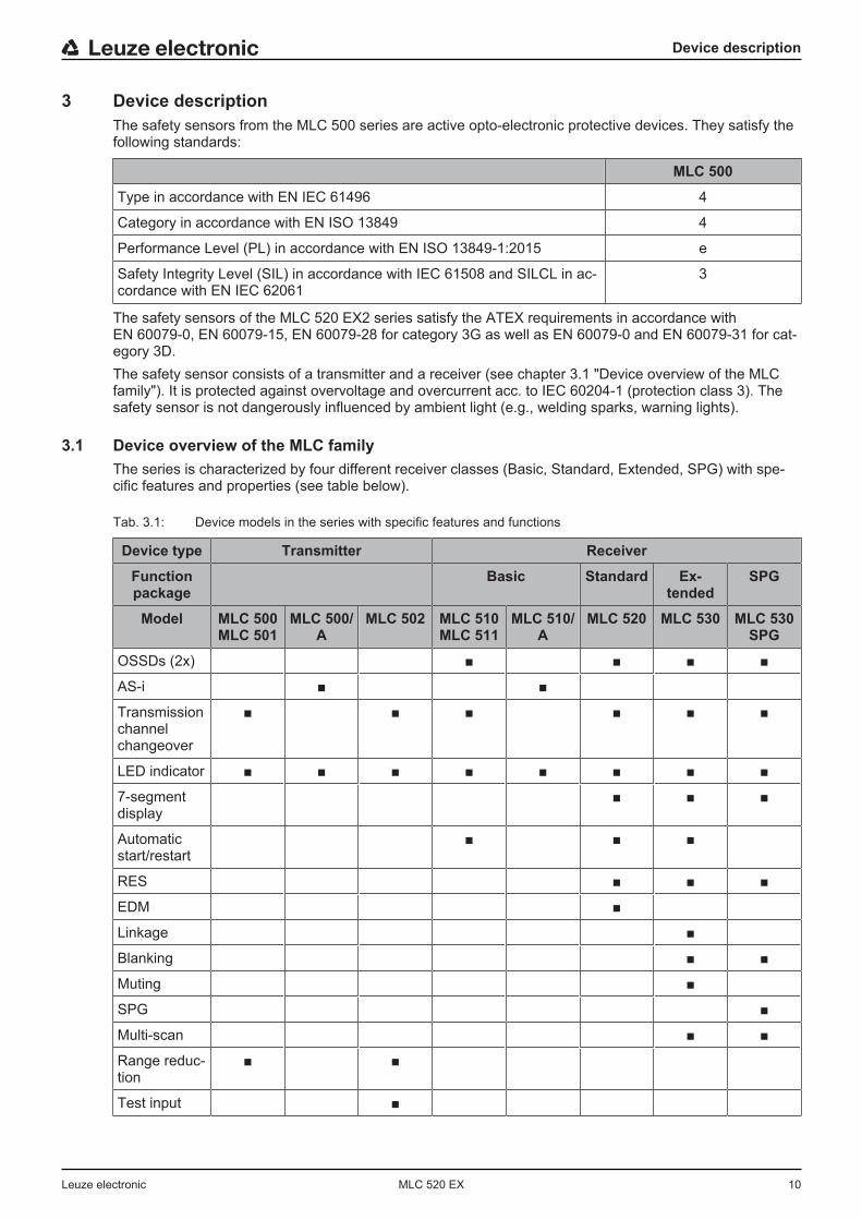
3.1 Device overview of the MLC familyThe series is characterized by four different receiver classes (Basic, Standard, Extended, SPG) with spe-cific features and properties (see table below).
Tab. 3.1: Device models in the series with specific features and functions
Device type Transmitter Receiver
Functionpackage
Basic Standard Ex-tended
SPG
Model MLC 500MLC 501
MLC 500/A
MLC 502 MLC 510MLC 511
MLC 510/A
MLC 520 MLC 530 MLC 530SPG
OSSDs (2x) ■ ■ ■ ■
AS-i ■ ■
Transmissionchannelchangeover
■ ■ ■ ■ ■ ■
LED indicator ■ ■ ■ ■ ■ ■ ■ ■
7‑segmentdisplay
■ ■ ■
Automaticstart/restart
■ ■ ■
RES ■ ■ ■
EDM ■
Linkage ■
Blanking ■ ■
Muting ■
SPG ■
Multi-scan ■ ■
Range reduc-tion
■ ■
Test input ■
Device description
Leuze electronic MLC 520 EX 11
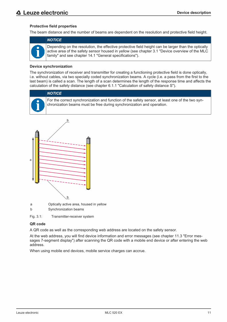
Protective field propertiesThe beam distance and the number of beams are dependent on the resolution and protective field height.
NOTICE
Depending on the resolution, the effective protective field height can be larger than the opticallyactive area of the safety sensor housed in yellow (see chapter 3.1 "Device overview of the MLCfamily" and see chapter 14.1 "General specifications").
Device synchronizationThe synchronization of receiver and transmitter for creating a functioning protective field is done optically,i.e. without cables, via two specially coded synchronization beams. A cycle (i.e. a pass from the first to thelast beam) is called a scan. The length of a scan determines the length of the response time and affects thecalculation of the safety distance (see chapter 6.1.1 "Calculation of safety distance S").
NOTICE
For the correct synchronization and function of the safety sensor, at least one of the two syn-chronization beams must be free during synchronization and operation.
a
b
b
a Optically active area, housed in yellowb Synchronization beams
Fig. 3.1: Transmitter-receiver system
QR codeA QR code as well as the corresponding web address are located on the safety sensor.At the web address, you will find device information and error messages (see chapter 11.3 "Error mes-sages 7-segment display") after scanning the QR code with a mobile end device or after entering the webaddress.When using mobile end devices, mobile service charges can accrue.
Device description
Leuze electronic MLC 520 EX 12
Fig. 3.2: QR code with corresponding web address (URL) on the safety sensor
3.2 Connection technologyThe transmitter and receiver feature an M12 connector as an interface to the machine control with the fol-lowing number of pins:
Device model Device type Device plug
MLC 500 Transmitter 5-pin
MLC 520 Standard receiver 8-pin
3.3 Display elementsThe display elements of the safety sensors simplify start-up and fault analysis.
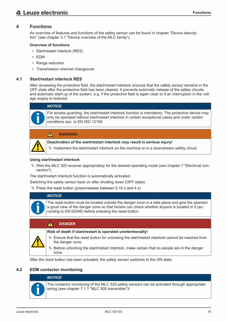
3.3.1 Operating indicators on the MLC 500 transmitterLocated in the connection cap on the transmitter are two LEDs which serve as function indicators:
1
2
1 LED1, green/red2 LED2, green
Fig. 3.3: Indicators on the MLC 500 transmitter
Tab. 3.2: Meaning of the LEDs on the transmitter
LED Color State Description
1 Green/red OFF Device switched off
Red Device error
Green Normal operation

Device description
Leuze electronic MLC 520 EX 13
LED Color State Description
2 Green Flashing For 10 s after switch-on: reducedrange selected by the wiring (seechapter 7.1 "Pin assignment trans-mitter and receiver").
OFF Transmission channel C1
ON Transmission channel C2
3.3.2 Operating indicators on the MLC 520 receiverTwo LEDs and a 7-segment display for showing the operating state are located on the receiver:
1 3
4
2
5
1 LED1, red/green2 LED2, yellow3 OSSD icon4 RES icon5 7‑segment display
Fig. 3.4: Indicators on the MLC 520 receiver
Tab. 3.3: Meaning of the LEDs on the receiver
LED Color State Description
1 Red/green OFF Device switched off
Red OSSD off
Red, flashing slowly (approx. 1 Hz) External error
Red, flashing fast (approx. 10 Hz) Internal error
Green, flashing slowly (ap-prox. 1 Hz)
OSSD on, weak signal
Green OSSD on
2 Yellow OFF • RES deactivated• or RES activated and enabled• or RES blocked and protective
field interrupted
ON RES activated and blocked butready to be unlocked - protectivefield free

Device description
Leuze electronic MLC 520 EX 14
7-segment display at the MLC 520 receiverIn normal operation, the 7-segment display shows the number of the selected transmission channel. In ad-dition, it helps during the detailed error diagnostics (see chapter 11 "Troubleshooting") and serves as analignment aid (see chapter 8.2 "Aligning the sensor").
Tab. 3.4: Meaning of the 7-segment display
Display Description
After switching on
8 Self test
t n n Response time (t) of the receiver in milliseconds (n n)
In normal operation
C1 Transmission channel C1
C2 Transmission channel C2
For alignment
Alignment display (see chapter 3.3.3 "Alignment display")• Segment 1: beam area in upper third of the protective field• Segment 2: beam area in middle third of the protective field• Segment 3: beam area in lower third of the protective field
For error diagnostics
F… Failure, internal device error
E… Error, external error
U… Usage info, application error
Tab. 3.5: Meaning of the 7-segment display
Display Description
After switching on
8 Self test
t n n Response time (t) of the receiver in milliseconds (n n)
In normal operation
C1 Transmission channel C1
C2 Transmission channel C2
For alignment
Alignment display (Alignment display).
For error diagnostics
F… Failure, internal device error
E… Error, external error
U… Usage info, application error
For error diagnostics, the error's respective letter is displayed first followed by the number code. The dis-play is repeated cyclically. An AutoReset is carried out after 10 s for errors that do not cause locking, withan unauthorized restart being impossible. In the case of blocking errors, the voltage supply must be sepa-rated and the cause of the error must be eliminated. Before switching on again, the steps taken before ini-tial commissioning must be repeated (see chapter 9.1 "Before the initial start-up and following modifica-tions").The 7-segment display switches to alignment mode when the device has not yet been aligned or when theprotective field has been interrupted (after 5 s). In this case, a fixed beam area from the protective field isassigned to every segment.
Device description
Leuze electronic MLC 520 EX 15
3.3.3 Alignment displayApproximately 5 s after a protective-field interruption, the 7-segment display switches to alignment mode.In this mode, one third of the total protective field (top, middle, bottom) is assigned to one of the three hori-zontal segments and the state of this sub-protective field displayed as follows:
Tab. 3.6: Function of alignment display
Segment Description
On All beams in the beam area are uninterrupted.
Flashing At least one, but not all beams in the beam area are uninterrupted.
Switched off All beams in the beam area are interrupted.
When the protective field has been free for about 5 s, the device switches back to the display of the operat-ing mode.
Functions
Leuze electronic MLC 520 EX 16
4 FunctionsAn overview of features and functions of the safety sensor can be found in chapter “Device descrip-tion” (see chapter 3.1 "Device overview of the MLC family").
Overview of functions• Start/restart interlock (RES)• EDM• Range reduction• Transmission channel changeover
4.1 Start/restart interlock RESAfter accessing the protective field, the start/restart interlock ensures that the safety sensor remains in theOFF state after the protective field has been cleared. It prevents automatic release of the safety circuitsand automatic start-up of the system, e.g. if the protective field is again clear or if an interruption in the volt-age supply is restored.
NOTICE
For access guarding, the start/restart interlock function is mandatory. The protective device mayonly be operated without start/restart interlock in certain exceptional cases and under certainconditions acc. to EN ISO 12100.
WARNING
Deactivation of the start/restart interlock may result in serious injury!Ä Implement the start/restart interlock on the machine or in a downstream safety circuit.
Using start/restart interlockÄ Wire the MLC 520 receiver appropriately for the desired operating mode (see chapter 7 "Electrical con-
nection").The start/restart interlock function is automatically activated.Switching the safety sensor back on after shutting down (OFF state):Ä Press the reset button (press/release between 0.15 s and 4 s)
NOTICE
The reset button must be located outside the danger zone in a safe place and give the operatora good view of the danger zone so that he/she can check whether anyone is located in it (ac-cording to EN 62046) before pressing the reset button.
DANGER
Risk of death if start/restart is operated unintentionally!Ä Ensure that the reset button for unlocking the start/restart interlock cannot be reached from
the danger zone.Ä Before unlocking the start/restart interlock, make certain that no people are in the danger
zone.
After the reset button has been actuated, the safety sensor switches to the ON state.
4.2 EDM contactor monitoring
NOTICE
The contactor monitoring of the MLC 520 safety sensors can be activated through appropriatewiring (see chapter 7.1.1 "MLC 500 transmitter")!
Functions
Leuze electronic MLC 520 EX 17
The “contactor monitoring” function monitors the contactors, relays or valves connected downstream of thesafety sensor. Prerequisite for this are switching elements with positive-guided feedback contacts (normallyclosed contacts).
Implement the contactor monitoring function:• through appropriate wiring of the MLC 520 safety sensors (see chapter 7.1.1 "MLC 500 transmitter").• through the external contactor monitoring of the downstream safety relay, (e.g. MSI series from Leuze
electronic)• or through contactor monitoring of the downstream safety PLC (optional, integrated via a safety bus)
If contactor monitoring is activated (see chapter 7 "Electrical connection"), it operates dynamically, i.e., inaddition to monitoring the closed feedback circuit every time before the OSSDs are switched on, it alsochecks whether the release of the feedback circuit opened within 500 ms and, after the OSSDs areswitched off, whether it has closed again within 500 ms. If this is not the case, the OSSDs return to theOFF state after being switched on briefly. An error message appears on the 7-segment display (E30, E31)and the receiver switches to the fault interlock state from which it can only be returned to normal operationby switching the supply voltage off and back on again.
4.3 Transmission channel changeoverTransmission channels are used to prevent mutual interference of safety sensors which are located closeto each other.
NOTICE
To guarantee reliable operation, the infrared beams are modulated so they can be discernedfrom the ambient light. Welding sparks or warning lights, e.g. from passing high-lift trucks,thereby do not influence the protective field.
With the factory setting, the safety sensor works in all operating modes with transmission channel C1.The transmission channel of the transmitter can be switched by changing the supply voltage polarity (seechapter 7.1.1 "MLC 500 transmitter").The transmission channel of the receiver can be switched by changing the supply voltage polarity (seechapter 7.1.2 "MLC 520 receiver").
NOTICE
Faulty function due to incorrect transmission channel!Select the same transmission channel on the transmitter and corresponding receiver.
4.4 Range reductionIn addition to selecting the suitable transmission channels (see chapter 4.3 "Transmission channelchangeover"), the range reduction also serves to prevent mutual interference of adjacent safety sensors.Activating the function reduces the light power of the transmitter so that around half of the nominal range isreached.
Reducing range:Ä Wire pin 4 (see chapter 7.1 "Pin assignment transmitter and receiver").ð The wiring of pin 4 determines the transmitting power and thereby the range.
WARNING
Impairment of the protective function due to incorrect transmitting power!The light power emitted from the transmitter is reduced through a single channel and withoutsafety-relevant monitoring.Ä Do not use this configuration option for safety purposes.Ä Note that the distance to reflective surfaces must always be selected so that no reflection
bypass can occur even at maximum transmitting power (see chapter 6.1.4 "Minimum dis-tance to reflective surfaces").
Applications
Leuze electronic MLC 520 EX 18
5 ApplicationsThe safety sensor only creates square protective fields.
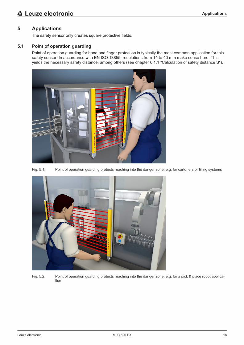
5.1 Point of operation guardingPoint of operation guarding for hand and finger protection is typically the most common application for thissafety sensor. In accordance with EN ISO 13855, resolutions from 14 to 40 mm make sense here. Thisyields the necessary safety distance, among others (see chapter 6.1.1 "Calculation of safety distance S").
Fig. 5.1: Point of operation guarding protects reaching into the danger zone, e.g. for cartoners or filling systems
Fig. 5.2: Point of operation guarding protects reaching into the danger zone, e.g. for a pick & place robot applica-tion
Applications
Leuze electronic MLC 520 EX 19
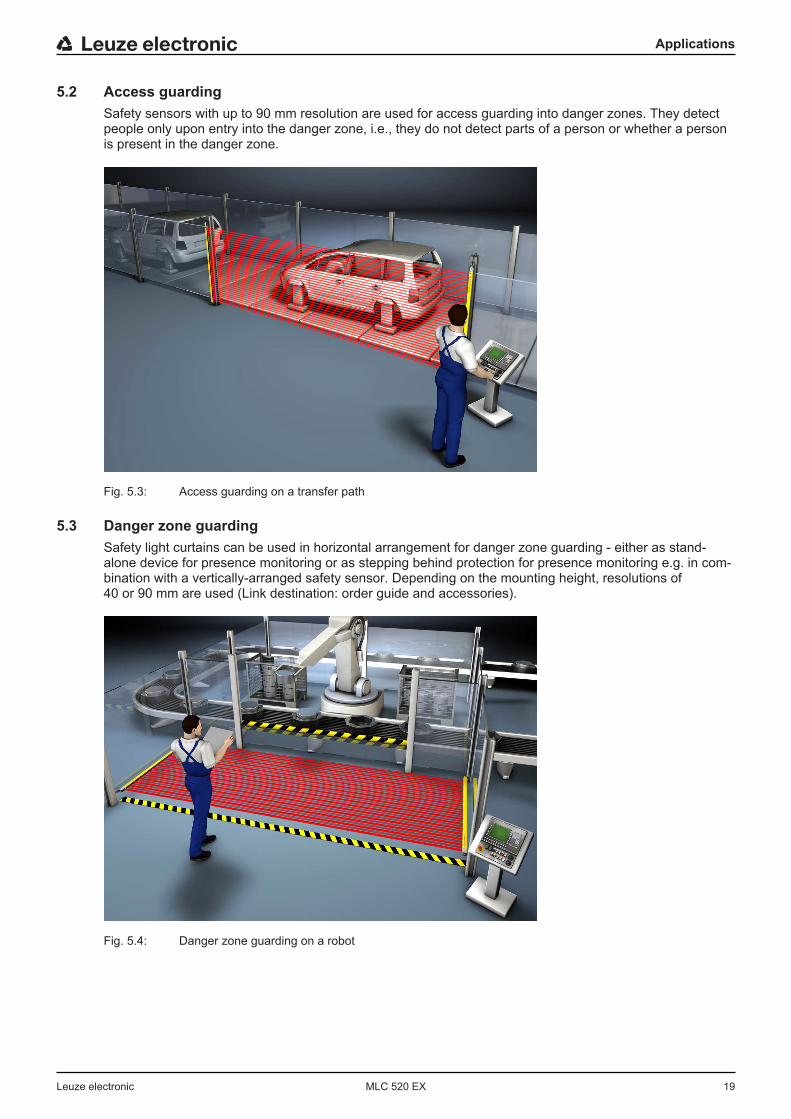
5.2 Access guardingSafety sensors with up to 90 mm resolution are used for access guarding into danger zones. They detectpeople only upon entry into the danger zone, i.e., they do not detect parts of a person or whether a personis present in the danger zone.
Fig. 5.3: Access guarding on a transfer path
5.3 Danger zone guardingSafety light curtains can be used in horizontal arrangement for danger zone guarding - either as stand-alone device for presence monitoring or as stepping behind protection for presence monitoring e.g. in com-bination with a vertically-arranged safety sensor. Depending on the mounting height, resolutions of40 or 90 mm are used (Link destination: order guide and accessories).
Fig. 5.4: Danger zone guarding on a robot
Mounting
Leuze electronic MLC 520 EX 20
6 Mounting
WARNING
Improper mounting may result in serious injury!The protective function of the safety sensor is only ensured if appropriately and professionallymounted for the respective, intended area of application.Ä Only allow the safety sensor to be installed by qualified persons (see chapter 2.2 "Neces-
sary competencies").Ä Maintain the necessary safety distances (see chapter 6.1.1 "Calculation of safety dis-
tance S").Ä Make sure that stepping behind, crawling under or stepping over the protective device is reli-
ably ruled out and reaching under, over or around is taken into account in the safety dis-tance, if applicable with additional distance CRO corresponding to EN ISO 13855.
Ä Take measures to prevent that the safety sensor can be used to gain access to the dangerzone, e.g. by stepping or climbing into it.
Ä Observe the relevant standards, regulations and these instructions.Ä Clean the transmitter and receiver at regular intervals: environmental conditions (see chap-
ter 14 "Technical data"), care (see chapter 10 "Maintenance").Ä After mounting, check the safety sensor for proper function.
6.1 Arrangement of transmitter and receiverOptical protective devices can only perform their protective function if they are mounted with adequatesafety distance. When mounting, all delay times must be taken into account, such as the response times ofthe safety sensor and control elements as well as the stopping time of the machine, among others.The following standards specify calculation formulas:
• IEC 61496-2, "Active optoelectronic protective devices": distance of the reflecting surfaces/deflectingmirrors
• EN 13855, "Safety of machines - The positioning of protective equipment in respect of approachspeeds of parts of the human body": mounting situation and safety distances
NOTICE
In accordance with ISO 13855, with a vertical protective field, it is possible to pass under beamsover 300 mm or pass over beams under 900 mm. If the protective field is horizontal, climbing onthe safety sensor must be prevented through suitable installation or with covers and the like.
6.1.1 Calculation of safety distance S
General formula for calculating the safety distance S of an Optoelectronic Protective Device acc. toEN ISO 13855
S [mm] = Safety distanceK [mm/s] = Approach speedT [s] = Total time of the delay, sum from (ta + ti + tm)ta [s] = Response time of the protective deviceti [s] = Response time of the safety relaytm [s] = Stopping time of the machineC [mm] = Additional distance to the safety distance
Mounting
Leuze electronic MLC 520 EX 21
NOTICE
If longer stopping times are determined during regular inspections, an appropriate additionaltime must be added to tm.
6.1.2 Calculation of safety distance if protective fields act orthogonally to the approach directionWith vertical protective fields, EN ISO 13855 differentiates between
• SRT: safety distance concerning access through the protective field• SRO: safety distance concerning access over the protective field
The two values are distinguished by the way additional distance C is determined:• CRT: from a calculation formula or as a constant (see chapter 6.1.1 "Calculation of safety distance S")• CRO: from the following table “Reaching over the vertical protective field of electro-sensitive protective
equipment (excerpt from EN ISO 13855)”The larger of the two values SRT and SRO is to be used.
Calculation of safety distance SRT acc. to EN ISO 13855 when access occurs through the protectivefield:
Calculation of safety distance SRT for point of operation guarding
SRT [mm] = Safety distanceK [mm/s] = Approach speed for point of operation guarding with approach reaction and normal approach di-
rection to the protective field (resolution 14 to 40 mm): 2000 mm/s or 1600 mm/s, whenSRT > 500 mm
T [s] = Total time of the delay, sum from (ta + ti + tm)ta [s] = Response time of the protective deviceti [s] = Response time of the safety relaytm [s] = Stopping time of the machineCRT [mm] = Additional distance for point of operation guarding with approach reaction with resolutions of
14 to 40 mm, d = resolution of protective device CRT = 8 × (d - 14) mm
Calculation exampleThe feeding-in area in a press with a stopping time (including press Safety PLC) of 190 ms is to be safe-guarded with a safety light curtain with 20 mm of resolution and 1200 mm of protective field height. Thesafety light curtain has a response time of 22 ms.Ä Calculate safety distance SRT using the formula acc. to EN ISO 13855.
K [mm/s] = 2000T [s] = (0.022 + 0.190)CRT [mm] = 8 × (20 - 14)SRT [mm] = 2000 mm/s × 0.212 s + 48 mmSRT [mm] = 472
SRT is smaller than 500 mm; this is why the calculation may not be repeated with 1600 mm/s.
NOTICE
Implement the stepping behind protection required here, e.g., through the use of an additional orcascaded safety sensor for area protection.
Mounting
Leuze electronic MLC 520 EX 22
Calculation of safety distance SRT for access guarding
SRT [mm] = Safety distanceK [mm/s] = Approach speed for access guarding with approach direction orthogonal to the protective field:
2000 mm/s or 1600 mm/s, when SRT > 500 mmT [s] = Total time of the delay, sum from (ta + ti + tm)ta [s] = Response time of the protective deviceti [s] = Response time of the safety relaytm [s] = Stopping time of the machineCRT [mm] = Additional distance for access guarding with approach reaction with resolutions of 14 to 40 mm,
d = resolution of protective device CRT = 8 × (d - 14) mm. Additional distance for access guard-ing for resolutions > 40 mm: CRT = 850 mm (standard value for arm length)
Calculation exampleAccess to a robot with a stopping time of 250 ms is to be safeguarded with a safety light curtain with 90 mmof resolution and 1500 mm of protective field height whose response time is 6 ms. The safety light curtaindirectly switches the contactors whose response time is contained in the 250 ms. An additional interfacetherefore does not have to be taken into consideration.Ä Calculate safety distance SRT using the formula acc. to EN ISO 13855.
K [mm/s] = 1600T [s] = (0.006 + 0.250)CRT [mm] = 850SRT [mm] = 1600 mm/s × 0.256 s + 850 mmSRT [mm] = 1260
This safety distance is not available in the application. This is why a new calculation is done with a safetylight curtain with 40 mm of resolution (response time = 14 ms):Ä Re-calculate safety distance SRT using the formula acc. to EN ISO 13855.
K [mm/s] = 1600T [s] = (0.014 + 0.250)CRT [mm] = 8 ×~ (40 - 14)SRT [mm] = 1600 mm/s × 0.264 s + 208 mmSRT [mm] = 631
The safety light curtain with a 40 mm resolution is thus suitable for this application.
NOTICE
For the calculation with K = 2000 mm/s, safety distance SRT equals 736 mm. The adoption of ap-proach speed K = 1600 mm/s is therefore permitted.
Mounting
Leuze electronic MLC 520 EX 23
Calculation of safety distance SRo acc. to EN ISO 13855 when protective field is accessed fromabove:
Calculation of safety distance SRo for point of operation guarding
SRO [mm] = Safety distanceK [mm/s] = Approach speed for point of operation guarding with approach reaction and normal approach di-
rection to the protective field (resolution 14 to 40 mm): 2000 mm/s or 1600 mm/s, whenSRO > 500 mm
T [s] = Total time of the delay, sum from (ta + ti + tm)ta [s] = Response time of the protective deviceti [s] = Response time of the safety relaytm [s] = Stopping time of the machineCRO [mm] = Additional distance in which a body part can move towards the protective device before the pro-
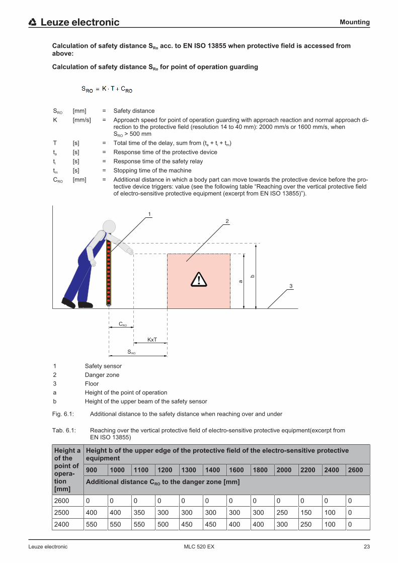
tective device triggers: value (see the following table “Reaching over the vertical protective fieldof electro-sensitive protective equipment (excerpt from EN ISO 13855)”).
a
3
CRO
KxT
b
1
2
SRO
1 Safety sensor2 Danger zone3 Floora Height of the point of operationb Height of the upper beam of the safety sensor
Fig. 6.1: Additional distance to the safety distance when reaching over and under
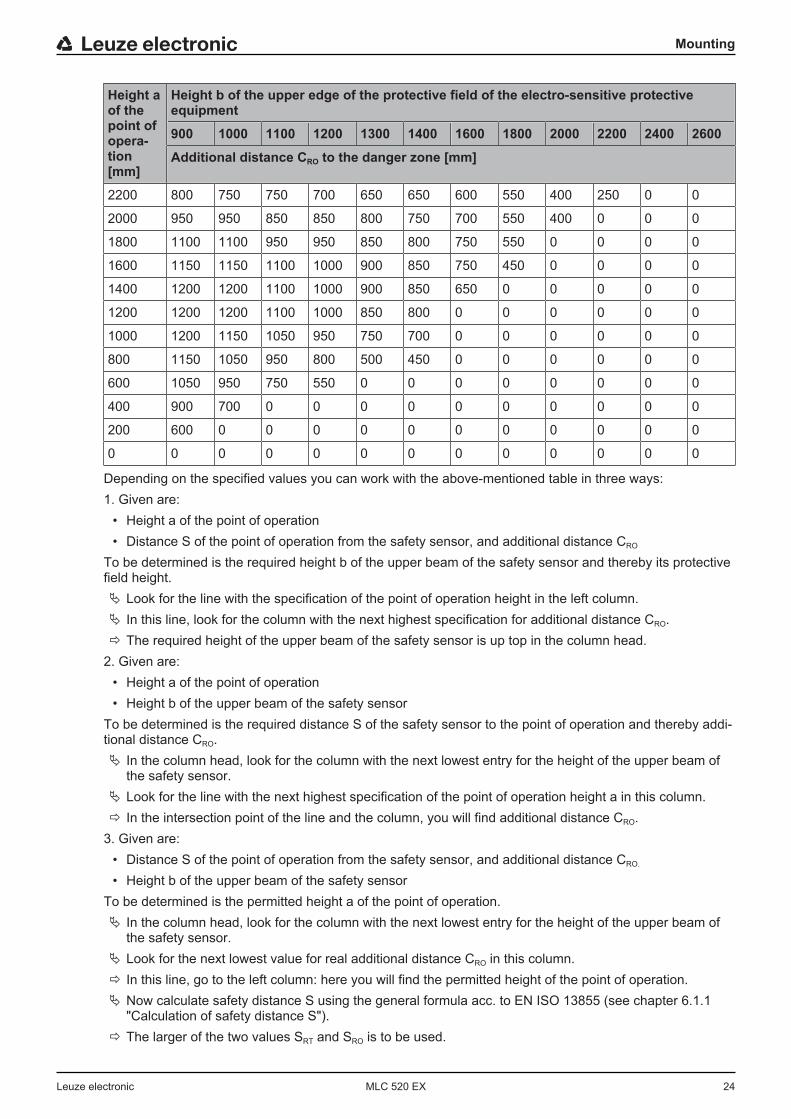
Tab. 6.1: Reaching over the vertical protective field of electro-sensitive protective equipment(excerpt fromEN ISO 13855)
Height aof thepoint ofopera-tion[mm]
Height b of the upper edge of the protective field of the electro-sensitive protectiveequipment
900 1000 1100 1200 1300 1400 1600 1800 2000 2200 2400 2600
Additional distance CRO to the danger zone [mm]
2600 0 0 0 0 0 0 0 0 0 0 0 0
2500 400 400 350 300 300 300 300 300 250 150 100 0
2400 550 550 550 500 450 450 400 400 300 250 100 0
Mounting
Leuze electronic MLC 520 EX 24
Height aof thepoint ofopera-tion[mm]
Height b of the upper edge of the protective field of the electro-sensitive protectiveequipment
900 1000 1100 1200 1300 1400 1600 1800 2000 2200 2400 2600
Additional distance CRO to the danger zone [mm]
2200 800 750 750 700 650 650 600 550 400 250 0 0
2000 950 950 850 850 800 750 700 550 400 0 0 0
1800 1100 1100 950 950 850 800 750 550 0 0 0 0
1600 1150 1150 1100 1000 900 850 750 450 0 0 0 0
1400 1200 1200 1100 1000 900 850 650 0 0 0 0 0
1200 1200 1200 1100 1000 850 800 0 0 0 0 0 0
1000 1200 1150 1050 950 750 700 0 0 0 0 0 0
800 1150 1050 950 800 500 450 0 0 0 0 0 0
600 1050 950 750 550 0 0 0 0 0 0 0 0
400 900 700 0 0 0 0 0 0 0 0 0 0
200 600 0 0 0 0 0 0 0 0 0 0 0
0 0 0 0 0 0 0 0 0 0 0 0 0
Depending on the specified values you can work with the above-mentioned table in three ways:1. Given are:
• Height a of the point of operation• Distance S of the point of operation from the safety sensor, and additional distance CRO
To be determined is the required height b of the upper beam of the safety sensor and thereby its protectivefield height.Ä Look for the line with the specification of the point of operation height in the left column.Ä In this line, look for the column with the next highest specification for additional distance CRO.ð The required height of the upper beam of the safety sensor is up top in the column head.
2. Given are:• Height a of the point of operation• Height b of the upper beam of the safety sensor
To be determined is the required distance S of the safety sensor to the point of operation and thereby addi-tional distance CRO.Ä In the column head, look for the column with the next lowest entry for the height of the upper beam of
the safety sensor.Ä Look for the line with the next highest specification of the point of operation height a in this column.ð In the intersection point of the line and the column, you will find additional distance CRO.
3. Given are:• Distance S of the point of operation from the safety sensor, and additional distance CRO.
• Height b of the upper beam of the safety sensorTo be determined is the permitted height a of the point of operation.Ä In the column head, look for the column with the next lowest entry for the height of the upper beam of
the safety sensor.Ä Look for the next lowest value for real additional distance CRO in this column.ð In this line, go to the left column: here you will find the permitted height of the point of operation.Ä Now calculate safety distance S using the general formula acc. to EN ISO 13855 (see chapter 6.1.1
"Calculation of safety distance S").ð The larger of the two values SRT and SRO is to be used.
Mounting
Leuze electronic MLC 520 EX 25
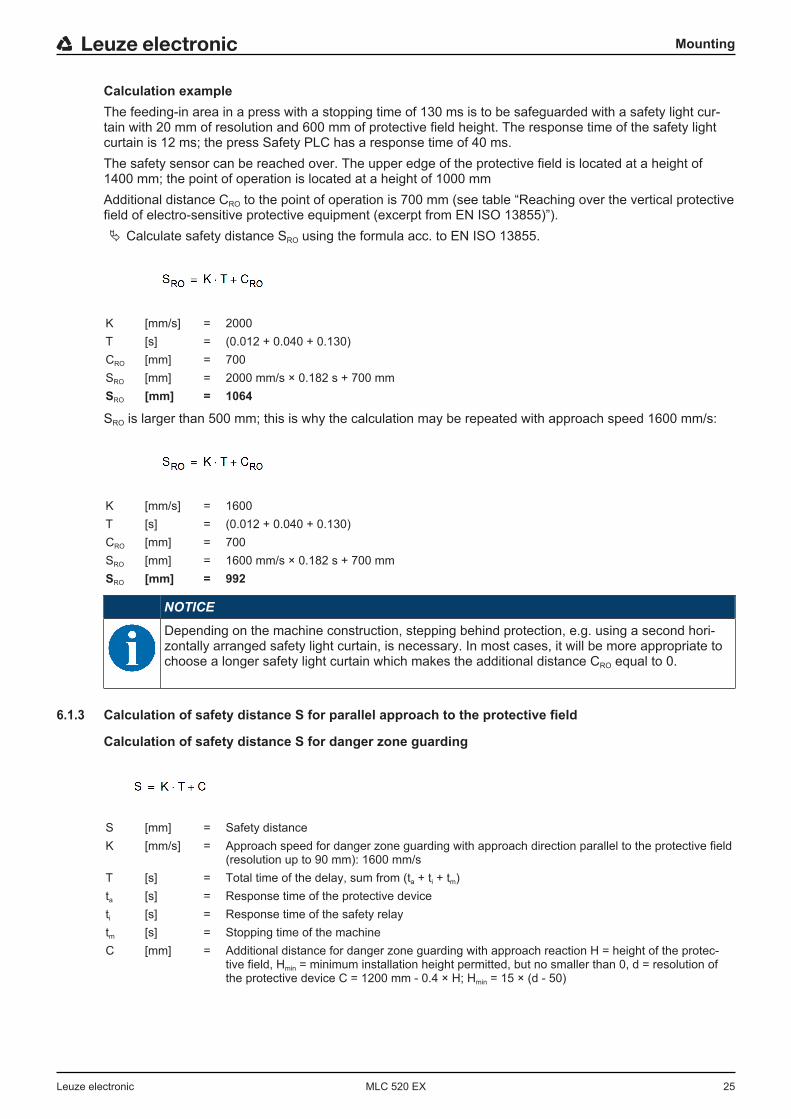
Calculation exampleThe feeding-in area in a press with a stopping time of 130 ms is to be safeguarded with a safety light cur-tain with 20 mm of resolution and 600 mm of protective field height. The response time of the safety lightcurtain is 12 ms; the press Safety PLC has a response time of 40 ms.The safety sensor can be reached over. The upper edge of the protective field is located at a height of1400 mm; the point of operation is located at a height of 1000 mmAdditional distance CRO to the point of operation is 700 mm (see table “Reaching over the vertical protectivefield of electro-sensitive protective equipment (excerpt from EN ISO 13855)”).Ä Calculate safety distance SRO using the formula acc. to EN ISO 13855.
K [mm/s] = 2000T [s] = (0.012 + 0.040 + 0.130)CRO [mm] = 700SRO [mm] = 2000 mm/s × 0.182 s + 700 mmSRO [mm] = 1064
SRO is larger than 500 mm; this is why the calculation may be repeated with approach speed 1600 mm/s:
K [mm/s] = 1600T [s] = (0.012 + 0.040 + 0.130)CRO [mm] = 700SRO [mm] = 1600 mm/s × 0.182 s + 700 mmSRO [mm] = 992
NOTICE
Depending on the machine construction, stepping behind protection, e.g. using a second hori-zontally arranged safety light curtain, is necessary. In most cases, it will be more appropriate tochoose a longer safety light curtain which makes the additional distance CRO equal to 0.
6.1.3 Calculation of safety distance S for parallel approach to the protective field
Calculation of safety distance S for danger zone guarding
S [mm] = Safety distanceK [mm/s] = Approach speed for danger zone guarding with approach direction parallel to the protective field
(resolution up to 90 mm): 1600 mm/sT [s] = Total time of the delay, sum from (ta + ti + tm)ta [s] = Response time of the protective deviceti [s] = Response time of the safety relaytm [s] = Stopping time of the machineC [mm] = Additional distance for danger zone guarding with approach reaction H = height of the protec-
tive field, Hmin = minimum installation height permitted, but no smaller than 0, d = resolution ofthe protective device C = 1200 mm - 0.4 × H; Hmin = 15 × (d - 50)

Mounting
Leuze electronic MLC 520 EX 26
Calculation exampleThe danger zone in front of a machine with a stopping time of 140 ms is to be safeguarded as close to thefloor height as possible using a horizontal safety light curtain as a replacement for a PS mat. Installationheight Hmin can be = 0 - additional distance C to the safety distance is then 1200 mm. The shortest possiblesafety sensor is to be used; the first value to be selected is to be 1350 mm.The receiver with 40 mm of resolution and 1350 mm protective field height has a response time of 13 ms,an additional relay interface a response time of 10 ms.Ä Calculate safety distance SRO using the formula acc. to EN ISO 13855.
K [mm/s] = 1600T [s] = (0.140 + 0.013 + 0.010)C [mm] = 1200S [mm] = 1600 mm/s × 0.163 s + 1200 mmS [mm] = 1461
The safety distance of 1350 mm is not sufficient; 1460 mm are necessary.This is why the calculation is repeated with a protective field height of 1500 mm. The response time is now14 ms.Ä Re-calculate safety distance SRO using the formula acc. to EN ISO 13855.
K [mm/s] = 1600T [s] = (0.140 + 0.014 + 0.010)C [mm] = 1200S [mm] = 1600 mm/s × 0.164 s + 1200 mmS [mm] = 1463
A suitable safety sensor has been found; its protective field height is 1500 mm.
Mounting
Leuze electronic MLC 520 EX 27
6.1.4 Minimum distance to reflective surfaces
WARNING
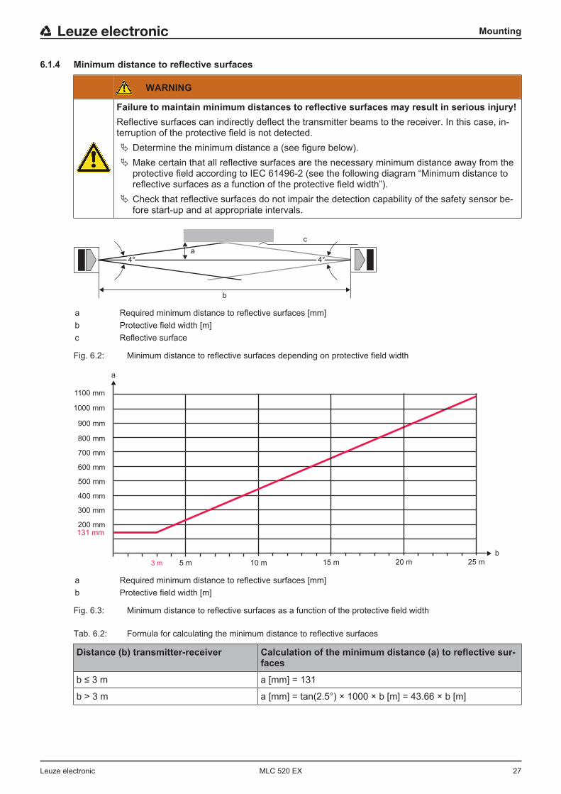
Failure to maintain minimum distances to reflective surfaces may result in serious injury!Reflective surfaces can indirectly deflect the transmitter beams to the receiver. In this case, in-terruption of the protective field is not detected.Ä Determine the minimum distance a (see figure below).Ä Make certain that all reflective surfaces are the necessary minimum distance away from the
protective field according to IEC 61496-2 (see the following diagram “Minimum distance toreflective surfaces as a function of the protective field width”).
Ä Check that reflective surfaces do not impair the detection capability of the safety sensor be-fore start-up and at appropriate intervals.
a
b
4° 4°
c
a Required minimum distance to reflective surfaces [mm]b Protective field width [m]c Reflective surface
Fig. 6.2: Minimum distance to reflective surfaces depending on protective field width
a
900 mm
200 mm
800 mm
300 mm
400 mm
600 mm
500 mm
700 mm
3 m 5 m 10 m
b
131 mm
15 m 20 m 25 m
1100 mm
1000 mm
a Required minimum distance to reflective surfaces [mm]b Protective field width [m]
Fig. 6.3: Minimum distance to reflective surfaces as a function of the protective field width
Tab. 6.2: Formula for calculating the minimum distance to reflective surfaces
Distance (b) transmitter-receiver Calculation of the minimum distance (a) to reflective sur-faces
b ≤ 3 m a [mm] = 131
b > 3 m a [mm] = tan(2.5°) × 1000 × b [m] = 43.66 × b [m]

Mounting
Leuze electronic MLC 520 EX 28
6.1.5 Preventing mutual interference between adjacent devicesIf a receiver is located in the beam path of an adjacent transmitter, optical crosstalk, and thus erroneousswitching and failure of the protective function, may result.
2 41 3
Fig. 6.4: Optical crosstalk between adjacent safety sensors (transmitter 1 influences receiver 2) due to incorrectmounting
1 Transmitter 12 Receiver 13 Transmitter 24 Receiver 2
NOTICE
Possible impairment of the availability due to systems mounted close to each other!The transmitter of one system can influence the receiver of the other system.Ä Prevent optical crosstalk between adjacent devices.
Ä Mount adjacent devices with a shield between them or install a dividing wall to prevent mutual interfer-ence.
Ä Mount the adjacent devices opposite from one another to prevent mutual interference.
2 41 3
Fig. 6.5: Opposite mounting
1 Receiver 12 Transmitter 13 Transmitter 2
Mounting
Leuze electronic MLC 520 EX 29
4 Receiver 2
In addition to design characteristics, the safety sensor offers functions that can remedy this:• Selectable transmission channels (see chapter 4.3 "Transmission channel changeover")• Range reduction (see chapter 4.4 "Range reduction")• Also: opposite mounting
6.2 Mounting the safety sensorProceed as follows:
• Select the type of fastening, e.g. sliding blocks (see chapter 6.2.3 "Fastening via BT-NC60 slidingblocks").
• Have a suitable tool at hand and mount the safety sensor in accordance with the notices regarding themounting locations (see chapter 6.2.1 "Suitable mounting locations").
• If possible, affix safety notice stickers on the mounted safety sensor or device column (included in de-livery contents).
After mounting, you can electrically connect (see chapter 7 "Electrical connection"), start up, align (seechapter 8 "Starting up the device"), and test (see chapter 9.1 "Before the initial start-up and following modi-fications") the safety sensor.
6.2.1 Suitable mounting locationsArea of application: MountingTester: Technician who mounts the safety sensor
Tab. 6.3: Checklist for mounting preparations
Check: Yes No
Do the protective field height and dimensions satisfy the requirements of EN 13855?
Is the safety distance to the point of operation maintained (see chapter 6.1.1 "Calculationof safety distance S")?
Is the minimum distance to reflective surfaces maintained (see chapter 6.1.4 "Minimumdistance to reflective surfaces")?
Is it impossible for safety sensors that are mounted next to one another to mutually inter-fere with one another (see chapter 6.1.5 "Preventing mutual interference between adjacentdevices")?
Can the point of operation or the danger zone only be accessed through the protectivefield?
Has bypassing the protective field by crawling under, reaching over, or jumping over beenprevented or has corresponding additional distance CRO in accordance with EN ISO 13855been observed?
Is stepping behind the protective device prevented or is mechanical protection available?
Do the transmitter and receiver connections point in the same direction?
Can the transmitter and receiver be fastened in such a way that they cannot be movedand turned?
Is the safety sensor accessible for testing and replacing?
Is it impossible to actuate the reset button from within the danger zone?
Can the entire danger zone be seen from the installation site of the reset button?
Can reflection caused by the installation site be ruled out?
Mounting
Leuze electronic MLC 520 EX 30
NOTICE
If you answer one of the items on the checklist above with no, the mounting location must bechanged.
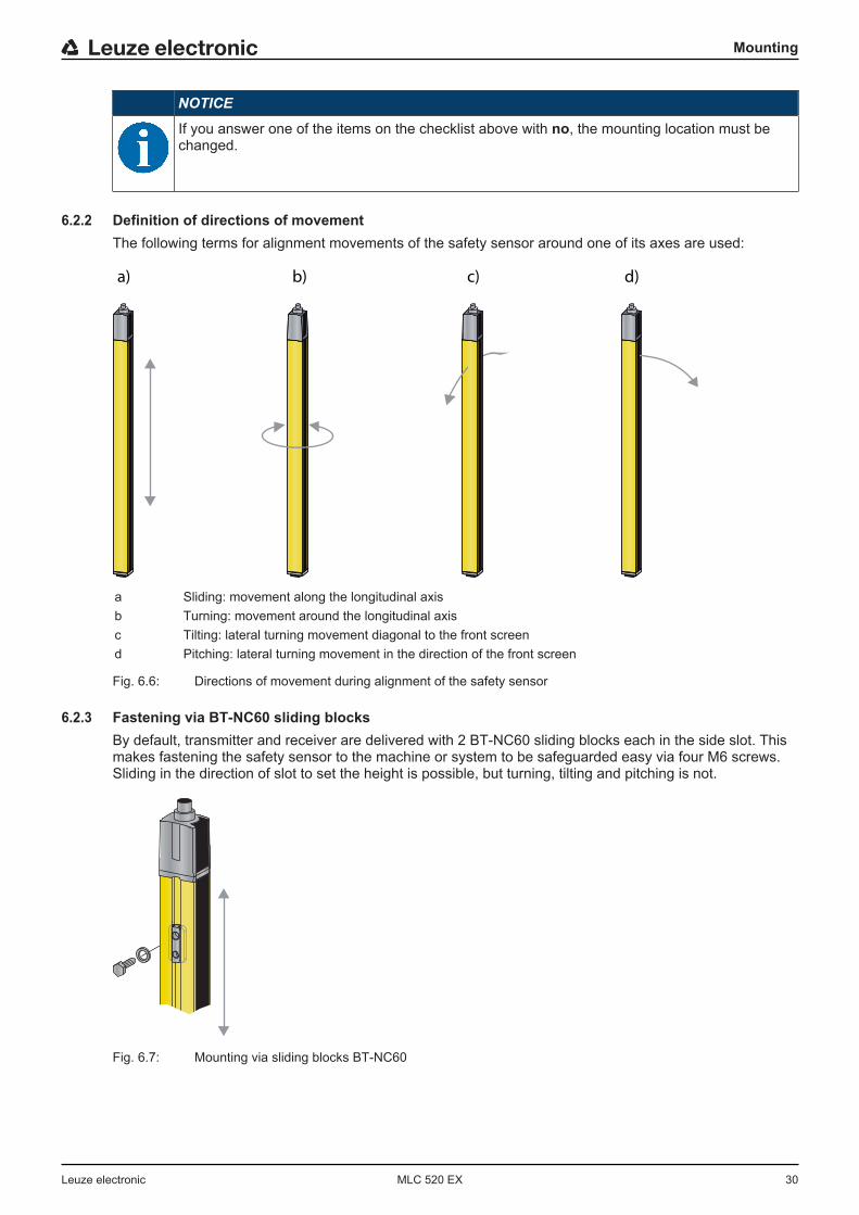
6.2.2 Definition of directions of movementThe following terms for alignment movements of the safety sensor around one of its axes are used:
a) b) c) d)
a Sliding: movement along the longitudinal axisb Turning: movement around the longitudinal axisc Tilting: lateral turning movement diagonal to the front screend Pitching: lateral turning movement in the direction of the front screen
Fig. 6.6: Directions of movement during alignment of the safety sensor
6.2.3 Fastening via BT-NC60 sliding blocksBy default, transmitter and receiver are delivered with 2 BT-NC60 sliding blocks each in the side slot. Thismakes fastening the safety sensor to the machine or system to be safeguarded easy via four M6 screws.Sliding in the direction of slot to set the height is possible, but turning, tilting and pitching is not.
Fig. 6.7: Mounting via sliding blocks BT-NC60
Mounting
Leuze electronic MLC 520 EX 31
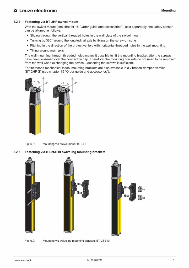
6.2.4 Fastening via BT-2HF swivel mountWith the swivel mount (see chapter 15 "Order guide and accessories"), sold separately, the safety sensorcan be aligned as follows:
• Sliding through the vertical threaded holes in the wall plate of the swivel mount• Turning by 360° around the longitudinal axis by fixing on the screw-on cone• Pitching in the direction of the protective field with horizontal threaded holes in the wall mounting• Tilting around main axis
The wall mounting through threaded holes makes it possible to lift the mounting bracket after the screwshave been loosened over the connection cap. Therefore, the mounting brackets do not need to be removedfrom the wall when exchanging the device. Loosening the screws is sufficient.For increased mechanical loads, mounting brackets are also available in a vibration-damped version(BT-2HF-S) (see chapter 15 "Order guide and accessories").
Fig. 6.8: Mounting via swivel mount BT-2HF
6.2.5 Fastening via BT-2SB10 swiveling mounting brackets
Fig. 6.9: Mounting via swiveling mounting brackets BT-2SB10
Mounting
Leuze electronic MLC 520 EX 32
For larger protective field heights > 900 mm, the use of the BT-2SB10 swiveling mounting brackets is rec-ommended (see chapter 15 "Order guide and accessories"). For increased mechanical requirements, theseare also available as vibration-damped version (BT-2SB10-S). Depending on the installation situation, envi-ronmental conditions and protective field length (> 1200 mm), other mounting brackets may also be neces-sary.
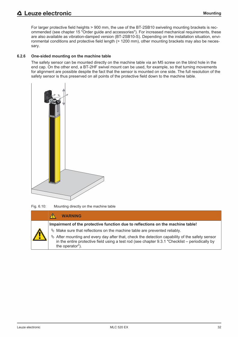
6.2.6 One-sided mounting on the machine tableThe safety sensor can be mounted directly on the machine table via an M5 screw on the blind hole in theend cap. On the other end, a BT-2HF swivel mount can be used, for example, so that turning movementsfor alignment are possible despite the fact that the sensor is mounted on one side. The full resolution of thesafety sensor is thus preserved on all points of the protective field down to the machine table.
Fig. 6.10: Mounting directly on the machine table
WARNING
Impairment of the protective function due to reflections on the machine table!Ä Make sure that reflections on the machine table are prevented reliably.Ä After mounting and every day after that, check the detection capability of the safety sensor
in the entire protective field using a test rod (see chapter 9.3.1 "Checklist – periodically bythe operator").

Mounting
Leuze electronic MLC 520 EX 33
6.3 Mounting accessories
6.3.1 Deflecting mirror for multiple-side guardingFor multiple-side guarding, redirecting the protective field with one or two deflecting mirrors is economical.To do this, Leuze electronic supplies:
• The UM60 deflecting mirror for mounting on the machine in various lengths (see chapter 15 "Orderguide and accessories")
• suitable BT-2UM60 swivel mounts• UMC-1000-S2 … UMC-1900-S2 deflecting mirror columns with spring-damped base for free-standing
floor mountingThe range is reduced by approx. 10 % per deflection. A laser alignment aid with red light laser is recom-mended for the alignment of transmitter and receiver (see chapter 8.3 "Aligning of deflecting mirrors withthe laser alignment aid").Ä Note that the distance between the transmitter and the first deflecting mirror cannot be larger than 3 m.
2
1
3
1 Transmitter2 Receiver3 UM60 deflecting mirrors
Fig. 6.11: Arrangement with deflecting mirror for 2-side guarding of a point of operation
Mounting
Leuze electronic MLC 520 EX 34
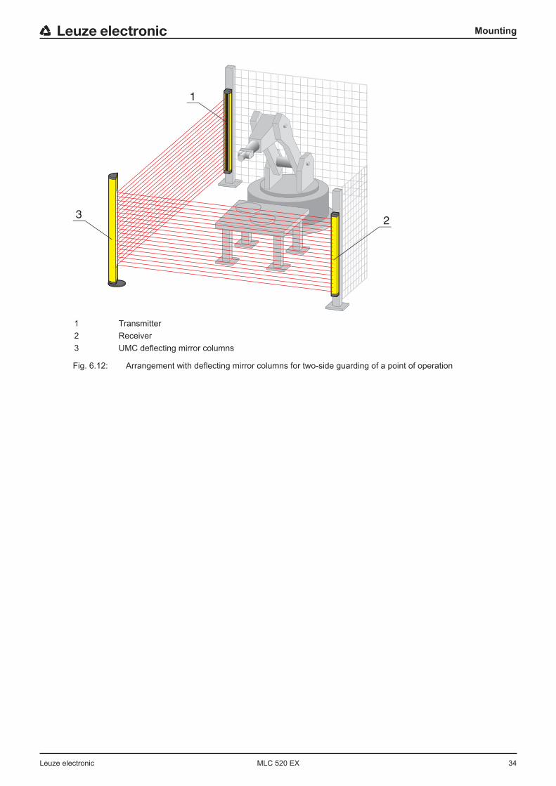
2
1
3
1 Transmitter2 Receiver3 UMC deflecting mirror columns
Fig. 6.12: Arrangement with deflecting mirror columns for two-side guarding of a point of operation
Electrical connection
Leuze electronic MLC 520 EX 35
7 Electrical connection
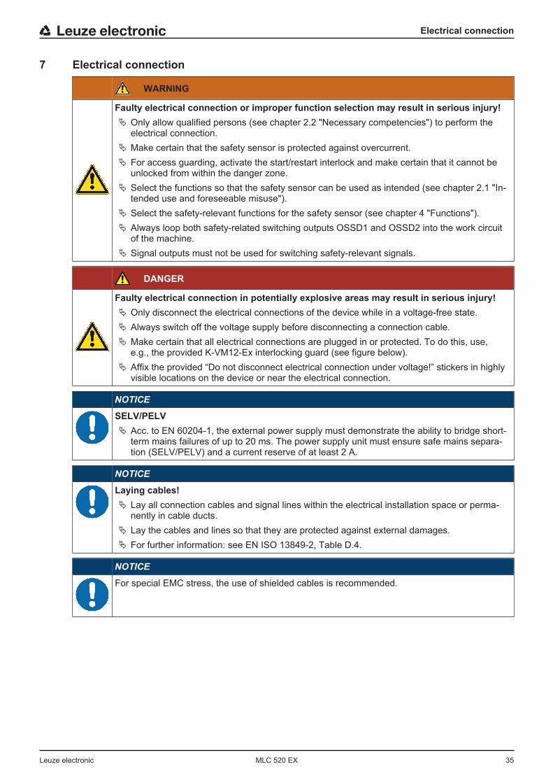
WARNING
Faulty electrical connection or improper function selection may result in serious injury!Ä Only allow qualified persons (see chapter 2.2 "Necessary competencies") to perform the
electrical connection.Ä Make certain that the safety sensor is protected against overcurrent.Ä For access guarding, activate the start/restart interlock and make certain that it cannot be
unlocked from within the danger zone.Ä Select the functions so that the safety sensor can be used as intended (see chapter 2.1 "In-
tended use and foreseeable misuse").Ä Select the safety-relevant functions for the safety sensor (see chapter 4 "Functions").Ä Always loop both safety-related switching outputs OSSD1 and OSSD2 into the work circuit
of the machine.Ä Signal outputs must not be used for switching safety-relevant signals.
DANGER
Faulty electrical connection in potentially explosive areas may result in serious injury!Ä Only disconnect the electrical connections of the device while in a voltage-free state.Ä Always switch off the voltage supply before disconnecting a connection cable.Ä Make certain that all electrical connections are plugged in or protected. To do this, use,
e.g., the provided K-VM12-Ex interlocking guard (see figure below).Ä Affix the provided “Do not disconnect electrical connection under voltage!” stickers in highly
visible locations on the device or near the electrical connection.
NOTICE
SELV/PELVÄ Acc. to EN 60204-1, the external power supply must demonstrate the ability to bridge short-
term mains failures of up to 20 ms. The power supply unit must ensure safe mains separa-tion (SELV/PELV) and a current reserve of at least 2 A.
NOTICE
Laying cables!Ä Lay all connection cables and signal lines within the electrical installation space or perma-
nently in cable ducts.Ä Lay the cables and lines so that they are protected against external damages.Ä For further information: see EN ISO 13849-2, Table D.4.
NOTICE
For special EMC stress, the use of shielded cables is recommended.

Electrical connection
Leuze electronic MLC 520 EX 36
Fig. 7.1: K-VM12-Ex interlocking guard
7.1 Pin assignment transmitter and receiver
7.1.1 MLC 500 transmitterMLC 500 transmitters are equipped with a 5-pin M12 connector.
2
3
1
4
5
FE
VIN1
1
RNG
4
VIN2
3
FE
5
-A1
MLCx00T
n.c.
2
Fig. 7.2: Pin assignment and connection diagram transmitter
Tab. 7.1: Pin assignment transmitter
Pin Core color (CB-M12-xx000E-5GF) Transmitter
1 Brown VIN1 - supply voltage
2 White n.c.
3 Blue VIN2 - supply voltage
4 Black RNG - range
5 Gray FE - functional earth, shield
FE FE - functional earth, shield
The polarity of the supply voltage selects the transmission channel of the transmitter:• VIN1 = +24 V, VIN2 = 0 V: transmission channel C1• VIN1 = 0 V, VIN2 = +24 V: transmission channel C2
The wiring of pin 4 determines the transmitting power and thereby the range:• Pin 4 = +24 V: standard range• Pin 4 = 0 V or open: reduced range
Electrical connection
Leuze electronic MLC 520 EX 37
VIN1
1
RNG
4
VIN2
3
FE
5
-A1
MLCx00T
n.c.
2
+ 24V
FE
0V
+ 24V
FE
0V
1
WH
GY
BU
BN
BK
VIN1
1
RNG
4
VIN2
3
FE
5
-A1
MLCx00T
+ 24V
FE
0V
+ 24V
FE
0V
2
n.c.
2
WH
GY
BU
BN
BK
VIN2
3
RNG
4
VIN1
1
FE
5
-A1
MLCx00T
+ 24V
FE
0V
+ 24V
FE
0V
3
n.c.
2
WH
GY
BN
BU
BK
VIN2
3
RNG
4
VIN1
1
FE
5
-A1
MLCx00T
+ 24V
FE
0V
+ 24V
FE
0V
4
n.c.
2
WH
GY
BN
BU
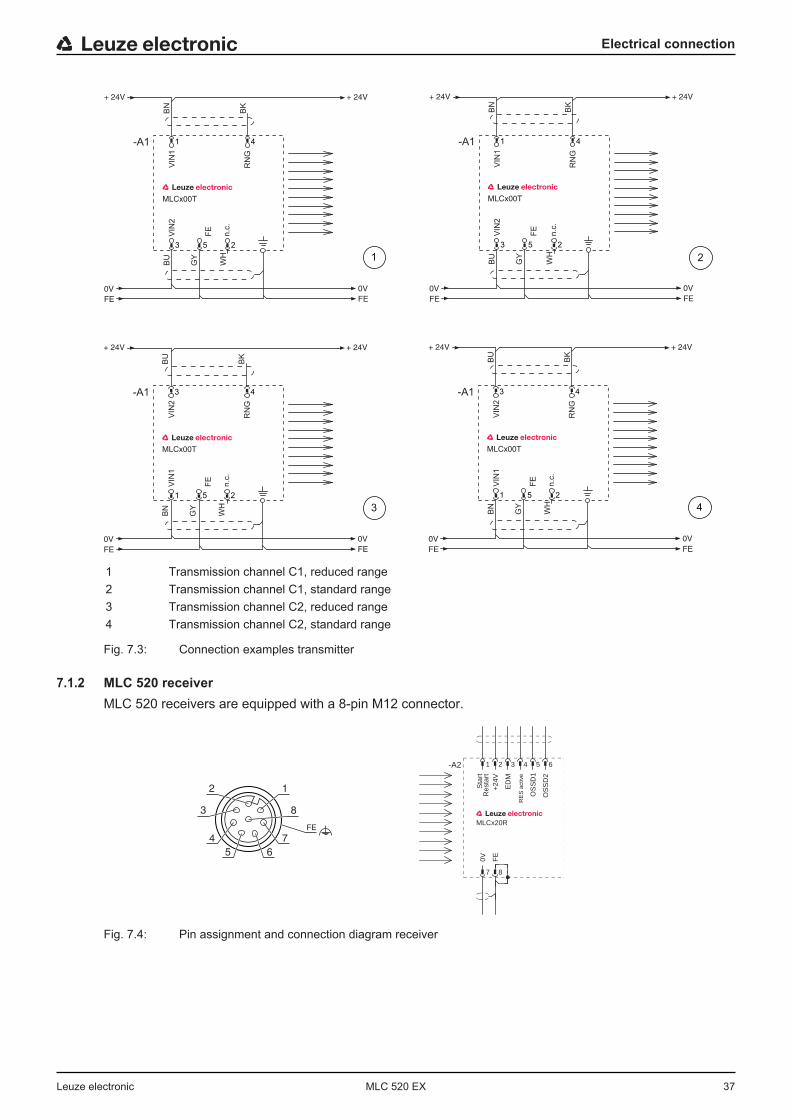
BK
1 Transmission channel C1, reduced range2 Transmission channel C1, standard range3 Transmission channel C2, reduced range4 Transmission channel C2, standard range
Fig. 7.3: Connection examples transmitter
7.1.2 MLC 520 receiverMLC 520 receivers are equipped with a 8-pin M12 connector.
3
4
1
7
8
FE
2
65
ED
M
OS
SD
1
OS
SD
2
Sta
rt
MLCx20R
Res
tart
0V FE
+24
V
8
643 5
7
21-A2
RE
S a
ctiv
e
Fig. 7.4: Pin assignment and connection diagram receiver
Electrical connection
Leuze electronic MLC 520 EX 38
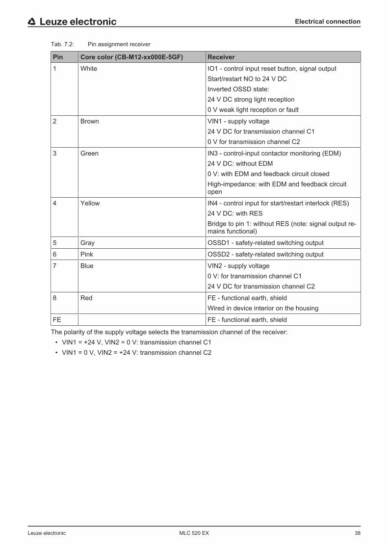
Tab. 7.2: Pin assignment receiver
Pin Core color (CB-M12-xx000E-5GF) Receiver
1 White IO1 - control input reset button, signal outputStart/restart NO to 24 V DCInverted OSSD state:24 V DC strong light reception0 V weak light reception or fault
2 Brown VIN1 - supply voltage24 V DC for transmission channel C10 V for transmission channel C2
3 Green IN3 - control-input contactor monitoring (EDM)24 V DC: without EDM0 V: with EDM and feedback circuit closedHigh-impedance: with EDM and feedback circuitopen
4 Yellow IN4 - control input for start/restart interlock (RES)24 V DC: with RESBridge to pin 1: without RES (note: signal output re-mains functional)
5 Gray OSSD1 - safety-related switching output
6 Pink OSSD2 - safety-related switching output
7 Blue VIN2 - supply voltage0 V: for transmission channel C124 V DC for transmission channel C2
8 Red FE - functional earth, shieldWired in device interior on the housing
FE FE - functional earth, shield
The polarity of the supply voltage selects the transmission channel of the receiver:• VIN1 = +24 V, VIN2 = 0 V: transmission channel C1• VIN1 = 0 V, VIN2 = +24 V: transmission channel C2
Electrical connection
Leuze electronic MLC 520 EX 39
7.2 Circuit diagram examples
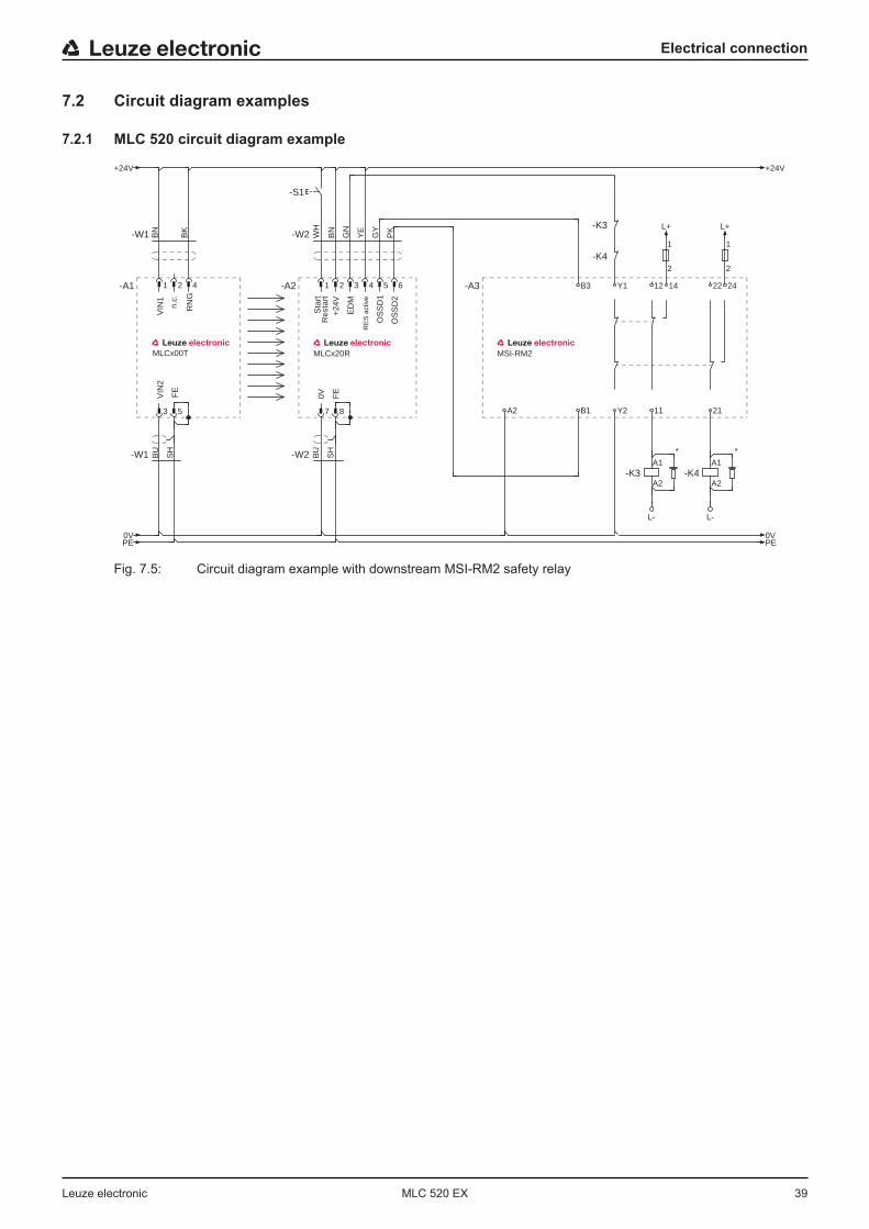
7.2.1 MLC 520 circuit diagram example
ED
M
OS
SD
1
MSI-RM2
OS
SD
2
Sta
rt
MLCx20R
Res
tart
0V FE
+24
V
WH
A1
A2-K3
A1
A2-K4
PK
GN
1
2
1
2
BU
SH
8
-W1 BU
SH-W2
-S1
A25
14B36 Y1
BN
B1
4 -A3
11
3 12 22
YE
-K4
-K3
21Y2
-W1 BK
BN
5
-W2
7
21-A24
3
21-A1 24
GY
PE
+24V
0V
+24V
PE0V
L+L+
L- L-
RE
S a
ctiv
e
* *
VIN
1
RN
G
MLCx00T
FE
VIN
2
n.c.
Fig. 7.5: Circuit diagram example with downstream MSI-RM2 safety relay
Starting up the device
Leuze electronic MLC 520 EX 40
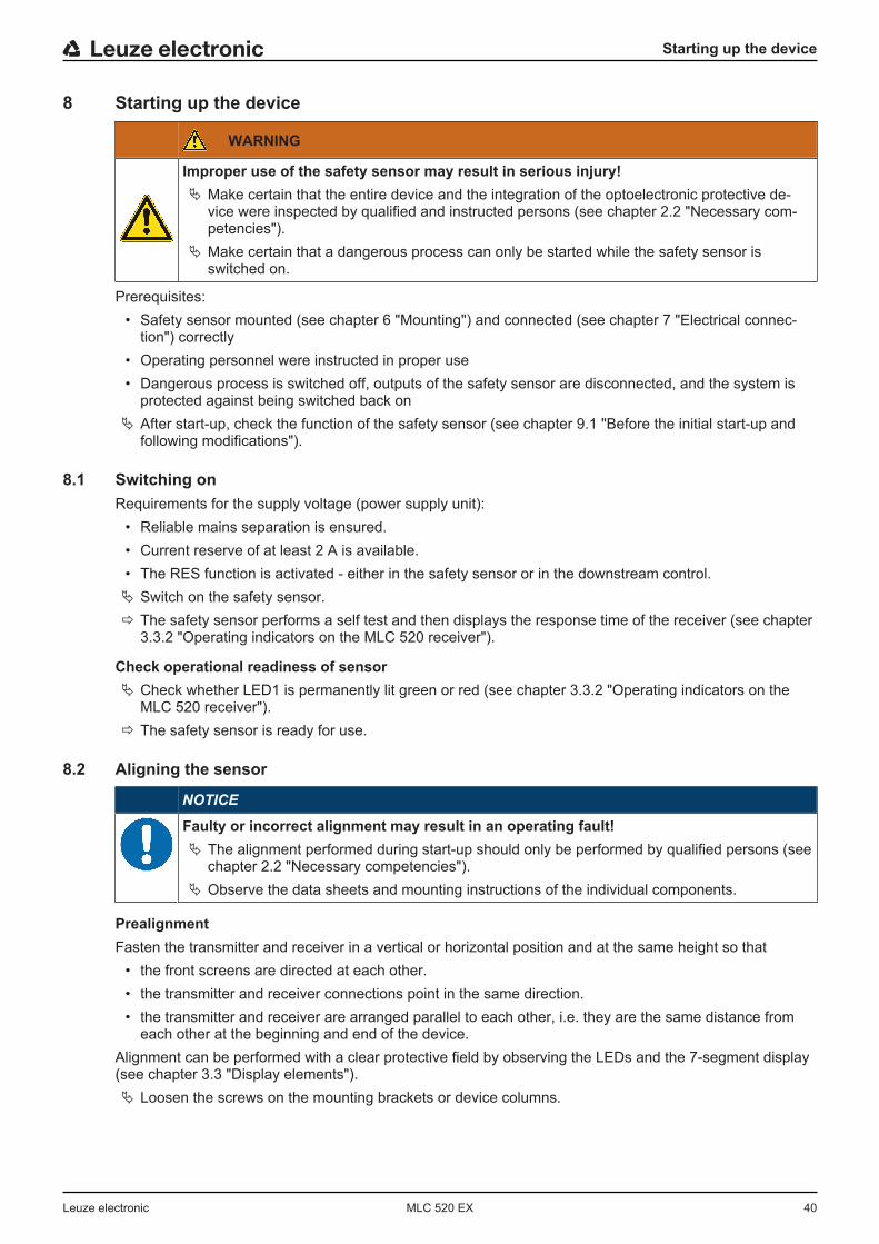
8 Starting up the device
WARNING
Improper use of the safety sensor may result in serious injury!Ä Make certain that the entire device and the integration of the optoelectronic protective de-
vice were inspected by qualified and instructed persons (see chapter 2.2 "Necessary com-petencies").
Ä Make certain that a dangerous process can only be started while the safety sensor isswitched on.
Prerequisites:• Safety sensor mounted (see chapter 6 "Mounting") and connected (see chapter 7 "Electrical connec-
tion") correctly• Operating personnel were instructed in proper use• Dangerous process is switched off, outputs of the safety sensor are disconnected, and the system is
protected against being switched back onÄ After start-up, check the function of the safety sensor (see chapter 9.1 "Before the initial start-up and
following modifications").
8.1 Switching onRequirements for the supply voltage (power supply unit):
• Reliable mains separation is ensured.• Current reserve of at least 2 A is available.• The RES function is activated - either in the safety sensor or in the downstream control.Ä Switch on the safety sensor.ð The safety sensor performs a self test and then displays the response time of the receiver (see chapter
3.3.2 "Operating indicators on the MLC 520 receiver").
Check operational readiness of sensorÄ Check whether LED1 is permanently lit green or red (see chapter 3.3.2 "Operating indicators on the
MLC 520 receiver").ð The safety sensor is ready for use.
8.2 Aligning the sensor
NOTICE
Faulty or incorrect alignment may result in an operating fault!Ä The alignment performed during start-up should only be performed by qualified persons (see
chapter 2.2 "Necessary competencies").Ä Observe the data sheets and mounting instructions of the individual components.
PrealignmentFasten the transmitter and receiver in a vertical or horizontal position and at the same height so that
• the front screens are directed at each other.• the transmitter and receiver connections point in the same direction.• the transmitter and receiver are arranged parallel to each other, i.e. they are the same distance from
each other at the beginning and end of the device.Alignment can be performed with a clear protective field by observing the LEDs and the 7-segment display(see chapter 3.3 "Display elements").Ä Loosen the screws on the mounting brackets or device columns.
Starting up the device
Leuze electronic MLC 520 EX 41
NOTICE
Loosen the screws only enough so that the devices can just be moved.
Ä Turn the receiver to the left until LED1 still flashes green but does not yet illuminate red. If necessary,you may have to turn the transmitter beforehand.ð The receiver with activated alignment display shows flashing segments in the 7-segment display.
Ä Note the value of the twist angle.Ä Turn the receiver to the right until LED1 still flashes green but does not yet illuminate red.Ä Note the value of the twist angle.Ä Set the optimum position of the receiver. This lies in the middle of the two values for the twist angle to
the left and right.Ä Tighten the fastening screws of the receiver.Ä Now align the transmitter according to the same method, paying attention to the display elements of the
receiver while doing so (see chapter 3.3.2 "Operating indicators on the MLC 520 receiver").
NOTICE
Separate alignment aids such as the AC-ALM are also available as accessories.
8.3 Aligning of deflecting mirrors with the laser alignment aidWhen using deflecting mirrors for multiple-side point of operation guarding and access guarding, an exter-nal laser alignment aid is recommended (see chapter 15 "Order guide and accessories").
NOTICE
With its clearly visible red light spot, the external laser alignment aid facilitates the correct set-ting of the transmitter and receiver as well as the deflecting mirrors.
Ä Fasten the laser alignment aid on top on the side groove of the transmitter. Mounting instructions areincluded in the accessories.
Ä Switch on the laser. Take note of the operating instructions of the laser alignment aid concerning thesafety notices and the activation of the laser alignment aid.
Ä Loosen the mounting bracket of the transmitter and turn or tilt or pitch the device so that the laser spotstrikes the top of the first deflecting mirror (see chapter 6.2.2 "Definition of directions of movement").
Ä Now set the laser below on the transmitter and adjust it so that the laser spot strikes the bottom of thedeflecting mirror.
Ä Now set the laser back up top on the transmitter and check if the laser spot still strikes the top of thedeflecting mirror. If it does not, the mounting height of the transmitter must be changed, if applicable.
Ä Repeat the process until the laser strikes the respective point of the deflecting mirror, both on top andon bottom.
Ä Turn, tilt or pitch the deflecting mirror so that the laser spot strikes either the next deflecting mirror orthe receiver in both positions.
Ä Repeat the process in reverse after setting the laser alignment aid above and below on the receiver.The laser beam must strike the transmitter in both cases if the receiver has been correctly aligned.
Ä Remove the laser alignment aid from the safety sensor.ð The protective field is free. LED1 on the receiver is permanently lit green. The OSSDs switch on.

Starting up the device
Leuze electronic MLC 520 EX 42
8.4 Unlocking start/restart interlockThe reset button can be used to unlock the start/restart interlock. In this way, the responsible person canrestore the ON state of the safety sensor following process interruptions (due to triggering of protectivefunction, failure of the voltage supply).
WARNING
Premature unlocking of the start/restart interlock may result in serious injury!If the start/restart interlock is unlocked, the system can start up automatically.Ä Before unlocking the start/restart interlock, make certain that no people are in the danger
zone.
The red LED of the receiver illuminates as long as the restart is locked (OSSDs off). The yellow LED illumi-nates when the protective field is free and RES is activated (ready to be unlocked).Ä Make certain that the active protective field is clear.Ä Make certain that there are no people in the danger zone.Ä Press and release the reset button within 0.15 to 4 s. The receiver switches to the ON state.
If you keep the reset button pressed longer than 4 s:• Starting at 4 s: the reset request is ignored.• Starting at 30 s: a +24 V short circuit is assumed on the reset input and the receiver switches to the in-
terlock state (see chapter 11.1 "What to do in case of failure?").
Testing
Leuze electronic MLC 520 EX 43
9 TestingNOTICE
Ä Safety sensors must be replaced at the end of their mission time (see chapter 14 "Technicaldata").
Ä Always exchange entire safety sensors.Ä Observe any nationally applicable regulations regarding the tests.Ä Document all tests in a comprehensible manner and include the configuration of the safety
sensor along with the data for the safety- and minimum distances in the documentation.
9.1 Before the initial start-up and following modifications
WARNING
Unpredictable machine behavior during initial start-up may result in serious injury!Ä Make certain that there are no people in the danger zone.
Ä Before they begin work, train the operators on their respective tasks. The training is the responsibility ofthe operating company.
Ä Attach notes regarding daily testing in the respective national language of the operator on the machinein a highly visible location, e.g. by printing out the corresponding chapter (see chapter 9.3 "Periodicallyby the operator").
Ä Test the electrical function and installation according to this document.Acc. to IEC/TS 62046 and national regulations (e.g. EU directive 2009/104/EC), tests are to be performedby qualified persons (see chapter 2.2 "Necessary competencies") in the following situations:
• Prior to initial commissioning• Following modifications to the machine• After longer machine downtime• Following retrofitting or new configuration of the machineÄ As preparation, check the most important criteria for the safety sensor according to the following check-
list (see chapter 9.1.1 "Checklist for integrator – to be performed prior to the initial start-up and followingmodifications"). Completing the checklist does not replace testing by a qualified person (see chapter2.2 "Necessary competencies")!
ð Not until proper function of the safety sensor is ascertained may it be integrated in the control circuit ofthe system.
9.1.1 Checklist for integrator – to be performed prior to the initial start-up and following modifications
NOTICE
Completing the checklist does not replace testing by a qualified person (see chapter 2.2"Necessary competencies")!Ä If you answer one of the items on the following check list with no, the machine must no
longer be operated.Ä IEC/TS 62046 contains additional recommendations on testing protective devices
Tab. 9.1: Checklist for integrator – to be performed prior to the initial start-up and following modifications
Check: Yes No not ap-plicable
Is the safety sensor operated acc. to the specific environmental condi-tions that are to be maintained (see chapter 14 "Technical data")?
Is the safety sensor correctly aligned and are all fastening screws andconnectors secure?

Testing
Leuze electronic MLC 520 EX 44
Check: Yes No not ap-plicable
Are safety sensor, connection cables, connectors, protection caps andcommand devices undamaged and without any sign of manipulation?
Does the safety sensor satisfy the required safety level (PL, SIL, cate-gory)?
Are both safety-related switching outputs (OSSDs) integrated in thedownstream machine control acc. to the required safety category?
Are switching elements that are controlled by the safety sensor moni-tored according to the required safety level (PL, SIL, category) (e.g.,contactors through EDM)?
Are all points of operation near the safety sensor accessible onlythrough the protective field of the safety sensor?
Are the necessary additional protective devices in the immediate sur-roundings (e.g., safety guard) properly mounted and secured againsttampering?
If it is possible to be present undetected between the safety sensor andpoint of operation: is an assigned start/restart interlock functional?
Is the command device for unlocking the start/restart interlock mountedin such a way that it cannot be reached from within the danger zoneand so that the complete danger zone can be seen from the installationlocation?
Has the maximum stopping time of the machine been measured anddocumented?
Is the required safety distance maintained?
Does interruption with a test object intended for this purpose cause thedangerous movement(s) to stop?
Is the safety sensor effective during the entire dangerous move-ment(s)?
Is the safety sensor effective in all relevant operating modes of the ma-chine?
Is start-up of dangerous movements reliably prevented if an active lightbeam or the protective field is interrupted with a test object intended forthis purpose?
Was the sensor detection capacity successfully tested (see chapter9.3.1 "Checklist – periodically by the operator")?
Were distances to reflective surfaces taken into account during config-uration and no reflection bypasses subsequently detected?
Are notices for regular testing of the safety sensor legible to the opera-tor and are they located in a highly visible location?
Are changes to the safety function (e.g.: SPG, blanking, protective fieldswitchover) not easy to achieve through tampering?
Are settings that could result in an unsafe state possible only by meansof key, password or tool?
Are there incentives that pose stimulus for tampering?
Were the operators instructed prior to starting work?
Testing
Leuze electronic MLC 520 EX 45
9.2 Regularly by qualified personsThe reliable interaction of safety sensor and machine must be regularly tested by qualified persons (seechapter 2.2 "Necessary competencies") in order to detect changes to the machine or impermissible tamper-ing with the safety sensor.Acc. to IEC/TS 62046 and national regulations (e.g., EU directive 2009/104/EC), tests of elements whichare subject to wear must be performed by qualified persons (see chapter 2.2 "Necessary competencies") atregular intervals. Testing intervals may be regulated by nationally applicable regulations (recommendationacc. to IEC/TS 62046: 6 months).Ä Only allow testing to be performed by qualified persons (see chapter 2.2 "Necessary competencies").Ä Observe the nationally applicable regulations and the time periods specified therein.Ä As preparation, observe the checklist (see chapter 9.1 "Before the initial start-up and following modifi-
cations").
9.3 Periodically by the operatorThe function of the safety sensor must be checked depending on the given risk according to the followingchecklist so that damages or prohibited tampering can be detected.Depending on the risk assessment, the test cycle must be defined by the integrator or operating company(e.g., daily, on shift changes, ...) or is specified by national regulations or regulations of the employer's lia-bility insurance association and may be dependent on the machine type.Due to complex machines and processes, it may be necessary under certain circumstances to check somepoints at longer time intervals. Observe the classification in “Test at least” and “Test when possible”.
NOTICE
For larger distances between transmitter and receiver and when using deflecting mirrors, a sec-ond person may be necessary.
WARNING
Unpredictable machine behavior during the test may result in serious injury!Ä Make certain that there are no people in the danger zone.Ä Before they begin work, train the operators on their respective tasks and provide suitable
test objects and an appropriate test instruction.

Testing
Leuze electronic MLC 520 EX 46
9.3.1 Checklist – periodically by the operator
NOTICE
Ä If you answer one of the items on the following check list with no, the machine must nolonger be operated.
Tab. 9.2: Checklist – regular function test by trained operators/persons
Test at least: Yes No
Are safety sensor and connectors securely mounted and free of obvious signs of damage,changes or tampering?
Were no obvious changes made to access or entry possibilities?
Test the effectiveness of the safety sensor:• The LED 1 on the safety sensor must illuminate green (see chapter 3.3.2 "Operating
indicators on the MLC 520 receiver").• Interrupt an active beam or the protective field (see figure) with a suitable, opaque test
object:
Checking the protective field function with test rod (only for safety light curtains with a res-olution of 14 … 40 mm). For light curtains with different resolution ranges, this check is to
be performed separately for each resolution range in an analogous way.• Does the OSSD LED on the receiver illuminate constantly red while the protective field
is interrupted?
When possible, test during running operation: Yes No
Protective device with approach function: during machine operation, the protective field isinterrupted with the test object – are the obviously dangerous machine parts stopped with-out noticeable delay?
Protective device with presence detection: the protective field is interrupted with the testobject – does this prevent operation of the obviously dangerous machine parts?
Maintenance
Leuze electronic MLC 520 EX 47
10 MaintenanceNOTICE
Faulty operation if transmitter and receiver are soiled!The surfaces of the front screen of transmitters, receivers and, where applicable, deflecting mir-ror must not be scratched or roughened at the positions where beams enter and exit.Ä Do not use chemical cleaners.
Prerequisites for cleaning:• The system is safely shut down and protected against restart.Ä Clean the safety sensor periodically depending on the degree of contamination.
NOTICE
Prevent electrostatic charging of the front screens!Ä To clean the front screens of transmitter and receiver, use only damp cloths.
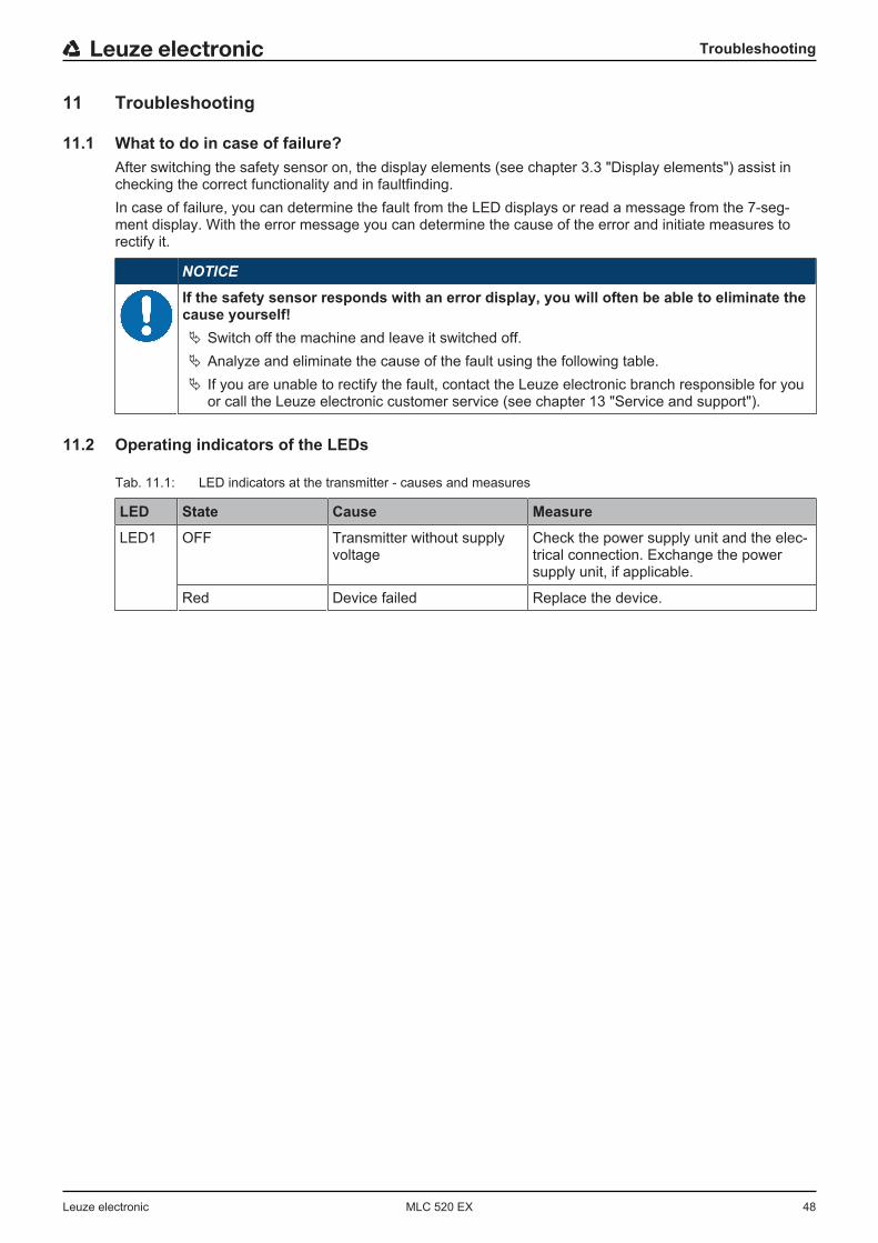
Troubleshooting
Leuze electronic MLC 520 EX 48
11 Troubleshooting
11.1 What to do in case of failure?After switching the safety sensor on, the display elements (see chapter 3.3 "Display elements") assist inchecking the correct functionality and in faultfinding.In case of failure, you can determine the fault from the LED displays or read a message from the 7-seg-ment display. With the error message you can determine the cause of the error and initiate measures torectify it.
NOTICE
If the safety sensor responds with an error display, you will often be able to eliminate thecause yourself!Ä Switch off the machine and leave it switched off.Ä Analyze and eliminate the cause of the fault using the following table.Ä If you are unable to rectify the fault, contact the Leuze electronic branch responsible for you
or call the Leuze electronic customer service (see chapter 13 "Service and support").
11.2 Operating indicators of the LEDs
Tab. 11.1: LED indicators at the transmitter - causes and measures
LED State Cause Measure
LED1 OFF Transmitter without supplyvoltage
Check the power supply unit and the elec-trical connection. Exchange the powersupply unit, if applicable.
Red Device failed Replace the device.
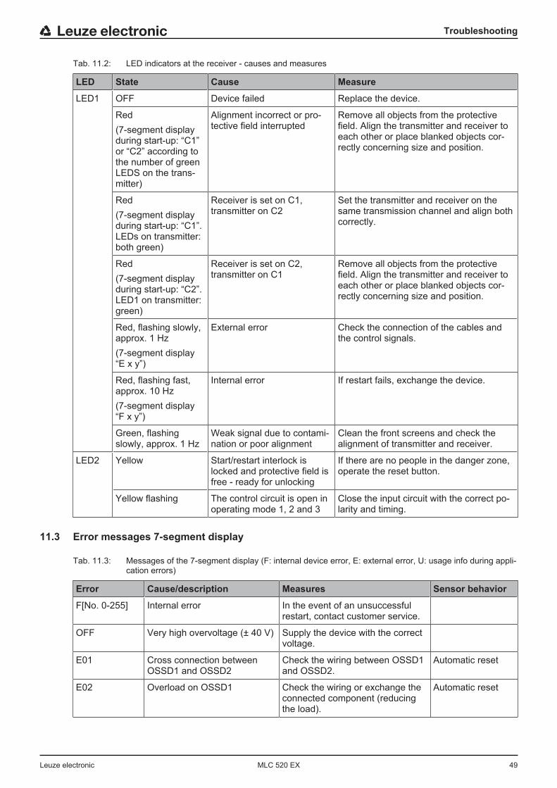
Troubleshooting
Leuze electronic MLC 520 EX 49
Tab. 11.2: LED indicators at the receiver - causes and measures
LED State Cause Measure
LED1 OFF Device failed Replace the device.
Red(7-segment displayduring start-up: “C1”or “C2” according tothe number of greenLEDS on the trans-mitter)
Alignment incorrect or pro-tective field interrupted
Remove all objects from the protectivefield. Align the transmitter and receiver toeach other or place blanked objects cor-rectly concerning size and position.
Red(7-segment displayduring start-up: “C1”.LEDs on transmitter:both green)
Receiver is set on C1, transmitter on C2
Set the transmitter and receiver on thesame transmission channel and align bothcorrectly.
Red(7-segment displayduring start-up: “C2”.LED1 on transmitter:green)
Receiver is set on C2, transmitter on C1
Remove all objects from the protectivefield. Align the transmitter and receiver toeach other or place blanked objects cor-rectly concerning size and position.
Red, flashing slowly,approx. 1 Hz(7-segment display“E x y”)
External error Check the connection of the cables andthe control signals.
Red, flashing fast,approx. 10 Hz(7-segment display“F x y”)
Internal error If restart fails, exchange the device.
Green, flashingslowly, approx. 1 Hz
Weak signal due to contami-nation or poor alignment
Clean the front screens and check thealignment of transmitter and receiver.
LED2 Yellow Start/restart interlock islocked and protective field isfree - ready for unlocking
If there are no people in the danger zone,operate the reset button.
Yellow flashing The control circuit is open inoperating mode 1, 2 and 3
Close the input circuit with the correct po-larity and timing.
11.3 Error messages 7-segment display
Tab. 11.3: Messages of the 7-segment display (F: internal device error, E: external error, U: usage info during appli-cation errors)
Error Cause/description Measures Sensor behavior
F[No. 0-255] Internal error In the event of an unsuccessfulrestart, contact customer service.
OFF Very high overvoltage (± 40 V) Supply the device with the correctvoltage.
E01 Cross connection betweenOSSD1 and OSSD2
Check the wiring between OSSD1and OSSD2.
Automatic reset
E02 Overload on OSSD1 Check the wiring or exchange theconnected component (reducingthe load).
Automatic reset
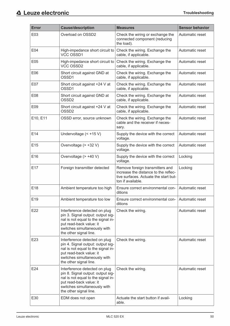
Troubleshooting
Leuze electronic MLC 520 EX 50
Error Cause/description Measures Sensor behavior
E03 Overload on OSSD2 Check the wiring or exchange theconnected component (reducingthe load).
Automatic reset
E04 High-impedance short circuit toVCC OSSD1
Check the wiring. Exchange thecable, if applicable.
Automatic reset
E05 High-impedance short circuit toVCC OSSD2
Check the wiring. Exchange thecable, if applicable.
Automatic reset
E06 Short circuit against GND atOSSD1
Check the wiring. Exchange thecable, if applicable.
Automatic reset
E07 Short circuit against +24 V atOSSD1
Check the wiring. Exchange thecable, if applicable.
Automatic reset
E08 Short circuit against GND atOSSD2
Check the wiring. Exchange thecable, if applicable.
Automatic reset
E09 Short circuit against +24 V atOSSD2
Check the wiring. Exchange thecable, if applicable.
Automatic reset
E10, E11 OSSD error, source unknown Check the wiring. Exchange thecable and the receiver if neces-sary.
Automatic reset
E14 Undervoltage (< +15 V) Supply the device with the correctvoltage.
Automatic reset
E15 Overvoltage (> +32 V) Supply the device with the correctvoltage.
Automatic reset
E16 Overvoltage (> +40 V) Supply the device with the correctvoltage.
Locking
E17 Foreign transmitter detected Remove foreign transmitters andincrease the distance to the reflec-tive surfaces. Actuate the start but-ton if available.
Locking
E18 Ambient temperature too high Ensure correct environmental con-ditions
Automatic reset
E19 Ambient temperature too low Ensure correct environmental con-ditions
Automatic reset
E22 Interference detected on plugpin 3. Signal output: output sig-nal is not equal to the signal in-put read-back value: itswitches simultaneously withthe other signal line.
Check the wiring. Automatic reset
E23 Interference detected on plugpin 4. Signal output: output sig-nal is not equal to the signal in-put read-back value: itswitches simultaneously withthe other signal line.
Check the wiring. Automatic reset
E24 Interference detected on plugpin 8. Signal output: output sig-nal is not equal to the signal in-put read-back value: itswitches simultaneously withthe other signal line.
Check the wiring. Automatic reset
E30 EDM does not open Actuate the start button if avail-able.
Locking
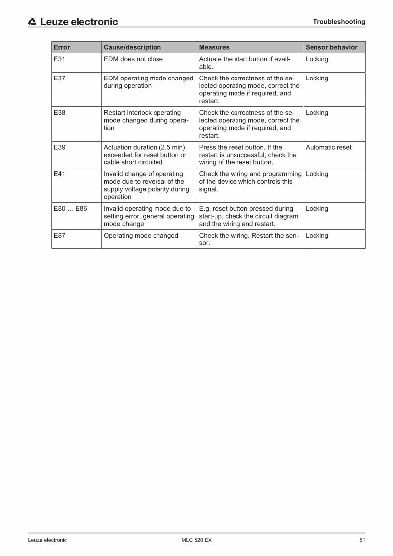
Troubleshooting
Leuze electronic MLC 520 EX 51
Error Cause/description Measures Sensor behavior
E31 EDM does not close Actuate the start button if avail-able.
Locking
E37 EDM operating mode changedduring operation
Check the correctness of the se-lected operating mode, correct theoperating mode if required, andrestart.
Locking
E38 Restart interlock operatingmode changed during opera-tion
Check the correctness of the se-lected operating mode, correct theoperating mode if required, andrestart.
Locking
E39 Actuation duration (2.5 min)exceeded for reset button orcable short circuited
Press the reset button. If therestart is unsuccessful, check thewiring of the reset button.
Automatic reset
E41 Invalid change of operatingmode due to reversal of thesupply voltage polarity duringoperation
Check the wiring and programmingof the device which controls thissignal.
Locking
E80 … E86 Invalid operating mode due tosetting error, general operatingmode change
E.g. reset button pressed duringstart-up, check the circuit diagramand the wiring and restart.
Locking
E87 Operating mode changed Check the wiring. Restart the sen-sor.
Locking
Disposal
Leuze electronic MLC 520 EX 52
12 DisposalÄ For disposal observe the applicable national regulations regarding electronic components.

Service and support
Leuze electronic MLC 520 EX 53
13 Service and support24-hour on-call service at: +49 7021 573-0
Service hotline: +49 7021 573-123
E-mail:[email protected]
Return address for repairs:ServicecenterLeuze electronic GmbH + Co. KGIn der Braike 1D-73277 Owen/Germany
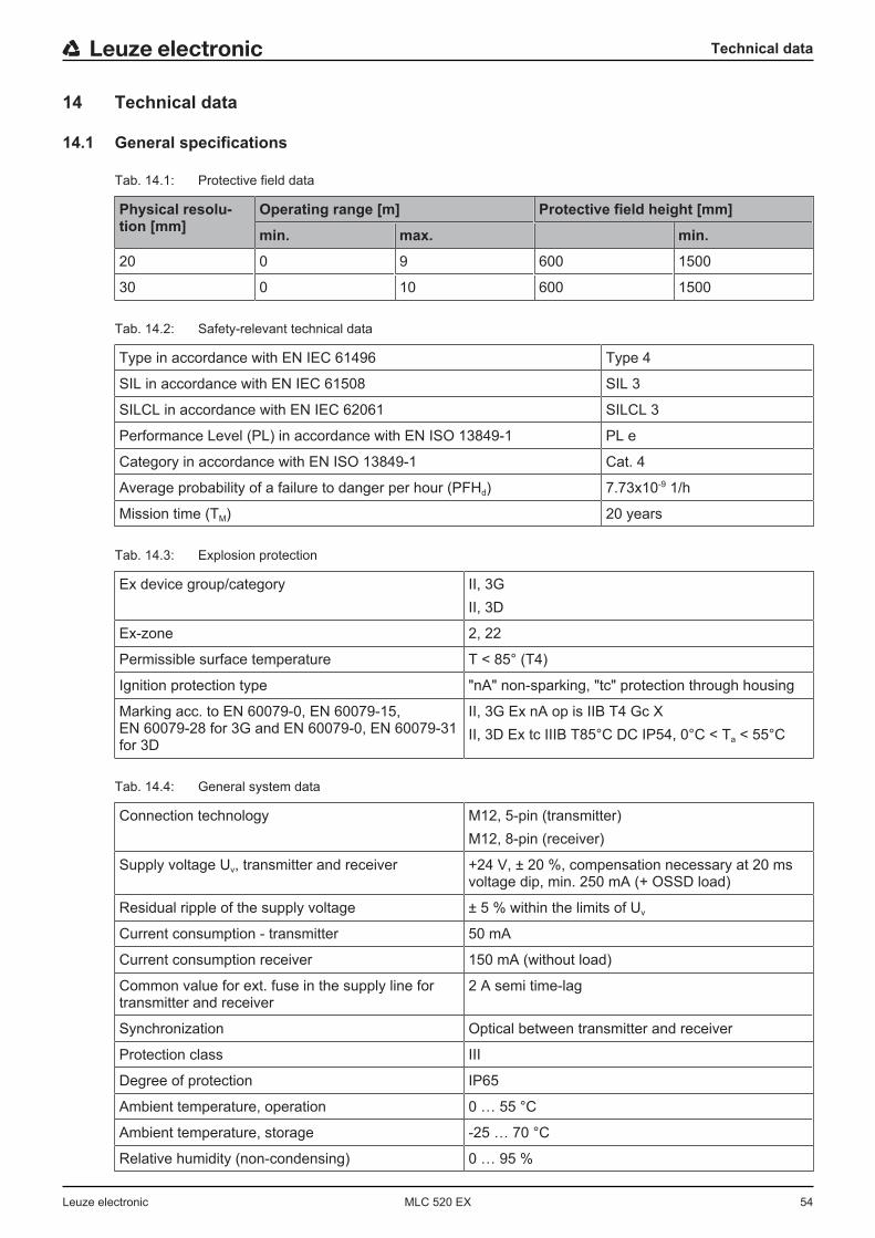
Technical data
Leuze electronic MLC 520 EX 54
14 Technical data
14.1 General specifications
Tab. 14.1: Protective field data
Physical resolu-tion [mm]
Operating range [m] Protective field height [mm]
min. max. min.
20 0 9 600 1500
30 0 10 600 1500
Tab. 14.2: Safety-relevant technical data
Type in accordance with EN IEC 61496 Type 4
SIL in accordance with EN IEC 61508 SIL 3
SILCL in accordance with EN IEC 62061 SILCL 3
Performance Level (PL) in accordance with EN ISO 13849‑1 PL e
Category in accordance with EN ISO 13849‑1 Cat. 4
Average probability of a failure to danger per hour (PFHd) 7.73x10⁻⁹ 1/h
Mission time (TM) 20 years
Tab. 14.3: Explosion protection
Ex device group/category II, 3GII, 3D
Ex-zone 2, 22
Permissible surface temperature T < 85° (T4)
Ignition protection type "nA" non-sparking, "tc" protection through housing
Marking acc. to EN 60079-0, EN 60079-15,EN 60079-28 for 3G and EN 60079-0, EN 60079-31for 3D
II, 3G Ex nA op is IIB T4 Gc XII, 3D Ex tc IIIB T85°C DC IP54, 0°C < Ta < 55°C
Tab. 14.4: General system data
Connection technology M12, 5-pin (transmitter)M12, 8-pin (receiver)
Supply voltage Uv, transmitter and receiver +24 V, ± 20 %, compensation necessary at 20 msvoltage dip, min. 250 mA (+ OSSD load)
Residual ripple of the supply voltage ± 5 % within the limits of Uv
Current consumption - transmitter 50 mA
Current consumption receiver 150 mA (without load)
Common value for ext. fuse in the supply line fortransmitter and receiver
2 A semi time-lag
Synchronization Optical between transmitter and receiver
Protection class III
Degree of protection IP65
Ambient temperature, operation 0 … 55 °C
Ambient temperature, storage -25 … 70 °C
Relative humidity (non-condensing) 0 … 95 %
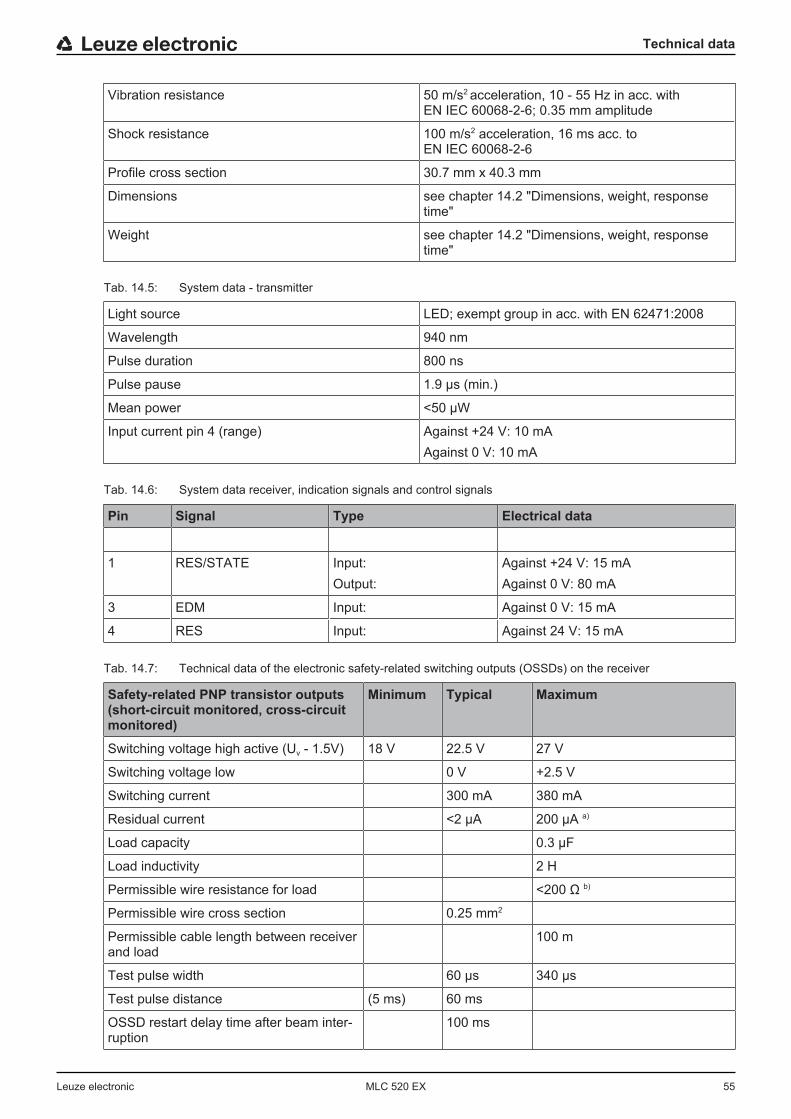
Technical data
Leuze electronic MLC 520 EX 55
Vibration resistance 50 m/s2 acceleration, 10 - 55 Hz in acc. withEN IEC 60068-2-6; 0.35 mm amplitude
Shock resistance 100 m/s2 acceleration, 16 ms acc. toEN IEC 60068-2-6
Profile cross section 30.7 mm x 40.3 mm
Dimensions see chapter 14.2 "Dimensions, weight, responsetime"
Weight see chapter 14.2 "Dimensions, weight, responsetime"
Tab. 14.5: System data - transmitter
Light source LED; exempt group in acc. with EN 62471:2008
Wavelength 940 nm
Pulse duration 800 ns
Pulse pause 1.9 µs (min.)
Mean power <50 µW
Input current pin 4 (range) Against +24 V: 10 mAAgainst 0 V: 10 mA
Tab. 14.6: System data receiver, indication signals and control signals
Pin Signal Type Electrical data
1 RES/STATE Input:Output:
Against +24 V: 15 mAAgainst 0 V: 80 mA
3 EDM Input: Against 0 V: 15 mA
4 RES Input: Against 24 V: 15 mA
Tab. 14.7: Technical data of the electronic safety-related switching outputs (OSSDs) on the receiver
Safety-related PNP transistor outputs(short-circuit monitored, cross-circuitmonitored)
Minimum Typical Maximum
Switching voltage high active (Uv - 1.5V) 18 V 22.5 V 27 V
Switching voltage low 0 V +2.5 V
Switching current 300 mA 380 mA
Residual current <2 µA 200 µA a)
Load capacity 0.3 µF
Load inductivity 2 H
Permissible wire resistance for load <200 Ω b)
Permissible wire cross section 0.25 mm2
Permissible cable length between receiverand load
100 m
Test pulse width 60 μs 340 μs
Test pulse distance (5 ms) 60 ms
OSSD restart delay time after beam inter-ruption
100 ms

Technical data
Leuze electronic MLC 520 EX 56
a) In the event of a failure (if the 0 V cable is interrupted), each of the outputs behaves as a 120 kΩ resistorto Uv. A downstream safety PLC must not detect this as a logical "1".b) Note the additional restrictions due to cable length and load current.
NOTICE
The safety-related transistor outputs perform the spark extinction. With transistor outputs, it istherefore neither necessary nor permitted to use the spark extinction circuits recommended bycontactor or valve manufacturers (RC elements, varistors or recovery diodes), since these con-siderably extend the decay times of inductive switching elements.
Tab. 14.8: Patents
US patents US 6,418,546 B
14.2 Dimensions, weight, response timeDimensions, weight and response time are dependent on
• the resolution• the length
RR
30
,74
0,3
BH
PFN C
A
M12
Fig. 14.1: Dimensions of transmitter and receiver
Effective protective field height HPFE goes beyond the dimensions of the optics area to the outer borders ofthe circles labeled with R.
Calculation of the effective protective field height
HPFE [mm] = Effective protective field heightHPFN [mm] = Rated protective field height, this corresponds to the length of the yellow housing part (see ta-
bles below)A [mm] = Total heightB [mm] = Additional dimensions for calculation of the effective protective field height (see table below)C [mm] = Value for calculating the effective protective field height (see tables below)
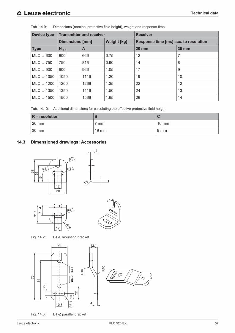
Technical data
Leuze electronic MLC 520 EX 57
Tab. 14.9: Dimensions (nominal protective field height), weight and response time
Device type Transmitter and receiver Receiver
Dimensions [mm] Weight [kg] Response time [ms] acc. to resolution
Type HPFN A 20 mm 30 mm
MLC…-600 600 666 0.75 12 7
MLC…-750 750 816 0.90 14 8
MLC…-900 900 966 1.05 17 9
MLC…-1050 1050 1116 1.20 19 10
MLC…-1200 1200 1266 1.35 22 12
MLC…-1350 1350 1416 1.50 24 13
MLC…-1500 1500 1566 1.65 26 14
Tab. 14.10: Additional dimensions for calculating the effective protective field height
R = resolution B C
20 mm 7 mm 10 mm
30 mm 19 mm 9 mm
14.3 Dimensioned drawings: Accessories
39
16
29
12
R10
R3.1
4
R6
R3.1
R10
30
12
R3.1
18.4
31.7
Fig. 14.2: BT-L mounting bracket
73
61
6.2
6.2
R3.1
R10 R10
22
10
R3.1
10.84
25 12.1
Fig. 14.3: BT-Z parallel bracket
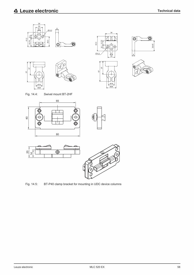
Technical data
Leuze electronic MLC 520 EX 58
20
8,2
34
9,1
23,7
541,2
28,3
Ø 6,2
837
57
18Ø
28Ø
42,3
12,7
59,1
Ø 6,2 8,2
20
34
8
29,4
5
37
57
18Ø
28Ø
Fig. 14.4: Swivel mount BT-2HF
65
80
40
20
14
Fig. 14.5: BT-P40 clamp bracket for mounting in UDC device columns

Technical data
Leuze electronic MLC 520 EX 59
20
8
50
20,5
39
60
Ø 5,3 (2x)Ø 5,3 (2x)
34
Fig. 14.6: Swiveling mounting bracket BT-2SB10

Order guide and accessories
Leuze electronic MLC 520 EX 60
15 Order guide and accessoriesNomenclaturePart designation:MLCxyy-za-hhhhei-ooo
Tab. 15.1: Part number code
MLC Safety sensor
x Series: 3 for MLC 300
x Series: 5 for MLC 500
yy Function classes:00: Transmitter01: Transmitter02: Transmitter with test input10: Basic receiver - automatic restart11: Basic receiver - automatic restart20: Standard receiver - EDM/RES selectable30: Extended receiver - blanking/muting
z Device type:T: transmitterR: receiver
a Resolution:14: 14 mm20: 20 mm30: 30 mm40: 40 mm90: 90 mm
hhhh Protective field height:150 … 3000: from 150 mm to 3000 mm
e Host/Guest (optional):H: HostMG: Middle GuestG: Guest
i Interface (optional):/A: AS-i
ooo Option:EX2: explosion protection (zones 2 + 22)/V: high Vibration-proof
Tab. 15.2: Part descriptions, examples
Examples for part desig-nation
Properties
MLC500T20-900-EX2 Type 4 transmitter, PL e, SIL 3, resolution 20 mm, protective field height900 mm, explosion protection
MLC520R30-600-EX2 Type 4 Standard receiver, PL e, SIL 3, resolution 30 mm, protective fieldheight 600 mm, explosion protection
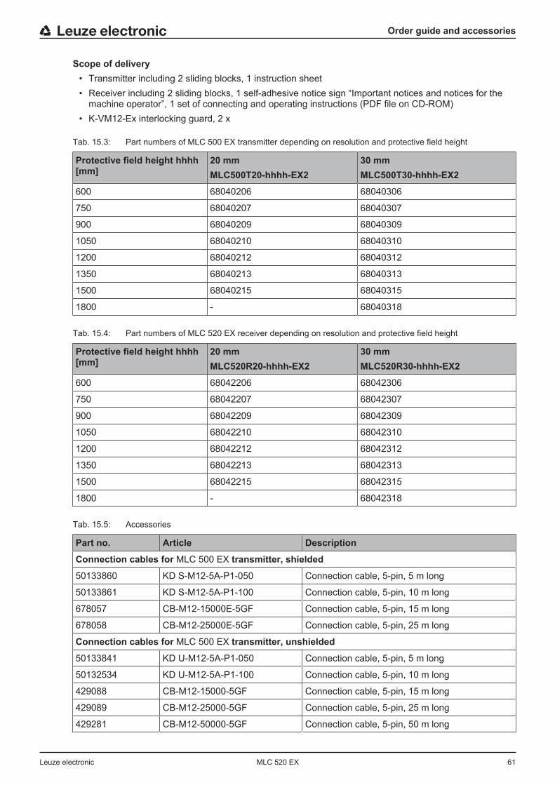
Order guide and accessories
Leuze electronic MLC 520 EX 61
Scope of delivery• Transmitter including 2 sliding blocks, 1 instruction sheet• Receiver including 2 sliding blocks, 1 self-adhesive notice sign “Important notices and notices for the
machine operator”, 1 set of connecting and operating instructions (PDF file on CD-ROM)• K-VM12-Ex interlocking guard, 2 x
Tab. 15.3: Part numbers of MLC 500 EX transmitter depending on resolution and protective field height
Protective field height hhhh[mm]
20 mmMLC500T20-hhhh-EX2
30 mmMLC500T30-hhhh-EX2
600 68040206 68040306
750 68040207 68040307
900 68040209 68040309
1050 68040210 68040310
1200 68040212 68040312
1350 68040213 68040313
1500 68040215 68040315
1800 - 68040318
Tab. 15.4: Part numbers of MLC 520 EX receiver depending on resolution and protective field height
Protective field height hhhh[mm]
20 mmMLC520R20-hhhh-EX2
30 mmMLC520R30-hhhh-EX2
600 68042206 68042306
750 68042207 68042307
900 68042209 68042309
1050 68042210 68042310
1200 68042212 68042312
1350 68042213 68042313
1500 68042215 68042315
1800 - 68042318
Tab. 15.5: Accessories
Part no. Article Description
Connection cables for MLC 500 EX transmitter, shielded
50133860 KD S-M12-5A-P1-050 Connection cable, 5-pin, 5 m long
50133861 KD S-M12-5A-P1-100 Connection cable, 5-pin, 10 m long
678057 CB-M12-15000E-5GF Connection cable, 5-pin, 15 m long
678058 CB-M12-25000E-5GF Connection cable, 5-pin, 25 m long
Connection cables for MLC 500 EX transmitter, unshielded
50133841 KD U-M12-5A-P1-050 Connection cable, 5-pin, 5 m long
50132534 KD U-M12-5A-P1-100 Connection cable, 5-pin, 10 m long
429088 CB-M12-15000-5GF Connection cable, 5-pin, 15 m long
429089 CB-M12-25000-5GF Connection cable, 5-pin, 25 m long
429281 CB-M12-50000-5GF Connection cable, 5-pin, 50 m long
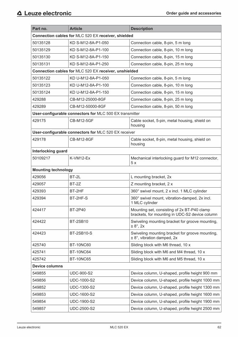
Order guide and accessories
Leuze electronic MLC 520 EX 62
Part no. Article Description
Connection cables for MLC 520 EX receiver, shielded
50135128 KD S-M12-8A-P1-050 Connection cable, 8-pin, 5 m long
50135129 KD S-M12-8A-P1-100 Connection cable, 8-pin, 10 m long
50135130 KD S-M12-8A-P1-150 Connection cable, 8-pin, 15 m long
50135131 KD S-M12-8A-P1-250 Connection cable, 8-pin, 25 m long
Connection cables for MLC 520 EX receiver, unshielded
50135122 KD U-M12-8A-P1-050 Connection cable, 8-pin, 5 m long
50135123 KD U-M12-8A-P1-100 Connection cable, 8-pin, 10 m long
50135124 KD U-M12-8A-P1-150 Connection cable, 8-pin, 15 m long
429288 CB-M12-25000-8GF Connection cable, 8-pin, 25 m long
429289 CB-M12-50000-8GF Connection cable, 8-pin, 50 m long
User-configurable connectors for MLC 500 EX transmitter
429175 CB-M12-5GF Cable socket, 5-pin, metal housing, shield onhousing
User-configurable connectors for MLC 520 EX receiver
429178 CB-M12-8GF Cable socket, 8-pin, metal housing, shield onhousing
Interlocking guard
50109217 K-VM12-Ex Mechanical interlocking guard for M12 connector,5 x
Mounting technology
429056 BT-2L L mounting bracket, 2x
429057 BT-2Z Z mounting bracket, 2 x
429393 BT-2HF 360° swivel mount, 2 x incl. 1 MLC cylinder
429394 BT-2HF-S 360° swivel mount, vibration-damped, 2x incl.1 MLC cylinder
424417 BT-2P40 Mounting set, consisting of 2x BT-P40 clampbrackets, for mounting in UDC-S2 device column
424422 BT-2SB10 Swiveling mounting bracket for groove mounting,± 8°, 2x
424423 BT-2SB10-S Swiveling mounting bracket for groove mounting,± 8°, vibration damped, 2x
425740 BT-10NC60 Sliding block with M6 thread, 10 x
425741 BT-10NC64 Sliding block with M6 and M4 thread, 10 x
425742 BT-10NC65 Sliding block with M6 and M5 thread, 10 x
Device columns
549855 UDC-900-S2 Device column, U-shaped, profile height 900 mm
549856 UDC-1000-S2 Device column, U-shaped, profile height 1000 mm
549852 UDC-1300-S2 Device column, U-shaped, profile height 1300 mm
549853 UDC-1600-S2 Device column, U-shaped, profile height 1600 mm
549854 UDC-1900-S2 Device column, U-shaped, profile height 1900 mm
549857 UDC-2500-S2 Device column, U-shaped, profile height 2500 mm

Order guide and accessories
Leuze electronic MLC 520 EX 63
Part no. Article Description
Deflecting mirror columns
549780 UMC-1000-S2 Continuous deflecting mirror column 1000 mm
549781 UMC-1300-S2 Continuous deflecting mirror column 1300 mm
549782 UMC-1600-S2 Continuous deflecting mirror column 1600 mm
549783 UMC-1900-S2 Continuous deflecting mirror column 1900 mm
Deflecting mirror
529606 UM60-600 Deflecting mirror, mirror length 660 mm
529607 UM60-750 Deflecting mirror, mirror length 810 mm
529609 UM60-900 Deflecting mirror, mirror length 960 mm
529610 UM60-1050 Deflecting mirror, mirror length 1110 mm
529612 UM60-1200 Deflecting mirror, mirror length 1260 mm
529613 UM60-1350 Deflecting mirror, mirror length 1410 mm
529615 UM60-1500 Deflecting mirror, mirror length 1560 mm
430105 BT-2UM60 Mounting bracket for UM60, 2x
Laser alignment aids
560020 LA-78U External laser alignment aid
520004 LA-78UDC External laser alignment aid for fastening in De-vice Column
520101 AC-ALM-M Alignment aid
Test rods
349945 AC-TR14/30 Test rod 14/30 mm
349939 AC-TR20/40 Test rod 20/40 mm
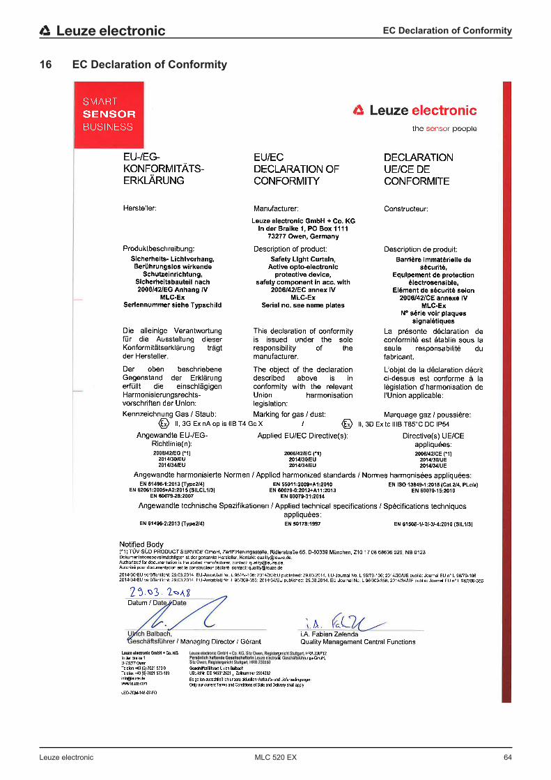
EC Declaration of Conformity
Leuze electronic MLC 520 EX 64
16 EC Declaration of Conformity