ML250 EN DS015REV02 IS - cms.esi.info · 256 records collected at the Measure Sample Rate ... 7.24...
14
F F L L O O W W I I Z Z ™ ™ (ML 250) THE MOST ACCURATE BATTERY POWERED SYSTEM Warranty conditions are available on this website: www.isomag.eu only in English version Electroma g g netic Con v v erter with batter y y and universal power supply. Optional in built modules for pressure measure and G G P P R R S S t t r r a a n n s s m m i i s s s s i i o o n n . .
Transcript of ML250 EN DS015REV02 IS - cms.esi.info · 256 records collected at the Measure Sample Rate ... 7.24...

FFLLOOWWIIZZ™™
(( MM LL 22 55 00 ))
TH
E M
OS
T A
CC
UR
AT
E B
AT
TE
RY
PO
WE
RE
D S
YS
TE
M
Warranty conditions are available on this website: www.isomag.eu only in English version
EE ll ee cc tt rr oo mm aa gg nn ee tt ii cc CC oo nn vv ee rr tt ee rr ww ii tt hh bb aa tt tt ee rr yy aa nn dd uu nn ii vv ee rr ss aa ll pp oo ww ee rr ss uu pp pp ll yy .. OO pp tt ii oo nn aa ll ii nn bb uu ii ll tt mm oo dd uu ll ee ss ff oo rr pp rr ee ss ss uu rr ee mm ee aa ss uu rr ee aa nn dd GG PP RR SS tt rr aa nn ss mm ii ss ss ii oo nn ..

ML 250
The manufacturer guarantees only English text Page 2 of 14 ML250_EN_DS015REV02_IS.doc available on our web site: www.isomag.eu
TT EE CC HH NN II CC AA LL DD AA TT AA
Suitable for All the ISOMAG sensors
Minimum Conductivity 5 μS/cm
Version/Housing materials Wall/Compact: Painted Aluminium die casting (OPT. AISI304)
Dimensions See Drawing
Protection rating IP 67 IP 68 ( OPTIONAL )
Connection sensor cable C015 / C016 cable (maximum length 20 meters )
Cable gland standard PG 11/Connectors (Opt.)
Ambient temperature -20…+60°C
LCD Display Alphanumerical display: 2 lines x 16 characters NO back light
Keyboard 3 membrane keys
Pressure measure Input for Pressure sensor (0÷2000 , 0÷4000 Kpa)
Additional Modules n°2/4 On/Off out + n°1 On/Off input, RS232 Serial Communication, GSM /GPRS (SMS/CSD system)
Data Logger
Two Sets ( 1 Mbit ). 8192 records collected at intervals of 1,2,3,5,15,30,60 minutes 256 records collected at the Measure Sample Rate Note: both sets of records contain Date/Time reference, Flow Rate,
Positive and Negative volumes and auxiliary Input data (Pressure) expressed in Technical Units
Recording of the last 64 alarm Events
Bi-directional Yes
Full Scale value 0,4…10 m/s
Diagnostic functions Yes
Empty Pipe Detection Yes
Galvanic Isolation All Inputs/Outputs are galvanically insulated from Power Supply
Data storage EEprom, battery backup RAM
Programming plug in Protected plug in for connection to PC ( IF2x)
CE certification Yes
Accuracy See table below
Power Supply (see details pag.5)
Standard: n°1 size D not rechargeable Lithium Battery, Life Time 2 Years using 15s Sampling Rate, 1 month with Continuous Sampling Rate; Universal Power Supply 10÷400 Vac/dc; functioning also as mixed system network Power Supply + Battery as backup. Optional: up to n° 6 Lithium batteries ( up to 10 years )
Power consumption 0.08W with battery, 0.2W with Universal Power Supply

ML 250
The manufacturer guarantees only English text Page 3 of 14 ML250_EN_DS015REV02_IS.doc available on our web site: www.isomag.eu
OO VV EE RR AA LL LL DD II MM EE NN SS II OO NN SS
170
146
146
171
162
230
40
25
125
152*
CC OO MM PP AA CC TT VV EE RR SS II OO NN
SS EE PP AA RR AA TT EE VV EE RR SS II OO NN

ML 250
The manufacturer guarantees only English text Page 4 of 14 ML250_EN_DS015REV02_IS.doc available on our web site: www.isomag.eu
Alarm ON visualization
Flow rate value
Direct flow rate and positive totalizer
Pressure
Totalized values
Scrolling visualization of data
Flow rate and flow velocity
Battery status / Antenna signal strength
VV II SS UU AA LL II ZZ AA TT II OO NN PP AA GG EE SS
Different visualisation possibilities with the simple press of a key

ML 250
The manufacturer guarantees only English text Page 5 of 14 ML250_EN_DS015REV02_IS.doc available on our web site: www.isomag.eu
PP OO WW EE RR SS UU PP PP LL YY
MAIN POWER
BATTERIES
With mains power supply the batteries are automatically excluded and the converter always works at the maximum sampling rate (continuous sampling).
To avoid drawing the batteries in a very short period of time activate the ‘Energy Saving’ function and set the ‘Measure Interval’ to a set value.

ML 250
The manufacturer guarantees only English text Page 6 of 14 ML250_EN_DS015REV02_IS.doc available on our web site: www.isomag.eu
PP OO WW EE RR SS UU PP PP LL YY LL AA YY OO UU TT
Power supply by main voltage 10-400 V AC/DC (OPTIONAL)
Battery connectors
Batteries dip switch

ML 250
The manufacturer guarantees only English text Page 7 of 14 ML250_EN_DS015REV02_IS.doc available on our web site: www.isomag.eu
EE LL EE CC TT RR II CC AA LL CC OO NN NN EE CC TT II OO NN SS
TERMINAL BLOCK: COMPACT/SEPARATE VERSION
1 2 3 4 5 6 7 8 9 10
11 12 13 14 15 16 17 18 19 20
E1 E2 C SC + - GND/TX/RXELECTRODES INPUT RS232
ECECSC
B2B1SCOUT2OUT1COILS
STANDARD ON/OFF OUTPUT
Terminal 16 / 18
Terminal 17 / 19
(Out1) (Out2)
(Out1) (Out2)
43 V
ON/OFF OUTPUT

ML 250
The manufacturer guarantees only English text Page 8 of 14 ML250_EN_DS015REV02_IS.doc available on our web site: www.isomag.eu
IP 68 EXECUTION : CONNECTION WITH IP 68 CONNECTORS
PRESSURE PROBE CABLE
SENSOR'S CABLES
OUTPUTS CABLE
PULSES
ALARM

ML 250
The manufacturer guarantees only English text Page 9 of 14 ML250_EN_DS015REV02_IS.doc available on our web site: www.isomag.eu
1.1 Insert ND of sensor (0-3000)1.2 Calibration data of sensor visualized on sensor's label1.3 Sensors model: Enter the first two characters of the serial number of the sensor1.4 Position for insertion sensors: 0=1/8DN, 1=1/2DN, 2=7/8DN
1.5 Factory parameter
1.6 Automatic setting according to ID ( insertion meter only )1.7 Automatic setting according to ID ( insertion meter only )1.8 Enables the empty pipe detection function1.9 Value of empty pipe sensibility detection1.10*Enables the automatic zero calibration system1.11 Reset the preceding value
2.1* Full scale value measure set2.2* Unit of measure and number of decimal totalizes2.3* Pulse value on channel 12.4* Pulse value on channel 22.5* Duration of the pulse generated on channel 12.6* Duration of the pulse generated on channel 22.7 Full scale value set for pressure measure
3.1* Time constant3.2 Low flow zero threshold: 0-25% of full scale value3.3 Enable every hour an internal cycle of calibration. The measure it's stopped for 8-15 sec.3.4* Energy saving function enabling3.5 Number of samples in energy saving ON3.6 Interval time of the measure when energy saving function is enabled (page 12)3.7 Factory parameter
4.1 Maximum value alarm set for direct flow rate4.2 Maximum value alarm set for reverse flow rate4.3 Minimum value alarm set for direct flow rate4.4 Minimum value alarm set for reverse flow rate4.5 Maximum value alarm set for pressure4.6 Minimum value alarm set for pressure4.7 Hysteresis threshold set for the minimum and maximum flow rate alarms
Note: Only relevant or accessible functions are shown in the group lists on above. Others will be visible on the converter when powered upbut are not modifiable or influence normal working of the converter.
5.1* Total direct (positive) flow totalise reset enable5.2* Partial direct (positive) flow totalise reset enable5.3* Total reverse (negative) flow totalise reset enable5.4* Partial reverse (negative) flow totalise reset enable5.6 Totalise counting lock command (see page 18)5.7* Autozero calibration external command5.8* Auto- switch on command
6.1* Total direct (positive) flow totalise reset enable6.2* Partial direct (positive) flow totalise reset enable6.3* Total reverse (negative) flow totalise reset enable6.4* Partial reverse (negative) flow totalise reset enable
FUNCTIONS

ML 250
The manufacturer guarantees only English text Page 10 of 14 ML250_EN_DS015REV02_IS.doc available on our web site: www.isomag.eu
7.1 Choice of the communication protocol for the IF2 device7.2 Factory purpose function7.3 Choice of the communication protocol for the RS232 port7.4 Enable SCADA protocol*7.5 Address value of converter (range 0 - 255)7.6 Speed of the RS232 output (possible choices: 2400, 9600, 19200, 38400 bps)7.7 Enables the sending of emails*7.8 Interval of e-mail sending*7.9 Time of sending data*7.10 Delay of data sending (USEFUL FOR SCADA SYSTEM)*7.11 Minimum radio signal to allow the communications7.12 Enables the sending of STATIC DATA LOGGER by e-mail*7.13 Enables the sending of DINAMIC DATA LOGGER by e-mail*7.14 Enables the sending of EVENTS by e-mail*7.15 Enable the SMS operations*7.16 Interval of SMS checking*7.17 Enable the SMS over event*7.18 SMS Process Data Send Enable*7.19 Enables the sending of STATIC DATA LOGGER by SMS*7.20 Enables clock synchronization with a specified server via the HTTP protocol*7.21 Roaming enable*7.22 Send data through e-mail immediately (according to settings of above functions) 7.23 Send config through e-mail immediately*7.24 Send process data through sms immediately(according of above functions)* 7.25 Send data logger through sms immediately(according of above functions) *
* (Communication function group only) = see wireless specific manual supplied for more details
8.1 Choice of the language: EN= English, IT=Italian, FR= French, SP= Spanish8.2* Total direct (positive) flow totalizer reset from keyboard8.3* Partial direct (positive) flow totalizer reset from keyboard8.4* Total reverse (negative) flow totalizer reset enable from keyboard8.5* Partial reverse (negative) flow totalizer reset enable from keyboard8.6 Time for switch off display (shown with function 3.7 enabled)8.7 Visualization of "Quick start menu"8.8 Enable the page of net totalizer (difference between direct and reverse. see page 16)8.9 Visualizes the values of the partial totalizer in the unit of selected currency8.10 Choice of the numbers of decimals for the visualization currency value: From 0 to 38.11* Value of conversion/currency for direct totalizer8.12* Value of conversion/currency for reverse totalizer
9.1* Automatic data logger enable9.2* Date and time set9.3 Set of Time Zone ( Against GMT -12 to +12 hours)9.4* Interval time for the data logging function: 1, 2, 3, 5, 15, 30, 60 minutes9.5 Enables the sending of direct totalizer9.6 Enables the sending of reverse totalizer9.7 Enables the flow rate sending 9.8 Enables the sending of an auxiliary input ( PRESSURE ) 9.9 Enables the sending of measure units ( technical units ) 9.10 Choice of the separator character for CSV format ("," or ";")9.11*Display dynamic data9.12 Displaying of the data stored in the data logger9.13 Displaying of the last 64 alarms stored in the data logger9.14 Visualization function of minimum and maximum peak of flow rate9.15 Logged dynamic data clearing function9.16 Logged data clearing function9.17 Reset all alarm events9.18 Reset all minimum and maximum peak of flow rate stored

ML 250
The manufacturer guarantees only English text Page 11 of 14 ML250_EN_DS015REV02_IS.doc available on our web site: www.isomag.eu
10.1* Enable the calibration of the converter10.2* Converter auto-test10.3* Flow rate simulation enabling10.4* Stand-by function
11.1 Level 2 access code enter11.2 Block level function can be set from 0 to 311.3 Number of batteries installed11.4 Load factory data pre-set11.5 Load user data saved11.6 Save user data11.7 Visualisation of the total operation hours of the converter (function not editable)11.8 Ks Coefficient
Note : all page number references are to the operating manual .

ML 250
The manufacturer guarantees only English text Page 12 of 14 ML250_EN_DS015REV02_IS.doc available on our web site: www.isomag.eu
tINTERVAL
tSAMPLING FREQUENCY
MM EE AA SS UU RR EE // SS AA MM PP LL II NN GG FF RR EE QQ UU EE NN CC YY
The ML 250 converter can measure in two different modes:
In this mode the converter measures according to the classic mag meter scheme; the system consumption, for any sensor diameter, is 0,1 W; the battery life is 1 month with 1 battery ; 1 month * N (N = number of additional battery). The system accuracy is defined according to this operation mode.
The mode to sample at intervals allows for large battery power savings; the consumption is the following:
Sampling time (s) Battery life - n° 1 battery (years)
Battery life – “ N “ batteries (years)
1 0,7 0,7 * N 2 1.3 1.3 * N 5 2.1 2.1 * N 10 2.7 2.7 * N 15 3.0 3.0 * N
Regardless of the number of batteries, the maximum operating time is limited to 10 years
CONTINUOUS SAMPLING
SAMPLING AT PROGRAMMED INTERVAL
ML 250
The manufacturer guarantees only English text Page 13 of 14 ML250_EN_DS015REV02_IS.doc available on our web site: www.isomag.eu
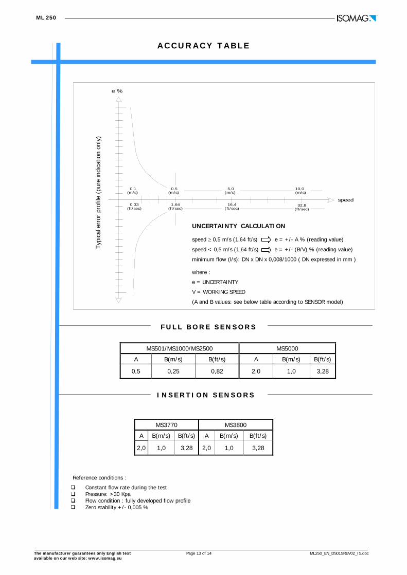
A C C U R A C Y T A B L E
Reference conditions :
MS501/MS1000/MS2500 MS5000
A B(m/s) B(ft/s) A B(m/s) B(ft/s)
0,5 0,25 0,82 2,0 1,0 3,28
MS3770 MS3800
A B(m/s) B(ft/s) A B(m/s) B(ft/s)
2,0 1,0 3,28 2,0 1,0 3,28
FF UU LL LL BB OO RR EE SS EE NN SS OO RR SS
Constant flow rate during the test Pressure: >30 Kpa Flow condition : fully developed flow profile Zero stability +/- 0,005 %
Typi
cal e
rror
pro
file
(pur
e in
dica
tion
only
) e %
speed
0,1 (m/s)
0,33(ft/sec)
0,5 (m/s)
1,64(ft/sec)
5,0 (m/s)
16,4(ft/sec)
10,0 (m/s)
32,8(ft/sec)
UNCERTAINTY CALCULATION speed ≥ 0,5 m/s (1,64 ft/s) e = +/- A % (reading value)
speed < 0,5 m/s (1,64 ft/s) e = +/- (B/V) % (reading value)
minimum flow (l/s): DN x DN x 0,008/1000 ( DN expressed in mm )
where :
e = UNCERTAINTY
V = WORKING SPEED
(A and B values: see below table according to SENSOR model)
II NN SS EE RR TT II OO NN SS EE NN SS OO RR SS

ML 250
Production/stock 35044 Montagnana – PD Via Piemonte , n° 2
H O W T O O R D E R
The manufacturer reserves the right to make design improvements without notice.
DisplayML 250
B
0
ML 250 B 0 1 B EXAMPLE OF CODE FOR ORDER
Alphanumeric LCD display 2 line, each of 16 characters and 3 programming keys
D
A
Power supply
A
0
1
4
Housing material - Protection rate
Painted aluminum die casting , protection rate IP 67 - MODULE AVAILABLE : 0-3-4-5-7-8-a-b
Version
Separate version for wall monting, complete with mounting accessoriesin Stainless Steel (AISI 304) ; CABLE C015/C016
Compact version with sensor MS.... (liquid maximum temperature 100 °C)
N° 1 Lithium Battery - Without Universal
A
Input
WALL VERSIONCOMPACT VERSION
123411121356789101415
A
N° 1 LITHIUM BATTERY+ UNIVERSAL POWER SUPPLY
1
Additional module
Without additional module
3 n. 2 ON/OFF out
4
GPRS MODULE (Ant. on converter)+ETP+Flowiz Serv.7
RS 232 communication port
5
Z
1
Without remote input
Other
b
ML 250
C
BOARD
Blind version without display and keyboard
Pressure input with IP 68 male connector( to be specified the pressure span - add the gauge price ) D
AISI304 housing, protection rate IP67 ( DISPLAY NOT ROTABLE ) MODULE AVAILABLE : 0-3-4-5-7-8-a-b1
Separate version for wall monting, complete with mounting accessoriesin Carbon Steel (painted RAL6028) ; CABLE C015/C016
B
5 AISI304 housing, IP68 1,5 meters under water ( ONLY COMPACT DISPLAY NOT ROTABLE ) - MODULE AVAILABLE : 7-9
2 N° 4 LITHIUM BATTERY(1+1 OF 3 ELEMENTS PACK NECESSARY WITH GPRS ) + UNIVERSAL
Painted aluminum die casting IP 68 1,5 meters under water(ONLY COMPACT DISPLAY NOT ROTABLE) - MODULE AVAILABLE : 7-9-c-d6
8
N° 6 LITHIUM BATTERY ( N° 2 X 3 ELEMENTS PACK ) - WITHOUT UNIVERSAL
WITHOUT BATTERY WITHOUT UNIVERSAL POWER SUPPLY
GPRS MODULE (Ant. 3 meters cable)+ETP+Flowiz Serv.
a
Input for pressure probe ( to be specified the pressure span - add the gauge price )
7 WITHOUT BATTERY WITH UNIVERSAL POWER SUPPLY
7 Painted aluminum die casting IP 68 1,5 meters under water ( ONLY FOR SEPARATE VERSION ,DISPLAY NOT ROTABLE ) MODULE AVAILABLE : 7-9-c-d , COMPLETE WITH 2 CONNECTORS IP 68 FOR CABLE C012/C013
N° 2 DIGITAL OUT + RS 232 WITH IP 68 connector9
8 N° 2 DIGITAL OUT + RS 232
GPRS MODULE (Ant. on converter)+ETP+Flowiz Serv.+ 2 ON/OFF OUTGPRS MODULE (Ant. 3 meters cable)+ETP+Flowiz Serv.+ 2 ON/OFF OUT
N° 3 LITHIUM BATTERY ( N° 1 OF 3 ELEMENTS PACK ) - WITHOUT UNIVERSAL
n° 4 LITHIUM BATTERY( 1+1 OF 3 ELEMENTS PACK NECESSARY WITH GPRS) -WITHOUT UNIVERSAL65
n° 4 ON/OFF out ( max 50 Hz - max 100 mA ) 0
d
c n° 2 ON/OFF out ( max 50 Hz - max 100 mA ) complete with IP 68 connectorn° 4 ON/OFF out ( max 50 Hz - max 100 mA ) complete with IP 68 connector
Special Features
A
A
B
C
NONE
WITH ANTICONDENSE CAP
Female Connector IP68 for the modules : 9,c,d (One piece , 10 contacts)


![Portfolio - Josh Bielick [7.24]](https://static.fdocuments.us/doc/165x107/548692c7b47959dd0c8b528c/portfolio-josh-bielick-724.jpg)


![HOME [cms.esi.info]cms.esi.info/Media/documents/Domai_home2005_ML.pdf · movie tv oscar wide yuppie yuppie bis yuppie cassetto andy cleo 6000 dipsy new secret vetrina rocky 2 top](https://static.fdocuments.us/doc/165x107/606410e5da563e67a546e316/home-cmsesiinfocmsesiinfomediadocumentsdomaihome2005mlpdf-movie-tv.jpg)